Performance improvement of three-phase self-excited...
13
Turk J Elec Eng & Comp Sci (2015) 23: 1660 – 1672 c ⃝ T ¨ UB ˙ ITAK doi:10.3906/elk-1404-191 Turkish Journal of Electrical Engineering & Computer Sciences http://journals.tubitak.gov.tr/elektrik/ Research Article Performance improvement of three-phase self-excited induction generator feeding induction motor load Jyotirmayee DALEI * , Kanungo Barada MOHANTY Department of Electrical Engineering, National Institute of Technology, Rourkela, India Received: 11.04.2014 • Accepted/Published Online: 11.02.2015 • Printed: 30.11.2015 Abstract: In this paper, the transient and steady-state performances of an isolated self-excited induction generator driven by a wind turbine and feeding power to a dynamic load such as a three-phase induction motor are analyzed. Mathematical modeling and simulation study of the whole system, including the wind turbine, induction generator, capacitor, pulse width modulated voltage source inverter, and dynamic load, are carried out with closed-loop voltage and frequency controller. The complete system is modeled in the stationary d-q frame and validated by comparing simulation and experimental results at no-load. The same mathematical model is then used to study the transient performance of the self-excited induction generator supplying to a dynamic load. When the induction motor is connected to the induction generator without any voltage and frequency controller, it causes severe transients in electrical and mechanical variables of the generator. Due to the large starting-current requirement of the induction motor, there is a collapse of the terminal voltage of the generator. A bidirectional pulse width modulated source inverter with DC link battery is connected with the generator and operated in closed-loop control mode to maintain voltage and frequency and to operate the induction motor successfully with variable wind speed and mechanical load. Key words: Wind turbine, self-excited induction generator, dynamic modeling, pulse width modulated voltage source inverter, PI controller 1. Introduction Renewable energy sources, such as wind, photovoltaic, and hydropower plants are recently being paid much attention universally due to excess exploitation of fossil fuels and associated environment pollution. The self- excited induction generator (SEIG) is suitable to generate electrical power from these nonconventional energy sources [1, 2, 3]. To operate as a self-excited induction generator, an induction machine has to be provided with magne- tizing energy. This can be achieved by connecting the capacitor bank [4] across the stator terminals. The major problems with the SEIG are as follows: its terminal voltage and frequency are influenced by the prime mover speed, excitation capacitance, load current, and power factor of the load. With a fixed capacitor bank connected across the stator terminals, it is not possible to keep the terminal voltage of the SEIG constant under varying loads because of the variable reactive power demand, which is not met by the fixed capacitor bank. Therefore, the major problems associated with SEIG are its poor voltage and frequency regulation. However, due to fast response, improved switching features, and the low cost of the power converters, researchers are attracted to explore their applications for performance improvement of SEIGs * Correspondence: jyoti [email protected] 1660
Transcript of Performance improvement of three-phase self-excited...
Turk J Elec Eng & Comp Sci
(2015) 23: 1660 – 1672
c⃝ TUBITAK
doi:10.3906/elk-1404-191
Turkish Journal of Electrical Engineering & Computer Sciences
http :// journa l s . tub i tak .gov . t r/e lektr ik/
Research Article
Performance improvement of three-phase self-excited induction generator feeding
induction motor load
Jyotirmayee DALEI∗, Kanungo Barada MOHANTYDepartment of Electrical Engineering, National Institute of Technology, Rourkela, India
Received: 11.04.2014 • Accepted/Published Online: 11.02.2015 • Printed: 30.11.2015
Abstract: In this paper, the transient and steady-state performances of an isolated self-excited induction generator
driven by a wind turbine and feeding power to a dynamic load such as a three-phase induction motor are analyzed.
Mathematical modeling and simulation study of the whole system, including the wind turbine, induction generator,
capacitor, pulse width modulated voltage source inverter, and dynamic load, are carried out with closed-loop voltage and
frequency controller. The complete system is modeled in the stationary d−q frame and validated by comparing simulation
and experimental results at no-load. The same mathematical model is then used to study the transient performance
of the self-excited induction generator supplying to a dynamic load. When the induction motor is connected to the
induction generator without any voltage and frequency controller, it causes severe transients in electrical and mechanical
variables of the generator. Due to the large starting-current requirement of the induction motor, there is a collapse of
the terminal voltage of the generator. A bidirectional pulse width modulated source inverter with DC link battery is
connected with the generator and operated in closed-loop control mode to maintain voltage and frequency and to operate
the induction motor successfully with variable wind speed and mechanical load.
Key words: Wind turbine, self-excited induction generator, dynamic modeling, pulse width modulated voltage source
inverter, PI controller
1. Introduction
Renewable energy sources, such as wind, photovoltaic, and hydropower plants are recently being paid much
attention universally due to excess exploitation of fossil fuels and associated environment pollution. The self-
excited induction generator (SEIG) is suitable to generate electrical power from these nonconventional energy
sources [1, 2, 3].
To operate as a self-excited induction generator, an induction machine has to be provided with magne-
tizing energy. This can be achieved by connecting the capacitor bank [4] across the stator terminals. The major
problems with the SEIG are as follows: its terminal voltage and frequency are influenced by the prime mover
speed, excitation capacitance, load current, and power factor of the load.
With a fixed capacitor bank connected across the stator terminals, it is not possible to keep the terminal
voltage of the SEIG constant under varying loads because of the variable reactive power demand, which is not
met by the fixed capacitor bank. Therefore, the major problems associated with SEIG are its poor voltage
and frequency regulation. However, due to fast response, improved switching features, and the low cost of the
power converters, researchers are attracted to explore their applications for performance improvement of SEIGs
∗Correspondence: jyoti [email protected]
1660

DALEI and MOHANTY/Turk J Elec Eng & Comp Sci
[5–10]. Wind energy is plentifully available in remote areas, where power grids are not available. Local small-
scale standalone systems can utilize these resources where a grid connection is not feasible. In remote areas,
the majority of electrical loads are induction motors used for domestic and agricultural purposes to pump water
and in flour mills. Therefore, it is vital to study the behavior of the SEIG when it feeds induction motors in
standalone applications. Very few research papers have been reported regarding the operation of SEIGs feeding
induction motor loads.
Short-shunt and long-shunt schemes were reported in [11], but the schemes involve an iterative method
to select the series capacitance. When this type of compensated scheme is used for feeding induction motor
load, oscillations and high transients are observed. The dynamic performance of SEIGs feeding induction motor
loads was reported in [12], where the damping resistor was connected across series capacitors to damp out the
starting transients created by the induction motor when connected to the SEIG and also for getting stable
operation. However, this involves complex mathematical calculations for finding the exact value of the damping
resistor to be connected across the series capacitor. If the value of damping resistance is low, the system
becomes underdamped and voltage collapse occurs. Higher damping resistance makes the system overdamped
and oscillations are sustained. Due to damping resistance, additional losses occur. Transient performance
of a series-compensated SEIG feeding an induction motor was reported in [13]. For successful operation of
the induction motor, proper selection of series and shunt capacitors is required. Otherwise, subsynchronous
resonance results. In [14], performance of a SEIG with static synchronous series compensator (SSSC) and static
compensator (STATCOM) feeding a dynamic load was reported. The SEIG-SSSC system consists of a unity
ratio voltage insertion transformer along with an L-C filter, used to remove high-frequency components from
the output voltage of VSC, and two P-I controllers. For generating reference supply current both in-phase
current templates and the quadrature current templates are involved in both cases. In [15], a simple scheme
was reported with a pulse width modulated (PWM) voltage source inverter (VSI) by taking the R and R− L
load only.
Taking these factors into account, this paper focuses on a simple and reliable voltage and frequency
controller giving very less transient oscillation and very low THD values for a SEIG-fed induction motor load.
In this paper, simulation and experiments on a SEIG with PWM-based VSI feeding induction motor load have
been carried out. With the designed control scheme, the VSI is taking care of the induction motor load and
source perturbations by injecting the required amount of reactive or active power for maintaining the rated
voltage and frequency of the SEIG.
2. System description
The schematic diagram of the whole system is represented in Figure 1. The system consists of a wind turbine,
induction machine as SEIG, capacitor bank as excitation system, induction motor as dynamic load, and a
PWM VSI. The wind turbine drives the SEIG at a desired speed and appropriate values of capacitor bank are
connected across the stator terminals of the SEIG to initiate the self-excitation process and to generate the
rated voltage at no-load. Even after the rated voltage is developed, if an induction motor is connected across
the SEIG terminals without any controller, terminal voltage across the SEIG collapses. To start and run the
induction motor safely, the SEIG is connected with a PWM bidirectional VSI through a coupling transformer
and operated in closed-loop control mode.
3. System modeling
The whole system under study has the following components: wind turbine, induction generator, shunt excita-
tion capacitor bank, induction motor load, and PWM VSI.
1661

DALEI and MOHANTY/Turk J Elec Eng & Comp Sci
+− PI
Controller
mref
IGBT
tω*sin
SEIG Transformer
Coupling
DC
Inverter
SPWM
V
mVofCalculation
mV
Multiply
Load
m
Pulses to
Capacitor Bank
sensor
Voltage
Wind turbine
Figure 1. Schematic diagram of SEIG driven by wind turbine with PWM VSI.
3.1. Modeling of wind turbine
The mechanical power Pt captured by a wind turbine [6] of blade radius r running in a wind stream of velocity
vw is given as
Pt = 0.5ρπr2Cpv3w. (1)
The tip speed ratio (λ) of the wind turbine can be expressed as
λ =wT r
vw. (2)
The polynomial relation between power coefficient CP and tip speed ratio λ at a particular pitch angle
β for the selected wind turbine [6] is
CP (λ, β) = C1
(C2
λi− C3β − C4
)e
(−C5
λi
)+ C6λ, (3)
with 1λi
= 1λ+0.08β − 0.035
β3+1 and C1 = 0.5176, C2 = 116, C3 = 0.4, C4 = 5, C5 = 21, and C6 = 0.0068. The
curve between CP and λ at a zero degree pitch angle is determined as shown in Figure 2, which shows that CP
reaches a maximum value of 0.48 for a maximum tip speed ratio of 8.1, which in turn produces the maximum
mechanical power available in the wind turbine for a given wind speed. In fact, the steady-state turbine speed
is determined by the power balance [5] at the wind turbine.
1662

DALEI and MOHANTY/Turk J Elec Eng & Comp Sci
0 2 4 6 8 10 120
0.3
0.6
λCp
Figure 2. Power coefficient vs. tip speed ratio characteristics of wind turbine.
3.2. Modeling of self-excited induction generator
For the simulation of SEIG in MATLAB/Simulink, the d − q axis stationary frame model of the induction
machine [16] is used. Using the d− q component of the stator and rotor currents isd , isq, ird , and irq as state
variables, electrical dynamics of the SEIG are represented through fourth-order state-space model and given by:
disddt
=1
(LsLr − L2m)
[ωrL2misq − Lrrsisd + ωrLmLrirq + Lmrrird + Lrvsd], (4)
disqdt
=1
(LsLr − L2m)
[−Lsrsisq − ωrL2misd + Lmrrirq − ωrLmLrird + Lrvsq], (5)
dirddt
=1
(LsLr − L2m)
[ωrLmLsisq + rsLmisd − ωrLsLrirq − rrLsird + Lmvsd], (6)
dirqdt
=1
(LsLr − L2m)
[rsLmisq + ωrLmLsisd − Lsrrirq + ωrLsLrird − Lmvsq], (7)
where Ls = Lls + Lm and Lr = Llr + Lm . Magnetizing current im is determined from isd, isq, ird , and irq
using the following expression:
im =√(isd + ird)2 + (isq + irq)2. (8)
The magnetization characteristic of the SEIG is nonlinear. From synchronous speed tests, the relation between
magnetizing inductance Lm and magnetizing current im is obtained. A 12th-degree polynomial is considered
in [17] for getting good agreement between calculated and measured inductance, but a 5th-degree polynomial
is sufficient and was used in [18]. The same polynomial is taken in this paper and given as:
Lm = a5i5m + a4i
4m + a3i
3m + a2i
2m + a1im + a0, (9)
where a5, a4, ....... and a0 are constants obtained through curve fitting of experimentally obtained characteristics
given in Figure 3. The value of these constants are given in the Appendix. The electromagnetic torque Te of
the SEIG is
0 0.5 1 1.5 2 2.5 3
0.4
0.6
0.8
1
im (A)
Lm
( H
)
Figure 3. Graph of the identified (blue) and approximated (red) magnetizing inductances vs. magnetizing current.
1663

DALEI and MOHANTY/Turk J Elec Eng & Comp Sci
Te =
(3
2
)(P
2
)Lm[isqird − isdirq]. (10)
The torque balance equation of the SEIG is
Tdrive = Te + J
(2
P
)dωr
dt. (11)
The torque balance gives the speed dynamic equation:
dωr
dt=
P
2J(Tdrive − Te). (12)
The wind turbine and SEIG are coupled through a gear box and the value of the gear box ratio is given in the
Appendix.
3.3. Excitation modeling
The excitation system dynamics are introduced using d− q components of stator voltage (vsd and vsq ) as state
variables, given as
dvsddt
=iedCed
, (13)
dvsqdt
=ieqCeq
. (14)
Three-phase SEIG voltage and current are obtained from d− q to abc values in the stationary reference frame
[16], using the following expression. vavbvc
=
0 1
−√32 −1
2√32 −1
2
[vsdvsq
](15)
3.4. Modeling of induction motor as dynamic load
The model of the three-phase squirrel cage induction motor used as a dynamic load in the state-space form and
in d− q stationary reference frame [19] is given by
d
dt[im] = [Lm]−1([vm]− [rm][im]− ωrm[Gm][im]), (16)
where [vm], [im], [rm], [Lm] , and [Gm] are defined in the Appendix. The developed electromagnetic torque and
torque balance equations [19] are given as
TeM =
(3PM
4
)(LmM )(isqmirdm − isdmirqm), (17)
TeM = TL + JMdωrM
dt, (18)
dωrM
dt=
Pm
2Jm(Tem − TL). (19)
1664

DALEI and MOHANTY/Turk J Elec Eng & Comp Sci
3.5. Modeling of PWM three-phase inverter
The output voltage of the inverter [15] is expressed as follows.vinvanvinvbnvinvcn
=Vdc
3
2 −1 −1−1 2 −1−1 −1 2
Sa
Sb
Sc
(20)
Here, vinvan, vinvbn , and vinvcn are the instantaneous output voltage per phase of the inverter and Vdc is the
DC voltage in volts. The instantaneous value of current [15] injected into the PCC by the VSI is given as
follows.
diinva
dtdiinvb
dtdiinvc
dt
=Rs
Ls
−1 0 00 −1 00 0 −1
iinvaiinvbiinvc
+1
Ls
va − vinvanvb − vinvbnvc − vinvcn
(21)
Here, Rs and Ls are the resistance and inductance of the coupling transformer.
4. Control scheme
The control scheme is shown in Figure 1. The main objective here is to maintain voltage and frequency of the
SEIG constant with the induction motor as a dynamic load and with varying wind speed. The reference and
the actual peak voltage per phase are the input variables for the controller, whereas the modulation index is
the output variable. A PI controller is considered for maintaining voltage. The PI controller is described by
y(t) = Kpϵ(t) +Ki
t∫0
ϵ(t)dt, (22)
where y(t) is the output control signal and ϵ(t) is the input error signal. Here ϵ(t) = Vmref (t) − Vm(t) and
y(t) = m . Vm is the peak voltage of SEIG phase voltage and is calculated using the following expression.
Vm =
√2
3(v2a + v2b + v2c ) (23)
Kp and Ki denote the optimized proportional gain and integral gain of the PI controller. The output of the PI
controller is responsible for maintaining the terminal voltage of the SEIG. This output is multiplied by the unit
sine wave of reference frequency and then compared with the carrier wave to obtain switching functions Sa,
Sb, and Sc of the VSI for providing gate signals to the IGBT. For frequency regulation, no extra closed loop is
involved in this configuration. When the prime mover speed varies and variable mechanical load is applied to
induction motor, this configuration takes care automatically by changing modulation index (m).
The proposed system is modeled and simulcasted using MATLAB/Simulink in order to study its dynamic
performance, as described in the next section.
5. Simulation and experimental results
In the laboratory, a 3.7-kW squirrel cage induction machine (SEIG) is coupled to a separately excited DC motor,
operated as the prime mover. The parameters of the induction machine are measured experimentally through
1665

DALEI and MOHANTY/Turk J Elec Eng & Comp Sci
DC resistance tests and blocked-rotor tests. The variation of magnetizing reactance is taken into account as it
is an important factor for building up voltage and stabilization of the generated voltage.
Figure 3 shows the relation between Lm and im obtained from the data measured in the synchronous speed
test. Figure 4 shows the experimental setup, which consists of a DC motor used as a prime mover, three-phase
squirrel cage induction machine used as SEIG, and fixed capacitor bank.
Figure 4. Experimental setup of DC motor coupled induction machine (SEIG) with capacitor bank.
5.1. Voltage buildup at no-load
The capacitor taken both for simulations and experiments is 21 µF per phase at no-load to develop rated
SEIG voltage of 415 V (r.m.s.) of a 3.7-kW induction generator. This capacitance is more than the minimum
excitation capacitor required, which is calculated using the method given in [18]. Simulation results of voltage
build-up process at no-load and corresponding instantaneous stator line current (equal to shunt capacitance
currents) are shown in Figures 5a and 5b, respectively. Figure 6 shows the experimental no-load voltage build-
up and corresponding current build-up of the same machine taken for simulation; the parameters of the machine
are given in the Appendix.
0 0.2 0.4 0.6 0.8 1 1.2 1.4
−500
0
500
(a)
Vab
(V
)
0 0.2 0.4 0.6 0.8 1 1.2 1.4
−5
0
5
(b)
Time (s)
I a (
A)
Figure 5. Simulation results of voltage build-up in SEIG
at no-load: (a) stator line voltage, (b) stator line current.
Figure 6. Experimental results of stator voltage build-up
of SEIG at no-load (top) and stator line current (bottom).
1666

DALEI and MOHANTY/Turk J Elec Eng & Comp Sci
5.2. Starting transient behavior of SEIG-fed induction motor without any controller
Figure 7 shows the simulation results for voltages and currents of the SEIG feeding an induction motor without
any compensator. Figures 7a and 7b show the voltage and current waveforms of the SEIG when the induction
motor is directly switched at t = 1.4 s across the stator terminals of the SEIG. It is observed that voltage
across the stator terminal of the SEIG collapses and the induction motor fails to run successfully. The
corresponding instantaneous line current and speed waveforms of the induction motor are shown in Figures
7c and 7d, respectively.
0 0.2 0.4 0.6 0.8 1 1.2 1.4 1.6 1.8 2−500
0500
(a) (c)
Vab
( V
)
0 0.5 1 1.5 2
−5
0
5
(b)
Ia (
A)
0 0.2 0.4 0.6 0.8 1 1.2 1.4 1.6 1.8 2−10
0
10
IaM
( A
)
0 0.2 0.4 0.6 0.8 1 1.2 1.4 1.6 1.8 2−50
0
50
(d)
Time (s)Time (s)
ωr
M (
rad
/s)
Figure 7. Simulation results of SEIG feeding induction motor directly without any controller: (a) stator line voltage of
SEIG, (b) stator line current of SEIG, (c) stator line current of induction motor, (d) speed of induction motor.
5.3. Transient behavior of SEIG feeding induction motor with PWM based VSI
To start the induction motor successfully, the control algorithm has already been described in the previous
section. Figure 8 shows simulation results of the closed-loop performance of the SEIG system with PWM-VSI
and P-I controllers. The VSI is connected to the SEIG at t = 1.4 s to synchronize voltage and frequency with
the SEIG. The induction motor is connected to the SEIG at t = 1.8 s with no mechanical load, and the induction
motor attains the rated speed after the successful starting. The motor electromagnetic torque is also showing
appreciable starting transients, which are settled after a few cycles. At t = 2.6 s, full mechanical load (4.5 Nm)
is applied to the induction motor. Speed of the induction motor decreases to 273 rad/s and electromagnetic
torque increases to 4.5 Nm. At t = 3.3 s, the mechanical load of the induction motor is removed. It is observed
that the induction motor attains the rated speed and the electromagnetic torque reaches zero. At t = 3.7 s the
speed of the wind changes from 9 m/s to 8 m/s and at t = 4.2 s the speed of the wind change from 8 m/s to
9.5 m/s. As a result, the speed of the SEIG decreases at 3.7 s and the speed of the SEIG increases at t = 4.2
s, but voltage and frequency are maintained constant (415 V r.m.s. and 50 Hz, respectively) by changing the
modulation index of the VSI with the help of the PI controller.
5.4. Harmonic analysis of SEIG-fed induction motor with PWM-based VSI
The performance of the SEIG-fed induction motor with PWM-based VSI can be assessed through harmonic
analysis and total harmonic distortion (THD) of voltages and currents at generator and load side. The SEIG
stator voltage and current waveforms under steady state along with their harmonic spectrum are shown in
Figure 9. It has been observed that the THD of the SEIG stator line voltage and currents is 0.09% and 0.19 %,
respectively. The THD value of these ranges is well below the limit of 5 % provided in the standard IEEE519.
The experimental setup has been also developed using a TMS320F2812 DSP processor to verify the
control technique used and for gate signal generations. This DSP processor has 12-bit, 16 ADC input channels
with an input range of 0 to 3 V. The Hall effect voltage sensors are used to sense the actual voltage of the
1667

DALEI and MOHANTY/Turk J Elec Eng & Comp Sci
SEIG, give feedback to the processor through the ADC section of processor, and calculate the peak voltage
of the SEIG and then feed it to one input of the PI controller for maintaining the rated SEIG voltage. The
second input of the PI controller is the rated SEIG voltage. The PI controller is implemented using a 2812 DSP
0 0.5 1 1.5 2 2.5 3 3.5 4 4.5789
10
(a)
v ω (
m/s
)
0 0.5 1 1.5 2 2.5 3 3.5 4 4.50
200
400
(b)
ωr (
rad
/s)
0 0.5 1 1.5 2 2.5 3 3.5 4 4.5−750
0750
(c)
Vab
(V
)
0 0.5 1 1.5 2 2.5 3 3.5 4 4.50
500
(d)
Vab
pea
k (V
)
0 0.5 1 1.5 2 2.5 3 3.5 4 4.545
50
55
f (H
z)
(e)
0 0.5 1 1.5 2 2.5 3 3.5 4 4.5−10
0
10
(f)
I a (
A)
2 2.5 3 3.5 4 4.5−8
0
8
(g)
I aM (
A)
2.5 3 3.5 4 4.5260
300
340
(h)
ωr
M (
rad
/s)
0 0.5 1 1.5 2 2.5 3 3.5 4 4.5
0
10
20
(i)
Time (s)Time (s)
T eM (
Nm
)
Figure 8. Simulation results of closed-loop SEIG with PWM VSI feeding induction motor: (a) wind speed, (b) rotor
speed of SEIG, (c) stator line voltage of SEIG, (d) stator line peak voltage of SEIG, (e) stator frequency of SEIG, (f) stator
line current of SEIG, (g) stator line current of induction motor, (h) rotor speed of induction motor, (i) electromagnetic
torque of induction motor.
3.6 3.61 3.62 3.63 3.64 3.65−750
0
750
Time (s)
(a)
Vab
(V
)
0 200 400 600 800 10000
100
200
300
400
500
Frequency (Hz)
(b) THD of the waveform= 0.09%
Mag
(%
of
Fu
nd
amen
tal)
3.6 3.61 3.62 3.63 3.64 3.65−10
−5
0
5
10
Time (s)
(c)
I a (A
)
0 200 400 600 800 10000
100
200
Frequency (Hz)
(d) THD of the waveform = 0.19%
Mag
(%
of
Fu
nd
amen
tal)
Figure 9. Wave form and harmonic analysis of closed-loop SEIG-fed induction motor: (a) stator line voltage of SEIG,
(b) harmonic spectrum of stator line voltage of SEIG, (c) stator line current of SEIG, (d) harmonic spectrum of stator
line current.
1668

DALEI and MOHANTY/Turk J Elec Eng & Comp Sci
processor. Depending upon the load and source variations, the PI controller maintains voltage. A switching
frequency of 10 kHz is taken for generating gate pulses of a three-leg VSI. Figure 10a shows the gate pulses of
two switches of the same leg of the VSI, generated using a TMS320F2812 DSP processor with a dead time of
6 µs for protection. Figure 10b shows the AC line-line output voltage of the PWM VSI. The peak of SEIG
phase voltage is calculated (top) using the processor from the sensed SEIG phase voltage (bottom) as shown in
Figure 10c.
(a) (b)
(c)
Figure 10. Experimental results of closed-loop control using TMS320F2812 DSP processor: (a) IGBT gate drive pulses
of one leg, (b) line-line AC output voltage of VSI, (c) calculated peak of SEIG phase voltage (top) and sensed SEIG
phase voltage (bottom).
6. Conclusion
In this paper, the modeling and simulation of a self-excited induction generator with VSI have been carried out
to stabilize the system with dynamic load. The transient performance of the self-excited induction generator
feeding an induction motor load directly without any control scheme has been compared with those when a
PWM VSI is connected at the PCC across the self-excited induction generator and induction motor. It has
been observed that the SEIG without any compensator fails to start the induction motor due to sudden collapse
1669
DALEI and MOHANTY/Turk J Elec Eng & Comp Sci
of voltage and current of the SEIG. When the induction motor is connected to a variable-speed wind-driven
self-excited generator with PWM VSI, voltage and frequency are regulated because it injects the active power
and reactive power demanded by the system. When the prime mover (wind turbine) input increases, the VSI
increases active power output from the system to maintain the rated frequency. When prime mover speed
decreases, it injects active power to the system to maintain the rated frequency. Similarly, it is also taking care
of the reactive power to maintain the rated voltage. The SEIG with the employed control scheme is suitable
for a standalone fixed or variable-speed wind-turbine installation for isolated areas feeding the induction motor
load. A very low THD value, below 0.2 %, has been obtained with the proposed closed-loop control scheme,
which depicts the good power quality. It can be concluded that the proposed controller for the induction motor
is satisfactory under steady-state as well as dynamic conditions.
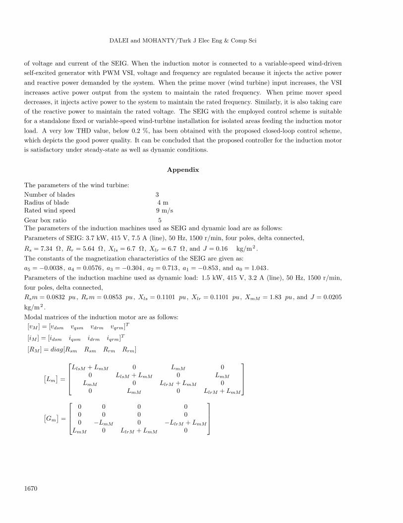
Appendix
The parameters of the wind turbine:
Number of blades 3Radius of blade 4 mRated wind speed 9 m/s
Gear box ratio 5The parameters of the induction machines used as SEIG and dynamic load are as follows:
Parameters of SEIG: 3.7 kW, 415 V, 7.5 A (line), 50 Hz, 1500 r/min, four poles, delta connected,
Rs = 7.34 Ω, Rr = 5.64 Ω, Xls = 6.7 Ω, Xlr = 6.7 Ω, and J = 0.16 kg/m2 .
The constants of the magnetization characteristics of the SEIG are given as:
a5 = −0.0038, a4 = 0.0576, a3 = −0.304, a2 = 0.713, a1 = −0.853, and a0 = 1.043.
Parameters of the induction machine used as dynamic load: 1.5 kW, 415 V, 3.2 A (line), 50 Hz, 1500 r/min,
four poles, delta connected,
Rsm = 0.0832 pu , Rrm = 0.0853 pu , Xls = 0.1101 pu , Xlr = 0.1101 pu , XmM = 1.83 pu , and J = 0.0205
kg/m2 .
Modal matrices of the induction motor are as follows:
[vM ] = [vdsm vqsm vdrm vqrm]T
[iM ] = [idsm iqsm idrm iqrm]T
[RM ] = diag[Rsm Rsm Rrm Rrm]
[Lm
]=
LlsM + LmM 0 LmM 0
0 LlsM + LmM 0 LmM
LmM 0 LlrM + LmM 00 LmM 0 LlrM + LmM
[Gm
]=
0 0 0 00 0 0 00 −LmM 0 −LlrM + LmM
LmM 0 LlrM + LmM 0
1670

DALEI and MOHANTY/Turk J Elec Eng & Comp Sci
Nomenclature
ρ Specific density of air in kg/m3
r Radius of wind turbine in mπr2 Swept area of the bladesCP Performance coefficient of the wind
turbinevω Wind velocity in m/sωT Rotational speed of wind turbineωT r Linear speed at the tip of the blade of
the turbined and q Direct and quadrature axess and r Stator and rotor variables, respectivelyl Leakage componentv and i Instantaneous voltage and current,
respectivelyim and Lm Magnetizing current and magnetizing
inductance, respectivelyr and L Resistance and inductance
ωr Electrical rotor speed of SEIGTdrive and Te Mechanical input torque and
electromagnetic torque of the SEIG,respectively
J and P Moment of inertia and number ofpoles of generator, respectively
ied and ieq Current through the excitationcapacitor in d and q axes, respectively
Ced and Ceq Excitation capacitor valuesin d and q axes, respectively
vm Output voltage of SEIGTL Load torque of induction motorTeM Electromagnetic torque of induction
motorJM Moment of inertia of induction motorPM Number of poles of induction motorωrM Electrical speed of the induction motor
References
[1] Bansal RC, Bhatti TS, Kothari DP. A bibliographical survey on induction generators for application of non -
conventional energy systems. IEEE T Energy Conver 2003; 18: 433–439.
[2] Rahim AH, Alam MA, Kadlawala MF. Dynamic performance improvement of an isolated wind turbine induction
generator. Comput Electr Eng 2009; 35: 594–607.
[3] Seyoum D, Grantham C, Rahman MF. The dynamic characteristics of an isolated generator driven by a wind
turbine. IEEE T Ind Appl 2003; 39: 936–944.
[4] Murthy SS, Malik OP, Tandon AK. Analysis of self-excited induction generators. IEE Proc-C 1982; 129: 260–265.
[5] Lopes LAC, Almedia RG. Wind driven self-excited induction generator with voltage and frequency regulated by a
reduced rating voltage source inverter. IEEE T Energy Conver 2006; 21: 297–304.
[6] Geng H, Xu D, Wuare B. Direct voltage control for a stand-alone wind-driven self-excited induction generator with
improved power quality. IEEE T Power Electr 2011; 26: 632–641.
[7] Kassem AM. Robust voltage control of a stand alone wind energy conversion system based on functional mode
predictive approach. Int J Elec Power 2012; 41: 124–132.
[8] Deraz SA, Kader FEA. A new control strategy for a stand-alone self-excited induction generator driven by a variable
speed wind turbine. Renew Energ 2013; 51: 263–273.
[9] Palwalia DK, Singh SP. Digital signal processor based fuzzy voltage and frequency regulator for self-excited induction
generator. Electr Pow Comp Sys 2010; 38: 309–324.
[10] Pucci M, Cirrincione M, Lee H. Neural MPPT control of wind generators with induction machines without speed
sensors. IEEE T Ind Electron 2011; 58: 37–47.
[11] Wang L, Lee CH. Long shunt and short shunt connections on dynamic performance of a SEIG feeding an induction
motor load. IEEE T Energy Conver 2000; 15: 602–608.
[12] Singh SP, Jain SK, Sharma J. Voltage regulation optimization of compensated self-excited induction generator with
dynamic load. IEEE T Energy Conver 2004; 19: 724–732.
[13] Singh B, Singh M. Transient performance of series compensated three phase self excited induction generator feeding
dynamic loads. IEEE T Energy Conver 2010; 46: 1271–1280.
1671
DALEI and MOHANTY/Turk J Elec Eng & Comp Sci
[14] Chauhan YK, Jain SK, Singh B. Operating performance of static series compensated three-phase self-excited
induction generator. Int J Elec Power 2013; 49: 137–148.
[15] Perumal BV, Chatterjee JK. Voltage and frequency control of a standalone brushless wind electric generation using
generalized impedance controller. IEEE T Energy Conver 2008; 23: 622–640.
[16] Krause PC. Analysis of Electric Machinery. New York, NY, USA: McGraw Hill, 1987.
[17] Idjdarene K, Rekioua D, Rekioua T, Tounzi A. Performance of an isolated induction generator under unbalanced
loads. IEEE T Energy Conver 2010; 25: 303–311.
[18] Dalei J, Mohanty KB. A novel method to determine minimum capacitance of the self-excited induction generator.
In: IEEE Tech Symposium; 28 February– 2 March 2014; Kharagpur, India; pp. 408–413.
[19] Jain SK, Sharma JD, Singh SP. Transient performance of three-phase self excited induction generator during
balanced and unbalanced faults. IEE Proc-C 2002; 149: 50–57.
1672
![Analysis of a High Phase Self Excited Induction Generatoran extension of that adopted in [13] for the modeling of 3 phase SEIG in stationary reference frame. For this purpose the ...](https://static.fdocuments.in/doc/165x107/5f6ff025635f3b29ce4b94b8/analysis-of-a-high-phase-self-excited-induction-generator-an-extension-of-that-adopted.jpg)