PERFORMANCE ANALYSIS OF FACT DEVICES UNDER …ijrrest.org/issues/ijrrest_vol-4_issue-2_010.pdf ·...
6
IJRREST INTERNATIONAL JOURNAL OF RESEARCH REVIEW IN ENGINEERING SCIENCE & TECHNOLOGY (ISSN 2278–6643) VOLUME-4, ISSUE-2, June - 2015 IJRREST, ijrrest.org 49 | Page PERFORMANCE ANALYSIS OF FACT DEVICES UNDER VARIOUS LOAD CONFIGURATIONS 1 Deepak Kumar, 2 Satish Kumar 1 Scholar, RPIIT, Karnal, Haryana, India. Email: [email protected] 2 Assistant Professor, RPIIT, Karnal, Haryana, India. Email: [email protected] Abstract— Modern power system consists of many interconnected generating stations and load centres. So the consumers look for the reliability and quality of power supply. Power quality is one of the biggest problems in the present day. It deals with the problems of voltage sag, voltage flicker, power swing, distortion etc. which can be improved by using the FACTS devices. DVR, DSTATCOM, and UPQC are the devices used for the improvement. These devices have quick response and high reliability. The objective of this paper is to develop Simulink model of DSTATCOM, UPQC and DVR. It is then simulated the performance at different load configurations such as three phase distribution network, dynamic load and DTC induction motor drives. The PI controller is used with the d-q theory to analyse the performance at series, shunt and combined series shunt compensators. Keyword— DTC, UPQC, PI Controller, Fact Devices, Modern Power System. 1. INTRODUCTION From the last few years, in the power industry during the last few years the term power quality has become one of the most common expressions. It is observed that there is countless number of phenomena of power quality in electric power systems. Although this type of disturbances has always occurred in the systems, so the greater attention has recently been dedicated to minimizing their effects to the end users. In the past, it can be said that power quality the concepts and reliability were very similar because the amount of power electronics components was negligible and the loads were mostly linear. The loads were typically lighting, heating, and motors, these loads are not very sensitive to voltage deviations. Moreover, the loads were maximum or minimum isolated from each other and automation process was almost non-existent. These loads were not making the resume if there is any interruption in the process. Power quality has been a topic of great interest. Several issues triggered interest in monitoring and improvement of power quality. The power quality include all possible situations in which the waveform of the supply voltage or load current deviate from the sinusoidal waveform. In all three phases of a three-phase structure the voltage and current should be ideal i.e. at regulated frequency with the amplitude corresponding to the rated Root Mean Square value. The problems of power quality are steady state deviations, such as harmonics and flicker, as well as impulsive and oscillatory transients, voltage sags, short interruptions. On the cause basis, one can easily differentiate, between disturbances linked to the quality of the supply voltage and are interrelated to the quality of the current taken by the load. The main responsibilities of a utility system are to supply ideal electric power with regulated magnitudes and frequency for the customers at the points of common coupling (PCC). Although the voltage generated by the generated synchronous machines in power plants are almost sinusoidal, but there are some unsighted conditions such as short circuit faults, lightning and non-linear loads cause the deviation in voltage and current, some oscillations transient and disturbances . With the advancement of the technology, the industries growing their technology to make the system completely automated. For the automation process the power electronic devices are mostly used in the system which causes fluctuations in voltage, current harmonics and distortion in voltage waveforms, and short circuits faults result in voltage sags and swells. The other electronics devices are sensitive and unprotected to power quality disturbances such as computers, microcontrollers and hospital equipment and their proper operation depends on the quality of the voltage that is supplied to them. For improving the quality and to make the system reliable the only possibility is an uninterrupted flow of power at proper voltage and frequency levels. So the FACTs and customer power devices are used in the electrical system to improve the power quality of the electrical power. These devices we are capable to reduce the problems faced to power quality. There are number of Custom Power devices include Active Power Filters (APF), Surge Arresters (SA). Static VAR Compensator, Dynamic Voltage Restorer, Distribution Series Capacitors, Distribution Static synchronous Compensators and Uninterruptible Power Supplies, Unified power quality conditioner these devices are designed for the protection of the transmission line, but at present more attention is on the distribution system. DSTATCOM are used in the distribution system. The other devices are, DVR and UPQC. A DSTATCOM is a shunt compensator which is connected in shunt at PCC to protect critical loads. The DSTATCOM is an effectible device to reduce current variations and harmonics from the distribution network. The DVR is the series compensator to reduce voltage dip or fluctuations and the UPQC is the combination of series and shunt compensator to protect the system for both the harmonics and the voltage problems. The harmonics current is generated by the nonlinear loads that can be at other locations in the power system and ultimately return back to the source. Therefore, the harmonic current produces harmonic voltages throughout the power systems. Many techniques have been employed to maintain the harmonic voltages and currents within the proposed levels.
Transcript of PERFORMANCE ANALYSIS OF FACT DEVICES UNDER …ijrrest.org/issues/ijrrest_vol-4_issue-2_010.pdf ·...

IJRREST
INTERNATIONAL JOURNAL OF RESEARCH REVIEW IN ENGINEERING SCIENCE & TECHNOLOGY
(ISSN 2278–6643)
VOLUME-4, ISSUE-2, June - 2015
IJRREST, ijrrest.org 49 | P a g e
PERFORMANCE ANALYSIS OF FACT DEVICES UNDER VARIOUS LOAD
CONFIGURATIONS
1Deepak Kumar,
2Satish Kumar
1Scholar, RPIIT, Karnal, Haryana, India. Email: [email protected]
2Assistant Professor, RPIIT, Karnal, Haryana, India. Email: [email protected]
Abstract— Modern power system consists of many interconnected generating stations and load centres. So the consumers look for the
reliability and quality of power supply. Power quality is one of the biggest problems in the present day. It deals with the problems of voltage
sag, voltage flicker, power swing, distortion etc. which can be improved by using the FACTS devices. DVR, DSTATCOM, and UPQC are the
devices used for the improvement. These devices have quick response and high reliability. The objective of this paper is to develop Simulink
model of DSTATCOM, UPQC and DVR. It is then simulated the performance at different load configurations such as three phase
distribution network, dynamic load and DTC induction motor drives. The PI controller is used with the d-q theory to analyse the
performance at series, shunt and combined series shunt compensators.
Keyword— DTC, UPQC, PI Controller, Fact Devices, Modern Power System.
1. INTRODUCTION
From the last few years, in the power industry during the
last few years the term power quality has become one of
the most common expressions. It is observed that there is
countless number of phenomena of power quality in
electric power systems. Although this type of disturbances
has always occurred in the systems, so the greater
attention has recently been dedicated to minimizing their
effects to the end users. In the past, it can be said that
power quality the concepts and reliability were very
similar because the amount of power electronics
components was negligible and the loads were mostly
linear. The loads were typically lighting, heating, and
motors, these loads are not very sensitive to voltage
deviations. Moreover, the loads were maximum or
minimum isolated from each other and automation
process was almost non-existent. These loads were not
making the resume if there is any interruption in the
process. Power quality has been a topic of great interest.
Several issues triggered interest in monitoring and
improvement of power quality. The power quality include
all possible situations in which the waveform of the
supply voltage or load current deviate from the sinusoidal
waveform. In all three phases of a three-phase structure
the voltage and current should be ideal i.e. at regulated
frequency with the amplitude corresponding to the rated
Root Mean Square value. The problems of power quality
are steady state deviations, such as harmonics and flicker,
as well as impulsive and oscillatory transients, voltage
sags, short interruptions. On the cause basis, one can
easily differentiate, between disturbances linked to the
quality of the supply voltage and are interrelated to the
quality of the current taken by the load. The main
responsibilities of a utility system are to supply ideal
electric power with regulated magnitudes and frequency
for the customers at the points of common coupling
(PCC). Although the voltage generated by the generated
synchronous machines in power plants are almost
sinusoidal, but there are some unsighted conditions such
as short circuit faults, lightning and non-linear loads cause
the deviation in voltage and current, some oscillations
transient and disturbances . With the advancement of the
technology, the industries growing their technology to
make the system completely automated. For the
automation process the power electronic devices are
mostly used in the system which causes fluctuations in
voltage, current harmonics and distortion in voltage
waveforms, and short circuits faults result in voltage sags
and swells. The other electronics devices are sensitive
and unprotected to power quality disturbances such as
computers, microcontrollers and hospital equipment
and their proper operation depends on the quality of
the voltage that is supplied to them.
For improving the quality and to make the system reliable
the only possibility is an uninterrupted flow of power at
proper voltage and frequency levels. So the FACTs and
customer power devices are used in the electrical system
to improve the power quality of the electrical power.
These devices we are capable to reduce the problems
faced to power quality. There are number of Custom
Power devices include Active Power Filters (APF), Surge
Arresters (SA). Static VAR Compensator, Dynamic
Voltage Restorer, Distribution Series Capacitors,
Distribution Static synchronous Compensators and
Uninterruptible Power Supplies, Unified power quality
conditioner these devices are designed for the protection
of the transmission line, but at present more attention is
on the distribution system. DSTATCOM are used in the
distribution system. The other devices are, DVR and
UPQC. A DSTATCOM is a shunt compensator which is
connected in shunt at PCC to protect critical loads. The
DSTATCOM is an effectible device to reduce current
variations and harmonics from the distribution network.
The DVR is the series compensator to reduce voltage dip
or fluctuations and the UPQC is the combination of series
and shunt compensator to protect the system for both the
harmonics and the voltage problems. The harmonics
current is generated by the nonlinear loads that can be at
other locations in the power system and ultimately return
back to the source. Therefore, the harmonic current
produces harmonic voltages throughout the power
systems. Many techniques have been employed to
maintain the harmonic voltages and currents within the
proposed levels.

IJRREST
INTERNATIONAL JOURNAL OF RESEARCH REVIEW IN ENGINEERING SCIENCE & TECHNOLOGY
(ISSN 2278–6643)
VOLUME-4, ISSUE-2, June - 2015
IJRREST, ijrrest.org 50 | P a g e
(i) By designing of High power quality equipment,
(ii) Cancellation of harmonics,
(iii) Dedicated line or transformer,
(iv) Harmonic filters (passive, active and hybrid) and
custom power devices such as active power line
conditioner (APLC), DVR, DSTATCOM and
Unified Power Quality Conditioners.
(v) Capacitor banks optimal placement and sizing,
(vi) De-rating of power system devices.
From the literature review, it is observed that field of
power quality and custom power devices such as DVR,
DSTATCOM and UPQCs plays an important role in
power system. It is very important to make the power
supply reliable for the end users. For these custom power
devices there are different types of controlling fuzzy,
hysteresis, PID, and PI controller reported in literature to
compensate various power quality problems. Different
types of custom power devices are used to improve the
power quality and to maintain ideal voltage and current
profile. Utility is responsible for maintaining ideal voltage
profile supplied to the consumers, while for maintaining
ideal current profile at the PCC consumers are
responsible. In the industrial system, dynamic loads and
Induction motor drive causes fluctuations and degrade the
power quality. In order to improve the quality of power,
custom power devices (DSTATCOM, DVR and UPQC)
have been used. The results are obtained by using
MATLAB/ SIMULINK Models.
The main objectives of the thesis are to develop simulink
model for DSTATCOM, DVR and UPQC for the
enhancement of power quality in high power distribution
network consisting of industrial drive and Dynamic load.
The effectiveness of these FACTS devices in solving the
power quality problems has been proved through
simulations, model development and analysis. Research
has been carried out to achieve the above mentioned
objectives of the proposed work.
2. METHODOLGY
For the improvement in the performance of distribution
system, the FACTS Device (D-STATCOM, DVR and
UPQC) was inserted to the distribution system. We are
using MATLAB simulink version R2010a to design the
model. The test system consists of a 440kV or 240 kV ,
at 40Hz, 50Hz and 60 Hz transmission system,
represented by a Thevenin equivalent, feeding into the
primary side of a 2-winding 3 phase transformer
connected in Y/Y, 440/440 kV. For the energy storage of
D-STATCOM a dc source is connected.
For the testing a dynamic load and a DTC motor are
connected at the load point. This Three-Phase Dynamic
Load implements a three-phase, three-wire dynamic load
with varying active power P and reactive power Q as
function of positive-sequence voltage. We introduced
three phase fault with transition time from 0.3s to 0.5s. A
two-level D-STATCOM is connected to the system to
provide instantaneous voltage compensation whereas
DVR provides current support and the UPQC provides
both type of compensation at the load point. Model
Simulations and Results for THD Total harmonic
distortion, or THD, is the summation of all harmonic
components of the Voltage or current waveform
compared against the fundamental component of the
voltage or current wave:
Power factor (PF) is defined as the ratio between true
power and the apparent power, i.e.
The relationship between PF and THD for non- linear
loads can be determined by,
The PWM (Pulse Width Modulation) generates pulses for
carrier-based, self-commutated IGBTs, GTOs or FETs
bridges. Arms are selected on the bases of number of
bridge selected in the "Generator Mode" parameter. The
PI controller is used to control the PWN modulation. This
is using Park transformation for input and output signal
conversion from dq0 reference frame to abc reference
frame.
3. dq0toabc TRANSFORMATION
The process of conversion from the actual coil of machine
itself to the equivalent d-axis and q-axis pf the generalized
machine or vice-versa is known as the transformation.
Perform Park transformation from dq0 reference frame to
abc reference frame. A discrete version of this block is
available in the Extras/Discrete Measurements library.
The dq0_to_abc Transformation block performs the
reverse of the so-called Park transformation, which is
commonly used in three-phase electric machine models. It
transforms three quantities (direct axis, quadratic axis, and
zero-sequence components) expressed in a two-axis
reference frame back to phase quantities. The following
transformation is used:
Where,
w= rotation speed (rad/s) of the rotating frame.
Input 1 contains the vectorized signal of
components
Input 2 must contain a two
dimension signal, where w is the rotation speed of the
reference frame.
Output is a vectorized signal containing the three
phase sinusoidal quantities. The

IJRREST
INTERNATIONAL JOURNAL OF RESEARCH REVIEW IN ENGINEERING SCIENCE & TECHNOLOGY
(ISSN 2278–6643)
VOLUME-4, ISSUE-2, June - 2015
IJRREST, ijrrest.org 51 | P a g e
transformation is the same for the case of a three-
phase current; you simply replace the
variables with the
variables.
The dq0_to_abc Transformation block is used in the
model of the Synchronous Machine block where the stator
quantities are referred to the rotor. The machine consists
of a stationary field winding at the direct axis, and the
rotator armature at the q-axis. These are at right axis to
each other. For the transformation the magnitude and
direction of mmf setup by the three phase current ia, ib, ic
and the two coil currents ids, iqs is identical. The Park
transformation then eliminates time-varying inductances
by referring the stator and rotor quantities to a fixed or
rotating reference frame. The three phase armature
current ia, ib, ic in three phase winding produced rotating
magnetic field and the same is achieved by two axis dq
armature winding. The Id and Iq currents represent the
two DC currents flowing in the two equivalent rotor
windings (d winding on the same axis as the field
winding, and q winding in quadratic) producing the same
flux as the stator Ia, Ib, and Ic currents. This block
transforms three quantities (direct axis, quadrature axis
and zero-sequence components) expressed in a two axis
reference frame back to phase quantities.
3.1 Inputs and Outputs
dq0: Connect to the first input a vectorized signal
containing the sequence components to be
converted.
sin_cos: Connect to the second input a vectorized
signal containing the values,
where ω is the rotation speed of the reference frame.
abc: The output is a vectorized signal containing the
three-phase sinusoidal quantities [A B C]
4. SIMULATION AND RESULTS
In this work, the role of custom power device
(DSTATCOM) is analyzed:
Distribution network having DTC motor as non-linear
load
Dynamic load is also placed with DTC motor load
Compensation is analyzed over 3-phase ground fault
Synchronous Reference Frame(SRF) theory has been
implemented in both series and shunt compensator
Controlling is done through PI controller
4.1 Dynamic Load
The Dynamic Load block implements a three-phase,
three-wire dynamic load whose active power P and
reactive power Q vary as function of positive-sequence
voltage. Negative- and zero-sequence currents are not
simulated. The three load currents are therefore balanced,
even under unbalanced load voltage conditions. The load
impedance is kept constant if the terminal voltage V of the
load is lower than a specified value Vmin. When the
terminal voltage is greater than the Vmin value, the active
power P and reactive power Q of the load vary as follows:
Where,
is the initial positive sequence voltage.
and are the initial active and reactive powers at
the initial voltage .
is the positive-sequence voltage.
are exponents (usually between 1 and 3)
controlling the nature of the load.
are time constants controlling the
dynamics of the active power P.
are time constants controlling the
dynamics of the reactive power Q.
Table I
Simulink model parameters S.No. SYSTEM ELEMENTS PARAMETERS
1 SOURCE 3-Phase, 440V, 50Hz
2 Inverter Parameter IGBT based, 3- arm, 6-Pulse,
Carrier Frequency=1080 Hz ,
Sample Time= 5 µs
3 PI Controller Kp= 0.5,K i =100
4 Transformer1 440/440V Y/Y
5 Injection Transformer 440/440-440 V Y/Y
6 DTC motor load 225MVA
7 Dynamic load P0=50e3W, Q0=25e3Var
5. SIMULINK MODELS
Figure. 5.1: Simulink Model of UPQC
IJRREST
INTERNATIONAL JOURNAL OF RESEARCH REVIEW IN ENGINEERING SCIENCE & TECHNOLOGY
(ISSN 2278–6643)
VOLUME-4, ISSUE-2, June - 2015
IJRREST, ijrrest.org 52 | P a g e
Figure. 5.2: Source Voltage/Current, Load
Voltage/Current Waveform of DSTATCOM
DVR
Figure. 5.3: Source Voltage/Current, Load
Voltage/Current Waveform of DVR OPEN UPQC
Figure. 5.4: Source Voltage/Current, Load
Voltage/Current Waveform of UPQC
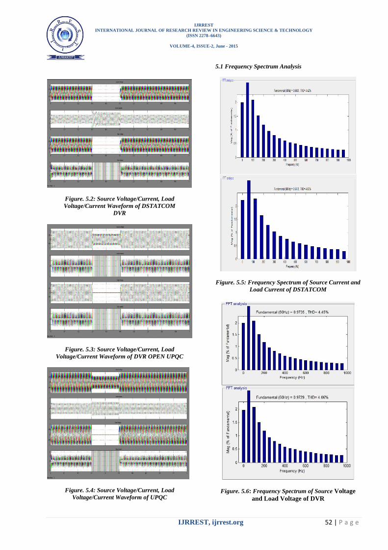
5.1 Frequency Spectrum Analysis
Figure. 5.5: Frequency Spectrum of Source Current and
Load Current of DSTATCOM
Figure. 5.6: Frequency Spectrum of Source Voltage
and Load Voltage of DVR

IJRREST
INTERNATIONAL JOURNAL OF RESEARCH REVIEW IN ENGINEERING SCIENCE & TECHNOLOGY
(ISSN 2278–6643)
VOLUME-4, ISSUE-2, June - 2015
IJRREST, ijrrest.org 53 | P a g e
Figure. 5.7: Frequency Spectrum of Source Current and
Load Current of UPQC
Figure. 5.8: Frequency Spectrum of Source Voltage and
Load Voltage of UPQC
6. CONCLUSIONS
This thesis work is based on the simulation modeling of
FACTS devices (DSTATCOM, DVR AND UPQC).These
custom power devices has been used for the improvement
of power quality problems by connecting them in series,
shunt, and series-shunt compensators respectively. Further
analysis has been done by comparing their performances.
In this paper a performance analysis of DSTATCOM,
DVR and UPQC is presented. These devices are effective
device for current harmonics and voltage sags and dip.
The voltage sags on sensitive equipment is very effective.
Therefore, DVR is used as an efficient solution because it
has low cost, small size, and fast dynamic response. The
simulation results show clearly the performance of a DVR
in mitigating voltage sags and swells. The DVR handles
both balanced and unbalanced situations without any
difficulties and injects the appropriate voltage component
to correct rapidly any anomaly in the supply voltage to
keep the load voltage balanced and constant at the
nominal value.
DSTATCOM, DVR and UPQC are proved that these
devices can compensate the deviation of voltage and
current. By using the different schematic circuits with the
controlling technique the compensation is achieved.
In the industries, different types of loads are introduced to
the transmission system which introduced different
deviations as described in the above chapter. If we use
these loads at different voltage or frequency level there
capacity of introducing the deviation is different. So the
FACTS devices are studied at their different levels of
voltage and frequency of loads. With the change in the
level of these two quantities, the performance of the
custom power devices will also change. The performance
of the DSTATCOM, DVR and UPQC is described in the
Table II.
TABLE II
Performance Analysis
Name of
FACTs
devices
Compen
sator
type
Harmonics
type
Voltage
level of
devices
frequ
ency
Total
harmonic
distortion
(THD)
DSTATC
OM
Series Current
harmonics
240v
40Hz
50Hz
60HZ
4.16%
4.42%
4.68%
440v
40Hz
50HZ
60HZ
4.15%
4.41%
4.68%
DVR Shunt Voltage
harmonics
240v 40Hz
50Hz
60Hz
5.08%
5.48%
5.76%
440v 40Hz
50Hz
60Hz
4.61%
4.93%
5.10%
UPQC Series-
Shunt
Voltage
current
440v 50Hz 4.06%
50.48%
The presented work can be extended in other following
related areas:The more advanced controllers such as fuzzy
controller, artificial neutral network, AUPF, ISCT,
AGCT, IGCT theories can also be used with UPQC to
make the system more effective. Effectiveness UPQC can

IJRREST
INTERNATIONAL JOURNAL OF RESEARCH REVIEW IN ENGINEERING SCIENCE & TECHNOLOGY
(ISSN 2278–6643)
VOLUME-4, ISSUE-2, June - 2015
IJRREST, ijrrest.org 54 | P a g e
be investigated by multi-level converters. Effectiveness of
Z-source inverters can be investigated for various CP
devices.
REFERENCES
[1] S.V. Ravi Kumar and S. Siva Nagaraju, “Simulation of D-
Statcom and DVR in Power Systems”, ARPN Journal of
Engineering and Applied Sciences vol. 2, no. 3, 2007. [2] ArindamGhosh and Gerard Ledwich, “Load Compensating D-
STATCOM in Weak AC Systems”, IEEE Transactions on
Power Delivery, vol.18, pp.1302 – 1309, 2003. [3] Bhim Singh, AlkaAdya, A.P. Mittal, J.R.P Gupta, “Power
Quality Enhancement with D-STATCOM for Small Isolated
Alternator feeding Distribution System”, Conference on Power Electronics and Drive Systems 2005, (PEDS 2005),
vol.1, pp. 274-279, 2005.
[4] Dinesh Kumar and Rajesh, “Modeling, Analysis and Performance of a D-STATCOM for Unbalanced and Non-
Linear Load”, IEEE/PES Conference on Transmission and
Distribution conference and Exhibition Asia and pacific, Publication, pp. 1 – 6, 2005.
[5] WalmirFreitas, Andre Morelato, WilsunXuandFujio Sato,
“Impacts of AC Generators and D-STATCOM Devices on the Dynamic Performance of Distribution Systems”,
IEEETransactions on Power Delivery, pp. 1493 – 1501,2005.
[6] Bhim Singh, AlkaAdya , A.P. Mittal and J.R.P Gupta, “Modelling and Control of D-STATCOM for Three-Phase,
Four-Wire Distribution Systems”, Conference on Industry
Applications, vol. 4, pp. 2428 - 2434, 2005. [7] M. G. Molina and P. E. Mercado, “Dynamic Modelling and
Control Design of D-STATCOM with Ultra-Capacitor Energy
Storage for Power Quality Improvements”, IEEE/PES Conference on Transmission and Distribution conference and
Exposition: Latin America, pp. 1 – 8, 2008.
[8] P. M. Meshram, B.Y.Bagde, R.N.Nagpure, “A Novel DFACTS Device for the Improvement of Power Quality of the
Supply”,2nd International Conference on Electrical
Engineering and Electronics, Computer, Telecommunications and Information Technology (ECTI-CON 2005), vol.1, pp.
775-778,2005.
[9] M. G. Molina, P. E. Mercado, “Control Design and Simulation of D-STATCOM with Energy Storage for Power
Quality Improvements”, IEEE/PES Conference on
Transmission and Distribution Conference and Exposition Latin America, Venezuela,pp.1 - 7, 2006.
[10] Bhim Singh, AlkaAdya, A.P.Mittal and J.R.P. Gupta,
“Modelling, Design and Analysis of Different Controllers for D-STATCOM”, IEEE Power India Conference on Power
system technology and, 2008, pp. 1 -8, 2008.
[11] AfshinLashkarAra and Seyed Ali NabaviNiaki, “Comparison of The Facts Equipment Operation In Transmission And
Distribution Systems”17th International Conference on
Electricity Distribution Barcelona, vol.2, pp. 44,2003. [12] Arindam Chakraborty,1 Shravana K.Musunuri,2 Anurag K.
Srivastava,3 and Anil K. Kondabathini4 “Integrating
STATCOM and Battery Energy Storage System for Power System Transient Stability: A Review and Application”
[13] Z. Yang, C. Shen, L. Zhang, M. L. Crow, and S. Atcitty,
“Integration of a Statcom and battery energy storage,” IEEE Transactions on Power Systems, vol. 16, no. 2, pp. 254–260,
2001. [14] A. Arsoy, Y. Liu, S. Chen, Z. Yang, M. L. Crow, and P. F.
Ribeiro, “Dynamic performance of a static synchronous
compensator with energy storage,” in Proceedings of the IEEE Power Engineering Society Winter Meeting, pp. 605–
610, February 2001.
[15] Hongfa Ding, ShuShuangyan, DuanXianzhong and Gao Jun (2002), „A Novel Dynamic Voltage Restorer and its
Unbalanced Control Strategy based on Space Vector PWM‟,
Electrical Power and Energy Systems, No. 24, pp. 693-699.
[16] Nguyen P. T. and Tapan K. Saha (2004), „DVR against Balanced and Unbalanced Voltage Sags: Modelling and
Simulation‟, Proceedings of the IEEE Industrial Electronics
Conference, pp. 1-6. [17] Chris Fitzer, Mike Barnes and Peter Green (2004), „Voltage
Sag Detection Technique for a Dynamic Voltage Restorer‟,
IEEE Transactions on Industry Applications, Vol. 40, No. 1, pp. 203-212.
[18] Kaifei Wang, Fang Zhuo, Yandong Li, Xu Yang and Zhaoan
Wang (2004), „Three-phase Four-wire Dynamic Voltage Restorer Based on a new SVPWM Algorithm‟, Proceedings of
the 35th Annual IEEE Power Electronics Specialists
Conference, pp. 3877-3882. [19] Hyosung Kim and Seung-Ki Sul (2005), „Compensation
Voltage Control in Dynamic Voltage Restorers by use of Feed
Forward and State Feedback Scheme‟, IEEE Transactions on Power Electronics, Vol. 20, No. 5, pp. 1169-1177.