PERFORMANCE ANALYSIS OF FACTS (D-STATCOM …ijrrest.org/issues/ijrrest_vol-4_issue-3_002.pdf ·...
7
IJRREST INTERNATIONAL JOURNAL OF RESEARCH REVIEW IN ENGINEERING SCIENCE & TECHNOLOGY (ISSN 2278–6643) VOLUME-4, ISSUE-3, November – 2015 IJRREST, ijrrest.org 5 | Page P ERFORMANCE ANALYSIS OF FACTS (D-STATCOM AND DVR) DEVICES Manoj Garg 1 & Rajeev Kumar 2 1 Research Scholar, GIMT, Kurukshetra, Haryana, India 2 Assistant Professor, GIMT, Kurukshetra, Haryana, India Abstract — The Power Quality Analysis aspires to bring out electricity consumers for improved power quality with application of power electronics. The research work involves in-depth analysis of the interaction among loads, power networks and various power quality improvement devices. It ultimately leads to better design of mitigation devices like Dynamic Voltage Restorer (DVR), Distribution Static Synchronous Compensator (DSTATCO M) and Unified Power Quality Conditioner (UPQC) to alleviate various power quality related problems. The main objective of this research work is to develop a model of DVR and DSTATCO M for enhancement of power quality. DVR and DSTATCO M are among the custom power devices that are used as an effective solution for the protection of sensitive loads against voltage disturbances in power distribution system. The efficiency of the FACTS devices depends on the performance of the control technique, which involved in switching the inverters. A comparative analysis of PI controlled DVR and DSTATCOM has been carried out for better power system stability enhancement. The validity of the proposed method and achievement of the desired compensation are confirmed by the re sults of the simulation in Matlab/ Simulink. 1. I NTRO DUC TIO N Power quality is a word that means different things to different inhabitants. Institute of Electrical and Electronic Engineers (IEEE) Standard IEEE1100 defines power quality as, “The conception of powering and grounding sensitive electronic equipment in a manner suitable for the equipment.” As suitable as this description might seem, the drawback of power quality to ―sensitive electronic equipment‖ might be subject to deviation. Electrical equipment susceptible to power quality or more appropriately to need of power quality would fall within an apparently boundless domain. All electrical devices are prone to failure or breakdown when exposed to one or more power quality problems. The electrical device might be an electric motor, a transformer, a generator, a computer, a printer, communication equipment or a home appliance. All of these devices and others react undesirably to power quality issues, depending on the severity of problems. However, nearly everybody accepts that it is a very important aspect of power systems and electric machinery with direct impacts on efficiency, security and reliability. Various sources use the term ―power quality‖ with different meaning. It is used synonymously with ―supply reliability,‖ ―service quality,‖ ―voltage quality,‖ ―current quality,‖ ―quality of supply‖ and ―quality of consumption.‖ Nonlinear loads generate harmonic currents that can promulgate to other locations in the power system and ultimately return back to the source. Therefore, harmonic current promulgation produces harmonic voltages throughout the power systems. Many mitigation techniques have been suggested and employed to maintain the harmonic voltages and currents within proposed levels. 1. Design of High power quality equipment, 2. Cancellation of Harmonics, 3. Dedicated line or transformer, 4. Capacitor banks optimal placement and sizing, 5. Derating of power system devices and 6. Harmonic filters (passive, active and hybrid) and custom power devices such as active power line conditioner (APLC), DVR, DSTATCOM and Unified Power Quality Conditioners. The phenomenon of power quality through application of power electronics is studied in the research work. The aim of the control scheme is to develop Simulink model of DVR and DSATCOM maintain constant voltage magnitude at the point where a sensitive load is connected, under system disturbances. The wide range of power quality disturbances covers sudden, short duration variations, e.g. impulsive and oscillatory transients, voltage sags, short interruptions, as well as steady state deviations, such as harmonics mitigation by using DVR. This research work, specifically examine the use of a power electronic shunt compensator named as DSTATCOM to correct the current drawn from a utility to closely approximate balanced sinusoidal waveforms, without adversely affecting the voltage at the point of common coupling. Thus, adjustment of the feedback gains makes it possible to reduce voltage fluctuation in transient states, when the active filter has the function of combined harmonic damping and voltage regulation. By using UPQC the control scheme of a shunt active power filter must calculate the current reference waveform for each phase of the inverter, maintain the dc voltage constant and generate the inverter gating signals. To correct for the effects of supply voltage distortion, the series compensator is required to inject appropriate harmonic voltages. A novel strategy for the improvement of power quality based on custom power devices the analysis of the results obtained from various techniques
Transcript of PERFORMANCE ANALYSIS OF FACTS (D-STATCOM …ijrrest.org/issues/ijrrest_vol-4_issue-3_002.pdf ·...
IJRREST
INTERNATIONAL JOURNAL OF RESEARCH REVIEW IN ENGINEERING SCIENCE & TECHNOLOGY (ISSN 2278–6643)
VOLUME-4, ISSUE-3, November – 2015
IJRREST, ijrrest.org 5 | P a g e
PERFORMANCE ANALYSIS OF FACTS (D-STATCOM AND DVR) DEVICES Manoj Garg
1 & Rajeev Kumar
2
1Research Scholar, GIMT, Kurukshetra, Haryana, India
2Assistant Professor, GIMT, Kurukshetra, Haryana, India
Abstract— The Power Quality Analysis aspires to bring out electricity consumers for improved power quality with application of power
electronics. The research work involves in -depth analysis of the interaction among loads, power networks and various power quality improvement devices. It ultimately leads to better design of mitigation devices like Dynamic Voltage Restorer (DVR), Distribution Static Synchronous Compensator (DSTATCO M) and Unified Power Quality Conditioner (UPQC) to alleviate various power quality related
problems. The main objective of this research work is to develop a model of DVR and DSTATCO M for enhancement of power quality. DVR and DSTATCO M are among the custom power devices that are used as an effective solution for the protection of sensitive loads against voltage disturbances in power distribution system. The efficiency of the FACTS devices depends on the performance of the control technique, which involved in switching the inverters. A comparative analysis of PI controlled DVR and DSTATCO M has been carried out for better
power system stability enhancement. The validity of the proposed method and achievement of the desired compensation are confirmed by the results of the simulation in Matlab/ Simulink.
1. INTRO DUCTIO N
Power quality is a word that means different things to
different inhabitants. Institute of Electrical and Electronic
Engineers (IEEE) Standard IEEE1100 defines power quality as,
“The conception of powering and grounding sensitive
electronic equipment in a manner suitable for the equipment.”
As suitable as this description might seem, the drawback of power quality to ―sensitive electronic equipment‖ might
be subject to deviation. Electrical equipment susceptible to power quality or more appropriately to need of power
quality would fall within an apparently boundless domain.
All electrical devices are prone to failure or breakdown
when exposed to one or more power quality problems. The electrical device might be an electric motor, a transformer,
a generator, a computer, a printer, communication equipment or a home appliance. All of these devices and
others react undesirably to power quality issues, depending on the severity of problems.
However, nearly everybody accepts that it is a very
important aspect of power systems and electric machinery
with direct impacts on efficiency, security and reliability. Various sources use the term ―power quality‖ with
different meaning. It is used synonymously with ―supply reliability,‖ ―service quality,‖ ―voltage quality,‖ ―current
quality,‖ ―quality of supply‖ and ―quality of consumption.‖
Nonlinear loads generate harmonic currents that can
promulgate to other locations in the power system and ultimately return back to the source. Therefore, harmonic
current promulgation produces harmonic voltages throughout the power systems.
Many mitigation techniques have been suggested and
employed to maintain the harmonic voltages and currents
within proposed levels.
1. Design of High power quality equipment, 2. Cancellation of Harmonics,
3. Dedicated line or transformer,
4. Capacitor banks optimal placement and sizing, 5. Derating of power system devices and
6. Harmonic filters (passive, active and hybrid) and custom power devices such as active power line
conditioner (APLC), DVR, DSTATCOM and Unified Power Quality Conditioners.
The phenomenon of power quality through application of power electronics is studied in the research work. The aim
of the control scheme is to develop Simulink model of DVR and DSATCOM maintain constant voltage
magnitude at the point where a sensitive load is connected, under system disturbances. The wide range of power
quality disturbances covers sudden, short duration variations, e.g. impulsive and oscillatory transients,
voltage sags, short interruptions, as well as steady state
deviations, such as harmonics mitigation by using DVR.
This research work, specifically examine the use of a power electronic shunt compensator named as
DSTATCOM to correct the current drawn from a utility to closely approximate balanced sinusoidal waveforms,
without adversely affecting the voltage at the point of
common coupling.
Thus, adjustment of the feedback gains makes it possible to reduce voltage fluctuation in transient states, when the
active filter has the function of combined harmonic damping and voltage regulation. By using UPQC the
control scheme of a shunt active power filter must
calculate the current reference waveform for each phase of the inverter, maintain the dc voltage constant and generate
the inverter gating signals.
To correct for the effects of supply voltage distortion, the series compensator is required to inject appropriate
harmonic voltages. A novel strategy for the improvement of power quality based on custom power devices the
analysis of the results obtained from various techniques
IJRREST
INTERNATIONAL JOURNAL OF RESEARCH REVIEW IN ENGINEERING SCIENCE & TECHNOLOGY (ISSN 2278–6643)
VOLUME-4, ISSUE-3, November – 2015
IJRREST, ijrrest.org 6 | P a g e
like PI Controller and Fuzzy Logic Controller are
presented.
The main objectives of the research work are to develop
model for DVR for the enhancement of power quality in
electrical power networks. The objective which has been laid down for this work is the development of DVR and
DSTATCOM model simulation model and their performance analysis through simulation.
Research has been carried out to achieve the above
mentioned objectives. The effectiveness of the
DSTATCOM and DVR in solving the power quality problems has been proved through simulations, model
development and analysis.
Custom power devices transient performance observed. Control techniques developed to overcome the problems
related to DC Link voltage deviations.
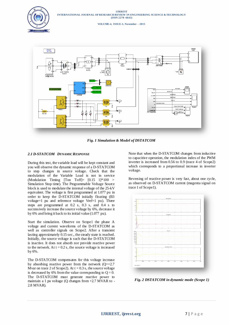
2. D-STATCO M MO DEL DESCRIPTIO N
A Distribution Static Synchronous Compensator (D-STATCOM) is used to regulate voltage on a 25-kV
distribution network. Two feeders (21 km and 2 km) transmit power to loads connected at buses B2 and B3. A
shunt capacitor is used for power factor correction at bus B2. The 600-V load connected to bus B3 through a
25kV/600V transformer represents a plant absorbing continuously changing currents, similar to an arc furnace,
thus producing voltage flicker.
The variable load current magnitude is modulated at a
frequency of 5 Hz so that its apparent power varies approximately between 1 MVA and 5.2 MVA, while
keeping a 0.9 lagging power factor. This load variation will allow you to observe the ability of the D-STATCOM
to mitigate voltage flicker.
The D-STATCOM regulates bus B3 voltage by absorbing
or generating reactive power. This reactive power transfer is done through the leakage reactance of the coupling
transformer by generating a secondary voltage in phase with the primary voltage (network side). This voltage is
provided by a voltage-sourced PWM inverter. When the
secondary voltage is lower than the bus voltage, the D-STATCOM acts like an inductance absorbing reactive
power.
When the secondary voltage is higher than the bus voltage, the D-STATCOM acts like a capacitor generating reactive
power.
The D-STATCOM consists of the following components:
a 25kV/1.25kV coupling transformer which ensures coupling between the PWM inverter and
the network.
a voltage-sourced PWM inverter consisting of two IGBT bridges. This twin inverter configuration
produces fewer harmonic than a single bridge,
resulting in smaller filters and improved dynamic response. In this case, the inverter modulation
frequency is 28*60=1.68 kHz so that the first harmonics will be around 3.36 kHz.
LC damped filters connected at the inverter output. Resistances connected in series with capacitors provide a quality factor of 40 at 60 Hz.
a 10000-microfarad capacitor acting as a DC
voltage source for the inverter
a voltage regulator that controls voltage at bus B3
a PWM pulse generator using a modulation frequency of 1.68 kHz
Anti-aliasing filters used for voltage and current acquisition.
The D-STATCOM controller consists of several functional blocks:
a Phase Locked Loop (PLL). The PLL is synchronized to the fundamental of the transformer
primary voltages.
two measurement systems . Vmeas and Imeas blocks compute the d-axis and q-axis components
of the voltages and currents by executing an abc-dq transformation in the synchronous reference
determined by sin(wt) and cos(wt) provided by the PLL.
an inner current regulation loop. This loop
consists of two proportional-integral (PI) controllers that control the d-axis and q-axis
currents. The controllers outputs are the Vd and Vq voltages that the PWM inverter has to generate. The
Vd and Vq voltages are converted into phase voltages Va, Vb, Vc which are used to synthesize
the PWM voltages. The Iq reference comes from
the outer voltage regulation loop (in automatic mode) or from a reference imposed by Qref (in
manual mode). The Id reference comes from the DC-link voltage regulator.
an outer voltage regulation loop. In automatic
mode (regulated voltage), a PI controller maintains the primary voltage equal to the reference value
defined in the control system dialog box.
a DC voltage controller which keeps the DC link voltage constant to its nominal value (Vdc=2.4 kV).
The electrical circuit is discretized using a sample time
Ts=5 microseconds. The controller uses a larger sample
time (32*Ts= 160 microseconds).
IJRREST
INTERNATIONAL JOURNAL OF RESEARCH REVIEW IN ENGINEERING SCIENCE & TECHNOLOGY (ISSN 2278–6643)
VOLUME-4, ISSUE-3, November – 2015
IJRREST, ijrrest.org 7 | P a g e
Fig. 1 Simulation & Model of DSTATCOM
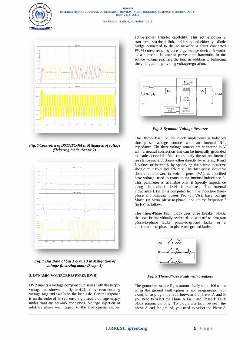
2.1 D-STATCOM DYNAMIC RESPONSE
During this test, the variable load will be kept constant and
you will observe the dynamic response of a D-STATCOM to step changes in source voltage. Check that the
modulation of the Variable Load is not in service
(Modulation Timing [Ton Toff]= [0.15 1]*100 > Simulation Stop time). The Programmable Voltage Source
block is used to modulate the internal voltage of the 25-kV equivalent. The voltage is first programmed at 1.077 pu in
order to keep the D-STATCOM initially floating (B3 voltage=1 pu and reference voltage Vref=1 pu). Three
steps are programmed at 0.2 s, 0.3 s, and 0.4 s to successively increase the source voltage by 6%, decrease it
by 6% and bring it back to its initial value (1.077 pu).
Start the simulation. Observe on Scope1 the phase A
voltage and current waveforms of the D-STATCOM as well as controller signals on Scope2. After a transient
lasting approximately 0.15 sec., the steady state is reached. Initially, the source voltage is such that the D-STATCOM
is inactive. It does not absorb nor provide reactive power
to the network. At t = 0.2 s, the source voltage is increased by 6%.
The D-STATCOM compensates for this voltage increase
by absorbing reactive power from the network (Q=+2.7 Mvar on trace 2 of Scope2). At t = 0.3 s, the source voltage
is decreased by 6% from the value corresponding to Q = 0.
The D-STATCOM must generate reactive power to maintain a 1 pu voltage (Q changes from +2.7 MVAR to -
2.8 MVAR).
Note that when the D-STATCOM changes from inductive
to capacitive operation, the modulation index of the PWM inverter is increased from 0.56 to 0.9 (trace 4 of Scope2)
which corresponds to a proportional increase in inverter voltage.
Reversing of reactive power is very fast, about one cycle,
as observed on D-STATCOM current (magenta signal on
trace 1 of Scope1).
Fig. 2 DSTATCOM in dynamic mode (Scope 1)

IJRREST
INTERNATIONAL JOURNAL OF RESEARCH REVIEW IN ENGINEERING SCIENCE & TECHNOLOGY (ISSN 2278–6643)
VOLUME-4, ISSUE-3, November – 2015
IJRREST, ijrrest.org 8 | P a g e
Fig. 3 controller of DSTATCOM in dynamic mode
(Scope 2)
Fig. 4 Bus data of bus 1 & Bus 3 in dynamic mode
(Scope 3)
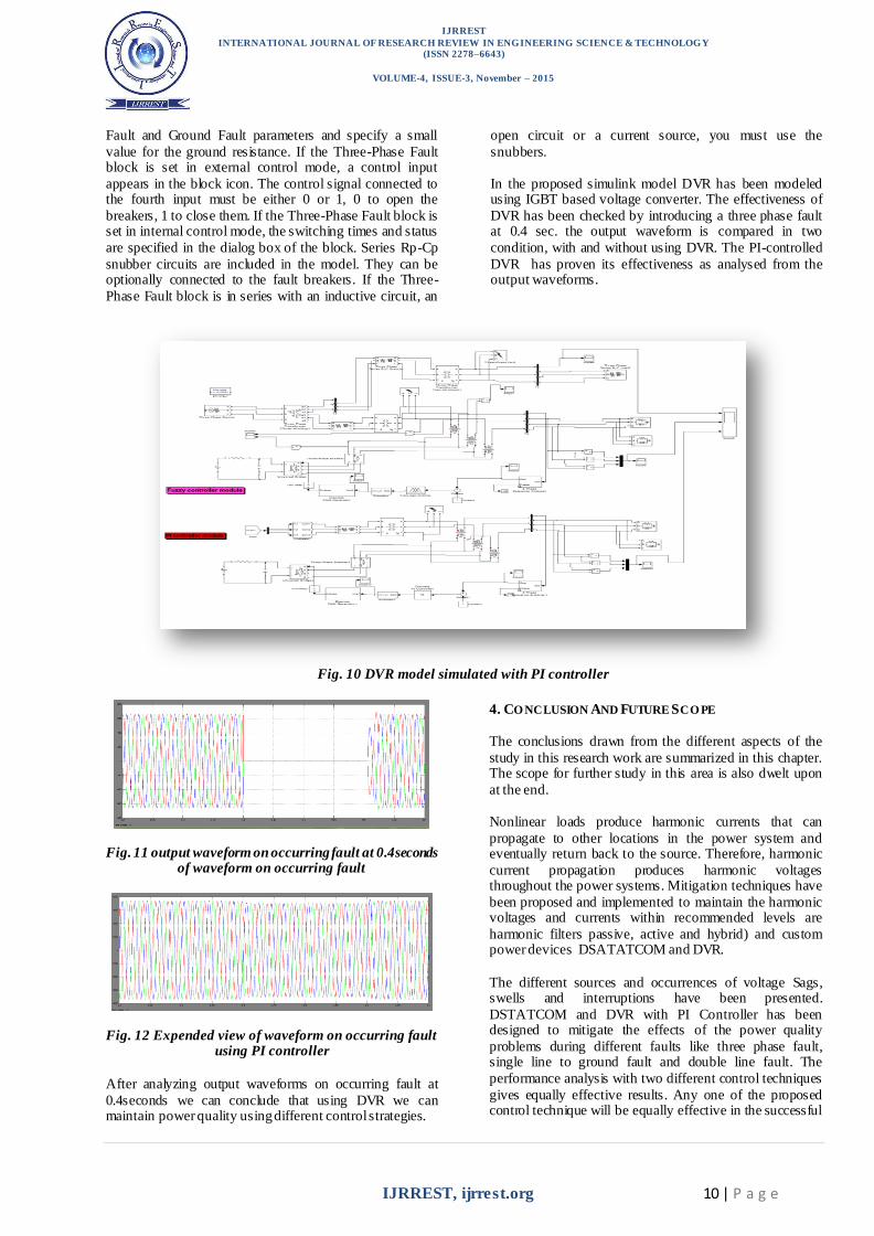
2.2 MITIGATION OF VOLTAGE FLICKER
During this test, voltage of the Programmable Voltage
Source will be kept constant and you will enable modulation of the Variable Load so that you can observe
how the D-STATCOM can mitigate voltage flicker. In the Programmable Voltage Source block menu, change the
"Time Variation of" parameter to "None". In the Variable Load block menu, set the Modulation Timing parameter to
[Ton Toff]= [0.15 1] (remove the 100 multiplication
factor). Finally, in the D-STATCOM Controller, change the "Mode of operation" parameter to "Q regulation" and
make sure that the reactive power reference value Qref (2nd line of parameters) is set to zero. In this mode, the D-
STATCOM is floating and performs no voltage correction.
Run the simulation and observe on Scope3 variations of P
and Q at bus B3 (1st trace) as well as voltages at buses B1 and B3 (trace 2). Without D-STATCOM, B3 voltage
varies between 0.96 pu and 1.04 pu (+/- 4% variation). Now, in the D-STATCOM Controller, change the "Mode
of operation" parameter back to "Voltage regulation" and restart simulation. Observe on Scope 3 that voltage
fluctuation at bus B3 is now reduced to +/- 0.7 %.
The D-STATCOM compensates voltage by injecting a reactive current modulated at 5 Hz (trace 3 of Scope3) and varying between 0.6 pu capacitive when voltage is low and
0.6 pu inductive when voltage is high.
Fig. 5 DSTATCOM in Mitigation of voltage flickering
mode (Scope 1)
IJRREST
INTERNATIONAL JOURNAL OF RESEARCH REVIEW IN ENGINEERING SCIENCE & TECHNOLOGY (ISSN 2278–6643)
VOLUME-4, ISSUE-3, November – 2015
IJRREST, ijrrest.org 9 | P a g e
Fig. 6 Controller of DSTATCOM in Mitigation of voltage
flickering mode (Scope 2)
Fig. 7 Bus Data of bus 1 & bus 3 in Mitigation of
voltage flickering mode (Scope 3)
3. DYNAMIC VO LTAGE RESTO RER (DVR)
DVR injects a voltage component in series with the supply
voltage as shown in figure-4.21, thus compensating voltage sags and swells on the load side. Control response
is on the order of 3msec, ensuring a secure voltage supply
under transient network conditions. Voltage injection of arbitrary phase with respect to the load current implies
active power transfer capability. This active power is
transferred via the dc link, and is supplied either by a diode bridge connected to the ac network, a shunt connected
PWM converter or by an energy storage device. It works as a harmonic isolator to prevent the harmonics in the
source voltage reaching the load in addition to balancing the voltages and providing voltage regulation.
Fig. 8 Dynamic Voltage Restorer
The Three-Phase Source block implements a balanced
three-phase voltage source with an internal R-L impedance. The three voltage sources are connected in Y
with a neutral connection that can be internally grounded or made accessible. You can specify the source internal
resistance and inductance either directly by entering R and
L values or indirectly by specifying the source inductive short-circuit level and X/R ratio The three-phase inductive
short-circuit power, in volts-amperes (VA), at specified base voltage, used to compute the internal inductance L.
This parameter is available only if Specify impedance using short-circuit level is selected. The internal
inductance L (in H) is computed from the inductive three-phase short-circuits power Psc (in VA), base voltage
Vbase (in Vrms phase-to-phase), and source frequency f
(in Hz) as follows:
The Three-Phase Fault block uses three Breaker blocks
that can be individually switched on and off to program
phase-to-phase faults, phase-to-ground faults, or a combination of phase-to-phase and ground faults.
Fig. 9 Three-Phase Fault with breakers
The ground resistance Rg is automatically set to 106 ohms
when the ground fault option is not programmed. For example, to program a fault between the phases A and B
you need to select the Phase A Fault and Phase B Fault block parameters only. To program a fault between the
phase A and the ground, you need to select the Phase A
IJRREST
INTERNATIONAL JOURNAL OF RESEARCH REVIEW IN ENGINEERING SCIENCE & TECHNOLOGY (ISSN 2278–6643)
VOLUME-4, ISSUE-3, November – 2015
IJRREST, ijrrest.org 10 | P a g e
Fault and Ground Fault parameters and specify a small
value for the ground resistance. If the Three-Phase Fault block is set in external control mode, a control input
appears in the block icon. The control signal connected to the fourth input must be either 0 or 1, 0 to open the
breakers, 1 to close them. If the Three-Phase Fault block is set in internal control mode, the switching times and status
are specified in the dialog box of the block. Series Rp-Cp
snubber circuits are included in the model. They can be optionally connected to the fault breakers. If the Three-
Phase Fault block is in series with an inductive circuit, an
open circuit or a current source, you must use the
snubbers.
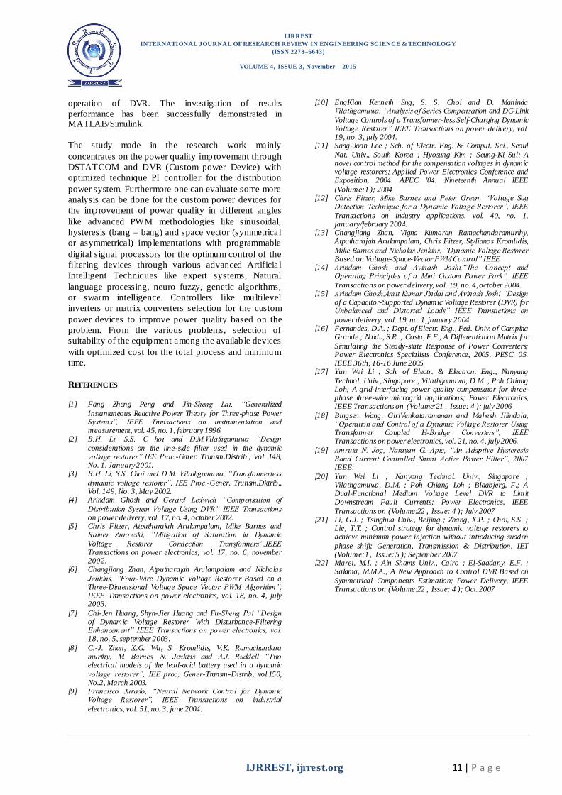
In the proposed simulink model DVR has been modeled using IGBT based voltage converter. The effectiveness of
DVR has been checked by introducing a three phase fault at 0.4 sec. the output waveform is compared in two
condition, with and without using DVR. The PI-controlled
DVR has proven its effectiveness as analysed from the output waveforms.
Fig. 10 DVR model simulated with PI controller
Fig. 11 output waveform on occurring fault at 0.4seconds of waveform on occurring fault
Fig. 12 Expended view of waveform on occurring fault using PI controller
After analyzing output waveforms on occurring fault at
0.4seconds we can conclude that using DVR we can maintain power quality using different control strategies.
4. CO NCLUSION AND FUTURE SCO PE
The conclusions drawn from the different aspects of the
study in this research work are summarized in this chapter. The scope for further study in this area is also dwelt upon
at the end.
Nonlinear loads produce harmonic currents that can
propagate to other locations in the power system and eventually return back to the source. Therefore, harmonic
current propagation produces harmonic voltages throughout the power systems. Mitigation techniques have
been proposed and implemented to maintain the harmonic voltages and currents within recommended levels are
harmonic filters passive, active and hybrid) and custom power devices DSATATCOM and DVR.
The different sources and occurrences of voltage Sags, swells and interruptions have been presented.
DSTATCOM and DVR with PI Controller has been designed to mitigate the effects of the power quality
problems during different faults like three phase fault, single line to ground fault and double line fault. The
performance analysis with two different control techniques
gives equally effective results. Any one of the proposed control technique will be equally effective in the successful
IJRREST
INTERNATIONAL JOURNAL OF RESEARCH REVIEW IN ENGINEERING SCIENCE & TECHNOLOGY
(ISSN 2278–6643)
VOLUME-4, ISSUE-3, November – 2015
IJRREST, ijrrest.org 11 | P a g e
operation of DVR. The investigation of results
performance has been successfully demonstrated in MATLAB/Simulink.
The study made in the research work mainly
concentrates on the power quality improvement through
DSTATCOM and DVR (Custom power Device) with
optimized technique PI controller for the d istribution
power system. Furthermore one can evaluate some more
analysis can be done for the custom power devices for
the improvement of power quality in different angles
like advanced PWM methodologies like sinusoidal,
hysteresis (bang – bang) and space vector (symmetrical
or asymmetrical) implementations with programmable
digital signal processors for the optimum control of the
filtering devices through various advanced Artificial
Intelligent Techniques like expert systems, Natural
language processing, neuro fuzzy, genetic algorithms,
or swarm intelligence. Controllers like multilevel
inverters or matrix converters selection for the custom
power devices to improve power quality based on the
problem. From the various problems, selection of
suitability of the equipment among the availab le devices
with optimized cost for the total process and minimum
time.
REFERENCES
[1] Fang Zheng Peng and Jih-Sheng Lai, “Generalized
Instantaneous Reactive Power Theory for Three-phase Power Systems”, IEEE Transactions on instrumentation and measurement, vol. 45, no. 1, february 1996.
[2] B.H. Li, S.S. C hoi and D.M.Vilathgamuwa “Design
considerations on the line-side filter used in the dynamic voltage restorer” IEE Proc.-Gmer. Trunsm.Distrib., Vol. 148, No. 1. January 2001.
[3] B.H. Li, S.S. Choi and D.M. Vilathgamuwa, “Transformerless
dynamic voltage restorer”, IEE Proc,-Gener. Trunsm.Dktrib., Vol. 149, No. 3, May 2002.
[4] Arindam Ghosh and Gerard Ledwich “Compensation of
Distribution System Voltage Using DVR” IEEE Transactions on power delivery, vol. 17, no. 4, october 2002.
[5] Chris Fitzer, Atputharajah Arulampalam, Mike Barnes and Rainer Zurowski, “Mitigation of Saturation in Dynamic
Voltage Restorer Connection Transformers“,IEEE Transactions on power electronics, vol. 17, no. 6, november 2002.
[6] Changjiang Zhan, Atputharajah Arulampalam and Nicholas
Jenkins, “Four-Wire Dynamic Voltage Restorer Based on a Three-Dimensional Voltage Space Vector PWM Algorithm”, IEEE Transactions on power electronics, vol. 18, no. 4, july 2003.
[7] Chi-Jen Huang, Shyh-Jier Huang and Fu-Sheng Pai “Design of Dynamic Voltage Restorer With Disturbance-Filtering Enhancement” IEEE Transactions on power electronics, vol. 18, no. 5, september 2003.
[8] C.-J. Zhan, X.G. Wu, S. Kromlidis, V.K. Ramachandara murthy, M. Barnes, N. Jenkins and A.J. Ruddell “Two electrical models of the lead-acid battery used in a dynamic
voltage restorer”, IEE proc, Gener-Transm-Distrib, vol.150, No.2, March 2003.
[9] Francisco Jurado, “Neural Network Control for Dynamic Voltage Restorer”, IEEE Transactions on industrial
electronics, vol. 51, no. 3, june 2004.
[10] EngKian Kenneth Sng, S. S. Choi and D. Mahinda Vilathgamuwa, “Analysis of Series Compensation and DC-Link
Voltage Controls of a Transformer-less Self-Charging Dynamic Voltage Restorer” IEEE Transactions on power delivery, vol. 19, no. 3, july 2004.
[11] Sang-Joon Lee ; Sch. of Electr. Eng. & Comput. Sci., Seoul
Nat. Univ., South Korea ; Hyosung Kim ; Seung-Ki Sul; A novel control method for the compensation voltages in dynamic voltage restorers; Applied Power Electronics Conference and Exposition, 2004. APEC '04. Nineteenth Annual IEEE
(Volume:1 ); 2004 [12] Chris Fitzer, Mike Barnes and Peter Green, “Voltage Sag
Detection Technique for a Dynamic Voltage Restorer”, IEEE
Transactions on industry applications, vol. 40, no. 1, january/february 2004.
[13] Changjiang Zhan, Vigna Kumaran Ramachandaramurthy, Atputharajah Arulampalam, Chris Fitzer, Stylianos Kromlidis,
Mike Barnes and Nicholas Jenkins, “Dynamic Voltage Restorer Based on Voltage-Space-Vector PWM Control” IEEE
[14] Arindam Ghosh and Avinash Joshi,“The Concept and Operating Principles of a Mini Custom Power Park”, IEEE
Transactions on power delivery, vol. 19, no. 4, october 2004. [15] Arindam Ghosh,Amit Kumar Jindal and Avinash Joshi “Design
of a Capacitor-Supported Dynamic Voltage Restorer (DVR) for Unbalanced and Distorted Loads” IEEE Transactions on
power delivery, vol. 19, no. 1, january 2004 [16] Fernandes, D.A. ; Dept. of Electr. Eng., Fed. Univ. of Campina
Grande ; Naidu, S.R. ; Costa, F.F.; A Differentiation Matrix for
Simulating the Steady-state Response of Power Converters; Power Electronics Specialists Conference, 2005. PESC '05. IEEE 36th; 16-16 June 2005
[17] Yun Wei Li ; Sch. of Electr. & Electron. Eng., Nanyang
Technol. Univ., Singapore ; Vilathgamuwa, D.M. ; Poh Chiang Loh; A grid-interfacing power quality compensator for three-phase three-wire microgrid applications; Power Electronics, IEEE Transactions on (Volume:21 , Issue: 4 ); july 2006
[18] Bingsen Wang, GiriVenkataramanan and Mahesh Illindala, “Operation and Control of a Dynamic Voltage Restorer Using Transformer Coupled H-Bridge Converters”, IEEE Transactions on power electronics, vol. 21, no. 4, july 2006.
[19] Amruta N. Jog, Narayan G. Apte, “An Adaptive Hysteresis Band Current Controlled Shunt Active Power Filter”, 2007 IEEE.
[20] Yun Wei Li ; Nanyang Technol. Univ., Singapore ; Vilathgamuwa, D.M. ; Poh Chiang Loh ; Blaabjerg, F.; A Dual-Functional Medium Voltage Level DVR to Limit Downstream Fault Currents; Power Electronics, IEEE
Transactions on (Volume:22 , Issue: 4 ); July 2007 [21] Li, G.J. ; Tsinghua Univ., Beijing ; Zhang, X.P. ; Choi, S.S. ;
Lie, T.T. ; Control strategy for dynamic voltage restorers to achieve minimum power injection without introducing sudden
phase shift; Generation, Transmission & Distribution, IET (Volume:1 , Issue: 5 ); September 2007
[22] Marei, M.I. ; Ain Shams Univ., Cairo ; El-Saadany, E.F. ; Salama, M.M.A.; A New Approach to Control DVR Based on
Symmetrical Components Estimation; Power Delivery, IEEE Transactions on (Volume:22 , Issue: 4 ); Oct. 2007