Pellet Stove Test Manual - hearth.com
30
Pellet Stove Test Manual
Transcript of Pellet Stove Test Manual - hearth.com

Pellet Stove Test Manual

Stricter Emission Standards
Adopt stricter emission standards than the EPA.
1. Washington: 4.5 grams per hour for non-catalytic and pellet stoves; 2.5 grams per hour for catalytic and pellet stoves.
2. Montana: The tax code, Subchapter 1, 42.4.104 (2) (d) says a tax credit applies to biomass stoves and furnaces which emit less than six grams per hour.
3. Ten states require that only outdoor hydronic wood boilers qualified by an EPA voluntary program be installed: New England states, New York, Pennsylvania, Maryland and Indiana. In two states - Washington and Oregon they are banned altogether.
Forbid Sale of Exempt Stoves
1. California: Forbids sale or installation of residential indoor wood stoves that are exempt from EPA regulation.
2. Washington: Same as California, above. 3. Oregon requires all stoves sold must meet EPA standards. 4. Colorado requires all new wood stoves sold must meet EPA standards, Pellet
stoves must be below 4.1, and masonry stoves must not emit more than 6 grams PM per 6 kilograms of fuel. Wood boilers and furnaces are exempt which does allow outdoor wood boilers to be installed.
5. Utah: Solid Fuel Burning Devices must be EPA certified to be installed in the following Utah counties: Box Elder, Cache, Davis, Salt Lake, Tooele, Utah, and Weber Counties.
Forbids Sale and/or Installation of Uncertified Stove
1. Washington: Since 1992, has forbidden sale and installation of wood stoves or inserts that are not certified to the stricter Washington state emission standards.
2. Oregon: Forbids sale and installation of wood stoves or inserts that are not certified. Oregon began certifying stoves in 1986 and the EPA in 1988.
3. Denver-Metro area, Colorado: Prohibits sale and installation of new or used uncertified wood burning appliances
4. Summit County, Colorado: Forbids the installation of a non-certified wood stove in a new home or as a replacement unit for an existing non-certified stove.
5. Idaho: Several counties ban selling second-hand non-certified stoves.
Forbids Installation of Fireplaces
Denver Metro area: Banned unless they are equipped with an EPA Phase II wood or pellet burning insert, or electric or gas log.


5500M and 5500XL
ABC Board


Error Codes and Display Indicators
Error codes
Error description Possible Causes
Err1 High Limit Sensor has Tripped Inadequate Ventilation Room Fan Failure Exhaust Blockage Electrical Open in Wiring
Err2 Stove Ran Out of Fuel During
Normal Operation or Vacuum Issue Hopper Empty Auger Output Failure or Jam Flame or Fuel Quality Caused
Fire to burn to slowly or go out
Electrical Open in Wiring Vacuum pressure issue
Err3 The stove was unable to reach
temperature to turn on the room fan
Flame or Fuel Quality caused fire to burn to slowly or go out
Auger output failed or jam Hopper Empty Thermistor not connected to
control board or bad
Err4 The Power failed while the stove was hot, and when power was
restored the fire went out
Electrical Open in Wiring Power Loss
Err5 The Auger Output Fuse Has Blown Auger Motor Jammed or Bad
Err6 The Igniter Output Fuse has blown Igniter Shorted out or bad
Err7 The Draft Fan(Exhaust Fan)Output fuse has blown
Draft fan motor jammed or bad
Err8 The Room Fan Output Fuse has Blown
Room Fan Motor Jammed or Bad
Err9 Bad Control Board Bad board try to reset it Err 11 Vacuum Issue Check to see if stove is clean
and exhaust fan is clean Bypass the pressure switch

Display Indicators
Several situations or events are indicated in normal operation by blinking display indicators
or segments in the display:
Flashing On Light: This means that the stove is in the “Start Up” state waiting for either a 3
minute time-out to begin burning or for the stove to reach the warm temperature
whichever comes first.
Flashing Off Light: This indicates that the stove is in the shutdown state waiting for the
OFF button, or for a 15 minute period after the stove was turned off, or for the stove to cool
down, or for the door to be closed.
The “A”, “B”, and “C” buttons on the control panel are reserved for diagnostic use only.
These controls are disabled by default when the unit is shipped from our factory.
Activate the “A” and “B” Buttons: Press the Heat Range Down and the Blower Range UP at
the same time for 5 seconds to activate.
Factory Defaults: To return the control to is original factory default settings, Press and
hold the “B” and “C” until P1 Appears use the heat range arrow to increase to P9 and Press
the ON Button. The unit will Turn Off and the board will be reset.

Flashing A light: Vacuum Problem
RUN TEST ON UNIT to make sure there the exhaust motor is working.
Check the seal around the door. Have the customer take a piece of paper and shut the
door on it. See if they can remove the piece of paper. If they can they need a new seal.
Make sure the door is closed and the hopper lid is closed.
Have the customer remove the side panel and check the pressure switch hose and
make sure there is no buildup or damage to this hose or lose from the pressure
switch.
Have the customer make sure that the clean outs are in the unit and secure down.
Also make sure they have cleaned them out. This is NOT A BAD VACUUM SWITCH.

Flashing B light: Over Heat and went into shut down mode
RUN TEST ON UNIT when the unit is cooled down. This will let you know what the
thermistor is reading.
Check that the thermistor is still connected to the control board. This will give the
same error code if the thermistor reads 0.
Flashing C light: Hopper Lid
Check that the hopper lid is closed if so have the customer open the lid and push the
switch down and see if it stops flashing if so have them adjust it up so that it will make
a good connection with the lid.
If it does not have them check the wires connected to the hopper switch if they are
lose have them turn of the unit unplug it from the wall and connect the wires.
If the wires are secure and they are still receiving this error have them bypass the
switch if it clears the code they will need a new hopper switch.

Constant C light: Bad Board
You can try to reset the board to see if this clears this code to reset this board press
the B and C buttons at the same time until P1 appears on the control panel. Use the
heat range arrow up until you reach P9 and press the on button as soon as this is
done the board will turn off.
If it does not reset or the board is not responding it will need to be replaced.

No power to the control board If there is no power to the control board have them check the fuse on the board. It
takes a 5 amp fuse. We do not sell this item they can purchase it a local hardware
store or auto parts store.
If the fuse is good have them plug the unit into a different electrical outlet (NONE GFI
outlet the unit will not operate correctly on this type of outlet)
When Replacing an ABC board with a
New 4 digit board No Wiring Harness is
needed also send out instruction on
how to wire the new board.
Room fan not coming on
RUN TEST ON UNIT if it operates in test mode check the thermistor reading, and make
sure the thermistor is connected to the board.
If it does not come on in test mode check that the wires are secure and there is no
damage to the wires.
Have them connect direct power to the blower If it still does not operate the blower
will need to be replaced.
Auger not turning
RUN TEST ON UNIT if it turns in this mode there is a vacuum problem. The vacuum
will not allow the auger to turn this is NOT A BAD VACUUM SWITCH.
If it is not turning but it is making noise have the customer get out of the test mode
and turn of the unit. They will need to remove all the pellets out of the hoper and
check for a jam.
If there is no jam and the motor is not making any noises then the motor is bad.

Exhaust blower not working RUN TEST ON UNIT if it does not have them connects direct power to the motor and if
it still does not work the motor is bad.
If the motor is humming sound and will not turn. Have them turn off the stove and
clean the motor, exhaust housing, and exhaust pipes to make sure there is no buildup
or blockage. If it still continues making the humming sound and will not turn have
them connect direct power to the motor and if it still does not work the motor is bad.

Igniter is not glowing RUN TEST ON UNIT if it works in test mode there is a vacuum problem. This will not
allow the igniter to come on during start up. (NOT A BAD VACUUM SWITCH)

Possible Causes for a vacuum issue:
Gasket around door or glass not sealing properly.
Clean-out slides on front of unit open.
Clean-out slides inside firebox not closed properly.
Unit has not been cleaned: firebox, underneath firepot, behind clean-outs on inside of unit, brass port
inside firebox clogged, vacuum hose clogged-brittle-cracked, exhaust pipe clogged, exhaust pipes not
sealed, improper venting—excessive horizontal length—too many elbows—vented INTO chimney, and
the last thing to rule out is a faulty pressure switch itself.
90 to 95% of the time a faulty pressure switch is NOT the problem.
Just because the unit will run with the pressure switch “jumped” does not mean
the pressure switch is faulty. It simply means we have told the unit to “ignore”
the vacuum problem.
Cleaning firebox: clean thoroughly, remove firepot-clean underneath, clean brass port in firebox,
remove ceramic brick (6039-6041)—tap on the back wall of the firebox several times to loosen any
accumulated soot or ash-lift clean-out slides-remove any and all soot and ash—may need to use a
flexible brush or some customers use a straightened wire clothes hanger and push any build-up in
between the two clean-outs to one side or another and then remove.
Check gasket around door and glass and make sure it seals all the way around-that it is not frayed or
burned allowing any gaps.(some 5500-5510 have gaps at bottom of glass gasket)
Make sure the door seals—doing paper test.
UNPLUG UNIT.
Remove side panel—left side facing stove—locate pressure switch-remove hose from pressure switch-
blow through to make sure it is not clogged or cracked. Make sure it is connected well to the brass port
going into the back of the firebox,--AGAIN—make sure it is not brittle cracked or damaged—reconnect
hose to pressure switch making sure the clamp is tight.
Make sure the exhaust piping has been cleaned—all of it, not just the clean-out tee removed and
emptied.
Make sure the piping is sealed—especially the first piece attached to the exhaust pipe.
THESE UNITS CANNOT BE VENTED INTO A CHIMNEY. THE PIPE-(3” or 4” PELL VENT)- MUST RUN ALL
THE WAY TO THE TOP.

5500M/5500XL ABC BOARD TESTING PROCEDURE
To run this test the UNIT MUST BE COOLED OFF. Power up the unit by plugging in the power
supply cord to the back of the unit. Press the on button and the circuit board display will show a “2”
and a “0” or a “1” and “5”. When the display clears you can start the test.
Step 1: Press and Hold down the A and B buttons at the bottom of the board until the display shows
an “0” and a “1”. This steps checks the Exhaust Blower and Vacuum Switch. Check to see if the
Blower is running and if the Red LED is on above the A button. Open the door and see if the LED
goes off; shut the door and make sure it comes back on. If the A is not on in this step check the
gaskets on the door and clean the units exhaust blower and ash cleanouts Vacuum Issue. If so, Press
the ON button to go to the next step.
Step 2: Display will show an “0” and “2”. This step checks the room blower. Check to see if the
room fan is running. If so, Press the ON button.
Step 3: Display will show an “0” and “3”. This step is not for this unit. Press ON
Step 4: Display will show an “0” and “4”. This step checks the Auger Motor. With the hopper lid
closed, the auger motor should be running. If so, lift the lid to check the micro switch mounted on
the right side of the hopper; the motor should stop. Close the lid to make sure that the motor comes
back on. If so Press the ON button.
Step 5: Display will show an “0” and “5”. This step checks the igniter. If the board skips this step,
something is wired wrong or wires are missing. Do not skip this step. Check to see if the Igniter is
working and they can see it is glowing. If so have them Press the ON button.
Step 6: Display will show an “i” and “1”. This step does not pertain to this unit press the ON
button.
Step 7: Display will show an “i” and “2”. This step checks the Thermostat Plug. Make sure that
the LED (Red light) over the A button is on. If so, Press the ON button to go to the next step.
Step 8: Display will show a numerical value. This is the room temperature measured at the
thermistor attached to the exhaust housing. The displayed temperature should be close to the
room (ambient) temperature. NO temp reading (00) thermistor disconnected from the board
or bad board. Press the On button to go to the next step.
Step 9: Display will show the Frequency of the A/C input voltage. Display should show a 59, 60,
or 61. If so, Press the ON button to go to the next step.
The display will show a “2” and a “0” or “1” and “5” as it did when it first powered up. The
unit will turn off.

ABC Board Version 14, 15, 20
The “A” and “B” buttons were not active on this board when shipped. To Activate Press the Heat
Range Arrow Down and the Blower Range Arrow UP at the same time for 5 seconds to activate.
If you press the “A” Button the Heat Range number will disappear. The number will appear on the
blower side. This is the Auger Speed. Factory default is 5.
If you press the “B” Button the Heat Range number will disappear. The number will appear on the
blower side. This is the Combustion Air. Factory default is 5.
Reset to Factory- Hold in “B” and “C” until P1 appears. Use the Heat Range Arrow to increase to P9
and Press the “ON” Button-The unit will turn OFF and the board will be reset.

ABC Board Version 21
Fallow Version 14, 15, 20 but during the Test mode the “A” light will stay on.

ABC Board Version 25, 26
The “A” and “B” buttons were not active on this board when shipped. To Activate Press the Heat
Range Arrow Down and the Blower Range Arrow UP at the same time for 5 seconds to activate.
If you Press the “A” Button the number will change on the control panel this is the high end
combustion air. The factory is 96.
If you Press the “B” Button the number will change on the control panel this is the low end
combustion air. The factory is 88.
Reset to Factory- Hold in “B” and “C” until P1 appears. Use the Heat Range Arrow to increase to P9
and Press the “ON” Button-The unit will turn OFF and the board will be reset.
During the Test Mode the “A” Light will stay on
Make sure when you begin the test the door is shut. If the door is open when you begin the test
mode the “A” Light will come on.

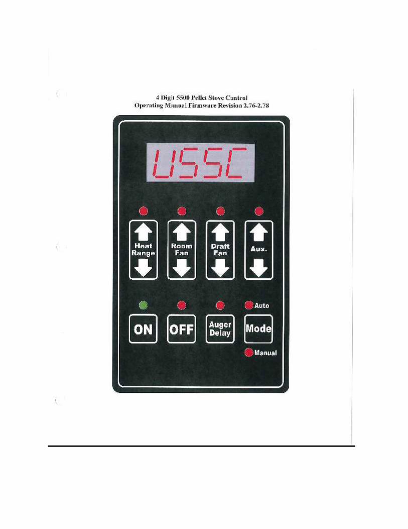
5500M, 5500XL, and5510
4 Digit Board
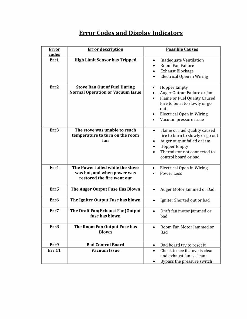
Error Codes and Display Indicators
Error codes
Error description Possible Causes
Err1 High Limit Sensor has Tripped Inadequate Ventilation Room Fan Failure Exhaust Blockage Electrical Open in Wiring
Err2 Stove Ran Out of Fuel During
Normal Operation or Vacuum Issue Hopper Empty Auger Output Failure or Jam Flame or Fuel Quality Caused
Fire to burn to slowly or go out
Electrical Open in Wiring Vacuum pressure issue
Err3 The stove was unable to reach
temperature to turn on the room fan
Flame or Fuel Quality caused fire to burn to slowly or go out
Auger output failed or jam Hopper Empty Thermistor not connected to
control board or bad
Err4 The Power failed while the stove was hot, and when power was
restored the fire went out
Electrical Open in Wiring Power Loss
Err5 The Auger Output Fuse Has Blown Auger Motor Jammed or Bad
Err6 The Igniter Output Fuse has blown Igniter Shorted out or bad
Err7 The Draft Fan(Exhaust Fan)Output fuse has blown
Draft fan motor jammed or bad
Err8 The Room Fan Output Fuse has Blown
Room Fan Motor Jammed or Bad
Err9 Bad Control Board Bad board try to reset it Err 11 Vacuum Issue Check to see if stove is clean
and exhaust fan is clean Bypass the pressure switch

Display Indicators
Several situations or events are indicated in normal operation by blinking display indicators or
segments in the display:
Flashing On Light: This means that the stove is in the “Start Up” state waiting for either a 3 minute
time-out to begin burning or for the stove to reach the warm temperature whichever comes first.
Flashing Off Light: This indicates that the stove is in the shutdown state waiting for the OFF
button, or for a 15 minute period after the stove was turned off, or for the stove to cool down, or for
the door to be closed.
Flashing Dash in Heat Range Display: This indicates that the stove is in normal run mode and is
ramping from the current heat range setting to the target heat range setting. Once the ramp is
complete the dash will stop flashing. For Ramping from heat range 1 to 5, the default time is 12
minutes (with a 90 second ramp time).
Flashing Automatic Mode Indicator: This indicates that the stove is in normal operation and is
running in the automatic mode. However either the draft fan or auxiliary setting is manually
configured.
Flashing draft fan: This indicates that the stove is in normal operation and that the vacuum sensor
detects a loss of pressure either because the door is open or because there is a negative pressure in
the room with respect to the exhaust.
Flashing Aux Indicator: This Indicates that the igniter is on during the lighting stage.
Quickly Flashing Heat Range Setting Indicator (changes twice per second): This indicates that
the stove is in normal operation and that an over-temperature condition exists causing the fuel to
stop.
Slowly Flashing Heat Range Setting Indicator (changes once per second): This indicates that
the stove is in a cut back condition in an attempt to prevent an over-temperature shutdown
Factory Defaults: To return the control to its original factory default settings, Press and hold the
AUX UP and AUX DOWN buttons together for three seconds.

Possible Causes for a vacuum issue:
Gasket around door or glass not sealing properly.
Clean-out slides on front of unit open.
Clean-out slides inside firebox not closed properly.
Unit has not been cleaned: firebox, underneath firepot, behind clean-outs on inside of unit, brass port
inside firebox clogged, vacuum hose clogged-brittle-cracked, exhaust pipe clogged, exhaust pipes not
sealed, improper venting—excessive horizontal length—too many elbows—vented INTO chimney, and
the last thing to rule out is a faulty pressure switch itself.
90 to 95% of the time a faulty pressure switch is NOT the problem.
Just because the unit will run with the pressure switch “jumped” does not mean
the pressure switch is faulty. It simply means we have told the unit to “ignore”
the vacuum problem.
Cleaning firebox: clean thoroughly, remove firepot-clean underneath, clean brass port in firebox,
remove ceramic brick (6039-6041)—tap on the back wall of the firebox several times to loosen any
accumulated soot or ash-lift clean-out slides-remove any and all soot and ash—may need to use a
flexible brush or some customers use a straightened wire clothes hanger and push any build-up in
between the two clean-outs to one side or another and then remove.
Check gasket around door and glass and make sure it seals all the way around-that it is not frayed or
burned allowing any gaps.(some 5500-5510 have gaps at bottom of glass gasket)
Make sure the door seals—doing paper test.
UNPLUG UNIT.
Remove side panel—left side facing stove—locate pressure switch-remove hose from pressure switch-
blow through to make sure it is not clogged or cracked. Make sure it is connected well to the brass port
going into the back of the firebox,--AGAIN—make sure it is not brittle cracked or damaged—reconnect
hose to pressure switch making sure the clamp is tight.
Make sure the exhaust piping has been cleaned—all of it, not just the clean-out tee removed and
emptied.
Make sure the piping is sealed—especially the first piece attached to the exhaust pipe.
THESE UNITS CANNOT BE VENTED INTO A CHIMNEY. THE PIPE-(3” or 4” PELL VENT)- MUST RUN ALL
THE WAY TO THE TOP.

5500M 4 Digit Control Board Test
To run this test the UNIT MUST BE COOLED OFF. Power up the unit by plugging in the power supply cord
to the back of the unit. Press the on button and the circuit board then press and hold the Off and Auger
Delay buttons simultaneously for 3 seconds. To advance through the test press the on key. If the Heat
Range Light is on during every test check Hopper Switch Wires.
1. Exhaust Fan Output Test- The display will show “drift”. The exhaust fan is turned on full then
reduced to a level just above the typical minimum pressure switch setting. The ON LED indicates
whether the pressure sensor is detected. If the pressure switch is not detected, the fan ramps to full
on for two seconds then returns to the previously established level if the pressure switch closes. If
the Draft Fan Fuse is not blown and the fuse detection circuit is functioning, the Draft Fan LED will
be lit and the other three top row LEDs will be off.
2. Room Fan Output Test – The display will show “rfan”. The room fan is turned on full. If the Room
Fan Fuse is not blown and the fuse detection circuit is functioning, the Room Fan LED will be lit and
the other three top row LEDs will be off.
3. Igniter Output Test – The display will show “ignt”. The igniter motor is turned on full. If the Igniter
(AUX) Fuse is not blown and the fuse detection circuit is functioning, the AUX LED will lit and the
other three top row LEDs will be off.
4. Auger Output Test – The display will show “augr”. The auger motor is turned on full. If the auger
fuse is not blown and the fuse detection circuit is functioning, the Heat Range LED will be lit and the
other three top row LEDs will be off.
5. Hopper Switch Test – The display will show “hppr”. If the hopper switch is open (lid is open), the ON
LED will turn on otherwise, it will be off. If the hopper switch is wired in series with the auger, this
test is not valid, and the validation of the hopper switch should be done in the previous Auger
Output test.
6. Thermostat Input Test – The display will show “stat”. If the thermostat input is closed, the ON LED
light will be on, otherwise it will be off.
7. Flue gas Thermistor Test – The display will show the fluegas temperature in degrees F. This should
read 54° F
8. AC Frequency Test - Displays the measured AC frequency in hertz followed by the letter “H”.
This should read 59, 60, or 61H
9. Watchdog Reset – The Watchdog timer is tested to ensure that the board can be reset. The message
“BYE” will be displayed until the Watchdog resets board.

5500M C Codes
To adjust the operation constants, press the hold the MODE and AUGER DELAY buttons simultaneously
for 3 seconds. The display will show “C-1”. Use the HEAT RANGE UP or HEAT RANGE DOWN buttons to
change the constant number (see the list of vales below). When the desired constant is displayed, press
the ON button to toggle between viewing and editing the value. While editing a parameter, use the AUX
again to return to the constant number list. Press the OFF button to exit the operational constants
mode.
C1- Reset to defaults (hold Mode and Auger Delay buttons for 3 seconds to reset all to defaults).
C2- Fuel Lbs. per Hour HR 1 (0-5.0) – This is the fuel rate in pounds per hour for a heat range
setting of 1. The default is 1.75 lbs.
C3- Fuel lbs. per Hour HR 9 (0-5.0) – This is the fuel rate in pounds per hour for a heat range
setting of 5. The default is 4.5lbs. The fuel rates used between setting 1 and 5 are linearly
interpolated between these two settings.
C4- Draft Fan Level HR 1 (0-500) – This is the draft fan output level for a draft fan setting of 9.
The default is 150
C5- Draft Fan Level HR 9 (0-500) – This is the draft fan output level for a draft fan setting of 9.
The default is 350. See next parameter for disbursement.
C6- Monitor Hopper Switch (0-1) – If this parameter is set to 0 (default), the hopper switch input
is ignored. If it is set to 1, the hopper input is monitored, and if the hopper is opened, the auger
will stop. The delay LED will flash when the hopper is opened.
C7- Ramp Seconds for increasing level (0-300) – When the heat range setting is adjusted, control
will ramp from the current setting to the target setting to avoid abrupt changes in the outputs
that could cause problems with the flame quality. The ramp seconds value sets the amount of
time to spend on each heat range setting (1-9 pseudo ranges not 1-3 user ranges) as the current
setting is ramping toward the target. If the current setting is ramping down toward a lower
target, the ramp value is half this number. The default value is 90 seconds.
C8- Startup Minutes for detecting Warm Stove – (10-60) this is the amount of time the control
will wait for the stove to reach the warm temperature (110 Degrees F) after the stove has been
started before shutting down and reporting an Error condition Err3. The default is 30minutes.
C9- Over temp Set point – (0-500) this is the temperature the flue gas can reach before an over
temp condition exists. If the measured temperature is higher than this set point, the control will
stop auguring fuel until the temperature returns to a safe operating point. The default is 445
degrees.
C10- Cutback Set point – This is the temperature that the flue gas can reach before a cutback
condition exists. If the measured temperature is higher than this set point, the control ramps
down the heat range according to the auger ramp seconds value. The default is 430 degrees.
C11- Room fan on set point – (0-300) this is the temperature that the measured flue gas must
reach before the room fan turns on. This variable also serves to indicate to the control that the
stove is warm. If the measured temperature is higher than this set point, the stove is considered
warm and will not create an Er3. Whether or not the stove is warm also determines if the unit
will recover from a power failure. If the stove is warm when the power is lost and cold when it
returns, it will shut down with an Er4 error. The default is 130 degrees.

C12- Cold stove set point – (0-300) this variable is used to determine when the stove is cold and
ready to be shut down. If during the shutdown sequence the measured temperature is less than
this value, the stove will stop running the fans to cool it off. The default is 110 degrees.
C13- Room fan level HR 9 (0-500) – this is the output level applied to the room fan for a setting o
1. The default values is 300/500.
C14- Room fan level HR 9 (0-500) – This is the output level applied to the room fan for a setting
of 9. The default value is 500/500. The room fan output levels used between settings 1 and 9 are
linearly interpolated between these two settings.
C15- Auger load time (0-30) – This variable is used to control the length of time that the fuel is
augured into the burn pot during startup. The default is 6 minutes.
C16- Starter on time (0-30) – This variable is used to control the length of time that the igniter is
turned on during startup. The default is 8 minutes.
C17- Ignore fuse errors (0-1) – This variable can be used to ignore errors detected by open fuses.
By default, it is o (do not ignore the vacuum switch), but can be set to 1 for diagnostic of
emergency operation purpose.
C18- Ignore vacuum switch (0-1) – This variable can be used to ignore the vacuum switch. By
default it 0 (do not ignore the vacuum switch), but can be set to 1 for diagnostic or emergency
operation purposes.
C19- Bump rate in pounds per hour (0-0.5) – The bump rate defines the rate of fuel to be
delivered when the unit is over temperature or in shutdown to prevent burn back, Since this
stove design isn’t conductive to burn back, the default setting is 0lbs. per hour, but can be
adjusted to a maximum of 0.5lbs per hour.
C20- Purge time (0-120) – The purge time defines how many seconds to run the auger to purge
it on power down or shutdown as the stove moves from a warm state to a cool state. It is
intended to push and partially heated pellets still in the auger tube out. By default, the auger
will run for 30 seconds, but can be set between 0 and 120.
C21- Enable serial communication (0-10 – By default, serial communication is not enabled (0).
Set this variable to 1 to enable communication.

How to check the exhaust and duct temperature in real
time:
U CODES
1) Press and hold Mode and Draft Fan UP......hold until you see U1
2) Press the On Button it will display a 3 digit number (this is the current exhaust
temperature)
3) Press OFF it will go back to U1
If a furnace
4) Press Heat Range UP to U2 and Press ON (this is the current duct temp.)
5) Press OFF will go to U2
6) Press OFF the control board will go back to the main control board