PRODUCT SELECTION GUIDE - TNB.COMtnblnx3.tnb.com/emAlbum/albums//Elastimold/Elastimold...
64
PG-PC-E-0509 PRODUCT CATEGORIES • Underground Distribution Switchgear • Molded Fuse Products • Surge Arresters UTILITY PRODUCTS/ELASTIMOLD utility.tnb.com PRODUCT SELECTION GUIDE
Transcript of PRODUCT SELECTION GUIDE - TNB.COMtnblnx3.tnb.com/emAlbum/albums//Elastimold/Elastimold...

PG-PC-E-0509
PRODUCT CATEGORIES
• Underground Distribution Switchgear
• Molded Fuse Products
• Surge Arresters
UTILITY PRODUCTS/ELASTIMOLD
utility.tnb.com
PRODUCT
SELECTION
GUIDE


product page(s)
Overview . . . . . . . . . . . . . . . . . . . . . . . . . . . . . . . . . . . . . . . . . . . . 3–13
Molded Vacuum Switches and Fault Interrupters . . . . . . . . . . . . . 14–21
Multi-Way Switchgear and Transfer Packages . . . . . . . . . . . . . . . 22–27
New Elastimold® Molded Vacuum InterrupterSwitchgear Products . . . . . . . . . . . . . . . . . . . . . . . . . . . . . . . . . . . . . 28
PG-PC-E-0509 800.326.5282 • 8155 T&B Boulevard Memphis TN 38125utility.tnb.com 1
Contents
Underground Distribution Switchgear
product page(s)
Overview . . . . . . . . . . . . . . . . . . . . . . . . . . . . . . . . . . . . . . . . . . . 29–30
Fused Elbows . . . . . . . . . . . . . . . . . . . . . . . . . . . . . . . . . . . . . . . 31–33
Molded Current-Limiting Fuses . . . . . . . . . . . . . . . . . . . . . . . . . . 34–42
Molded Canister Fuses . . . . . . . . . . . . . . . . . . . . . . . . . . . . . . . . 43–50
Molded Fuse Products
product page(s)
Overview . . . . . . . . . . . . . . . . . . . . . . . . . . . . . . . . . . . . . . . . . . . . . . 51
MOV Surge Arresters . . . . . . . . . . . . . . . . . . . . . . . . . . . . . . . . . . 52–57
Surge Arresters
TnB_Elas-08_Guide_00&01:TnB_Elas-08_Guide_00&01 6/15/09 8:13 AM Page 1

Thomas & Betts’ Elastimold® brand is the
worldwide recognized leader in premolded cable
accessory components, providing innovative
connector designs as well as vacuum switches
and interrupters, arresters and fused elbows.

Overview
PG-PC-E-0509 800.326.5282 • 8155 T&B Boulevard Memphis TN 38125utility.tnb.com 3
Reduce power interruptions withunderground distribution switchgear.
Molded Vacuum Switchesand Fault Interrupters. . . . . .14–21
Multi-Way Switchgearand Transfer Packages. . . . .22–27
New Molded Vacuum InterrupterSwitchgear Products. . . . . . . . .28
Downtime — you know it’s going to happen. But with Elastimold® Switchgear, you can help decrease theduration and frequency of outages and fluctuating line conditions. Choose from a wide variety of productsfor switching, sectionalizing, source transfer and overcurrent protection — so you can keep the power flowing.
QUICK REFERENCE
Elastimold®
UndergroundDistributionSwitchgear page(s)
Underground
Distribution
Sw
itchgear

8155 T&B Boulevard Memphis TN 38125 • 800.326.5282 PG-PC-E-0509utility.tnb.com4
Overview
EPDM Molded Rubber Construction
with Stainless Steel Hardware All switchgear components are fully sealed and submersible.
and Mechanism Boxes
Vacuum Switching and
Vacuum InterruptingSwitchgear components are maintenance-free and require no gas or oil.
Deadfront Construction Insulates, shields and eliminates exposed live parts.
Compact and Lightweight ComponentsSmall footprint enables components to fit in tight padmount, subsurface,
vault or riser pole installations.
Non-Position SensitiveCan be installed almost anywhere and in any position (e.g. hanging from ceilings,
wall mounted, mounted at an angle, riser pole mounted).
Modular ConstructionAllows for any combination of fused, switched and interrupter ways on one piece
of switchgear up to 35kV.
Electronic Controls for Protection and With self-powered controls and customized protection curves, you get flexibility
Automatic Source Transfer Applications of settings and operation in different locations throughout the distribution system.
Motor Operators for Remote/Local Open/Enable remote configuration of loops, sectionalizing of feeders and automatic
Close Operation of Three-Phase Switchedor manual source transfer with a wide variety of RTUs and communication devices.
or Interrupter Ways
Benefits/DescriptionsFeatures
Und
ergr
ound
Dis
trib
utio
nS
witc
hgea
r
Whether it is a standard or a custom
application, Thomas & Betts has the right
combination of components and expertise
to fit your needs. The modularity and flexibility
of Elastimold® Switchgear enable the user to
combine the different individual components
into products that improve the reliability
and performance of distribution systems.
• Single-Phase and Three-PhaseMolded Vacuum Switches (MVS)
• Single-Phase and Three-PhaseMolded Vacuum Interrupters (MVI)
• Current-Limiting Fuses
These components — combined with
electronic controls, motor operators and
SCADA-ready controls — make the building
blocks of Elastimold® Switchgear.
Three basic components form the basis
of Elastimold® Switchgear:
Use Switchgear Building Blocks to create standardconfigurations and custom designs that improveyour distribution system’s reliability.

Overview
PG-PC-E-0509 800.326.5282 • 8155 T&B Boulevard Memphis TN 38125utility.tnb.com 5
Elastimold® Switchgear products are classified in three
categories according to the function they perform:
• Switching and Sectionalizing Equipment• Automatic Source Transfer Equipment• Overcurrent Protection Equipment
Switchgear products can be used in padmount,
subsurface/wet or dry vaults and riser pole
installations. The switching or manual sectionalizing
of loads can be accomplished with the use of Molded
Vacuum Switch (MVS) modules. The simplest manual
sectionalizer is a single MVS switch, which can be
installed in a vault, on a pole or inside a padmount
enclosure. One of the most popular applications of
this sectionalizer is as a replacement for existing oil
fuse cutouts. Two-, three- and four-way units are also
available in vault and padmount styles. Switches also
aid in the manual reconfiguration of distribution loops
by installing them at the open point in the circuit.
Overcurrent protection is accomplished using Molded
Canister Fuse (MCAN) or Molded Vacuum Interrupter
(MVI) modules. These can be used in combination
with MVS modules. The simplest product is a single MVI unit, which can be installed in a vault, on a pole or inside a padmount enclosure. A common
application for this configuration is as a replacement for existing oil fuse cutouts. Two-, three- and four-way units are also available in any combination
of MVI, MCAN and MVS modules, and in vault and padmount styles. Fuses and interrupters are applied in underground loops to aid in the
sectionalizing of the main feeder, and by providing protection to the loads along the loop. For more information on canister fuses, see pages 43–50.
Configure Switchgear Building Blocks to solve challenges in yourdistribution system.
Riser Pole Vault
SubsurfacePadmount
Underground Distribution Switchgear Applications
CriticalLoad
AutomaticSourceTransfer
Overcurrent/Sectionalizing
Sectionalizing
Substation 3
NO
NC
NO
NCNC NC
S
Switchgear 3
Switchgear 2
Switchgear 1
Substation 1
Substation 2
S
S
NOTE: NC = normally closedNO = normally opened
Underground
Distribution
Sw
itchgear

Overview
8155 T&B Boulevard Memphis TN 38125 • 800.326.5282 PG-PC-E-0509utility.tnb.com6
• A load needs to be isolated to perform maintenance• A load needs to be isolated to repair a fault• A loop needs to be reconfigured to feed a certain load from a different substation and isolate the faulted portion of the loop
In any case, the use of a manual sectionalizer contributes to reduce the length of time that unfaulted or unaffected portions of the system are
exposed to an outage. This results in improved reliability of the system as the duration of outages is reduced (i.e. the SAIDI and CAIDI reliability
indices). Switching products can be applied as replacements for existing oil fuse cutouts or as manual sectionalizers for loops or radial feeders.
Depending on the application, these sectionalizers may be installed in a vault or inside a padmount enclosure. Pole installations are also available.
Load switching is required when:
Similar application of MVS switches in loop configurations contribute to significantly reduce the outage duration. In these cases, single- or multi-way
switch configurations can be applied.
Without Manual Sectionalizing
S1T
F1 F2
T
T
TBreaker 500 Users 500 Users
MVS
S1T
F1 F2
T
T
TBreaker 500 Users 500 Users
MVS Manual Sectionalizing Unit = Shorter restoration timefor 500 customers
Permanent Faults F1 and F2Interruption Duration: F1 = 1 hr.; F2 = 2 hr. for 500 users;
F2 = 1 hr. for 500 usersEvaluation Period = 1 yr.
SAIDI = [(1 hr.) x (1000) + (1 hr.) x (500) + (2 hr.) x (500)]/1000 = 2.5 hr./yr.SAIFI = [1000 + 1000]/1000 = 2 interruptions/yr.
With the use of an MVS at the midpoint of the feeder, the
restoration time is reduced. Once the fault is located, the MVS
is open to isolate the faulted portion of the feeder. At this point,
the other half of the feeder can be energized, reducing the outage
duration or SAIDI from 3 hours to 2.5 hours per year (16.6%).
No Manual Sectionalizing UnitPermanent Faults F1 and F2Interruption Duration: F1 = 1 hr.; F2 = 2 hr.Evaluation Period = 1 yr.
SAIDI = [(1 hr.) x (1000) + (2 hr.) x (1000)]/1000 = 3 hr./yr.SAIFI = [1000 + 1000]/1000 = 2 interruptions/yr.
In this example, a radial feeder is exposed to two failures in one
year. Without any manual sectionalizing, all customers are subject
to both failures and are out of power until failures are restored.
Assuming that the duration of outage one (F1) is 1 hour, and
outage 2 (F2) is 2 hours, the calculation of SAIDI shows 3 hours
of interruption duration per year.
With MVS Manual Sectionalizing —Improved Reliability!
Und
ergr
ound
Dis
trib
utio
nS
witc
hgea
r
TnB_Elas-08_Guide_06-07:TnB_Elas-08_Guide_06-07 6/15/09 8:17 AM Page 6
Without Manual orAutomatic Sectionalizing
Automatic Sectionalizing Switchgear
Overview
PG-PC-E-0509 800.326.5282 • 8155 T&B Boulevard Memphis TN 38125utility.tnb.com 7
Fault-interrupting devices are used on:• Feeders to sectionalize, so that if there is a fault, only a small section of the load is affected• Radial taps deriving from a main feeder or loop, so that a fault on a tap is isolated from the main circuit• Network transformers to isolate the devices in case of overcurrent, excessive pressure/temperature, etc.
While a switching device contributes to decrease the duration of outages, fault interrupters contribute to decrease the duration AND frequency
of outages (i.e. SAIDI, CAIDI, SAIFI, CAIFI reliability indices).
With MVI Automatic Sectionalizing —Improved Reliability!
ESP313-BJB-XXX
MVIInterrupters
3-PointJunctions
Similar improvements can be accomplished with the use of MVIs in loop systems. A typical example of the use of radial protection off the main feeder
to improve reliability is the use of single-phase MVIs in sectionalizing cabinets. These cabinets can be installed with no tap protection at the beginning
of a construction project, and MVIs can be added as the loads come online.
In this example, a radial feeder is exposed to two failures in one
year. Without any automatic sectionalizing (overcurrent protection),
all customers are subject to both failures and are out of power
until failures are restored. Assuming that the duration of outage
one (F1) is 1 hour, and outage two (F2) is 2 hours, the calculation
of SAIDI shows 3 hours of interruption duration per year.
The calculation of the frequency of interruptions (SAIFI)
shows two interruptions per year.
No Automatic Sectionalizing UnitPermanent Faults F1 and F2Interruption Duration: F1 = 1 hr.; F2 = 2 hr.Evaluation Period = 1 yr.
SAIDI = [(1 hr.) x (1000) + (2 hr.) x (1000)]/1000 = 3 hr./yr.SAIFI = [1000 + 1000]/1000 = 2 interruptions/yr.
MVI Automatic Sectionalizing Unit = Eliminate one interruption for 500 usersPermanent Faults F1 and F2Interruption Duration: F1 = 1 hr.; F2 = 2 hr. for 500 usersEvaluation Period = 1 yr.
SAIDI = [(1 hr.) x (1000) + (2 hr.) x (500)]/1000 = 2 hr./yr.SAIFI = [1000 + 500]/1000 = 1.5 interruptions/yr.
With the use of an MVI overcurrent fault-interrupting device at
the midpoint of the feeder, failure F2 only affects half of the load.
Proper protection coordination between the MVI and the
substation breaker enables the MVI to clear the fault before
any customers between the MVI and the breaker are affected.
Frequency and duration of interruption are significantly reduced.
SAIDI is reduced from 3 to 2 hours of interruption per year (33%),
and SAIFI is reduced from 2 to 1.5 interruptions per year (25%).
S1T
F1 F2
T
T TBreaker 500 Users 500 Users
MVI
S1T
F1 F2
T
T
TBreaker
500 Users 500 Users
Underground
Distribution
Sw
itchgear
TnB_Elas-08_Guide_06-07:TnB_Elas-08_Guide_06-07 6/15/09 8:17 AM Page 7

In the case of underground loops, the switching devices along the
loop can be used to reconfigure the loop. Thus, regardless of the
location of the fault, the switches will operate to isolate the faulted
portion of the loop and restore service to the remaining customers.
In the following example, permanent Fault A will cause the breaker
to lock out, and all customers up to the open point will be subjected
to an outage. The next step is to locate the fault. After the fault is
located, it is necessary to reconfigure the loop to isolate the faulted
portion. This is done by opening Switch 1 and closing Switch 2.
These operations can be done manually or via SCADA.
Und
erg
roun
dD
istr
ibut
ion
Sw
itch
gea
rOverview
8155 T&B Boulevard Memphis TN 38125 • 800.326.5282 PG-PC-E-0509utility.tnb.com8
Underground Loop Systems
Example: Underground Loop System
BreakerLocks Out
NCSwitch 1
B1 S2
Switch 2NO
B2 S3
Switchgear 1
Switchgear 2
S4
NC
NC
Fault A
BreakerLocks Out
B1 S2
Switch 2
CLOSE
OPENSwitch 1
B2 S3
Switchgear 1
Switchgear 2
S4
NC
NC
Fault A
NOTE: NC = normally closedNO = normally opened
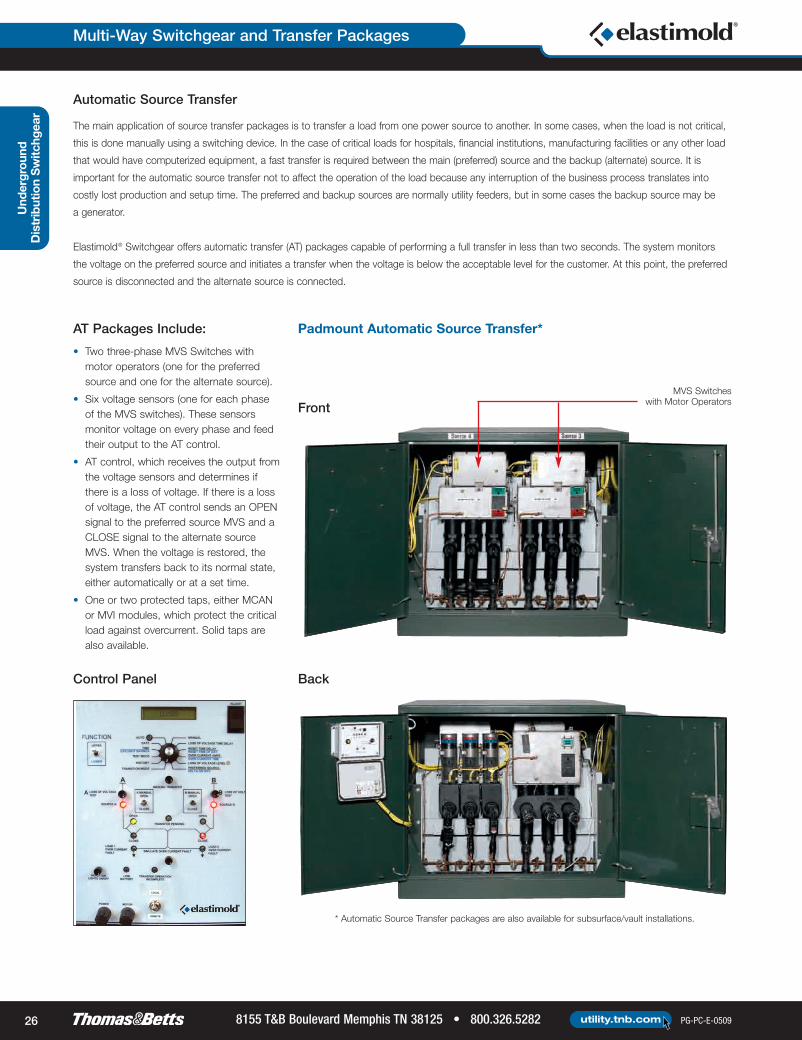
Automatic Source TransferThe main application of source transfer packages is to transfer a load from one power source to another. In some cases, when the load is not critical,
this is done manually using a switching device. In the case of critical loads for hospitals, financial institutions, manufacturing facilities or any other load
that would have computerized equipment, a fast transfer is required between the main (preferred) source and the backup (alternate) source. It is
important for the automatic source transfer not to affect the operation of the load because any interruption of the business process translates into
costly lost production and setup time. The preferred and backup sources are normally utility feeders, but in some cases the backup source may be
a generator.
Elastimold® Switchgear offers automatic transfer (AT) packages capable of performing a full transfer in less than two seconds. The system monitors
the voltage on the preferred source and initiates a transfer when the voltage is below the acceptable level for the customer. At this point, the preferred
source is disconnected and the alternate source is connected.

Overview
PG-PC-E-0509 800.326.5282 • 8155 T&B Boulevard Memphis TN 38125utility.tnb.com 9
AT Packages Include: Padmount Automatic Source Transfer*
• Two three-phase MVS Switches withmotor operators (one for the preferredsource and one for the alternate source).
• Six voltage sensors (one for each phaseof the MVS switches). These sensorsmonitor voltage on every phase and feedtheir output to the AT control.
• AT control, which receives the output fromthe voltage sensors and determines ifthere is a loss of voltage. If there is a lossof voltage, the AT control sends an OPENsignal to the preferred source MVS and aCLOSE signal to the alternate sourceMVS. When the voltage is restored, thesystem transfers back to its normal state,either automatically or at a set time.
• One or two protected taps, either MCANor MVI modules, which protect the criticalload against overcurrent. Solid taps arealso available.
* Automatic Source Transfer packages are also available for subsurface/vault installations.
MVS Switcheswith Motor Operators
VoltageSensor
Back
FrontControl Panel
Underground
Distribution
Sw
itchgear

Und
ergr
ound
Dis
trib
utio
nS
witc
hgea
rOverview
8155 T&B Boulevard Memphis TN 38125 • 800.326.5282 PG-PC-E-0509utility.tnb.com10
Motor Control Motor Operated Switch
Distribution Automation
Elastimold® Modular Switchgear offers the ability to add automation to existing or new
installations. DC or AC motor operators can be added to switches or interrupters in vault,
riser pole or padmount installations. The motors are submersible, and the same automation
package can be used in all applications. The motors can either be operated from a short
distance using a handheld device, as is the case with some vault installations, or they
can be outfitted with fully automated controls containing:
• Early detection and correction of abnormal line conditions• Reduced frequency and duration of outages• Remote control and automatic restoration• Improved dispatcher decision making and field manpower savings• Automation packages can be added or upgraded as the system requirements change
NOTE: Consult your local representative on specific distribution automation packages and configurations available.
Riser PoleInstallation
Elastimold® distribution automation products are designed for interoperability and rapid automation implementation. These products can provide
a supervisory control and data acquisition (SCADA) system interface and enable feeder automation with or without communications. Elastimold
distribution automation products will help to strengthen existing distribution systems and provide a strong foundation for building a fully
implemented scheme in the future. Here are some of the benefits of distribution automation implementation:
Automated Units
• Battery• Power supply• Customer-selected RTU• Customer-selected communications protocol• Customer-selected communications device
Overview
PG-PC-E-0509 800.326.5282 • 8155 T&B Boulevard Memphis TN 38125utility.tnb.com 11
Underground
Distribution
Sw
itchgear
The loss of redundancy indices are calculated in the following example.
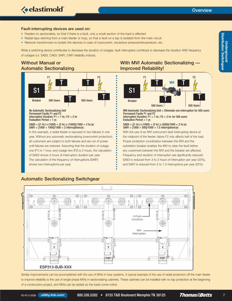
The reliability of conventional radial or looped underground distribution circuits is measured in
terms of the number and/or frequency of interruptions. These measurements cannot be directly
applied to a network system. A typical network system has built-in redundancy. During most
events, the continuity of power supplied to the end user is not affected by fault conditions on
the high side of the network transformers. So, from the point of view of customer interruptions,
network systems are reliable.
However, transformer failures have been known to result in catastrophic fires, explosions and even
loss of lives. The failure or overload of multiple transformers within a network may ultimately result
in the interruption of service to the end user.
Network Transformer Protection
• Transformer fire• Transformer overheating• Transformer pressure build-up• Overcurrent condition
Loss of redundancy can occur
as a consequence of:
While the substation breaker may detect most overcurrent faults, faults caused by excessive pressure/heat or fires cannot be detected by the breaker.
One method that automatically isolates a network transformer from the primary side, regardless of the type of failure, is the installation of an MVI fault
interrupter on the high side of the transformer. This MVI can isolate based on overcurrent conditions, but also can be wired to isolate the transformer
in case of fire, excessive pressure/heat, emergency signal, etc.
• Minimization of fire damage
• Reduction or elimination of transformer damage due to pressure or temperature build-up
• Longer transformer life
Benefits of such a setup to the network system and the end users include:
Loss of redundancy is a method that highlights the increased vulnerability of the system
every time a network transformer is lost. Loss of redundancy indices are calculated as follows:
Duration of Loss of Redundancy (hours/year) =
Frequency of Loss of Redundancy (times/year) =
The number of transformers in the circuit is the number of transformers energized
by the same feeder.
S (No. Hours a Transformer is Disconnectedx No. of Transformers in the Circuit)
No. of Transformers in the Circuit
Total No. of Transformer De-Energizations
No. of Transformers in the Circuit
Loss of Redundancy
Example 1: No High-Side Transformer Protection
Consider one substation breaker and one exclusive feeder out to the network. Five transformers
are energized by the same feeder. Assume one permanent fault on one transformer in one year.
Also assume the faulted transformer is de-energized for six hours:
Because there is only one breaker for five transformers, a failure in one transformer
translates to the interruption of power to five transformers for six hours.
Frequency of Loss of Redundancy (times/year) =
Duration of Loss of Redundancy (hours/year) = = 6 hours/year
= 1 time/year
(6 x 5)5
55

Overview
8155 T&B Boulevard Memphis TN 38125 • 800.326.5282 PG-PC-E-0509utility.tnb.com12
The following example calculates the loss of redundancy to the same system used in Example 1,
but adding protection to the primary side of the transformers.
Once an MVI is installed, remote operation from the entrance of the vault or via SCADA is possible
with the addition of a motor operator and control. Installation of panic/emergency push buttons at
the entrance of the vault is also possible; pressing this emergency switch will instantaneously
trip open one or all of the interrupters in a vault and isolate the transformers.
Example 2: High-Side Transformer Protection
There is one substation breaker and one exclusive feeder out to the network. Five
transformers are energized by the same feeder. Each transformer is equipped with a fault
interrupter installed on the high side. Assume one permanent fault on one transformer in one
year. Assume the transformer is de-energized for six hours:
A failure in one transformer translates to the interruption of power to only one transformer
for six hours.
Frequency of Loss of Redundancy (times/year) =
Duration of Loss of Redundancy (hours/year) = = 1.2 hour/year
= 0.2 time/year
(6 x 1)5
15
Local/RemoteOperation
SecondaryRelayOutputs
EPDMMoldedVacuum
Interrupters
Local/RemoteOperation
NetworkService Bus
Trip
NetworkProtector
Transformers
NetworkProtectorFuse
Trip
NetworkProtector
NetworkProtectorFuse
SecondaryRelayOutputs
Transformer Network with Protectionon the High Side of the Transformer
MVI MVI
Und
erground
DistributionSwitchgear

Underground
Distribution
Switchgear
Overview
PG-PC-E-0509 800.326.5282 • 8155 T&B Boulevard Memphis TN 38125utility.tnb.com 13
Elastimold® Switchgear Network Package (NMVI3)
51⁄2"(140mm)
120VACPowerSupply
GroundLug
Programmable Control& Current Transformer
Mounting Bolts,1⁄2" (13mm)
ContactPositionIndicator
MVI Motor
51⁄2"(140mm)
181⁄2"(470mm)Mounting
429⁄64"(1,070mm)
61⁄4"(159mm)
14"(356mm)Mounting
19"(483mm)Mounting
Network Control
DOOR IN OPEN POSITION
Product Selection
Elastimold Part OrderingFunction Application Installation Products Number Page(s)
Switching Oil Fuse Cutout Replacement Subsurface/Vault Molded Vacuum Switches MVS 20
Sectionalizing Manual Underground Feeder Subsurface/Vault Switching and Sectionalizing ESV24
pages 6–8 or Loop Sectionalizing Padmount Switchgear PMVS, ESD
Source SubsurfaceAutomatic Source
ATS
Transfer Automatic Source Transfer Vault ATV 27pages 8–10 Padmount
Transfer PackagesATD
Riser Pole Pole RMVI
Network Transformer Protection Network Transformer Vault Molded Vacuum InterruptersMVI
21Overcurrent Oil Fuse Cutout Replacement Subsurface/VaultProtection
Automatic Underground Feeder Subsurface/Vault Overcurrent Protection ESVpages 11–12or Loop Sectionalizing 25
Underground Feeder or Loop Protection PadmountSwitchgear
PMVI/ESD

Und
ergr
ound
DistributionSwitc
hgea
rMolded Vacuum Switches and Fault Interrupters
8155 T&B Boulevard Memphis TN 38125 • 800.326.5282 PG-PC-E-0509utility.tnb.com14
Available with 600A one-piece bushings or 200A wells on either/both terminals.
41⁄16"(103mm)
Open
(4) Mounting Holes, 5⁄8" Dia. x 7⁄8" (16 x 22mm) (4) Mounting Holes, 5⁄8" Dia. x 7⁄8" (16 x 22mm)
Closed
Single-Phase SwitchesApproximate Weight: 30 lbs.
EPDM Molded Rubber Insulation MVSs are fully sealed and submersible.
Vacuum Switching and Vacuum Interruption Components are maintenance-free and require no gas or oil.
Compact and LightweightSmall footprint enables MVSs to fit in tight padmount, subsurface,
vault or riser pole installations.
Benefits/DescriptionsFeatures
121⁄2"(318mm)
67⁄16"(164mm)
51⁄2"(140mm)
137⁄16"(341mm)
2325⁄32"(604mm)
815⁄16"(227mm)
85⁄32"(207mm)
615⁄64"(176mm)
121⁄2"(318mm)
51⁄2"(140mm)
61⁄16" (154mm)
135⁄64" (39mm)
Open Closed
137⁄16"(341mm)
105⁄32"(258mm)
2527⁄32"(656mm)
615⁄64"(176mm)
43° 43°
81⁄32"(204mm)
651⁄64"(173mm)
MVS Molded Vacuum Switches include molded-in elbow connection interfaces
and spring-energy mechanisms. Available in both single- and three-phase
models, units are manually operated with a hotstick. Motor operator,
SCADA and auto-transfer control options are available.
MVS Molded Vacuum SwitchesSpring-energy, load-switching devicesthat make, carry and interrupt loadcurrents through 600A on5 to 38kV distribution systems.
TnB_Elas-08_Guide_14-15:TnB_Elas-08_Guide_14-15 6/15/09 8:20 AM Page 14

Underground
Distribution
Switchgear
Molded Vacuum Switches and Fault Interrupters
PG-PC-E-0509 800.326.5282 • 8155 T&B Boulevard Memphis TN 38125utility.tnb.com 15
Molded EPDM RubberInsulation and Shielding
OpenPosition
ClosedPosition
Vacuum InterrupterContact System
Cable ConnectionBushings
OperatingHandle
Insulated DriveRod Assembly
Spring Operating Mechanism Containedwithin 304 Stainless Steel Housing
Three-Phase SwitchesApproximate Weight: 135 lbs.
181⁄2"(483mm)
26"(660mm)
14"(356mm)
21"(533mm)
18"(470mm)
19"(483mm)
91⁄2"(241mm)
Ratings
Application Information
Maximum Design Voltage (kV) 15.5 27 38Frequency (Hz) 50/60 50/60 50/60BIL Impulse (kV) 95 125 150One-Minute AC Withstand (kV) 35 60 70Fifteen-Minute DC Withstand (kV) 53 78 103Load Interrupting & Loop Switching (Amp) 600 600 600Transformer Magnetizing Interrupting (Amp) 21 21 21Capacitor or Cable Charging Interrupting (Amp) 40 40 40Asymmetrical Momentary and 3-Operation Fault Close (Amp) 20,000 20,000 20,000Symmetrical One-Second Rating (Amp) 12,500 12,500 12,500Continuous Current (Amp) 600 600 600Eight-Hour Overload Current (Amp) 900 900 900
Construction: Submersible, corrosion resistant, fully shieldedAmbient Temperature Range: -40° C to 65° C
Patented Silicone RubberDiaphragm Separates
Line and Ground Potential
51⁄2"(140mm)
43º
Certified Tests
MVS loadbreak switches have been
designed and tested per applicable
portions of IEEE, ANSI, NEMA and other
industry standards, including:
IEEE C37.74 Standard forSubsurface, Vault and PadmountedLoad-Interrupting SwitchesIEEE 386 Standard for SeparableConnectors and Bushing InterfacesIEC 265 International Standardsfor Load-Interrupting SwitchesANSI C57.12.28 Standard forPadmount Enclosures
Available with 600A one-piece bushings or 200A wells on either/both terminals.
51⁄2"(140mm)
TnB_Elas-08_Guide_14-15:TnB_Elas-08_Guide_14-15 6/15/09 8:20 AM Page 15

Combines Vacuum Interrupters,
Programmable, Electronic, Self-PoweredComponents provide compact, lightweight
Controls and EPDM Rubber Insulationand submersible overcurrent protection.
Field Programmable with a Wide Range TCC curves provide predictable tripping
of Time-Current Characteristic (TCC) Curves for ease of coordination with upstream
and Trip Settings and/or downstream protective devices.
When the programmed parameters
Control Monitors the Circuit Condition are exceeded, a signal is sent
to the tripping mechanism.
Motor Operators and Controls AvailableEnable radial feeders or loops to be
reconfigured, either manually or via SCADA.
Benefits/DescriptionsFeatures
Und
ergr
ound
Dis
trib
utio
nS
witc
hgea
rMolded Vacuum Switches and Fault Interrupters
8155 T&B Boulevard Memphis TN 38125 • 800.326.5282 PG-PC-E-0509utility.tnb.com16
MVI Molded Vacuum Fault Interrupters include molded-in elbow connection interfaces and trip-
free mechanisms. They are available in single- and three-phase models. Units are self-powered
and include current-sensing and electronic control.
MVI Molded Vacuum Fault InterruptersMake, carry and automatically interrupt currentsthrough 25,000A symmetrical on 5 to 38kVdistribution systems.
200A Wells
600A Bushings
Front View Single-Phase
600A T Elbow Interface
Conforms toANSI Std. 386
61⁄4"(156mm)
GroundLug
Programmable Control& Current Transformer
Open/Reset
Closed/Tripped
600ABushingInterfaces
91⁄2"(241mm)
257⁄64"(73mm)
Well InterfaceAccepts StandardBushing Inserts
51⁄2"(140mm)
305⁄8"(778mm)
291⁄8"(740mm)
121⁄2"(318mm)
861⁄64"(227 mm)
527⁄32" (148mm)
861⁄64"(227mm)
815⁄16"(227mm)
Front View Three-Phase
19"(483mm)Mounting
327⁄8"(156mm)
181⁄2" (470mm)Mounting
143⁄32"(358mm)Mounting
1745⁄64"(277mm)
1057⁄64"(277mm)
51⁄2" (140mm)
LockingFeatures
Alternate Handle Position;Handle may be Repositioned in 60° Increments
51⁄2" (140mm)
600 SeriesElbow Interfaces
TnB_Elas-08_Guide_16-17:TnB_Elas-08_Guide_16-17 6/15/09 8:22 AM Page 16

Underground
Distribution
Sw
itchgearMolded Vacuum Switches and Fault Interrupters
PG-PC-E-0509 800.326.5282 • 8155 T&B Boulevard Memphis TN 38125utility.tnb.com 17
PositiveContactPosition
Operating Handle
Control Module (1-Phase)Sensing Module (3-Phase)
Cable Connection Bushings
Spring OperatingMechanismwith Tripping
Insulated DriveRod Assembly
Molded EPDM RubberInsulation and Shielding
Vacuum FaultInterrupter
Contact System
Patented Silicone Rubber DiaphragmSeparates Line and Ground Potential
Voltage Class (kV) 15.5 15.5 15.5 27 35 35Maximum Design Voltage (kV) 17 17 15.5 29 38 38Frequency (Hz) 50/60 50/60 50/60 50/60 50/60 50/60BIL Impulse Withstand (kV) 95 95 95 125 150 150One-Minute AC Withstand (kV) 35 35 35 60 70 70Five-Minute DC Withstand (kV) 53 53 53 78 103 103Continuous Current (Amp) 600 600 600 600 600 600Load Interrupting & Loop Switching (Amp) 600 600 600 600 600 600Transformer Magnetizing Interrupting (Amp) 21 21 21 21 21 21Capacitor or Cable Charging Interrupting (Amp) 40 40 40 40 40 40Symmetrical/Asymmetrical Interrupting Capability (kA) 12.5/20 16/25.6 20/32 12.5/20 12.5/20 25/40Current Sensor Ratio 1,000:1 1,000:1 1,000:1 1,000:1 1,000:1 1,000:1
Meets ANSI C37.60 requirementsAmbient Temperature Range: -40° C to 65° C
Application Information
Ratings
Certified Tests
MVI Molded Vacuum Fault Interrupters have been designed and tested per applicable
portions of IEEE, ANSI, NEMA and other industry standards, including:
ANSI C37.60 Standard for Fault InterruptersIEEE 386 Standard for Separable Connectors and Bushing InterfacesANSI C57.12.28 Standard for Padmounted Enclosures
TnB_Elas-08_Guide_16-17:TnB_Elas-08_Guide_16-17 6/15/09 8:22 AM Page 17

Include Self-Powered Electronic No batteries or external power are required. Controls send a signal to the vacuum
Control Packages interrupters to trip open and interrupt the fault when an overcurrent condition is detected.
Field-Selectable Fuse or Relay CurvesOne device for many protection schemes.
and Trip Settings
Benefits/DescriptionsFeatures
MVI Molded Vacuum Interrupter Controls
Molded Vacuum Switches and Fault Interrupters
8155 T&B Boulevard Memphis TN 38125 • 800.326.5282 PG-PC-E-0509utility.tnb.com18
Internal Control
This control is integral to the unit (no separate control box). It is accessible via a computer
connection to view or modify settings. This control is used on ganged three-phase or single-phase
MVI interrupters. Phase and ground trip, as well as inrush restraint, are available. The E-Set
software enables the user to connect to the internal control, either in the shop or in the field, to
program or change settings. An MVI-STP-USB programming connector is required to connect
between the PC and the MVI. With a computer connected to the MVI control, the user can view
real-time currents, the number of overcurrent protection operations, current magnitude of the last
trip and the phase/ground fault targets. This is the standard control option.
External Control with Single-/Three-Phase Trip Selection(Style 10 and 310)
This control is mounted externally to the mechanism and provides the ability to select TCCs by
setting DIP switches on the front panel. Each phase can be assigned a different minimum trip
setting by means of manual rotary switches. This control is used on one, two or three single-phase
MVI mechanisms.
External Control with Phase and Ground Trip (Style 20 and 320)
This control is mounted externally to the mechanism and provides the ability to select phase
minimum trip (one for all three phases), time delay for phase tripping, ground trip as a percent
of phase minimum trip and ground trip delay by means of manual rotary switches. This control
may be used on ganged three-phase or three single-phase MVI mechanisms.
NOTE: E-Set can be downloaded from www.elastimoldswitchgear.com.
Choose from five electronic control options to interrupt faults.Molded Vacuum Interrupters are provided with self-powered electronic control packages requiring no batteries or external power.
Depending on the application, five electronic control options are available for the MVI — see below and on following page.
Und
ergr
ound
Dis
trib
utio
nS
witc
hgea
r

Molded Vacuum Switches and Fault Interrupters
PG-PC-E-0509 800.326.5282 • 8155 T&B Boulevard Memphis TN 38125utility.tnb.com 19
Underground
Distribution
Sw
itchgear
54 MVI-TCC-54 E Slow55 MVI-TCC-55 E Standard56 MVI-TCC-56 Oil Fuse Cutout57 MVI-TCC-57 K58 MVI-TCC-58 Kearney QA59 MVI-TCC-59 Cooper NX-C60 MVI-TCC-60 T
External Control with Three-Phase Trip Only (Style 30 and 330)
This control is mounted externally to the mechanism and provides the ability to select phase
minimum trip (one for all three phases) by means of a manual rotary switch. It also has an RS-232
port for connection to a PC to view the last trip data. This control is used on ganged three-phase
or three single-phase MVI mechanisms.
External Control with Selectable Single-/Three-PhaseTrip Function (80 and 380 Control)
This control is mounted externally to the mechanism of the interrupter and provides the ability
to select between a single-phase trip and a three-phase trip. The 80 and 380 Control can be
used with one three-phase interrupter or with three single-phase interrupters. For three-phase
applications, the ground trip function can be blocked from the front panel. Manual trip and reset
target buttons are also located on the front panel. This control uses the E-Set software, which
enables programming via a computer using the MVI-STP-USB adapter. E-Set features custom
TCC curves and provides access to the last fault event information, as well as real-time current
per phase.
01 MVI-TCC-01 E Slow02 MVI-TCC-02 E Standard03 MVI-TCC-03 Oil Fuse Cutout04 MVI-TCC-04 K05 MVI-TCC-05 Kearney QA06 MVI-TCC-06 Cooper EF07 MVI-TCC-07 Cooper NX-C08 MVI-TCC-08 CO-11-109 MVI-TCC-09 CO-11-210 MVI-TCC-10 T11 MVI-TCC-11 CO-9-112 MVI-TCC-12 CO-9-213 MVI-TCC-13 Cooper 280ARX14 MVI-TCC-14 F16 MVI-TCC-16 Kearney KS17 MVI-TCC-17 GE Relay18–23 MVI-TCC-18–23 CO-8-1–CO-8-624–27 MVI-TCC-24–27 CO-9-3–CO-9-628–31 MVI-TCC-28–31 CO-11-3–CO-11-6
Curves
Relay Curves (minimum trip 30–600A)
Curve No. Curve Reference No. Curve Type
Fuse Curves (minimum trip 10–200A)

20 External 20 Control with Phase and Ground Trip (to be used on ganged three-phase MVI mechanism)30 External 30 Control with Three-Phase Trip Only (to be used on ganged three-phase MVI mechanism)80 External 80 Control with Selectable Single-/Three-Phase Trip Function (to be used on ganged three-phase MVI mechanism)110 External 10 Control with Single Trip Selection (to be used on one single-phase MVI mechanism)310 External 10 Control with Single-/Three-Phase Trip Selection (to be used on three single-phase MVI mechanisms)320 External 20 Control with Phase and Ground Trip (to be used on three single-phase MVI mechanisms)330 External 30 Control with Three-Phase Trip Only (to be used on three single-phase MVI mechanisms)380 External 80 Control with Selectable Single-/Three-Phase Trip Function (to be used on three single-phase mechanisms)MO120A 120VAC Motor Operator and Controller for MVS3 or MVI3 UnitsMO12D 12–24VDC Motor Operator and Controller for MVS3 or MVI3 UnitsPS Parking Stand for MVS or MVI (between bushings for single- or three-phase units)MPS Parking Stand for MVS3, MVI3 or RMVI3 on Mechanism CoverPS6 Double Parking Stand for MVS3, MVI3 or RMVI3 (between bushings and on mechanism cover)BT Bail Tab Plate Installed for Three-Phase Units OnlyP Customer Settings to Be Programmed at the Factory
Und
ergrou
ndDistributionSwitc
hgea
rMolded Vacuum Switches and Fault Interrupters
8155 T&B Boulevard Memphis TN 38125 • 800.326.5282 PG-PC-E-0509utility.tnb.com20
The following diagram shows how to construct a catalog number for
Molded Vacuum Switches and Interrupters. Catalog numbers are shown
below and on the following page.
EXAMPLE: The catalog number for a Molded Vacuum Interrupter on a
three-phase, 27kV system, with 600A terminal and parking stands
between bushings is MVI3-21-27-66-PS.
X M V X X - 2 1 - X X - X X X - S U F F I X
for Elastimold® Molded Vacuum Switches and InterruptersOrdering Information
Switch TypeR Riser PoleN NetworkBlank Subsurface
DeviceS SwitchI Interrupter
Phases1 Single-Phase3 Three-Phase
Voltage Class15 15.0kV27 27.0kV38 38.0kV
Main Interface2 200A Bushing Well6 600A Bushing
End Interface2 200A Bushing Well6 600A Bushing
InterfaceE 600A T BodyR End Interface Rotated 180˚AB Air Bushings (for Riser Pole)
NOTE: Leave suffix blank for internal (self-contained) control.
Controls and Accessories
Indicates field that must be filled in to complete order.
CAT. NO. SUFFIX Description
for Elastimold® MVS Molded Vacuum SwitchesOrdering Information
CAT. NO. Description Width in. (mm) Height in. (mm) Depth in. (mm) Weight lb. (kg) DiagramSingle-Phase Vacuum Switches
MVS1-21-15-XX 15kV 2-Way 1-Phase Switch 6 (152) 24 (610) 14 (356) 30 (14)
MVS1-21-15-6EX 15kV 2-Way 1-Phase Switch — 6 (152) 24 (610) 15 (381) 30 (14)Elbow Interface
MVS1-21-27-XX 25kV 2-Way 1-Phase Switch 6 (152) 24 (610) 14 (356) 30 (14)
MVS1-21-27-6EX 25kV 2-Way 1-Phase Switch — 6 (152) 24 (610) 15 (381) 30 (14)Elbow Interface
MVS1-21-38-XX 35kV 2-Way 1-Phase Switch 6 (152) 24 (610) 14 (356) 30 (14)Three-Phase Vacuum Switches
MVS3-21-15-XX 15kV 2-Way 3-Phase Switch 21 (533) 26 (660) 19 (483) 135 (61)MVS3-21-27-XX 25kV 2-Way 3-Phase Switch 21 (533) 26 (660) 19 (483) 135 (61)MVS3-21-38-XX 38kV 2-Way 3-Phase Switch 21 (533) 26 (660) 19 (483) 135 (61)
***
* Height includes handle. ** 3-Phase Vacuum Switches are motor-ready.
*
Cap
acitorContro
lsUnderground
Distribution
Switchgear
Molded Vacuum Switches and Fault Interrupters
PG-PC-E-0509 800.326.5282 • 8155 T&B Boulevard Memphis TN 38125utility.tnb.com 21
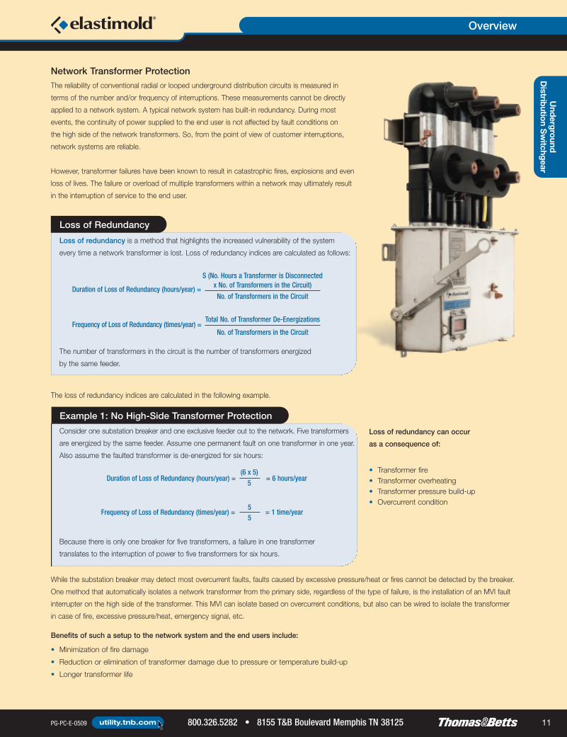
NOTE: Weights and dimensions are approximate.X = 6 for 600A or 2 for 200A or 6E for 600A T interface.Y = 10, 20, 30, 80 for different electronic controls.Leave blank for internal (self-contained) control.
Accessories should be added as suffix to the main catalog number unlessotherwise noted.Other configurations are available. Please consult your local representative onconfigurations not shown here.The 3-Phase Vacuum Interrupters are motor-ready.
CAT. NO. Description
for Accessories (order separately)Ordering Information
MVI-STP-USB Adapter for Connection between MVI Units with Internal Control and a Computer for Programming/Viewing SettingsMV1PMB Pole-Mounting Bracket for 1-Phase Units OnlyMV3PMB Pole-Mounting Bracket for 3-Phase Units OnlyMV3HPMB Horizontal Pole-Mounting Bracket for 3-Phase Units OnlyMV13PMB Pole-Mounting Bracket for Three 1-Phase Units Only35AL-11 Connector Bare Wire Type 3⁄4"–16 Rod for Riser Pole Units; Qty. of 1 Needed per Phase35AL-12 Connector 2-Hole Spade Type 3⁄4"–16 Rod for Riser Pole Units; Qty. of 1 Needed per PhaseMVI-TESTER Tester for Electric Control Style 80
CAT. NO. Description Width in. (mm) Height in. (mm) Depth in. (mm) Weight lb. (kg) DiagramRiser Pole (Three-Phase Installations Only)
RMVI3-21-15-6ABX-YY 15kV 2-Way 3-Phase Interrupter 30 (762) 45 (1,143) 25 (635) 150 (68)with Air Bushings on Top Terminals
RMVI3-21-27-6ABX-YY 25kV 2-Way 3-Phase Interrupter 30 (762) 45 (1,143) 25 (635) 150 (68)with Air Bushings on Top Terminals
RMVI3-21-38-6ABX-YY 38kV 2-Way 3-Phase Interrupter 30 (762) 45 (1,143) 25 (635) 150 (68)with Air Bushings on Top Terminals15kV 2-Way 3-Phase Interrupter
RMVI1-21-15-6ABX-3YY with Air Bushings on Top Terminals, 30 (762) 45 (1,143) 25 (635) 150 (68)1-Phase Trip Selectable
27kV 2-Way 3-Phase InterrupterRMVI1-21-27-6ABX-3YY with Air Bushings on Top Terminals, 30 (762) 45 (1,143) 25 (635) 150 (68)
1-Phase Trip Selectable38kV 2-Way 3-Phase Interrupter
RMVI1-21-38-6ABX-3YY with Air Bushings on Top Terminals, 30 (762) 45 (1,143) 25 (635) 150 (68)1-Phase Trip Selectable
Subsurface Single-Phase Vacuum Switches
MVI1-21-15-XX 15kV 2-Way 1-Phase Interrupter 6 (152) 31 (787) 9 (229) 45 (20)
MVI1-21-15-6EX 15kV 2-Way 1-Phase Interrupter, 6 (152) 31 (787) 11 (279) 45 (20)Elbow Interface
MVI1-21-27-XX 27kV 2-Way 1-Phase Interrupter 6 (152) 31 (787) 9 (229) 45 (20)
MVI1-21-27-6EX 27kV 2-Way 1-Phase Interrupter, 6 (152) 31 (787) 11 (279) 45 (20)Elbow Interface
MVI1-21-38-XX 38kV 2-Way 1-Phase Interrupter 6 (152) 31 (787) 9 (229) 45 (20)
MVI1-21-38-6EX38kV 2-Way 1-Phase Interrupter,
6 (152) 31 (787) 11 (279) 45 (20)Elbow InterfaceSubsurface Three-Phase Vacuum Switches
MVI1-21-15-XX-3YY 15kV 2-Way 3-Phase Interrupter, 20 (508) 31 (787) 9 (229) 145 (66)1-Phase Trip Selectable Ext. Control
MVI1-21-27-XX-3YY 27kV 2-Way 3-Phase Interrupter, 20 (508) 31 (787) 9 (229) 145 (66)1-Phase Trip Selectable Ext. Control
MVI1-21-38-XX-3YY 38kV 2-Way 3-Phase Interrupter, 20 (508) 31 (787) 9 (229) 145 (66)1-Phase Trip Selectable Ext. Control
MVI3-21-15-XX-YY 15kV 2-Way 3-Phase Interrupter 20 (508) 33 (838) 10 (254) 145 (66)MVI3-21-27-XX-YY 27kV 2-Way 3-Phase Interrupter 20 (508) 33 (838) 10 (254) 145 (66)MVI3-21-38-XX-YY 38kV 2-Way 3-Phase Interrupter 20 (508) 33 (838) 10 (254) 145 (66)
for Elastimold® MVI Molded Vacuum Interrupters***Ordering Information
***Air bushings on top terminal.

Multi-way vault and padmount units are built using MVS, MVI and MCAN modules
as required by the application. These are mounted onto the ES multi-way common
bus system and assembled on a free-standing, floor-mounted frame. At this stage,
the product is ready to be used in vault installations.
For padmount installations, a double-sided, drop-over, painted, mild steel enclosure
is provided. Munsell Green 7GY 3.29/1.5 is the standard enclosure color.
Other colors are available upon request. Painted stainless steel or fiberglass
enclosures are available as options.
Und
ergr
ound
Dis
trib
utio
nS
witc
hgea
rMulti-Way Switchgear and Transfer Packages
8155 T&B Boulevard Memphis TN 38125 • 800.326.5282 PG-PC-E-0509utility.tnb.com22
Multi-Way Unit Construction
Vault-Style UnitCommon Bus Assembly
Top Lifts Up for Easeof Operation
Internal ElectronicControland Current-Sensing Device(3-Phase MVIand ExternalControls alsoavailable)
200A Wells (shown);600A Bushings available
MVI Mechanism on1-Phase ProtectionTap (3-Phasealso available)
Ground Rod
Parking Stand
Padmount Unit: Tap (Load) Side
* Also available with a fiberglass enclosure.
Mild or Stainless SteelEnclosures available*
Internal ElectronicControland Current-Sensing Device(3-Phase MVIand ExternalControls alsoavailable)
TnB_Elas-08_Guide_22-23:TnB_Elas-08_Guide_22-23 6/15/09 8:27 AM Page 22

Underground
Distribution
Sw
itchgearMulti-Way Switchgear and Transfer Packages
PG-PC-E-0509 800.326.5282 • 8155 T&B Boulevard Memphis TN 38125utility.tnb.com 23
X X X X X X - X X X X - X X X X X X
The following diagram shows how to construct a catalog number
for Multi-Way Switchgear or Transfer Packages. Catalog numbers
are shown on pages 24–25 and 27 for the most common configurations.
EXAMPLE: The catalog number for an auto-transfer package for
padmount installation on a 3-phase, 27kV system, with two MVI
protected taps, 600A terminals and standard mild steel enclosure
is ATD324-AAPP-6666.
for Elastimold® Multi-Way Switchgear or Transfer PackageOrdering Information
Number of Ways2 2-Way3 3-Way4 4-Way
Voltage Class1 15.0kV2 27.0kV3 38.0kV
Phases1 1-Phase3 3-Phase
TypeV VaultS SubsurfaceD Double-Side PadmountP Single-Side Padmount
Enclosure MaterialBlank Mild SteelS Stainless Steel
Interface by Way2 200A Bushing Well6 600A Bushing
Switch TypeAT Auto TransferES Multi-Way Switch
Cabinet DepthPadmount
Blank 54"
Example: ATD324-AAPP-6666
Indicates field that must be filled in to complete order.
Components by WayA 3-Phase Switch Motor Operator
Auto TransferB Solid Tap/Direct Bus Connection
(600A or 200A)C 3-Phase MVI Fault Interrupter, 20 ControlD 3-Phase MVI Fault Interrupter, 30 ControlJ 1-Phase Fault InterrupterK 1-Phase Fault Interrupter, 10 ControlL 1-Phase Fault Interrupter, 80 ControlM 1-Phase Fault Interrupter, 20 ControlN 1-Phase Fault Interrupter, 30 ControlO 3-Phase MVI Fault Interrupter, 80 ControlP 3-Phase MVI Fault InterrupterQ 3-Phase MVS Switch with UAD ControlR 3-Phase MVI Fault Interrupter Motor Operator,
12–24VDCS 1-Phase MVS SwitchT 3-Phase MVS SwitchU 3-Phase MVS with 12–24VDC MotorV 3-Phase MVS with 120VAC MotorW 3-Phase MVI Fault Interrupter Motor Operator,
120VACZ 3-Phase MVI Fault Interrupter
with UAD Control
Custom padmount enclosure dimensions are available.
Parking stands are standard on padmount units.
Consult your local representative on multi-way configurations that include 38kV MVIs.
3-Phase MVS and MVI are motor-ready.
Auto-transfer ways 1 and 2 are always “A.”
Way 1 Way 2
A
P
A
P
Way 3 Way 4
TnB_Elas-08_Guide_22-23:TnB_Elas-08_Guide_22-23 6/15/09 8:27 AM Page 23

Und
ergr
ound
Dis
trib
utio
nS
witc
hgea
rMulti-Way Switchgear and Transfer Packages
8155 T&B Boulevard Memphis TN 38125 • 800.326.5282 PG-PC-E-0509utility.tnb.com24
Single-Side Padmount ESP313-BJB-626 Double-Side Padmount ESD3X4-IIPP-6622-S
Subsurface ESS3X2-TT-66
NOTE: X = 6 for 600A or 2 for 200A.Other configurations are available. Consult your local representative for configurations not shown here.
MSV3 Switch
Stainless Steel Bottom Rails
51⁄2"(140mm)
84"(2,134mm)
42"(1,067mm)
54"(1,372mm)
54"(1,372mm)
331⁄8"(841mm)
19"(483mm)
353⁄8"(899mm)
48"(1,219mm)
CAT. NO. Description Width in. (mm) Height in. (mm) Depth in. (mm) Weight lb. (kg)VaultESV313-TTT-XXX 15kV 3-Way 3-Phase Switch 48 (1,219) 36 (914) 22 (559) 750 (340)ESV323-TTT-XXX 27kV 3-Way 3-Phase Switch 48 (1,219) 36 (914) 22 (559) 750 (340)ESV333-TTT-XXX 38kV 3-Way 3-Phase Switch 48 (1,219) 36 (914) 22 (559) 750 (340)ESV314-TTTT-XXXX 15kV 4-Way 3-Phase Switch 48 (1,219) 36 (914) 22 (559) 880 (399)ESV324-TTTT-XXXX 27kV 4-Way 3-Phase Switch 48 (1,219) 36 (914) 22 (559) 880 (399)ESV334-TTTT-XXXX 38kV 4-Way 3-Phase Switch 48 (1,219) 36 (914) 22 (559) 880 (399)Padmount
PMVS1-21-15-XX 15kV 2-Way 3-Phase Switch 36 (914) 30 (762) 30 (762) 310 (141)PMVS1-21-27-XX 27kV 2-Way 3-Phase Switch 36 (914) 30 (762) 30 (762) 310 (141)PMVS1-21-38-XX 38kV 2-Way 3-Phase Switch 36 (914) 30 (762) 30 (762) 310 (141)ESD312-T-XX 15kV 2-Way 3-Phase Switch 36 (914) 48 (1,219) 42 (1,067) 680 (308)ESD322-T-XX 27kV 2-Way 3-Phase Switch 36 (914) 48 (1,219) 42 (1,067) 680 (308)ESD332-T-XX 38kV 2-Way 3-Phase Switch 36 (914) 48 (1,219) 42 (1,067) 680 (308)ESD313-TTT-XXX 15kV 3-Way 3-Phase Switch 54 (1,317) 48 (1,219) 54 (1,317) 1,250 (567)ESD323-TTT-XXX 27kV 3-Way 3-Phase Switch 54 (1,317) 48 (1,219) 54 (1,317) 1,250 (567)ESD333-TTT-XXX 38kV 3-Way 3-Phase Switch 54 (1,317) 48 (1,219) 54 (1,317) 1,250 (567)ESD314-TTTT-XXXX 15kV 4-Way 3-Phase Switch 54 (1,317) 48 (1,219) 54 (1,317) 1,380 (626)ESD324-TTTT-XXXX 27kV 4-Way 3-Phase Switch 54 (1,317) 48 (1,219) 54 (1,317) 1,380 (626)ESD334-TTTT-XXXX 38kV 4-Way 3-Phase Switch 54 (1,317) 48 (1,219) 54 (1,317) 1,380 (626)
for Elastimold® Switching and Sectionalizing SwitchgearOrdering Information
Vault ESV3X4-TTTT-2222
Diagram

Underground
Distribution
Sw
itchgearMulti-Way Switchgear and Transfer Packages
PG-PC-E-0509 800.326.5282 • 8155 T&B Boulevard Memphis TN 38125utility.tnb.com 25
CAT. NO. Description Width in. (mm) Height in. (mm) Depth in. (mm) Weight lb. (kg) DiagramVault
ESV313-TPP-XXX15kV 3-Way 3-Phase (1) Source Switch,
40 (1,016) 48 (1,219) 22 (559) 660 (299)(2) Vacuum Interrupter Taps
ESV323-TPP-XXX27kV 3-Way 3-Phase (1) Source Switch,
40 (1,016) 48 (1,219) 22 (559) 660 (299)(2) Vacuum Interrupter Taps
ESV313-TTP-XXX15kV 3-Way 3-Phase (2) Source Switches,
40 (1,016) 48 (1,219) 22 (559) 660 (299)(1) Vacuum Interrupter Tap
ESV323-TTP-XXX27kV 3-Way 3-Phase (2) Source Switches,
40 (1,016) 48 (1,219) 22 (559) 660 (299)(1) Vacuum Interrupter Tap
ESV314-TPPP-XXXX15kV 4-Way 3-Phase (1) Source Switch,
40 (1,016) 48 (1,219) 22 (559) 880 (399)(3) Vacuum Interrupter Taps
ESV324-TPPP-XXXX27kV 4-Way 3-Phase (1) Source Switch,
40 (1,016) 48 (1,219) 22 (559) 880 (399)(3) Vacuum Interrupter Taps
ESV314-TTPP-XXXX15kV 4-Way 3-Phase (2) Source Switches,
40 (1,016) 48 (1,219) 22 (559) 880 (399)(2) Vacuum Interrupter Taps
ESV324-TTPP-XXXX27kV 4-Way 3-Phase (2) Source Switches,
40 (1,016) 48 (1,219) 22 (559) 880 (399)(2) Vacuum Interrupter Taps
ESV314-TTTP-XXXX15kV 4-way 3-Phase (3) Source Switches,
40 (1,016) 48 (1,219) 22 (559) 880 (399)(1) Vacuum Interrupter Tap
ESV324-TTTP-XXXX27kV 4-Way 3-Phase (3) Source Switches,
40 (1,016) 48 (1,219) 22 (559) 880 (399)(1) Vacuum Interrupter TapPadmount
PMVI1-21-15-XX 15kV 2-Way 1-Phase Interrupter 36 (914) 30 (762) 30 (762) 310 (141)PMVI1-21-27-XX 27kV 2-Way 1-Phase Interrupter 36 (914) 30 (762) 30 (762) 310 (141)PMVI1-21-38-XX 38kV 2-Way 1-Phase Interrupter 36 (914) 30 (762) 30 (762) 310 (141)
PMVI1-21-15-XX-3YY15kV 2-Way 3-Phase Interrupter
48 (1,219) 42 (1,067) 30 (762) 680 (308)1-Phase Trip Selectable Ext. Control
PMVI1-21-27-XX-3YY27kV 2-Way 3-Phase Interrupter
48 (1,219) 42 (1,067) 30 (762) 680 (308)1-Phase Trip Selectable Ext. Control
PMVI1-21-38-XX-3YY38kV 2-Way 3-Phase Interrupter
48 (1,219) 42 (1,067) 30 (762) 680 (308)1-Phase Trip Selectable Ext. ControlESD312-P-XX 15kV 2-Way 3-Phase (1) Vacuum Interrupter Tap 36 (914) 48 (1,219) 42 (1,067) 680 (308)ESD322-P-XX 27kV 2-Way 3-Phase (1) Vacuum Interrupter Tap 36 (914) 48 (1,219) 42 (1,067) 680 (308)ESD332-P-XX 38kV 2-Way 3-Phase (1) Vacuum Interrupter Tap 36 (914) 48 (1,219) 42 (1,067) 680 (308)
ESD313-TPP-XXX15kV 3-Way 3-Phase (1) Source Switch,
54 (1,372) 48 (1,219) 54 (1,372) 1,160 (526)(2) Vacuum Interrupter Taps
ESD323-TPP-XXX27kV 3-Way 3-Phase (1) Source Switch,
54 (1,372) 48 (1,219) 54 (1,372) 1,160 (526)(2) Vacuum Interrupter Taps
ESD333-TPP-XXX38kV 3-Way 3-Phase (1) Source Switch,
72 (1,829) 54 (1,372) 72 (1,829) 1,500 (680)(2) Vacuum Interrupter Taps
ESD313-TTP-XXX15kV 3-Way 3-Phase (2) Source Switches,
54 (1,372) 48 (1,219) 54 (1,372) 1,160 (526)(1) Vacuum Interrupter Tap
ESD323-TTP-XXX27kV 3-Way 3-Phase (2) Source Switches,
54 (1,372) 48 (1,219) 54 (1,372) 1,160 (526)(1) Vacuum Interrupter Tap
ESD333-TTP-XXX38kV 3-Way 3-Phase (2) Source Switches,
72 (1,829) 54 (1,372) 72 (1,829) 1,500 (680)(1) Vacuum Interrupter Tap
ESD314-TPPP-XXXX15kV 4-Way 3-Phase (1) Source Switch,
54 (1,372) 48 (1,219) 54 (1,372) 1,380 (626)(3) Vacuum Interrupter Taps
ESD324-TPPP-XXXX27kV 4-Way 3-Phase (1) Source Switch,
54 (1,372) 48 (1,219) 54 (1,372) 1,380 (626)(3) Vacuum Interrupter Taps
ESD334-TPPP-XXXX38kV 4-Way 3-Phase (1) Source Switch,
72 (1,829) 54 (1,372) 72 (1,829) 1,500 (680)(3) Vacuum Interrupter Taps
ESD314-TTPP-XXXX15kV 4-Way 3-Phase (2) Source Switches,
54 (1,372) 48 (1,219) 54 (1,372) 1,380 (626)(2) Vacuum Interrupter Taps
ESD324-TTPP-XXXX27kV 4-Way 3-Phase (2) Source Switches,
54 (1,372) 48 (1,219) 54 (1,372) 1,380 (626)(2) Vacuum Interrupter Taps
ESD334-TTPP-XXXX38kV 4-Way 3-Phase (2) Source Switches,
72 (1,829) 54 (1,372) 72 (1,829) 1,500 (680)(2) Vacuum Interrupter Taps
ESD314-TTTP-XXXX15kV 4-Way 3-Phase (3) Source Switches,
54 (1,372) 48 (1,219) 54 (1,372) 1,380 (626)(1) Vacuum Interrupter Tap
ESD324-TTTP-XXXX27kV 4-Way 3-Phase (3) Source Switches,
54 (1,372) 48 (1,219) 54 (1,372) 1,380 (626)(1) Vacuum Interrupter Tap
ESD334-TTTP-XXXX38kV 4-Way 3-Phase (3) Source Switches,
72 (1,829) 54 (1,372) 72 (1,829) 1,500 (680)(1) Vacuum Interrupter TapNOTE: X = 6 for 600A or 2 for 200A.
YY = 10, 20, 30, 80 for different electronic controls.Consult your local representative on 38kV multi-way configurations.
for Elastimold® Overcurrent Protection SwitchgearOrdering Information
Und
ergr
ound
Dis
trib
utio
nS
witc
hgea
rMulti-Way Switchgear and Transfer Packages
8155 T&B Boulevard Memphis TN 38125 • 800.326.5282 PG-PC-E-0509utility.tnb.com26
AT Packages Include: Padmount Automatic Source Transfer*
• Two three-phase MVS Switches withmotor operators (one for the preferredsource and one for the alternate source).
• Six voltage sensors (one for each phaseof the MVS switches). These sensorsmonitor voltage on every phase and feedtheir output to the AT control.
• AT control, which receives the output fromthe voltage sensors and determines ifthere is a loss of voltage. If there is a lossof voltage, the AT control sends an OPENsignal to the preferred source MVS and aCLOSE signal to the alternate sourceMVS. When the voltage is restored, thesystem transfers back to its normal state,either automatically or at a set time.
• One or two protected taps, either MCANor MVI modules, which protect the criticalload against overcurrent. Solid taps arealso available.
MVS Switcheswith Motor OperatorsFront
BackControl Panel
Automatic Source Transfer
The main application of source transfer packages is to transfer a load from one power source to another. In some cases, when the load is not critical,
this is done manually using a switching device. In the case of critical loads for hospitals, financial institutions, manufacturing facilities or any other load
that would have computerized equipment, a fast transfer is required between the main (preferred) source and the backup (alternate) source. It is
important for the automatic source transfer not to affect the operation of the load because any interruption of the business process translates into
costly lost production and setup time. The preferred and backup sources are normally utility feeders, but in some cases the backup source may be
a generator.
Elastimold® Switchgear offers automatic transfer (AT) packages capable of performing a full transfer in less than two seconds. The system monitors
the voltage on the preferred source and initiates a transfer when the voltage is below the acceptable level for the customer. At this point, the preferred
source is disconnected and the alternate source is connected.
* Automatic Source Transfer packages are also available for subsurface/vault installations.
TnB_Elas-08_Guide_26-27:TnB_Elas-08_Guide_26-27 6/15/09 8:31 AM Page 26

Multi-Way Switchgear and Transfer Packages
PG-PC-E-0509 800.326.5282 • 8155 T&B Boulevard Memphis TN 38125utility.tnb.com 27
Underground
Distribution
Sw
itchgear
* Dimensions for one switch.** Dimensions for 2-MVS3 interconnected with Multi-Point Junctions. MVIs are mounted elsewhere in the vault.NOTE: X = 6 for 600A or 2 for 200A.
Other configurations are available. Please consult your local representative on configurations not shown here.
for Elastimold® Automatic Source Transfer PackagesOrdering Information
**
*
**
CAT. NO. Description Width in. (mm) Height in. (mm) Depth in. (mm) Weight lb. (kg) Diagram
Subsurface (2-MVS3 interconnected with multi-point junctions. For wall/floor mounting.)
ATS312-AA-XX 15kV 2-Way 3-Phase (2) Source Switches, 21 (533) 19 (483) 26 (660) 60 (27)Customer Connected Tap
ATS322-AA-XX 25kV 2-Way 3-Phase (2) Source Switches, 21 (533) 19 (483) 26 (660) 60 (27)Customer Connected Tap
ATS313-AAB-XXX 15kV 3-Way 3-Phase (2) Source Switches, 22 (559) 79 (2,007) 21 (533) 300 (136)(1) Solid Tap
ATS323-AAB-XXX 25kV 3-Way 3-Phase (2) Source Switches, 22 (559) 79 (2,007) 21 (533) 300 (136)(1) Solid Tap
ATS314-AABB-XXXX 15kV 4-Way 3-Phase (2) Source Switches, 22 (559) 79 (2,007) 21 (533) 300 (136)(2) Solid Taps
ATS324-AABB-XXXX 25kV 4-Way 3-Phase (2) Source Switches, 22 (559) 79 (2,007) 21 (533) 300 (136)(2) Solid Taps
ATS313-AAP-XXX 15kV 3-Way 3-Phase (2) Source Switches, 22 (559) 79 (2,007) 21 (533) 450 (204)(1) Vacuum Interrupter Tap
ATS323-AAP-XXX 25kV 3-Way 3-Phase (2) Source Switches, 22 (559) 79 (2,007) 21 (533) 450 (204)(1) Vacuum Interrupter Tap
ATS314-AAPP-XXXX 15kV 4-Way 3-Phase (2) Source Switches, 22 (559) 79 (2,007) 21 (533) 600 (272)(2) Vacuum Interrupter Taps
ATS324-AAPP-XXXX 25kV 4-Way 3-Phase (2) Source Switches, 22 (559) 79 (2,007) 21 (533) 600 (272)(2) Vacuum Interrupter Taps
Vault (All ways mounted onto a common bus and supported by a free-standing frame. For floor mounting.)
ATV313-AAB-XXX 15kV 3-Way 3-Phase (2) Source Switches, 48 (1,219) 36 (914) 22 (559) 620 (281)(1) Solid Tap
ATV323-AAB-XXX 25kV 3-Way 3-Phase (2) Source Switches, 48 (1,219) 36 (914) 22 (559) 620 (281)(1) Solid Tap
ATV313-AAP-XXX 15kV 3-Way 3-Phase (2) Source Switches, 48 (1,219) 36 (914) 22 (559) 750 (340)(1) Vacuum Interrupter Tap
ATV323-AAP-XXX 25kV 3-Way 3-Phase (2) Source Switches, 48 (1,219) 36 (914) 22 (559) 750 (340)(1) Vacuum Interrupter Tap
ATV314-AAPP-XXXX 15kV 4-Way 3-Phase (2) Source Switches, 48 (1,219) 36 (914) 22 (559) 880 (399)(2) Vacuum Interrupter Taps
ATV324-AAPP-XXXX 25kV 4-Way 3-Phase (2) Source Switches, 48 (1,219) 36 (914) 22 (559) 880 (399)(2) Vacuum Interrupter Taps
Padmount
ATD313-AAP-XXX 15kV 3-Way 3-Phase (2) Source Switches, 54 (1,317) 48 (1,219) 54 (1,317) 1,160 (526)(1) Vacuum Interrupter Tap
ATD323-AAP-XXX 25kV 3-Way 3-Phase (2) Source Switches, 54 (1,317) 48 (1,219) 54 (1,317) 1,160 (526)(1) Vacuum Interrupter Tap
ATD314-AAPP-XXXX 15kV 4-Way 3-Phase (2) Source Switches, 54 (1,317) 48 (1,219) 54 (1,317) 1,380 (626)(2) Vacuum Interrupter Taps
ATD324-AAPP-XXXX 25kV 4-Way 3-Phase (2) Source Switches, 54 (1,317) 48 (1,219) 54 (1,317) 1,380 (626)(2) Vacuum Interrupter Taps
TnB_Elas-08_Guide_26-27:TnB_Elas-08_Guide_26-27 6/15/09 8:31 AM Page 27

For more information on these new Elastimold Switchgear products,contact your T&B Sales Representative.
28
38kV 25kA Molded Vacuum Interrupter (MVI)The new 38kV 25kA Molded Vacuum Interrupter (MVI) incorporates Elastimold’s
proven combination of EPDM molded insulation with a vacuum interrupter. This
latest addition to our solid-dielectric family of switchgear utilizes a 25kA symmetrical
vacuum bottle interrupter and a magnetic actuator mechanism, along with our current
sensor and a broad line of control options, ranging from internal E-Set software to
our 80 Control or the SEL-351 Relay. The small, lightweight unit is maintenance-free
and environmentally friendly, containing no gas or oil, and is available for subsurface,
vault, tower, padmount or riser-pole applications.
38kV 25kA Current-LimitingMolded Vacuum Interrupter (MCLVI)The new 38kV 25kA Current-Limiting Molded Vacuum Interrupter
(MCLVI) incorporates Elastimold’s proven combination of EPDM
molded insulation with a current-limiting fuse and vacuum
interrupter. This addition to our solid-dielectric family of switchgear
utilizes a vacuum interrupter to clear low-magnitude faults in series
with a Hi-Tech® current-limiting fuse to clear higher-magnitude faults,
substantially reducing energy let-through. The unit includes our
current sensor and internal control. If a single current-limiting fuse
clears a fault, the MVI will sense an imbalance and trip to prevent single phasing. The small, lightweight unit is
maintenance-free and environmentally friendly, containing no gas or oil, and is available for subsurface, vault, tower,
padmount or riser-pole applications. Choose a stacked (shown), linear or back-to-back arrangement. When used for
transformer protection, the fuses can be coordinated with the vacuum interrupter so that the fuses will only operate
in the event of a transformer failure.

QUICK REFERENCE
Elastimold®
Molded FuseProducts
page(s)
Fused Elbows . . . . . . . . . . . 31–33
Molded Current-LimitingFuses . . . . . . . . . . . . . . . . . 34–42
Molded Canister Fuses . . . . 43–50
Elastimold® molded fuses improvesystem reliability and provide full-rangecurrent-limiting protection.Give your system the full-range current-limiting protection of Elastimold® molded fuse products. Our FusedElbows provide protection for radial taps, junctions and transformers. Our Molded Current-Limiting Fusesand Molded Canister Fuses are suitable for single-phase tap/load protection in a variety of installations.
Overview
PG-PC-E-0509 800.326.5282 • 8155 T&B Boulevard Memphis TN 38125utility.tnb.com 29

Full-Range Current-Limiting Fuse
Loop system without tap protection: A fault on the tap will lock out the substa-tion breaker and create an outage for all customers to the open point.
Loop system with tap protection: A fault on the tap will be isolated bythe fuses. This reduces the number of customers affected by the outage,thus improving the System Average Interruption FrequencyIndex (SAIFI).
Capable of interrupting in elevated ambient temperature,Elastimold® fuses are built tough to take the heat!
Low-Current Interruption Element(Includes Patented Damage Sensor)
Tin-PlatedBrass Cap
Compacted Quartz Sand
High-CurrentInterruption Element
Epoxy Joint
Soldered ElectricalConnection and Sealing
Mica ElementSupport
Resin-Rich Filament Wound Glass/Epoxy Body Welded Element Joints
0.625"(15.9mm)
Improve Loop System Reliability by Adding Protection to a Tap.
B2 B2 I4 S3
B1
B2 14
Junction Cabinet
3-Way Unit
B2
S3
NC NC
NC
NO
B1 B2
Junction Cabinet
3-Way Unit
B2 14 S3
NC NC
NC
NO
Breaker Locks Out Breaker Closed
Fuse Isolates Fault
NOTE: NC = normally closedNO = normally opened
Elastimold® Fused Products cover a wide range of applications and
ratings. Fused Elbows (FLR), Molded Current-Limiting Fuses (MCLF)
and Molded Canister Fuses (MCAN) provide full-range protection through
50kA using Hi-Tech® full-range fuses. The fuses in these products can
easily be replaced with minimal downtime. Fused load-break elbows
provide low-cost, convenient protection for radial taps, junctions,
transformers and other equipment. They combine the advantages of
full-range current-limiting fusing with the convenience of 15/25kV, 200A
hotstick-operable, loadbreak elbow switching. MCLF and MCAN are
suitable for single-phase tap/load protection and can be used in vault,
subsurface or padmount installations.
Elastimold® Fused Products provide the benefits of current-limiting
protection, with fault clearing occurring in less than one-half cycle,
thereby limiting the let-through fault current and dramatically reducing
stresses on equipment. They also provide both overload and fault current
protection for distribution equipment in a single fuse body. As full-range
fuses, they are capable of interrupting any continuous current between
the minimum current that can cause melting of the elements and its
rated maximum interrupting current (50,000A). All fuses are capable
of interrupting in elevated ambient temperatures. Hi-Tech® fuse design
features include:
• A patented damage sensor that significantly reduces the risk offuse failure should the fuse be subjected to an element-damagingcurrent surge (e.g. lightning).
• Hermetically sealed construction ensures that no gases escapefrom the fuse during current interruption.
• All fuses are helium mass spectrometer leak tested to ensuresealing system integrity.
• Rugged machined-brass end caps used for greater ferrule strength,resulting in less distortion and a more secure fuse attachment.
Elastimold® FLR, MCLF and MCAN fused products constitute some of
the fastest and easiest ways to improve system reliability.
Overview
Example: Underground Loop SystemFault
8155 T&B Boulevard Memphis TN 38125 • 800.326.5282 PG-PC-E-0509utility.tnb.com30
Mo
lded
Fuse
Pro
duc
ts
TnB_Elas-08_Guide_30-31:TnB_Elas-08_Guide_30-31 6/15/09 8:34 AM Page 30

PG-PC-E-0509 800.326.5282 • 8155 T&B Boulevard Memphis TN 38125utility.tnb.com 31
Mo
lded
FuseP
rod
ucts
Replace existing 200A tap elbows
with Elastimold® Fused Elbows to protect
light-duty underground distribution systems,
including sub-loops, radial taps, junctions,
transformers and other equipment.
Elastimold® Fused Elbows provide full-range
current-limiting fusing with 50kA interrupting
capability. They are rated for 5kV ungrounded
to 28kV grounded Wye. Plus they provide
15/25kV hotstick-operable, loadbreak
elbow switching.
Lower ElbowHalf
Hose Clamp
Crimp Lug
Fuse
Probe Lug
Upper ElbowHalfProbe
Combined Full-Range Current-LimitingQuickly improve the distribution system’s reliability without the expense of adding
Fusing 15/25kV Hotstick-Operable,a separate piece of switchgear or replacing existing sectionalizing cabinets.
Loadbreak Elbow Switching
High Fault Close RatingCurrent-limiting fuses improve the fault close rating of the elbow (10kA) to that of the fuse,
thereby reducing the risk of component damage or personnel injury.
EPDM Molded Rubber Elbows are fully sealed and submersible, and they insulate, shield and eliminate
Deadfront Construction exposed live parts.
Two-Piece Housing Enables easy fuse replacement.
Benefits/DescriptionsFeatures
System Voltage Class (kV) 15 25* 25/28*Nominal Fuse Voltage (kV) 8.3 15.5 17.2Rated Maximum Fuse Voltage (kV) 8.8/10 15.5 17.2Frequency (Hz) 50/60 50/60 50/60BIL Impulse Withstand (kV) 95 125 140One-Minute AC Withstand (kV) 34 40 45Fifteen-Minute DC Withstand (kV) 53 78 78Corona Extinction (kV) 11 19 21.5Symmetrical Interrupting Capability (Amp) 50,000 50,000 50,000Current Rating (Amp) 3–80 6–20 3–45
Ratings
Construction: Submersible, non-venting, deadfront, corrosion resistantAmbient Temperature Range: -30° C to 65° C
Application Information
NOTE: Fuses are only suitable for the system voltage class shown if the recovery voltage across the fusewill not exceed its rated maximum voltage.For three-phase applications, this generally requires that protected transformers be gndY–gndYand have at least 50% grounded load.Fuse replacement requires the elbow to be de-energized.
Certified Tests
Elastimold® Fused Elbows have been
designed and tested per applicable
portions of IEEE, ANSI and other industry
standards, including:
ANSI C37.40 Standard for Current-Limiting Fuse Service ConditionsANSI C37.41 Standard for Current-Limiting Fuse Design & TestingANSI C37.47 Standard for Current-Limiting Fuse Ratings & SpecificationsIEEE 386 Standard for SeparableConnectors
Elastimold® Fused ElbowsThe fastest, most cost-effective way toimprove a distribution system’s reliability.
* The 15.5kV L-G rated fuse requires 75% grounded load to be applied on a 25kV system.The 17.2kV L-G rated fuse requires at least 75% grounded load to be applied on a 28kV system.
Fused Elbows
TnB_Elas-08_Guide_30-31:TnB_Elas-08_Guide_30-31 6/15/09 8:34 AM Page 31

Nominal Maximum Peak Arc MaximumSystem Fuse Current Rated Continuous Current Voltage Minimum Total l2tVoltage Voltage Rating Fuse Maximum (2) (6) (kV) Melt l2t (AMP2-SEC)
Class (kV) Rating (kV) (Amps) CAT. NO. Voltage (kV) 25º C 40º C 65º C (5) (AMP2-SEC) (3) (4)15 8.3 3 EFX083003-E 10.0 4.3 4.2 3.9 30 100 35015 8.3 6 EFX083006-E 10.0 9.5 9.0 8.5 32 620 2,70015 8.3 8 EFX083008-E 10.0 11.5 11.0 10.5 28 800 4,00015 8.3 10 EFX083010-E 10.0 14.0 13.5 13.0 28 800 4,00015 8.3 12 EFX083012-E 10.0 19.0 18.5 17.5 26 920 8,00015 8.3 18 EFX083018-E 10.0 21.0 20 19.0 26 1,310 9,50015 8.3 20 EFX083020-E 10.0 26.0 25 24.0 26 1,620 11,00015 8.3 25 EFX083025-E 10.0 34.0 33.0 31.0 26 3,660 22,00015 8.3 30 EFX083030-E 10.0 37.5 36.5 34.5 26 5,250 30,00015 8.3 40 EFX083040-E 10.0 43.0 42.0 40.0 26 8,700 50,00015 8.3 45 EFX083045-E 10.0 49.0 47.0 45.0 26 12,800 70,00015 8.3 65 EFX083065-E 8.8 70.0 68.0 64.5 23 34,000 200,00015 8.3 80 EFX083080-E 8.8 80.0 77.5 73.5 22 51,200 280,00025 15.5 6 EFX155006-E 15.5 8.5 8.0 7.7 52 620 3,00025 15.5 8 EFX155008-E 15.5 10.5 10.0 9.5 40 800 4,30025 15.5 10 EFX155010-E 15.5 13.0 12.5 12.0 40 800 4,30025 15.5 12 EFX155012-E 15.5 16.0 15.5 15.0 38 920 8,00025 15.5 18 EFX155018-E 15.5 20.0 19.5 18.5 38 1,620 13,00025 15.5 20 EFX155020-E 15.5 23.5 22.5 21.5 38 2,200 16,500
25/28 17.2 3 EFX172003-E 17.2 4.3 4.2 3.9 51 100 51025/28 17.2 6 EFX172006-E 17.2 9.5 9.0 8.5 54 620 3,25025/28 17.2 8 EFX172008-E 17.2 11.5 11.0 10.5 46 800 4,60025/28 17.2 10 EFX172010-E 17.2 14.0 13.5 13.0 46 800 4,60025/28 17.2 12 EFX172012-E 17.2 18.0 17.5 16.5 43 920 8,50025/28 17.2 18 EFX172018-E 17.2 20.0 19.5 18.5 45 1,310 10,00025/28 17.2 20 EFX172020-E 17.2 24.0 23.0 22.0 45 1,620 12,50025/28 17.2 25 EFX172025-E 17.2 31.5 30.5 29.0 45 3,660 27,50025/28 17.2 30 EFX172030-E 17.2 35.5 34.5 32.5 45 5,250 37,50025/28 17.2 40 EFX172040-E 17.2 41.0 40.0 38.0 45 8,700 62,50025/28 17.2 45 EFX172045-E 17.2 46.0 45.0 42.5 45 12,800 87,500
Fused Elbows
8155 T&B Boulevard Memphis TN 38125 • 800.326.5282 PG-PC-E-0509utility.tnb.com32
Mo
lded
Fuse
Pro
duc
ts
NOTE: 1. Designs have a 50,000A RMS Symmetrical Rating (except 3A, 17.2kV — which was tested at 44kA maximum).2. Fuses have a Rated Maximum Application Temperature (RMAT) of 65º C. RMAT is the maximum temperature of the air, in contact with the elbowhousing, at which fuses have been shown to be suitable for use.
3. Tabulated Maximum Total I2t values are for currents of 50,000A at the nominal voltage of the fuse. Values for 8.3kV fuses at 10kV are approximately30% higher. Values for 17.2kV fuses at 15.5kV are approximately 20% lower.
4. Maximum total I2t values are reduced for currents below 50,000A. For example, at 10,000A, maximum total I2t values are approximately 15% less thanthe published values.
5. Peak arc voltages listed are for 50,000A currents at the rated maximum voltage listed. Reduced currents and voltages will reduce the peak arc voltage.Consult the factory for further information.
6. Maximum continuous currents at ambient temperatures other than those listed may be determined by derating the fuses by 0.2% per degreeC over 25º C. For example: At 40º C the derating would be 15 x 0.2 = 3%, making the maximum continuous current of a 17.2kV, 25A fuse31.5 x 0.97 = 30.5A.
7. Time-current characteristic curves are published at 25º C. Reduction in the long time melting current of the fuses (approximately one hour and longer)due to higher ambient temperatures is the same as described above for “maximum continuous currents.”
Electrical Characteristics of Elastimold® EFX-E Elbow Fuses
15
25
25/28
8.3
15.5
17.2
10.0
8.8
15.5
17.2

Fused Elbows
PG-PC-E-0509 800.326.5282 • 8155 T&B Boulevard Memphis TN 38125utility.tnb.com 33
Mo
lded
FuseP
rod
ucts
NOTE: 1. Column A = 140–200% of transformer rating and Column B = 200–300% of transformer rating.2. Ratings in parenthesis are 17.2kV fuses.3. 8.3kV, 3–45A fuses and 15.5kV, 6–20A fuses are used in the small (size 1) elbow housing; 8.3kV, 65–80A fuses and 17.2kV, 3–45A fusesare used in the large (size 3) elbow fuse housing.
4. Recommended fuses meet inrush criteria of 12 times transformer full-load current for 0.1 second and 25 times transformer full-load current for 0.01second. Fuses also meet cold-load pickup criteria of 6 times transformer full-load current for 1 second and 3 times transformer full-load current for 10seconds.
a. Fuse allows greater than 300% of transformer rating.
Recommended Fuse Current Ratings (Amperes)Fuse Voltage 8.3kV 15.5kV (17.2kV)
Transformer 1-Phase Voltage Rating (kV), Phase to Ground1-Phase 2.4 4.16 4.8 7.2 7.62 12 14.4 16
Transformer kVA A B A B A B A B A B A B A B A B10 — 6 — 6a — 3 — 3 — 3 — 6a — 6a — (3a)15 — 10 — 6 — 6a — 3 — 3 — 6a — 6a — (3a)25 12 20 — 8 — 8 — 6 — 6 — 6a — 6a — (3)37.5 20 25 — 12 — 12 — 8 — 6 — 6 — 6a — (6a)50 25 40 18 20 12 20 10 12 — 10 — 6 — 6 — (6a)75 45 65 20 30 20 25 12 20 12 18 — 10 — 8 — (8)100 65 80 30 45 25 40 18 25 18 25 12 18 10 12 — (10)167 — — 65 80 45 65 25 45 25 45 18 (25) 18 20 (12) (20)250 — — 80 — 80 — 45 65 45 65 (25) (45) 20 (30) (20) (30)333 — — — — — — 65 — 80 — (40) — (30) (45) (25) (45)500 — — — — — — — — — — — — (45) — (45) —
Recommended Elastimold® EFX-E Elbow Fuse at 40º C Ambient Temperature
Recommended Fuse Current Ratings (Amperes)Fuse Voltage 8.3kV 15.5kV (17.2kV)
3-Phase Transformer 3-Phase Voltage Rating (kV), Phase to PhasegndY-gndY 2.4 4.16 4.8 7.2–7.96 8.32 12.47 13.2–14.4 20.8 22.9–24.9
Transformer kVA A B A B A B A B A B A B A B A B A B15 — 6 — 3 — 3 — 3a — 3a — 6a — 6a — 6a — (3a)22.5 — 8 — 6a — 6a — 3 — 3 — 6a — 6a — 6a — (3a)30 10 12 — 6 — 6 — 6a — 3 — 6a — 6a — 6a — (3a)45 12 20 — 10 — 8 — 6 — 6a — 6a — 6a — 6a — (3a)75 20 30 12 20 — 12 — 8 — 8 — 6 — 6 — 6a — (3)100 30 45 18 25 18 20 — 12 — 10 — 8 — 8 — 6a — (6a)112.5 40 65 20 25 18 25 — 12 — 12 — 8 — 8 — 6 — (6a)150 45 80 25 40 20 30 18 20 12 20 10 12 10 12 — 6 — (6)200 65 80 40 65 30 45 20 25 18 25 12 18 12 18 8 10 — (8)225 80 — 45 65 40 65 20 30 20 25 12 20 12 18 8 10 — (10)300 — — 65 80 45 80 30 45 25 40 18 25 18 25 12 18 — (12)500 — — — — 80 — 65 80 45 80 30 45 30 45 18 (25) (18) (25)750 — — — — — — 80 — 80 — 45 65 45 — (25) (45) (25) (40)1,000 — — — — — — — — — — 80 — — — (40) — (40) —
Recommended Elastimold® EFX-E Elbow Fuse at 40º C Ambient Temperature

Nominal FuseVoltage Rating
Code8.3kV 16815.5kV 27417.2kV 274
Molded Current-Limiting Fuses
8155 T&B Boulevard Memphis TN 38125 • 800.326.5282 PG-PC-E-0509utility.tnb.com34
Molded
Fuse
Produc
ts
* Small Housing is used with 8.3kV (3–45A) and 15.5kV (6–20A) rated fuses.** Large Housing is used with 8.3kV (65A and 80A) and 17.2kV (3–45A) rated fuses.
NOTE: 1. All dimensions rounded up to the nearest eighth inch.2. Also available with direct test port.3. Dimensions with Direct Test Port units are 101⁄4" (260mm) or 105⁄8" (270mm).4. 168FLR3 uses a large housing with a 15kV, 200A elbow interface.
168FLR1 274FLR1 168FLR3274FLR3
F L R - Ø
HousingCode
Small* 1Large** 3
Fuse Test PortCode
Two Direct Test Ports ATwo Capacitive Test Points Blank
Cable Insulation Diameter (in.)Code
0.575"–0.740" 15–19mm A0.635"–0.905" 16–23mm B0.805"–1.060" 20–27mm C0.890"–1.220" 25–31mm D
for Elastimold® Fuse HousingsOrdering Information
Conductor SizeSize (AWG)
Stranded/ Solid/ ConnectorCompressed Compact Code
6 — 180— 4 1904 — 200— 2 2102 1 2201 1/0 2301/0 2/0 2402/0 3/0 2503/0 4/0 2604/0 — 270
61⁄4"(159mm)
105⁄8"(270mm)
61⁄4"(159mm)
105⁄8"(270mm)
91⁄4"(235mm) A
105⁄8"(270mm)
101⁄2"(270mm)
Indicates field that must be filled in to complete order.
The following diagram shows how to construct a catalog number for Fuse Housings.
A = 87⁄8" (225mm)
A = 91⁄4" (235mm)
87⁄8"(225mm)
TnB_Elas-08_Guide_34-35:TnB_Elas-08_Guide_34-35 6/15/09 8:36 AM Page 34
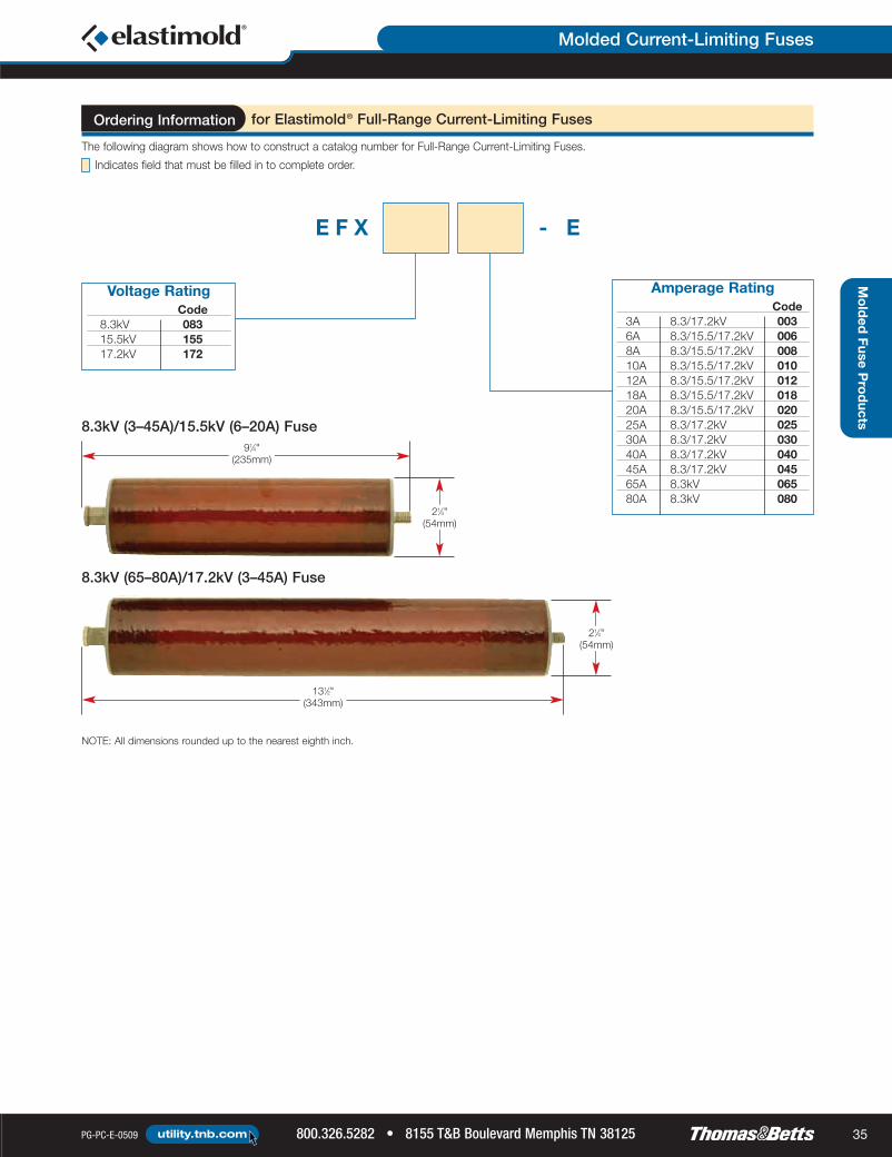
Molded Current-Limiting Fuses
PG-PC-E-0509 800.326.5282 • 8155 T&B Boulevard Memphis TN 38125utility.tnb.com 35
Molded
FuseProducts8.3kV (3–45A)/15.5kV (6–20A) Fuse
8.3kV (65–80A)/17.2kV (3–45A) Fuse
NOTE: All dimensions rounded up to the nearest eighth inch.
E F X - E
Voltage RatingCode
8.3kV 08315.5kV 15517.2kV 172
Amperage RatingCode
3A 8.3/17.2kV 0036A 8.3/15.5/17.2kV 0068A 8.3/15.5/17.2kV 00810A 8.3/15.5/17.2kV 01012A 8.3/15.5/17.2kV 01218A 8.3/15.5/17.2kV 01820A 8.3/15.5/17.2kV 02025A 8.3/17.2kV 02530A 8.3/17.2kV 03040A 8.3/17.2kV 04045A 8.3/17.2kV 04565A 8.3kV 06580A 8.3kV 080
for Elastimold® Full-Range Current-Limiting FusesOrdering Information
131⁄2"(343mm)
91⁄4"(235mm)
21⁄4"(54mm)
21⁄4"(54mm)
Indicates field that must be filled in to complete order.
The following diagram shows how to construct a catalog number for Full-Range Current-Limiting Fuses.
TnB_Elas-08_Guide_34-35:TnB_Elas-08_Guide_34-35 6/15/09 8:36 AM Page 35

Molded Current-Limiting Fuses
8155 T&B Boulevard Memphis TN 38125 • 800.326.5282 PG-PC-E-0509utility.tnb.com36
Mo
lded
Fuse
Pro
duc
ts
• 80A through 180A ratingsfor applications on 5kV systems
• 6A through 115A ratingsfor applications on 15kVgrounded Wye systems
• 6A through 100A ratingsfor applications on 25kVgrounded Wye systems
• 6A through 50A ratings for applicationson 35kV grounded Wye systems
Molded Current-Limiting FusesYou’re covered. These fusesprovide full-range protectionthrough 50kA interrupting current.
Molded Current-Limiting Fuses feature modular construction with a center
replaceable fuse section and interchangeable end fittings for elbow connection
or direct attachment to equipment-mounted bushings. The various end fittings
enable fuses to be applied throughout the system, including switchgear,
junctions, transformers, cable runs and taps.
Elastimold® Molded Current-Limiting Fuses are available in:
EPDM Molded Rubber Deadfront ConstructionInsulates, sheilds and eliminates exposted live parts. Lightweight fuses are fully sealed
and submersible.
Specially Designed Fuse Elements
with Built-In Low- and High-Current Provide full-range fault current protection through 50kA.
Interrupting Capability
Current-Limiting Protection — Fault Clearing Limits the system available fault current and dramatically
Occurs in Less than One-Half Cycle reduces stresses on equipment.
Internal Fuse Prevents corona and deterioration
Shield of the fuse element.
Modular Construction with a CenterEnables elbow connection or direct attachment to equipment-mounted
Replaceable Fuse Section andbushings on junctions, transformers, cable runs and taps.
Interchangeable End Fittings
Compact Suitable for padmount, subsurface or vault installations.
304 Stainless Steel Brackets and
Hold-Down Straps AvailableAccommodate a wide variety of mounting arrangements.
Benefits/DescriptionsFeatures
TnB_Elas-08_Guide_36-37:TnB_Elas-08_Guide_36-37 6/15/09 8:38 AM Page 36

Molded Current-Limiting Fuses
PG-PC-E-0509 800.326.5282 • 8155 T&B Boulevard Memphis TN 38125utility.tnb.com 37
Mo
lded
FuseP
rod
ucts
InterchangeableMolded Rubber
End Fittings
Assembled Fuse Unit
Replaceable Molded RubberCurrent-Limiting Fuse
Assembled Fuse Unit with OptionalWall-Mounting Bracket
Application Information
* 15.5kV L-G rated fuses require 75% grounded load to be applied on a 25kV system.**17.2kV L-G rated fuses require at least 75% grounded load to be applied on a 28kV system.NOTE: Fuse replacement requires the MCLF to be de-energized.
Fuses are only suitable for the system voltage class shown if the recovery voltageacross the fuse will not exceed its rated maximum voltage. For three-phase applications,this generally requires that protected transformers be gndY-gndY and have at least50% grounded load.
RatingsSystem Voltage Class (kV) 5 15 25/28* 35Rated Maximum Fuse Voltage (kV) 5.5 8.3/10** 15.5/17.2** 23Frequency (Hz) 50/60 50/60 50/60 50/60BIL Impulse Withstand (kV) 60 95 125/140 150One-Minute AC Withstand (kV) 34 34 40–45 50Fifteen-Minute DC Withstand (kV) 53 53 78 103Corona Extinction (kV) 11 11 19/21.5 26Symmetrical Interrupting Capability (Amp) 50,000 50,000 50,000 50,000Current Rating (Amp) 80–180 10–115 10–100 10–50
Construction: Submersible, non-venting, deadfront, corrosion resistantAmbient Temperature Range:
-30° C to 65° C for 6–50A fuses;-30° C to 40° C for >50A fuses.
Certified Tests
Elastimold® Molded Current-Limiting
Fuses have been designed and tested per
applicable portions of IEEE, ANSI, NEMA
and other industry standards, including:
ANSI C37.40 Standard for Current-Limiting Fuse Service ConditionsANSI C37.41 Standard for Current-Limiting Fuse Design & TestingANSI C37.47 Standard for Current-Limiting Fuse Ratings & SpecificationsANSI/IEEE 386 Standard for SeparableConnectors and Bushing Interfaces
TnB_Elas-08_Guide_36-37:TnB_Elas-08_Guide_36-37 6/15/09 8:38 AM Page 37

Molded Current-Limiting Fuses
8155 T&B Boulevard Memphis TN 38125 • 800.326.5282 PG-PC-E-0509utility.tnb.com38
Mo
lded
Fuse
Pro
duc
ts
NOTE: 1. Designs have a 50,000A all U/CERMSs Symmetrical Rating.2. 10–50A fuses have a Rated Maximum Application Temperature of 65° C, and 65–180A fuses have a Rated Maximum ApplicationTemperature of 40° C. (RMAT is the maximum temperature of the air in contact with the MCLF housing at which the fuses have been shownsuitable for use.)
3. Tabulated Maximum Total I2t values are for currents of 50,000A at the nominal voltage of the fuse. Fuses that have a Rated Maximum Voltage higherthan their Nominal Voltage Rating will have a higher I2t let-through when applied at voltages up to these higher values. For example, Maximum TotalI2t values are increased by approximately 30% when 8.3kV fuses are applied at 10kV and approximately 25% when 15.5kV fuses are used at 17.2kV.
4. Maximum total l2t values are reduced for currents below 50,000A. For example, at 10,000A, l2t values are approximately 15% less thanthe published values.
5. Peak arc voltages quoted are for 50,000A currents at the rated maximum voltage listed. Reduced currents and voltages will reduce the peakarc voltage. Consult the factory for further information.
6. Maximum continuous currents at higher ambient temperatures may be determined by derating the fuses by 0.2% per degree C over 25° C.For example: At 40° C, the derating would be 15 x 0.2 = 3%, making the maximum continuous current of a 20A fuse 23.0 x 0.97 = 22A.
Nominal Current Fuse Rated Maximum Peak Arc Minimum MaximumFuse Rating Catalog Maximum Continuous Voltage Melt l2t Total l2t
Voltage Number Voltage Current (kV) (AMP2-SEC)Rating (Amps) (kV) (2) (6) (5) (AMP2-SEC) (3) (4)
(kV) 25° C 40° C
80 M05CLF080 86 84 15 22,100 110,000100 M05CLF100 108 105 15 56,700 280,000
5.5 125 M05CLF125 5.5 137 133 15 109,200 530,000150 M05CLF150 159 154 15 176,000 860,000180 M05CLF180 185 180 15 259,000 1,270,00010 M15CLF010 14 13 28 800 4,00020 M15CLF020 23 22 26 1,620 11,00030 M15CLF030 10.0 35 33 26 5,250 30,000
8.3 40 M15CLF040 43 41 26 8,700 50,00050 M15CLF050 51 47 26 12,800 70,00065 M15CLF065 73 71 25 25,200 100,00080 M15CLF080 8.3 87 84 25 47,000 185,000100 M15CLF100 106 103 25 78,300 330,000115 M15CLF115 120 116 25 115,150 480,00010 M25CLF010 14 13 46 800 3,70020 M25CLF020 23 22 45 1,620 10,00030 M25CLF030 17.2 35 33 45 5,250 30,000
15.5 40 M25CLF040 43 41 45 8,700 50,00050 M25CLF050 47 45 45 12,800 70,00065 M25CLF065 68 66 40 25,200 110,00080 M25CLF080 15.5 88 84 40 54,400 255,000100 M25CLF100 100 100 40 80,000 380,00010 M35CLF010 14 13 61 800 4,80020 M35CLF020 23 22 60 1,620 13,000
23.0 30 M35CLF030 23.0 35 33 60 5,250 38,00040 M35CLF040 41 40 60 8,700 61,00050 M35CLF050 47 46 60 12,800 82,000
Electrical Characteristics of Encapsulated Fuses Used in MCLF
5.5
8.3
15.5
23.0
5.5
10.0
8.3
17.2
15.5
23.0
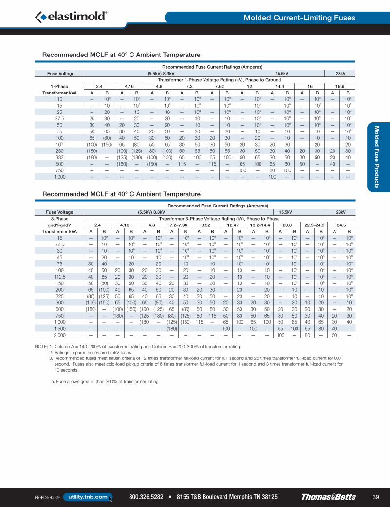
Molded Current-Limiting Fuses
PG-PC-E-0509 800.326.5282 • 8155 T&B Boulevard Memphis TN 38125utility.tnb.com 39
Mo
lded
FuseP
rod
ucts
NOTE: 1. Column A = 140–200% of transformer rating and Column B = 200–300% of transformer rating.2. Ratings in parentheses are 5.5kV fuses.3. Recommended fuses meet inrush criteria of 12 times transformer full-load current for 0.1 second and 25 times transformer full-load current for 0.01second. Fuses also meet cold-load pickup criteria of 6 times transformer full-load current for 1 second and 3 times transformer full-load current for10 seconds.
a. Fuse allows greater than 300% of transformer rating.
Recommended Fuse Current Ratings (Amperes)Fuse Voltage (5.5kV) 8.3kV 15.5kV 23kV
Transformer 1-Phase Voltage Rating (kV), Phase to Ground1-Phase 2.4 4.16 4.8 7.2 7.62 12 14.4 16 19.9
Transformer kVA A B A B A B A B A B A B A B A B A B10 — 10a — 10a — 10a — 10a — 10a — 10a — 10a — 10a — 10a
15 — 10 — 10a — 10a — 10a — 10a — 10a — 10a — 10a — 10a
25 — 20 — 10 — 10 — 10a — 10a — 10a — 10a — 10a — 10a
37.5 20 30 — 20 — 20 — 10 — 10 — 10a — 10a — 10a — 10a
50 30 40 20 30 — 20 — 10 — 10 — 10a — 10a — 10a — 10a
75 50 65 30 40 20 30 — 20 — 20 — 10 — 10 — 10 — 10a
100 65 (80) 40 50 30 50 20 30 20 30 — 20 — 10 — 10 — 10167 (100) (150) 65 (80) 50 65 30 50 30 50 20 30 20 30 — 20 — 20250 (150) — (100) (125) (80) (100) 50 65 50 65 30 50 30 40 20 30 20 30333 (180) — (125) (180) (100) (150) 65 100 65 100 50 65 30 50 30 50 20 40500 — — (180) — (150) — 115 — 115 — 65 100 65 80 50 — 40 —750 — — — — — — — — — — 100 — 80 100 — — — —1,000 — — — — — — — — — — — — 100 — — — — —
Recommended MCLF at 40° C Ambient Temperature
Recommended Fuse Current Ratings (Amperes)Fuse Voltage (5.5kV) 8.3kV 15.5kV 23kV
3-Phase Transformer 3-Phase Voltage Rating (kV), Phase to PhasegndY-gndY 2.4 4.16 4.8 7.2–7.96 8.32 12.47 13.2–14.4 20.8 22.9–24.9 34.5
Transformer kVA A B A B A B A B A B A B A B A B A B A B15 — 10a — 10a — 10a — 10a — 10a — 10a — 10a — 10a — 10a — 10a
22.5 — 10 — 10a — 10a — 10a — 10a — 10a — 10a — 10a — 10a — 10a
30 — 10 — 10a — 10a — 10a — 10a — 10a — 10a — 10a — 10a — 10a
45 — 20 — 10 — 10 — 10a — 10a — 10a — 10a — 10a — 10a — 10a
75 30 40 — 20 — 20 — 10 — 10 — 10a — 10a — 10a — 10a — 10a
100 40 50 20 30 20 30 — 20 — 10 — 10 — 10 — 10a — 10a — 10a
112.5 40 65 20 30 20 30 — 20 — 20 — 10 — 10 — 10a — 10a — 10a
150 50 (80) 30 50 30 40 20 30 — 20 — 10 — 10 — 10a — 10a — 10a
200 65 (100) 40 65 40 50 20 30 20 30 — 20 — 20 — 10 — 10 — 10a
225 (80) (125) 50 65 40 65 30 40 30 50 — 20 — 20 — 10 — 10 — 10a
300 (100) (150) 65 (100) 65 (80) 40 50 30 50 20 30 20 30 — 20 10 20 — 10500 (180) — (100) (150) (100) (125) 65 (80) 50 80 30 50 30 50 20 30 20 30 — 20750 — — (180) — (125) (180) (80) (125) 80 115 50 80 50 65 30 50 30 40 20 301,000 — — — — (180) — (125) (180) 115 — 65 100 65 100 50 65 40 65 30 401,500 — — — — — — (180) — — — 100 — 100 — 65 100 65 80 40 —2,000 — — — — — — — — — — — — — — 100 — 80 — 50 —
Recommended MCLF at 40° C Ambient Temperature
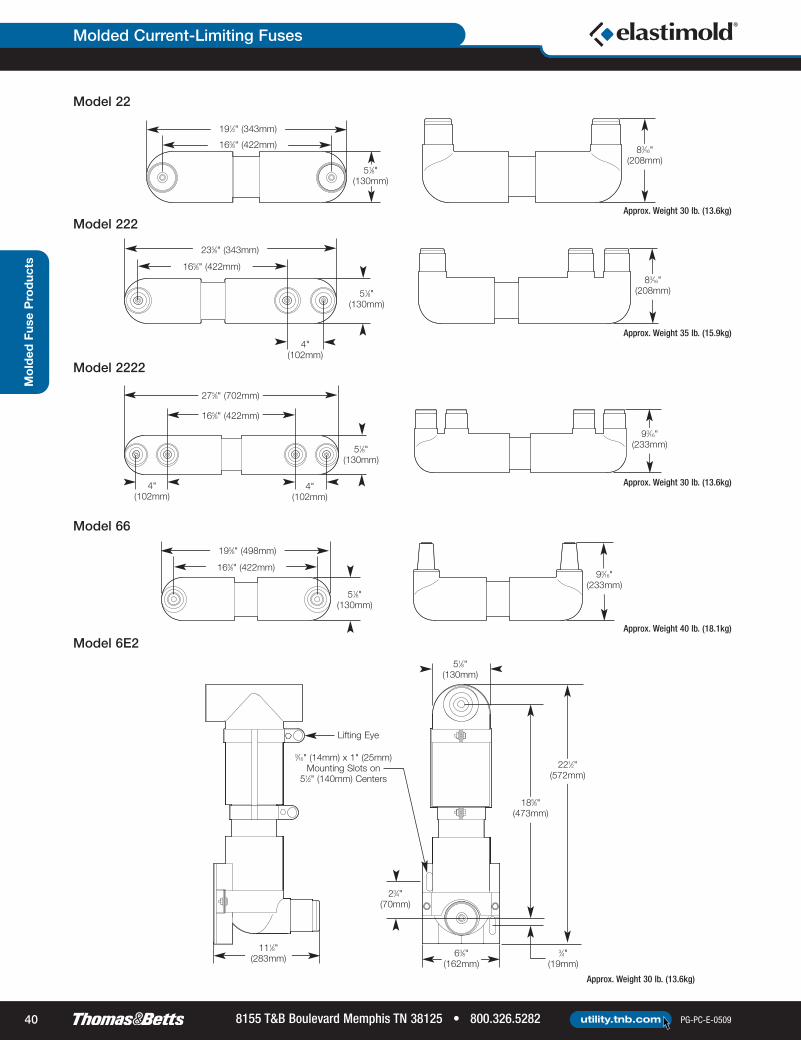
Molded Current-Limiting Fuses
8155 T&B Boulevard Memphis TN 38125 • 800.326.5282 PG-PC-E-0509utility.tnb.com40
Mo
lded
Fuse
Pro
duc
ts
Approx. Weight 30 lb. (13.6kg)
165⁄8" (422mm)
191⁄2" (343mm)
51⁄8"(130mm)
83⁄16"(208mm)
83⁄16"(208mm)
93⁄16"(233mm)
4"(102mm)
165⁄8" (422mm)
165⁄8" (422mm)
235⁄8" (343mm)
275⁄8" (702mm)
51⁄8"(130mm)
51⁄8"(130mm)
4"(102mm)
4"(102mm)
165⁄8" (422mm)
195⁄8" (498mm)
51⁄8"(130mm)
93⁄16"(233mm)
Lifting Eye
9⁄16" (14mm) x 1" (25mm)Mounting Slots on51⁄2" (140mm) Centers
23⁄4"(70mm)
3⁄4"(19mm)
111⁄8"(283mm) 63⁄8"
(162mm)
221⁄2"(572mm)
185⁄8"(473mm)
51⁄8"(130mm)
Model 22
Model 222
Model 2222
Model 66
Model 6E2
Approx. Weight 35 lb. (15.9kg)
Approx. Weight 30 lb. (13.6kg)
Approx. Weight 40 lb. (18.1kg)
Approx. Weight 30 lb. (13.6kg)
TnB_Elas-08_Guide_40-41:TnB_Elas-08_Guide_40-41 6/15/09 8:41 AM Page 40

Molded Current-Limiting Fuses
PG-PC-E-0509 800.326.5282 • 8155 T&B Boulevard Memphis TN 38125utility.tnb.com 41
Cap
acitorC
ontro
ls
Mo
lded
FuseP
rod
ucts
NOTE: Other models are available such as 26.
111⁄8"(283mm)
9⁄16" (14mm) x 1" (25mm)Mounting Slots on51⁄2" (140mm) Centers
Lifting Eye
51⁄8"(130mm)
23⁄4"(70mm)
63⁄8"(162mm)
221⁄2"(572mm)
185⁄8"(473mm)
1⁄2"(13mm)
Model 6E6
Approx. Weight 30 lb. (13.6kg)
The following diagram shows how to construct a catalog number for a Molded Current-Limiting Fuse:
for Elastimold® Molded Current-Limiting FusesOrdering Information
M C L F - -
Voltage ClasskV Code
5.0kV 515.0kV 1525.0kV 2535.0kV 35
Mounting BracketsBracketCode
Wall Mounting Bracket with Parking Stands WMBand Bolted Style Hold Down Straps (HDS)Wall Mounting Bracket with Parking Stands WMBQand Quick Release Style Hold Down Straps (QRS)
Indicates field that must be filled in to complete order.
BushingsBushingCode
200A Bushing Wells both ends 22200A Bushing Well on one end and two 222200A Bushing Wells on the other endTwo 200A Bushing Wells on both ends 2222600A Bushings on both ends 66600A Elbow Connector on one end and a 200A 6E2Bushing Well on the other end; this arrangementis not available at 35kV600A Elbow Connector on one end and a 600A 6E6Bushing on the other end; this arrangement isnot available at 35kV
AmperesVoltage Class Amperage
5kV 15kV 25kV 35kV Code— 10 10 10 10— 20 20 20 20— 30 30 30 30— 40 40 40 40— 50 50 50 50— 65 65 — 6580 80 80 — 80100 100 100 — 100— 115 — — 115125 — — — 125150 — — — 150185 — — — 185
See page 42 for additional options.See page 38 for additional options.
See page 38 for additional options.
See outline drawings preceding this chart for additional details.
TnB_Elas-08_Guide_40-41:TnB_Elas-08_Guide_40-41 6/15/09 8:41 AM Page 41

Molded Current-Limiting Fuses
8155 T&B Boulevard Memphis TN 38125 • 800.326.5282 PG-PC-E-0509utility.tnb.com42
Mo
lded
Fuse
Pro
duc
ts
15 to 60˚
Approx. Weight 8 lb. (3.6 kg) 9⁄16" (14mm) x 1" (25mm)Mounting Slots
63⁄4"(171mm)
Optional WMB Mounting Bracket with AdjustableParking Stands for Vertical Mounting and Fuse Hold-Down Strips Optional — TMA Universal Tilt Mounting
51⁄2"(140mm)
Mounting Options
293⁄4" (756mm)
323⁄4" (832mm)
IEEE 386-1995OPTION NO. Description System Voltage Class Interface Reference
EF2 200A Bushing Well End Fitting 5, 15, 25, 35 Figure 3EF22 Double 200A Bushing Well End Fitting 5, 15, 25, 35 Figure 3EF6 600A Bushing End Fitting 5, 15, 25, 35 Figures 11 and 13EF6E 600A Elbow Connector End Fitting 5, 15, 25 Figure 11
NOTE: The option number may be added as a suffix to the MCLF catalog number.
MCLF-ADTAssembly/Disassembly Tool
3⁄8" (10mm)Sq. Drive
3⁄16" (5mm) Hex
Optional Fuse Mountings
OPTION NO. Description
HDS Bolted-Style Hold-Down Strap (Qty: 1 required per end fitting)QRS Quick-Release Style Hold-Down Strap (Qty: 1 required per end fitting)WMB Wall-Mounting Bracket with Parking Stands and Bolted-Style Hold-Down StrapsWMBQ Wall-Mounting Bracket with Parking Stands and Quick-Release Style Hold-Down Straps
SMBSupport Mounting Bracket for use with Models 6E2 or 6E6 end-fitting arrangements;includes Bolted-Style Hold-Down Strap
TMA-EMTilt Mounting Adapter; bolts to bottom of Wall-Mounting Bracket WMB or WMBQ to enable up to 60º anglemounting (Qty: 2 required per installation)
NOTE: EF6E is equipped with a standard through-hole spade lug (Type 03700). Use this table only if end fittingsare to be ordered and shipped separately from the fuse. See pages 40–41 for assembled units.
End Fitting Catalog Numbers
Other Options
CAT. NO. Description
MCLF-ADTHex Wrench for set screw removal and replacement when disassembling
end fittings. Supplied as standard with replacement fuses.
TnB_Elas-08_Guide_42-43:TnB_Elas-08_Guide_42-43 6/15/09 8:42 AM Page 42

Molded Canister Fuses
PG-PC-E-0509 800.326.5282 • 8155 T&B Boulevard Memphis TN 38125utility.tnb.com 43
Mo
lded
FuseP
rod
ucts
Nominal Voltage Rating (kV) 8.3 15.5 23.0Rated Maximum Voltage (kV) 8.8/10.0 15.5/17.2** 23.0Frequency (Hz) 50–60 50–60 50–60Current Rating (Amps) 3–80 3–65 6–50Rated Maximum InterruptingCurrent (Sym. Amps)
50,000 50,000 50,000
System Voltage Class (kV) 15 25/28 35Maximum Line-to-Ground Voltage (kV) 8.8/10.0 15.5/17.2 23BIL Impulse Withstand (kV) 95 125/140 150One-Minute AC Withstand (kV) 34 40–45 50Fifteen-Minute DC Withstand (kV) 53 78 103Corona Extinction (kV) 11 19–21.5 26Maximum Continuous Current (Amps) 200* 200* 200*Momentary Current (kA) 10* 10* 10*
The MCAN Molded Canister Fuse is a compact, lightweight EPDM molded rubber fuse enclosure
package. MCAN fuse canisters are maintenance-free, completely sealed and submersible. Designs
are deadfront, using molded rubber to insulate, shield and eliminate exposed live parts. Units are
ideally suited for padmount, subsurface or vault applications, for systems through 35kV gndY–gndY.
The MCAN Molded Canister Fuse will accommodate and has been thoroughly tested with Hi-Tech®
Trans-Guard® FX fuses. Contact Thomas & Betts before using fuses from other manufacturers.
MCAN Molded Canister FuseCompletely sealed and insulated forpadmount, subsurface or vault applicationsthrough 35kV gndY–gndY.
EPDM Molded RubberInsulates, shields and eliminates live parts. Fuses are fully sealed and submersible.
Deadfront Construction
Compact Suitable for padmount, subsurface or vault installations.
Modular Construction Enables elbow connection or direct attachment to equipment-mounted bushings.
Neon Voltage Indicators (V2) Attached to elbow test points to provide quick and convenient blown-fuse indication.
Various End Fittings and BushingsMake for flexible installation on switchgear, junctions, transformers,cable runs and taps.
Replaceable Fuse Section Ease of fuse replacement without full removal from installation.
Current-Limiting Protection — Fault Clearing Limits the system available fault current and dramaticallyOccurs in Less than One-Half Cycle reduces stresses on equipment.
304 Stainless Steel Mounting Brackets andAccommodate a wide variety of mounting arrangements.
Wall-Mounted Parking Stands Available
Benefits/DescriptionsFeatures
Fuse Canister Ratings
* Without fuse.** The 15.5kV L-G rated fuses require at least 75% grounded load
to be applied on a 25kV system.NOTE: Fuse replacement requires the MCAN to be de-energized.
Fuse Ratings
Certified Tests
Elastimold® Molded Canister Fuses have been designed and tested
per applicable portions of IEEE, ANSI, NEMA and other industry
standards, including:
ANSI C37.40 Standard for Current-Limiting Fuse Service ConditionsANSI C37.41 Standard for Current-Limiting Fuse Design & TestingANSI C37.47 Standard for Current-Limiting Fuse Ratings &SpecificationsANSI/IEEE 386 Standard for Separable Connectors & BushingInterfaces
Application InformationConstruction: Submersible, corrosion resistant, fully shieldedAmbient Temperature Range: -30° C to 65° C
TnB_Elas-08_Guide_42-43:TnB_Elas-08_Guide_42-43 6/15/09 8:42 AM Page 43

Molded Canister Fuses
8155 T&B Boulevard Memphis TN 38125 • 800.326.5282 PG-PC-E-0509utility.tnb.com44
Mo
lded
Fuse
Pro
duc
ts
FX Current-Limiting Fuse
Low-Current Interruption Element(Includes Patented Damage Sensor)
Tin-PlatedBrass Cap
Filled with CompactedQuartz Sand
High-CurrentInterruption Element
EpoxyJoint
200A Bushing Wells
600A Bushing
600A Elbow
200A Bushing Well
200A Bushing Well
FX Full-RangeCurrent-Limiting
Fuse
Latching Lever
End Plugwith Eye
Mounting Feet
Molded EPDMRubber Insulationand Shielding
CableConnectionBushings orWells
CableConnectionBushings orWells
Soldered ElectricalConnection and Sealing
Mica ElementSupport
Resin-Rich Filament WoundGlass/Epoxy Body
WeldedElementJoints
0.625"(15.9mm)

Molded Canister Fuses
PG-PC-E-0509 800.326.5282 • 8155 T&B Boulevard Memphis TN 38125utility.tnb.com 45
Mo
lded
FuseP
rod
ucts
NOTE: 1. Column A = 140–200% of transformer rating and Column B = 200–300% of transformer rating.2. 8.3kV, 3–50A fuses are used in mounting code 4 canisters; 8.3kV 65–80A fuses and 15.5kV 3–50A fuses are used in mounting
code 5 canisters; 15.5kV 65A fuse and 23kV 3–50A fuses are used in mounting code 6 canisters.3. Recommended fuses meet inrush criteria of 12 times transformer full-load current for 0.1 second and 25 times transformer full-load current
for 0.01 second. Fuses also meet cold-load pickup criteria of 6 times transformer full-load current for 1 second and 3 times transformerfull-load current for 10 seconds.
a. Fuse allows greater than 300% of transformer rating.
Recommended Fuse Current Ratings (Amperes)Fuse Voltage 8.3kV 15.5kV 23kV
Transformer 1-Phase Voltage Rating (kV), Phase to Ground1-Phase 2.4 4.16 4.8 7.2 7.62 12 14.4 16 19.9
Transformer kVA A B A B A B A B A B A B A B A B A B10 — 6 — 6a — 3 — 3a — 3a — 3a — 3a — 3a — 6a
15 — 10 — 6 — 6a — 3 — 3 — 3a — 3a — 3a — 6a
25 12 20 8 10 — 8 — 6 — 6 — 3 — 3 — 3 — 6a
37.5 20 30 12 18 — 12 — 8 — 8 — 6a — 6a — 6a — 6a
50 25 50 18 25 12 20 10 12 — 10 — 6 — 6 — 6a — 6a
75 50 65 25 40 20 30 12 20 12 20 — 10 — 8 — 8 — 6100 65 80 30 50 25 50 18 25 18 25 — 12 10 12 — 10 — 8167 — — 65 80 65 80 30 50 30 50 18 25 18 25 12 20 — 12250 — — — — 80 — 65 80 50 65 25 50 25 40 20 30 18 25333 — — — — — — 80 — 65 — 50 65 30 65 25 50 20 30500 — — — — — — — — — — 65 — 65 — 50 — 40 —
Recommended FX: in MCAN at 40° C Ambient Temperature
Recommended Fuse Current Ratings (Amperes)Fuse Voltage 8.3kV 15.5kV 23kV
3-Phase Transformer 3-Phase Voltage Rating (kV), Phase to PhasegndY-gndY 2.4 4.16 4.8 7.2–7.96 8.32 12.47 13.2–14.4 20.8 22.9–24.9 34.5
Transformer kVA A B A B A B A B A B A B A B A B A B A B15 — 6 — 3 — 3 — 3a — 3a — 3a — 3a — 6a — 3a — 6a
22.5 — 8 — 6a — 6a — 3 — 3 — 3a — 3a — 6a — 3a — 6a
30 10 12 — 6 — 6 — 6a — 3 — 3a — 3 — 6a — 3a — 6a
45 12 20 — 10 — 8 — 6 — 6a — 3 — 3 — 6a — 3a — 6a
75 25 40 12 20 12 18 — 8 — 8 — 6 — 6 — 6a — 3 — 6a
100 30 50 18 25 18 25 — 12 — 10 — 8 — 8 — 6a — 6a — 6a
112.5 40 65 20 30 18 25 — 18 — 12 — 8 — 8 — 6a — 6a — 6a
150 65 80 25 50 25 40 12 25 12 18 — 10 — 10 — 6 — 6 — 6a
200 80 — 40 65 30 50 18 30 18 25 12 18 — 12 — 8 — 8 — 6225 — — 50 65 40 65 20 40 20 30 12 20 12 20 — 10 — 8 — 6300 — — 65 80 65 80 25 50 25 50 18 25 18 25 — 12 — 12 — 8500 — — — — — — 30 80 65 80 30 50 30 50 18 25 18 25 — 12750 — — — — — — 65 — 80 — 65 80 50 — 25 50 25 50 18 251,000 — — — — — — — — — — 80 — — — 40 65 40 — 25 301,500 — — — — — — — — — — — — — — 65 — — — 40 —
Recommended FX: in MCAN at 40° C Ambient Temperature

Molded Canister Fuses
8155 T&B Boulevard Memphis TN 38125 • 800.326.5282 PG-PC-E-0509utility.tnb.com46
Mol
ded
Fuse
Pro
duct
s
NOTE: 1. Designs have a 50,000A rms Symmetrical Rating (except for 3A, 15.5kV which was tested at 44kA maximum).
2. Fuses have a Rated Maximum Application Temperature of 65° C. (RMAT is the maximum temperature of the air in contact with theMCAN housing, at which fuses have been shown to be suitable for use.)
3. Tabulated Maximum Total I2t values are for currents of 50,000A at the nominal voltage of the fuse. Fuses that have a RatedMaximum Voltage higher than their Nominal Voltage Rating willhave a higher I2t let-through when applied at voltages up to thesehigher values. For example, Maximum Total I2t values areincreased by approximately 30% when 8.3kV fuses are applied at 10kV and approximately 25% when 15.5kV fuses are used at 17.2kV.
4. Maximum total I2t values are reduced for currents below 50,000A. For example, at 10,000A, maximum total I2t values are approximately 15% less than the published values.
5. Peak arc voltages quoted are for 50,000A currents at the rated maximumvoltage listed. Reduced currents and voltages will reduce the peak arcvoltage. Consult the factory for further information.
6. Maximum continuous currents at higher ambient temperatures may bedetermined by de-rating the fuses by 0.2% per degree C over 25° C. For example: At 65° C, the de-rating would be 40 x 0.2 = 8%, making the maximum continuous current of a 30A fuse 34 x 0.92 = 31A.
7. Reduction in the long time melting current of the fuses (approximately one hour and longer) due to higher ambient temperatures is the same as described above in Note #6. See time-current characteristics formelting characteristics in this time region.
Maximum Peak Arc MaximumNominal Current Rated Continuous Current Voltage Minimum Total l2t
Fuse Voltage Rating Fuse Maximum (2) (6) (kV) Melt l2t (AMP2-SEC)Rating (kV) (Amps) CAT. NO. Voltage (kV) 25° C 40° C 65° C (5) (AMP2-SEC) (3) (4)
3 HTFX230003 4.3 4.2 3.9 30 100 3506 HTFX230006 9.5 9 8.5 32 620 2,7008 HTFX230008 11.5 11 10.5 28 800 4,000
10 HTFX230010 13.5 13 12.5 28 800 4,00012 HTFX230012 17.5 17 16 26 920 8,00018 HTFX230018 10 19.5 19 18 26 1,310 9,500
8.3 20 HTFX230020 24 23 21.5 26 1,620 11,00025 HTFX230025 29.5 28.5 27 26 3,660 22,00030 HTFX230030 34 33 31 26 5,250 30,00040 HTFX230040 40 39 36.5 26 8,700 50,00050 HTFX230050 45.5 44 42 26 12,800 70,00065 HTFX230065
8.870 68 64.5 23 34,000 200,000
80 HTFX230080 80 77.5 73.5 22 51,200 280,0003 HTFX240003 4.3 4.2 3.9 51 100 5106 HTFX240006 9.5 9 8.5 54 620 2,6008 HTFX240008 11.5 11 10.5 46 800 3,700
10 HTFX240010 13.5 13 12.5 46 800 3,70012 HTFX240012 17.5 17 16 43 920 6,500
15.518 HTFX240018 17.2 19.5 19 18 45 1,310 8,00020 HTFX240020 24 23 21.5 45 1,620 10,00025 HTFX240025 29.5 28.5 27 45 3,660 22,00030 HTFX240030 34 33 31 45 5,250 30,00040 HTFX240040 40 39 36.5 45 8,700 50,00050 HTFX240050 44.5 43 40 45 12,800 70,00065 HTFX240065 15.5 57.6 56 54.5 39 28,300 164,0006 HTFX250006 9.5 9 8.5 67 620 3,1008 HTFX250008 11.5 11 10.5 61 800 4,800
10 HTFX250010 13.5 13 12.5 61 800 4,80012 HTFX250012 17.5 17 16 60 920 8,300
2318 HTFX250018
2319.5 19 18 60 1,310 11,200
20 HTFX250020 24 23 21.5 60 1,620 13,00025 HTFX250025 29.5 28.5 27 60 3,660 28,00030 HTFX250030 34 33 31 60 5,250 38,00040 HTFX250040 38.5 37 35 60 8,700 61,00050 HTFX250050 44.5 43 40 60 12,800 82,000
Electrical Characteristics of Hi-Tech® FX Fuses inside MCAN Canisters
TnB_Elas-08_Guide_46-47:TnB_Elas-08_Guide_46-47 6/15/09 8:44 AM Page 46
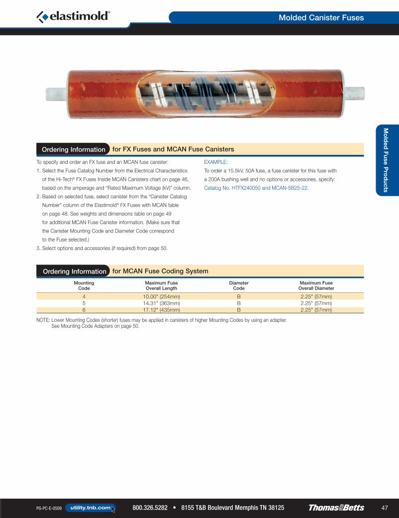
Molded Canister Fuses
PG-PC-E-0509 800.326.5282 • 8155 T&B Boulevard Memphis TN 38125utility.tnb.com 47
Molded Fuse P
roducts
NOTE: Lower Mounting Codes (shorter) fuses may be applied in canisters of higher Mounting Codes by using an adapter. See Mounting Code Adapters on page 50.
To specify and order an FX fuse and an MCAN fuse canister:
1. Select the Fuse Catalog Number from the Electrical Characteristics
of the Hi-Tech® FX Fuses Inside MCAN Canisters chart on page 46,
based on the amperage and “Rated Maximum Voltage (kV)” column.
2. Based on selected fuse, select canister from the “Canister Catalog
Number” column of the Elastimold® FX Fuses with MCAN table
on page 48. See weights and dimensions table on page 49
for additional MCAN Fuse Canister information. (Make sure that
the Canister Mounting Code and Diameter Code correspond
to the Fuse selected.)
3. Select options and accessories (if required) from page 50.
EXAMPLE:
To order a 15.5kV, 50A fuse, a fuse canister for this fuse with
a 200A bushing well and no options or accessories, specify:
Catalog No. HTFX240050 and MCAN-5B25-22.
for FX Fuses and MCAN Fuse CanistersOrdering Information
Mounting Maximum Fuse Diameter Maximum Fuse Code Overall Length Code Overall Diameter
4 10.00" (254mm) B 2.25" (57mm)5 14.31" (363mm) B 2.25" (57mm)6 17.12" (435mm) B 2.25" (57mm)
for MCAN Fuse Coding SystemOrdering Information
TnB_Elas-08_Guide_46-47:TnB_Elas-08_Guide_46-47 6/15/09 8:44 AM Page 47

Molded Canister Fuses
8155 T&B Boulevard Memphis TN 38125 • 800.326.5282 PG-PC-E-0509utility.tnb.com48
Mo
lded
Fuse
Pro
duc
ts
for Hi-Tech® FX Fuses with MCANOrdering Information
C
B
D
A
Nominal Rated (A) (B) (C) (D)Fuse Current Maximum Overall Overall Contact Body Fuse
Voltage Rating Fuse Voltage Mounting Diameter Diameter Length Length Length Canister WeightRating (kV) (Amps) CAT. NO. (kV) Code Code in. (mm) in. (mm) in. (mm) in. (mm) CAT. NO. lb. (kg)
3 HTFX2300036 HTFX2300068 HTFX23000810 HTFX23001012 HTFX230012
MCAN-4B15-22
18 HTFX230018 10.0 4 B2.25 10.0 1.02 7.96 MCAN-4B15-66 3.00
20 HTFX230020(57) (254) (26) (202) MCAN-4B15-6E2 (1.3)
8.3 25 HTFX230025MCAN-4B15-6E6
30 HTFX23003040 HTFX23004050 HTFX230050
65 HTFX230065MCAN-5B15-22
8.8 5 B2.25 14.31 1.02 12.27 MCAN-5B15-66 4.25
80 HTFX230080(57) (363) (26) (312) MCAN-5B15-6E2 (1.9)
MCAN-5B15-6E63 HTFX2400036 HTFX2400068 HTFX24000810 HTFX24001012 HTFX240012
MCAN-5B25-22
18 HTFX240018 17.2 5 B2.25 14.31 1.02 12.27 MCAN-5B25-66 4.25
15.5 20 HTFX240020(57) (363) (26) (312) MCAN-5B25-6E2 (1.9)
25 HTFX240025MCAN-5B25-6E6
30 HTFX24003040 HTFX24004050 HTFX240050
65 HTFX240065 15.5 6 B2.25 17.12 1.02 15.09
MCAN-6B25-224.75
(57) (435) (26) (383) (2.2)6 HTFX2500068 HTFX25000810 HTFX25001012 HTFX250012
23.018 HTFX250018
23.0 6 B2.25 17.12 1.02 15.09
MCAN-6B35-664.75
20 HTFX250020 (57) (435) (26) (383) (2.2)25 HTFX25002530 HTFX25003040 HTFX25004050 HTFX250050
NOTE: For 5kV systems, use the 8.3kV rated fuses.
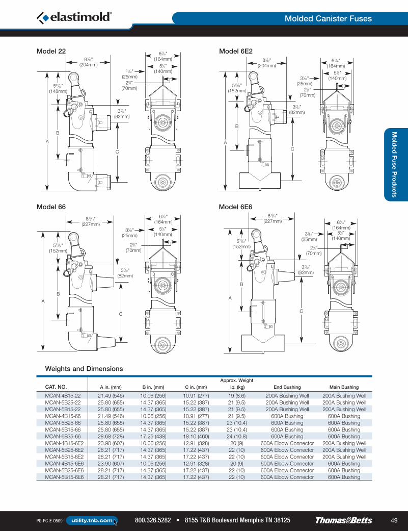
Molded Canister Fuses
PG-PC-E-0509 800.326.5282 • 8155 T&B Boulevard Memphis TN 38125utility.tnb.com 49
Approx. WeightCAT. NO. A in. (mm) B in. (mm) C in. (mm) lb. (kg) End Bushing Main Bushing
MCAN-4B15-22 21.49 (546) 10.06 (256) 10.91 (277) 19 (8.6) 200A Bushing Well 200A Bushing WellMCAN-5B25-22 25.80 (655) 14.37 (365) 15.22 (387) 21 (9.5) 200A Bushing Well 200A Bushing WellMCAN-5B15-22 25.80 (655) 14.37 (365) 15.22 (387) 21 (9.5) 200A Bushing Well 200A Bushing WellMCAN-4B15-66 21.49 (546) 10.06 (256) 10.91 (277) 21 (9.5) 600A Bushing 600A BushingMCAN-5B25-66 25.80 (655) 14.37 (365) 15.22 (387) 23 (10.4) 600A Bushing 600A BushingMCAN-5B15-66 25.80 (655) 14.37 (365) 15.22 (387) 23 (10.4) 600A Bushing 600A BushingMCAN-6B35-66 28.68 (728) 17.25 (438) 18.10 (460) 24 (10.8) 600A Bushing 600A BushingMCAN-4B15-6E2 23.90 (607) 10.06 (256) 12.91 (328) 20 (9) 600A Elbow Connector 200A Bushing WellMCAN-5B25-6E2 28.21 (717) 14.37 (365) 17.22 (437) 22 (10) 600A Elbow Connector 200A Bushing WellMCAN-5B15-6E2 28.21 (717) 14.37 (365) 17.22 (437) 22 (10) 600A Elbow Connector 200A Bushing WellMCAN-4B15-6E6 23.90 (607) 10.06 (256) 12.91 (328) 20 (9) 600A Elbow Connector 600A BushingMCAN-5B25-6E6 28.21 (717) 14.37 (365) 17.22 (437) 22 (10) 600A Elbow Connector 600A BushingMCAN-5B15-6E6 28.21 (717) 14.37 (365) 17.22 (437) 22 (10) 600A Elbow Connector 600A Bushing
527⁄32"(148mm)
A
B
51⁄2"(140mm)
23⁄4"(70mm)
67⁄16"(164mm)
31⁄64"(25mm)
37⁄32"(82mm)
C
81⁄32"(204mm)
553⁄64"(152mm)
A
B
51⁄2"(140mm)
23⁄4"(70mm)
67⁄16"(164mm)
31⁄64"(25mm)
37⁄32"(82mm)
C
815⁄16"(227mm)
553⁄64"(152mm)
A
B
51⁄2"(140mm)
23⁄4"(70mm)
67⁄16"(164mm)
31⁄64"(25mm)
37⁄32"(82mm)
C
81⁄32"(204mm)
553⁄64"(152mm)
A
B
51⁄2"(140mm)
23⁄4"(70mm)
67⁄16"(164mm)
31⁄64"(25mm)
37⁄32"(82mm)
C
815⁄16"(227mm)
Weights and Dimensions
Mo
lded
FuseP
rod
ucts
Model 22 Model 6E2
Model 66 Model 6E6

Molded Canister Fuses
8155 T&B Boulevard Memphis TN 38125 • 800.326.5282 PG-PC-E-0509utility.tnb.com50
MCAN Molded Canister Fuse Options and Accessories
Neon voltage indicators provide quick and convenient indication of an energized circuit when
they are mounted to the test-point provision on MCAN elbow connectors. The voltage indicator
illuminates with a flashing neon light when the elbow connector is energized. If the fuse blows,
the neon lights on the load-side elbows stop flashing.
A mounting code adapter is used to extend the fuse end cap ferrule so that a shorter fuse may
be installed in a higher-number coded canister. For example, a 4B size fuse can be used in
a 5B canister when an MCAN 4-5 adapter is used.
Parking stands can be mounted adjacent to an MCAN Fuse Canister, enabling attachment
of additional accessories to ground, isolate and test the elbow cable connectors.
Elastimold® multi-point junctions can be utilized to create custom switchgear lineups
consisting of MVS switches, MVI fault interrupters, MCLF current-limiting fuses, MCAN fuse
canisters, fused elbows, elbow arresters and other molded products. The junction enables
easy assembly and interconnection of components into fully shielded, submersible, compact
arrangements.
CAT. NO. Description
V2 Capacitive Test Point, Voltage Indicator
for Elastimold® Voltage IndicatorsOrdering Information
Voltage Indicators
Mounting Code Adapters
CAT. NO. Description
MCAN 4-5 Code 4B Size Fuse to a Code 5B CanisterMCAN 4-6 Code 4B Size Fuse to a Code 6B CanisterMCAN 5-6 Code 5B Size Fuse to a Code 6B Canister
for Elastimold® Mounting Code AdaptersOrdering Information
Parking Stands
CAT NO. Description
160WMPS Wall-Mount Parking Stand
SUFFIX NO. Description
-PS Parking Stand between Bushings
for Elastimold® Parking StandsOrdering Information
Switchgear Assemblies
Mo
lded
Fuse
Pro
duc
ts

QUICK REFERENCE
Elastimold®
Surge Arresters page(s)
MOV Surge Arresters . . . . . 52–57
When lightning strikes, be sureyour system is protected by MOVUnderground Surge Arresters.Our Metal Oxide Varistor (MOV) Surge Arresters provide high-voltage lightning and switching surgeprotection for transformers, cables and other components in underground power distribution systems.They minimize damaging surges by improving protective margins.
PG-PC-E-0509 800.326.5282 • 8155 T&B Boulevard Memphis TN 38125utility.tnb.com 51
Surg
eA
rrestersOverview

Surge Arresters
8155 T&B Boulevard Memphis TN 38125 • 800.326.5282 PG-PC-E-0509utility.tnb.com52
Sur
ge
Arr
este
rs
IEEE 386 Interfaces; IEEE C62.11Provide convenient energized connection with other 200A loadbreakor deadbreak components.
EPDM Molded Rubber Construction Fully shielded and fully submersible for a variety of applications.
Compact Size Enables installation in your existing cabinetry, saving you money.
Three Styles of Arresters Available Surge arresters fit your application and are easy to install.
Direct Connection on PSA and BSA Versions Eliminates the need for additional accessories, saving even more money.
Withstands 10,000 amps for 10 cycles without fusing.#4 AWG Ground Lead Tethered to the Jacket Controls end plug when ejected, preventing uncontrolled trajectory.
Maintains the housing shield ground connection after failure.
Benefits/DescriptionsFeatures
Following each of the preceding tests, MOV Arresters demonstrate thermalrecovery at MCOV.
for Metal Oxide Varistor (MOV) Surge Arresters
High Current, Short Duration All MOV Arresters withstandtwo discharges of 40kA crest
Low Current, Long Duration All MOV Arresters withstand20 surges of 75A/2,000microseconds duration
Duty Cycle Test All MOV Arresters withstand 22operations of 5kA crest at 8 x 20microseconds duration whileenergized at rated voltage for theinitial 20 operations and at maximumcontinuous operating voltage (MCOV)for the final two operations
Ratings
Voltage surges that exceed the BIL rating of the distribution systemcomponents will cause damage to the installed equipment. To protectagainst these surges, overhead surge arresters are widely used. Theirapplication is understood since overhead lines and equipment are directlyaffected by voltage surges (e.g. lightning). However, the use of overheadarresters alone will not guarantee proper protection of the insulation inthe underground portion of an electrical distribution system. The let-through surge from the riser pole arresters into the underground systemscould be enough to cause damage to the aging equipment insulation.
Elastimold® MOV Surge Arresters provide high-voltage lightning andswitching surge protection of transformers, cable, equipment and othercomponents typically located on underground power distributionsystems. Proper placement, voltage selection and coordination withriser pole arresters minimize damaging surge voltages by improvingprotective margins.
Typical applications includeinstalling an arrester at the endof a radial system or at both endsof an open point on a loop system. Additional arresters can be added atstrategic locations upstream from the end point for optimum protection.
Metal Oxide Varistor (MOV) Surge Arresters are available in three styles:Elbow (ESA), Parking Stand (PSA) and Bushing (BSA). The PSA and BSAarresters permit direct connection, eliminating the need for additionalaccessories. ESA Elbow Arresters are also available with a 200Adeadbreak interface for mating with other deadbreak accessories.
The following page highlights the different installation options usingBushing and Parking Stand Arresters where Elbow Arresters are normallyused. Using BSAs and PSAs will contribute to saving space insidetransformers and improving operability.
Metal Oxide Varistor (MOV) Surge Arresters
Fully shielded, fully submersible for convenientenergized connection with 200A loadbreakor deadbreak components up to 35kV.

Surge Arresters
PG-PC-E-0509 800.326.5282 • 8155 T&B Boulevard Memphis TN 38125utility.tnb.com 53
Surg
eA
rresters
PSA™ ParkingSurge Arrester
BSA™ BushingSurge Arrester
LoadbreakBushing Insert
LoadbreakFeed-Through Insert
ParkingStand
Feed-Through
Bushing Well
ESA™ ElbowSurge Arrester
Installation Options

Surge Arresters
8155 T&B Boulevard Memphis TN 38125 • 800.326.5282 PG-PC-E-0509utility.tnb.com54
SurgeArresters
This is one approach using
elbow arresters only. (One of
the elbow arresters could be
mounted on the H1A bushing
if operating procedures permit.)
The bushing arrester enables the
source cable to be positioned on H1A,
which conforms with some operating
practices.
A bushing arrester mounted on
H1A can be directed downward
without interference.
Potential interference between an
elbow arrester on H1B and a cable
parked on P is eliminated.
The bushing arrester requires
significantly less space than an
elbow arrester used with a feed-
through insert.
Operability is enhanced because the
open point can be closed by moving
the parked cable to H1B without
removing an arrester.
An additional margin of protection may be gained by adding
an arrester at the next transformer upstream on each side of
the open point. This application is dependent on the system
voltage and condition of the cable.
If an additional arrester is added in the circuit, it can
be an elbow arrester in combination with a feed-through
insert or it can be a bushing arrester. Use of a bushing
arrester will reduce transformer faceplate overcrowding.
Other configurations are possible, such as specifying a bushing
arrester on every transformer. This enables the open point to
be quickly and easily moved to any point in the circuit while
maintaining the surge protection (without moving all of the
portable surge arresters).
The externally mounted bushing arrester provides the surge protection
benefits without the negative factors of an under-oil arrester.
This approach is best for increasing operabilityand reducing transformer overcrowding.
* Transformers must be specified with bushing wells.
This approach can reduce
overcrowding (by eliminating
the feed-through device).
This is desirable in a mini-
pad transformer.
Bushing Arrester and Parking Stand Arrester*
Additional Margin of Protection
Other Configurations
Elbow Arrester andParking Stand Arrester
Loop-Feed Circuit (Type 2 Transformer)
Two Elbow Arrestersand a Feed-Through
OR
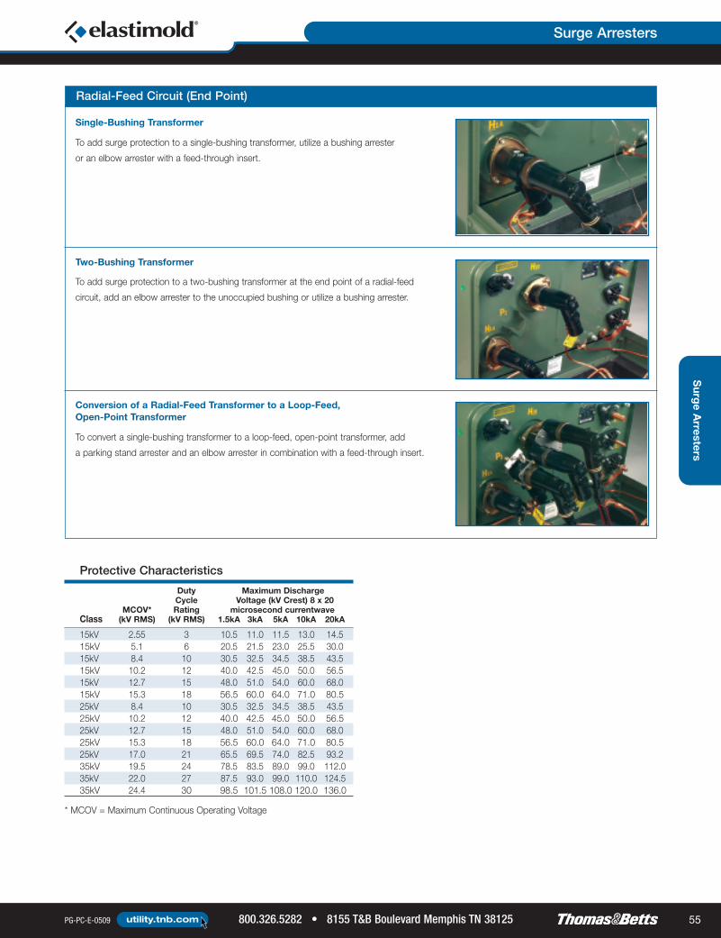
Surge Arresters
PG-PC-E-0509 800.326.5282 • 8155 T&B Boulevard Memphis TN 38125utility.tnb.com 55
Surg
eArresters
To add surge protection to a single-bushing transformer, utilize a bushing arrester
or an elbow arrester with a feed-through insert.
Single-Bushing Transformer
To add surge protection to a two-bushing transformer at the end point of a radial-feed
circuit, add an elbow arrester to the unoccupied bushing or utilize a bushing arrester.
To convert a single-bushing transformer to a loop-feed, open-point transformer, add
a parking stand arrester and an elbow arrester in combination with a feed-through insert.
Two-Bushing Transformer
Conversion of a Radial-Feed Transformer to a Loop-Feed,Open-Point Transformer
Radial-Feed Circuit (End Point)
* MCOV = Maximum Continuous Operating Voltage
Duty Maximum DischargeCycle Voltage (kV Crest) 8 x 20
MCOV* Rating microsecond currentwaveClass (kV RMS) (kV RMS) 1.5kA 3kA 5kA 10kA 20kA
15kV 2.55 3 10.5 11.0 11.5 13.0 14.515kV 5.1 6 20.5 21.5 23.0 25.5 30.015kV 8.4 10 30.5 32.5 34.5 38.5 43.515kV 10.2 12 40.0 42.5 45.0 50.0 56.515kV 12.7 15 48.0 51.0 54.0 60.0 68.015kV 15.3 18 56.5 60.0 64.0 71.0 80.525kV 8.4 10 30.5 32.5 34.5 38.5 43.525kV 10.2 12 40.0 42.5 45.0 50.0 56.525kV 12.7 15 48.0 51.0 54.0 60.0 68.025kV 15.3 18 56.5 60.0 64.0 71.0 80.525kV 17.0 21 65.5 69.5 74.0 82.5 93.235kV 19.5 24 78.5 83.5 89.0 99.0 112.035kV 22.0 27 87.5 93.0 99.0 110.0 124.535kV 24.4 30 98.5 101.5 108.0 120.0 136.0
Protective Characteristics

Surge Arresters
8155 T&B Boulevard Memphis TN 38125 • 800.326.5282 PG-PC-E-0509utility.tnb.com56
Sur
ge
Arr
este
rs
Arrester Application Table
System Line-to-LineVoltage kVrms MCOV* kV RMS
SolidlyGrounded 3-Wire
Neutral UngroundedNominal Maximum Circuits Circuits2.40 2.54 2.55 2.55
15kV 4.16 4.40 2.55 5.10Class 4.80 5.08 5.10 5.10
6.90 7.26 5.10 8.408.32 8.80 5.10 8.4012.47 13.20 8.40 15.3013.20 13.97 8.40 15.3013.80 14.50 8.40** 15.3013.80 14.50 10.20 15.306.90 7.26 5.10 8.408.32 8.80 5.10 8.4012.47 13.20 8.40 15.3013.20 13.97 8.40 15.3013.80 14.50 8.40** 15.30
25kV 13.80 14.50 10.20 15.30Class 20.78 22.00 12.70 —
20.78 22.00 15.30** —23.00 24.34 15.30 —24.94 26.40 15.30 —24.94 26.40 17.00** —28.00 29.80 17.00 —
To specify and order an MOV Surge Arrester:
1) Determine the appropriate Maximum Continuous Operating Voltage (MCOV) for your system voltage using the Arrester Application Table below.
2) Specify the appropriate Elastimold® catalog number from the Selection Chart.
for MOV Surge ArrestersOrdering Information
* MCOV = Maximum Continuous Operating Voltage.** Preferred arrester MCOV for this system voltage.
Selection Chart
Voltage MCOVDescription Class CAT. NO. kV RMS
15kV 167BSA-3 2.5515kV 167BSA-6 5.10
BSA Bushing 15kV 167BSA-10 8.40Surge Arrester 15kV 167BSA-12 10.20(includes 15kV 167BSA-15 12.70
assembly tool) 15kV 167BSA-18 15.3025kV 273BSA-10 8.40
See Notes 25kV 273BSA-12 10.201–4 25kV 273BSA-15 12.70
25kV 273BSA-18 15.3025kV 273BSA-21 17.0015kV 167ESA-3 2.5515kV 167ESA-6 5.1015kV 167ESA-10 8.40
ESA Elbow 15kV 167ESA-12 10.20Surge Arrester 15kV 167ESA-15 12.70
15kV 167ESA-18 15.30See Notes 25kV 273ESA-10 8.401, 2, 5 25kV 273ESA-12 10.20
25kV 273ESA-15 12.7025kV 273ESA-18 15.3025kV 273ESA-21 17.0015kV 167PSA-3 2.5515kV 167PSA-6 5.1015kV 167PSA-10 8.4015kV 167PSA-12 10.20
PSA Parking 15kV 167PSA-15 12.70Stand Arrester 15kV 167PSA-18 15.30
25kV 273PSA-10 8.40See Notes 25kV 273PSA-12 10.20
1–3 25kV 273PSA-15 12.7025kV 273PSA-18 15.3025kV 273PSA-21 17.00
Picture
NOTE: 1. Elastimold® PSA and BSA Arresters are equipped with a fully rated 200A switchingand fault-close loadbreak bushing.
2. Elastimold® Arresters use high-strength, silver epoxy-bonded MOV blocks and shuntedspring connections for the best circuit connection.
3. A 36" 4 AWG ground lead is provided with each unit.4. BSA installed by turning internal hex bolt (accessed through the 200A bushing interface)with a 5⁄16" hex wrench and bent-wire torque wrench supplied with each unit.
5. For 15kV and 25kV class deadbreak system Elbow Arresters, use catalog number156ESA with the appropriate duty cycle rating.

Surge Arresters
PG-PC-E-0509 800.326.5282 • 8155 T&B Boulevard Memphis TN 38125utility.tnb.com 57
Surg
eA
rresters
To specify and order an MOV Surge Arrester:
1) Determine the appropriate Maximum Continuous Operating Voltage (MCOV) for your system voltage using the Arrester Application Table below.
2) Specify the appropriate Elastimold® catalog number from the Selection Chart.
NOTE: 1. Elastimold® PSA and BSA Arresters are equipped with a fully rated 200A switchingand fault-close loadbreak bushing.
2. Elastimold® Arresters use high-strength, silver epoxy-bonded MOV blocks andshunted spring connections for the best circuit connection.
3. A 36" 4 AWG ground lead is provided with each unit.4. BSA installed by turning internal hex bolt (accessed through the 200A bushinginterface) with a 5⁄16" hex wrench and bent-wire torque wrench supplied with each unit.
5. For 15kV and 25kV class deadbreak system Elbow Arresters, use catalog number156ESA with the appropriate duty cycle rating.
for MOV Surge ArrestersOrdering Information
Arrester Application Table
System Line-to-LineVoltage kVrms MCOV* kV RMS
SolidlyGrounded 3-Wire
35kVNeutral Ungrounded
ClassNominal Maximum Circuits Circuits23.00 24.34 — 22.0034.50 36.51 22.00** —34.50 36.51 24.40 —
* MCOV = Maximum Continuous Operating Voltage.** Preferred arrester MCOV for this system voltage.
Selection Chart
Voltage MCOVDescription Class CAT. NO. kV RMS
35kV 375BSA-24 19.5035kV 375BSA-27 22.0035kV 375BSA-30 24.40
BSA BushingSurge Arrester
See Notes1–4
35kV 375ESA-24 19.5035kV 375ESA-27 22.0035kV 375ESA-30 24.40
ESA ElbowSurge Arrester
See Notes2–3
35kV 375PSA-24 19.5035kV 375PSA-27 22.0035kV 375PSA-30 24.40
PSA ParkingStand Arrester
See Notes1–3
Picture

Notes
8155 T&B Boulevard Memphis TN 38125 • 800.326.5282 PG-PC-E-0509utility.tnb.com58

Notes
PG-PC-E-0509 800.326.5282 • 8155 T&B Boulevard Memphis TN 38125utility.tnb.com 59

Notes
8155 T&B Boulevard Memphis TN 38125 • 800.326.5282 PG-PC-E-0509utility.tnb.com60


Thomas & Betts CorporationUtility Group8155 T&B Blvd.Memphis, TN 38125P: 800.326.5282F: 800.888.0690
©2009 Thomas & Betts Corporation. All rights reserved. Printed in the USA. 05/09/7.5M PG-PC-E-0509
utility.tnb.com