Elastimold - Cable Connectors, Joints, Terminations Catalogue
60
Elastimold ® Underground Cable Accessories In this section... Elastimold ® Underground Cable Accessories Overview ........................................................................... H-2–H-3 200-Amp Loadbreak Elbows .............................................. H-4–H-7 200-Amp Deadbreak Elbows ............................................. H-8–H-9 600-Amp Elbow Connectors .......................................... H-10–H-17 ComboT Integral Separable Connectors ......................... H-18–H-22 600-Amp Separable Cable Joints ................................... H-23–H-24 Multi-Point Junctions ..................................................... H-25–H-26 Permanent Distribution Cable Joints .............................. H-27–H-28 Distribution Shrink-Fit Terminations ............................... H-29–H-35 Pre-Molded Terminations......................................................... H-36 Cable Shield Adapters and Jacket Seals......................... H-37–H-38 Equipment Bushings ................................................................ H-39 Medium-Voltage Cable Accessories Technical Information .................................................... H-40–H-45 Shielded Surge Arresters ............................................... H-46–H-52 Transmission Cable Joints ............................................. H-53–H-56 Transmission Cable Terminations .................................. H-57–H-58 Transmission Cable Accessories Installation Tools ................... H-59 Transmission Cable Accessories Technical Information ............ H-60
-
Upload
thorne-derrick-power-products-tel-00-44-191-4901547 -
Category
Technology
-
view
3.014 -
download
22
description
Underground Cable Accessories Elastimold® offers the industry's most complete package for managing underground cable connections. Broad Product Range.. Elastimold accessories, available from 5kV to 138kV, connect, ground, splice, terminate and protect underground cable. Elastimold Innovation Elastimold’s long, innovative history includes pioneering such products as extended and repair elbows, jacket seal elbows, and shrink-fit joints.
Transcript of Elastimold - Cable Connectors, Joints, Terminations Catalogue
Elastimold ® Underground Cable Accessories
In this section...
Elastimold® Underground Cable Accessories
Overview ........................................................................... H-2–H-3
200-Amp Loadbreak Elbows .............................................. H-4–H-7
200-Amp Deadbreak Elbows ............................................. H-8–H-9
600-Amp Elbow Connectors .......................................... H-10–H-17
ComboT Integral Separable Connectors ......................... H-18–H-22
600-Amp Separable Cable Joints ................................... H-23–H-24
Multi-Point Junctions ..................................................... H-25–H-26
Permanent Distribution Cable Joints .............................. H-27–H-28
Distribution Shrink-Fit Terminations ............................... H-29–H-35
Pre-Molded Terminations .........................................................H-36
Cable Shield Adapters and Jacket Seals......................... H-37–H-38
Equipment Bushings ................................................................H-39
Medium-Voltage Cable Accessories Technical Information .................................................... H-40–H-45
Shielded Surge Arresters ............................................... H-46–H-52
Transmission Cable Joints ............................................. H-53–H-56
Transmission Cable Terminations .................................. H-57–H-58
Transmission Cable Accessories Installation Tools ...................H-59
Transmission Cable Accessories Technical Information ............H-60
Pamela Kinnell
Address Stamp
www.tnb.comUnited StatesTel: 901.252.8000 800.816.7809Fax: 901.252.1354
Technical ServicesTel: 888.862.3289
H-2
Overview
Pow
er &
Hig
h Vo
ltage
— E
last
imol
d® U
nder
grou
nd C
able
Acc
esso
ries Elastimold Separable Connectors, Cable Joints, Cable Terminators and other
cable accessory products have been designed and tested per applicable portions of IEEE, ANSI and other industry standards including:
• IEEE 386™ Standard for Separable Connectors
• IEEE 404™ Standard for Cable Joints and Splices
• IEEE 48™ Standard for Cable Terminations
• IEEE 592™ Standard for Exposed Semiconducting Shields
• ANSI C119.4 Standard for Copper and Aluminum Conductor Connectors
• AEIC CS8 Standards for XLP and EPR Insulated Cables
• ICEA S-94-649-2004 and S-97-682-2000 Standard for Cables Rated 5,000 – 46,000 Volts
Cable Joints And Terminations Ratings
Refer to the pages listed below for rating information:
• PCJ™ Cable Joints, page H-27
• Cable Terminations, page H-36
Separable Connector Ratings
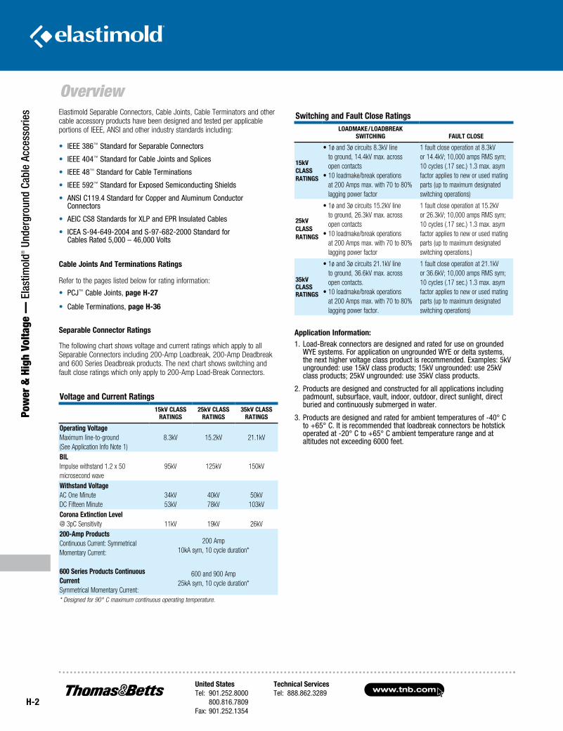
The following chart shows voltage and current ratings which apply to all Separable Connectors including 200-Amp Loadbreak, 200-Amp Deadbreak and 600 Series Deadbreak products. The next chart shows switching and fault close ratings which only apply to 200-Amp Load-Break Connectors.
Application Information: 1. Load-Break connectors are designed and rated for use on grounded
WYE systems. For application on ungrounded WYE or delta systems, the next higher voltage class product is recommended. Examples: 5kV ungrounded: use 15kV class products; 15kV ungrounded: use 25kV class products; 25kV ungrounded: use 35kV class products.
2. Products are designed and constructed for all applications including padmount, subsurface, vault, indoor, outdoor, direct sunlight, direct buried and continuously submerged in water.
3. Products are designed and rated for ambient temperatures of -40° C to +65° C. It is recommended that loadbreak connectors be hotstick operated at -20° C to +65° C ambient temperature range and at altitudes not exceeding 6000 feet.
Voltage and Current Ratings15kV ClASS
RATIngS25kV ClASS
RATIngS35kV ClASS
RATIngS
Operating Voltage Maximum line-to-ground (See Application Info Note 1)
8.3kV 15.2kV 21.1kV
BIl Impulse withstand 1.2 x 50 microsecond wave
95kV 125kV 150kV
Withstand Voltage AC One Minute DC Fifteen Minute
34kV 53kV
40kV 78kV
50kV 103kV
Corona Extinction level @ 3pC Sensitivity 11kV 19kV 26kV200-Amp Products Continuous Current: Symmetrical Momentary Current:
600 Series Products Continuous Current Symmetrical Momentary Current:
200 Amp10kA sym, 10 cycle duration*
600 and 900 Amp 25kA sym, 10 cycle duration*
* Designed for 90° C maximum continuous operating temperature.
Switching and Fault Close RatingslOADMAKE/lOADBREAK
SWITCHIng FAUlT ClOSE
15kV ClASS RATIngS
• 1ø and 3ø circuits 8.3kV line to ground, 14.4kV max. across open contacts
• 10 loadmake/break operations at 200 Amps max. with 70 to 80% lagging power factor
1 fault close operation at 8.3kV or 14.4kV; 10,000 amps RMS sym; 10 cycles (.17 sec.) 1.3 max. asym factor applies to new or used mating parts (up to maximum designated switching operations)
25kV ClASS RATIngS
• 1ø and 3ø circuits 15.2kV line to ground, 26.3kV max. across open contacts
• 10 loadmake/break operations at 200 Amps max. with 70 to 80% lagging power factor
1 fault close operation at 15.2kV or 26.3kV; 10,000 amps RMS sym; 10 cycles (.17 sec.) 1.3 max. asym factor applies to new or used mating parts (up to maximum designated switching operations.)
35kV ClASS RATIngS
• 1ø and 3ø circuits 21.1kV line to ground, 36.6kV max. across open contacts.
• 10 loadmake/break operations at 200 Amps max. with 70 to 80% lagging power factor.
1 fault close operation at 21.1kV or 36.6kV; 10,000 amps RMS sym; 10 cycles (.17 sec.) 1.3 max. asym factor applies to new or used mating parts (up to maximum designated switching operations)
United StatesTel: 901.252.8000 800.816.7809Fax: 901.252.1354
Technical ServicesTel: 888.862.3289www.tnb.com
H-3
Power &
High Voltage — Elastim
old® Underground Cable Accessories
Overview
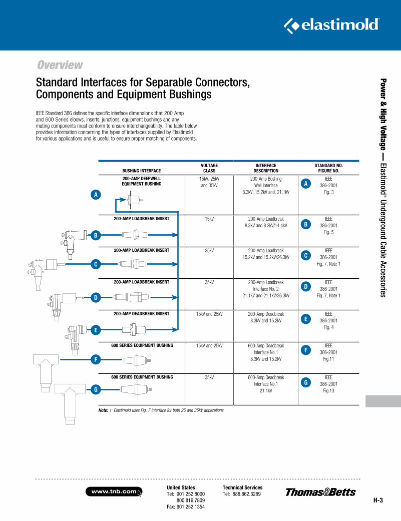
IEEE Standard 386 defines the specific interface dimensions that 200 Amp and 600 Series elbows, inserts, junctions, equipment bushings and any mating components must conform to ensure interchangeability. The table below provides information concerning the types of interfaces supplied by Elastimold for various applications and is useful to ensure proper matching of components.
Standard Interfaces for Separable Connectors, Components and Equipment Bushings
Note: 1. Elastimold uses Fig. 7 interface for both 25 and 35kV applications.
BUSHIng InTERFACEVOlTAgE
ClASSInTERFACE
DESCRIPTIOnSTAnDARD nO.
FIgURE nO.
200-AMP DEEPWEll EQUIPMEnT BUSHIng
15kV, 25kV and 35kV
200-Amp Bushing Well Interface
8.3kV, 15.2kV and, 21.1kV
IEEE386-2001
Fig. 3
200-AMP lOADBREAK InSERT 15kV 200-Amp Loadbreak 8.3kV and 8.3kV/14.4kV
IEEE386-2001
Fig. 5
200-AMP lOADBREAK InSERT 25kV 200-Amp Loadbreak 15.2kV and 15.2kV/26.3kV
IEEE 386-2001
Fig. 7, Note 1
200-AMP lOADBREAK InSERT 35kV 200-Amp Loadbreak Interface No. 2
21.1kV and 21.1kV/36.3kV
IEEE386-2001
Fig. 7, Note 1
200-AMP DEADBREAK InSERT 15kV and 25kV 200-Amp Deadbreak 8.3kV and 15.2kV
IEEE386-2001
Fig. 4
600 SERIES EQUIPMEnT BUSHIng 15kV and 25kV 600-Amp Deadbreak Interface No.1
8.3kV and 15.2kV
IEEE386-2001
Fig.11
600 SERIES EQUIPMEnT BUSHIng 35kV 600-Amp Deadbreak Interface No.1
21.1kV
IEEE386-2001
Fig.13
A
C
D
E
F
g
B
A
C
D
E
F
g
B
www.tnb.comUnited StatesTel: 901.252.8000 800.816.7809Fax: 901.252.1354
Technical ServicesTel: 888.862.3289
H-4
200-Amp Loadbreak Elbows
Pow
er &
Hig
h Vo
ltage
— E
last
imol
d® U
nder
grou
nd C
able
Acc
esso
ries 200-Amp Loadbreak
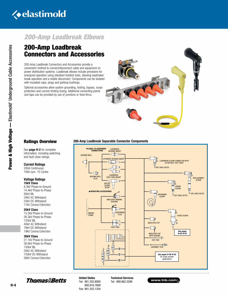
Connectors and Accessories200-Amp Loadbreak Connectors and Accessories provide a convenient method to connect/disconnect cable and equipment on power distribution systems. Loadbreak elbows include provisions for energized operation using standard hotstick tools, allowing loadmake/break operation and a visible disconnect. Components can be isolated with insulated caps, plugs and parking bushings.
Optional accessories allow system grounding, testing, bypass, surge protection and current limiting fusing. Additional connecting points and taps can be provided by use of junctions or feed-thrus.
Ratings Overview
See page H-2 for complete information, including switching and fault close ratings.
Current Ratings 200A Continuous 10kA sym. 10 Cycles
Voltage Ratings 15kV Class 8.3kV Phase-to-Ground 14.4kV Phase-to-Phase 95kV BIL 34kV AC Withstand 53kV DC Withstand 11kV Corona Extinction
25kV Class 15.2kV Phase-to-Ground 26.3kV Phase-to-Phase 125kV BIL 40kV AC Withstand 78kV DC Withstand 19kV Corona Extinction
35kV Class 21.1kV Phase-to-Ground 36.6kV Phase-to-Phase 150kV BIL 50kV AC Withstand 103kV DC Withstand 26kV Corona Extinction
200-Amp Loadbreak Separable Connector Components
See pages H-63–H-67
CABLE TO EQUIPMENT CONNECTIONS
OPERATING ACCESSORIES
BUSHING WELL PLUG
BUSHING WELL
LOADBREAK BUSHING INSERT
EXTENDED BUSHING INSERT
LOADBREAK FEED-THRU INSERT
BOLTED ELBOWW/TAP
INSULATED PARKING BUSHING
GROUNDING PLUG
PARKING STAND
FEED THRU
See pages H-46–H-52 for surge arrester
applications
LOADBREAK ELBOW CONNECTOR WITH OR WITHOUT TEST POINT
SEE CABLE NOTES
SEE CABLE NOTESSEE CABLE NOTESGROUNDING
ELBOW
REPAIR ELBOW
REPLACEMENT ELBOW
FUSED ELBOW
INSULATED CAP
INSULATED CAP WITH GROUND
TEST ROD
ASSEMBLY TOOL
United StatesTel: 901.252.8000 800.816.7809Fax: 901.252.1354
Technical ServicesTel: 888.862.3289www.tnb.com
H-5
Power &
High Voltage — Elastim
old® Underground Cable Accessories
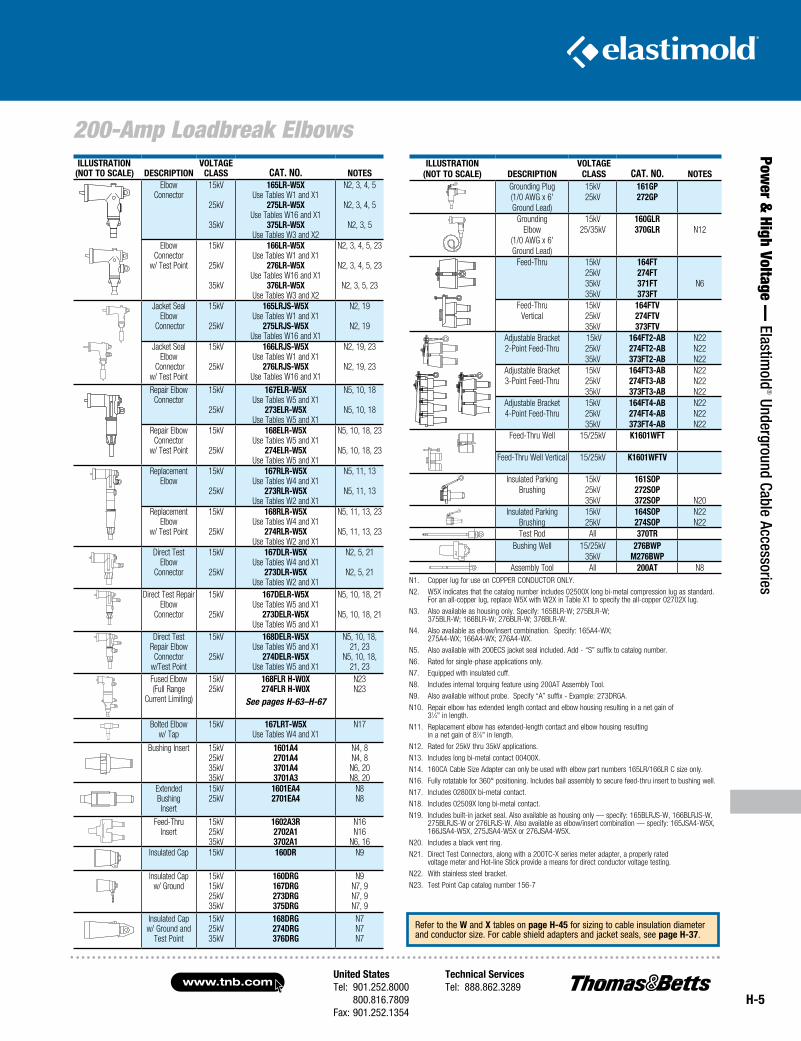
200-Amp Loadbreak ElbowsILLUSTRATION
(NOT TO SCALE) DESCRIPTION VOLTAGE
CLASS CAT. NO. NOTESGrounding Plug(1/0 AWG x 6'Ground Lead)
15kV25kV
161GP272GP
GroundingElbow
(1/0 AWG x 6'Ground Lead)
15kV25/35kV
160GLR370GLR N12
Feed-Thru 15kV25kV35kV35kV
164FT274FT371FT373FT
N6
Feed-ThruVertical
15kV25kV35kV
164FTV274FTV373FTV
Adjustable Bracket2-Point Feed-Thru
15kV25kV35kV
164FT2-AB274FT2-AB373FT2-AB
N22N22N22
Adjustable Bracket3-Point Feed-Thru
15kV 25kV35kV
164FT3-AB274FT3-AB373FT3-AB
N22N22N22
Adjustable Bracket4-Point Feed-Thru
15kV 25kV35kV
164FT4-AB274FT4-AB373FT4-AB
N22N22N22
Feed-Thru Well 15/25kV K1601WFT
Feed-Thru Well Vertical 15/25kV K1601WFTV
Insulated Parking Brushing
15kV25kV35kV
161SOP272SOP372SOP N20
Insulated Parking Brushing
15kV25kV
164SOP274SOP
N22 N22
Test Rod All 370TRBushing Well 15/25kV
35kV276BWP
M276BWP
Assembly Tool All 200AT N8
ILLUSTRATION(NOT TO SCALE) DESCRIPTION
VOLTAGECLASS CAT. NO. NOTES
ElbowConnector
15kV
25kV
35kV
165LR-W5XUse Tables W1 and X1
275LR-W5XUse Tables W16 and X1
375LR-W5XUse Tables W3 and X2
N2, 3, 4, 5
N2, 3, 4, 5
N2, 3, 5
ElbowConnector
w/ Test Point
15kV
25kV
35kV
166LR-W5XUse Tables W1 and X1
276LR-W5XUse Tables W16 and X1
376LR-W5XUse Tables W3 and X2
N2, 3, 4, 5, 23
N2, 3, 4, 5, 23
N2, 3, 5, 23
Jacket SealElbow
Connector
15kV
25kV
165LRJS-W5XUse Tables W1 and X1
275LRJS-W5XUse Tables W16 and X1
N2, 19
N2, 19
Jacket SealElbow
Connectorw/ Test Point
15kV
25kV
166LRJS-W5XUse Tables W1 and X1
276LRJS-W5XUse Tables W16 and X1
N2, 19, 23
N2, 19, 23
Repair ElbowConnector
15kV
25kV
167ELR-W5XUse Tables W5 and X1
273ELR-W5XUse Tables W5 and X1
N5, 10, 18
N5, 10, 18
Repair ElbowConnector
w/ Test Point
15kV
25kV
168ELR-W5XUse Tables W5 and X1
274ELR-W5XUse Tables W5 and X1
N5, 10, 18, 23
N5, 10, 18, 23
ReplacementElbow
15kV
25kV
167RLR-W5XUse Tables W4 and X1
273RLR-W5XUse Tables W2 and X1
N5, 11, 13
N5, 11, 13
ReplacementElbow
w/ Test Point
15kV
25kV
168RLR-W5XUse Tables W4 and X1
274RLR-W5XUse Tables W2 and X1
N5, 11, 13, 23
N5, 11, 13, 23
Direct TestElbow
Connector
15kV
25kV
167DLR-W5XUse Tables W4 and X1
273DLR-W5XUse Tables W2 and X1
N2, 5, 21
N2, 5, 21
Direct Test Repair Elbow
Connector
15kV
25kV
167DELR-W5XUse Tables W5 and X1
273DELR-W5XUse Tables W5 and X1
N5, 10, 18, 21
N5, 10, 18, 21
Direct TestRepair Elbow
Connectorw/Test Point
15kV
25kV
168DELR-W5XUse Tables W5 and X1
274DELR-W5XUse Tables W5 and X1
N5, 10, 18, 21, 23
N5, 10, 18, 21, 23
Fused Elbow(Full Range
Current Limiting)
15kV25kV
168FLR H-W0X274FLR H-W0X
See pages H-63–H-67
N23N23
Bolted Elboww/ Tap
15kV 167LRT-W5XUse Tables W4 and X1
N17
Bushing Insert 15kV25kV35kV35kV
1601A42701A43701A43701A3
N4, 8N4, 8N6, 20N8, 20
ExtendedBushingInsert
15kV25kV
1601EA42701EA4
N8N8
Feed-ThruInsert
15kV25kV35kV
1602A3R2702A13702A1
N16N16
N6, 16Insulated Cap 15kV 160DR N9
Insulated Capw/ Ground
15kV15kV25kV35kV
160DRG167DRG273DRG375DRG
N9N7, 9N7, 9N7, 9
Insulated Capw/ Ground and
Test Point
15kV25kV35kV
168DRG274DRG376DRG
N7N7N7
Refer to the W and X tables on page H-45 for sizing to cable insulation diameter and conductor size. For cable shield adapters and jacket seals, see page H-37.
N1. Copper lug for use on COPPER CONDUCTOR ONLY.
N2. W5X indicates that the catalog number includes 02500X long bi-metal compression lug as standard. For an all-copper lug, replace W5X with W2X in Table X1 to specify the all-copper 02702X lug.
N3. Also available as housing only. Specify: 165BLR-W; 275BLR-W; 375BLR-W; 166BLR-W; 276BLR-W; 376BLR-W.
N4. Also available as elbow/insert combination. Specify: 165A4-WX; 275A4-WX; 166A4-WX; 276A4-WX.
N5. Also available with 200ECS jacket seal included. Add - “S” suffix to catalog number.
N6. Rated for single-phase applications only.
N7. Equipped with insulated cuff.
N8. Includes internal torquing feature using 200AT Assembly Tool.
N9. Also available without probe. Specify “A” suffix - Example: 273DRGA.
N10. Repair elbow has extended length contact and elbow housing resulting in a net gain of 31⁄4" in length.
N11. Replacement elbow has extended-length contact and elbow housing resulting in a net gain of 87⁄8" in length.
N12. Rated for 25kV thru 35kV applications.
N13. Includes long bi-metal contact 00400X.
N14. 160CA Cable Size Adapter can only be used with elbow part numbers 165LR/166LR C size only.
N16. Fully rotatable for 360° positioning. Includes bail assembly to secure feed-thru insert to bushing well.
N17. Includes 02800X bi-metal contact.
N18. Includes 02509X long bi-metal contact.
N19. Includes built-in jacket seal. Also available as housing only — specify: 165BLRJS-W, 166BLRJS-W, 275BLRJS-W or 276LRJS-W. Also available as elbow/insert combination — specify: 165JSA4-W5X, 166JSA4-W5X, 275JSA4-W5X or 276JSA4-W5X.
N20. Includes a black vent ring.
N21. Direct Test Connectors, along with a 200TC-X series meter adapter, a properly rated voltage meter and Hot-line Stick provide a means for direct conductor voltage testing.
N22. With stainless steel bracket.
N23. Test Point Cap catalog number 156-7
www.tnb.comUnited StatesTel: 901.252.8000 800.816.7809Fax: 901.252.1354
Technical ServicesTel: 888.862.3289
H-6
200-Amp Loadbreak Elbows
Pow
er &
Hig
h Vo
ltage
— E
last
imol
d® U
nder
grou
nd C
able
Acc
esso
ries
Ratings Overview
See page H-2 for complete information, including switching and fault close ratings.
Current Ratings 200A Continuous 10kA sym. 10 Cycles
Voltage Ratings 15kV Class 8.3kV Phase-to-Ground 14.4kV Phase-to-Phase 95kV BIL 34kV AC Withstand 53kV DC Withstand 11kV Corona Extinction
25kV Class 15.2kV Phase-to-Ground 26.3kV Phase-to-Phase 125kV BIL 40kV AC Withstand 78kV DC Withstand 19kV Corona Extinction
35kV Class 21.1kV Phase-to-Ground 36.6kV Phase-to-Phase 150kV BIL 50kV AC Withstand 103kV DC Withstand 26kV Corona Extinction
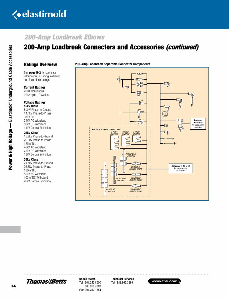
200-Amp Loadbreak Connectors and Accessories (continued)
200-Amp Loadbreak Separable Connector Components
See pages H-63–H-67
for fused elbow selection
See pages H-46–H-52 for surge arrester
applications
CABLE TO CABLE CONNECTIONS4-POINT
JUNCTION3-POINT
JUNCTION2-POINT
JUNCTION
2 POINT WELL JUNCTION
3-POINT WELL JUNCTION
4-POINT WELL JUNCTION
LOADBREAK BUSHING INSERT
LOADBREAK BUSHING INSERT
LOADBREAK BUSHING INSERT
United StatesTel: 901.252.8000 800.816.7809Fax: 901.252.1354
Technical ServicesTel: 888.862.3289www.tnb.com
H-7
Power &
High Voltage — Elastim
old® Underground Cable Accessories
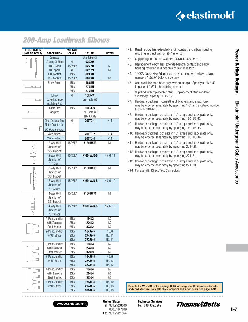
200-Amp Loadbreak ElbowsILLuSTRATION
(NOT TO SCALE) DESCRIpTION VOLTAgE
CLASS CAT. NO. NOTES
Contacts:LR Long Bi-Metal
ELR Bi-MetalLR Copper
LRT ContactRLR Contact
All15/25kV
All15kV
15/25kV
Use Table X102500X02509X02702X02800X00400X
N1N2
N3Elbow Probe 15kV
25kV35kV
166LRF274LRF375LRF
ElbowCable EntranceInsulating Plug
All 10Ep-WUse Table W6
Cable SizeAdapter
15kV 160CA-WUse Table W6EB-FA Only
N4
Direct Voltage TestMeter Adapter for:
HD Electric Meters
All 200TC-1 N14
Ross Meters 200TC-2 N14Chance Meters 200TC-4 N14
2-Way WellJunction w/S.S. Bracket
15/25kV K1601WJ2 N6
2-Way WellJunction w/“U” Straps
15/25kV K1601WJ2-5 N5, 6, 11
3-Way WellJunction w/S.S. Bracket
15/25kV K1601WJ3 N6
3-Way WellJunction w/“U” Straps
15/25kV K1601WJ3-5 N5, 6, 12
4-Way WellJunction w/S.S. Bracket
15/25kV K1601WJ4 N6
4-Way WellJunction w/“U” Straps
15/25kV K1601WJ4-5 N5, 6, 13
2-Point Junctionwith/StainlessSteel Bracket
15kV25kV35kV
164J2274J2373J2
N7N7N7
2-Point Junctionw/“U” Straps
15kV25kV35kV
164J2-5274J2-5373J2-5
N5, 8N5, 11N5, 11
3-Point Junctionwith StainlessSteel Bracket
15kV25kV35kV
164J3274J3373J3
N7N7N7
3-Point Junctionw/“U” Straps
15kV25kV35kV
164J3-5274J3-5373J3-5
N5, 9N5, 12N5, 12
4-Point Junctionwith StainlessSteel Bracket
15kV25kV35kV
164J4274J4373J4
N7N7N7
4-Point Junctionw/“U” Straps
15kV25kV35kV
164J4-5274J4-5373J4-5
N5, 10N5, 13N5, 13
N1. Repair elbow has extended-length contact and elbow housing resulting in a net gain of 31⁄4" in length.
N2. Copper lug for use on COPPER CONDUCTOR ONLY.
N3. Replacement elbow has extended-length contact and elbow housing resulting in a net gain of 87⁄8" in length.
N4. 160CA Cable Size Adapter can only be used with elbow catalog numbers 165LR/166LR C size only.
N5. Also available as rubber only, without straps. Specify suffix “-4” in place of “-5” in the catalog number.
N6. Supplied with replaceable stud. Replacement stud available separately. Specify 1000-150.
N7. Hardware packages, consisting of brackets and straps only, may be ordered separately by specifying “-6” in the catalog number. Example 164J4-6.
N8. Hardware package, consists of “U” straps and back plate only, may be ordered separately by specifying 1601US-J2.
N9. Hardware package, consists of “U” straps and back plate only, may be ordered separately by specifying 1601US-J3.
N10. Hardware package, consists of “U” straps and back plate only, may be ordered separately by specifying 1601US-J4.
N11. Hardware package, consists of “U” straps and back plate only, may be ordered separately by specifying 271-68.
N12. Hardware package, consists of “U” straps and back plate only, may be ordered separately by specifying 271-61.
N13. Hardware package, consists of “U” straps and back plate only, may be ordered separately by specifying 271-70.
N14. For use with Direct Test Connectors.
Refer to the W and X tables on page H-45 for sizing to cable insulation diameter and conductor size. For cable shield adapters and jacket seals, see page H-37.
www.tnb.comUnited StatesTel: 901.252.8000 800.816.7809Fax: 901.252.1354
Technical ServicesTel: 888.862.3289
H-8
200-Amp Deadbreak Elbows
Pow
er &
Hig
h Vo
ltage
— E
last
imol
d® U
nder
grou
nd C
able
Acc
esso
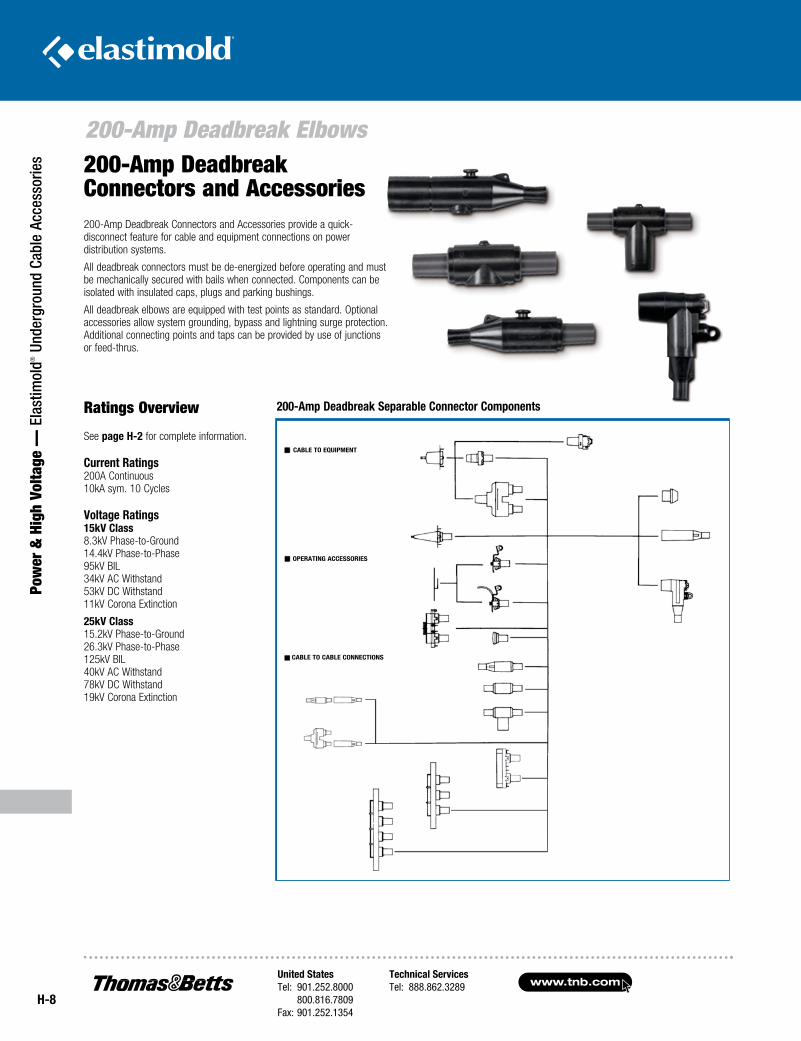
ries 200-Amp Deadbreak
Connectors and Accessories200-Amp Deadbreak Connectors and Accessories provide a quick-disconnect feature for cable and equipment connections on power distribution systems.
All deadbreak connectors must be de- energized before operating and must be mechanically secured with bails when connected. Components can be isolated with insulated caps, plugs and parking bushings.
All deadbreak elbows are equipped with test points as standard. Optional accessories allow system grounding, bypass and lightning surge protection. Additional connecting points and taps can be provided by use of junctions or feed-thrus.
Ratings Overview
See page H-2 for complete information.
Current Ratings 200A Continuous 10kA sym. 10 Cycles
Voltage Ratings 15kV Class 8.3kV Phase-to-Ground 14.4kV Phase-to-Phase 95kV BIL 34kV AC Withstand 53kV DC Withstand 11kV Corona Extinction
25kV Class 15.2kV Phase-to-Ground 26.3kV Phase-to-Phase 125kV BIL 40kV AC Withstand 78kV DC Withstand 19kV Corona Extinction
200-Amp Deadbreak Separable Connector Components
Except for locking splices all 200A deadbreak products must be mechanically secured with a
bail when connected
See pages H-46–H-52 for surge arresters applications
LOCKING AND REPAIR SPLICE
LOCKING “Y” SPLICE
FEED THRU
PARKING STAND
STAND-OFF PLUG
INTEGRAL BUSHING
GROUNDING PLUG
INSULATED PLUG
STRAIGHT PLUG
IN-LINE JUNCTION
TEE SPLICE
BUSHING WELL
BUSHING INSERT
BUSHING WELL PLUG
DEADBREAK FEED-THRU INSERT
INSULATED CAP
STRAIGHT RECEPTACLE
ELBOW CONNECTOR
3-POINT JUNCTION
4-POINT JUNCTION
2-POINT JUNCTION
CABLE TO EQUIPMENT
OPERATING ACCESSORIES
CABLE TO CABLE CONNECTIONS
United StatesTel: 901.252.8000 800.816.7809Fax: 901.252.1354
Technical ServicesTel: 888.862.3289www.tnb.com
H-9
Power &
High Voltage — Elastim
old® Underground Cable Accessories
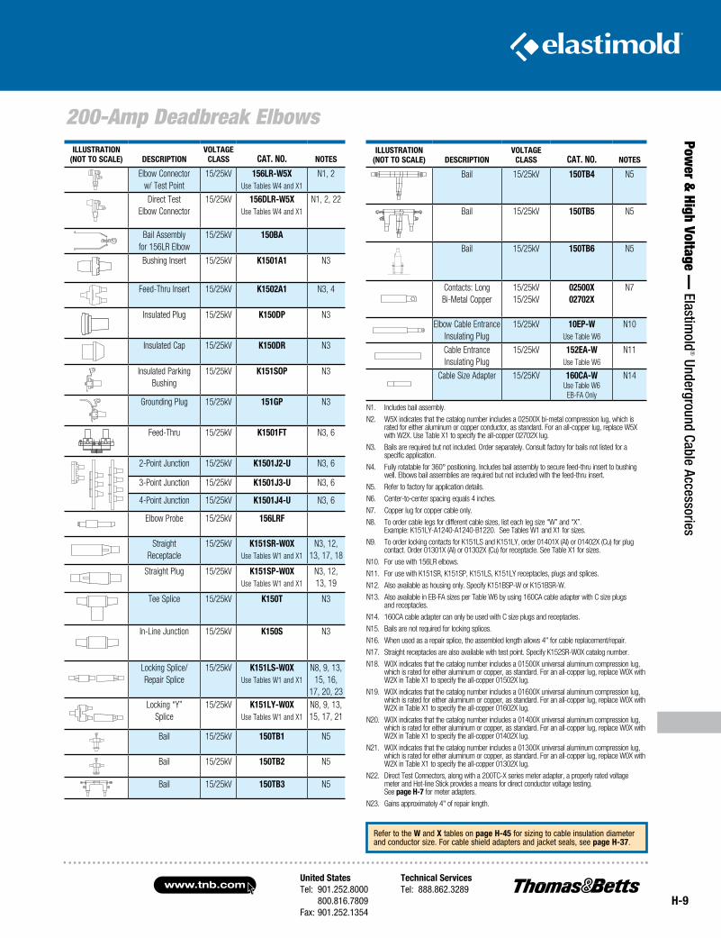
200-Amp Deadbreak ElbowsILLUSTRATION
(NOT TO SCALE) DESCRIPTIONVOLTAGE
CLASS CAT. NO. NOTES
Bail 15/25kV 150TB4 N5
Bail 15/25kV 150TB5 N5
Bail 15/25kV 150TB6 N5
Contacts: Long Bi-Metal Copper
15/25kV 15/25kV
02500X 02702X
N7
Elbow Cable Entrance Insulating Plug
15/25kV 10EP-WUse Table W6
N10
Cable Entrance Insulating Plug
15/25kV 152EA-WUse Table W6
N11
Cable Size Adapter 15/25KV 160CA-WUse Table W6EB-FA Only
N14
ILLUSTRATION(NOT TO SCALE) DESCRIPTION
VOLTAGECLASS CAT. NO. NOTES
Elbow Connectorw/ Test Point
15/25kV 156LR-W5XUse Tables W4 and X1
N1, 2
Direct TestElbow Connector
15/25kV 156DLR-W5XUse Tables W4 and X1
N1, 2, 22
Bail Assemblyfor 156LR Elbow
15/25kV 150BA
Bushing Insert 15/25kV K1501A1 N3
Feed-Thru Insert 15/25kV K1502A1 N3, 4
Insulated Plug 15/25kV K150DP N3
Insulated Cap 15/25kV K150DR N3
Insulated ParkingBushing
15/25kV K151SOP N3
Grounding Plug 15/25kV 151GP N3
Feed-Thru 15/25kV K1501FT N3, 6
2-Point Junction 15/25kV K1501J2-U N3, 6
3-Point Junction 15/25kV K1501J3-U N3, 6
4-Point Junction 15/25kV K1501J4-U N3, 6
Elbow Probe 15/25kV 156LRF
StraightReceptacle
15/25kV K151SR-W0XUse Tables W1 and X1
N3, 12, 13, 17, 18
Straight Plug 15/25kV K151SP-W0XUse Tables W1 and X1
N3, 12, 13, 19
Tee Splice 15/25kV K150T N3
In-Line Junction 15/25kV K150S N3
Locking Splice/Repair Splice
15/25kV K151LS-W0XUse Tables W1 and X1
N8, 9, 13, 15, 16,
17, 20, 23Locking “Y”
Splice15/25kV K151LY-W0X
Use Tables W1 and X1
N8, 9, 13, 15, 17, 21
Bail 15/25kV 150TB1 N5
Bail 15/25kV 150TB2 N5
Bail 15/25kV 150TB3 N5
N1. Includes bail assembly.
N2. W5X indicates that the catalog number includes a 02500X bi-metal compression lug, which is rated for either aluminum or copper conductor, as standard. For an all-copper lug, replace W5X with W2X. Use Table X1 to specify the all-copper 02702X lug.
N3. Bails are required but not included. Order separately. Consult factory for bails not listed for a specific application.
N4. Fully rotatable for 360° positioning. Includes bail assembly to secure feed-thru insert to bushing well. Elbows bail assemblies are required but not included with the feed-thru insert.
N5. Refer to factory for application details.
N6. Center-to-center spacing equals 4 inches.
N7. Copper lug for copper cable only.
N8. To order cable legs for different cable sizes, list each leg size “W” and “X”. Example: K151LY-A1240-A1240-B1220. See Tables W1 and X1 for sizes.
N9. To order locking contacts for K151LS and K151LY, order 01401X (Al) or 01402X (Cu) for plug contact. Order 01301X (Al) or 01302X (Cu) for receptacle. See Table X1 for sizes.
N10. For use with 156LR elbows.
N11. For use with K151SR, K151SP, K151LS, K151LY receptacles, plugs and splices.
N12. Also available as housing only. Specify K151BSP-W or K151BSR-W.
N13. Also available in EB-FA sizes per Table W6 by using 160CA cable adapter with C size plugs and receptacles.
N14. 160CA cable adapter can only be used with C size plugs and receptacles.
N15. Bails are not required for locking splices.
N16. When used as a repair splice, the assembled length allows 4" for cable replacement/repair.
N17. Straight receptacles are also available with test point. Specify K152SR-W0X catalog number.
N18. W0X indicates that the catalog number includes a 01500X universal aluminum compression lug, which is rated for either aluminum or copper, as standard. For an all-copper lug, replace W0X with W2X in Table X1 to specify the all-copper 01502X lug.
N19. W0X indicates that the catalog number includes a 01600X universal aluminum compression lug, which is rated for either aluminum or copper, as standard. For an all-copper lug, replace W0X with W2X in Table X1 to specify the all-copper 01602X lug.
N20. W0X indicates that the catalog number includes a 01400X universal aluminum compression lug, which is rated for either aluminum or copper, as standard. For an all-copper lug, replace W0X with W2X in Table X1 to specify the all-copper 01402X lug.
N21. W0X indicates that the catalog number includes a 01300X universal aluminum compression lug, which is rated for either aluminum or copper, as standard. For an all-copper lug, replace W0X with W2X in Table X1 to specify the all-copper 01302X lug.
N22. Direct Test Connectors, along with a 200TC-X series meter adapter, a properly rated voltage meter and Hot-line Stick provides a means for direct conductor voltage testing. See page H-7 for meter adapters.
N23. Gains approximately 4" of repair length.
Refer to the W and X tables on page H-45 for sizing to cable insulation diameter and conductor size. For cable shield adapters and jacket seals, see page H-37.
www.tnb.comUnited StatesTel: 901.252.8000 800.816.7809Fax: 901.252.1354
Technical ServicesTel: 888.862.3289
H-10
600-Amp Elbow Connectors
Pow
er &
Hig
h Vo
ltage
— E
last
imol
d® U
nder
grou
nd C
able
Acc
esso
ries
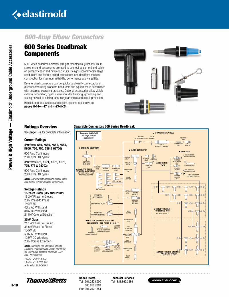
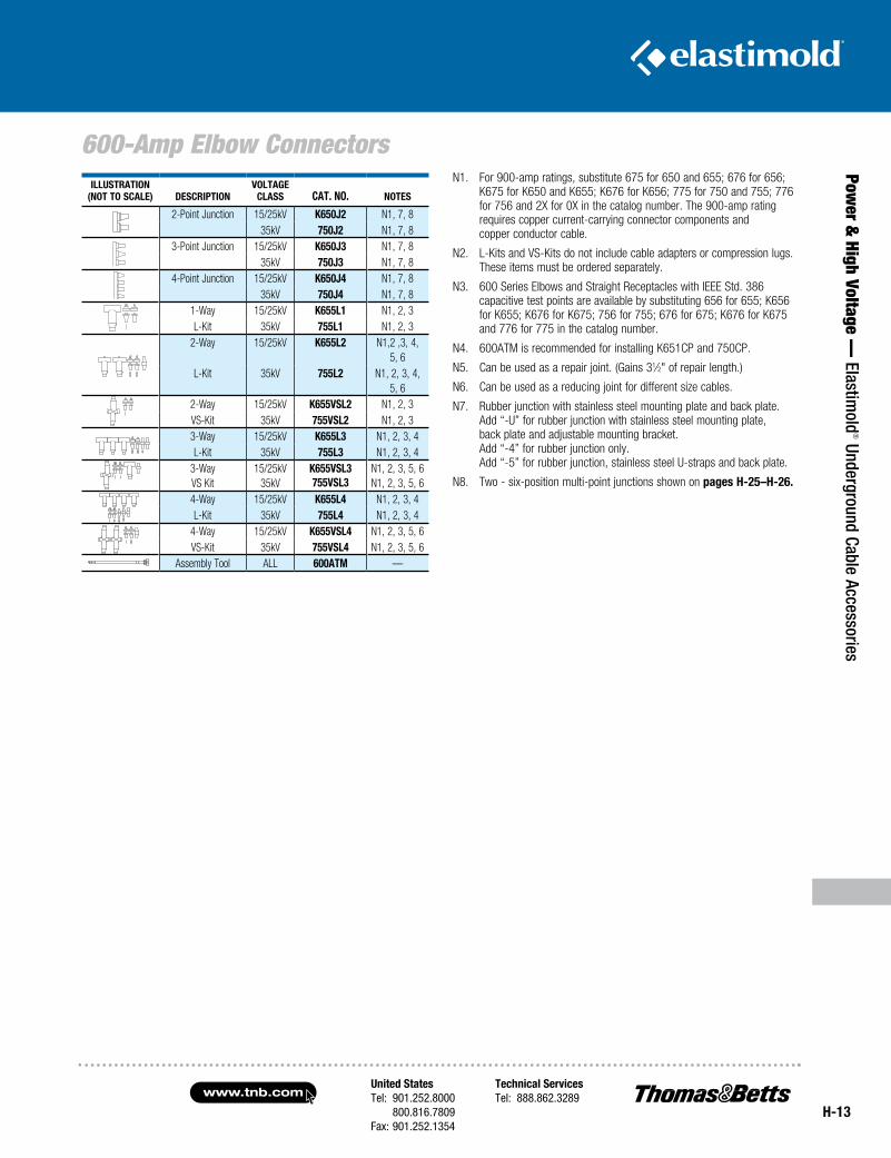
600 Series deadbreak elbows, straight receptacles, junctions, vault stretchers and accessories are used to connect equipment and cable on primary feeder and network circuits. Designs accommodate large conductors and feature bolted connections and deadfront modular construction for maximum reliability, performance and versatility.
De-energized connectors can be quickly and easily connected and disconnected using standard hand tools and equipment in accordance with accepted operating practices. Optional accessories allow visible external separation, bypass, isolation, dead-ending, grounding and testing as well as adding taps, surge arresters and circuit protection.
Hotstick-operable and separable joint systems are shown on pages H-14–H-17 and H-23–H-24.
600 Series Deadbreak Components
Ratings OverviewSee page H-2 for complete information.
Current Ratings(Prefixes: 650, K650, K651, K655, K656, 750, 755, 756 & 03700)
600 Amp Continuous 25kA sym., 10 cycles
(Prefixes 675, K671, K675, K676, 775, 776 & 03702)
900 Amp Continuous 25kA sym., 10 cyclesNote: 900-amp ratings require copper cable and copper current-carrying components.
Voltage Ratings 15/25kV Class (5kV thru 28kV) 16.2kV Phase-to-Ground 28kV Phase-to Phase 140kV BIL 45kV AC Withstand 84kV DC Withstand 21.5kV Corona Extinction
35kV Class 21.1kV Phase-to-Ground 36.6kV Phase-to-Phase 150kV BIL 50kV AC Withstand 103kV DC Withstand 26kV Corona ExtinctionNote: Elastimold has increased the IEEE Standard Prod uction and Design Test levels for 25kV Class products to include 27kV and 28kV systems.
* Tested at 8.3/14.9kV † Tested at 15.2/26.3kV • Tested at 21.1/36.6kV
See pages H-46–H-52 for surge arrester
applications
Separable Connectors 600 Series Deadbreak
†
†
*†•SEE PAGES H-16–H-17
SEE PAGES H-20–H-21 FOR ADDITIONAL JUNCTIONS
SEE PAGES H-16–H-17
HOTSTICK OPERABLE 600 SERIES CONNECTORS - SEE PAGES H-14–H-17
SEE PAGES H-14–H-15
TEST AND GROUND
CABLE TO EquIPmENT
STRAIGHT RECEPTACLE
ELBOw CONNECTOR200A TAPS
600 SERIES TAPS
CABLE TO CABLE uTILIzING L-KITSSEE PAGES H-12–H-13
CABLE TO CABLE (uTILIzING juNCTIONS)
INTEGRAL bUSHING
THREADED STUD bUSHING
ExTENDERCONNECTING
PLUG
2 PT JUNCTION
3 PT JUNCTION
4 PT JUNCTION
OPERATING ACCESSORIES
GROUNDING PLUG
INSULATED PARkING bUSHING
THREADED COmPRESSION LUG
STICk-OP LOADbREAk REDUCING TAP PLUG
STICk-OP
CAm-OP RETAINER SLEEvES
CAm-OP LINk CONNECTOR
CAm-OP
CAbLE ADAPTER
COmPRESSION LUG
vAULT STRETCHER
THREADED STUD
vAULT STRETCHER CONNECTOR
COmPRESSION LUG
CAbLE ADAPTER
THREADED STUD
INSULATED CAP wITH
TEST POINT
bUSHING ExTENDER
CAbLE ADAPTER
COmPRESSION LUG
THREADED STUD
600 SERIES ELbOw
INSULATEDPLUG
vOLTAGE DETECTION
CAP
CONNECTING PLUG
STRAIGHT RECEPTACLE ADAPTER
bOLT & wASHER
STRAIGHT RECEPTACLE HOUSING
COmPRESSION LUG
CAbLE ADAPTER
RETAINING RING
200A DEADbREAk SEE PAGES H-8–H-9
200A LOADbREAk SEE PAGES H-4–H-5
SPANNER wRENCH
DEADbREAk REDUCING TAP
PLUG
REDUCING TAP wELL
LOADbREAk ELbOw TAP
PLUG
CABLE TO CABLE uTILIzING VAuLT STRETCHERS
SEE PAGES H-12–H-13
United StatesTel: 901.252.8000 800.816.7809Fax: 901.252.1354
Technical ServicesTel: 888.862.3289www.tnb.com
H-11
Power &
High Voltage — Elastim
old® Underground Cable Accessories
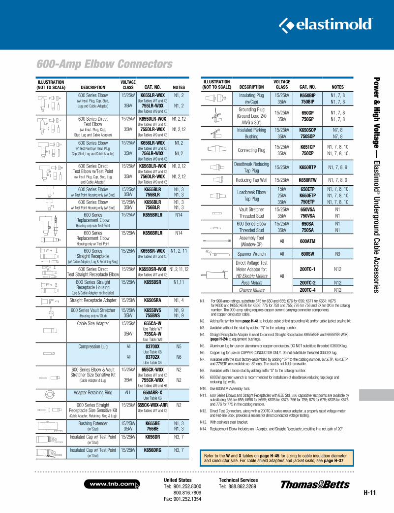
600-Amp Elbow ConnectorsILLuSTRATION
(NOT TO SCALE) DESCRIPTIONVOLTAGE
CLASS CAT. NO. NOTES
600 Series Elbow(w/ Insul. Plug, Cap, Stud, Lug and Cable Adapter)
15/25kV
35kV
K655LR-w0X Use Tables W7 and X6
755LR-w0X Use Tables W9 and X6
N1, 2
N1, 2
600 Series Direct Test Elbow
(w/ Insul. Plug, Cap, Stud Lug and Cable Adapter)
15/25kV
35kV
K655DLR-w0X Use Tables W7 and X6
755DLR-w0X Use Tables W9 and X6
N1, 2, 12
N1, 2, 12
600 Series Elbow w/ Test Point (w/ Insul. Plug,
Cap, Stud, Lug and Cable Adapter)
15/25kV
35kV
K656LR-w0XUse Tables W7 and X6
756LR-w0X Use Tables W9 and X6
N1, 2
N1, 2
600 Series DirectTest Elbow w/Test Point (w/ Insul. Plug, Cap, Stud, Lug
and Cable Adapter)
15/25kV
35kV
K656DLR-w0X Use Tables W7 and X6
756DLR-w0X Use Tables W9 and X6
N1, 2, 12
N1, 2, 12
600 Series Elboww/ Test Point Housing only (w/ Stud)
15/25kV 35kV
K655BLR755BLR
N1, 3 N1, 3
600 Series Elboww/ Test Point Housing only (w/ Stud)
15/25kV 35kV
K656BLR756BLR
N1, 3N1, 3
600 Series Replacement ElbowHousing only w/o Test Point
15/25kV K655BRLR N14
600 Series Replacement ElbowHousing only w/ Test Point
15/25kV
K656BRLR N14
600 Series Straight Receptacle
(w/ Cable Adapter, Lug & Retaining Ring)
15/25kV K655SR-w0X Use Tables W7 and X6
N1, 2, 11
600 Series DirectTest Straight Receptacle Elbow
15/25kV K655DSR-w0X Use Tables W7 and X6
N1, 2, 11, 12
600 Series Straight Receptacle Housing
(Lug & Cable Adapter not included)
15/25kV K655BSR N1,11
Straight Receptacle Adapter 15/25kV K650SRA N1, 4
600 Series Vault Stretcher(Housing only w/ Stud)
15/25kV 35kV
K655BVS755BVS
N1, 9N1, 9
Cable Size Adapter 15/25kV
35kV
655CA-w Use Table W7 755CA-w Use Table W9
Compression Lug All
All
03700X Use Table X6 03702X
Use Table X6
N5
N6
600 Series Elbow & Vault Stretcher Size Sensitive Kit
(Cable Adapter & Lug)
15/25kV
35kV
655CK-w0X Use Tables W7 and X6
755CK-w0X Use Tables W9 and X6
N2
N2
Adapter Retaining Ring ALL 650ARR-X Use Table X6
600 Series Straight Receptacle Size Sensitive Kit (Cable Adapter, Retaining Ring & Lug)
15/25kV 655CK-w0X-ARR Use Tables W7 and X6
N2
Bushing Extender (w/ Stud)
15/25kV 35kV
K655BE755BE
N1, 3 N1, 3
Insulated Cap w/ Test Point (w/ Stud)
15/25kV K656DR N3, 7
Insulated Cap w/ Test Point (w/ Stud)
15/25kV K656DRG N3, 7
ILLuSTRATION (NOT TO SCALE) DESCRIPTION
VOLTAGE CLASS CAT. NO. NOTES
Insulating Plug (w/Cap)
15/25kV 35kV
K650BIP 750BIP
N1, 7, 8 N1, 7, 8
Grounding Plug (Ground Lead 2/0
AWG x 30")
15/25kV 35kV
650GP 750GP
N1, 7, 8 N1, 7, 8
Insulated Parking Bushing
15/25kV 35kV
K650SOP 750SOP
N7, 8 N7, 8
Connecting Plug15/25kV
35kVK651CP 750CP
N1, 7, 8, 10 N1, 7, 8, 10
Deadbreak Reducing Tap Plug
15/25kV K650RTP N1, 7, 8, 9
Reducing Tap Well 15/25kV K650RTw N1, 7, 8, 9
Loadbreak Elbow Tap Plug
15kV25kV 35kV
650ETP K650ETP 750ETP
N1, 7, 8, 10 N1, 7, 8, 10 N1, 7, 8, 10
Vault Stretcher Threaded Stud
15/25kV 35kV
650VSA 750VSA
N1 N1
600 Series Elbow Threaded Stud
15/25kV 35kV
650SA 750SA
N1 N1
Assembly Tool (Window-OP)
All 600ATm
Spanner Wrench All 600Sw N9
Direct Voltage Test Meter Adapter for: HD Electric Meters All
200TC-1 N12
Ross Meters 200TC-2 N12Chance Meters 200TC-4 N12
N1. For 900-amp ratings, substitute 675 for 650 and 655; 676 for 656; K671 for K651; K675 for K650 and K655; K676 for K656; 775 for 750 and 755; 776 for 756 and 2X for 0X in the catalog number. The 900-amp rating requires copper current-carrying connector components and copper conductor cable.
N2. Add suffix symbol from page H-41 to include cable shield grounding kit and/or cable jacket sealing kit.
N3. Available without the stud by adding “N” to the catalog number.
N4. Straight Receptacle Adapter is used to connect Straight Receptacles K655YBSR and K655YSR-W0X (page H-24) to equipment bushings.
N5. Aluminum lug for use on aluminum or copper conductors. DO NOT substitute threaded 03600X lug.
N6. Copper lug for use on COPPER CONDUCTOR ONLY. Do not substitute threaded 03602X lug.
N7. Available with the stud factory-assembled by adding “SP” to the catalog number. 675ETP, K675ETP and 775ETP are available as -SP only. The stud is not field removable.
N8. Available with a loose stud by adding suffix “S” to the catalog number.
N9. 600SW spanner wrench is recommended for installation of deadbreak reducing tap plugs and reducing tap wells.
N10. Use 600ATM Assembly Tool.
N11. 600 Series Elbows and Straight Receptacles with IEEE Std. 386 capacitive test points are available by substituting 656 for 655; K656 for K655; K676 for K675; 756 for 755; 676 for 675; K676 for K675 and 776 for 775 in the catalog number.
N12. Direct Test Connectors, along with a 200TC-X series meter adapter, a properly rated voltage meter and Hot-line Stick; provides a means for direct conductor voltage testing.
N13. With stainless steel bracket.
N14. Replacement Elbow includes an I-Adapter, and Straight Receptacle, resulting in a net gain of 20".
Refer to the w and X tables on page H-45 for sizing to cable insulation diameter and conductor size. For cable shield adapters and jacket seals, see page H-37.
www.tnb.comUnited StatesTel: 901.252.8000 800.816.7809Fax: 901.252.1354
Technical ServicesTel: 888.862.3289
H-12
600-Amp Elbow Connectors
Pow
er &
Hig
h Vo
ltage
— E
last
imol
d® U
nder
grou
nd C
able
Acc
esso
ries
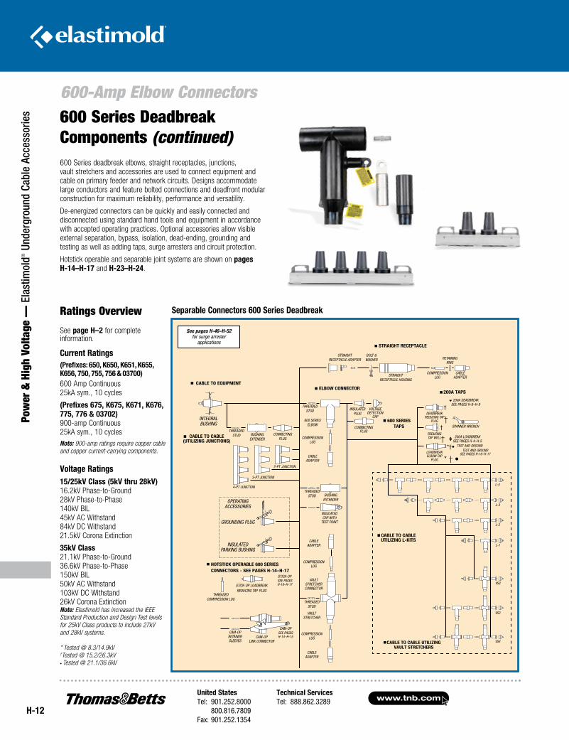
600 Series deadbreak elbows, straight receptacles, junctions, vault stretchers and accessories are used to connect equipment and cable on primary feeder and network circuits. Designs accommodate large conductors and feature bolted connections and deadfront modular construction for maximum reliability, performance and versatility.
De-energized connectors can be quickly and easily connected and disconnected using standard hand tools and equipment in accordance with accepted operating practices. Optional accessories allow visible external separation, bypass, isolation, dead-ending, grounding and testing as well as adding taps, surge arresters and circuit protection.
Hotstick operable and separable joint systems are shown on pages H-14–H-17 and H-23–H-24.
Ratings Overview
See page H–2 for complete information.
Current Ratings(Prefixes: 650, K650, K651, K655, K656, 750, 755, 756 & 03700)600 Amp Continuous25kA sym., 10 cycles
(Prefixes 675, K675, K671, K676, 775, 776 & 03702)900-amp Continuous25kA sym., 10 cyclesNote: 900-amp ratings require copper cable and copper current-carrying components.
Voltage Ratings15/25kV Class (5kV thru 28kV) 16.2kV Phase-to-Ground 28kV Phase-to-Phase 140kV BIL 45kV AC Withstand 84kV DC Withstand 21.5kV Corona Extinction
35kV Class 21.1kV Phase-to-Ground 36.6kV Phase-to-Phase 150kV BIL 50kV AC Withstand 103kV DC Withstand 26kV Corona ExtinctionNote: Elastimold has increased the IEEE Standard Prod uction and Design Test levels for 25kV Class products to include 27kV and 28kV systems.
* Tested @ 8.3/14.9kV†Tested @ 15.2/26.3kV• Tested @ 21.1/36.6kV
600 Series Deadbreak Components (continued)
Separable Connectors 600 Series Deadbreak
* † •
†
†
TEST AND GROUND
See pages H-46–H-52 for surge arrester
applications
†
†
*†•SEE PAGES H-16–H-17
SEE PAGES H-16–H-17
HOTSTICK OPERABLE 600 SERIES CONNECTORS - SEE PAGES H-14–H-17
SEE PAGES H-14–H-15
TEST AND GROUND
CABLE TO EquIPmENT
STRAIGHT RECEPTACLE
ELBOw CONNECTOR200A TAPS
600 SERIES TAPS
CABLE TO CABLE uTILIzING L-KITS
CABLE TO CABLE (uTILIzING juNCTIONS)
iNTEGRAl bUSHiNG
THREADED STUD bUSHiNG
ExTENDERcONNEcTiNG
PlUG
2-PT jUNcTiON
3-PT jUNcTiON
4-PT jUNcTiON
OPERATiNG AccESSORiES
GROUNDiNG PlUG
iNSUlATED PARkiNG bUSHiNG
THREADED cOmPRESSiON lUG
STick-OP lOADbREAk REDUciNG TAP PlUG
STick-OP
cAm-OP RETAiNER SlEEvES
cAm-OP liNk cONNEcTOR
cAm-OP
cAblE ADAPTER
cOmPRESSiON lUG
vAUlT STRETcHER
THREADED STUD
vAUlT STRETcHER cONNEcTOR
cOmPRESSiON lUG
cAblE ADAPTER
THREADED STUD
iNSUlATED cAP wiTH
TEST POiNT
bUSHiNG ExTENDER
cAblE ADAPTER
cOmPRESSiON lUG
THREADED STUD
600 SERiES ElbOw
iNSUlATEDPlUG
vOlTAGE DETEcTiON
cAP
cONNEcTiNG PlUG
STRAiGHT REcEPTAclE ADAPTER
bOlT & wASHER
STRAiGHT REcEPTAclE HOUSiNG
cOmPRESSiON lUG
cAblE ADAPTER
RETAiNiNG RiNG
200A DEADbREAk SEE PAGES H-8–H-9
200A lOADbREAk SEE PAGES H-4–H-5
SPANNER wRENcH
DEADbREAk REDUciNG TAP
PlUG
REDUciNG TAP wEll
lOADbREAk ElbOw TAP
PlUG
CABLE TO CABLE uTILIzING VAuLT STRETCHERS
l-4
l-3
l-2
l-1
vS2
vS3
vS4
United StatesTel: 901.252.8000 800.816.7809Fax: 901.252.1354
Technical ServicesTel: 888.862.3289www.tnb.com
H-13
Power &
High Voltage — Elastim
old® Underground Cable Accessories
600-Amp Elbow ConnectorsN1. For 900-amp ratings, substitute 675 for 650 and 655; 676 for 656;
K675 for K650 and K655; K676 for K656; 775 for 750 and 755; 776 for 756 and 2X for 0X in the catalog number. The 900-amp rating requires copper current-carrying connector components and copper conductor cable.
N2. L-Kits and VS-Kits do not include cable adapters or compression lugs. These items must be ordered separately.
N3. 600 Series Elbows and Straight Receptacles with IEEE Std. 386 capacitive test points are available by substituting 656 for 655; K656 for K655; K676 for K675; 756 for 755; 676 for 675; K676 for K675 and 776 for 775 in the catalog number.
N4. 600ATM is recommended for installing K651CP and 750CP.
N5. Can be used as a repair joint. (Gains 31⁄2" of repair length.)
N6. Can be used as a reducing joint for different size cables.
N7. Rubber junction with stainless steel mounting plate and back plate. Add “-U” for rubber junction with stainless steel mounting plate, back plate and adjustable mounting bracket. Add “-4” for rubber junction only. Add “-5” for rubber junction, stainless steel U-straps and back plate.
N8. Two - six-position multi-point junctions shown on pages H-25–H-26.
ILLuSTRATION(NOT TO SCALE) DESCRIPTION
VOLTAGECLASS CAT. NO. NOTES
2-Point Junction 15/25kV K650j2 N1, 7, 835kV 750j2 N1, 7, 8
3-Point Junction 15/25kV K650j3 N1, 7, 835kV 750j3 N1, 7, 8
4-Point Junction 15/25kV K650j4 N1, 7, 835kV 750j4 N1, 7, 8
1-Way 15/25kV K655L1 N1, 2, 3L-Kit 35kV 755L1 N1, 2, 3
2-Way 15/25kV K655L2 N1,2 ,3, 4, 5, 6
L-Kit 35kV 755L2 N1, 2, 3, 4, 5, 6
2-Way 15/25kV K655VSL2 N1, 2, 3VS-Kit 35kV 755VSL2 N1, 2, 33-Way 15/25kV K655L3 N1, 2, 3, 4L-Kit 35kV 755L3 N1, 2, 3, 4
3-WayVS Kit
15/25kV35kV
K655VSL3755VSL3
N1, 2, 3, 5, 6N1, 2, 3, 5, 6
4-Way 15/25kV K655L4 N1, 2, 3, 4L-Kit 35kV 755L4 N1, 2, 3, 4
4-Way 15/25kV K655VSL4 N1, 2, 3, 5, 6VS-Kit 35kV 755VSL4 N1, 2, 3, 5, 6
Assembly Tool ALL 600ATm —
www.tnb.comUnited StatesTel: 901.252.8000 800.816.7809Fax: 901.252.1354
Technical ServicesTel: 888.862.3289
H-14
600-Amp Elbow Connectors
Pow
er &
Hig
h Vo
ltage
— E
last
imol
d® U
nder
grou
nd C
able
Acc
esso
ries
ELASTIMOLD
R
ELASTIM
OLD
R
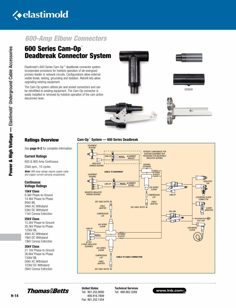
Elastimold’s 600 Series Cam-Op™ deadbreak connector system incorporates provisions for hotstick operation of de-energized primary feeder or network circuits. Configurations allow external visible break, testing, grounding and isolation. Retrofit kits allow upgrading existing equipment.
The Cam-Op system utilizes pin and socket connectors and can be retrofitted to existing equipment. The Cam-Op connector is easily installed or removed by hotstick operation of the cam action disconnect lever.
Ratings Overview
See page H-2 for complete information.
Current Ratings600 & 900 Amp Continuous
25kA sym., 10 cyclesNote: 900-amp ratings require copper cable and copper current-carrying components.
Continuous Voltage Ratings15kV Class 8.3kV Phase-to-Ground 14.4kV Phase-to-Phase 95kV BIL 34kV AC Withstand 53kV DC Withstand 11kV Corona Extinction
25kV Class 15.2kV Phase-to-Ground 26.3kV Phase-to-Phase 125kV BIL 40kV AC Withstand 78kV DC Withstand 19kV Corona Extinction
35kV Class 21.1kV Phase-to-Ground 36.6kV Phase-to-Phase 150kV BIL 50kV AC Withstand 103kV DC Withstand 26kV Corona Extinction
600 Series Cam-Op™ Deadbreak Connector System
Cam-Op™ System — 600 Series Deadbreak
insulated parking bushing
compression lug
cable adapter
compression lug
cable adapter
equipment bushing
equipment bushing
alignment bracket
cam-op
mounted insulated parking bushing
alignment busing
cam-op
CABLE TO EquipmEnT
see cable notes
see cable notes
see cable notes
cam-op
600 series elbow
retainer sleeves
600 series elbow
compression lug
cable adapter
bi-sop 2-point insulated
bushings
600 series elbow
retainer sleeves
bushing extender
retrofit components for exisiting equipment w/o
provisions for mountable insulated bushing
cam-op
visi link
CABLE TO CABLE COnnECTiOn
insulated cap
loadbreak elbowconnector
elbow arrester
test rod
grounding elbow
United StatesTel: 901.252.8000 800.816.7809Fax: 901.252.1354
Technical ServicesTel: 888.862.3289www.tnb.com
H-15
Power &
High Voltage — Elastim
old® Underground Cable Accessories
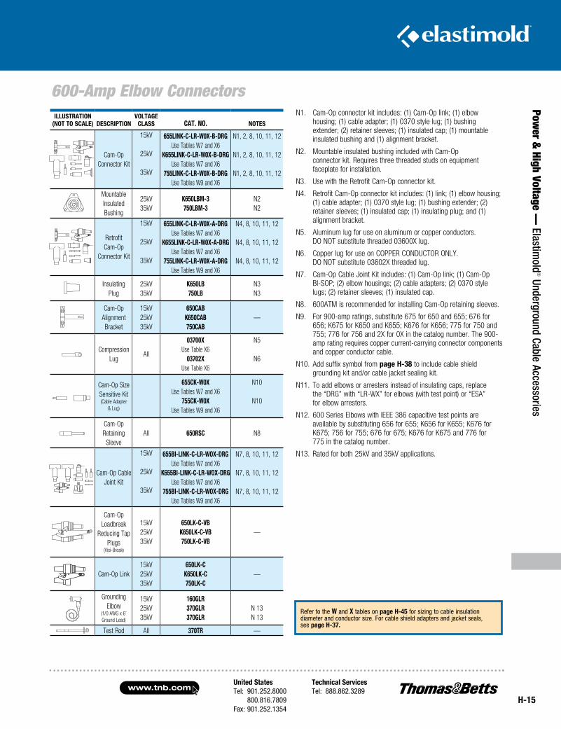
600-Amp Elbow ConnectorsiLLuSTRATiOn
(nOT TO SCALE) DESCRipTiOnVOLTAgE
CLASS CAT. nO. nOTES
Cam-Op Connector Kit
15kV
25kV
35kV
655LinK-C-LR-W0X-B-DRgUse Tables W7 and X6
K655LinK-C-LR-W0X-B-DRgUse Tables W7 and X6
755LinK-C-LR-W0X-B-DRgUse Tables W9 and X6
N1, 2, 8, 10, 11, 12
N1, 2, 8, 10, 11, 12
N1, 2, 8, 10, 11, 12
Mountable Insulated Bushing
25kV35kV
K650LBm-3750LBm-3
N2N2
Retrofit Cam-Op
Connector Kit
15kV
25kV
35kV
655LinK-C-LR-W0X-A-DRgUse Tables W7 and X6
K655LinK-C-LR-W0X-A-DRgUse Tables W7 and X6
755LinK-C-LR-W0X-A-DRgUse Tables W9 and X6
N4, 8, 10, 11, 12
N4, 8, 10, 11, 12
N4, 8, 10, 11, 12
Insulating Plug
25kV35kV
K650LB750LB
N3N3
Cam-Op Alignment Bracket
15kV25kV35kV
650CABK650CAB750CAB
—
Compression Lug
All
03700XUse Table X6
03702XUse Table X6
N5
N6
Cam-Op Size Sensitive Kit (Cable Adapter
& Lug)
655CK-W0XUse Tables W7 and X6
755CK-W0X Use Tables W9 and X6
N10
N10
Cam-Op Retaining
SleeveAll 650RSC N8
Cam-Op Cable Joint Kit
15kV
25kV
35kV
655Bi-LinK-C-LR-WOX-DRgUse Tables W7 and X6
K655Bi-LinK-C-LR-WOX-DRgUse Tables W7 and X6
755Bi-LinK-C-LR-WOX-DRgUse Tables W9 and X6
N7, 8, 10, 11, 12
N7, 8, 10, 11, 12
N7, 8, 10, 11, 12
Cam-Op Loadbreak
Reducing Tap Plugs
(Visi-Break)
15kV25kV35kV
650LK-C-VBK650LK-C-VB750LK-C-VB
—
Cam-Op Link15kV25kV35kV
650LK-CK650LK-C750LK-C
—
Grounding Elbow
(1/0 AWG x 6’ Ground Lead)
15kV25kV35kV
160gLR 370gLR 370gLR
N 13N 13
Test Rod All 370TR —
N1. Cam-Op connector kit includes: (1) Cam-Op link; (1) elbow housing; (1) cable adapter; (1) 0370 style lug; (1) bushing extender; (2) retainer sleeves; (1) insulated cap; (1) mountable insulated bushing and (1) alignment bracket.
N2. Mountable insulated bushing included with Cam-Op connector kit. Requires three threaded studs on equipment faceplate for installation.
N3. Use with the Retrofit Cam-Op connector kit.
N4. Retrofit Cam-Op connector kit includes: (1) link; (1) elbow housing; (1) cable adapter; (1) 0370 style lug; (1) bushing extender; (2) retainer sleeves; (1) insulated cap; (1) insulating plug; and (1) alignment bracket.
N5. Aluminum lug for use on aluminum or copper conductors. DO NOT substitute threaded 03600X lug.
N6. Copper lug for use on COPPER CONDUCTOR ONLY. DO NOT substitute 03602X threaded lug.
N7. Cam-Op Cable Joint Kit includes: (1) Cam-Op link; (1) Cam-Op BI-SOP; (2) elbow housings; (2) cable adapters; (2) 0370 style lugs; (2) retainer sleeves; (1) insulated cap.
N8. 600ATM is recommended for installing Cam-Op retaining sleeves.
N9. For 900-amp ratings, substitute 675 for 650 and 655; 676 for 656; K675 for K650 and K655; K676 for K656; 775 for 750 and 755; 776 for 756 and 2X for 0X in the catalog number. The 900-amp rating requires copper current-carrying connector components and copper conductor cable.
N10. Add suffix symbol from page H-38 to include cable shield grounding kit and/or cable jacket sealing kit.
N11. To add elbows or arresters instead of insulating caps, replace the “DRG” with “LR-WX” for elbows (with test point) or “ESA” for elbow arresters.
N12. 600 Series Elbows with IEEE 386 capacitive test points are available by substituting 656 for 655; K656 for K655; K676 for K675; 756 for 755; 676 for 675; K676 for K675 and 776 for 775 in the catalog number.
N13. Rated for both 25kV and 35kV applications.
Refer to the W and X tables on page H-45 for sizing to cable insulation diameter and conductor size. For cable shield adapters and jacket seals, see page H-37.
www.tnb.comUnited StatesTel: 901.252.8000 800.816.7809Fax: 901.252.1354
Technical ServicesTel: 888.862.3289
H-16
600-Amp Elbow Connectors
Pow
er &
Hig
h Vo
ltage
— E
last
imol
d® U
nder
grou
nd C
able
Acc
esso
ries
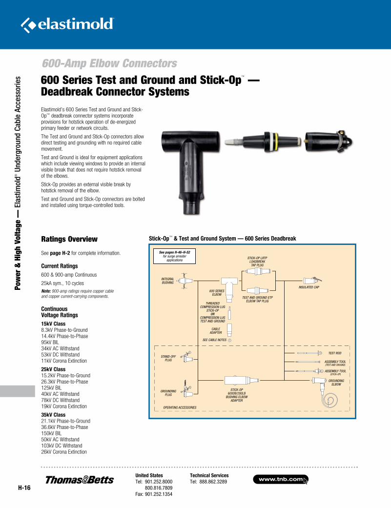
Elastimold’s 600 Series Test and Ground and Stick-Op™ deadbreak connector systems incorporate provisions for hotstick operation of de-energized primary feeder or network circuits.
The Test and Ground and Stick-Op connectors allow direct testing and grounding with no required cable movement.
Test and Ground is ideal for equipment applications which include viewing windows to provide an internal visible break that does not require hotstick removal of the elbows.
Stick-Op provides an external visible break by hotstick removal of the elbow.
Test and Ground and Stick-Op connectors are bolted and installed using torque-controlled tools.
Ratings Overview
See page H-2 for complete information.
Current Ratings600 & 900-amp Continuous
25kA sym., 10 cyclesNote: 900-amp ratings require copper cable and copper current-carrying components.
Continuous Voltage Ratings15kV Class 8.3kV Phase-to-Ground 14.4kV Phase-to-Phase 95kV BIL 34kV AC Withstand 53kV DC Withstand 11kV Corona Extinction
25kV Class 15.2kV Phase-to-Ground 26.3kV Phase-to-Phase 125kV BIL 40kV AC Withstand 78kV DC Withstand 19kV Corona Extinction
35kV Class 21.1kV Phase-to-Ground 36.6kV Phase-to-Phase 150kV BIL 50kV AC Withstand 103kV DC Withstand 26kV Corona Extinction
600 Series Test and Ground and Stick-Op™ —Deadbreak Connector Systems
Stick-Op™ & Test and Ground System — 600 Series Deadbreak
See pages H-46–H-52 for surge arrester
applications
integral bushing
threaded compression lug
stick-op or
compression lug test and ground
cable adapter
see cable notes
600 series elbow
test and ground etp elbow tap plug
stick-op lrtp loadbreak tap plug
insulated cap
stand-off plug
grounding plug
stick-op 600db/200lb
bushing elbow adapter
test rod
assembly tool (test and ground)
assembly tool (stick-op)
grounding elbow
operating accessories
H-17
Power &
High Voltage — Elastim
old® Underground Cable Accessories
600-Amp Elbow Connectors
United StatesTel: 901.252.8000 800.816.7809Fax: 901.252.1354
Technical ServicesTel: 888.862.3289www.tnb.com
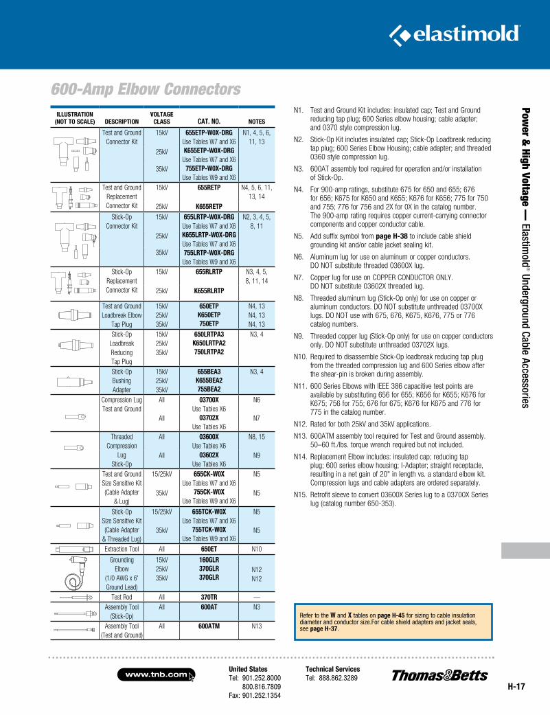
N1. Test and Ground Kit includes: insulated cap; Test and Ground reducing tap plug; 600 Series elbow housing; cable adapter; and 0370 style compression lug.
N2. Stick-Op Kit includes insulated cap; Stick-Op Loadbreak reducing tap plug; 600 Series Elbow Housing; cable adapter; and threaded 0360 style compression lug.
N3. 600AT assembly tool required for operation and/or installation of Stick-Op.
N4. For 900-amp ratings, substitute 675 for 650 and 655; 676 for 656; K675 for K650 and K655; K676 for K656; 775 for 750 and 755; 776 for 756 and 2X for 0X in the catalog number. The 900-amp rating requires copper current-carrying connector components and copper conductor cable.
N5. Add suffix symbol from page H-38 to include cable shield grounding kit and/or cable jacket sealing kit.
N6. Aluminum lug for use on aluminum or copper conductors. DO NOT substitute threaded 03600X lug.
N7. Copper lug for use on COPPER CONDUCTOR ONLY. DO NOT substitute 03602X threaded lug.
N8. Threaded aluminum lug (Stick-Op only) for use on copper or aluminum conductors. DO NOT substitute unthreaded 03700X lugs. DO NOT use with 675, 676, K675, K676, 775 or 776 catalog numbers.
N9. Threaded copper lug (Stick-Op only) for use on copper conductors only. DO NOT substitute unthreaded 03702X lugs.
N10. Required to disassemble Stick-Op loadbreak reducing tap plug from the threaded compression lug and 600 Series elbow after the shear-pin is broken during assembly.
N11. 600 Series Elbows with IEEE 386 capacitive test points are available by substituting 656 for 655; K656 for K655; K676 for K675; 756 for 755; 676 for 675; K676 for K675 and 776 for 775 in the catalog number.
N12. Rated for both 25kV and 35kV applications.
N13. 600ATM assembly tool required for Test and Ground assembly. 50–60 ft./lbs. torque wrench required but not included.
N14. Replacement Elbow includes: insulated cap; reducing tap plug; 600 series elbow housing; I-Adapter; straight receptacle, resulting in a net gain of 20" in length vs. a standard elbow kit. Compression lugs and cable adapters are ordered separately.
N15. Retrofit sleeve to convert 03600X Series lug to a 03700X Series lug (catalog number 650-353).
Refer to the W and X tables on page H-45 for sizing to cable insulation diameter and conductor size.For cable shield adapters and jacket seals, see page H-37.
IlluSTRaTIOn(nOT TO SCale) DeSCRIpTIOn
VOlTaGeClaSS CaT. nO. nOTeS
Test and GroundConnector Kit
15kV 655eTp-W0X-DRGUse Tables W7 and X6K655eTp-W0X-DRG
Use Tables W7 and X6755eTp-W0X-DRG
Use Tables W9 and X6
N1, 4, 5, 6,11, 13
25kV
35kV
Test and Ground Replacement Connector Kit
15kV 655ReTp N4, 5, 6, 11, 13, 14
25kV K655ReTpStick-Op
Connector Kit15kV 655lRTp-W0X-DRG
Use Tables W7 and X6K655lRTp-W0X-DRGUse Tables W7 and X6755lRTp-W0X-DRGUse Tables W9 and X6
N2, 3, 4, 5,8, 11
25kV
35kV
Stick-Op Replacement Connector Kit
15kV 655RlRTp N3, 4, 5, 8, 11, 14
25kV K655RlRTp
Test and Ground Loadbreak Elbow
Tap Plug
15kV25kV35kV
650eTpK650eTp750eTp
N4, 13N4, 13N4, 13
Stick-Op Loadbreak Reducing Tap Plug
15kV25kV35kV
650lRTpa3K650lRTpa2750lRTpa2
N3, 4
Stick-OpBushingAdapter
15kV25kV35kV
655Bea3K655Bea2755Bea2
N3, 4
Compression LugTest and Ground
All 03700XUse Tables X6
03702XUse Tables X6
N6
All N7
ThreadedCompression
LugStick-Op
All 03600XUse Tables X6
03602XUse Tables X6
N8, 15
All N9
Test and GroundSize Sensitive Kit(Cable Adapter
& Lug)
15/25kV 655CK-W0XUse Tables W7 and X6
755CK-W0XUse Tables W9 and X6
N5
35kV N5
Stick-OpSize Sensitive Kit(Cable Adapter
& Threaded Lug)
15/25kV 655TCK-W0XUse Tables W7 and X6
755TCK-W0XUse Tables W9 and X6
N5
35kV N5
Extraction Tool All 650eT N10
Grounding Elbow
(1/0 AWG x 6'Ground Lead)
15kV25kV35kV
160GlR370GlR370GlR
N12N12
Test Rod All 370TR —Assembly Tool
(Stick-Op)All 600aT N3
Assembly Tool(Test and Ground)
All 600aTM N13
www.tnb.comUnited StatesTel: 901.252.8000 800.816.7809Fax: 901.252.1354
Technical ServicesTel: 888.862.3289
H-18
ComboT Integral Separable Connectors
Pow
er &
Hig
h Vo
ltage
— E
last
imol
d® U
nder
grou
nd C
able
Acc
esso
ries
ComboT Integral Separable Connectors
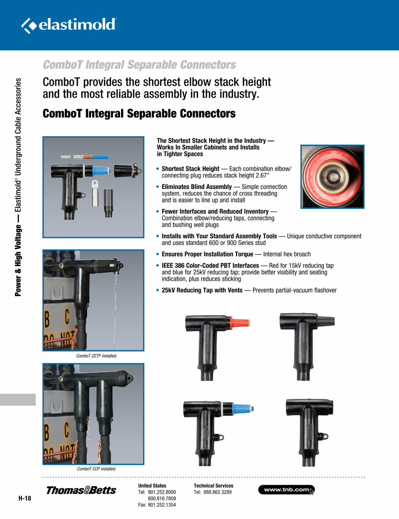
ComboT provides the shortest elbow stack height and the most reliable assembly in the industry.
The Shortest Stack Height in the Industry — Works In Smaller Cabinets and Installs in Tighter Spaces
• Shortest Stack Height — Each combination elbow/connecting plug reduces stack height 2.67"
• Eliminates Blind Assembly — Simple connection system, reduces the chance of cross threading and is easier to line up and install
• Fewer Interfaces and Reduced Inventory — Combination elbow/reducing taps, connecting and bushing well plugs
• Installs with Your Standard Assembly Tools — Unique conductive component and uses standard 600 or 900 Series stud
• Ensures Proper Installation Torque — Internal hex broach
• IEEE 386 Color-Coded PBT Interfaces — Red for 15kV reducing tap and blue for 25kV reducing tap; provide better visibility and seating indication, plus reduces sticking
• 25kV Reducing Tap with Vents — Prevents partial-vacuum flashover
ComboT CETP installed.
ComboT CCP installed.
United StatesTel: 901.252.8000 800.816.7809Fax: 901.252.1354
Technical ServicesTel: 888.862.3289www.tnb.com
ComboT Integral Separable Connectors
H-19
Power &
High Voltage — Elastim
old® Underground Cable Accessories
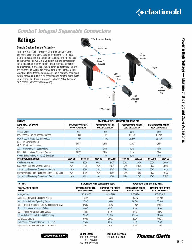
RatingsSimple Design, Simple AssemblyThe 15kV CETP and 15/25kV CCP simple design makes assembly quick and easy, utilizing a standard 5⁄8"–11 stud that is threaded into the equipment bushing. The hollow bore of the ComboT allows visual validation that the compression lug is positioned properly before the snuffer/bus is inserted and tightened. If preferred, the stud may be first threaded into the snuffer/bus. Again, the hollow bore of the ComboT allows visual validation that the compression lug is correctly positioned before proceeding. This is all accomplished with the same parts in a ComboT kit. There is no need to choose “Male Fastener” or “Female Fastener” when ordering.
RATIngS DEADBREAk WITH LoADBREAk REDuCIng TAP
BASE CATALog SERIESSERIES
655/656CETP SERIES600A DEADBREAk
675/676CETP SERIES900A DEADBREAk
k655/k656CETP SERIES600A DEADBREAk
k675/k676CETP SERIES900A DEADBREAk
Voltage Class 15kV 15kV 25kV 25kVMax. Phase-to-Ground Operating Voltage 8.3kV 8.3kV 15.2kV 15.2kVMax. Phase-to-Phase Operating Voltage 14.4kV 14.4kV 26.3kV 26.3kVBIL — Impulse Withstand (1.2 x 50 microsecond wave)
95kV 95kV 125kV 125kV
AC — One-Minute Withstand Voltage 34kV 34kV 40kV 40kVDC — Fifteen-Minute Withstand Voltage 53kV 53kV 78kV 78kVCorona Extinction Level @ 3.0 pC Sensitivity 11kV 11kV 19kV 19kVInTERFACE/ConnECTIon 600A DB 200A LB 900A DB 200A LB 600A DB 200A LB 900A DB 200A LB
Continuous Current 600A 200A 900A 200A 600A 200A 900A 200ALoadmake/Loadbreak Switching Current N/A 200A N/A 200A N/A 200A N/A 200ASymmetrical Momentary Current — 10 Cycle 25kA 10kA 25kA 10kA 25kA 10kA 25kA 10kASymmetrical One-Time Fault Close Current — 10 Cycle N/A 10kA N/A 10kA N/A 10kA N/A 10kASymmetrical Momentary Current — 3 Second 10kA 3.5kA 10kA 3.5kA 10kA 3.5kA 10kA 3.5kA
RATIngS DEADBREAk WITH ConnECTIng PLug DEADBREAk WITH BuSHIng WELL
BASE CATALog SERIESSERIES
k655k656 CCP SERIES600A DEADBREAk
k675k676 CCP SERIES900A DEADBREAk
k655k656 CBW SERIES600A DEADBREAk
k675k676 CBW SERIES900A DEADBREAk
Voltage Class 15/25/28kV 15/25/28kV 15/25/28kV 15/25/28kVMax. Phase-to-Ground Operating Voltage 16.2kV 16.2kV 16.2kV 16.2kVMax. Phase-to-Phase Operating Voltage 28.0kV 28.0kV 28.0kV 28.0kVBIL — Impluse Withstand (1.2 x 50 microsecond wave) 140kV 140kV 140kV 140kVAC — One-Minute Withstand Voltage 45kV 45kV 45kV 45kVDC — Fifteen-Minute Withstand Voltage 84kV 84kV 84kV 84kVCorona Extinction Level @ 3.0 pC Sensitivity 21.5kV 21.5kV 21.5kV 21.5kVContinuous Current 600A 900A 600A 900ASymmetrical Momentary Current — 10 Cycle 25kA 25kA 25kA 25kASymmetrical Momentary Current — 3 Second 10kA 10kA 10kA 10kA
CETP ComboT
Housing
DRG Insulated
Cap
Lug
Cable Adapter
600A Apparatus Bushing
650SA Stud
CCP ComboT
Housing
CCP Bus
DRG Insulated
Cap
CETP Snuffer Tube
www.tnb.comUnited StatesTel: 901.252.8000 800.816.7809Fax: 901.252.1354
Technical ServicesTel: 888.862.3289
H-20
ComboT Integral Separable Connectors
Pow
er &
Hig
h Vo
ltage
— E
last
imol
d® U
nder
grou
nd C
able
Acc
esso
ries
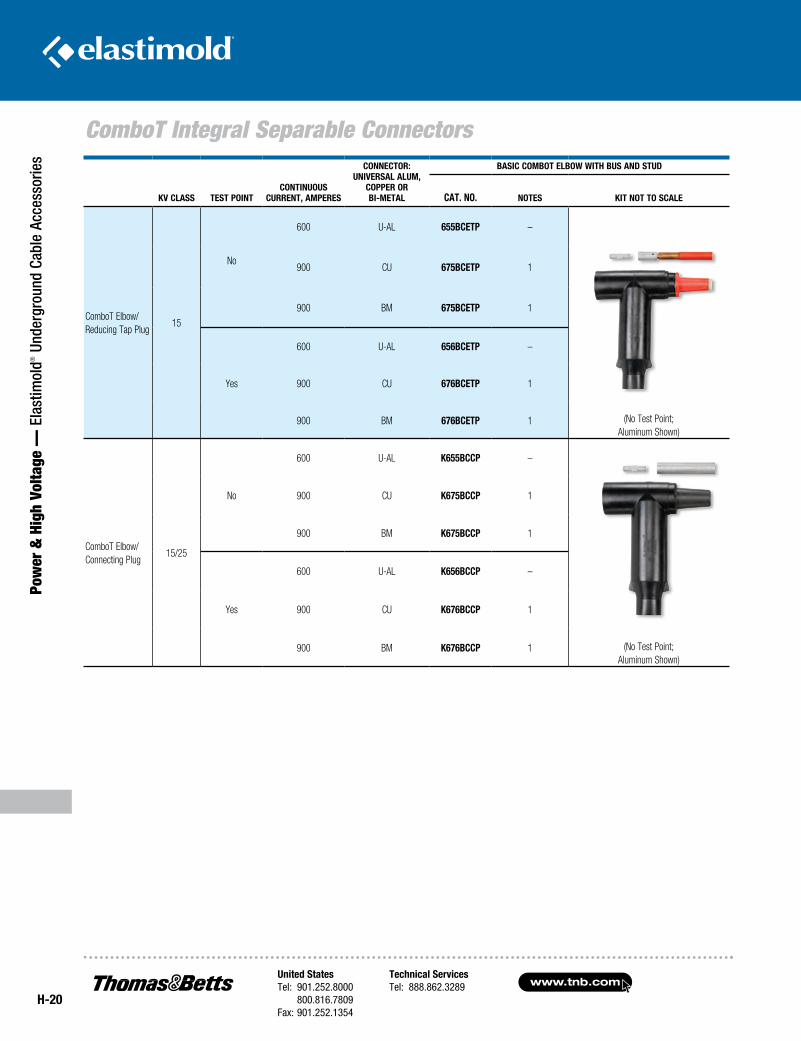
kV Class TesT PoinTConTinuous
CurrenT, amPeres
ConneCTor: uniVersal alum,
CoPPer or Bi-meTal
BasiC ComBoT elBow wiTH Bus and sTud
CaT. no. noTes kiT noT To sCale
ComboT Elbow/ Reducing Tap Plug
15
No
600 U-AL 655BCeTP –
(No Test Point;
Aluminum Shown)
900 CU 675BCeTP 1
900 BM 675BCeTP 1
Yes
600 U-AL 656BCeTP –
900 CU 676BCeTP 1
900 BM 676BCeTP 1
ComboT Elbow/ Connecting Plug
15/25
No
600 U-AL k655BCCP –
(No Test Point;
Aluminum Shown)
900 CU k675BCCP 1
900 BM k675BCCP 1
Yes
600 U-AL k656BCCP –
900 CU k676BCCP 1
900 BM k676BCCP 1
United StatesTel: 901.252.8000 800.816.7809Fax: 901.252.1354
Technical ServicesTel: 888.862.3289www.tnb.com
H-21
ComboT Integral Separable Connectors
Power &
High Voltage — Elastim
old® Underground Cable Accessories
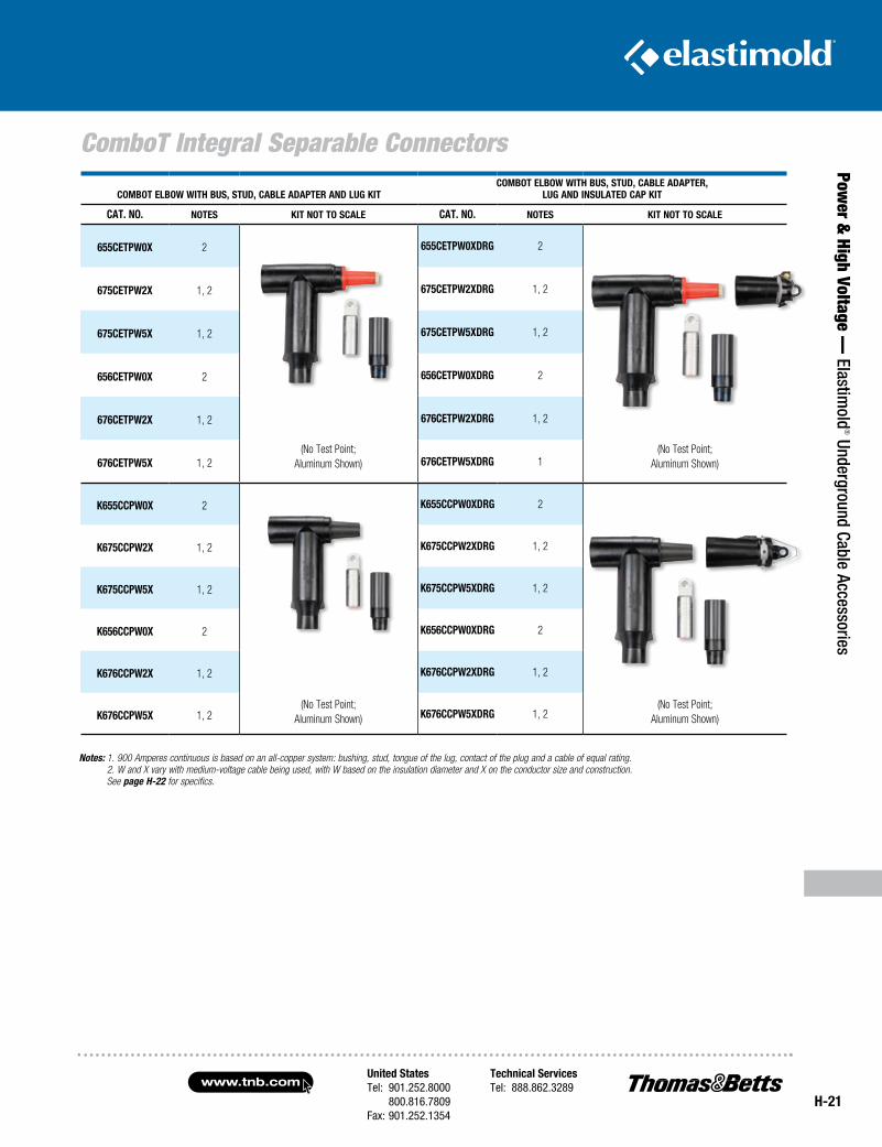
ComBoT elBow wiTH Bus, sTud, CaBle adaPTer and lug kiTComBoT elBow wiTH Bus, sTud, CaBle adaPTer,
lug and insulaTed CaP kiT
CaT. no. noTes kiT noT To sCale CaT. no. noTes kiT noT To sCale
655CeTPw0X 2
(No Test Point; Aluminum Shown)
655CeTPw0Xdrg 2
(No Test Point; Aluminum Shown)
675CeTPw2X 1, 2 675CeTPw2Xdrg 1, 2
675CeTPw5X 1, 2 675CeTPw5Xdrg 1, 2
656CeTPw0X 2 656CeTPw0Xdrg 2
676CeTPw2X 1, 2 676CeTPw2Xdrg 1, 2
676CeTPw5X 1, 2 676CeTPw5Xdrg 1
k655CCPw0X 2
(No Test Point; Aluminum Shown)
k655CCPw0Xdrg 2
(No Test Point; Aluminum Shown)
k675CCPw2X 1, 2 k675CCPw2Xdrg 1, 2
k675CCPw5X 1, 2 k675CCPw5Xdrg 1, 2
k656CCPw0X 2 k656CCPw0Xdrg 2
k676CCPw2X 1, 2 k676CCPw2Xdrg 1, 2
k676CCPw5X 1, 2 k676CCPw5Xdrg 1, 2
Notes: 1. 900 Amperes continuous is based on an all-copper system: bushing, stud, tongue of the lug, contact of the plug and a cable of equal rating. 2. W and X vary with medium-voltage cable being used, with W based on the insulation diameter and X on the conductor size and construction. See page H-22 for specifics.
www.tnb.comUnited StatesTel: 901.252.8000 800.816.7809Fax: 901.252.1354
Technical ServicesTel: 888.862.3289
H-22
ComboT Integral Separable Connectors
Pow
er &
Hig
h Vo
ltage
— E
last
imol
d® U
nder
grou
nd C
able
Acc
esso
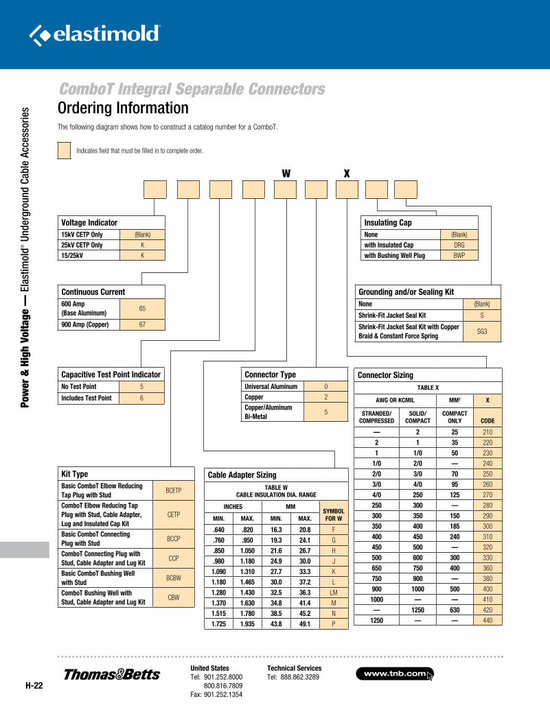
ries Ordering Information
The following diagram shows how to construct a catalog number for a ComboT.
Voltage Indicator15kV CETP Only (Blank)
25kV CETP Only K
15/25kV K
Continuous Current600 Amp (Base Aluminum)
65
900 Amp (Copper) 67
Capacitive Test Point IndicatorNo Test Point 5
Includes Test Point 6
Kit TypeBasic ComboT Elbow Reducing Tap Plug with Stud
BCETP
ComboT Elbow Reducing Tap Plug with Stud, Cable Adapter, Lug and Insulated Cap Kit
CETP
Basic ComboT Connecting Plug with Stud
BCCP
ComboT Connecting Plug with Stud, Cable Adapter and Lug Kit
CCP
Basic ComboT Bushing Wellwith Stud
BCBW
ComboT Bushing Well withStud, Cable Adapter and Lug Kit
CBW
Connector TypeUniversal Aluminum 0
Copper 2
Copper/Aluminum Bi-Metal
5
Cable Adapter SizingTABLE W
CABLE INSULATION DIA. RANgE
INCHES MMSyMBOL fOR WMIN. MAx. MIN. MAx.
.640 .820 16.3 20.8 F
.760 .950 19.3 24.1 G
.850 1.050 21.6 26.7 H
.980 1.180 24.9 30.0 J
1.090 1.310 27.7 33.3 K
1.180 1.465 30.0 37.2 L
1.280 1.430 32.5 36.3 LM
1.370 1.630 34.8 41.4 M
1.515 1.780 38.5 45.2 N
1.725 1.935 43.8 49.1 P
Insulating CapNone (Blank)
with Insulated Cap DRG
with Bushing Well Plug BWP
grounding and/or Sealing KitNone (Blank)
Shrink-fit Jacket Seal Kit S
Shrink-fit Jacket Seal Kit with Copper Braid & Constant force Spring
SG3
Connector SizingTABLE x
AWg OR KCMIL MM2 x
STRANDED/COMPRESSED
SOLID/COMPACT
COMPACT ONLy CODE
— 2 25 210
2 1 35 220
1 1/0 50 230
1/0 2/0 — 240
2/0 3/0 70 250
3/0 4/0 95 260
4/0 250 125 270
250 300 — 280
300 350 150 290
350 400 185 300
400 450 240 310
450 500 — 320
500 600 300 330
650 750 400 360
750 900 — 380
900 1000 500 400
1000 — — 410
— 1250 630 420
1250 — — 440
Indicates field that must be filled in to complete order.
W X
United StatesTel: 901.252.8000 800.816.7809Fax: 901.252.1354
Technical ServicesTel: 888.862.3289www.tnb.com
H-23
600-Amp Separable Cable Joints
Power &
High Voltage — Elastim
old® Underground Cable Accessories
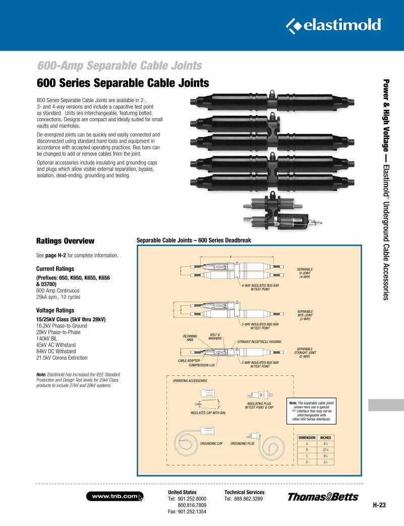
600 Series Separable Cable Joints are available in 2-, 3- and 4-way versions and include a capacitive test point as standard. Units are interchangeable, featuring bolted connections. Designs are compact and ideally suited for small vaults and manholes.
De-energized joints can be quickly and easily connected and disconnected using standard hand tools and equipment in accordance with accepted operating practices. Bus bars can be changed to add or remove cables from the joint.
Optional accessories include insulating and grounding caps and plugs which allow visible external separation, bypass, isolation, dead-ending, grounding and testing.
Ratings Overview
See page H-2 for complete information.
Current Ratings(Prefixes: 650, K650, K655, K656 & 03700)600 Amp Continuous25kA sym., 10 cycles
Voltage Ratings15/25kV Class (5kV thru 28kV) 16.2kV Phase-to-Ground 28kV Phase-to-Phase 140kV BIL 45kV AC Withstand 84kV DC Withstand 21.5kV Corona Extinction
Note: Elastimold has increased the IEEE Standard Prod uction and Design Test levels for 25kV Class products to include 27kV and 28kV systems.
600 Series Separable Cable Joints
Separable Cable Joints – 600 Series Deadbreak
Note: The separable cable joints shown here use a special
“Y” interface that may not be interchangeable with
other 600 Series interfaces.
operaTing acceSSorieS
Separable h-joinT (4-waY)
Separable wYe-joinT
(3-waY)
Separable STraighT joinT
(2-waY)
a
b
ac
4-waY inSulaTed buS bar w/TeST poinT
3-waY inSulaTed buS bar w/TeST poinT
2-waY inSulaTed buS bar w/TeST poinT
d
STraighT recepTacle houSing
bolT & waSherS
reTaining ring
cable adapTercompreSSion lug
inSulaTed cap wiTh bail
inSulaTing plug w/TeST poinT & cap
grounding cap grounding plug
DIMENSION INCHES
A 41⁄4
B 371⁄8
C 81⁄8
D 37⁄8
www.tnb.comUnited StatesTel: 901.252.8000 800.816.7809Fax: 901.252.1354
Technical ServicesTel: 888.862.3289
H-24
600-Amp Separable Cable Joints
Pow
er &
Hig
h Vo
ltage
— E
last
imol
d® U
nder
grou
nd C
able
Acc
esso
ries
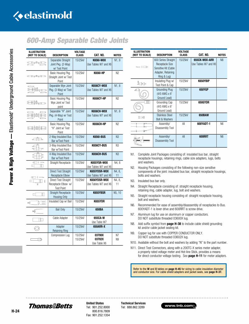
N1. Complete Joint Packages consisting of: insulated bus bar, straight receptacle housings, retaining rings, cable size adapters, lugs, bolts and washers.
N2. Housing Packages consisting of the following non-size sensitive components of the joint: insulated bus bar, straight receptacle housings, bolts and washers.
N3. Insulated bus bar only.
N4. Straight Receptacle consisting of: straight receptacle housing, retaining ring, cable adapter, lug, bolt and washers.
N5. Straight receptacle housing consisting of: straight receptacle housing, bolt and washers.
N6. Recommended for ease of assembly/disassembly of receptacles to Bus. 600YADT-1 is lever drive and 600RRT is screw drive.
N7. Aluminum lug for use on aluminum or copper conductors. DO NOT substitute threaded 03600X lug.
N8. Add suffix symbol from page H-38 to include cable shield grounding kit and/or cable jacket sealing kit.
N9. Copper lug for use with COPPER CONDUCTOR ONLY. DO NOT substitute threaded 03602X lug.
N10. Available without the bolt and washers by adding “N” to the part number.
N11. Direct Test Connectors, along with a 200TC-X series meter adapter, a properly rated voltage meter and Hot-line Stick, provides a means for direct conductor voltage testing. See page H-11 for meter adapters.
IllustratIon(not to scale) DescrIptIon
Voltageclass cat. no. notes
Separable Straight Joint Pkg. (2-Way)
w/ Test Point
15/25kV K656I-W0XUse Tables W7 and X6
N1, 8
Basic Housing Pkg. Straight Joint w/ Test
Point
15/25kV K656I-Hp N2
Separable Wye Joint Pkg. (3-Way) w/ Test
Point
15/25kV K656cY-W0XUse Tables W7 and X6
N1, 8
Basic Housing Pkg. Wye Joint w/ Test
point
15/25kV K656cY-Hp N2
Separable “H” Joint Pkg. (4-Way) w/ Test
Point
15/25kV K656cH-W0X Use Tables W7 and X6
N1, 8
Basic Housing Pkg. “H” Joint w/ Test
Point
15/25kV K656cH-Hp N2
2-Way Insulated Bus Bar w/Test Point
15/25kV K656I-Bus N3
3-Way Insulated Bus Bar w/Test Point
15/25kV K656cY-Bus N3
4-Way Insulated Bus Bar w/Test Point
15/25kV K656cH-Bus N3
Straight Receptacle 15/25kV K655Ysr-W0X Use Tables W7 and X6
N4, 8
Direct Test Straight Receptacle Elbow
15/25kV K655YDsr-W0X Use Tables W7 and X6
N4, 8, 11
Direct Test Straight Receptacle Elbow w/
Test Point
15/25kV K656YDsr-W0XUse Tables W7 and X6
N4, 8, 11
Straight Receptacle Housing Only
15/25kV K655YBsr N5, 10
Insulated Cap w/ Bail 15/25kV K655YDr
Bail Only 15/25kV 650Ba
Cable Adapter 15/25kV 655ca-WUse Table W7
Adapter Retaining Ring
15/25kV 650arr-X
Compression Lug 15/25kV 15/25kV
03700X03702X
Use Table X6
N7 N9
Refer to the W and X tables on page H-45 for sizing to cable insulation diameter and conductor size. For cable shield adapters and jacket seals, see page H-37.
IllustratIon(not to scale) DescrIptIon
Voltageclass cat. no. notes
600 Series Straight Receptacle Size
Sensitive Kit (Cable Adapter, Retaining
Ring & Lug)
15/25kV 655cK-W0X-arrUse Tables W7 and X6
N8
Insulating Plug w/Test Point & Cap
15/25kV K650YBIp
Grounding Plug(4/0 AWG x 6'Ground Lead)
15/25kV 650Ygp
Grounding Cap(4/0 AWG x 6'Ground Lead)
15/25kV 650gYDr
Stainless SteelBolt & Washers
15/25kV 650BaW
Assembly/Disassembly Tool
All 600YaDt-1 N6
Assembly/ Disassembly Tool
All 600rrt N6
United StatesTel: 901.252.8000 800.816.7809Fax: 901.252.1354
Technical ServicesTel: 888.862.3289www.tnb.com
H-25
Multi-Point Junctions
Power &
High Voltage — Elastim
old® Underground Cable Accessories
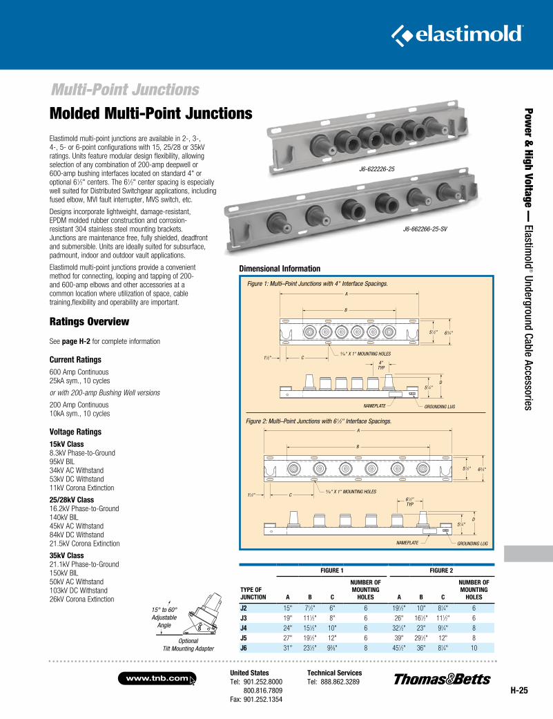
Elastimold multi-point junctions are available in 2-, 3-, 4-, 5- or 6-point configurations with 15, 25/28 or 35kV ratings. Units feature modular design flexibility, allowing selection of any combination of 200-amp deepwell or 600-amp bushing interfaces located on standard 4" or optional 61⁄2" centers. The 61⁄2" center spacing is especially well suited for Distributed Switchgear applications, including fused elbow, MVI fault interrupter, MVS switch, etc.
Designs incorporate lightweight, damage-resistant, EPDM molded rubber construction and corrosion- resistant 304 stainless steel mounting brackets. Junctions are maintenance free, fully shielded, deadfront and submersible. Units are ideally suited for subsurface, padmount, indoor and outdoor vault applications.
Elastimold multi-point junctions provide a convenient method for connecting, looping and tapping of 200- and 600-amp elbows and other accessories at a common location where utilization of space, cable training,flexibility and operability are important.
Ratings Overview
See page H-2 for complete information
current ratings600 Amp Continuous 25kA sym., 10 cycles
or with 200-amp Bushing Well versions
200 Amp Continuous 10kA sym., 10 cycles
Voltage ratings15kV class 8.3kV Phase-to-Ground 95kV BIL 34kV AC Withstand 53kV DC Withstand 11kV Corona Extinction
25/28kV class 16.2kV Phase-to-Ground 140kV BIL 45kV AC Withstand 84kV DC Withstand 21.5kV Corona Extinction
35kV class 21.1kV Phase-to-Ground 150kV BIL 50kV AC Withstand 103kV DC Withstand 26kV Corona Extinction
J6-622226-25
J6-662266-25-SV
Dimensional Information
OptionalTilt Mounting Adapter
tYpe of JunctIon
fIgure 1 fIgure 2
a B c
numBer ofmountIng
Holes a B c
numBer ofmountIng
Holes
J2 15" 71⁄2" 6" 6 191⁄2" 10" 81⁄4" 6J3 19" 111⁄2" 8" 6 26" 161⁄2" 111⁄2" 6J4 24" 151⁄2" 10" 6 321⁄2" 23" 91⁄4" 8J5 27" 191⁄2" 12" 6 39" 291⁄2" 12" 8J6 31" 231⁄2" 93⁄8" 8 451⁄2" 36" 81⁄4" 10
Molded Multi-Point Junctions
Figure 1: Multi–Point Junctions with 4" Interface Spacings.
9⁄16" x 1" MOunTIng hOleS
A
B
C
5 1⁄2" 6 3⁄4"
grOundIng lugnAMePlATe
4"TYP
d51⁄4"
grOundIng lug
Figure 2: Multi–Point Junctions with 6 1⁄2" Interface Spacings.
9⁄16" x 1" MOunTIng hOleS
A
B
51⁄2" 6 3⁄4"
C11⁄2"
nAMePlATe
61⁄2"TYP
d51⁄4"
11⁄2"
15° to 60° Adjustable
Angle
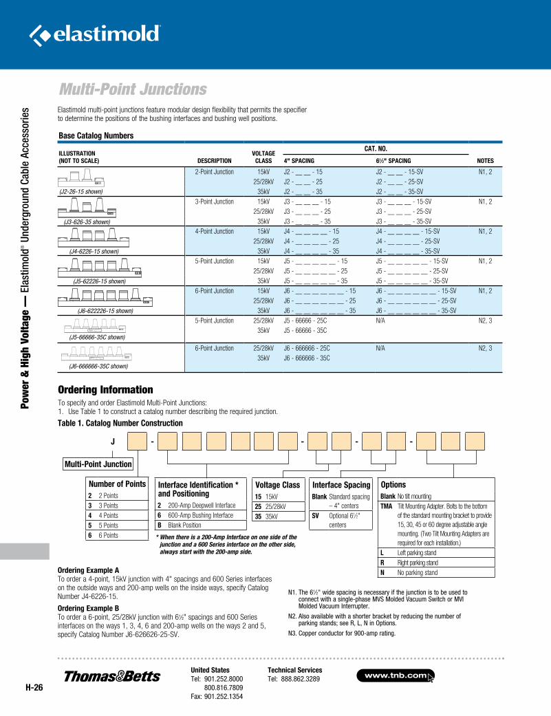
www.tnb.comUnited StatesTel: 901.252.8000 800.816.7809Fax: 901.252.1354
Technical ServicesTel: 888.862.3289
H-26
Multi-Point Junctions
Pow
er &
Hig
h Vo
ltage
— E
last
imol
d® U
nder
grou
nd C
able
Acc
esso
ries Elastimold multi-point junctions feature modular design flexibility that permits the specifier
to determine the positions of the bushing interfaces and bushing well positions.
Ordering InformationTo specify and order Elastimold Multi-Point Junctions: 1. Use Table 1 to construct a catalog number describing the required junction.
Ordering Example A To order a 4-point, 15kV junction with 4" spacings and 600 Series interfaces on the outside ways and 200-amp wells on the inside ways, specify Catalog Number J4-6226-15.
Ordering Example B To order a 6-point, 25/28kV junction with 61⁄2" spacings and 600 Series interfaces on the ways 1, 3, 4, 6 and 200-amp wells on the ways 2 and 5, specify Catalog Number J6-626626-25-SV.
Base Catalog Numbers
IllustrAtION (NOt tO sCAlE) DEsCrIptION
VOltAgE ClAss
CAt. NO.
NOtEs4" spACINg 61⁄2" spACINg
2-Point Junction 15kV J2 - __ __ - 15 J2 - __ __ - 15-SV N1, 225/28kV J2 - __ __ - 25 J2 - __ __ - 25-SV
35kV J2 - __ __ - 35 J2 - __ __ - 35-SV3-Point Junction 15kV J3 - __ __ __ - 15 J3 - __ __ __ - 15-SV N1, 2
25/28kV J3 - __ __ __ - 25 J3 - __ __ __ - 25-SV35kV J3 - __ __ __ - 35 J3 - __ __ __ - 35-SV
4-Point Junction 15kV J4 - __ __ __ __ - 15 J4 - __ __ __ __ - 15-SV N1, 225/28kV J4 - __ __ __ __ - 25 J4 - __ __ __ __ - 25-SV
35kV J4 - __ __ __ __ - 35 J4 - __ __ __ __ - 35-SV5-Point Junction 15kV J5 - __ __ __ __ __ - 15 J5 - __ __ __ __ __ - 15-SV N1, 2
25/28kV J5 - __ __ __ __ __ - 25 J5 - __ __ __ __ __ - 25-SV35kV J5 - __ __ __ __ __ - 35 J5 - __ __ __ __ __ - 35-SV
6-Point Junction 15kV J6 - __ __ __ __ __ __ - 15 J6 - __ __ __ __ __ __ - 15-SV N1, 225/28kV J6 - __ __ __ __ __ __ - 25 J6 - __ __ __ __ __ __ - 25-SV
35kV J6 - __ __ __ __ __ __ - 35 J6 - __ __ __ __ __ __ - 35-SV5-Point Junction 25/28kV J5 - 66666 - 25C N/A N2, 3
35kV J5 - 66666 - 35C
6-Point Junction 25/28kV J6 - 666666 - 25C N/A N2, 335kV J6 - 666666 - 35C
(J2-26-15 shown)
(J3-626-35 shown)
(J4-6226-15 shown)
(J5-62226-15 shown)
(J6-622226-15 shown)
(J5-66666-35C shown)
(J6-666666-35C shown)
table 1. Catalog Number Construction
Multi-point Junction
* When there is a 200-Amp Interface on one side of the junction and a 600 Series interface on the other side, always start with the 200-amp side.
J - - - -
Number of points 2 2 Points 3 3 Points 4 4 Points 5 5 Points 6 6 Points
Interface Identification * and positioning 2 200-Amp Deepwell Interface 6 600-Amp Bushing Interface B Blank Position
Voltage Class 15 15kV 25 25/28kV 35 35kV
Interface spacing Blank Standard spacing
– 4" centers sV Optional 61⁄2"
centers
Options Blank No tilt mounting tMA Tilt Mounting Adapter. Bolts to the bottom
of the standard mounting bracket to provide 15, 30, 45 or 60 degree adjustable angle mounting. (Two Tilt Mounting Adapters are required for each installation.)
l Left parking stand r Right parking stand N No parking stand
N1. The 61⁄2" wide spacing is necessary if the junction is to be used to connect with a single-phase MVS Molded Vacuum Switch or MVI Molded Vacuum Interrupter.
N2. Also available with a shorter bracket by reducing the number of parking stands; see R, L, N in Options.
N3. Copper conductor for 900-amp rating.
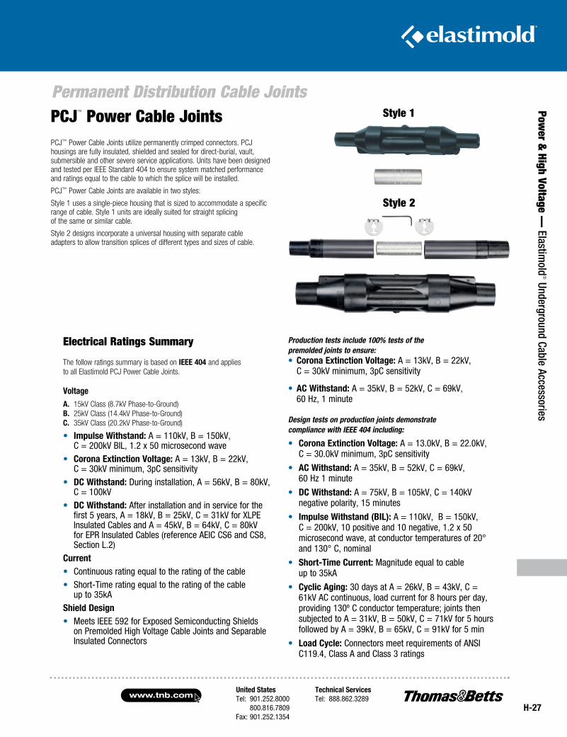
United StatesTel: 901.252.8000 800.816.7809Fax: 901.252.1354
Technical ServicesTel: 888.862.3289www.tnb.com
H-27
Permanent Distribution Cable Joints
Power &
High Voltage — Elastim
old® Underground Cable Accessories
PCJ™ Power Cable Joints utilize permanently crimped connectors. PCJ housings are fully in sulated, shielded and sealed for direct-burial, vault, submersible and other severe service applications. Units have been designed and tested per IEEE Standard 404 to ensure system matched performance and ratings equal to the cable to which the splice will be installed.
PCJ™ Power Cable Joints are available in two styles:
Style 1 uses a single-piece housing that is sized to accommodate a specific range of cable. Style 1 units are ideally suited for straight splicing of the same or similar cable.
Style 2 designs incorporate a universal housing with separate cable adapters to allow transition splices of different types and sizes of cable.
PCJ™ Power Cable Joints
Electrical Ratings Summary
The follow ratings summary is based on IEEE 404 and applies to all Elastimold PCJ Power Cable Joints.
VoltageA. 15kV Class (8.7kV Phase-to-Ground) B. 25kV Class (14.4kV Phase-to-Ground) C. 35kV Class (20.2kV Phase-to-Ground)
• Impulse Withstand: A = 110kV, B = 150kV, C = 200kV BIL, 1.2 x 50 microsecond wave
• Corona Extinction Voltage: A = 13kV, B = 22kV, C = 30kV minimum, 3pC sensitivity
• DC Withstand: During installation, A = 56kV, B = 80kV, C = 100kV
• DC Withstand: After installation and in service for the first 5 years, A = 18kV, B = 25kV, C = 31kV for XLPE Insulated Cables and A = 45kV, B = 64kV, C = 80kV for EPR Insulated Cables (reference AEIC CS6 and CS8, Section L.2)
Current• Continuous rating equal to the rating of the cable• Short-Time rating equal to the rating of the cable
up to 35kAshield Design• Meets IEEE 592 for Exposed Semiconducting Shields
on Premolded High Voltage Cable Joints and Separable Insulated Connectors
Production tests include 100% tests of the premolded joints to ensure:• Corona Extinction Voltage: A = 13kV, B = 22kV,
C = 30kV minimum, 3pC sensitivity
• AC Withstand: A = 35kV, B = 52kV, C = 69kV, 60 Hz, 1 minute
Design tests on production joints demonstrate compliance with IEEE 404 including:
• Corona Extinction Voltage: A = 13.0kV, B = 22.0kV, C = 30.0kV minimum, 3pC sensitivity
• AC Withstand: A = 35kV, B = 52kV, C = 69kV, 60 Hz 1 minute
• DC Withstand: A = 75kV, B = 105kV, C = 140kV negative polarity, 15 minutes
• Impulse Withstand (BIl): A = 110kV, B = 150kV, C = 200kV, 10 positive and 10 negative, 1.2 x 50 microsecond wave, at conductor temperatures of 20° and 130° C, nominal
• short-time Current: Magnitude equal to cable up to 35kA
• Cyclic Aging: 30 days at A = 26kV, B = 43kV, C = 61kV AC continuous, load current for 8 hours per day, providing 130º C conductor temperature; joints then subjected to A = 31kV, B = 50kV, C = 71kV for 5 hours followed by A = 39kV, B = 65kV, C = 91kV for 5 min
• load Cycle: Connectors meet require ments of ANSI C119.4, Class A and Class 3 ratings
Style 1
Style 2
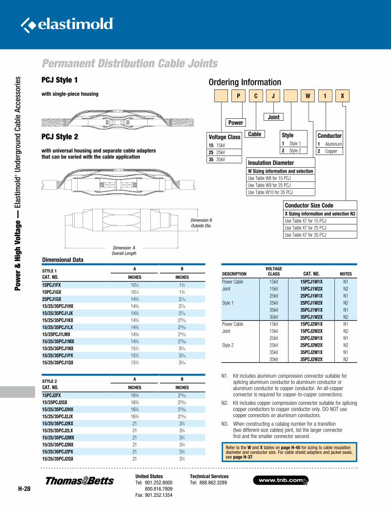
www.tnb.comUnited StatesTel: 901.252.8000 800.816.7809Fax: 901.252.1354
Technical ServicesTel: 888.862.3289
H-28
Permanent Distribution Cable Joints
Pow
er &
Hig
h Vo
ltage
— E
last
imol
d® U
nder
grou
nd C
able
Acc
esso
ries
Ordering InformationPCJ Style 1
with single-piece housing
PCJ Style 2
with universal housing and separate cable adapters that can be varied with the cable application
Dimension AOverall Length
Dimension BOutside Dia.
N1. Kit includes aluminum compression connector suitable for splicing aluminum conductor to aluminum conductor or aluminum conductor to copper conductor. An all-copper connector is required for copper-to-copper connections.
N2. Kit includes copper compression connector suitable for splicing copper conductors to copper conductor only. DO NOT use copper connectors on aluminum conductors.
N3. When constructing a catalog number for a transition (two different-size cables) joint, list the larger connector first and the smaller connector second.
DescriptionVoltage
class cat. no. notes
Power Cable 15kV 15pcJ1W1X N1Joint 15kV 15pcJ1W2X N2
25kV 25pcJ1W1X N1Style 1 25kV 25pcJ1W2X N2
35kV 35pcJ1W1X N135kV 35pcJ1W2X N2
Power Cable 15kV 15pcJ2W1X N1Joint 15kV 15pcJ2W2X N2
25kV 25pcJ2W1X N1Style 2 25kV 25pcJ2W2X N2
35kV 35pcJ2W1X N135kV 35pcJ2W2X N2
Dimensional Data
stYle 1 cat. no.
a B
incHes incHes
15pcJ1FX 101⁄4 13⁄415pcJ1gX 101⁄4 13⁄425pcJ1gX 143⁄8 27⁄16
15/25/35pcJ1HX 143⁄8 27⁄16
15/25/35pcJ1JX 143⁄8 27⁄16
15/25/35pcJ1KX 143⁄8 225⁄32
15/25/35pcJ1lX 143⁄8 225⁄32
15/25pcJ1lMX 143⁄8 225⁄32
15/25/35pcJ1MX 143⁄8 225⁄32
15/25/35pcJ1nX 153⁄4 33⁄16
15/25/35pcJ1pX 153⁄4 33⁄16
15/25/35pcJ1QX 153⁄4 33⁄16
stYle 2 cat. no.
a B
incHes incHes
15pcJ2FX 163⁄8 225⁄32
15/25pcJ2gX 163⁄8 225⁄32
15/25/35pcJ2HX 163⁄8 225⁄32
15/25/35pcJ2JX 163⁄8 225⁄32
15/25/35pcJ2KX 21 33⁄415/25/35pcJ2lX 21 33⁄415/25/35pcJ2MX 21 33⁄415/25/35pcJ2nX 21 33⁄415/25/35pcJ2pX 21 33⁄415/25/35pcJ2QX 21 33⁄4
Refer to the W and X tables on page H-45 for sizing to cable insulation diameter and conductor size. For cable shield adapters and jacket seals, see page H-37.
p c J W 1 X
style1 Style 12 Style 2
insulation DiameterW sizing information and selectionUse Table W8 for 15 PCJUse Table W9 for 25 PCJUse Table W10 for 35 PCJ
power
cable
Joint
conductor size codeX sizing information and selection n3Use Table X7 for 15 PCJUse Table X7 for 25 PCJUse Table X7 for 35 PCJ
conductor1 Aluminum2 Copper
Voltage class15 15kV25 25kV35 35kV
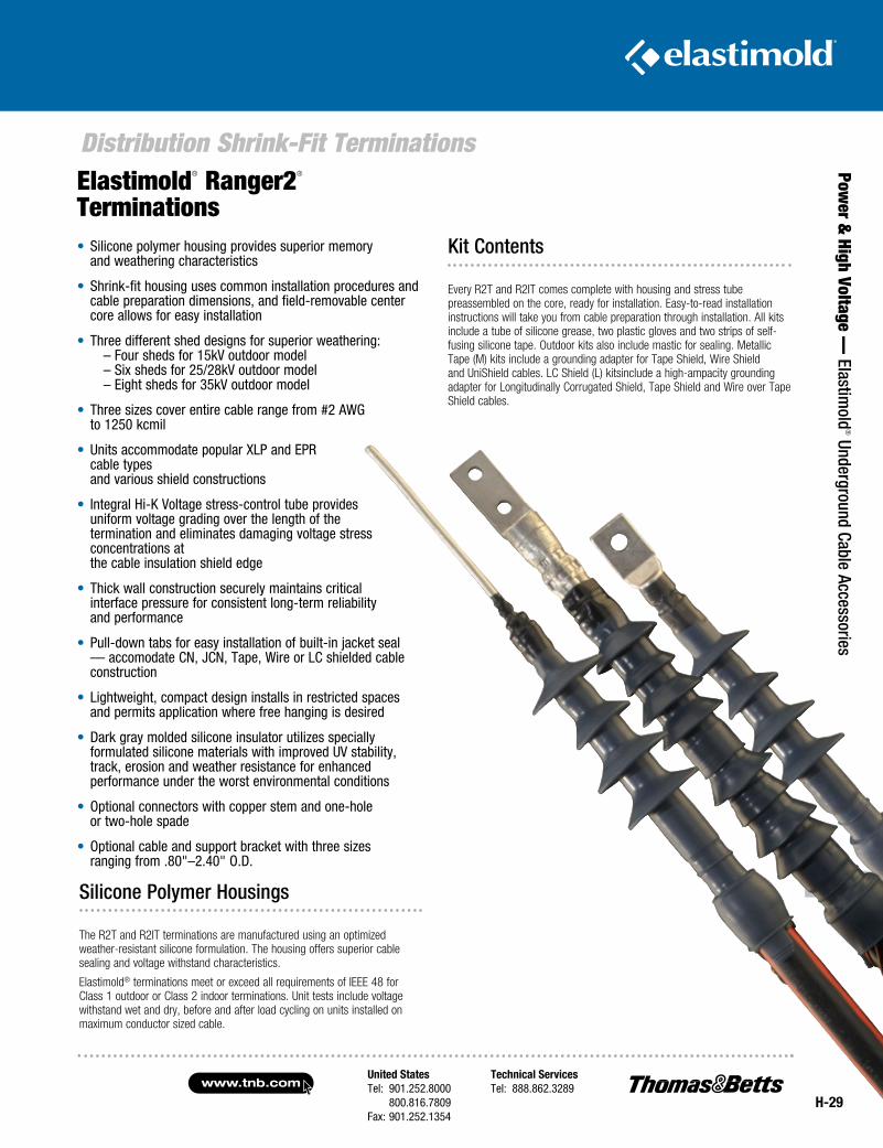
United StatesTel: 901.252.8000 800.816.7809Fax: 901.252.1354
Technical ServicesTel: 888.862.3289www.tnb.com
H-29
Distribution Shrink-Fit Terminations
Power &
High Voltage — Elastim
old® Underground Cable Accessories
Silicone Polymer Housings
The R2T and R2IT terminations are manufactured using an optimized weather-resistant silicone formulation. The housing offers superior cable sealing and voltage withstand characteristics.
Elastimold® terminations meet or exceed all requirements of IEEE 48 for Class 1 outdoor or Class 2 indoor terminations. Unit tests include voltage withstand wet and dry, before and after load cycling on units installed on maximum conductor sized cable.
Elastimold® Ranger2® Terminations• Silicone polymer housing provides superior memory
and weathering characteristics
• Shrink-fit housing uses common installation procedures and cable preparation dimensions, and field-removable center core allows for easy installation
• Three different shed designs for superior weathering: – Four sheds for 15kV outdoor model
– Six sheds for 25/28kV outdoor model – Eight sheds for 35kV outdoor model
• Three sizes cover entire cable range from #2 AWG to 1250 kcmil
• Units accommodate popular XLP and EPR cable types and various shield constructions
• Integral Hi-K Voltage stress-control tube provides uniform voltage grading over the length of the termination and eliminates damaging voltage stress concentrations at the cable insulation shield edge
• Thick wall construction securely maintains critical interface pressure for consistent long-term reliability and performance
• Pull-down tabs for easy installation of built-in jacket seal — accomodate CN, JCN, Tape, Wire or LC shielded cable construction
• Lightweight, compact design installs in restricted spaces and permits application where free hanging is desired
• Dark gray molded silicone insulator utilizes specially formulated silicone materials with improved UV stability, track, erosion and weather resistance for enhanced performance under the worst environmental conditions
• Optional connectors with copper stem and one-hole or two-hole spade
• Optional cable and support bracket with three sizes ranging from .80"–2.40" O.D.
Kit Contents
Every R2T and R2IT comes complete with housing and stress tube preassembled on the core, ready for installation. Easy-to-read installation instructions will take you from cable preparation through installation. All kits include a tube of silicone grease, two plastic gloves and two strips of self-fusing silicone tape. Outdoor kits also include mastic for sealing. Metallic Tape (M) kits include a grounding adapter for Tape Shield, Wire Shield and UniShield cables. LC Shield (L) kitsinclude a high-ampacity grounding adapter for Longitudinally Corrugated Shield, Tape Shield and Wire over Tape Shield cables.
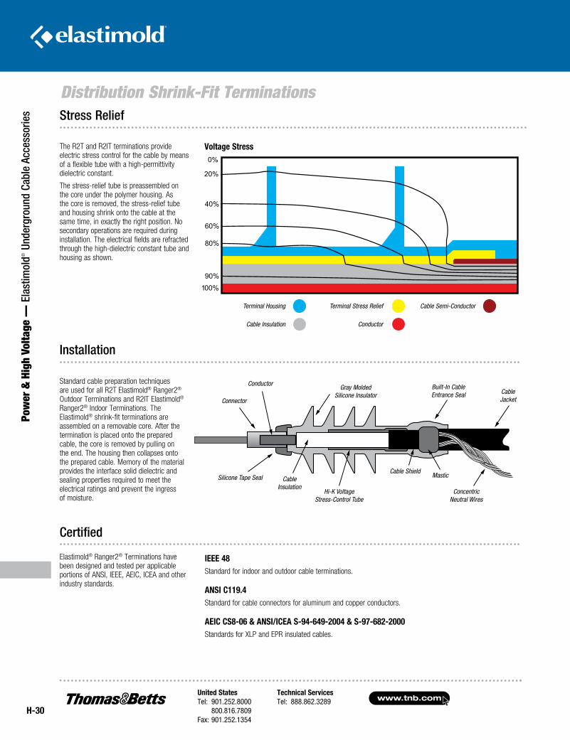
www.tnb.comUnited StatesTel: 901.252.8000 800.816.7809Fax: 901.252.1354
Technical ServicesTel: 888.862.3289
H-30
Distribution Shrink-Fit Terminations
Pow
er &
Hig
h Vo
ltage
— E
last
imol
d® U
nder
grou
nd C
able
Acc
esso
ries
IEEE 48 Standard for indoor and outdoor cable terminations.
ANSI C119.4Standard for cable connectors for aluminum and copper conductors.
AEIC CS8-06 & ANSI/ICEA S-94-649-2004 & S-97-682-2000 Standards for XLP and EPR insulated cables.
The R2T and R2IT terminations provide electric stress control for the cable by means of a flexible tube with a high-permittivity dielectric constant.
The stress-relief tube is preassembled on the core under the polymer housing. As the core is removed, the stress-relief tube and housing shrink onto the cable at the same time, in exactly the right position. No secondary operations are required during installation. The electrical fields are refracted through the high-dielectric constant tube and housing as shown.
Installation
Certified
Connector
Conductor Gray Molded Silicone Insulator
Built-In Cable Entrance Seal
Silicone Tape Seal Cable Insulation
Cable ShieldMastic
Concentric Neutral Wires
Hi-K Voltage Stress-Control Tube
Cable Jacket
STRESS RELIEF
Terminal Housing
Cable Insulation
Terminal Stress Relief Cable Semi-Conductor
Conductor
Voltage Stress
Stress Relief
Standard cable preparation techniques are used for all R2T Elastimold® Ranger2® Outdoor Terminations and R2IT Elastimold® Ranger2® Indoor Terminations. The Elastimold® shrink-fit terminations are assembled on a removable core. After the termination is placed onto the prepared cable, the core is removed by pulling on the end. The housing then collapses onto the prepared cable. Memory of the material provides the interface solid dielectric and sealing properties required to meet the electrical ratings and prevent the ingress of moisture.
Elastimold® Ranger2® Terminations have been designed and tested per applicable portions of ANSI, IEEE, AEIC, ICEA and other industry standards.
STRESS RELIEF
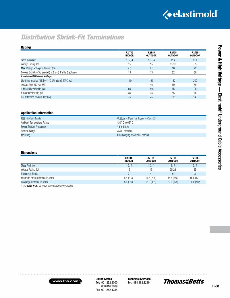
United StatesTel: 901.252.8000 800.816.7809Fax: 901.252.1354
Technical ServicesTel: 888.862.3289www.tnb.com
H-31
Distribution Shrink-Fit Terminations
Power &
High Voltage — Elastim
old® Underground Cable Accessories
RatingsR2IT15INdooR
R2T15ouTdooR
R2T28ouTdooR
R2T35ouTdooR
Sizes Available* 1, 2, 4 1, 2, 4 2, 4 2, 4Voltage Rating (kV) 15 15 25/28 35Max. Design Voltage to Ground (kV) 9.5 9.5 16 22Corona Extinction Voltage (kV) (≤3 p.c.) (Partial Discharge) 13 13 22 30Insulation Withstand Voltage:
Lightning Impulse (BIL Dry 110 Withstand) (kV Crest) 110 110 150 20010 Sec. Wet (60 Hz) (kV) — 45 60 801 Minute Dry (60 Hz) (kV) 50 50 65 905 Hour Dry (60 Hz) (kV) 35 35 55 75DC Withstand 15 Min. Dry (kV) 75 75 105 140
dimensionsR2IT15INdooR
R2T15 ouTdooR
R2T28 ouTdooR
R2T35 ouTdooR
Sizes Available* 1, 2, 4 1, 2, 4 2, 4 2, 4Voltage Rating (kV) 15 15 25/28 35Number of Sheds 0 4 6 8Minimum Strike Distance in. (mm) 8.4 (213) 11.6 (295) 14.5 (368) 16.8 (427)Creepage Distance in. (mm) 8.4 (213) 15.0 (381) 22.8 (579) 30.0 (762)* See page H-32 for cable insulation diameter ranges.
Application Information
IEEE 48 Classification Outdoor = Class 1A, Indoor = Class 2Ambient Temperature Range -30° C to 65° CPower System Frequency 48 to 62 HzAltitude Range 3,300 feet max.Mounting Free hanging or optional bracket
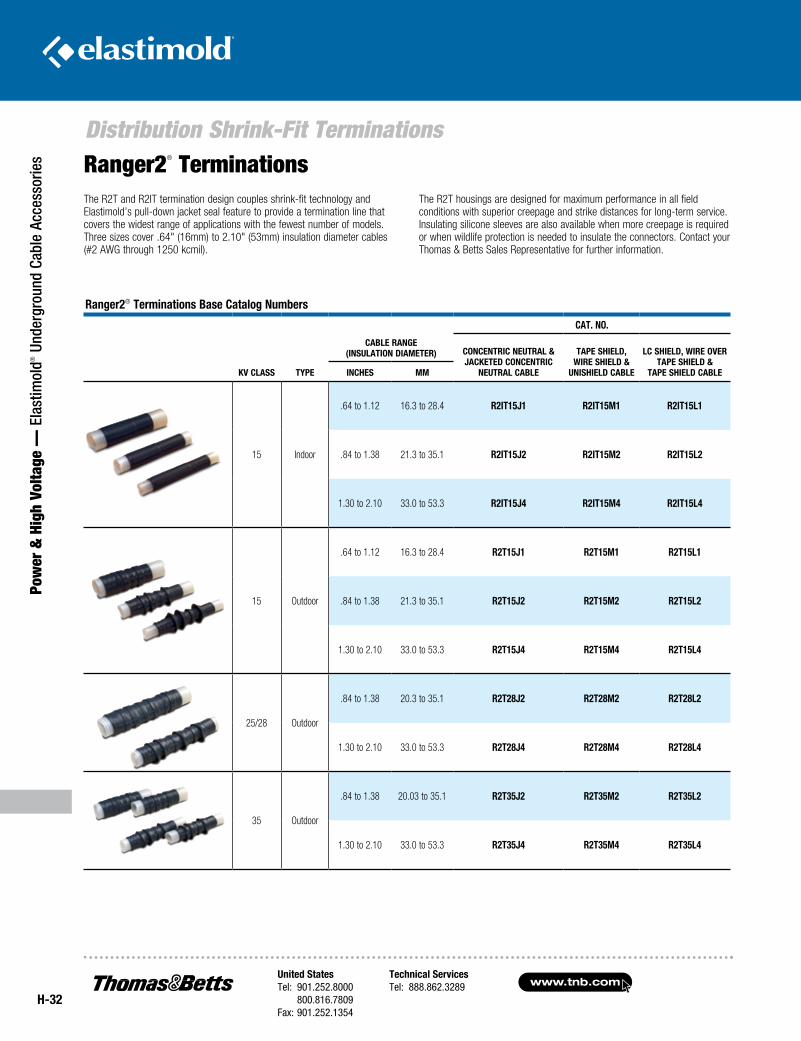
www.tnb.comUnited StatesTel: 901.252.8000 800.816.7809Fax: 901.252.1354
Technical ServicesTel: 888.862.3289
H-32
Distribution Shrink-Fit Terminations
Pow
er &
Hig
h Vo
ltage
— E
last
imol
d® U
nder
grou
nd C
able
Acc
esso
ries
The R2T and R2IT termination design couples shrink-fit technology and Elastimold’s pull-down jacket seal feature to provide a termination line that covers the widest range of applications with the fewest number of models. Three sizes cover .64" (16mm) to 2.10" (53mm) insulation diameter cables (#2 AWG through 1250 kcmil).
The R2T housings are designed for maximum performance in all field conditions with superior creepage and strike distances for long-term service. Insulating silicone sleeves are also available when more creepage is required or when wildlife protection is needed to insulate the connectors. Contact your Thomas & Betts Sales Representative for further information.
Ranger2® Terminations Base Catalog Numbers
kV Class Type
CaT. NO.
CaBle RaNge (INsulaTION DIameTeR) CONCeNTRIC NeuTRal &
JaCkeTeD CONCeNTRIC NeuTRal CaBle
Tape sHIelD, WIRe sHIelD &
uNIsHIelD CaBle
lC sHIelD, WIRe OVeR Tape sHIelD &
Tape sHIelD CaBleINCHes mm
15 Indoor
.64 to 1.12 16.3 to 28.4 R2IT15J1 R2IT15m1 R2IT15l1
.84 to 1.38 21.3 to 35.1 R2IT15J2 R2IT15m2 R2IT15l2
1.30 to 2.10 33.0 to 53.3 R2IT15J4 R2IT15m4 R2IT15l4
15 Outdoor
.64 to 1.12 16.3 to 28.4 R2T15J1 R2T15m1 R2T15l1
.84 to 1.38 21.3 to 35.1 R2T15J2 R2T15m2 R2T15l2
1.30 to 2.10 33.0 to 53.3 R2T15J4 R2T15m4 R2T15l4
25/28 Outdoor
.84 to 1.38 20.3 to 35.1 R2T28J2 R2T28m2 R2T28l2
1.30 to 2.10 33.0 to 53.3 R2T28J4 R2T28m4 R2T28l4
35 Outdoor
.84 to 1.38 20.03 to 35.1 R2T35J2 R2T35m2 R2T35l2
1.30 to 2.10 33.0 to 53.3 R2T35J4 R2T35m4 R2T35l4
Ranger2® Terminations
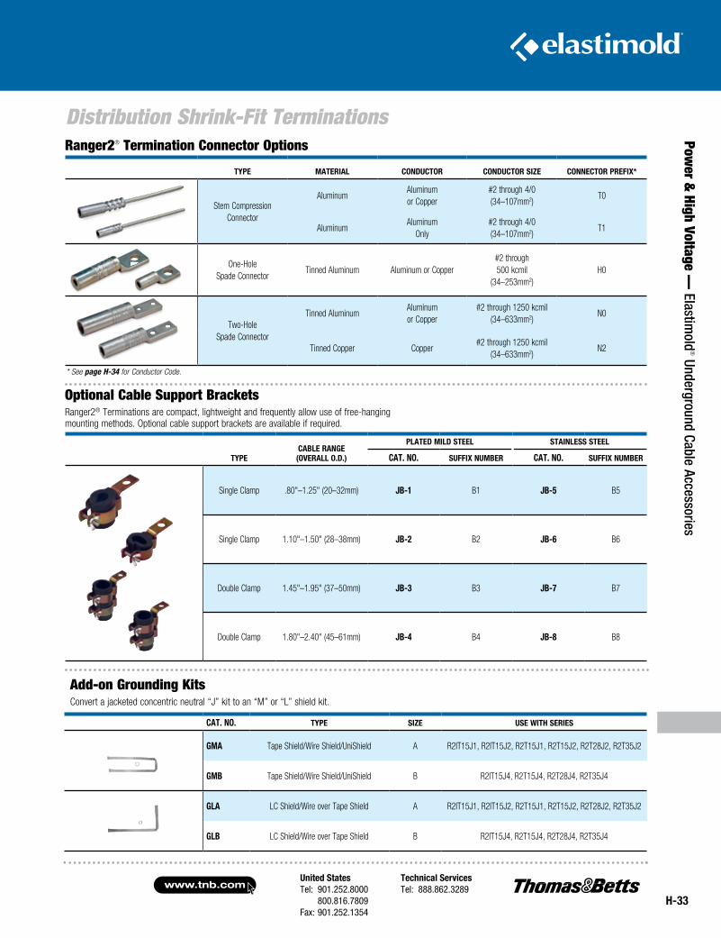
United StatesTel: 901.252.8000 800.816.7809Fax: 901.252.1354
Technical ServicesTel: 888.862.3289www.tnb.com
H-33
Distribution Shrink-Fit Terminations
Power &
High Voltage — Elastim
old® Underground Cable Accessories
TypeCaBle RaNge (OVeRall O.D.)
plaTeD mIlD sTeel sTaINless sTeel
CaT. NO. suffIx NumBeR CaT. NO. suffIx NumBeR
Single Clamp .80"–1.25" (20–32mm) JB-1 B1 JB-5 B5
Single Clamp 1.10"–1.50" (28–38mm) JB-2 B2 JB-6 B6
Double Clamp 1.45"–1.95" (37–50mm) JB-3 B3 JB-7 B7
Double Clamp 1.80"–2.40" (45–61mm) JB-4 B4 JB-8 B8
Ranger2® Termination Connector Options
Type maTeRIal CONDuCTOR CONDuCTOR sIze CONNeCTOR pRefIx*
Stem CompressionConnector
AluminumAluminum or Copper
#2 through 4/0 (34–107mm2)
T0
AluminumAluminum
Only#2 through 4/0 (34–107mm2)
T1
One-Hole
Spade ConnectorTinned Aluminum Aluminum or Copper
#2 through500 kcmil
(34–253mm2)H0
Two-HoleSpade Connector
Tinned AluminumAluminum or Copper
#2 through 1250 kcmil (34–633mm2)
N0
Tinned Copper Copper#2 through 1250 kcmil
(34–633mm2)N2
* See page H-34 for Conductor Code.
Optional Cable Support BracketsRanger2® Terminations are compact, lightweight and frequently allow use of free-hanging mounting methods. Optional cable support brackets are available if required.
Add-on Grounding KitsConvert a jacketed concentric neutral “J” kit to an “M” or “L” shield kit.
CaT. NO. Type sIze use WITH seRIes
gma Tape Shield/Wire Shield/UniShield A R2IT15J1, R2IT15J2, R2T15J1, R2T15J2, R2T28J2, R2T35J2
gmB Tape Shield/Wire Shield/UniShield B R2IT15J4, R2T15J4, R2T28J4, R2T35J4
gla LC Shield/Wire over Tape Shield A R2IT15J1, R2IT15J2, R2T15J1, R2T15J2, R2T28J2, R2T35J2
glB LC Shield/Wire over Tape Shield B R2IT15J4, R2T15J4, R2T28J4, R2T35J4
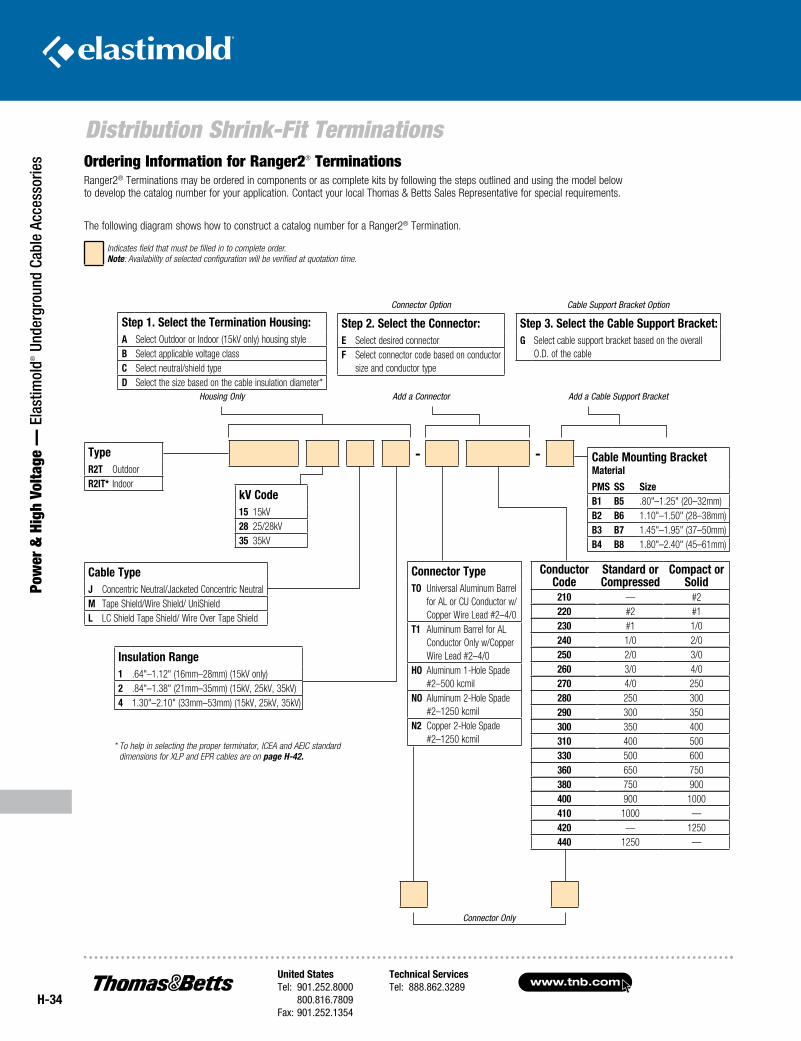
www.tnb.comUnited StatesTel: 901.252.8000 800.816.7809Fax: 901.252.1354
Technical ServicesTel: 888.862.3289
H-34
Distribution Shrink-Fit Terminations
Pow
er &
Hig
h Vo
ltage
— E
last
imol
d® U
nder
grou
nd C
able
Acc
esso
ries Ordering Information for Ranger2® Terminations
Ranger2® Terminations may be ordered in components or as complete kits by following the steps outlined and using the model below to develop the catalog number for your application. Contact your local Thomas & Betts Sales Representative for special requirements.
The following diagram shows how to construct a catalog number for a Ranger2® Termination.
Indicates field that must be filled in to complete order. Note: Availability of selected configuration will be verified at quotation time.
Connector Only
* To help in selecting the proper terminator, ICEA and AEIC standard dimensions for XLP and EPR cables are on page H-42.
- -TypeR2T OutdoorR2IT* Indoor
kV Code15 15kV28 25/28kV35 35kV
Step 1. Select the Termination Housing:A Select Outdoor or Indoor (15kV only) housing styleB Select applicable voltage classC Select neutral/shield typeD Select the size based on the cable insulation diameter*
Housing Only
Conductor Code
Standard or Compressed
Compact or Solid
210 — #2220 #2 #1230 #1 1/0240 1/0 2/0250 2/0 3/0260 3/0 4/0270 4/0 250280 250 300290 300 350300 350 400310 400 500330 500 600360 650 750380 750 900400 900 1000410 1000 —420 — 1250440 1250 —
Cable TypeJ Concentric Neutral/Jacketed Concentric NeutralM Tape Shield/Wire Shield/ UniShieldL LC Shield Tape Shield/ Wire Over Tape Shield
Connector Option
Step 2. Select the Connector:E Select desired connectorF Select connector code based on conductor
size and conductor type
Add a Connector
Cable Support Bracket Option
Step 3. Select the Cable Support Bracket:G Select cable support bracket based on the overall
O.D. of the cable
Add a Cable Support Bracket
Insulation Range1 .64"–1.12" (16mm–28mm) (15kV only)2 .84"–1.38" (21mm–35mm) (15kV, 25kV, 35kV)4 1.30"–2.10" (33mm–53mm) (15kV, 25kV, 35kV)
Connector TypeTO Universal Aluminum Barrel
for AL or CU Conductor w/Copper Wire Lead #2–4/0
T1 Aluminum Barrel for AL Conductor Only w/Copper Wire Lead #2–4/0
HO Aluminum 1-Hole Spade #2–500 kcmil
NO Aluminum 2-Hole Spade #2–1250 kcmil
N2 Copper 2-Hole Spade #2–1250 kcmil
Cable Mounting Bracket Material
PMS SS SizeB1 B5 .80"–1.25" (20–32mm)B2 B6 1.10"–1.50" (28–38mm)B3 B7 1.45"–1.95" (37–50mm)B4 B8 1.80"–2.40" (45–61mm)
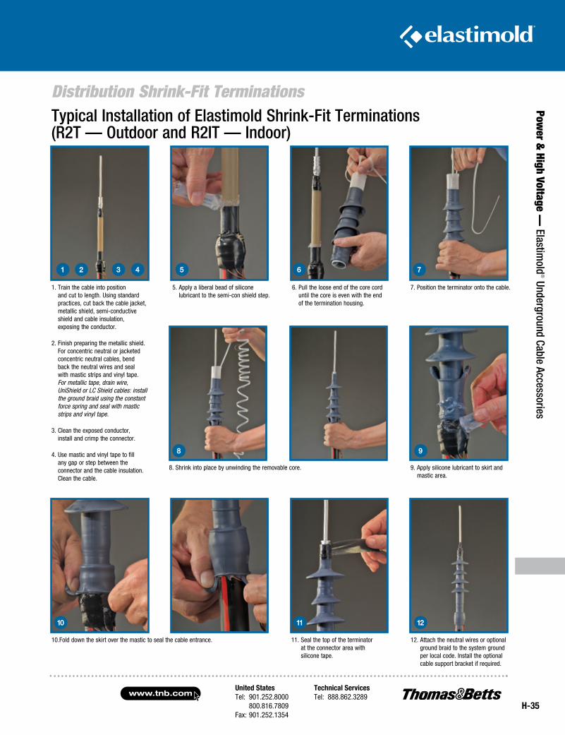
United StatesTel: 901.252.8000 800.816.7809Fax: 901.252.1354
Technical ServicesTel: 888.862.3289www.tnb.com
H-35
Distribution Shrink-Fit Terminations
Power &
High Voltage — Elastim
old® Underground Cable Accessories
Typical Installation of Elastimold Shrink-Fit Terminations (R2T — Outdoor and R2IT — Indoor)
1. Train the cable into position and cut to length. Using standard practices, cut back the cable jacket, metallic shield, semi-conductive shield and cable insulation, exposing the conductor.
2. Finish preparing the metallic shield. For concentric neutral or jacketed concentric neutral cables, bend back the neutral wires and seal with mastic strips and vinyl tape. For metallic tape, drain wire, UniShield or LC Shield cables: install the ground braid using the constant force spring and seal with mastic strips and vinyl tape.
3. Clean the exposed conductor, install and crimp the connector.
4. Use mastic and vinyl tape to fill any gap or step between the connector and the cable insulation. Clean the cable.
1
5. Apply a liberal bead of silicone lubricant to the semi-con shield step.
2 3 4 5
6. Pull the loose end of the core cord until the core is even with the end of the termination housing.
7. Position the terminator onto the cable.
6 7
10.Fold down the skirt over the mastic to seal the cable entrance. 11. Seal the top of the terminator at the connector area with silicone tape.
12. Attach the neutral wires or optional ground braid to the system ground per local code. Install the optional cable support bracket if required.
10 11 12
8. Shrink into place by unwinding the removable core. 9. Apply silicone lubricant to skirt and mastic area.
8 9
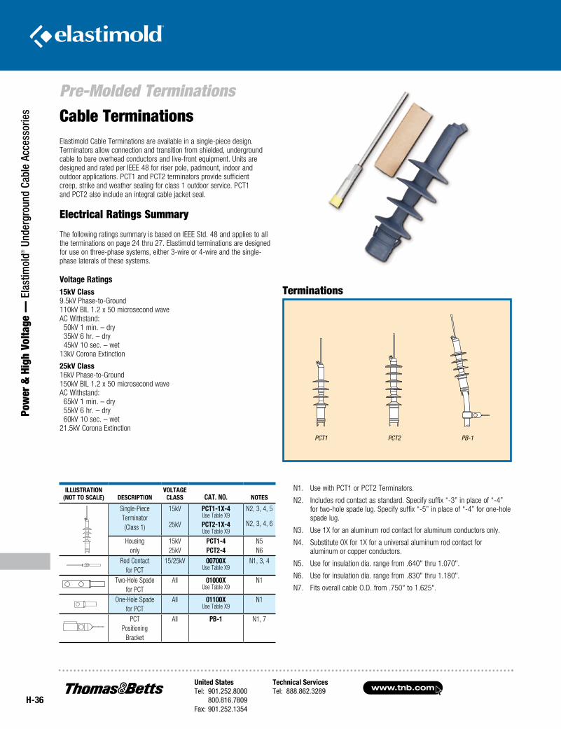
www.tnb.comUnited StatesTel: 901.252.8000 800.816.7809Fax: 901.252.1354
Technical ServicesTel: 888.862.3289
H-36
Pre-Molded Terminations
Pow
er &
Hig
h Vo
ltage
— E
last
imol
d® U
nder
grou
nd C
able
Acc
esso
ries
IllustratIon(not to scale) DescrIptIon
Voltageclass cat. no. notes
Single-Piece Terminator(Class 1)
15kV
25kV
pct1-1X-4Use Table X9
pct2-1X-4Use Table X9
N2, 3, 4, 5
N2, 3, 4, 6
Housingonly
15kV25kV
pct1-4pct2-4
N5N6
Rod Contactfor PCT
15/25kV 00700XUse Table X9
N1, 3, 4
Two-Hole Spadefor PCT
All 01000XUse Table X9
N1
One-Hole Spadefor PCT
All 01100XUse Table X9
N1
PCTPositioning
Bracket
All pB-1 N1, 7
N1. Use with PCT1 or PCT2 Terminators.
N2. Includes rod contact as standard. Specify suffix “-3” in place of “-4” for two-hole spade lug. Specify suffix “-5” in place of “-4” for one-hole spade lug.
N3. Use 1X for an aluminum rod contact for aluminum conductors only.
N4. Substitute 0X for 1X for a universal aluminum rod contact for aluminum or copper conductors.
N5. Use for insulation dia. range from .640" thru 1.070".
N6. Use for insulation dia. range from .830" thru 1.180".
N7. Fits overall cable O.D. from .750" to 1.625".
Electrical Ratings Summary
The following ratings summary is based on IEEE Std. 48 and applies to all the terminations on page 24 thru 27. Elastimold terminations are designed for use on three-phase systems, either 3-wire or 4-wire and the single-phase laterals of these systems.
Voltage ratings15kV class 9.5kV Phase-to-Ground 110kV BIL 1.2 x 50 microsecond wave AC Withstand: 50kV 1 min. – dry 35kV 6 hr. – dry 45kV 10 sec. – wet 13kV Corona Extinction
25kV class 16kV Phase-to-Ground 150kV BIL 1.2 x 50 microsecond wave AC Withstand: 65kV 1 min. – dry 55kV 6 hr. – dry 60kV 10 sec. – wet 21.5kV Corona Extinction
Cable TerminationsElastimold Cable Terminations are available in a single-piece design. Terminators allow connection and transition from shielded, underground cable to bare overhead conductors and live-front equipment. Units are designed and rated per IEEE 48 for riser pole, padmount, indoor and outdoor applications. PCT1 and PCT2 terminators provide sufficient creep, strike and weather sealing for class 1 outdoor service. PCT1 and PCT2 also include an integral cable jacket seal.
Terminations
BRACKETS
PB-1PCT-1 PCT-2
SINGLE PIECE TERMINATORS
PCT1 PCT2 PB-1
BRACKETS
PB-1PCT-1 PCT-2
SINGLE PIECE TERMINATORS
BRACKETS
PB-1PCT-1 PCT-2
SINGLE PIECE TERMINATORS
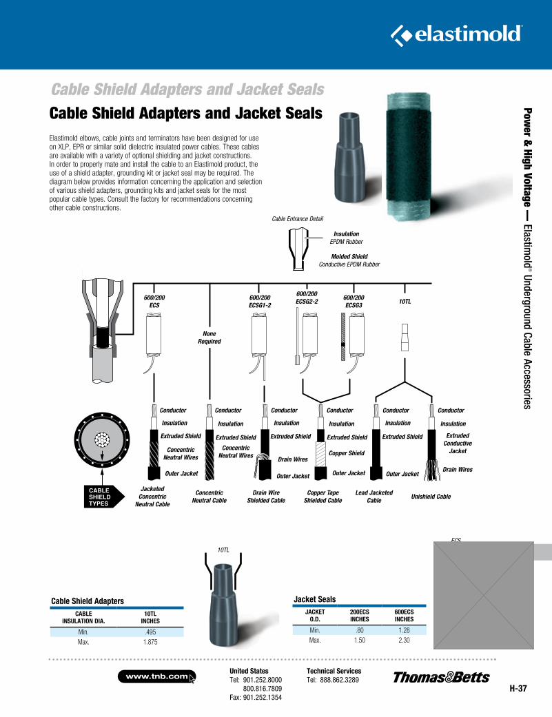
United StatesTel: 901.252.8000 800.816.7809Fax: 901.252.1354
Technical ServicesTel: 888.862.3289www.tnb.com
H-37
Cable Shield Adapters and Jacket Seals
Power &
High Voltage — Elastim
old® Underground Cable Accessories
CONCENTRICNEUTRAL
CABLE
JACKETEDCONCENTRIC
NEUTRALCABLE
DRAINWIRE
SHIELDEDCABLE
COPPERTAPE
SHIELDEDCABLE
LEADJACKETED
CABLE
UNISHIELDCABLE
600/200ECS
600/200ECSG1-2
600/200ECSG2-2
600/200ECSG3
NONEREQUIRED
10TL
CONDUCTOR
INSULATION
EXTRUDED SHIELD
CONCENTRIC NEUTRAL WIRES
OUTER JACKET
CONDUCTOR
INSULATION
EXTRUDED SHIELD
DRAIN WIRES
OUTER JACKET
CONDUCTOR
INSULATION
EXTRUDED SHIELD
COPPER SHIELD
OUTER JACKET
CONDUCTOR
INSULATION
EXTRUDED SHIELD
OUTER JACKET
CONDUCTOR
INSULATION
EXTRUDED CONDUCTIVE JACKET
DRAIN WIRES
CONDUCTOR
INSULATION
EXTRUDED SHIELD
CONCENTRIC NEUTRAL WIRES
CABLE ENTRANCE DETAIL
INSULATIONEPDM RUBBER
MOLDED SHIELDCONDUCTIVE EPDM RUBBER
CABLESHIELDTYPES
ECS
cable shield adapterscaBle
InsulatIon DIa.10tl
IncHes
Min. .495Max. 1.875
Jacket sealsJacket
o.D.200ecsIncHes
600ecsIncHes
Min. .80 1.28Max. 1.50 2.30
Cable Shield Adapters and Jacket Seals
10TL
Elastimold elbows, cable joints and terminators have been designed for use on XLP, EPR or similar solid dielectric insulated power cables. These cables are available with a variety of optional shielding and jacket constructions. In order to properly mate and install the cable to an Elastimold product, the use of a shield adapter, grounding kit or jacket seal may be required. The diagram below provides information concerning the application and selection of various shield adapters, grounding kits and jacket seals for the most popular cable types. Consult the factory for recommendations concerning other cable constructions.
Cable Entrance Detail
Insulation EPDM Rubber
Molded Shield Conductive EPDM Rubber
10TL600/200 ECSG3
600/200 ECSG2-2600/200
ECSG1-2600/200
ECS
Conductor Conductor
None Required
Conductor Conductor Conductor Conductor
Insulation Insulation Insulation Insulation Insulation Insulation
Extruded Shield Extruded Shield
Copper Shield
Extruded Shield Extruded Shield Extruded Shield Extruded Conductive
JacketConcentric Neutral Wires
Concentric Neutral Wires
Jacketed Concentric
Neutral Cable
Concentric Neutral Cable
Drain Wire Shielded Cable
Copper Tape Shielded Cable
Lead Jacketed Cable Unishield Cable
Outer Jacket Outer Jacket Outer Jacket Outer Jacket
Drain Wires
Drain Wires
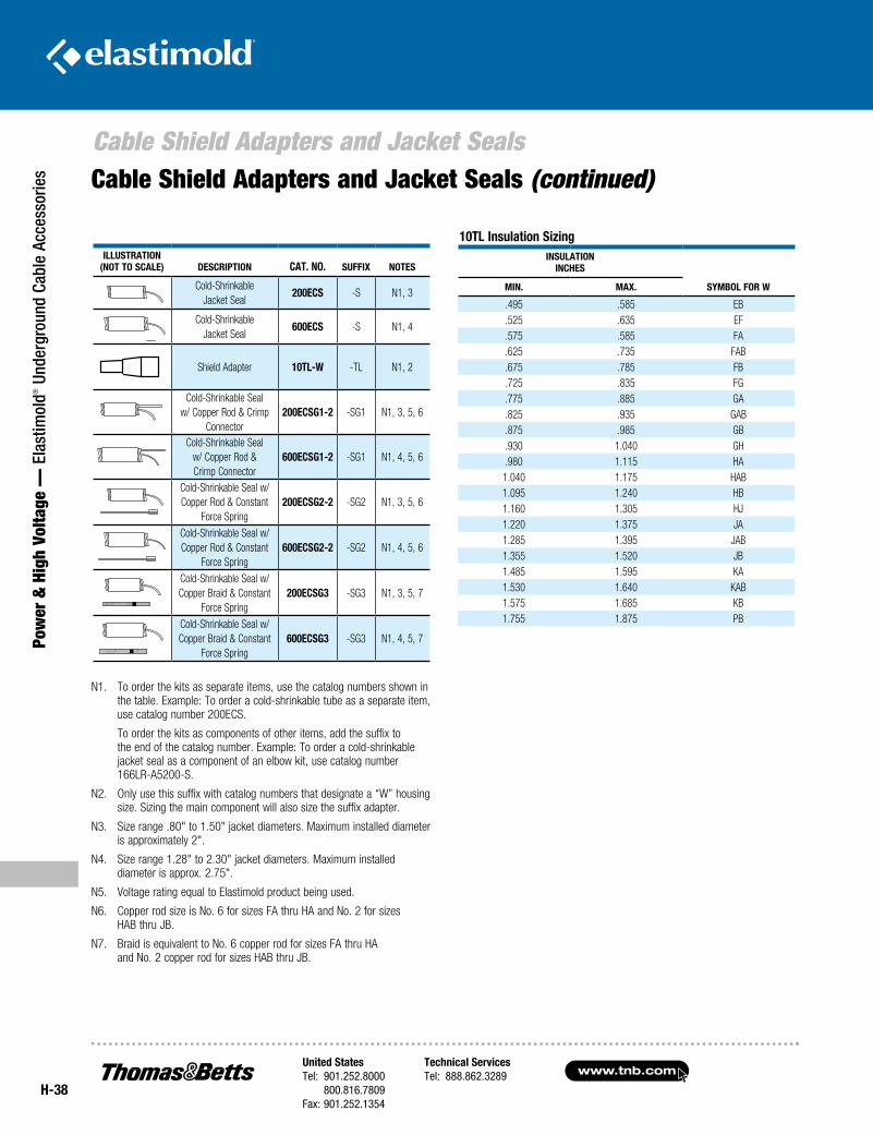
www.tnb.comUnited StatesTel: 901.252.8000 800.816.7809Fax: 901.252.1354
Technical ServicesTel: 888.862.3289
H-38
Cable Shield Adapters and Jacket Seals
Pow
er &
Hig
h Vo
ltage
— E
last
imol
d® U
nder
grou
nd C
able
Acc
esso
ries
IllustratIon(not to scale) DescrIptIon cat. no. suffIx notes
Cold-Shrinkable Jacket Seal
200ecs -S N1, 3
Cold-Shrinkable Jacket Seal
600ecs -S N1, 4
Shield Adapter 10tl-W -TL N1, 2
Cold-Shrinkable Seal w/ Copper Rod & Crimp
Connector200ecsG1-2 -SG1 N1, 3, 5, 6
Cold-Shrinkable Sealw/ Copper Rod &Crimp Connector
600ecsG1-2 -SG1 N1, 4, 5, 6
Cold-Shrinkable Seal w/ Copper Rod & Constant
Force Spring200ecsG2-2 -SG2 N1, 3, 5, 6
Cold-Shrinkable Seal w/ Copper Rod & Constant
Force Spring 600ecsG2-2 -SG2 N1, 4, 5, 6
Cold-Shrinkable Seal w/ Copper Braid & Constant
Force Spring200ecsG3 -SG3 N1, 3, 5, 7
Cold-Shrinkable Seal w/ Copper Braid & Constant
Force Spring600ecsG3 -SG3 N1, 4, 5, 7
N1. To order the kits as separate items, use the catalog numbers shown in the table. Example: To order a cold-shrinkable tube as a separate item, use catalog number 200ECS.
To order the kits as components of other items, add the suffix to the end of the catalog number. Example: To order a cold-shrinkable jacket seal as a component of an elbow kit, use catalog number 166LR-A5200-S.
N2. Only use this suffix with catalog numbers that designate a “W” housing size. Sizing the main component will also size the suffix adapter.
N3. Size range .80" to 1.50" jacket diameters. Maximum installed diameter is approximately 2".
N4. Size range 1.28" to 2.30" jacket diameters. Maximum installed diameter is approx. 2.75".
N5. Voltage rating equal to Elastimold product being used.
N6. Copper rod size is No. 6 for sizes FA thru HA and No. 2 for sizes HAB thru JB.
N7. Braid is equivalent to No. 6 copper rod for sizes FA thru HA and No. 2 copper rod for sizes HAB thru JB.
10tl Insulation sizingInsulatIon
IncHes
symbol for WmIn. max.
.495 .585 EB
.525 .635 EF
.575 .585 FA
.625 .735 FAB
.675 .785 FB
.725 .835 FG
.775 .885 GA
.825 .935 GAB
.875 .985 GB
.930 1.040 GH
.980 1.115 HA1.040 1.175 HAB1.095 1.240 HB1.160 1.305 HJ1.220 1.375 JA1.285 1.395 JAB1.355 1.520 JB1.485 1.595 KA1.530 1.640 KAB1.575 1.685 KB1.755 1.875 PB
Cable Shield Adapters and Jacket Seals (continued)
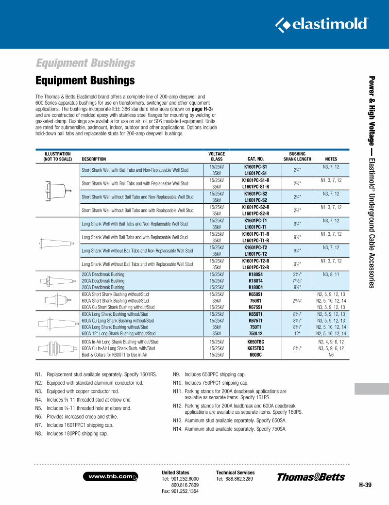
United StatesTel: 901.252.8000 800.816.7809Fax: 901.252.1354
Technical ServicesTel: 888.862.3289www.tnb.com
H-39
Equipment Bushings
Power &
High Voltage — Elastim
old® Underground Cable Accessories
N1. Replacement stud available separately. Specify 1601RS.
N2. Equipped with standard aluminum conductor rod.
N3. Equipped with copper conductor rod.
N4. Includes 5⁄8-11 threaded stud at elbow end.
N5. Includes 5⁄8-11 threaded hole at elbow end.
N6. Provides increased creep and strike.
N7. Includes 1601PPC1 shipping cap.
N8. Includes 180PPC shipping cap.
N9. Includes 650PPC shipping cap.
N10. Includes 750PPC1 shipping cap.
N11. Parking stands for 200A deadbreak applications are available as separate items. Specify 151PS.
N12. Parking stands for 200A loadbreak and 600A deadbreak applications are available as separate items. Specify 160PS.
N13. Aluminum stud available separately. Specify 650SA.
N14. Aluminum stud available separately. Specify 750SA.
Equipment BushingsThe Thomas & Betts Elastimold brand offers a complete line of 200-amp deep well and 600 Series apparatus bushings for use on transformers, switchgear and other equipment applications. The bushings incorporate IEEE 386 standard interfaces (shown on page H-3) and are constructed of molded epoxy with stainless steel flanges for mounting by welding or gasketed clamp. Bushings are available for use on air, oil or SF6 insulated equipment. Units are rated for submersible, padmount, indoor, outdoor and other applications. Options include hold-down bail tabs and replaceable studs for 200-amp deepwell bushings.
IllustratIon(not to scale) DescrIptIon
VoltaGeclass cat. no.
busHInGsHank lenGtH notes
Short Shank Well with Bail Tabs and Non-Replaceable Well Stud15/25kV
35kVk1601pc-s1l1601pc-s1
23⁄4"N3, 7, 12
Short Shank Well with Bail Tabs and with Replaceable Well Stud15/25kV
35kVk1601pc-s1-rl1601pc-s1-r
23⁄4"N1, 3, 7, 12
Short Shank Well without Bail Tabs and Non-Replaceable Well Stud15/25kV
35kVk1601pc-s2l1601pc-s2
23⁄4"N3, 7, 12
Short Shank Well without Bail Tabs and with Replaceable Well Stud15/25kV
35kVk1601pc-s2-rl1601pc-s2-r
23⁄4"N1, 3, 7, 12
Long Shank Well with Bail Tabs and Non-Replaceable Well Stud15/25kV
35kVk1601pc-t1l1601pc-t1
91⁄4"N3, 7, 12
Long Shank Well with Bail Tabs and with Replaceable Well Stud15/25kV
35kVk1601pc-t1-rl1601pc-t1-r
91⁄4"N1, 3, 7, 12
Long Shank Well without Bail Tabs and Non-Replaceable Well Stud15/25kV
35kVk1601pc-t2l1601pc-t2
91⁄4"N3, 7, 12
Long Shank Well without Bail Tabs and with Replaceable Well Stud15/25kV
35kVk1601pc-t2-rl1601pc-t2-r
91⁄4"N1, 3, 7, 12
200A Deadbreak Bushing200A Deadbreak Bushing200A Deadbreak Bushing
15/25kV15/25kV15/25kV
k180s4k180t4k180c4
29⁄16"711⁄32"91⁄4"
N3, 8, 11
600A Short Shank Bushing without/Stud600A Short Shank Bushing without/Stud600A Cu Short Shank Bushing without/Stud
15/25kV35kV
15/25kV
k650s1750s1
k675s1215⁄16"
N2, 5, 9, 12, 13N2, 5, 10, 12, 14N3, 5, 9, 12, 13
600A Long Shank Bushing without/Stud600A Cu Long Shank Bushing without/Stud600A Long Shank Bushing without/Stud600A 12" Long Shank Bushing without/Stud
15/25kV15/25kV
35kV35kV
k650t1k675t1750t1750l12
89⁄16"89⁄16"89⁄16"12"
N2, 5, 9, 12, 13N3, 5, 9, 12, 13N2, 5, 10, 12, 14N2, 5, 10, 12, 14
600A In-Air Long Shank Bushing without/Stud600A Cu In-Air Long Shank Bush. with/StudBoot & Collars for K600T1 to Use in Air
15/25kV15/25kV15/25kV
k650tbck675tbc
600bc89⁄16"
N2, 4, 9, 6, 12N3, 5, 9, 6, 12
N6
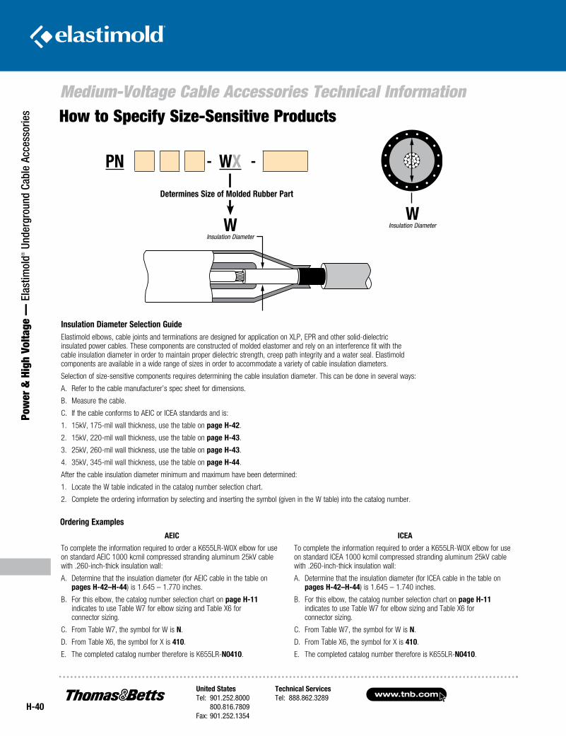
www.tnb.comUnited StatesTel: 901.252.8000 800.816.7809Fax: 901.252.1354
Technical ServicesTel: 888.862.3289
H-40
Medium-Voltage Cable Accessories Technical Information
Pow
er &
Hig
h Vo
ltage
— E
last
imol
d® U
nder
grou
nd C
able
Acc
esso
ries
Insulation Diameter Selection GuideElastimold elbows, cable joints and terminations are designed for application on XLP, EPR and other solid-dielectric insulated power cables. These components are constructed of molded elastomer and rely on an interference fit with the cable insulation diameter in order to maintain proper dielectric strength, creep path integrity and a water seal. Elastimold components are available in a wide range of sizes in order to accommodate a variety of cable insulation diameters.
Selection of size-sensitive components requires determining the cable insulation diameter. This can be done in several ways:
A. Refer to the cable manufacturer’s spec sheet for dimensions.
B. Measure the cable.
C. If the cable conforms to AEIC or ICEA standards and is:
1. 15kV, 175-mil wall thickness, use the table on page H-42.
2. 15kV, 220-mil wall thickness, use the table on page H-43.
3. 25kV, 260-mil wall thickness, use the table on page H-43.
4. 35kV, 345-mil wall thickness, use the table on page H-44.
After the cable insulation diameter minimum and maximum have been determined:
1. Locate the W table indicated in the catalog number selection chart.
2. Complete the ordering information by selecting and inserting the symbol (given in the W table) into the catalog number.
‘W’CABLE
INSULATIONDIAMETER
Ordering Examples
AEIC
To complete the information required to order a K655LR-W0X elbow for use on standard AEIC 1000 kcmil compressed stranding aluminum 25kV cable with .260-inch-thick insulation wall:
A. Determine that the insulation diameter (for AEIC cable in the table on pages H-42–H-44) is 1.645 – 1.770 inches.
B. For this elbow, the catalog number selection chart on page H-11 indicates to use Table W7 for elbow sizing and Table X6 for connector sizing.
C. From Table W7, the symbol for W is N.
D. From Table X6, the symbol for X is 410.
E. The completed catalog number therefore is K655LR-N0410.
ICEA
To complete the information required to order a K655LR-W0X elbow for use on standard ICEA 1000 kcmil compressed stranding aluminum 25kV cable with .260-inch-thick insulation wall:
A. Determine that the insulation diameter (for ICEA cable in the table on pages H-42–H-44) is 1.645 – 1.740 inches.
B. For this elbow, the catalog number selection chart on page H-11 indicates to use Table W7 for elbow sizing and Table X6 for connector sizing.
C. From Table W7, the symbol for W is N.
D. From Table X6, the symbol for X is 410.
E. The completed catalog number therefore is K655LR-N0410.
How to Specify Size-Sensitive Products
‘W’INSULATIONDIAMETER
Determines Size of Molded Rubber PartDetermines Size of Molded Rubber Part
W Insulation Diameter
W Insulation Diameter
PN - WX -
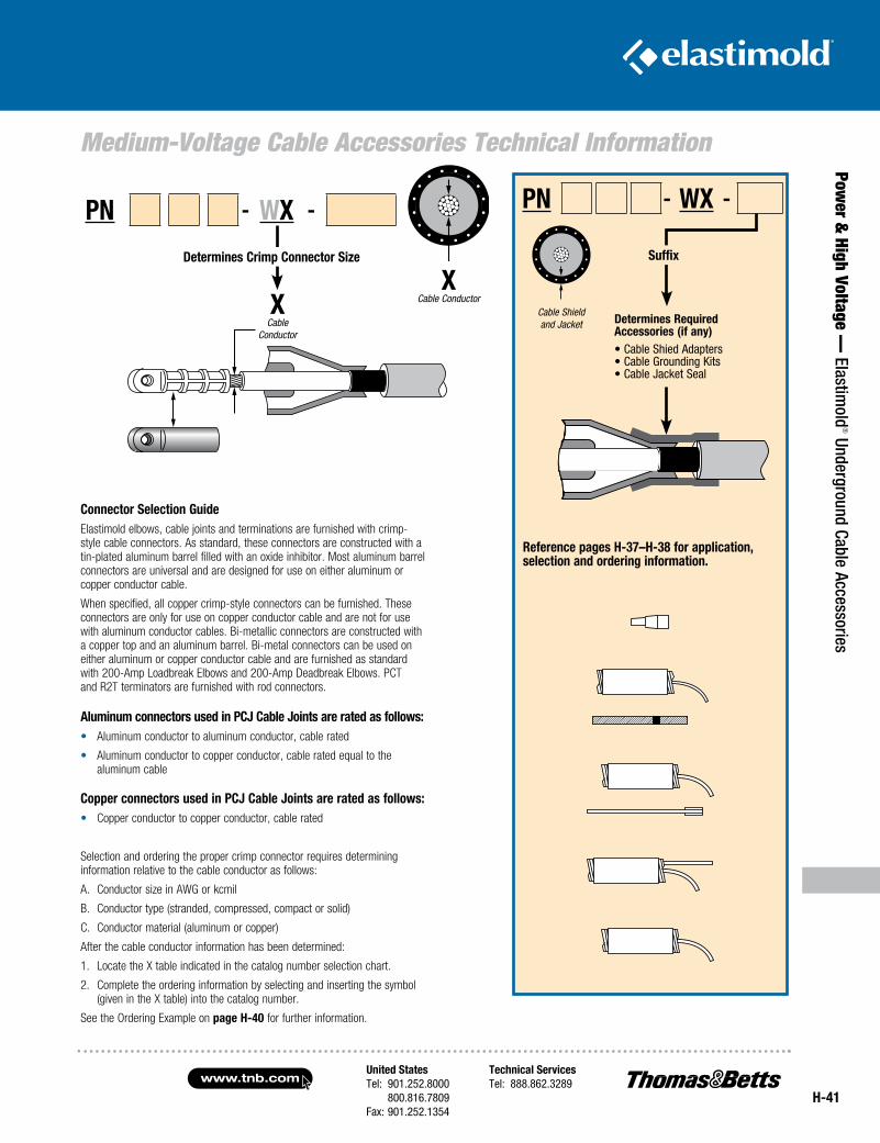
United StatesTel: 901.252.8000 800.816.7809Fax: 901.252.1354
Technical ServicesTel: 888.862.3289www.tnb.com
H-41
Medium-Voltage Cable Accessories Technical Information
Power &
High Voltage — Elastim
old® Underground Cable Accessories
‘X’CABLE
CONDUCTOR
Reference pages H-37–H-38 for application, selection and ordering information.
Connector Selection GuideElastimold elbows, cable joints and terminations are furnished with crimp- style cable connectors. As standard, these connectors are constructed with a tin-plated aluminum barrel filled with an oxide inhibitor. Most aluminum barrel connectors are universal and are designed for use on either aluminum or copper conductor cable.
When specified, all copper crimp-style connectors can be furnished. These connectors are only for use on copper conductor cable and are not for use with aluminum conductor cables. Bi-metallic connectors are constructed with a copper top and an aluminum barrel. Bi-metal connectors can be used on either aluminum or copper conductor cable and are furnished as standard with 200-Amp Loadbreak Elbows and 200-Amp Deadbreak Elbows. PCT and R2T terminators are furnished with rod connectors.
Aluminum connectors used in PCJ Cable Joints are rated as follows: • Aluminum conductor to aluminum conductor, cable rated
• Aluminum conductor to copper conductor, cable rated equal to the aluminum cable
Copper connectors used in PCJ Cable Joints are rated as follows: • Copper conductor to copper conductor, cable rated
Selection and ordering the proper crimp connector requires determining information relative to the cable conductor as follows:
A. Conductor size in AWG or kcmil
B. Conductor type (stranded, compressed, compact or solid)
C. Conductor material (aluminum or copper)
After the cable conductor information has been determined:
1. Locate the X table indicated in the catalog number selection chart.
2. Complete the ordering information by selecting and inserting the symbol (given in the X table) into the catalog number.
See the Ordering Example on page H-40 for further information.
X Cable Conductor
Determines Crimp Connector Size
‘X’CABLE
CONDUCTOR
Determines Crimp Connector Size
PN - WX -
X Cable
Conductor
‘Suffix’
Determines Required Accessories (if any)
• Cable Shield Adapters• Cable Grounding Kits• Cable Jacket Seal
Suffix
PN - WX -
Determines Required Accessories (if any)• Cable Shied Adapters• Cable Grounding Kits• Cable Jacket Seal
CABLE SHIELDAND JACKETCable Shield
and Jacket
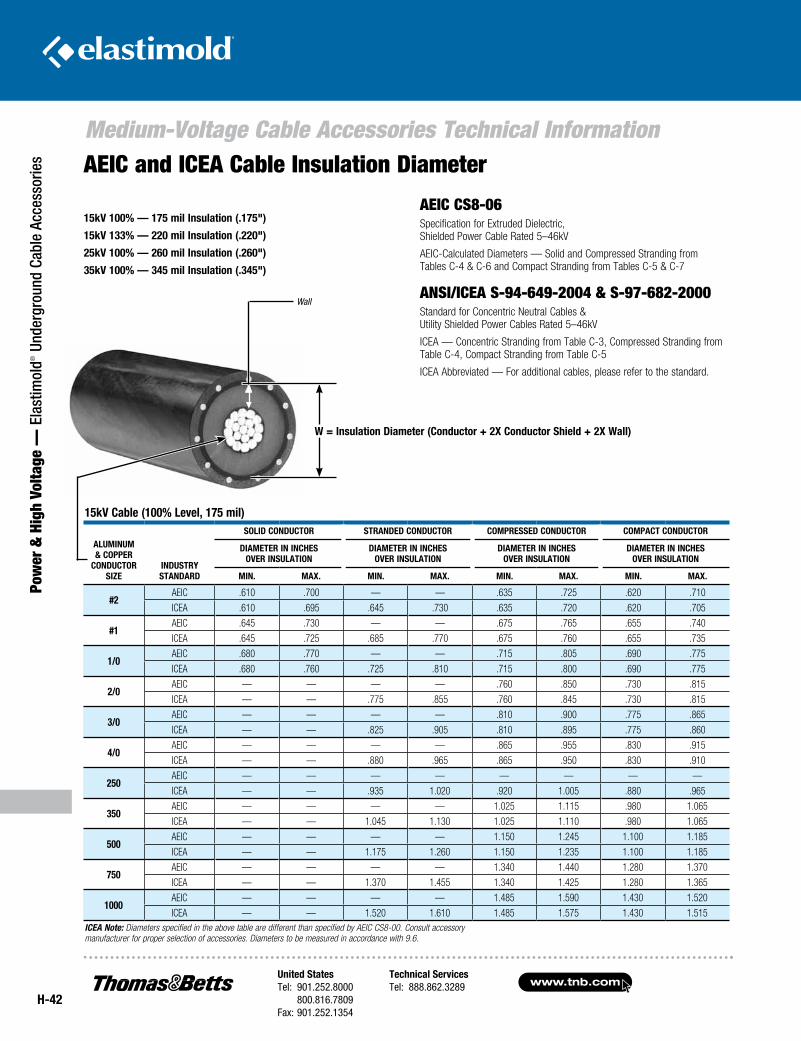
www.tnb.comUnited StatesTel: 901.252.8000 800.816.7809Fax: 901.252.1354
Technical ServicesTel: 888.862.3289
H-42
Medium-Voltage Cable Accessories Technical Information
Pow
er &
Hig
h Vo
ltage
— E
last
imol
d® U
nder
grou
nd C
able
Acc
esso
ries AEIC and ICEA Cable Insulation Diameter
W = Insulation Diameter (Conductor + 2X Conductor Shield + 2X Wall)
15kV 100% — 175 mil Insulation (.175")
15kV 133% — 220 mil Insulation (.220")
25kV 100% — 260 mil Insulation (.260")
35kV 100% — 345 mil Insulation (.345")
Wall
AEIC CS8-06Specification for Extruded Dielectric, Shielded Power Cable Rated 5–46kV
AEIC-Calculated Diameters — Solid and Compressed Stranding from Tables C-4 & C-6 and Compact Stranding from Tables C-5 & C-7
ANSI/ICEA S-94-649-2004 & S-97-682-2000Standard for Concentric Neutral Cables & Utility Shielded Power Cables Rated 5–46kV
ICEA — Concentric Stranding from Table C-3, Compressed Stranding from Table C-4, Compact Stranding from Table C-5
ICEA Abbreviated — For additional cables, please refer to the standard.
15kV Cable (100% Level, 175 mil)
ALumInum & Copper
ConDuCtor SIze
InDuStry StAnDArD
SoLID ConDuCtor StrAnDeD ConDuCtor CompreSSeD ConDuCtor CompACt ConDuCtor
DIAmeter In InCHeSoVer InSuLAtIon
DIAmeter In InCHeSoVer InSuLAtIon
DIAmeter In InCHeSoVer InSuLAtIon
DIAmeter In InCHeSoVer InSuLAtIon
mIn. mAX. mIn. mAX. mIn. mAX. mIn. mAX.
#2AEIC .610 .700 — — .635 .725 .620 .710
ICEA .610 .695 .645 .730 .635 .720 .620 .705
#1AEIC .645 .730 — — .675 .765 .655 .740
ICEA .645 .725 .685 .770 .675 .760 .655 .735
1/0AEIC .680 .770 — — .715 .805 .690 .775
ICEA .680 .760 .725 .810 .715 .800 .690 .775
2/0AEIC — — — — .760 .850 .730 .815
ICEA — — .775 .855 .760 .845 .730 .815
3/0AEIC — — — — .810 .900 .775 .865
ICEA — — .825 .905 .810 .895 .775 .860
4/0AEIC — — — — .865 .955 .830 .915
ICEA — — .880 .965 .865 .950 .830 .910
250AEIC — — — — — — — —
ICEA — — .935 1.020 .920 1.005 .880 .965
350AEIC — — — — 1.025 1.115 .980 1.065
ICEA — — 1.045 1.130 1.025 1.110 .980 1.065
500AEIC — — — — 1.150 1.245 1.100 1.185
ICEA — — 1.175 1.260 1.150 1.235 1.100 1.185
750AEIC — — — — 1.340 1.440 1.280 1.370
ICEA — — 1.370 1.455 1.340 1.425 1.280 1.365
1000AEIC — — — — 1.485 1.590 1.430 1.520
ICEA — — 1.520 1.610 1.485 1.575 1.430 1.515ICEA Note: Diameters specified in the above table are different than specified by AEIC CS8-00. Consult accessory manufacturer for proper selection of accessories. Diameters to be measured in accordance with 9.6.
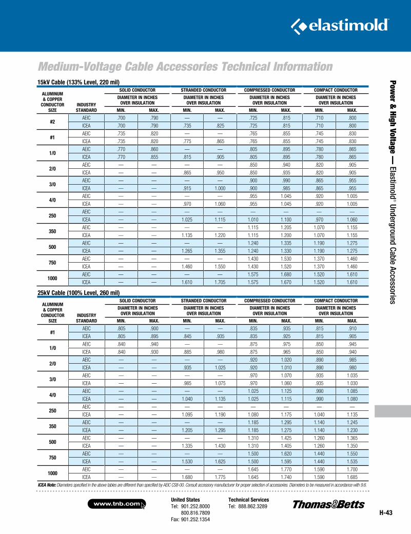
United StatesTel: 901.252.8000 800.816.7809Fax: 901.252.1354
Technical ServicesTel: 888.862.3289www.tnb.com
H-43
Medium-Voltage Cable Accessories Technical Information
Power &
High Voltage — Elastim
old® Underground Cable Accessories
15kV Cable (133% Level, 220 mil)
ALumInum & Copper
ConDuCtor SIze
InDuStry StAnDArD
SoLID ConDuCtor StrAnDeD ConDuCtor CompreSSeD ConDuCtor CompACt ConDuCtor
DIAmeter In InCHeSoVer InSuLAtIon
DIAmeter In InCHeSoVer InSuLAtIon
DIAmeter In InCHeSoVer InSuLAtIon
DIAmeter In InCHeSoVer InSuLAtIon
mIn. mAX. mIn. mAX. mIn. mAX. mIn. mAX.
#2AEIC .700 .790 — — .725 .815 .710 .800
ICEA .700 .790 .735 .825 .725 .815 .710 .800
#1AEIC .735 .820 — — .765 .855 .745 .830
ICEA .735 .820 .775 .865 .765 .855 .745 .830
1/0AEIC .770 .860 — — .805 .895 .780 .865
ICEA .770 .855 .815 .905 .805 .895 .780 .865
2/0AEIC — — — — .850 .940 .820 .905
ICEA — — .865 .950 .850 .935 .820 .905
3/0AEIC — — — — .900 .990 .865 .955
ICEA — — .915 1.000 .900 .985 .865 .955
4/0AEIC — — — — .955 1.045 .920 1.005
ICEA — — .970 1.060 .955 1.045 .920 1.005
250AEIC — — — — — — — —
ICEA — — 1.025 1.115 1.010 1.100 .970 1.060
350AEIC — — — — 1.115 1.205 1.070 1.155
ICEA — — 1.135 1.220 1.115 1.200 1.070 1.155
500AEIC — — — — 1.240 1.335 1.190 1.275
ICEA — — 1.265 1.355 1.240 1.330 1.190 1.275
750AEIC — — — — 1.430 1.530 1.370 1.460
ICEA — — 1.460 1.550 1.430 1.520 1.370 1.460
1000AEIC — — — — 1.575 1.680 1.520 1.610
ICEA — — 1.610 1.705 1.575 1.670 1.520 1.610
25kV Cable (100% Level, 260 mil)
ALumInum & Copper
ConDuCtor SIze
InDuStry StAnDArD
SoLID ConDuCtor StrAnDeD ConDuCtor CompreSSeD ConDuCtor CompACt ConDuCtor
DIAmeter In InCHeSoVer InSuLAtIon
DIAmeter In InCHeSoVer InSuLAtIon
DIAmeter In InCHeSoVer InSuLAtIon
DIAmeter In InCHeSoVer InSuLAtIon
mIn. mAX. mIn. mAX. mIn. mAX. mIn. mAX.
#1AEIC .805 .900 — — .835 .935 .815 .910
ICEA .805 .895 .845 .935 .835 .925 .815 .905
1/0AEIC .840 .940 — — .875 .975 .850 .945
ICEA .840 .930 .885 .980 .875 .965 .850 .940
2/0AEIC — — — — .920 1.020 .890 .985
ICEA — — .935 1.025 .920 1.010 .890 .980
3/0AEIC — — — — .970 1.070 .935 1.035
ICEA — — .985 1.075 .970 1.060 .935 1.030
4/0AEIC — — — — 1.025 1.125 .990 1.085
ICEA — — 1.040 1.135 1.025 1.115 .990 1.080
250AEIC — — — — — — — —
ICEA — — 1.095 1.190 1.080 1.175 1.040 1.135
350AEIC — — — — 1.185 1.295 1.140 1.245
ICEA — — 1.205 1.295 1.185 1.275 1.140 1.230
500AEIC — — — — 1.310 1.425 1.260 1.365
ICEA — — 1.335 1.430 1.310 1.405 1.260 1.350
750AEIC — — — — 1.500 1.620 1.440 1.550
ICEA — — 1.530 1.625 1.500 1.595 1.440 1.535
1000AEIC — — — — 1.645 1.770 1.590 1.700
ICEA — — 1.680 1.775 1.645 1.740 1.590 1.685ICEA Note: Diameters specified in the above tables are different than specified by AEIC CS8-00. Consult accessory manufacturer for proper selection of accessories. Diameters to be measured in accordance with 9.6.
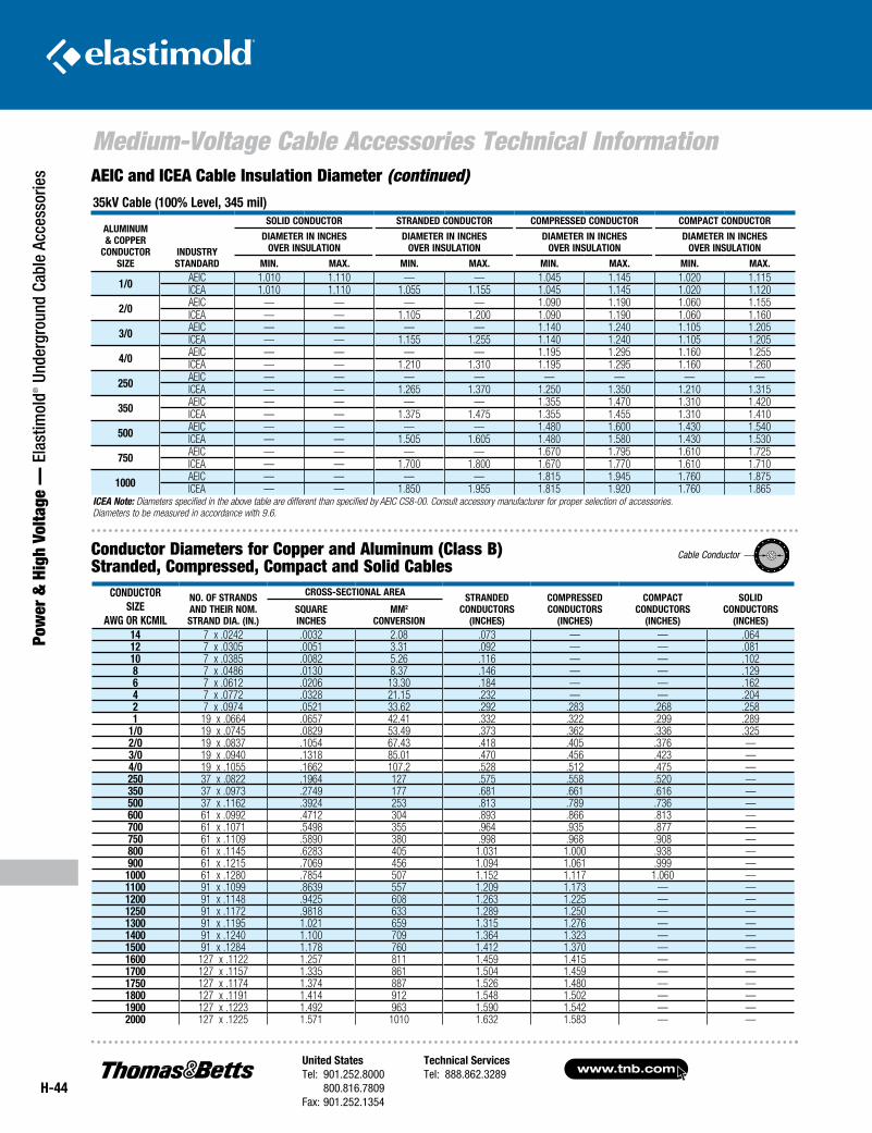
www.tnb.comUnited StatesTel: 901.252.8000 800.816.7809Fax: 901.252.1354
Technical ServicesTel: 888.862.3289
H-44
Medium-Voltage Cable Accessories Technical Information
Pow
er &
Hig
h Vo
ltage
— E
last
imol
d® U
nder
grou
nd C
able
Acc
esso
ries AEIC and ICEA Cable Insulation Diameter (continued)
Conductor Diameters for Copper and Aluminum (Class B) Stranded, Compressed, Compact and Solid Cables
ConduCtorSize
AWG or kCmil
no. of StrAndSAnd tHeir nom.StrAnd diA. (in.)
CroSS-SeCtionAl AreA StrAndedConduCtorS
(inCHeS)
CompreSSedConduCtorS
(inCHeS)
CompACtConduCtorS
(inCHeS)
SolidConduCtorS
(inCHeS)SquAreinCHeS
mm2
ConverSion14 7 x .0242 .0032 2.08 .073 — — .06412 7 x .0305 .0051 3.31 .092 — — .08110 7 x .0385 .0082 5.26 .116 — — .1028 7 x .0486 .0130 8.37 .146 — — .1296 7 x .0612 .0206 13.30 .184 — — .1624 7 x .0772 .0328 21.15 .232 — — .2042 7 x .0974 .0521 33.62 .292 .283 .268 .2581 19 x .0664 .0657 42.41 .332 .322 .299 .289
1/0 19 x .0745 .0829 53.49 .373 .362 .336 .3252/0 19 x .0837 .1054 67.43 .418 .405 .376 —3/0 19 x .0940 .1318 85.01 .470 .456 .423 —4/0 19 x .1055 .1662 107.2 .528 .512 .475 —250 37 x .0822 .1964 127 .575 .558 .520 —350 37 x .0973 .2749 177 .681 .661 .616 —500 37 x .1162 .3924 253 .813 .789 .736 —600 61 x .0992 .4712 304 .893 .866 .813 —700 61 x .1071 .5498 355 .964 .935 .877 —750 61 x .1109 .5890 380 .998 .968 .908 —800 61 x .1145 .6283 405 1.031 1.000 .938 —900 61 x .1215 .7069 456 1.094 1.061 .999 —
1000 61 x .1280 .7854 507 1.152 1.117 1.060 —1100 91 x .1099 .8639 557 1.209 1.173 — —1200 91 x .1148 .9425 608 1.263 1.225 — —1250 91 x .1172 .9818 633 1.289 1.250 — —1300 91 x .1195 1.021 659 1.315 1.276 — —1400 91 x .1240 1.100 709 1.364 1.323 — —1500 91 x .1284 1.178 760 1.412 1.370 — —1600 127 x .1122 1.257 811 1.459 1.415 — —1700 127 x .1157 1.335 861 1.504 1.459 — —1750 127 x .1174 1.374 887 1.526 1.480 — —1800 127 x .1191 1.414 912 1.548 1.502 — —1900 127 x .1223 1.492 963 1.590 1.542 — —2000 127 x .1225 1.571 1010 1.632 1.583 — —
CA
BLE
CO
ND
UC
TOR
35kv Cable (100% level, 345 mil)
Aluminum & Copper
ConduCtor Size
induStry StAndArd
Solid ConduCtor StrAnded ConduCtor CompreSSed ConduCtor CompACt ConduCtor
diAmeter in inCHeSover inSulAtion
diAmeter in inCHeSover inSulAtion
diAmeter in inCHeSover inSulAtion
diAmeter in inCHeSover inSulAtion
min. mAx. min. mAx. min. mAx. min. mAx.
1/0 AEIC 1.010 1.110 — — 1.045 1.145 1.020 1.115ICEA 1.010 1.110 1.055 1.155 1.045 1.145 1.020 1.120
2/0 AEIC — — — — 1.090 1.190 1.060 1.155ICEA — — 1.105 1.200 1.090 1.190 1.060 1.160
3/0 AEIC — — — — 1.140 1.240 1.105 1.205ICEA — — 1.155 1.255 1.140 1.240 1.105 1.205
4/0 AEIC — — — — 1.195 1.295 1.160 1.255ICEA — — 1.210 1.310 1.195 1.295 1.160 1.260
250 AEIC — — — — — — — —ICEA — — 1.265 1.370 1.250 1.350 1.210 1.315
350 AEIC — — — — 1.355 1.470 1.310 1.420ICEA — — 1.375 1.475 1.355 1.455 1.310 1.410
500 AEIC — — — — 1.480 1.600 1.430 1.540ICEA — — 1.505 1.605 1.480 1.580 1.430 1.530
750 AEIC — — — — 1.670 1.795 1.610 1.725ICEA — — 1.700 1.800 1.670 1.770 1.610 1.710
1000 AEIC — — — — 1.815 1.945 1.760 1.875ICEA — — 1.850 1.955 1.815 1.920 1.760 1.865
ICEA Note: Diameters specified in the above table are different than specified by AEIC CS8-00. Consult accessory manufacturer for proper selection of accessories. Diameters to be measured in accordance with 9.6.
Cable Conductor
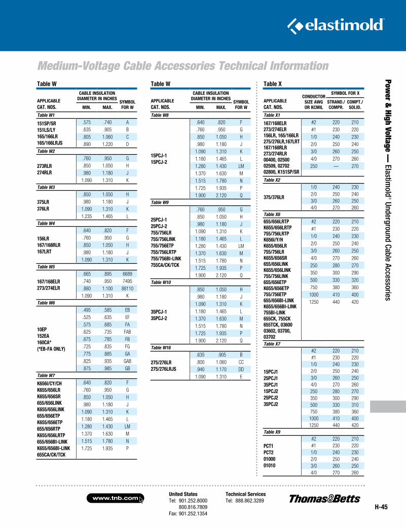
United StatesTel: 901.252.8000 800.816.7809Fax: 901.252.1354
Technical ServicesTel: 888.862.3289www.tnb.com
H-45
Medium-Voltage Cable Accessories Technical Information
Power &
High Voltage — Elastim
old® Underground Cable Accessories
table W
AppliCAbleCAt. noS.
CAble inSulAtion diAmeter in inCHeS
Symbolfor Wmin. mAx.
Table W1
151Sp/Sr151lS/ly165/166lr165/166lrJS
.575 .740 A
.635 .905 B
.805 1.060 C
.890 1.220 DTable W2
273rlr274rlr
.760 .950 G
.850 1.050 H
.980 1.180 J1.090 1.310 K
Table W3
375lr376lr
.850 1.050 H
.980 1.180 J1.090 1.310 K1.235 1.465 L
Table W4
156lr167/168rlr167lrt
.640 .820 F
.760 .950 G
.850 1.050 H
.980 1.180 J1.090 1.310 K
Table W5
167/168elr273/274elr
.665 .895 6689
.740 .950 7495
.880 1.100 881101.090 1.310 K
Table W6
10ep152eA160CA*(*eb-fA only)
.495 .585 EB
.525 .635 EF
.575 .685 FA
.625 .735 FAB
.675 .785 FB
.725 .835 FG
.775 .885 GA
.825 .935 GAB
.875 .985 GBTable W7
k656i/Cy/CHk655/656lrk655/656Sr655/656linkk655/656link655/656etpk655/656etp655/656rtpk655/656lrtp655/656bi-linkk655/656bi-link655CA/Ck/tCk
.640 .820 F
.760 .950 G
.850 1.050 H
.980 1.180 J1.090 1.310 K1.180 1.465 L1.280 1.430 LM1.370 1.630 M1.515 1.780 N1.725 1.935 P
table W
AppliCAbleCAt. noS.
CAble inSulAtion diAmeter in inCHeS
Symbolfor Wmin. mAx.
Table W8
15pCJ-115pCJ-2
.640 .820 F
.760 .950 G
.850 1.050 H
.980 1.180 J1.090 1.310 K1.180 1.465 L1.280 1.430 LM1.370 1.630 M1.515 1.780 N1.725 1.935 P1.900 2.120 Q
Table W9
25pCJ-125pCJ-2755/756lr755/756link755/756etp755/756lrtp755/756bi-link755CA/Ck/tCk
.760 .950 G
.850 1.050 H
.980 1.180 J1.090 1.310 K1.180 1.465 L1.280 1.430 LM1.370 1.630 M1.515 1.780 N1.725 1.935 P1.900 2.120 Q
Table W10
35pCJ-135pCJ-2
.850 1.050 H
.980 1.180 J1.090 1.310 K1.180 1.465 L1.370 1.630 M1.515 1.780 N1.725 1.935 P1.900 2.120 Q
Table W16
275/276lr275/276lrJS
.635 .905 B
.800 1.060 CC
.940 1.170 DD1.090 1.310 E
table x
AppliCAbleCAt. noS.
ConduCtorSize AWGor kCmil
Symbol for x
StrAnd./Compr.
Compt./Solid.
Table X1
167/168elr273/274elr156lr, 165/166lr275/276lr,167lrt 167/168rlr273/274rlr00400, 0250002509, 0270202800, k151Sp/Sr
#2 220 210#1 230 2201/0 240 2302/0 250 2403/0 260 2504/0 270 260250 — 270
Table X2
375/376lr
1/0 240 2302/0 250 2403/0 260 2504/0 270 260
Table X6
655/656lrtpk655/656lrtp755/756lrtpk656i/y/Hk655/656lr755/756lrk655/656Sr655/656linkk655/656link755/756link655/656etpk655/656etp755/756etp655/656bi-linkk655/656bi-link755bi-link655Ck, 755Ck655tCk, 0360003602, 03700, 03702
#2 220 210#1 230 2201/0 240 2302/0 250 2403/0 260 2504/0 270 260250 280 270350 300 290500 330 320750 380 3601000 410 4001250 440 420
Table X7
15pCJ125pCJ135pCJ115pCJ225pCJ235pCJ2
#2 220 210#1 230 2201/0 240 2302/0 250 2403/0 260 2504/0 270 260250 280 270350 300 290500 330 310750 380 3601000 410 4001250 440 420
Table X9
pCt1pCt20100001010
#2 220 210#1 230 2201/0 240 2302/0 250 2403/0 260 2504/0 270 260
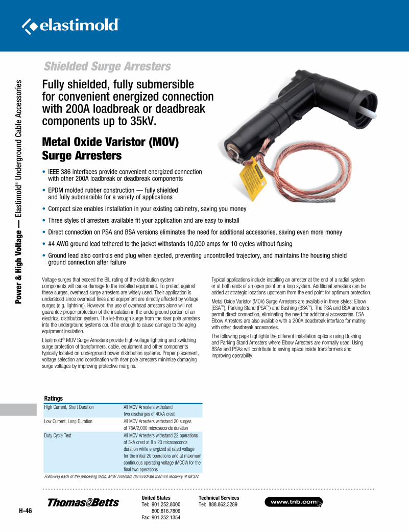
www.tnb.comUnited StatesTel: 901.252.8000 800.816.7809Fax: 901.252.1354
Technical ServicesTel: 888.862.3289
H-46
Shielded Surge Arresters
Pow
er &
Hig
h Vo
ltage
— E
last
imol
d® U
nder
grou
nd C
able
Acc
esso
ries
• IEEE 386 interfaces provide convenient energized connection with other 200A loadbreak or deadbreak components
• EPDM molded rubber construction — fully shielded and fully submersible for a variety of applications
• Compact size enables installation in your existing cabinetry, saving you money
• Three styles of arresters available fit your application and are easy to install
• Direct connection on PSA and BSA versions eliminates the need for additional accessories, saving even more money
• #4 AWG ground lead tethered to the jacket withstands 10,000 amps for 10 cycles without fusing
• Ground lead also controls end plug when ejected, preventing uncontrolled trajectory, and maintains the housing shield ground connection after failure
RatingsHigh Current, Short Duration All MOV Arresters withstand
two discharges of 40kA crestLow Current, Long Duration All MOV Arresters withstand 20 surges
of 75A/2,000 microseconds durationDuty Cycle Test
All MOV Arresters withstand 22 operations of 5kA crest at 8 x 20 microseconds duration while energized at rated voltage for the initial 20 operations and at maximum continuous operating voltage (MCOV) for the final two operations
Following each of the preceding tests, MOV Arresters demonstrate thermal recovery at MCOV.
Voltage surges that exceed the BIL rating of the distribution system components will cause damage to the installed equipment. To protect against these surges, overhead surge arresters are widely used. Their application is understood since overhead lines and equipment are directly affected by voltage surges (e.g. lightning). However, the use of overhead arresters alone will not guarantee proper protection of the insulation in the underground portion of an electrical distribution system. The let-through surge from the riser pole arresters into the underground systems could be enough to cause damage to the aging equipment insulation.
Elastimold® MOV Surge Arresters provide high-voltage lightning and switching surge protection of transformers, cable, equipment and other components typically located on underground power distribution systems. Proper placement, voltage selection and coordination with riser pole arresters minimize damaging surge voltages by improving protective margins.
Typical applications include installing an arrester at the end of a radial system or at both ends of an open point on a loop system. Additional arresters can be added at strategic locations upstream from the end point for optimum protection.
Metal Oxide Varistor (MOV) Surge Arresters are available in three styles: Elbow (ESA™), Parking Stand (PSA™) and Bushing (BSA™). The PSA and BSA arresters permit direct connection, eliminating the need for additional accessories. ESA Elbow Arresters are also available with a 200A deadbreak interface for mating with other deadbreak accessories.
The following page highlights the different installation options using Bushing and Parking Stand Arresters where Elbow Arresters are normally used. Using BSAs and PSAs will contribute to saving space inside transformers and improving operability.
Fully shielded, fully submersible for convenient energized connection with 200A loadbreak or deadbreak components up to 35kV.
Metal Oxide Varistor (MOV) Surge Arresters
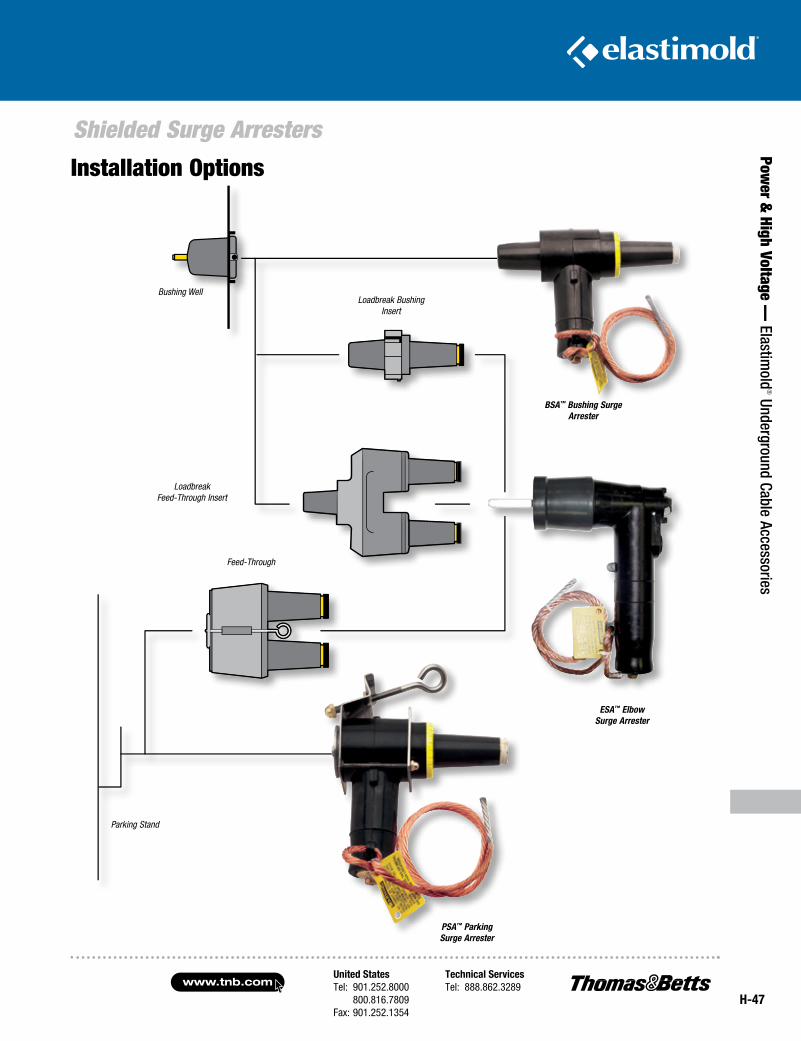
United StatesTel: 901.252.8000 800.816.7809Fax: 901.252.1354
Technical ServicesTel: 888.862.3289www.tnb.com
H-47
Shielded Surge Arresters
Power &
High Voltage — Elastim
old® Underground Cable Accessories
PSA™ Parking Surge Arrester
BSA™ Bushing Surge Arrester
Loadbreak Bushing Insert
LoadbreakFeed-Through Insert
Parking Stand
Feed-Through
Bushing Well
ESA™ Elbow Surge Arrester
Installation Options
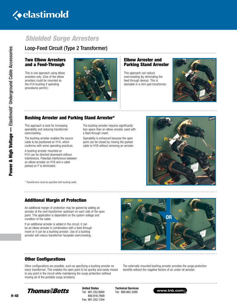
www.tnb.comUnited StatesTel: 901.252.8000 800.816.7809Fax: 901.252.1354
Technical ServicesTel: 888.862.3289
H-48
Shielded Surge Arresters
Pow
er &
Hig
h Vo
ltage
— E
last
imol
d® U
nder
grou
nd C
able
Acc
esso
ries
An additional margin of protection may be gained by adding an arrester at the next transformer upstream on each side of the open point. This application is dependent on the system voltage and condition of the cable.
If an additional arrester is added in the circuit, it can be an elbow arrester in combination with a feed-through insert or it can be a bushing arrester. Use of a bushing arrester will reduce transformer faceplate overcrowding.
Other configurations are possible, such as specifying a bushing arrester on every transformer. This enables the open point to be quickly and easily moved to any point in the circuit while maintaining the surge protection (without moving all of the portable surge arresters).
The externally mounted bushing arrester provides the surge protection benefits without the negative factors of an under-oil arrester.
This approach is best for increasing operability and reducing transformer overcrowding.
The bushing arrester enables the source cable to be positioned on H1A, which conforms with some operating practices.
A bushing arrester mounted on H1A can be directed downward without interference. Potential interference between an elbow arrester on H1B and a cable parked on P is eliminated.
The bushing arrester requires significantly less space than an elbow arrester used with a feed-through insert.
Operability is enhanced because the open point can be closed by moving the parked cable to H1B without removing an arrester.
* Transformers must be specified with bushing wells.
Bushing Arrester and Parking Stand Arrester*
Additional Margin of Protection
Other Configurations
Elbow Arrester and Parking Stand Arrester
This approach can reduce overcrowding (by eliminating the feed-through device). This is desirable in a mini-pad transformer.
Loop-Feed Circuit (Type 2 Transformer)
Two Elbow Arresters and a Feed-Through
This is one approach using elbow arresters only. (One of the elbow arresters could be mounted on the H1A bushing if operating procedures permit.)
OR
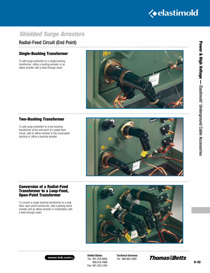
United StatesTel: 901.252.8000 800.816.7809Fax: 901.252.1354
Technical ServicesTel: 888.862.3289www.tnb.com
H-49
Shielded Surge Arresters
Power &
High Voltage — Elastim
old® Underground Cable Accessories
Single-Bushing Transformer
To add surge protection to a single-bushing transformer, utilize a bushing arrester or an elbow arrester with a feed-through insert.
Two-Bushing Transformer
To add surge protection to a two-bushing transformer at the end point of a radial-feed circuit, add an elbow arrester to the unoccupied bushing or utilize a bushing arrester.
Conversion of a Radial-Feed Transformer to a Loop-Feed, Open-Point Transformer
To convert a single-bushing transformer to a loop-feed, open-point transformer, add a parking stand arrester and an elbow arrester in combination with a feed-through insert.
Radial-Feed Circuit (End Point)
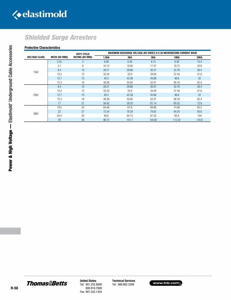
www.tnb.comUnited StatesTel: 901.252.8000 800.816.7809Fax: 901.252.1354
Technical ServicesTel: 888.862.3289
H-50
Shielded Surge Arresters
Pow
er &
Hig
h Vo
ltage
— E
last
imol
d® U
nder
grou
nd C
able
Acc
esso
ries Protective Characteristics
VOLTAGE CLAss MCOV (KV RMs)DUTY CYCLE
RATinG (KV RMs)
MAXiMUM DisCHARGE VOLTAGE (KV CREsT) 8 X 20 MiCROsECOnD CURREnT WAVE
1.5KA 3KA 5KA 10KA 20KA
15kV
2.55 3 8.06 8.48 8.74 9.36 10.45.1 6 16.12 16.95 17.47 18.72 20.88.4 10 28.21 29.66 30.57 32.76 36.410.2 12 32.24 33.9 34.94 37.44 41.612.7 15 40.3 42.38 43.68 46.8 5215.3 18 48.36 50.85 52.41 56.16 62.4
25kV
8.4 10 28.21 29.66 30.57 32.76 36.410.2 12 32.24 33.9 34.94 37.44 41.612.7 15 40.3 42.38 43.68 46.8 5215.3 18 48.36 50.85 52.41 56.16 62.417 21 56.42 59.32 61.14 65.52 72.8
38kV
19.5 24 64.48 67.8 69.88 74.88 83.222 27 72.54 76.28 78.62 84.24 93.6
24.4 30 80.6 84.75 87.35 93.6 10429 36 96.72 101.7 104.82 112.32 124.8
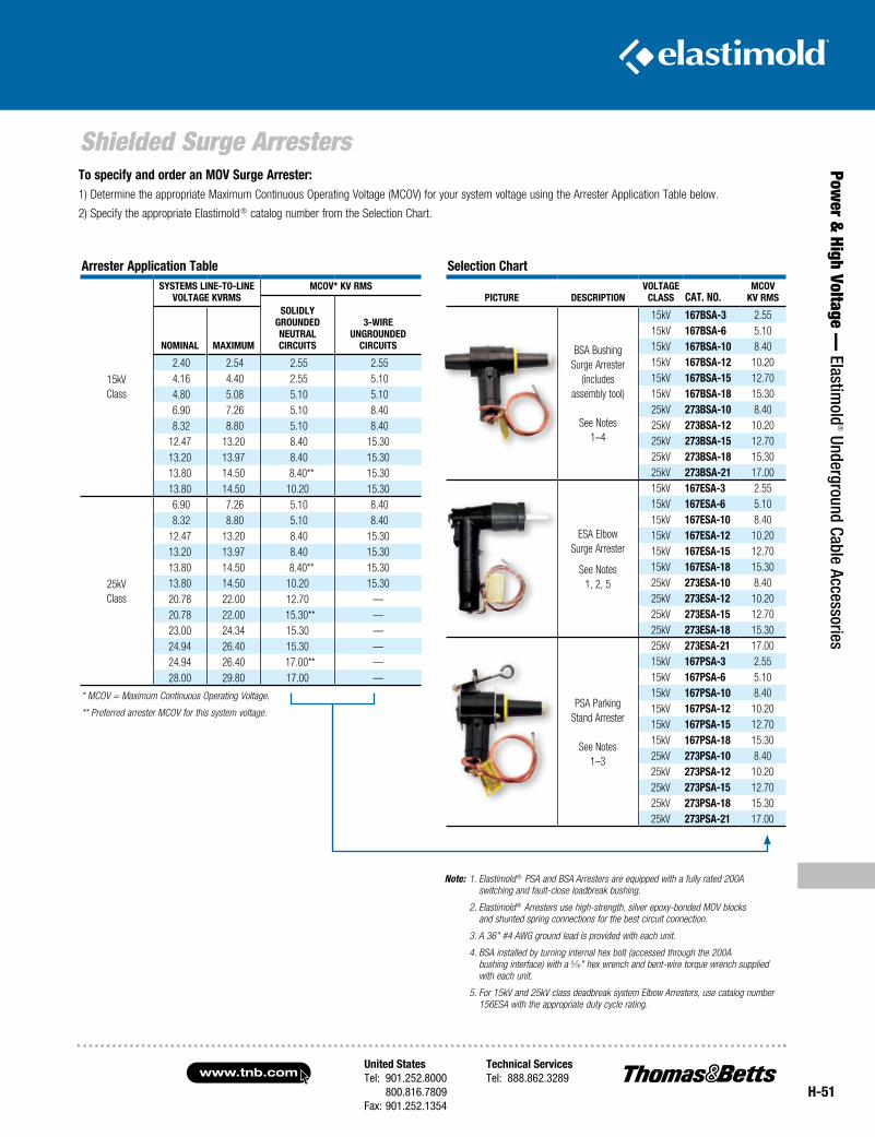
United StatesTel: 901.252.8000 800.816.7809Fax: 901.252.1354
Technical ServicesTel: 888.862.3289www.tnb.com
H-51
Shielded Surge Arresters
Power &
High Voltage — Elastim
old® Underground Cable Accessories
selection Chart
PiCTURE DEsCRiPTiOnVOLTAGE
CLAss CAT. nO.MCOV
KV RMs
BSA BushingSurge Arrester
(includes assembly tool)
See Notes1–4
15kV 167BsA-3 2.5515kV 167BsA-6 5.1015kV 167BsA-10 8.4015kV 167BsA-12 10.2015kV 167BsA-15 12.7015kV 167BsA-18 15.3025kV 273BsA-10 8.4025kV 273BsA-12 10.2025kV 273BsA-15 12.7025kV 273BsA-18 15.3025kV 273BsA-21 17.00
ESA ElbowSurge Arrester
See Notes1, 2, 5
15kV 167EsA-3 2.5515kV 167EsA-6 5.1015kV 167EsA-10 8.4015kV 167EsA-12 10.2015kV 167EsA-15 12.7015kV 167EsA-18 15.3025kV 273EsA-10 8.4025kV 273EsA-12 10.2025kV 273EsA-15 12.7025kV 273EsA-18 15.30
PSA ParkingStand Arrester
See Notes1–3
25kV 273EsA-21 17.0015kV 167PsA-3 2.5515kV 167PsA-6 5.1015kV 167PsA-10 8.4015kV 167PsA-12 10.2015kV 167PsA-15 12.7015kV 167PsA-18 15.3025kV 273PsA-10 8.4025kV 273PsA-12 10.2025kV 273PsA-15 12.7025kV 273PsA-18 15.3025kV 273PsA-21 17.00
Arrester Application Table
15kVClass
sYsTEMs LinE-TO-LinEVOLTAGE KVRMs
MCOV* KV RMs
sOLiDLYGROUnDEDnEUTRALCiRCUiTs
3-WiREUnGROUnDED
CiRCUiTsnOMinAL MAXiMUM
2.40 2.54 2.55 2.55 4.16 4.40 2.55 5.10 4.80 5.08 5.10 5.10 6.90 7.26 5.10 8.40 8.32 8.80 5.10 8.4012.47 13.20 8.40 15.3013.20 13.97 8.40 15.3013.80 14.50 8.40** 15.3013.80 14.50 10.20 15.30
25kVClass
6.90 7.26 5.10 8.40 8.32 8.80 5.10 8.4012.47 13.20 8.40 15.3013.20 13.97 8.40 15.3013.80 14.50 8.40** 15.3013.80 14.50 10.20 15.3020.78 22.00 12.70 —20.78 22.00 15.30** —23.00 24.34 15.30 —24.94 26.40 15.30 —24.94 26.40 17.00** —28.00 29.80 17.00 —
* MCOV = Maximum Continuous Operating Voltage.
** Preferred arrester MCOV for this system voltage.
To specify and order an MOV surge Arrester:1) Determine the appropriate Maximum Continuous Operating Voltage (MCOV) for your system voltage using the Arrester Application Table below.
2) Specify the appropriate Elastimold ® catalog number from the Selection Chart.
Note: 1. Elastimold ® PSA and BSA Arresters are equipped with a fully rated 200A switching and fault-close loadbreak bushing.
2. Elastimold ® Arresters use high-strength, silver epoxy-bonded MOV blocks and shunted spring connections for the best circuit connection.
3. A 36" #4 AWG ground lead is provided with each unit.
4. BSA installed by turning internal hex bolt (accessed through the 200A bushing interface) with a 5⁄16" hex wrench and bent-wire torque wrench supplied with each unit.
5. For 15kV and 25kV class deadbreak system Elbow Arresters, use catalog number 156ESA with the appropriate duty cycle rating.
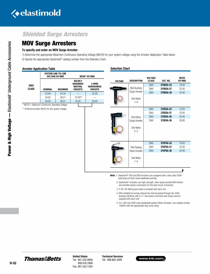
www.tnb.comUnited StatesTel: 901.252.8000 800.816.7809Fax: 901.252.1354
Technical ServicesTel: 888.862.3289
H-52
Shielded Surge Arresters
Pow
er &
Hig
h Vo
ltage
— E
last
imol
d® U
nder
grou
nd C
able
Acc
esso
ries
Selection Chart
PiCture deSCriPtionvoltage
ClaSS Cat. no.mCov
kv rmS
BSA BushingSurge Arrester
See Notes1–4
35kV 375BSa-24 19.5035kV 375BSa-27 22.0035kV 375BSa-30 24.40
ESA ElbowSurge Arrester
See Notes2–3
35kV 375eSa-24 19.5035kV 375eSa-27 22.0035kV 375eSa-30 24.4035kV 375eSa-36 29.00
PSA ParkingStand Arrester
See Notes1–3
35kV 375PSa-24 19.5035kV 375PSa-27 22.0035kV 375PSa-30 24.40
to specify and order an mov Surge arrester:1) Determine the appropriate Maximum Continuous Operating Voltage (MCOV) for your system voltage using the Arrester Application Table below.
2) Specify the appropriate Elastimold® catalog number from the Selection Chart.
Note: 1. Elastimold® PSA and BSA Arresters are equipped with a fully rated 200A switching and fault-close loadbreak bushing.
2. Elastimold® Arresters use high-strength, silver epoxy-bonded MOV blocks and shunted spring connections for the best circuit connection.
3. A 36" #4 AWG ground lead is provided with each unit.
4. BSA installed by turning internal hex bolt (accessed through the 200A bushing interface) with a 5⁄16" hex wrench and bent-wire torque wrench supplied with each unit.
5. For 15kV and 25kV class deadbreak system Elbow Arresters, use catalog number 156ESA with the appropriate duty cycle rating.
MOV Surge Arresters
arrester application table
35kv ClaSS
SyStem line-to-linevoltage kv rmS mCov* kv rmS
nominal maximum
Solidly grounded neutral CirCuitS
3-Wire ungrounded
CirCuitS
23.00 24.34 — 22.0034.50 36.51 22.00** —34.50 36.51 24.40 29.00
* MCOV = Maximum Continuous Operating Voltage.
** Preferred arrester MCOV for this system voltage.
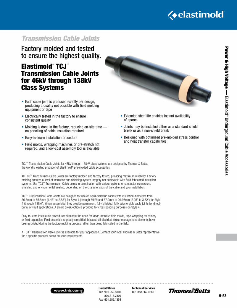
United StatesTel: 901.252.8000 800.816.7809Fax: 901.252.1354
Technical ServicesTel: 888.862.3289www.tnb.com
H-53
Transmission Cable Joints
Power &
High Voltage — Elastim
old® Underground Cable Accessories
Factory molded and tested to ensure the highest quality.
Elastimold® TCJ™ Transmission Cable Joints for 46kV through 138kV Class Systems
• Each cable joint is produced exactly per design, producing a quality not possible with field molding equipment or tape
• Electrically tested in the factory to ensure consistent quality
• Molding is done in the factory, reducing on-site time — no penciling of cable insulation required
• Easy-to-learn installation procedure
• Field molds, wrapping machines or pre-stretch not required, and a low-cost assembly tool is available
TCJ™ Transmission Cable Joints for 46kV through 138kV class systems are designed by Thomas & Betts, the world’s leading producer of Elastimold® pre-molded cable accessories.
All TCJ™ Transmission Cable Joints are factory molded and factory tested, providing maximum reliability. Factory molding ensures a level of insulation and shielding system integrity not achievable with field-fabricated insulation systems. Use TCJ™ Transmission Cable Joints in combination with various options for conductor connectors, shielding and environmental sealing, depending on the characteristics of the cable and your installation.
TCJ™ Transmission Cable Joints are designed for use on solid dielectric cables with insulation diameters from 36.5mm to 65.5mm (1.43" to 2.58") for Style 1 (through 69kV) and 57.2mm to 91.96mm (2.25" to 3.62") for Style 4 (through 138kV). When assembled, they provide permanent, fully shielded, fully submersible cable joints for direct-burial or vault applications. A shield break option is provided for cross bonding purposes on Style 4.
Easy-to-learn installation procedures eliminate the need for labor-intensive field molds, tape-wrapping machinery or field expansion. Field assembly is greatly simplified, because all electrical stress-management elements have been provided during the factory-molding process rather than being fabricated in the field.
A TCJ™ Transmission Cable Joint is available for your application. Contact your local Thomas & Betts representative for a specific proposal based on your requirements.
• Extended shelf life enables instant availability of spares
• Joints may be installed either as a standard shield break or as a non-shield break
• Designed with optimized pre-molded stress control and heat transfer capabilities
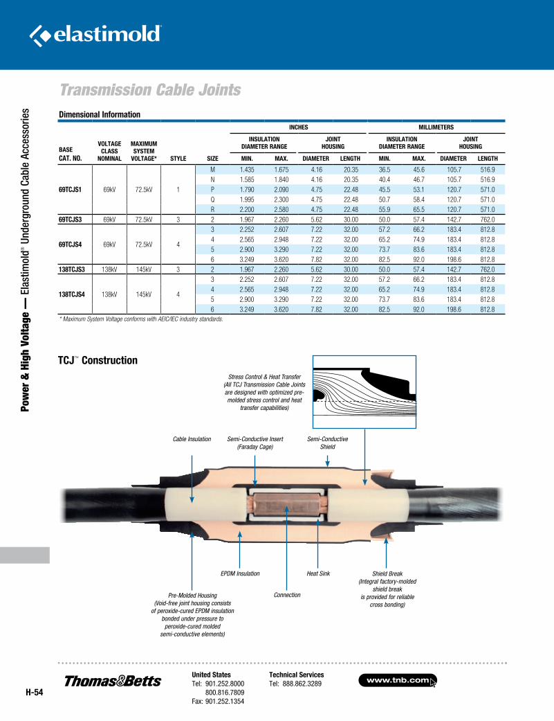
www.tnb.comUnited StatesTel: 901.252.8000 800.816.7809Fax: 901.252.1354
Technical ServicesTel: 888.862.3289
H-54
Transmission Cable Joints
Pow
er &
Hig
h Vo
ltage
— E
last
imol
d® U
nder
grou
nd C
able
Acc
esso
ries Dimensional Information
Base Cat. no.
voltage Class
nomInal
maxImum system
voltage* style sIze
InCHes mIllImeters
InsulatIon DIameter range
joInt HousIng
InsulatIon DIameter range
joInt HousIng
mIn. max. DIameter lengtH mIn. max. DIameter lengtH
69tCjs1 69kV 72.5kV 1
M 1.435 1.675 4.16 20.35 36.5 45.6 105.7 516.9N 1.585 1.840 4.16 20.35 40.4 46.7 105.7 516.9P 1.790 2.090 4.75 22.48 45.5 53.1 120.7 571.0Q 1.995 2.300 4.75 22.48 50.7 58.4 120.7 571.0R 2.200 2.580 4.75 22.48 55.9 65.5 120.7 571.0
69tCjs3 69kV 72.5kV 3 2 1.967 2.260 5.62 30.00 50.0 57.4 142.7 762.0
69tCjs4 69kV 72.5kV 4
3 2.252 2.607 7.22 32.00 57.2 66.2 183.4 812.84 2.565 2.948 7.22 32.00 65.2 74.9 183.4 812.85 2.900 3.290 7.22 32.00 73.7 83.6 183.4 812.86 3.249 3.620 7.82 32.00 82.5 92.0 198.6 812.8
138tCjs3 138kV 145kV 3 2 1.967 2.260 5.62 30.00 50.0 57.4 142.7 762.0
138tCjs4 138kV 145kV 4
3 2.252 2.607 7.22 32.00 57.2 66.2 183.4 812.84 2.565 2.948 7.22 32.00 65.2 74.9 183.4 812.85 2.900 3.290 7.22 32.00 73.7 83.6 183.4 812.86 3.249 3.620 7.82 32.00 82.5 92.0 198.6 812.8
* Maximum System Voltage conforms with AEIC/IEC industry standards.
EPDM Insulation
Semi-Conductive Insert (Faraday Cage)
Semi-Conductive Shield
Cable Insulation
Heat Sink
Connection
Shield Break (Integral factory-molded
shield break is provided for reliable
cross bonding)
Stress Control & Heat Transfer (All TCJ Transmission Cable Joints are designed with optimized pre-molded stress control and heat
transfer capabilities)
Pre-Molded Housing (Void-free joint housing consists
of peroxide-cured EPDM insulation bonded under pressure to
peroxide-cured molded semi-conductive elements)
tCj™ Construction
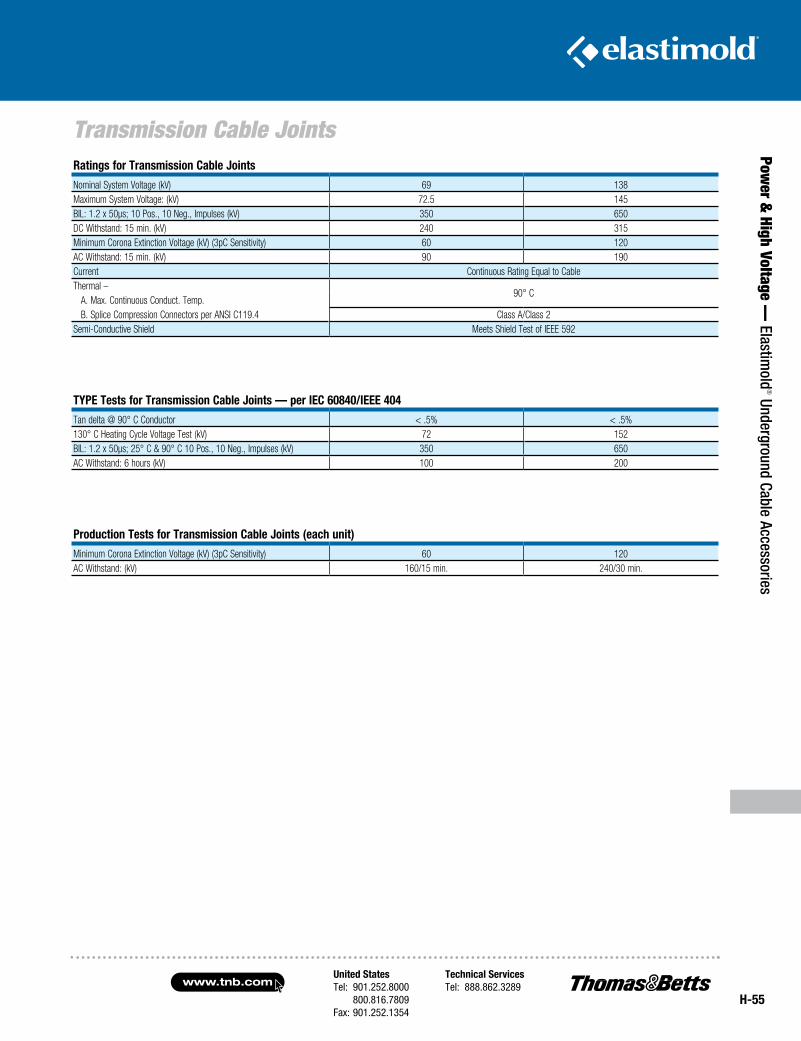
United StatesTel: 901.252.8000 800.816.7809Fax: 901.252.1354
Technical ServicesTel: 888.862.3289www.tnb.com
H-55
Transmission Cable Joints
Power &
High Voltage — Elastim
old® Underground Cable Accessories
ratings for transmission Cable joints
Nominal System Voltage (kV) 69 138Maximum System Voltage: (kV) 72.5 145BIL: 1.2 x 50µs; 10 Pos., 10 Neg., Impulses (kV) 350 650DC Withstand: 15 min. (kV) 240 315Minimum Corona Extinction Voltage (kV) (3pC Sensitivity) 60 120AC Withstand: 15 min. (kV) 90 190Current Continuous Rating Equal to CableThermal –
90° C A. Max. Continuous Conduct. Temp. B. Splice Compression Connectors per ANSI C119.4 Class A/Class 2Semi-Conductive Shield Meets Shield Test of IEEE 592
tyPe tests for transmission Cable joints — per IeC 60840/Ieee 404
Tan delta @ 90° C Conductor < .5% < .5%130° C Heating Cycle Voltage Test (kV) 72 152BIL: 1.2 x 50µs; 25° C & 90° C 10 Pos., 10 Neg., Impulses (kV) 350 650AC Withstand: 6 hours (kV) 100 200
Production tests for transmission Cable joints (each unit)
Minimum Corona Extinction Voltage (kV) (3pC Sensitivity) 60 120AC Withstand: (kV) 160/15 min. 240/30 min.
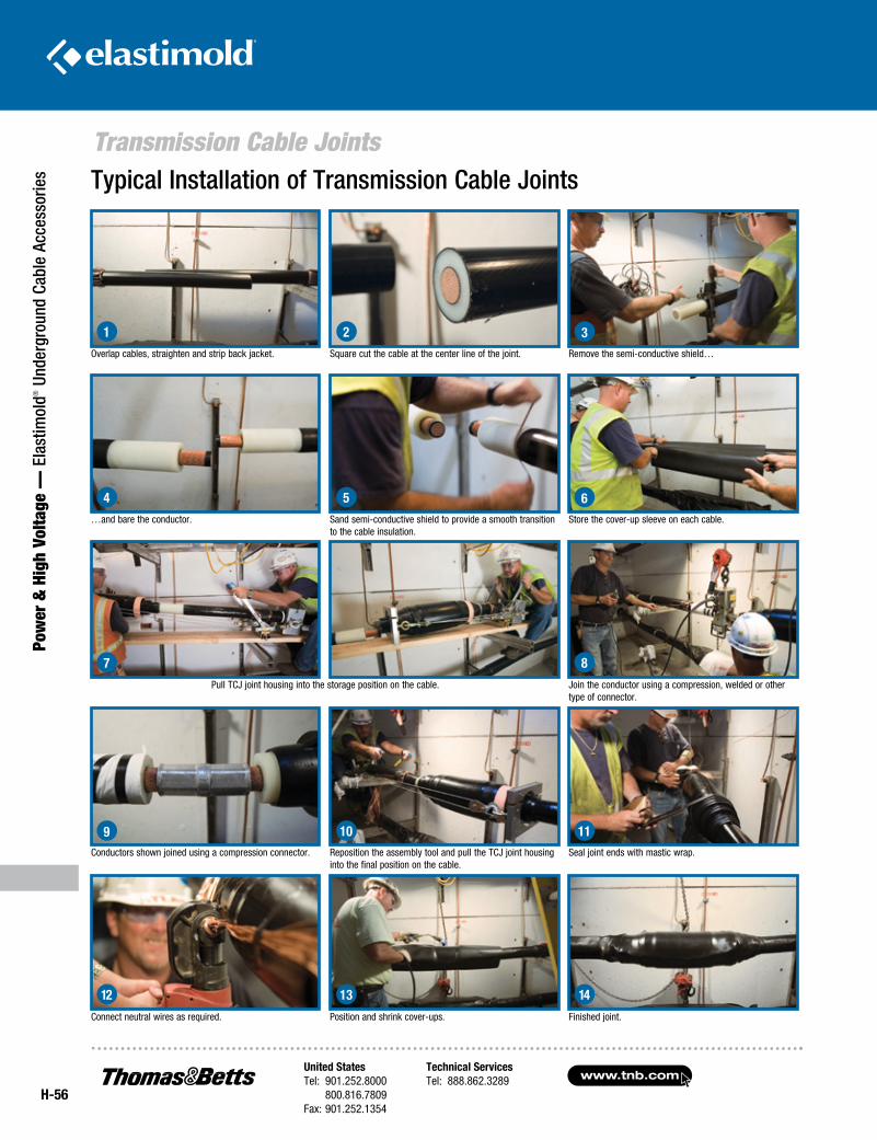
www.tnb.comUnited StatesTel: 901.252.8000 800.816.7809Fax: 901.252.1354
Technical ServicesTel: 888.862.3289
H-56
Pow
er &
Hig
h Vo
ltage
— E
last
imol
d® U
nder
grou
nd C
able
Acc
esso
ries
Transmission Cable JointsTypical Installation of Transmission Cable Joints
Overlap cables, straighten and strip back jacket.
…and bare the conductor.
Pull TCJ joint housing into the storage position on the cable.
Conductors shown joined using a compression connector.
Square cut the cable at the center line of the joint.
Sand semi-conductive shield to provide a smooth transition to the cable insulation.
Reposition the assembly tool and pull the TCJ joint housing into the final position on the cable.
Remove the semi-conductive shield…
Store the cover-up sleeve on each cable.
Join the conductor using a compression, welded or other type of connector.
Seal joint ends with mastic wrap.
Connect neutral wires as required. Position and shrink cover-ups. Finished joint.
1 2 3
4 5 6
7 8
9 10 11
12 13 14
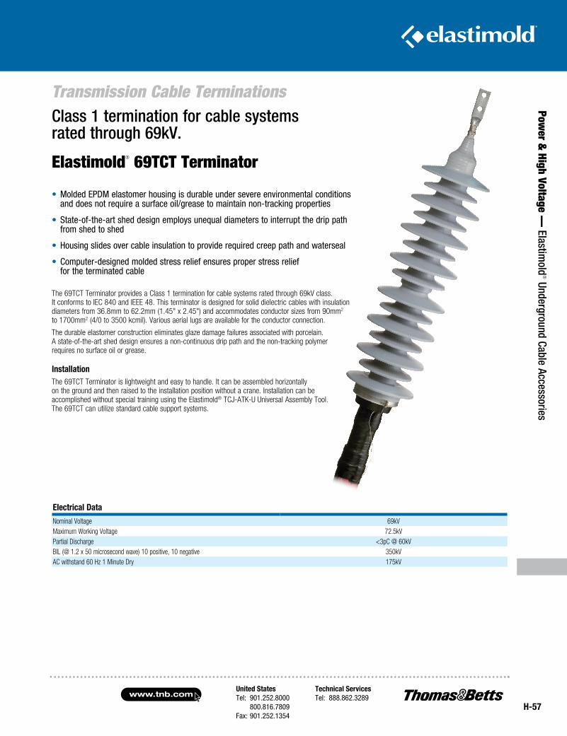
United StatesTel: 901.252.8000 800.816.7809Fax: 901.252.1354
Technical ServicesTel: 888.862.3289www.tnb.com
H-57
Power &
High Voltage — Elastim
old® Underground Cable Accessories
Transmission Cable Terminations
Electrical Data
Nominal Voltage 69kVMaximum Working Voltage 72.5kVPartial Discharge <3pC @ 60kVBIL (@ 1.2 x 50 microsecond wave) 10 positive, 10 negative 350kVAC withstand 60 Hz 1 Minute Dry 175kV
• Molded EPDM elastomer housing is durable under severe environmental conditions and does not require a surface oil/grease to maintain non-tracking properties
• State-of-the-art shed design employs unequal diameters to interrupt the drip path from shed to shed
• Housing slides over cable insulation to provide required creep path and waterseal
• Computer-designed molded stress relief ensures proper stress relief for the terminated cable
Class 1 termination for cable systems rated through 69kV.
Elastimold® 69TCT Terminator
The 69TCT Terminator provides a Class 1 termination for cable systems rated through 69kV class. It conforms to IEC 840 and IEEE 48. This terminator is designed for solid dielectric cables with insulation diameters from 36.8mm to 62.2mm (1.45" x 2.45") and accommodates conductor sizes from 90mm2 to 1700mm2 (4/0 to 3500 kcmil). Various aerial lugs are available for the conductor connection.
The durable elastomer construction eliminates glaze damage failures associated with porcelain. A state-of-the-art shed design ensures a non-continuous drip path and the non-tracking polymer requires no surface oil or grease.
InstallationThe 69TCT Terminator is lightweight and easy to handle. It can be assembled horizontally on the ground and then raised to the installation position without a crane. Installation can be accomplished without special training using the Elastimold® TCJ-ATK-U Universal Assembly Tool. The 69TCT can utilize standard cable support systems.
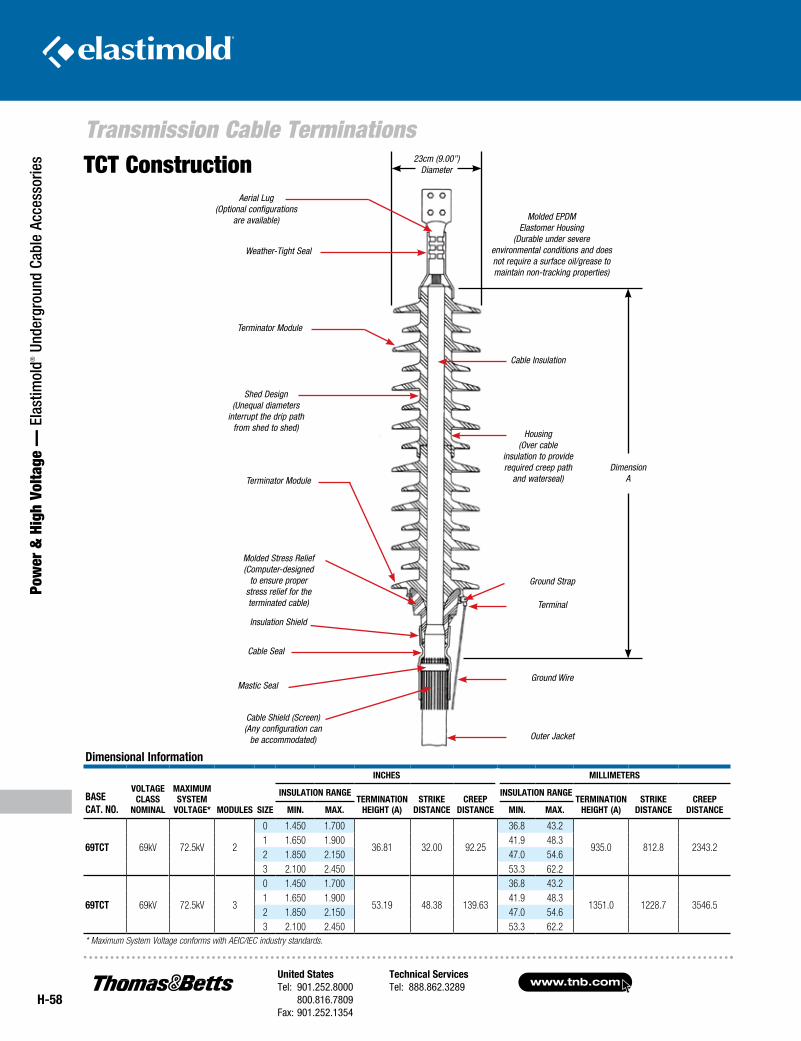
www.tnb.comUnited StatesTel: 901.252.8000 800.816.7809Fax: 901.252.1354
Technical ServicesTel: 888.862.3289
H-58
Transmission Cable Terminations
Pow
er &
Hig
h Vo
ltage
— E
last
imol
d® U
nder
grou
nd C
able
Acc
esso
ries TCT Construction
Dimension A
Aerial Lug(Optional configurations
are available) Molded EPDM Elastomer Housing
(Durable under severe environmental conditions and does not require a surface oil/grease to maintain non-tracking properties)
Weather-Tight Seal
Mastic Seal
Cable Seal
Insulation Shield
Shed Design(Unequal diameters
interrupt the drip path from shed to shed)
Cable Insulation
Housing(Over cable
insulation to provide required creep path
and waterseal)
Terminal
Ground Wire
Outer Jacket
Ground Strap
Molded Stress Relief(Computer-designed
to ensure proper stress relief for the terminated cable)
Cable Shield (Screen)(Any configuration can
be accommodated)
Terminator Module
Terminator Module
Dimensional Information
Basecat. no.
Voltageclass
nomInal
maxImumsystem
Voltage* moDules sIze
IncHes mIllImeters
InsulatIon rangetermInatIon
HeIgHt (a)strIke
DIstancecreep
DIstance
InsulatIon rangetermInatIon
HeIgHt (a)strIke
DIstancecreep
DIstancemIn. max. mIn. max.
69tct 69kV 72.5kV 2
0 1.450 1.700
36.81 32.00 92.25
36.8 43.2
935.0 812.8 2343.21 1.650 1.900 41.9 48.32 1.850 2.150 47.0 54.63 2.100 2.450 53.3 62.2
69tct 69kV 72.5kV 3
0 1.450 1.700
53.19 48.38 139.63
36.8 43.2
1351.0 1228.7 3546.51 1.650 1.900 41.9 48.32 1.850 2.150 47.0 54.63 2.100 2.450 53.3 62.2
* Maximum System Voltage conforms with AEIC/IEC industry standards.
23cm (9.00")Diameter
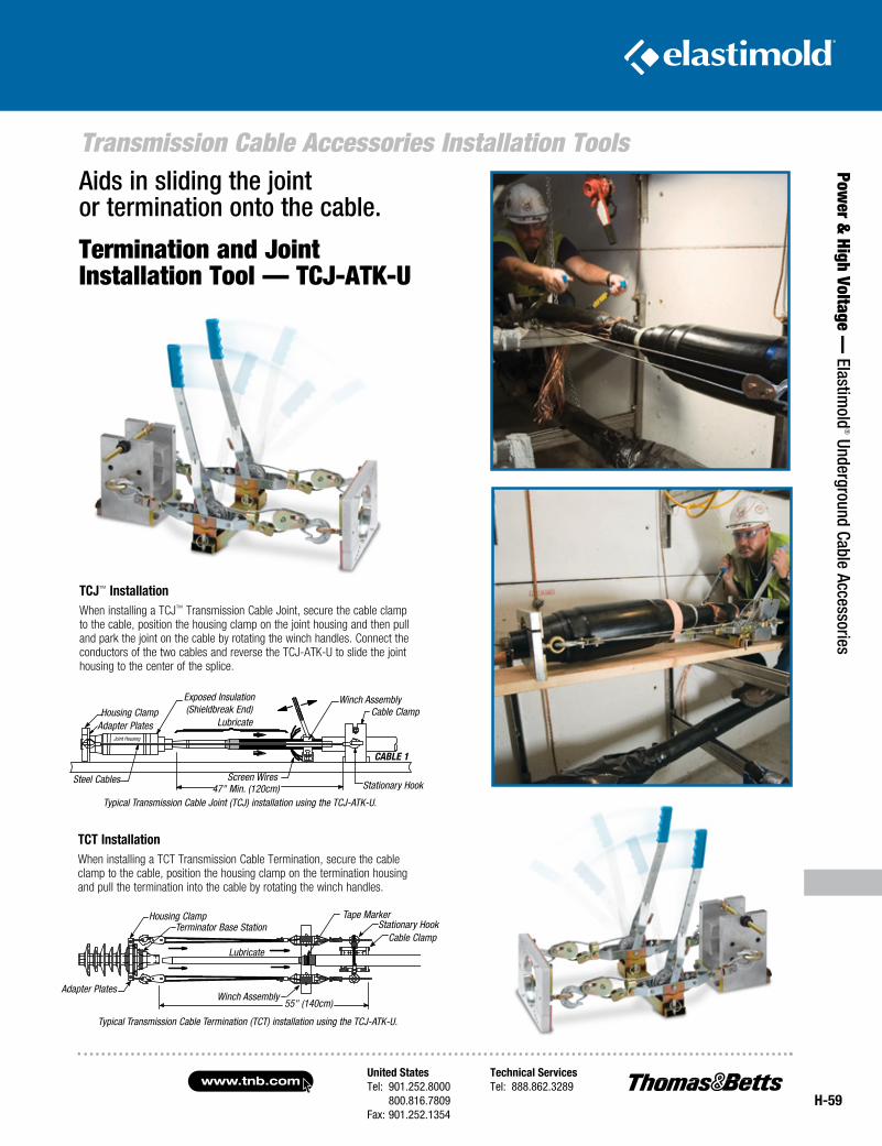
United StatesTel: 901.252.8000 800.816.7809Fax: 901.252.1354
Technical ServicesTel: 888.862.3289www.tnb.com
H-59
Transmission Cable Accessories Installation Tools
Power &
High Voltage — Elastim
old® Underground Cable Accessories
Aids in sliding the joint or termination onto the cable.
Termination and Joint Installation Tool — TCJ-ATK-U
tcJ™ InstallationWhen installing a TCJ™ Transmission Cable Joint, secure the cable clamp to the cable, position the housing clamp on the joint housing and then pull and park the joint on the cable by rotating the winch handles. Connect the conductors of the two cables and reverse the TCJ-ATK-U to slide the joint housing to the center of the splice.
Typical Transmission Cable Joint (TCJ) installation using the TCJ-ATK-U.
Steel Cables Screen WiresStationary Hook
CABLE 1
Cable ClampWinch AssemblyExposed Insulation
(Shieldbreak End)Lubricate
Housing ClampAdapter Plates
Joint Housing
47" Min. (120cm)
tct InstallationWhen installing a TCT Transmission Cable Termination, secure the cable clamp to the cable, position the housing clamp on the termination housing and pull the termination into the cable by rotating the winch handles.
Typical Transmission Cable Termination (TCT) installation using the TCJ-ATK-U.
Adapter PlatesWinch Assembly
55" (140cm)
Cable ClampStationary Hook
Tape MarkerTerminator Base Station
Housing Clamp
Lubricate
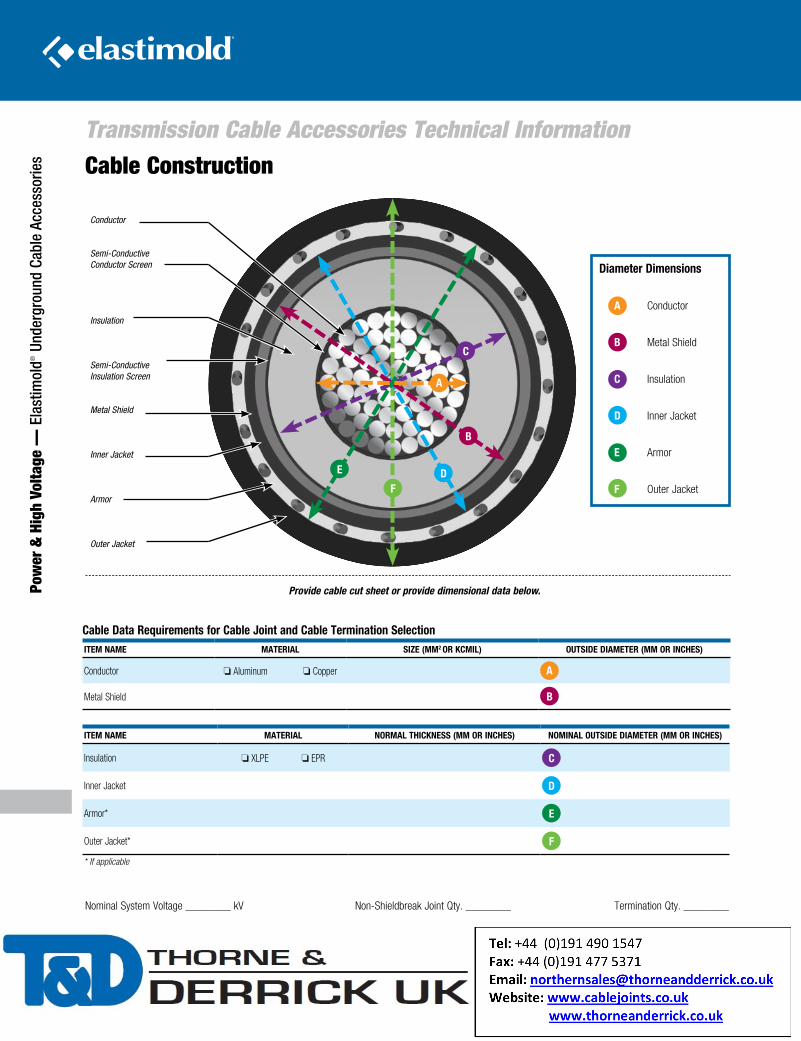
www.tnb.comUnited StatesTel: 901.252.8000 800.816.7809Fax: 901.252.1354
Technical ServicesTel: 888.862.3289
H-60
Pow
er &
Hig
h Vo
ltage
— E
last
imol
d® U
nder
grou
nd C
able
Acc
esso
ries
Transmission Cable Accessories Technical InformationCable Construction
Conductor
Semi-Conductive Conductor Screen
Insulation
Semi-Conductive Insulation Screen
Metal Shield
Inner Jacket
Armor
Outer Jacket
A
B
C
DE
F
Cable Data Requirements for Cable Joint and Cable Termination SelectionITEm NAmE mATERIAl SIzE (mm2 oR kCmIl) ouTSIDE DIAmETER (mm oR INCHES)
Conductor o Aluminum o Copper A
Metal Shield B
Provide cable cut sheet or provide dimensional data below.
ITEm NAmE mATERIAl NoRmAl THICkNESS (mm oR INCHES) NomINAl ouTSIDE DIAmETER (mm oR INCHES)
Insulation o XLPE o EPR C
Inner Jacket D
Armor* E
Outer Jacket* F
* If applicable
Nominal System Voltage ________ kV Non-Shieldbreak Joint Qty. ________ Termination Qty. ________
Diameter Dimensions
A Conductor
B Metal Shield
C Insulation
D Inner Jacket
E Armor
F Outer Jacket
Pamela Kinnell
Address Stamp