PCS 2 - Frank's Hospital Workshopfrankshospitalworkshop.com/equipment/documents/... · HAEMONETICS...
134
HAEMONETICS ® PCS ® 2 Service and Maintenance Manual
Transcript of PCS 2 - Frank's Hospital Workshopfrankshospitalworkshop.com/equipment/documents/... · HAEMONETICS...

HAEMONETICS®
PCS®2
Service and Maintenance Manual

HAEMONETICS®
PCS®2
Part Number 38855-00Rev. D, June 2003
HAEMONETICS CORPORATION400 Wood Road, Braintree, MA 02184
Service and Maintenance Manual

© 1994 Haemonetics CorporationAll Rights ReservedPrinted in U.S.A.First Printing, April 1994
PROPRIETARY MATERIALInformation and descriptions contained herein are the property ofHaemonetics Corporation. Except where indicated, such information anddescriptions may not be copied or reproduced by any means, ordisseminated or distributed without the express prior written permission ofHaemonetics Corporation.
TRADEMARKSHAEMONETICS® and PCS®2 are registered trademarks of HaemoneticsCorporation.
ii PCS2 Service Manual
Chapter 1, Introduction
General..........................................................................................................................................1-1Additional Support .......................................................................................................................1-2
Chapter 2, Machine Part Replacement Reference
Cautions........................................................................................................................................2-1Static Discharge............................................................................................................................2-1Notes.............................................................................................................................................2-1Rear Panel.....................................................................................................................................2-2
Fan Assembly .........................................................................................................................2-2Cover Stops.............................................................................................................................2-2Cuff Connector .......................................................................................................................2-2
Front Panel....................................................................................................................................2-2Donor Line Air Detectors 1 and 2 ..........................................................................................2-3Compressor.............................................................................................................................2-3Front Panel Distribution Board...............................................................................................2-4
Card Cage .....................................................................................................................................2-4Centrifuge Distribution Card ..................................................................................................2-4Processor Card........................................................................................................................2-5Main Program Chip Assembly ...............................................................................................2-5Safety Card .............................................................................................................................2-5Driver Card .............................................................................................................................2-6Backplane Card (Mother Board) ............................................................................................2-6
Top Deck Assembly......................................................................................................................2-6AC Air Detector................................................................................................................2-6Blood Line Air Detector ...................................................................................................2-7
Line Sensor .............................................................................................................................2-7Top Deck Distribution Board..................................................................................................2-7
Plasma Weigher Assembly ...........................................................................................................2-8Weigher Arm Assembly .........................................................................................................2-8
Table of Contents

Chapter 2, Machine Part Replacement Reference, cont.
Load Cell ................................................................................................................................2-8Pinch Valves ...........................................................................................................................2-9AC/Blood Pump Assembly...................................................................................................2-10
Rotor ...............................................................................................................................2-10Motor ..............................................................................................................................2-11
SPM/DPM Sensor Assembly................................................................................................2-11Centrifuge Assembly ..................................................................................................................2-12
Cover Halves ..................................................................................................................2-12Bushing Adjustment Kit .................................................................................................2-13Cover Switch Assembly .................................................................................................2-15Cover Latch ....................................................................................................................2-15Fluid Sensor Assembly...................................................................................................2-16Bowl Optics Assembly ...................................................................................................2-16
Top Cover Assembly ..................................................................................................................2-17Membrane Panel Assembly ..................................................................................................2-17
Control Panel Distribution Cable....................................................................................2-18Display Distribution Board...................................................................................................2-20Vacuum Display....................................................................................................................2-20Membrane Panel ...................................................................................................................2-20
Power Entry Module...................................................................................................................2-21Fuse.......................................................................................................................................2-21
Power Supply Assembly.............................................................................................................2-21Replace Todd Power Supply with Todd Power Supply ........................................................2-21Replace Todd Power Supply with Condor Power Supply ....................................................2-22Replace Condor Power Supply with Condor Power Supply ................................................2-23Centrifuge Controller Card...................................................................................................2-24
AC and Saline Pole Holder Assembly........................................................................................2-24Drain Tube Assembly .................................................................................................................2-24Photoelectric Assembly ..............................................................................................................2-24Line Conditioner.........................................................................................................................2-25Table 2-1, PCS2 Component Calibration and Diagnostic Matrix ..............................................2-26
Chapter 3, Basic Care and Preventive Maintenance
Initial Inspection...........................................................................................................................3-1Visual Inspection ....................................................................................................................3-1Ensure Initial Operational Integrity ........................................................................................3-2Record the Program Revision Level.......................................................................................3-2
System Cleaning...........................................................................................................................3-2Equipment Integrity Inspection ....................................................................................................3-2
Electrical Connections Inspection ..........................................................................................3-2
toc-ii PCS2 Service Manual
PCS2 Service Manual toc-iii
Chapter 3, Preventive Maintenance, cont.
Pneumatic Connections Inspection.........................................................................................3-2Hardware Inspection...............................................................................................................3-2
Consumables Replacement...........................................................................................................3-3Filter Inspection......................................................................................................................3-3
Calibration Testing .......................................................................................................................3-3Power Supply Voltages Test ...................................................................................................3-3Valves Test ..............................................................................................................................3-4Valve Occlusion Test ..............................................................................................................3-4Weigher Test ...........................................................................................................................3-5DPM Sensor Test ....................................................................................................................3-5Cuff Test .................................................................................................................................3-6Display Test ............................................................................................................................3-6Keyboard Test .........................................................................................................................3-6
Centrifuge Testing ........................................................................................................................3-7Fluid Sensor Test ....................................................................................................................3-7Centrifuge Cover and Lock Functional Test...........................................................................3-7Centrifuge Speed and Bowl Vibration Test ............................................................................3-7Donor Lights Test ...................................................................................................................3-7Line Sensor Test .....................................................................................................................3-8Bowl Optics Signal Test .........................................................................................................3-8Air Detector Test ..................................................................................................................3-10PCS2 Functional Test ...........................................................................................................3-10
Safety Testing .............................................................................................................................3-12Leakage Current ...................................................................................................................3-12Ground Continuity................................................................................................................3-12
Chapter 4, Calibration
Calibration Procedures .................................................................................................................4-1Power Supply Voltages ...........................................................................................................4-1
Todd Power Supply...........................................................................................................4-1Condor Power Supply.......................................................................................................4-3
Bowl Optics Signal .................................................................................................................4-3Line Sensor Signal..................................................................................................................4-6A/D .........................................................................................................................................4-6
Cuff ...................................................................................................................................4-6Weigher.............................................................................................................................4-7
P/N 36924-00 Weigher Arm .......................................................................................4-7P/N 52025-00 Weigher Arm .......................................................................................4-8Weigher Calibration When Using Collection Bottles.................................................4-8Weigher Calibration When Using Collection Bags ....................................................4-9
Chapter 4, Calibration, cont.
Weigher Calibration When Using Collection Bottles and Bags .................................4-9DPM ..............................................................................................................................4-9
Centrifuge .............................................................................................................................4-10Safety System .......................................................................................................................4-11
Chapter 5, Installation and Configuration
Initial Inspection...........................................................................................................................5-1Overall Cosmetic Check.........................................................................................................5-1Internal Workmanship ............................................................................................................5-1
Configuration of Protocol Parameters ..........................................................................................5-1Language Configuration .........................................................................................................5-1Protocol Selection...................................................................................................................5-2Machine Settings ....................................................................................................................5-3Serial Number Configuration .................................................................................................5-4Collection Weight Configuration............................................................................................5-4Bowl Configuration ................................................................................................................5-5
Testing ..........................................................................................................................................5-6Valves Test ..............................................................................................................................5-6Weigher Test ...........................................................................................................................5-6DPM Sensor Test ....................................................................................................................5-7Cuff Test .................................................................................................................................5-7Display Test ............................................................................................................................5-7Keyboard Test .........................................................................................................................5-8Centrifuge Testing ..................................................................................................................5-8
Fluid Sensor Test ..............................................................................................................5-8Centrifuge Cover & Lock Function Test ..........................................................................5-8Centrifuge Speed and Bowl Vibration Test ......................................................................5-8
Donor Lights Test ...................................................................................................................5-9Line Sensor Test .....................................................................................................................5-9Bowl Optics Signal Test .........................................................................................................5-9Air Detector Test ..................................................................................................................5-11PCS2 Functional Test ...........................................................................................................5-11Leakage Current ...................................................................................................................5-13Ground Continuity................................................................................................................5-13
Machine Transfers ......................................................................................................................5-14Source Plasma Customers Only ...........................................................................................5-14PCS2 Machine Transfer Verfication Form ...........................................................................5-15
toc-iv PCS2 Service Manual
PCS2 Service Manual toc-v
Chapter 6, TroubleshootingMessages.......................................................................................................................................6-1
Status Messages......................................................................................................................6-2Error Messages .......................................................................................................................6-2
CPU Error Messages ........................................................................................................6-3Notes ..............................................................................................................................6-4CPU Error Message List...................................................................................................6-5
Safety System Error Messages .............................................................................................6-32Command Register .........................................................................................................6-33
Table 6-1, Error Codes of the Command Register....................................................6-33Fault Register..................................................................................................................6-33
Table 6-2, Error Codes of the Fault Register ............................................................6-34Critical Register..............................................................................................................6-35
Table 6-3, Error Codes of the Critical Register ........................................................6-35
Chapter 7, Repair Parts List
PCS2 Exploded View ...................................................................................................................7-2PCS2 Exploded View with Callouts .............................................................................................7-3PCS2 Centrifuge Exploded Views with Callouts .........................................................................7-4PCS2 Card Cage and Air Filters Exploded Views with Callouts .................................................7-5PCS2 Power Supply Assembly Exploded Views with Callouts ...................................................7-6PCS2 Pump Assembly Exploded View with Callouts..................................................................7-7Parts List by Assembly .................................................................................................................7-8Used PCS2 Parts Return Procedure............................................................................................7-12
Chapter 8, Cleaning and Maintenance
Overview.......................................................................................................................................8-1Cleaning........................................................................................................................................8-1
Routine Cleaning Schedule ....................................................................................................8-1Cleaning Supplies Needed......................................................................................................8-2Cleaning the PCS2..................................................................................................................8-2
Membrane Panel and Outer Cabinet.................................................................................8-2Donor Pressure Monitor (DPM).......................................................................................8-3Air Detectors.....................................................................................................................8-3Line Sensor .......................................................................................................................8-3Centrifuge Well.................................................................................................................8-4Fluid Sensor......................................................................................................................8-7Bowl Optics Lens .............................................................................................................8-7Blood and Anticoagulant Pumps ......................................................................................8-8
Chapter 8, Cleaning and Maintenance, cont.
Air Filters..........................................................................................................................8-9Internal Chassis.................................................................................................................8-9
Leakage Current Check ..............................................................................................................8-10Return Goods Authorization (RGA)...........................................................................................8-11
RGA Procedure.....................................................................................................................8-11Haemonetics Quality Program....................................................................................................8-12
Chapter 9, Technical Bulletins
toc-vi PCS2 Service Manual

This Service Manual is designed to provide detailed information for theinstallation and maintenance of the PCS2, which is a plasma collectionsystem.
The manual contains nine chapters, including:
Chapter 1, Introduction
Describes the PCS2 Service Manual.
Chapter 2, Machine Part Replacement ReferenceDescribes detailed steps in disassembling the PCS2 and its subsystems.
Chapter 3, Basic Care and Preventive MaintenanceDescribes detailed preventive maintenance procedures.
Chapter 4, Calibration Describes detailed calibration procedures.
Chapter 5, Installation and ConfigurationDescribes detailed installation procedures and configuration of protocolparameters procedures.
Chapter 6, TroubleshootingDescribes each of the CPU and safety system generated error messages,and describes detailed troubleshooting steps to resolve the problems.
Chapter 7, Repair Parts ListProvides exploded views of the PCS2 and its subsystems with partnumber and description call-outs. Includes parts list in assembly outlineformat for each available repair part or assembly.
Chapter 1
Introduction
General
Christine Owen
Chapter 8, Cleaning and MaintenanceDescribes routine maintenance procedures.
Chapter 9, Technical Bulletins.Provides area to store Technical Bulletins.
Many factors affect the performance of component collection devicesincluding the functional integrity of the instrument, the consistency of thedisposable set, and the quality of the blood from the donor.
When the PCS2 is properly calibrated and maintained, the instrument isvery reliable and predictable and is designed to withstand substantialabuse. There may be times, however, that a component may failprematurely, or damage may occur during transport or as the result offluid contamination.
In designing this manual, Haemonetics has attempted to address allpossible service scenarios. There may be situations which were notpredicted, and in such cases Haemonetics Product Support can be reliedupon to provide outstanding service support. Product support can beobtained through the Haemonetics Hot Line at 800-356-3506.
1-2 PCS2 Service Manual
AdditionalSupport
Chapter 2Machine Part Replacement Reference
Extreme caution should be exercised when working inside the PCS2cabinet to avoid electrical shock. Particularly avoid contact with ACpower connections and any electrolytic capacitors on printed circuitboards. Whenever possible, AC power should be disconnected from thePCS2 before opening the cabinet.
The PCS2 uses static sensitive electronics. Serious damage may occur tothe sensitive electronics if static discharge is not controlled. Internalcomponents should only be handled after proper precautions have beentaken to prevent static discharge.
To reassemble the PCS2, reverse the disassembly steps. In some cases,Reassembly Notes have been added to direct your attention to anyimportant steps.
For brevity, a procedure often will reference another procedure. Forinstance, when removing the top deck, the instructions will ask you toremove the centrifuge. Locate the centrifuge removal procedure forinstructions on that particular step.
In most cases there is more than one way to remove a particular assembly.These instructions provide the most logical approach to disassembling thePCS2. With experience, you may develop a less methodical approach. Youare encouraged to use whatever method best suits your particular situation.
When replacing certain machine components, it may be necessary tocalibrate that component as well as other peripheral components.Calibration steps are listed in each component’s replacement procedurewhen needed. In addition, Table 2-1 at the end of this chapter provides aComponent Calibration and Diagnostic Matrix indicating any necessarycalibrations and diagnostic checks required for the specific componentreplacement.
Cautions
StaticDischarge
Notes
2-2 PCS2 Service Manual
1. Remove (3) Phillips head screws from the bottom edge of the rearpanel.
2. Pull bottom edge 6" away from the cabinet, then pull the rear paneldown and away from the upper lip of the cabinet.
3. Unplug the fans at P407 on the centrifuge distribution board.4. Disconnect the cuff pneumatic line at the quick disconnect,
approximately 12 inches from the rear panel.5. Remove the ground wire from the ground lug on the rear panel.
Fan Assembly1. Remove the rear panel.2. Remove (2) nuts for each fan to be removed.
Note: All four fans should be replaced at the same time, even if only oneis failing.
Cover Stops1. Remove the rear panel.2. Remove (2) Phillips head screws for each cover stop to be removed.
Cuff Connector1. Remove the rear panel.2. Remove connector nut.3. Push connector out of panel from rear.
1. Tilt the cabinet back slightly, and remove the (3) Phillips head screwsfrom the bottom edge of the front panel.
2. Pull the front panel away from the cabinet, then pull the panel downand away from the upper lip of the cabinet.
3. Disconnect the cuff pneumatic line at the quick disconnect.4. Disconnect the ribbon cable P503/703 at P703 on the mother
backplane card.5. Remove the ground wire from the ground lug on the front panel.
Rear Panel
Front Panel
Chapter 2, Machine Part Replacement Reference 2-3
Donor Line Air Detectors 1 and 21. Remove the front panel. (See page 2-2.)2. Disconnect air detector from P701 for DLAD1 and/or P702 for
DLAD2 on the front panel distribution board.3. Remove (2) Phillips head screws from each air detector. Be aware of
nylon spacers between air detector mounting holes and front panel.4. Firmly press the air detector head (from the front) through the panel.
This is normally a very tight fit, and may have been lubricated withsilicone vacuum grease when assembled.
Donor Line 1 and 2 Reassembly Notes1. Air detector connectors are keyed to ensure proper location, but the
air detectors themselves could accidentally be installed in the wronglocation. The Donor Line Air Detector #1 at P701 is located in theupper panel location, and the Donor Line Air Detector #2 at P702 islocated in the lower panel location.
2. When installing the air detector, be sure the grommet is in place in thepanel, and lubricate the grommet inner diameter with silicone vacuumgrease to ease the installation of the air detector head.
Note: LED to be located toward the inside of the front panel.
3. When reassembling, assure white nylon spacers are placed betweenair detectors and front panel at the mounting holes.
Compressor1. Remove the front panel. (See page 2-2.)2. Disconnect the compressor at P704 on the front panel distribution
board.3. Remove O-ring around compressor clip, if present.4. Unclasp the compressor from the front panel mounting clip.5. Disconnect the compressor from the pneumatic harness at any
convenient junction.6. Recalibrate compressor. Refer to Chapter 4, Calibration.
Compressor Reassembly NotesThe compressor has a pressure port (P) and a vacuum port (V) that maynot be labeled. The vacuum port (V) has tubing with a filter attached toit for drawing in air. The pressure port (P) has tubing with a filterattached, which is then connected to the pressure transducer and cuffpneumatic harness. If the tubing attached to the pressure and vacuumports are crossed, the compressor will run but there will be no pressureoutput (cuff will not inflate).
2-4 PCS2 Service Manual
Note: The filters should be replaced when a new compressor is installed.
Front Panel Distribution Board1. Remove the front panel. (See page 2-2.)2. Disconnect P701, 702, 703, and 704 from the front panel distribution
board.3. Disconnect the ground wire from TS1.4. Disconnect the compressor pneumatic line at the cuff pressure sensor.
(P2 Port)5. Remove (4) Phillips head screws at the front panel distribution board
corners.6. Recalibrate the compressor. Refer to Chapter 4, Calibration.
1. Remove the front and rear panels. (See page 2-2.)2. From the front cavity, disconnect P501, P502, P503, P504, P506,
P507, and TS1 ground from the backplane card. Label cables as theyare removed.
3. Follow the directions for each of the following card cage boards. Thecage is ultimately removed along with the backplane card.
4. Remove (4) Phillips head screws securing the card cage frame to thecabinet bases (2 in front, 2 in back).
5. Move the frame toward the rear of the cabinet, and slide out the backcavity of the cabinet.
Card Cage Reassembly NotesThe (3) main cards use similar backplane connectors, but the red keysprevent installing the card in the wrong location.
Centrifuge Distribution Card1. Remove the front and rear panels. (See page 2-2.)2. Disconnect P408 and P409 from the centrifuge distribution card (1/2
size board located at the far right of the card cage), then unclasp theblack card levers and partially slide the centrifuge distribution cardout of the card cage.
3. From the rear cavity, disconnect P404, P405, P406, P407, and groundwire at TS1 from the centrifuge distribution card, then completelyremove the centrifuge distribution card from the card cage.
Card Cage
Chapter 2, Machine Part Replacement Reference 2-5
Processor Card1. Remove the rear panel. (See page 2-2.)2. Unclasp the card levers and unplug the processor card from the
backplane card (located at far left of the card cage).3. Slide the card out of the card cage.4. If replacing the processor card, refer to Chapter 4 for calibration of
the bowl optics signal, line sensor signal, A/D, centrifuge, and safetysystem, and Chapter 5 for configuration.
Note: Processor card MUST have Main Program IC (P/N 37008-01) chipin position U26 prior to reassembly. Also, verify that the correctprogram version for your facility is installed. If program version isnot correct contact the Haemonetics Hot Line.
Main Program Chip Assembly1. Remove the processor card. (See above.)2. Using an antistatic IC removal tool for a 32 pin IC, gently pull the
main program IC from chip location U26. A future program upgrademay also utilize U23. If the IC removal tool is not available, use flatblade screwdriver to gently pry between IC chip and IC carrier fromend to end until IC chip is out.
Note: Do NOT bend IC chip legs.
Main Program Chip Reassembly NotesThe Main Program IC chip must be installed properly or the chip will bedestroyed. At one end of the chip there is a small notch (half circle). Thisnotch must align with the white notch silk-screened on the Processor card(notch points toward the backplane connectors).
Safety Card1. Remove the rear panel. (See page 2-2.)2. Unclasp the card levers and unplug the safety card from the backplane
card (located as second card from the left in the card cage).3. Slide the card out of the card cage.4. If replacing the safety card, refer to Chapter 4, Calibration, for
calibration of the safety system.

2-6 PCS2 Service Manual
Driver Card1. Remove the rear panel. (See page 2-2.)2. Unclasp the card levers and unplug the driver card from the backplane
card (located as third card from the left in the card cage).3. Slide the card out of the card cage.4. If replacing the driver card, refer to Chapter 4, Calibration, for
calibration of the safety system.
Backplane Card (Mother Board)1. See all steps to removing the card cage. (See page 2-4.)2. Remove (7) large Phillips head screws securing the backplane card to
the card cage frame.
1. Remove the front and rear panels. (See page 2-2.)2. Remove the centrifuge assembly. (See page 2-12.)3. Disconnect P504 from the backplane card and thread ribbon cable
through the rear panel.4. Disconnect P501, P502, and P506 from the backplane card.5. Disconnect the ground wire at the top deck ground bus that connects
to the side panel ground bus.6. Using a 3/8" wrench (or equivalent), remove the (4) #10-32 nuts that
secure the top deck to the cabinet.7. Firmly grasp the top deck and pull away from the cabinet.
AC Air Detector1. Remove the front and rear panels. (See page 2-2.)2. Disconnect P605 from the top deck distribution board.3. Remove the right handle by removing the (2) Phillips head screws
securing the inner and outer panels.
Note: It may be easier to access the screws if the AC pump is removed.(See page 2-10.)
4. Remove the (2) Phillips head screws securing the air detector to thetop deck.
5. Firmly press the air detector head (from the top) through the top deck.This is a very tight fit.
Note: See reassembly notes below.
Top DeckAssembly

Chapter 2, Machine Part Replacement Reference 2-7
Blood Line Air Detector1. Remove the front and rear panels. (See page 2-2.)2. Remove blood pump assembly for easier access. (See page 2-10.)3. Disconnect P606 from the top deck distribution board.4. Remove the (2) Phillips head screws securing the air detector to the
top deck.5. Firmly press the air detector head (from the top) through the top deck.
This is a very tight fit.
Note: See the following reassembly notes.
AC and Blood Line Air Detector Reassembly Notes1. Apply a light film of silicone vacuum grease to the air detector
grommet before attempting to install the air detector.2. If both top deck air detectors are removed, be sure to return the
correct air detectors to the correct locations. The plugs are keyed, souse the descriptions on the top deck distribution board foridentification. P605 is for the AC and P606 is for the Blood Line AirDetector.
3. LED is located toward the front of unit.
Line Sensor1. Remove the rear panel. (See page 2-2.)2. Disconnect P607 from the top deck distribution board.3. Remove the (2) Phillips head screws securing the line sensor to the
top deck.
Note: It may be necessary to use a ratchet or stubby screwdriver to accessthese screws. If you still have trouble, you may have to slide thecard cage back.
Line Sensor Reassembly Notes1. Be sure the line sensor gasket is in place between the sensor and the
top deck before securing.2. Calibrate the line sensor. Refer to the procedure in Chapter 4, Calibration.
Top Deck Distribution Board1. Remove the front and rear panels. (See page 2-2.)2. Remove the centrifuge. (See page 2-12.)3. Remove the pumps. (See page 2-10.)4. Remove or slide back the card cage (See page 2-4.)

2-8 PCS2 Service Manual
5. Disconnect all electrical connections on the top deck distributionboard including the ground.
6. Remove the (6) Phillips head screws securing the top deck distributionboard to the top deck.
Note: The top deck assembly may be removed as an alternative method.(See page 2-6.)
Weigher Arm Assembly
Note: Extreme care must be used when doing this.
1. Remove the Phillips screw securing the weigher arm to the load cellstandoff.
2. Remove the arm from the load cell upper standoff.
Weigher Arm Reassembly NotesThe weigher arm is secured to the load cell by a screw mounted to thehexagonal shaped upper standoff assembly. The upper standoff ispermanently attached to the stainless steel stud, connecting to the lowersquare standoff mounted inside the spring clip. This mountingconfiguration allows the lower standoff to be rotated in one of fourpositions. When securing the weigher arm to the upper standoff, ensurethe weigher arm is adjusted to be perpendicular to the machine cabinetwhen the lower standoff is in one of its four positions. This may prove tobe difficult without securing the load cell upper standoff with a 1/4 inchopen wrench under the top deck while tightening the weigher arm screw.If tightened properly the arm and lower standoff will rotate as an integralpiece. Purple Loctite must be used on the screw that attaches the weigherarm to the upper standoff.
Load Cell
Note: The load cell is a sensitive device and should be handled with care.
1. Remove the front and rear panels. (See page 2-2.)2. Disconnect P506 from the backplane card and thread the cable around
the side of the card cage.3. Remove the weigher arm assembly (See above.)4. Remove the centrifuge assembly (See page 2-12.) or slide the card
cage back (See page 2-4.) approximately six inches to allow clearanceto the weigher load cell.
5. Using a 7/32" wrench (or equivalent), remove the (2) M3 nuts,washers, and compression springs securing the load cell to the topdeck.
PlasmaWeigher
Assembly

Chapter 2, Machine Part Replacement Reference 2-9
Load Cell Reassembly Notes1. When routing the P506 wire, run the wire between the front panel and
the pinch valves. Do NOT run the wire between the backplane cardand the pinch valves. This could cause the machine to short out.
2. When attaching the load cell to the top deck, the spring fits over thesecuring shaft first, then the washer and then the nut. When tighteningthe nuts, tighten until nut is even with the bottom of stud. Turn nut sixmore complete revolutions.
3. Recalibrate the weigher assembly following the procedure in Chapter4, Calibration.
Load Cell Lower Standoff ReplacementNote: The load cell lower standoff replacement should only be performed
by Haemonetics personnel.
1. Remove the load cell assembly. (See page 2-8.)2. Using a 1/4" wrench, secure the load cell’s upper standoff and using a
5/64" hex wrench, remove the setscrew located inside the load cell’slower standoff. (Save this setscrew as it will be reinstalled in thereplacement standoff.)
3. Securing the upper standoff, unscrew and remove the lower standofffrom the load cell assembly.
Note: Do not remove the upper standoff from the load cell assembly.
Load Cell Lower Standoff Reassembly Notes1. When installing the replacement standoff, ensure that the standoff is
between the spring clip.2. When securing the standoff to the load cell assembly, tighten the
upper standoff to the lower standoff until the entire assembly is handtight, and then secure the standoff assembly by tightening the setscrewin the lower standoff using the 5/64" hex wrench.
3. Ensure that the upper standoff rotates smoothly and easily with aslight click before reinstalling the load cell assembly.
4. Recalibrate the weigher assembly, following the procedure in Chapter4, Calibration, after the load cell and weigher arm have beenreinstalled.
Pinch Valves1. Remove the front panel. (See page 2-2.)2. Using 11/16" wrench (or equivalent), remove (1) #8-32 nut securing
the ground wire of the valve to be removed to the ground lug.

2-10 PCS2 Service Manual
3. Disconnect P608 for the Saline Valve, P609 for the Plasma Valve,and/or P611 for the Donor Valve.
4. Using 11/16" wrench (or equivalent), remove (2) #8-32 nuts securingthe valve to the cabinet top deck.
5. Pull valve down through the top deck.
Note: The pinch valves’ harnesses may be tie-wrapped together. The tie-wraps will need to be cut if the valve is to be removed.
Pinch Valve Reassembly Notes1. Lightly lubricate the inside surface of the pinch valve gasket with
silicone vacuum grease.2. Install the gasket into the cabinet with the ridged lip facing up.3. Slide the pinch valve into the gasket and mount into place.4. Wipe excess grease from the pinch valve.5. The three pinch valves are identical. Be sure to install the electrical
connector in the proper location on the top deck distribution board.P608 is the Saline Valve, P609 is the Plasma Valve, and P611 is theDonor Valve.
AC/Blood Pump Assembly1. Remove the rear panel. (See page 2-2.)2. Disconnect P614 and P615 for the AC Pump, or P616 and P617 for
the Blood Pump from the top deck distribution board.3. Remove the (4) Phillips screws securing the pump assembly to the top
deck.4. Partially pull the pump assembly out of the top deck, and remove the
(1) Phillips head screw securing the ground wire to the pump motor.
AC/Blood Pump Reassembly Notes1. When placing the pump back into the top deck, assure the gasket is
between the top deck and the pump.2. Ensure that the ground wire is reattached.
Rotor1. Using a 5/32" hex wrench, remove the (1) #10-32 socket head screw
securing the pump rotor to the pump shaft.2. Pull the rotor out of the pump housing.
Note: If the rotor cannot be removed easily, contact the Haemonetics HotLine. Serious damage may occur to the pump assembly if too muchforce is used.

Chapter 2, Machine Part Replacement Reference 2-11
Rotor Reassembly NotesWhen placing the rotor back into the pump housing, ensure that the sloton the underside of the rotor is aligned with the pin on the pump motorshaft. Do NOT overtighten the rotor screw.
Motor1. Remove the pump assembly. (See page 2-10.)2. Remove the pump rotor assembly. (See page 2-10.)3. Using a 7/64" hex wrench, remove the (4) #6-32 socket head screws
securing the pump housing to the pump motor. (Mark the position ofthe motor on the pump housing. This is functionally unimportant butwill keep the reassembly process consistent).
4. Gently twist the pump head and lift it from the motor.
Caution: Do not attempt to disassemble the pump motor. Seriousdamage to the motor may result.
SPM/DPM Sensor Assembly
Note: List number 06002-110-NA machines do not have the SPM.
Note: The SPM/DPM is not utilized by the PCS2 safety system forPlatelet Poor Plasma (PPP) collection.
Note: With a thin wall socket, and a bit of experience, you may be able toremove these sensors without removing the top deck.
1. Remove the rear panel. Remove the top deck (page 2-6) or remove theBlood Pump Assembly.
2. Disconnect P603 (for the SPM) or P604 (for the DPM) from the topdeck distribution board.
3. Remove the ground wire from the SPM/DPM sensor assembly.4. Remove the (2) nuts securing the SPM/DPM sensor assembly to the
top deck.5. Pull the SPM/DPM sensor assembly out of the top deck.
Note: The procedures in steps 6 and 7 should not be performed unless theSPM/DPM sensor board is being replaced.
6. With or without first removing the SPM/DPM sensor assembly fromthe top deck, remove the (2) Phillips head screws securing theSPM/DPM sensor board to the SPM/DPM sensor assembly.
7. Gently twist and pull the SPM/DPM sensor board from theSPM/DPM pressure fitting.
8. We do not advise further disassembly of the SPM/DPM sensorassembly.
9. If replacing the DPM, recalibrate the DPM and Safety System,referring to the procedures in Chapter 4, Calibration.

2-12 PCS2 Service Manual
1. Remove the front and rear panels. (See page 2-2.)2. Using a #8 hex bit, remove the (4) shoulder screws securing the
centrifuge base to the centrifuge mounting fluid drain assembly.3. Disconnect P404 and P406 from the centrifuge distribution card.4. Disconnect the ground braid wire clamps Phillips head screws at the
rear of the cabinet.5. Remove the (2) optic cables from the photoelectric assembly by
unscrewing the (2) plastic thumb screw fasteners.6. If present, you may need to remove a retaining screw located at the
front, right side of the centrifuge mounting fluid drain assembly.7. Disconnect the ground wire located in the rear of the centrifuge.8. Disconnect J3 from the centrifuge controller card at the front of the
cabinet.9. Carefully lift the centrifuge up and away from the top deck of the
cabinet.
Centrifuge Reassembly Notes1. The centrifuge must be centered in the top deck cavity to prevent contact
of the centrifuge with the cabinet during operation. If true centering cannotbe achieved, ensure that the centrifuge is at least 1/16" from the cabinet,measured at four points separated by 90 degrees.
2. The centrifuge location is adjusted by loosening the four centrifugemounting screws under the cabinet, and manipulating the centrifugeon the centrifuge mounting fluid drain assembly.
3. Install the centrifuge on the centrifuge mount, and tighten the fourshoulder screws.
4. Adjust the centrifuge location, then tighten the four screws andrecheck location of centrifuge.
5. Recalibrate the centrifuge and bowl optics, referring to the proceduresin Chapter 4, Calibration.
Cover Halves1. Open the centrifuge cover halves.2. Using a #8 hex bit, remove the (1) shoulder screw securing each cover
half and pull the cover away from the cover hinge.3. The centrifuge cover halves are a matched pair. It is very important
that the components of each cover half are kept together if the coverhalves are to be disassembled further.
CentrifugeAssembly

Chapter 2, Machine Part Replacement Reference 2-13
Bushing Adjustment Kit
Note: For this procedure you should have the following equipment:Screwdriver1/8" L-hex wrench or equivalent1/2" box wrench or equivalentPrimer “T” P/N 10425-01Loctite #222 (purple) P/N 10422-00Hinge Bushing Adjustment Kit P/N 38064-00Torque wrench (set to 15/16 in./lb) with a regular 6-point 1/2" socket
Warning!
Primer “T” activator is flammable and may be harmful if it comesin contact with skin or eyes. It is recommended that eye protectionand rubber gloves be worn when using Primer “T.” Do not usenear heat or an open flame.
1. Ensure the centrifuge cover is in the “unlocked” (or up) position.2. Using the screwdriver, remove the two (2) headless shoulder screws at
the centrifuge cover hinge area. These are the screws that are setinside the brass bushings. Apply the Primer “T” activator to thescrews and set them aside.
3. Using the L-Hex wrench, temporarily fasten the centrifuge coverhinge on the right side with hex head shoulder screw, P/N 13833-19.Tighten the screw until the top hinge is drawn up against the basehinge. (See illustration below.)
!
2-14 PCS2 Service Manual
4. Using the 1/2" box wrench, fasten the left side of the cover hingeusing the Bushing Press Tool, P/N 38067-02, and tighten until thebushing makes contact against the base hinge. (This tool willphysically push the bushing into the cover hinge.) Next, tighten theBushing Press Tool with a torque wrench set to 15/16 in./lb., until theclick of the torque wrench is heard. This will ensure a firm press ofthe bushing against the base hinge. (See illustration below.)
Warning!
Failure to use a torque wrench set to the correct torque could causedamage to the bushings and render the centrifuge cover inoperable.
5. Check to make sure there is no side to side movement between thecentrifuge cover hinge and the base hinge.
6. Remove the Bushing Press Tool from the left side of the centrifugecover. Apply a couple of drops of purple Loctite to one of thepreviously removed headless shoulder screws and install in the cover.
7. Remove the shoulder screw from the right side of the centrifuge cover.Apply a couple of drops of purple Loctite to the previously removedheadless shoulder screws and install in the cover.
Centrifuge Cover Reassembly Notes1. The hex shoulder screws are designed to be completely tightened and
a nylon washer is fitted to provide a moderate amount of rotationalresistance for each cover half. In some cases, completely tighteningthe shoulder screw may result in an immobile cover half due to anoversized nylon washer. In either case, it is extremely important thatthe shoulder screw is secured to the cover hinge with Loctite.Otherwise the shoulder screw may loosen and cause the cover half tovibrate.
2. Also, since the cover halves are hinged, they must be aligned so theysimultaneously touch the cover latch when closed.
3. First mount one cover half completely.4. Lower the cover half and slide it closed against the cover latch.5. Position the second cover half, with the nylon washer installed, along
the cover latch and the cover hinge.6. Carefully slide the cover halves open (they are now geared), while
maintaining the proper cover hinge position, then raise the coverhalves.
7. Loctite and install the shoulder screw into the second cover half.
!
Chapter 2, Machine Part Replacement Reference 2-15
8. Test the position of the two cover halves when closed against thecover latch.
Cover Switch Assembly1. Remove the centrifuge from the cabinet.2. Remove the (2) #4 socket head screws or Phillips head screws
securing the cover switch assembly to the centrifuge well.3. Pull the cover switch assembly away from the centrifuge well.
Cover Switch Reassembly Notes1. The cover switch assembly mounting position is a calibration step.2. Set switch engagement of cover switch assembly to the bottom of the
shaft so that there is 3/8 to 5/8 clockwise turn of the centrifuge knobafter both switches have been disengaged.
Cover Latch
Note: The cover latch is not designed for disassembly. These instructionsare provided in case the cover latch requires replacement.
1. Remove the knob disk. This can be accomplished by placing a thinflat screwdriver in the gap between the knob disk and the knob andtapping on the back of the handle of the screwdriver until the capdetaches from the knob.
Note: The knob disk is loctited to the knob. It may be difficult to detachand require more force to separate it from the knob. Do not worryabout damaging these components as they are going to be replaced.
2. Remove the centrifuge from the cabinet.3. Remove the cover switch assembly from the centrifuge.4. Remove the knob by unscrewing the retaining screw and unscrewing
the knob from the centrifuge lock shaft.5. Twist the centrifuge shaft spacer counterclockwise using vice grips or
locking pliers. As the centrifuge shaft spacer is removed, thecentrifuge lock shaft will drop out from the bottom of the centrifugecap assembly. Save the spring for reuse with replacement parts.
6. Place the compression spring on the replacement lock shaft and insertit into the centrifuge cap assembly.
7. Prime and loctite the lock shaft threads at the base only, and thenscrew the centrifuge shaft spacer (threads up) on the lock shaft untilthe spacer bottoms out. Be sure that no loctite is touching thecentrifuge cap assembly where the shaft and the spacer come intocontact with the centrifuge cap assembly.

2-16 PCS2 Service Manual
8. Thread the large knurled centrifuge knob (flat side up) onto the lockshaft.
9. Install the o-ring into the channel of the centrifuge knob cap. Apply alight coating of vacuum grease or o-ring lubricant.
10. Apply a small amount of purple loctite onto the top of the lock shaftand thread the knob cap onto the shaft. Tighten the cap down using asmall set of needle-nose or snap-ring pliers.
11. Close centrifuge cover halves to check the general operation of theassembly.
12. Apply a small amount of green loctite to the underside edge of theknob disk and set it onto the knob cap. Wipe off any excess loctite.
13. Install the cover switch assembly and calibrate the switch position.14. Install the centrifuge into the cabinet.
Fluid Sensor Assembly1. Remove the (1) center Phillips head screw from the fluid sensor
assembly pcb.2. Gently twist the fluid sensor assembly out of the centrifuge well.3. When reinstalling, place a bead of rtv around sensor housing to seal.
Note: Ensure that the rtv does not cover the face of the detector.
Bowl Optics Assembly
Note: Do not perform this procedure unless you have the necessary testfixtures to realign after reassembly. (This includes the optical alignmentfixture and photographic gray card. See Chapter 4, Calibration.)
1. Remove the (1) Phillips head screw securing the ground to the opticsassembly.
2. Using a 1/4" wrench (or equivalent), remove the (4) #4-40 hex nutssecuring the optics assembly to the centrifuge well and pull off the (2)wedge-shaped spacers.
3. Gently push the top of the optics assembly into the centrifuge well,and guide the optics pipe through the cavity.
4. To remove the optics cable, firmly hold the optics assembly and, usinga locking plier, grip the brass threaded coupler and unscrew the opticscable from the optics assembly.
5. Very carefully, remove any debris in the optics assembly (cable)threaded hole. Any dried primer/Loctite could interfere with thetransmission of light.
Chapter 2, Machine Part Replacement Reference 2-17
Bowl Optics Reassembly NotesRefer to Chapter 4, Calibration, to properly adjust and calibrate the opticsafter reassembly.
1. Remove the front and rear panels. (See page 2-2.)2. Disconnect P504 from the backplane card (located in the lower right
hand corner).3. Disconnect the display ground wire from the ground bus on the
cabinet side (located on the left side when looking from the front ofthe cabinet).
4. Remove the (2) lower Phillips head screws securing the membranepanel ribbon cable to the upper deck (located above the card cage atthe rear of the cabinet).
5. Using a #10 hex bit, remove the (2) shoulder screws securing the topcover assembly to the top deck while supporting the top cover assembly.
Membrane Panel Assembly1. Remove the (2) Phillips head screws securing the fiberglass decorative
panel to the top cover assembly (inside hinge area).2. Remove the (3) Phillips head screws securing the membrane panel to
the top cover assembly.3. Simultaneously pull the base of the membrane panel down and away
from the top cover assembly to disengage the top panel catches fromthe catch plate.
4. Carefully pull the top of the membrane panel down to expose theinner wiring of the membrane panel.
5. Remove the (1) Phillips head screw on the top cover, securing theground wire from the membrane panel to the top cover groundsurface.
6. Disconnect the ribbon cable from the card cage assembly byfollowing steps 1-4 of the disassembly instructions for the top coverassembly or go to step 7.
7. Using a 1/4" wrench (or equivalent), remove the (2) #4-40 nutssecuring the ground from the ribbon cable to the top cover mountingplate.
8. Using a 1/4" wrench (or equivalent), remove the (2) #4-40 nutssecuring the ribbon cable strain relief.
9. Disconnect P804 from the display distribution board.
Top CoverAssembly

2-18 PCS2 Service Manual
Control Panel Distribution Cable
Note: The old-style cable is a multicolored ribbon cable and the new-stylecable is a solid blue ribbon cable.
Removal of the old cable.1. Remove front and rear panel assembly.2. Remove decorative and membrane panel assembly.3. Remove the old cable assembly and the two brackets, discard all three
components and retain the screws for use later.4. Remove the retainer pad in the cover that the cable lay across and
discard.5. Remove the two Allen shoulder screws that secure the top cover to the
deck.6. Remove the two Phillips head screws holding the third cable bracket
attached to the top deck (above card cage), discard bracket and retainscrews for use later.
Installation of new cable and parts.1. Mount the body clamp (P/N 47132-02) to the deck using the two #6-
32 x 3/8" long Phillips flat head screws (removed above) with a dropof purple Loctite. (Orient so that the long step is toward the centrifugecut-out.)
2. Reinstall the top cover onto the top deck assembly, using the twoAllen head shoulder screws removed above.
Note: Reinstall all ground wires that may have been removed whenremoving the old cable, except the ground wire with the old cable.This ground wire and old cable are to be discarded.
3. On the membrane panel assembly, connect one end of the newdistribution cable assembly (35231-00) to the display dist. PCBconnector (P804). Secure the copper tape under the strain relief blockand secure with the two #6-32 small pattern keps nuts (removedpreviously).
Note IMPORTANT: The strain relief block must be in the center of thecopper tape.
4. Install the new retainer pad (P/N 13549-02) onto the back of thedecorative panel, centered on the radius and aligned with the edge.
5. Cut the EMI shielding tape (P/N 47015-00) into two 2" ± ¼" pieces,remove the protective paper from one piece and attach it lengthwise tothe top cover, gray portion at the bottom, align with the center of thehinge nut plate and then affix onto the hinge nut plate about halfwayup the hinge.
Note: Make sure that the hole for the decorative panel is not covered.

Chapter 2, Machine Part Replacement Reference 2-19
Remove the protective paper from the other piece of tape and attach itin the same manner inline with the other hinge nut plate.
6. Reinstall the membrane panel onto the top cover.7. Reinstall the decorative panel onto the top cover.8. Cut double-sided tape (P/N 18142-00) to a length of 1½" ± ¼".
Adhere the tape to the underside of one of the EMI ferrite attenuators(P/N 39475-00).
9. Sandwich the ribbon cable from the top cover assembly between theattenuator with the tape and the attenuator (P/N 39475-00) without thetape at approximately 4" ± ¼" from the end of the cable jacket.
Note: The attenuator with the tape must be toward the card cage.
10. Install the two spring clips (P/N 47241-00) over each end as shown,reference balloon #50.
Note: The flat end of the spring clip must be toward the card cage.
11. Remove the protective paper from the tape on the attenuator andadhere the attenuator assembly with the ribbon cable to the top of thecard cage.
Note: Do not cover slots in top of card cage.
12. Apply purple Loctite to the threads of the two #6-32 x 3/8" Phillipsflat head screws (removed previously). Make sure the ribbon cablefrom the cover assembly is centered in the deck body clamp andsecure the copper tape of the cable assembly under the strap clamp(P/N 47133-02) and secure in place with the Loctited screws.
Note IMPORTANT: The copper tape must be centered in the strapclamp.
13. Reinstall cable connector into the backplane card.14. Complete a Diagnostic and Functional Test according to the
procedure outlined in Chapter 3.

2-20 PCS2 Service Manual
Display Distribution Board1. Remove the membrane panel assembly from the top cover assembly.
(See page 2-17.)2. Disconnect P801 and P804 from the display distribution board.3. Place the membrane panel on a flat level surface and remove the (4)
Phillips head screws securing the display distribution board to the topcover mounting plate.
4. Carefully pry the display distribution board up to disconnect thedisplay distribution board from the membrane panel at P803.
Vacuum Display1. Remove the membrane panel assembly from the top cover assembly.
(See page 2-17.)2. Disconnect CN1 and CN2 from the vacuum display.3. Place the membrane panel on a flat level surface and remove the (4)
Phillips head screws securing the vacuum display to the top covermounting plate.
4. Carefully lift the vacuum display up and away from the top covermounting plate.
Membrane Panel1. Remove the membrane panel assembly from the top cover assembly,
and remove the display distribution board from the top covermounting plate.
2. Using a 1/4" wrench (or equivalent), remove the (6) perimeter #6-32small pattern nuts securing the top cover mounting plate to the topcover panel fascia.
3. Using a 1/4" wrench (or equivalent), remove the (1) #6-32 smallpattern nut securing the membrane panel ground strap to themembrane panel mounting lug and pull the ground strap off the lug.
4. Using a 5/16" wrench (or equivalent), remove the (7) perimeter and(1) central #6-32 small pattern nuts, and the (1) #6-32 nut securing themembrane panel to the top cover mounting plate.
5. Pull the top cover mounting plate away from the top cover panelfascia.
6. Remove the nylon spacer and washer from the central membranepanel mounting lug. Save the nylon spacer and washer for reuse withthe replacement membrane panel.
7. Using considerable force, peel the membrane panel edges away fromthe top cover panel fascia and push the membrane panel through thetop cover panel fascia. The membrane panel cannot be reused.
Chapter 2, Machine Part Replacement Reference 2-21
Power SupplyAssembly
1. Remove the rear panel. (See page 2-2.)2. Using a 1/4" wrench (or equivalent), remove (2) #4-40 nuts on either
side of the power input module.3. Disconnect the left top (blue) and bottom (brown) AC power lines
from the power input module and disconnect the ground lug from theground bus on the cabinet.
Fuse1. Pry above the power switch on the power entry module to open the
fuse cover.2. Pry out each fuse holder.3. Replace with same size and rating fuse (5a 250V).
Fuse Holder Reassembly NotesWhen replacing fuse holders, be sure arrows on fuse holder and powerinput module face the same direction.
Replace Todd Power Supply with Todd Power Supply
Note: Use the following directions if replacing a Todd power supply (P/N18878-00) with another Todd power supply.
1. Remove the front and rear panels. (See page 2-2.)2. Disconnect P1, P2, and P3 from the centrifuge controller card.3. Disconnect P405 from the centrifuge distribution card and thread the
cable through the cabinet to the photoelectric assembly.4. Disconnect P507 from the backplane card.5. Remove the (4) Phillips head screws securing the power supply cage
access panel, and remove the panel (located at the rear of the cabinet).6. Using a 11/32" wrench, remove the (2) #8-32 hex nuts securing the
line conditioner to the cabinet, and pull the line conditioner awayfrom the cabinet.
7. Unplug the L (brown, located on the left) and N (blue, located on theright) AC power lines from the power supply.
8. Using a 5/16" wrench, disconnect the (1) #6-32 nut and ground fromthe power supply fan.
9. Remove the (2) optic cables from the photoelectric assembly byunscrewing the (2) plastic thumb screw fasteners.
10. Remove the (2) Phillips head screws securing the power supply cageto the cabinet.
11. Pull the power supply cage out the rear cabinet cavity by lifting therear edge and pulling the front edge away from the plastic edge clipson the cabinet base.
Power EntryModule

2-22 PCS2 Service Manual
12. Remove the (6) Phillips head screws securing the power supply topcage to the power supply frame.
13. Disconnect P1 on the power supply. This is not an easy job. Take greatcare not to dislodge any cables from the P1 connector.
14. Remove the (4) Phillips head screws securing the power supply to thepower supply frame.
15. Lift the power supply away from the power supply frame. Do notremove the fan. It cannot be replaced separately from the powersupply.
16. Recalibrate the Todd Power Supply, referring to the procedure inChapter 4, Calibration.
Todd Power Supply Reassembly Notes1. Partially insert the power supply cage into the cabinet from the rear
cavity, and then align the frame with the plastic edge clips from thefront cavity.
2. Be sure to insert the AC wires from the line filter into the rubbergrommet, and insert the grommet into the power supply cage.
Replace Todd Power Supply with Condor Power Supply
Note: Use the following directions if replacing a Todd power supplyassembly (P/N 37121-00) with a Condor power supply assembly(48895-00).
1. Remove front and rear panels. (See page 2-2.)2. Remove the Todd power supply. (See page 2-21, steps 2 through 11.)
Note: Removal of the power supply board from the power supply cage isnot necessary. The Condor power supply assembly replaces thepower supply board and the cage. However, the AC lines (L and Nwires) need to be removed from the line conditioner and the powersupply ground wire needs to be removed from the GND terminalblock of the PCS2 cabinet.
3. Remove the centrifuge controller card from the power supply cage.(See page 2-24.)
4. Remove the photoelectric assembly from the power supply cage. (Seepage 2-24.)
5. Attach the centrifuge controller card on the (4) standoffs located onthe right hand bracket of the Condor power supply assembly using thesame (4) Phillips head screws.
Note: The heatsink, the long, rectangular black component, on thecentrifuge controller card is located toward the bottom of the frame
Chapter 2, Machine Part Replacement Reference 2-23
when the card is mounted. If the heatsink is located toward the topof the frame, there will not be enough slack in the harnesses to re-connect P1, P2, and P3.
6. Mount the photoelectric assembly to the power supply plate of theCondor power supply assembly using the same (2) Phillips headscrews.
Note: Mount the photoelectric assembly with the harness, P405, facingthe same direction as the Condor power supply harness, P507.
7. Remove the protective label on the back of the cord clip and affix thecord clip to the side of the cabinet above the line conditioner.
8. Partially insert the power supply assembly into the cabinet from therear cavity, and then align the frame with the plastic edge from thefront cavity. Align the rear brackets of the power supply with the twothreaded holes of the cabinet’s bottom panel and secure the powersupply assembly to the cabinet by using the (2) Phillips head screws.
9. Connect the 3 wire harness assembly (AC lines) on the power supplyas follows: Quickslide (blue wire) to N terminal of the lineconditioner, Quickslide (brown wire) to L terminal of the lineconditioner and attach the green wire to the GND terminal block ofthe PCS2 cabinet using (1) Phillips head screw and star washer.
10. Reattach P1, P2, and P3 to the centrifuge controller card.11. Reattach the fiber-optic cables to the photoelectric assembly by
unwrapping the cables around the centrifuge and running themthrough the cord clip to the photoelectric assembly.
12 Reattach P405 to the centrifuge distribution card.13. Reattach P507 to the backplane board.14. Recalibrate the Condor power supply referring to the procedure in
Chapter 4, Calibration.
Replace Condor Power Supply with Condor Power Supply
Note: Use the following directions if removing a Condor power supply(P/N 48102-00).
1. Remove front and rear panels. (See page 2-2.)2. Disconnect P1, P2, and P3 from the centrifuge controller card.3. Disconnect P405 from the centrifuge distribution card and thread the
cable through the cabinet to the photoelectric assembly.4. Disconnect P507 from the backplane card.5. Unplug the L (brown) and N (blue) AC power lines and the Ground
wire from the back of the power supply.6. Remove the two (2) optic cables from the photoelectric assembly by
unscrewing the two (2) plastic thumb screw fasteners.

2-24 PCS2 Service Manual
7. Remove the (2) Phillips head screws securing the power supplyassembly to the cabinet.
8. Pull the power supply assembly out the rear cabinet cavity by liftingthe rear edge and pulling the front edge away from the plastic edgeclips on the cabinet base.
9. Remove the two (2) Phillips head screws securing the left handbracket to the power supply.
10. Remove the four (4) Phillips head screws securing the right handbracket to the power supply.
11. Slide the power supply away from the power supply mounting frame.12. Recalibrate the Condor power supply referring to the procedure in
Chapter 4, Calibration.
Centrifuge Controller Card1. Remove front and rear panels. (See page 2-2.)2. Disconnect P1, P2, and P3 from the centrifuge controller card.3. Remove the (4) Phillips head screws securing the centrifuge controller
card to the power supply assembly cage.4. Recalibrate the centrifuge referring to the procedure in Chapter 4,
Calibration.
1. Remove the rear panel. (See page 2-2.)2. Remove the (2) Phillips head screws securing the AC or saline pole
holder assembly to the cabinet.
1. Tilt the cabinet and remove the (4) Phillips head screws securing thespill bag plate to the base of the cabinet.
2. Carefully cut the tubing from the drain tube.3. Replace with new drain tube assembly.
1. Remove the rear panel. (See page 2-2.)2. Disconnect P405 from the centrifuge distribution card.3. Remove the (2) fiber-optic cable ends from the photoelectric assembly
by unscrewing the (2) plastic thumb screw fasteners.4. Remove the (2) Phillips head screws securing the photoelectric
assembly to the power supply assembly cage.
Note: When reinstalling fiber-optic cable ends into the photoelectricassembly, tighten plastic fasteners securely. Refer to Chapter 4,Calibration, to adjust the bowl optics signal.
PhotoelectricAssembly
AC and SalinePole Holder
Assembly
Drain TubeAssembly

Chapter 2, Machine Part Replacement Reference 2-25
LineConditioner
1. Remove the rear panel. (See page 2-2.)2. Unplug the brown and blue AC power lines from the line conditioner
top & bottom.3. Using a 11/32" wrench, remove the (2) #8-32 hex nuts securing the
line conditioner to the cabinet, pull the line conditioner away from thecabinet.

2-26P
CS
2 Service M
anu
alTTaabbllee 22-11,, PPCCSS22 CCoommppoonneenntt CCaalliibbrraattiioonn aanndd DDiiaaggnnoossttiicc MMaattrriixx
CALIBRATE
Replaced Part A/D: Cuff A/D: Weigher A/D: DPM Centrifuge Safety System Bowl Optics Line Sensor Power SupplyProcessor PCBSafety PCBDriver PCBCentrifuge Controller PCBFront Panel Distribution PCBLoad CellDPMCompressorCentrifuge AssyPhotoelectric Assy XLine SensorBowl Optics AssyPower Supply
DIAGNOSTIC CHECK
Replaced Part Pumps Valves Weigher Pressure Centrifuge Display Keyboard Transducers Air DetectorsPump Motor (Blood or AC)Pinch Valves (Blood, Plasma, Saline)Top Deck Distribution PCBMembrane Panel AssyControl Panel Distribution CableCentrifuge Distribution PCBAir Detector (BLAD, ACAD, DLAD 1 or 2)Fluid Sensor AssyCover Switch Assy
Note: Shaded boxes indicate that a Calibration or Diagnostic Check of the appropriate part needs to be performed.

Visual InspectionVisually inspect the following items to ensure that they appear to be ingood working order and do not have obvious scratches, dents, or brokenor missing hardware. Note physical damage. Note missing or loosehardware. Tighten and/or replace hardware as necessary. Scratched and/ordented hardware need not be replaced unless the damage interferes withthe operation of the machine.
• Outside of cabinet
• Screws for front and back panels (3 in front and 3 in back)
• Cooling fans (mounted on rear panel)
• Pressure cuff (check for fatigue – cracking of the tubing or the cuffmaterial and/or leaks when pressurized, indicates the need forreplacement)
• Membrane panel
• Pump rotors
• Pump rotor screws (1 in the center of each rotor)
• Tubing guides
• Weigher arm
• Screw for weigher arm (at the pivot point of the weigher arm)
• Centrifuge cover
• Screws in the hinge of the centrifuge cover
• Thumb screw cap (if missing check that the screw in the center ofthe thumb screw is still in place and tight)
• Line sensor
• Line sensor access plug
• Air detectors
• System pressure monitor (not present on List Number 06002-110-NA machines)
• Donor pressure monitor
Chapter 3Basic Care and Preventive Maintenance
InitialInspection

Ensure Initial Operational IntegrityPower on the PCS2 and ensure that it passes the initialization and safetysystem test before going on to test the machine. (This will ensure that themachine was operational before it was tested and alleviate any doubtwhether the service technician’s adjustments caused a problem should themachine fail to operate properly after the PM is complete.)
Record the Program Revision LevelThe program revision level is displayed on the screen just after thecentrifuge interlock switch is tested during the self test of the machine.Watch for this revision level after you complete the locking and unlockingof the centrifuge cover as instructed on the display by the machine.
Refer to Chapter 8 for cleaning procedures.
Electrical Connections Inspection1. Remove the front and the back panels to gain access to the internal
components.2. Inspect for loose or broken electrical connections on all major
assemblies. Tighten or repair as required.
Pneumatic Connections InspectionInspect the pressure connections at the cuff compressor and in-line filters.Tighten and repair as required.
Hardware Inspection1. Inspect for loose or missing mounting hardware. Tighten and repair as
required.2. Inspect the centrifuge drain tubes for proper placement. Ensure that
there is unobstructed passage for fluids from the centrifuge.3. Inspect the centrifuge mounting location to ensure that the centrifuge
does not contact the deck. There should be a clearance of at least 1/8of an inch between the centrifuge and the cavity in the deck all theway around the centrifuge, and a visible gap between the base of thecentrifuge rim and the deck surface.
3-2 PCS2 Service Manual
SystemCleaning
EquipmentIntegrity
Inspection

Chapter 3, Basic Care and Preventive Maintenance 3-3
Filter InspectionInspect for the following filters. Refer to the repair parts list in Chapter 7for correct part numbers to replace if worn.
• The three air filters on the bottom of the machine.• The two cuff compressor filters on the front panel.
The components in the PCS2 generate enough heat that some circuits maydrift if the cooling system is not intact. For this reason, the rear panelshould always be propped into place whenever direct access through therear opening is not necessary. The cooling system is even more efficientwhen both panels are in place, but it may be impractical to repeatedlyremove and replace the front panel. If a voltage measurement is needed,be sure the internal temperature has stabilized before testing.
Power Supply Voltages Test1. Power on the PCS2 in the Utilities mode of operation by pressing and
holding the PLASMA key while switching the power on. Hold thePLASMA key until the Utilities menu appears on the display.
2. Measure the power supply voltages at P507 on the backplane card.Use pin seven for DC common/ground. Note: Pins 1 thru 7 are allcommon/ground.
PIN # Voltage Tolerance8 +5.1 +0.1 / -09 +5.1 +0.1 / -010 +15.0 ±0.511 –15.0 ±0.512 +28.0 +1.0 / – 0.213 +28.0 +1.0 / – 0.214 +48.0 +47 to +57
Figure 3-1, Backplane Card
ConsumablesReplacement
CalibrationTesting
Note: The labeling of P507 test points located on the Backplane board arefor reference in this illustration and do not appear on the Backplaneboard.
Valves Test1. Power on the PCS2 into the Utilities mode of operation by pressing
and holding the PLASMA key during power up until the Utilitiesmenu appears.
2. Select Diagnostics on the Utilities menu by pressing the MODIFYPROGRAM key until the arrow points to Diagnostics, then press theDRAW key.
3. Select the Valves test by using the MODIFY PROGRAM key to movethe arrow to “Valves” test and the DRAW key to execute.
4. Open all three valves by pressing the SALINE, PLASMA, and CUFFkeys.
5. Insert tubing from a PCS2 harness set, LN 620, into each valve andpress the DRAW key to start cycling the valves.
6. Allow valves to cycle for at least one minute, then press the STOPkey. Verify that at the end of one minute, no errors have accumulatedin the error log. If errors exist, determine which valve is causing theerror by running the cycle test again. Isolate problem to power(Eng./De-eng.) position switch (Open/Closed), or valve current (High-current). Refer to Chapter 6, Troubleshooting.
7. Exit the Valves test by pressing the MODIFY PROGRAM key.
Valve Occlusion Test1. Select Diagnostics on the Utilities menu by pressing the MODIFY
PROGRAM key until the arrow points to Diagnostics, then press theDRAW key.
2. Select the Valves test by using the MODIFY PROGRAM key to movethe arrow to the “Valves” test and press the DRAW key to execute.
3. Open all three valves by pressing the SALINE, PLASMA, and CUFFkeys.
4. Install a length of the harness tubing through the open Saline pinchvalve (white) and attach one end to a sphygmomanometer.
Note: When performing the pinch valve occlusion test, it is important toensure that the test harness setup does not contain any leaks thatmight indicate false occlusion results. This can be verified byattaching the sphygmomanometer to the harness tubing andclamping the opposite end of the tubing. Pressurize thesphygmomanometer to 200 mmHg and verify that there is noleakage evidenced by a decrease in pressure.
3-4 PCS2 Service Manual
5. Press the SALINE key and the valve will close.6. Pressurize the sphygmomanometer to 200 mmHg and verify that there
is no leakage evidenced by a decrease in pressure. Press the SALINEkey and remove the tubing.
7. Install a length of the harness tubing through the open Plasma pinchvalve (yellow) and attach one end to a sphygmomanometer.
8. Press the PLASMA key and the valve will close.9. Pressurize the sphygmomanometer to 200 mmHg and verify that there
is no leakage evidenced by a decrease in pressure. Press the PLASMAkey and remove the tubing.
10.Install a length of the harness tubing through the open Donor pinchvalve (red) and attach one end to a sphygmomanometer.
11.Press the CUFF key and the valve will close.12.Pressurize the sphygmomanometer to 200 mmHg and verify that there
is no leakage evidenced by a decrease in pressure. Press the CUFF keyand remove the tubing.
14.Exit the Valves test by pressing the MODIFY PROGRAM key.
Weigher Test1. Be sure the weigher arm is fully extended with nothing hanging on it.
Select the Weigher test on the Diagnostics menu by pressing theMODIFY PROGRAM key, then press the DRAW key.
2. Verify the displayed weight is ZERO ±1.3. Hang the following calibrated weights on the weigher and verify that
the displayed weight is within the defined specification.• 1000 ± 5 grams
4. Remove the weights and verify that the displayed weight returns toZERO ±1.
5. If calibration is required, refer to the calibration section in the nextchapter.
6. Exit the Weigher test by pressing the MODIFY PROGRAM key.
DPM Sensor Test1. Be sure no filters are connected to the DPM and SPM. Select the
Pressure test in Diagnostics using the MODIFY PROGRAM andDRAW keys.
Note: List Number 06002-110-NA machines do not have the SPM.
2. Verify that the DPM offset is within the range of 1984 – 2112. If outof range, DPM may need to be replaced.
3. Grasp the DPM white plunger and twist counterclockwise whilesliding in the plunger. Verify that both interlock switch statusindicators change to IN. Release the plunger and verify that bothindicators return to OUT.
Chapter 3, Basic Care and Preventive Maintenance 3-5
3-6 PCS2 Service Manual
4. Grasp the DPM white plunger and twist clockwise while sliding in theplunger. Verify that both interlock switch status indicators change toIN. Release the plunger and verify that both indicators return to OUT.
5. Install a DPM filter with about 4" of tubing onto the DPM. Connect acalibrated sphygmomanometer or equivalent device to the filtertubing. Pressurize the DPM to 300 mmHg and verify that thedisplayed pressure reading is within the range of 292 - 308 mmHg.
6. If calibration is required, refer to Chapter 4, Calibration.
Cuff Test1. Install a cuff adaptor tubing with a sphygmomanometer (or
equivalent) attached into the rear panel cuff connector.2. Turn the cuff compressor on by pressing the CUFF key.3. Verify the cuff inflates to 50 ± 5 mmHg.4. Use the YES key to increase the cuff pressure to 100.5. Verify the cuff inflates to 100 ± 10 mmHg.6. If calibration is required, refer to Chapter 4, Calibration.7. Exit the Pressure test by pressing the MODIFY PROGRAM key.
Display Test1. Select the Display test in Diagnostics using the MODIFY PROGRAM
and DRAW keys.2. Verify that all pixels are lit on display, then press DRAW.3. Verify that character set is displayed and no characters are deformed
or missing.4. Exit the Display test by pressing the MODIFY PROGRAM key.
Keyboard Test1. Select the Keyboard test in Diagnostics using the MODIFY
PROGRAM and DRAW keys.2. Press each key (save MODIFY PROGRAM key for last) and verify
that LED extinguishes (if equipped) and Key Pressed value indicatesthe correct key name.
3. Pressing the MODIFY PROGRAM key exits the Keyboard test.
Fluid Sensor Test1. Select the Centrifuge test in Diagnostics using the MODIFY
PROGRAM and DRAW keys.2. Open the centrifuge cover and place a moist paper towel or cotton
swab on the fluid sensor located in the centrifuge well. Verify that theSPILL value changes to TRUE.
3. Remove moisture and wipe dry. Verify that the SPILL value changesto FALSE.
Centrifuge Cover and Lock Functional Test1. Close centrifuge cover and slowly rotate the cover lock until the
COVER value changes from UNLOCKED to LOCKED. Verify thatthe cover knob can be turned an additional 3/8" to 5/8" after the coverlock switches activate.
2. If adjustment is required, refer to Chapter 2, Machine PartReplacement Reference.
Centrifuge Speed and Bowl Vibration Test1. Install a bowl partially filled with water (approximately 2/3 full) into
the centrifuge. Close and lock the centrifuge cover.2. Start the centrifuge by pressing the DRAW key. Verify that the
centrifuge speed stabilizes to 7000 ± 100 rpm.3. If calibration is required, refer to Chapter 4, Calibration.4. As the centrifuge is spinning, observe the air/water interface in the
bowl and listen for any signs of centrifuge contact with the chassis.Verify that the air/water interface never becomes discontinuous,indicating excessive vibration.
5. If excessive vibration or noise is observed, refer to the Chapter 2,Machine Part Replacement Reference to realign the centrifuge.
6. Press the STOP key to stop the centrifuge and remove the bowl fromthe centrifuge.
7. Exit the centrifuge test by pressing the MODIFY PROGRAM key.
Donor Lights Test1. Select the Donor Lights test in Diagnostics using the MODIFY
PROGRAM and DRAW keys.2. Verify that when instructed all LEDs light and extinguish.3. Exit the Donor Lights test by pressing the MODIFY PROGRAM key.
Chapter 3, Basic Care and Preventive Maintenance 3-7
CentrifugeTesting

3-8 PCS2 Service Manual
Line Sensor Test1. The PCS2 must be powered on for a minimum of 15 consecutive
minutes before proceeding with this test. When 15 minutes haselapsed, proceed with the Line Sensor testing.
2. Select the Transducers test in Diagnostics using the MODIFYPROGRAM and DRAW keys.
3. Verify that no tubing is installed in the line sensor, and that the digitalreading for the line sensor signal is between 2866 to 3276.
4. Slide a black non-reflective surface into the line sensor tubing slot.(Dull paper with dull black marker on both sides works well for this).Verify that the line sensor signal drops between 0 to 103.
5. If calibration is required, refer to Chapter 4, Calibration.
Bowl Optics Signal Test1. The PCS2 must be powered on for a minimum of 15 consecutive
minutes to stabilize the optic circuit before proceeding with this test.When 15 minutes has elapsed, proceed with the optics testing.
2. Inspect the optic window for contamination and clean beforemeasuring the optics signal.
3. Remove the gray card from the envelope in the Gray CardReplacement Kit.
4. Make a note of the Correction Factor written on the back of the graycard.
5. Insert the gray card into the optic alignment fixture so that the arrowon the back points up into the optic fixture.
Note: • If the optic alignment fixture has a gray card installed, removethe gray card and discard. The gray card used in the opticalignment fixture must be uncontaminated by light or material.
• Ensure the white backing of the gray card is not “yellow.”
• Ensure the gray measuring surface is not physically damaged.
• Ensure the gray card is less than one year older than the dateprinted on the back of the card.
6. a) If testing the optics signal to a digital value, select the Transducertest in Diagnostics.b) If testing the optics signal to an analog voltage, connect a digitalvoltage meter, (greater than 3½ digit resolution), to J105 (top plug)pin 9 (signal) and pin 5 (ground) on the Processor Card.
7. Ensure the centrifuge chuck is empty. Verify the average analog ordigital reading for the bowl optics offset signal is between 1 to 82digital units or -0.10 to +0.10 VDC.
8. Install the optic fixture ETD 5060 in the centrifuge and rotate it untilthe optic beam is centered on the gray card.

9. Close the centrifuge cover to allow the cover’s bowl collars to lockaround the optic fixture’s square alignment tabs.
10.Make a note of the actual digital or analog voltage optic gray cardreading.
11.Use the Correction Factor printed on the back of the gray card and theformula below to calculate the optic gain being measured. Ensure thecalculated optic reading with Correction Factor is between 2295 to3278 digital units or +2.8 to 4.0 VDC.
Use the following formula to determine the optic gain with CorrectionFactor:
Optic Digital Gain with Correction Factor = Actual Digital Gray Card Reading ÷Correction Factor
or
Optic Voltage Gain with Correction Factor = Actual Optic Gray Card Reading(VDC) ÷ Correction Factor
Example:
The actual gray card reading is 2397 digital units or 2.926 VDC
The Correction Factor on the back of the gray card = 0.829
Optic Digital Gain with Correction Factor = 2397 ÷ 0.829 = 2891 digital units
or
Optic Voltage Gain with Correction Factor = 2.926 VDC ÷ 0.829 = 3.53 VDC
12.If calibration is required, refer to the Bowl Optics Signal Calibration inChapter 4.
Note: The bowl optics signal test (operational) range described abovediffers from the bowl optics signal calibration range in theCalibration Chapter. The optics calibration range is utilized toadjust the optics gain if it is found to be outside the acceptable opticcalibration test range.
When documenting the optic signal value, ensure the voltagerecorded is the calculated optic signal value, not the actual graycard reading. In the above example in step 11, the optic signal valuerecorded would be 2891 digital or +3.53 VDC.
Chapter 3, Basic Care Preventive Maintenance 3-9
Warning!
The Correction Factors used in the above calculations are examplevalues only. Each gray card is individually indexed and theCorrection Factor may vary for each card. The Correction Factorfrom the actual card being used must be incorporated into theoptics signal calibration and testing calculations.
Air Detector Test1. Select the Air Detector test in Diagnostics using the MODIFY
PROGRAM and DRAW keys.2. Place fluid-filled tubing in air detector under test as requested, verify
the air detector LED lights, and press the DRAW key as requested.3. Repeat test for each air detector as asked. When the last air detector
has been tested, a screen will appear showing the status of the four airdetector signals. Confirm that each air detector can see fluid and airby inserting a piece of fluid-filled tubing into each air detector whilemonitoring the Polled and Latched signals. With water-filled tubinginserted, screen will read “Fluid” when empty, screen will read “Air.”
4. If an air detector fails the testing, refer to the TroubleshootingChapter.
5. Exit the Air Detector test by pressing the MODIFY PROGRAM key.6. Exit Diagnostics by pressing the STOP key.
PCS2 Functional Test1. Exit Utilities by pressing the STOP key. The PCS2 will reboot and
execute the system start-up sequence. Respond to any questions orwarning as the test progresses. Select a new procedure if prompted.
2. Ensure a cuff is installed in the rear panel connector and all fourexhaust fans are operating and blowing air out of the rear panel.
3. Lock and unlock centrifuge cover as prompted.4. Verify the PCS2 advances to the Weigher Test screen. With no weight
on the weigher, verify the displayed weight is ZERO ± 1 gram. If it isoutside this range, press the DRAW key to tare the weigher. Hang a1000g calibrated weight on the weigher. Verify that the displayedweight is 1000 ± 5 grams.
5. Remove the weight and verify the displayed weight returns to ZERO ± 1 gram.
6. Press the YES key and verify that the Install Disposable screen isdisplayed.
!
3-10 PCS2 Service Manual
Chapter 3, Basic Care Preventive Maintenance 3-11
7. At Install Disposable screen perform the following:• Install partially water-filled bowl in the centrifuge and lock the
centrifuge cover.
• Install a DPM filter in the DPM.
• Floss a segment of clear LN620 harness tubing through the linesensor.
• Verify that the PCS2 display advances to the Load Pump/TestCentrifuge screen.
8. Press the PRIME key and verify the following:• Both pumps turn clockwise for a few seconds, then stop.
• The centrifuge spins for a few seconds, then stops.9. Press the YES key and verify the Plasma Collection Weight Selection
screen is displayed.10.Press the MODIFY key and verify the Saline Substitution screen is
displayed.
Note: This screen will only be displayed if the saline option isprogrammed. If the saline option is not programmed, verify thePRIME screen is displayed and proceed to step 12.
11.Press the NO key and verify the PRIME screen is displayed.12.Install fluid-filled tubing in the AC, DLAD1 and DLAD2 and then
press the PRIME key. Verify machine advances to the Ready screen.13.Install fluid-filled tubing in the BLAD.14.Press the DRAW key and verify that both pumps are turning
clockwise, the centrifuge is spinning and the cuff inflates. Also verifythat the donor and plasma valves are open.
15.After a few moments, the “No Pressure Change At DPM” messagewill be displayed. Press the DRAW key to continue.
16.Observe the air/water interface in the bowl as the centrifuge isspinning and listen for any signs of the centrifuge contacting thecabinet. Verify the air/water interface never becomes discontinuous,indicating excessive vibration.
17.Press the STOP key. Verify the centrifuge and both pumps stop and allvalves close.
18.Press the RETURN key and verify the End Procedure Option screen isdisplayed.
19.Press the YES key and verify the blood pump turns counterclockwiseand the AC pump is not turning. Also verify the donor valve opensimmediately and the plasma valve opens shortly thereafter.
20.Press the STOP key after a few moments and verify the Ready screenis displayed.
21.Press the STOP key again and verify the Abort Procedure screen isdisplayed.
22.Press the YES key to abort the procedure and verify the AbortProcedure Confirmation screen is displayed.
23.Press the DRAW key to abort the procedure and verify the ProcedureStatistics screen is displayed.
24.Remove the test disposable set and verify the machine advances to theSystems Test screen.
Leakage Current1. Plug the PCS2 into the Leakage Tester (Dale Technologies LT544D
Lite or equivalent).2. Plug the Leakage Tester into a grounded electrical outlet.3. Set the meter switch settings as follows:
• Leakage
• Neutral Closed
• Polarity Normal4. Turn on the PCS2.5. Note the reading in microamperes on the meter.6. Depress the GND switch on the meter.7. Change the Polarity switch from Normal to Reverse.8. Verify the readings do not exceed 100 microamperes at 120 VAC or
500 microamperes at 240 VAC.
Ground Continuity1. Change the meter mode to RESISTANCE.2. Plug the ground wire (coiled wire with clip) into the grounding socket
on the Leakage Meter.3. Attach the clip to the following exposed metal locations. Verify that
there is continuity.• Pump - rotor screws
• Rear panel hardware
• Front panel hardware
• Pinch valve plungers4. Verify the highest reading is less than 1 Ohm.
3-12 PCS2 Service Manual
SafetyTesting

Prior to calibration, ensure the PCS2 internal temperature has stabilizedby allowing the machine to power on continuously at least 15 minutes.The rear panel should always be left in place and removed only prior toperforming calibration.
Todd Power Supply
Note: Use the following calibration procedure if the unit has a Toddpower supply installed (P/N 18878-00).
1. Measure the power supply voltages at P507 on the backplane card.Use pin seven for DC common/ground.
Note: Pins 1 thru 7 are all common/ground.
PIN # Voltage Tolerance8 +5.1 VDC +0.1 / -0 VDC9 +5.1 VDC +0.1 / -0 VDC10 +15.0 VDC ±0.5 VDC11 –15.0 VDC ±0.5 VDC12 +28.0 VDC +1.0 / – 0.2 VDC13 +28.0 VDC +1.0 / – 0.2 VDC14 +48.0 VDC +47 to +57 VDC
Figure 4-1, Backplane Card
Chapter 4Calibration
CalibrationProcedures
Power SupplyVoltages

Note: The labeling of P507 test points located on the backplane card arefor reference in this illustration and do not appear on the backplanecard.
2. If calibration is required, the removal of the cage cover is necessary togain access to the power supply trim pots. To remove the cage coveryou must first remove the middle and left Phillips head screws on thetop of the cage where the two piece cage comes together. Thenremove the two screws on the bottom of the cage. Pull the half of thecage closest to the rear of the machine straight out the back of themachine.
3. To calibrate the power supply voltages, connect a voltmeter to theappropriate pin at P507 on backplane board and measure the +5 VDCsupply. Adjust the +5V trim pot and the “R29” on the power supplyboard, to +5.1 VDC. The trim pot is closest to the rear of the machineon right hand side. Etched on the board next to the correct pot is“R29” and the words “5V Adj.” All other voltages, except the 28VDC, will track the 5 volt supply. Although no adjustments can bemade to the other voltages, please check and verify that they arewithin their respective specification. Voltages that cannot be broughtwithin their respective tolerances indicate a problem with the powersupply or the loads on that supply.
4. To calibrate the 28V supply output, connect a voltmeter to theappropriate test point of P507 and record the measured voltage. Toadjust the 28V supply, locate R9 on the power supply board, which islocated towards the middle of the board between two black coils(approximately 2 inches behind J1).
4-2 PCS2 Service Manual
Figure 4-2, Todd Power Supply (top view)

Chapter 4, Calibration 4-3
Condor Power Supply
Note: Use the following calibration procedure if the unit has a Condorpower supply assembly installed (P/N 48895-00).
1. Measure the power supply voltages at P507 on the backplane Card(see Figure 4-1). Use pin seven for DC common/ground.
Note: Pins 1 thru 7 are all common/ground.
2. To calibrate the power supply voltages, adjust the +5V trim pot on thefront panel of the power supply. All other voltages will track the 5 voltpower supply. Although no adjustments can be made to the othervoltages, please check and verify that they are within their respectivespecifications as described in Figure 4-1.
1. Power on the PCS2 in the Diagnostic mode of operation. The PCS2must be powered on for a minimum of 15 consecutive minutes tostabilize the optic circuit before proceeding with calibration. When 15minutes have elapsed, remove the rear panel.
2. Inspect the optic window for contamination and clean it beforemeasuring the optics signal.
3. Remove the gray card from the envelope in the Gray CardReplacement Kit.
4. Make a note of the Correction Factor written on the back of the graycard.
Figure 4-3, Condor Power Supply (front view)
Bowl OpticsSignal
5. Insert the gray card into the optic alignment fixture so that the arrowon the back points up into the optic fixture.
Note: • If the optic alignment fixture has a gray card installed, removethe gray card and discard. The gray card used in the opticalignment fixture must be uncontaminated by light or material.
• Ensure the white backing of the gray card is not “yellow.”
• Ensure the gray measuring surface is not physically damaged.
• Ensure the gray card is less than one year older than the dateprinted on the back of the card.
6. a) If adjusting the optics gain to a digital value, select the Transducertest in Diagnostics.
b) If adjusting the optics gain to an analog voltage, connect a digitalvoltage meter, (greater than 3½ digit resolution), to J105 (top plug)pin 9 (signal) and pin 5 (ground) on the Processor Card.
7. Install the optics fixture ETD 5060 in the centrifuge and rotate it untilthe optic beam is reflecting off the aiming dot on the fixture.
8. If the optic beam is not centered on the fixture aiming dot, loosen theoptic assembly, but leave snug with the (4) 4-40 keps nuts that securethe optic assembly to the centrifuge. Slide the optic assembly up ordown, until the optic beam is centered on the dot, and tighten the kepsnuts.
9. Rotate the optic fixture until the optic beam is centered on the graycard.
10. Close the centrifuge cover to allow the cover’s bowl collars to lockaround the optics fixture’s square alignment tabs.
11. Use the Correction Factor printed on the back of the gray card and theformula below to calculate the optic gain to be calibrated. The PCS2bowl optics calibration value is 2891 ± 25 digital units or +3.53 ±0.03 VDC.
Use the following formula to determine the optic gain with CorrectionFactor:
Optic Digital Gain to be Calibrated = Correction Factor x 2891 Digital Units
or
Optic Voltage Gain to be Calibrated = Correction Factor x 3.53 VDC
4-4 PCS2 Service Manual
Chapter 4, Calibration 4-5
Example:Calibrate the optics to 2891 digital units or +3.53 VDC:Correction Factor printed on the back of the gray card = 0.829
Optic Digital Gain to be Adjusted = 0.829 x 2891 = 2397 digital units
or
Optic Voltage Gain to be Adjusted = 0.829 x 3.53 VDC = 2.926 VDC
Note: The bowl optics signal calibration range differs from the bowloptics signal test (operational) range. The optics calibration rangeis utilized to adjust the optics gain if it is found to be outside theacceptable optic calibration test range.
12. Adjust the photoelectric transceiver to attain the desired optic valuedetermined from the calculation in step 11.
13. Remove the optics fixture from the centrifuge.14. Adjust R24 potentiometer on the Processor Card until the average
optics offset value is 1 to 66 digital units (as displayed on the screen)or 0.0 ± 0.08 VDC.
15. Replace the optics fixture in the centrifuge, rotating it until the opticbeam is centered on the gray card.
16. Close the centrifuge cover to allow the cover’s bowl collars to lockaround the optic fixture’s square alignment tabs.
17. Ensure the optic gain is within the specification range in step 11. Re-adjust if necessary.
18. Repeat the above steps until both the optics gain and offset are withinthe specified ranges.
Note: When documenting the optics signal calibration value, ensure thevalue recorded is the bowl optics calibration value, not the actualgray card reading. In the above example in step 9, the valuerecorded would be 2891 digital or +3.53 VDC.
Warning!
The Correction Factors used in the above calculation are examplevalues only. Each gray card is individually indexed and theCorrection Factor may vary for each card. The Correction Factorfrom the actual card being used must be incorporated into theoptics signal calibration and testing calculations.
!
1. Power on the PCS2 into the Utilities mode of operation by pressingand holding the PLASMA key during power up until the Utilitiesmenu appears. The PCS2 must be powered on a minimum of 15minutes before proceeding with this test.
2. Use the MODIFY PROGRAM key to select Diagnostics, then pressthe DRAW key to execute Diagnostics.
3. Use the MODIFY PROGRAM key to select the Transducers test, thenpress the DRAW key to execute the test.
4. Inspect the line sensor tubing channel for contamination and cleanbefore measuring voltage.
5. Remove the black access plug located on the front panel of the linesensor.
6. Use a trim pot adjusting tool to set the line sensor signal to between2866 - 3276.
7. Slide a black non-reflective surface into the line sensor tubing slot.(Dull paper with dull black marker on both sides works well for this.)Verify that the line sensor signal drops to between 0 and 103.
8. Adjust as necessary to satisfy both ranges.9. Replace the black access plug in the line sensor.
10. Exit the transducers test by pressing the MODIFY PROGRAM key,then exit Utilities by pressing the STOP key twice.
Cuff1. Power on the PCS2 into the Utilities mode of operation by pressing
and holding the PLASMA key during power up until the Utilitiesmenu appears.
2. Select Calibration using the MODIFY PROGRAM and DRAW keys.Toggle the write protect switch on the Processor Card wheninstructed. (Remove rear access panel.)
3. Select A/D Calibration by pressing the DRAW key.4. Ensure nothing is plugged into the cuff connector on the rear access
panel.5. Press the DRAW key to store the cuff Offset value.6. Prepare a cuff adapter by disconnecting the two sections of cuff
tubing. Plug a sphygmomanometer into the section which connects tothe cuff connector.
7. Plug the cuff adapter into the cuff connector on the rear access panel.8. Start the cuff compressor by pressing the CUFF key.9. Use the YES and NO keys to adjust the cuff output pressure to 100
mmHg and reads on the sphygmomanometer.10. Press the RETURN key to store the cuff Full Scale value.11. Stop the cuff compressor by pressing the CUFF key.12.Remove the sphygmomanometer from the cuff tubing and reassemble
the cuff.
4-6 PCS2 Service Manual
A/D
Line SensorSignal

Chapter 4, Calibration 4-7
13. Exit A/D Calibration by pressing the STOP key, then exit Calibrationby pressing the STOP key again. Toggle the write protect switch onthe Processor Card when instructed to, then replace the rear accesspanel. Pay particular attention to prevent disconnection or kinking ofthe pneumatic lines around the compressor and the cuff connector.
14. Exit Utilities by pressing the STOP key.
WeigherPN 36924-00 Weigher Arm
Note: Use the following calibration procedure if the unit has a PN 36924-00 Weigher Arm installed.
1. Power on the PCS2 into the Utilities mode of operation by pressingand holding the PLASMA key during power up until the Utilitiesmenu appears.
2. Select the Calibration mode by pressing the DRAW key. Toggle the“write protect” switch on the Processor Card when instructed.(Remove rear panel access.)
3. Select the A/D Calibration by pressing the DRAW key.4. Select the Weigher by pressing the MODIFY key once until the cursor
is pointing to Weigher.5. Extend the weigher arm out until it is perpendicular to the machine’s
chassis. (Ensure no weight is hanging on the arm.)6. After the weigher Input value stabilizes, press the DRAW key to store
the Offset value. (Now both Offset and Input values should be equal.)7. Hang a calibrated 1000 gram weight on the weigher arm.8. Once the Input has stabilized, press the RETURN key to store the
weigher Full Scale value. (With 1000 gram weight installed, the FullScale and Input values should be equal.)
9. Remove the 1000 gram weight from the weigher arm.10. Exit A/D Calibration by pressing the STOP key, and then exit
Calibration by pressing the STOP key again. Toggle the “writeprotect” switch on the Processor Card when instructed, and thenreplace the rear access panel. Pay particular attention to preventdisconnection or kinking of the pneumatic lines around thecompressor and cuff connector.
11. Exit Utilities by pressing the STOP key.
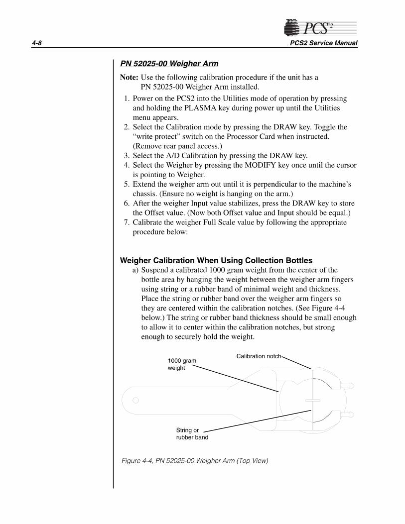
4-8 PCS2 Service Manual
PN 52025-00 Weigher Arm
Note: Use the following calibration procedure if the unit has a PN 52025-00 Weigher Arm installed.
1. Power on the PCS2 into the Utilities mode of operation by pressingand holding the PLASMA key during power up until the Utilitiesmenu appears.
2. Select the Calibration mode by pressing the DRAW key. Toggle the“write protect” switch on the Processor Card when instructed.(Remove rear panel access.)
3. Select the A/D Calibration by pressing the DRAW key.4. Select the Weigher by pressing the MODIFY key once until the cursor
is pointing to Weigher.5. Extend the weigher arm out until it is perpendicular to the machine’s
chassis. (Ensure no weight is hanging on the arm.)6. After the weigher Input value stabilizes, press the DRAW key to store
the Offset value. (Now both Offset value and Input should be equal.)7. Calibrate the weigher Full Scale value by following the appropriate
procedure below:
Weigher Calibration When Using Collection Bottlesa) Suspend a calibrated 1000 gram weight from the center of the
bottle area by hanging the weight between the weigher arm fingersusing string or a rubber band of minimal weight and thickness.Place the string or rubber band over the weigher arm fingers sothey are centered within the calibration notches. (See Figure 4-4below.) The string or rubber band thickness should be small enoughto allow it to center within the calibration notches, but strongenough to securely hold the weight.
1000 gramweight
String orrubber band
Calibration notch
Figure 4-4, PN 52025-00 Weigher Arm (Top View)

Chapter 4, Calibration 4-9
Note: When using a 1000 gram weight that can be fit within the weigherarm’s fingers, the weight may be positioned inside the arm’sfingers, provided the weight’s neck is equal to or greater than thatof the collection bottle.
b) Once the Input has stabilized, press the RETURN key to store theweigher Full Scale value. (Now both Full Scale and Input valuesshould be equal.)
Weigher Calibration When Using Collection Bagsa) Suspend a calibrated 1000 gram weight centered between the bag
pins, using a string or rubber band of minimal weight and thicknessplaced on both pins.
b) Once the Input has stabilized, press the RETURN key to store theweigher Full Scale value. (Now both Full Scale and Input valuesshould be equal.)
Weigher Calibration When Using Collection Bottles and BagsWhen utilizing collection bottles and bags, the weigher should becalibrated using the bottle calibration method (see above) or it can berecalibrated to the specific type of collection device prior to its use.
8. Remove the 1000 gram weight from the weigher arm.9. Exit A/D Calibration by pressing the STOP key, and then exit
Calibration by pressing the STOP key again. Toggle the “writeprotect” switch on the Processor Card when instructed, then replacethe rear access panel. Pay particular attention to prevent disconnectionor kinking of the pneumatic lines around the compressor and cuffconnector.
10. Exit Utilities by pressing the STOP key.
DPM1. Power on the PCS2 into the Utilities mode of operation by pressing
and holding the PLASMA key during power up until the Utilitiesmenu appears. The PCS2 must be powered on a minimum of 15minutes before proceeding with calibration.
2. Select Calibration using the MODIFY PROGRAM and DRAW keys.Toggle the write protect switch on the Processor Card wheninstructed. (Remove rear access panel.)
3. Select A/D Calibration by pressing the DRAW key, then select DPMby pressing the MODIFY PROGRAM key.
4. Press the DRAW key to store the DPM Offset value.
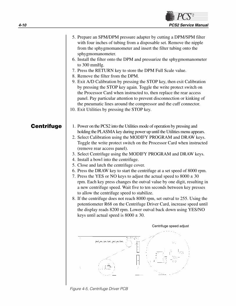
4-10 PCS2 Service Manual
Centrifuge
5. Prepare an SPM/DPM pressure adapter by cutting a DPM/SPM filterwith four inches of tubing from a disposable set. Remove the nipplefrom the sphygmomanometer and insert the filter tubing onto thesphygmomanometer.
6. Install the filter onto the DPM and pressurize the sphygmomanometerto 300 mmHg.
7. Press the RETURN key to store the DPM Full Scale value.8. Remove the filter from the DPM.9. Exit A/D Calibration by pressing the STOP key, then exit Calibration
by pressing the STOP key again. Toggle the write protect switch onthe Processor Card when instructed to, then replace the rear accesspanel. Pay particular attention to prevent disconnection or kinking ofthe pneumatic lines around the compressor and the cuff connector.
10. Exit Utilities by pressing the STOP key.
1. Power on the PCS2 into the Utilities mode of operation by pressing andholding the PLASMA key during power up until the Utilities menu appears.
2. Select Calibration using the MODIFY PROGRAM and DRAW keys.Toggle the write protect switch on the Processor Card when instructed(remove rear access panel).
3. Select Centrifuge using the MODIFY PROGRAM and DRAW keys.4. Install a bowl into the centrifuge.5. Close and latch the centrifuge cover.6. Press the DRAW key to start the centrifuge at a set speed of 8000 rpm.7. Press the YES or NO keys to adjust the actual speed to 8000 ± 30
rpm. Each key press changes the outval value by one digit, resulting ina new centrifuge speed. Wait five to ten seconds between key pressesto allow the centrifuge speed to stabilize.
8. If the centrifuge does not reach 8000 rpm, set outval to 255. Using thepotentiometer R68 on the Centrifuge Driver Card, increase speed untilthe display reads 8200 rpm. Lower outval back down using YES/NOkeys until actual speed is 8000 ± 30.
Figure 4-5, Centrifuge Driver PCB
Centrifuge speed adjust

Chapter 4, Calibration 4-11
9. Press the SAVE PROGRAM key to save the outval value and changethe centrifuge set speed to 3000 rpm.
10. Press the YES or NO keys to adjust the actual speed to 3000 ± 30rpm. Each key press changes the outval value by one digit, resulting ina new centrifuge speed. Wait five to ten seconds between key pressesto allow the centrifuge speed to stabilize.
11. Press the SAVE PROGRAM key to save the outval value (thedisplayed outval value may change when the SAVE PROGRAM keyis pressed).
12. Press the RETURN key to cycle the centrifuge speed from 8000,7000, 5650, 4800, and 3000. Verify that the actual speeds are within100 rpm of the set speeds.
13. Press the MODIFY PROGRAM key to exit the CentrifugeCalibration, then press the STOP key to exit Calibration. Toggle thewrite protect switch on the Processor Card when instructed to, thenreplace the rear access panel. Pay particular attention to preventdisconnection or kinking of the pneumatic lines around thecompressor and the cuff connector.
14. Exit Utilities by pressing the STOP key.
1. Power on the PCS2 into the Utilities mode of operation by pressingand holding the PLASMA key during power up until the Utilitiesmenu appears.
2. Remove filters or tubing from the DPM, then select Calibration using theMODIFY PROGRAM and DRAW keys. Toggle the write protect switchon the Processor Card when instructed. (Remove rear access panel.)
3. Select Safety System using the MODIFY PROGRAM and DRAW keys.4. Press the DRAW key to save the new high value and verify that the
value is between 3260 – 4080.5. Change the pressure status to low by pressing the SAVE PROGRAM
key.6. Press the RETURN key to save the new low value and verify that the
value is between 1265 – 1620.7. Exit Safety System Calibration by pressing the MODIFY PROGRAM
key, then exit Calibration by pressing the STOP key. Toggle the writeprotect switch on the Processor Card when instructed to. Then replacethe rear access panel. Pay particular attention to prevent disconnectionor kinking of the pneumatic lines around the compressor and the cuffconnector.
8. Exit Utilities by pressing the STOP key.
Safety System

Overall Cosmetic Check1. Check shipping carton for any sign of damage.2. Inspect PCS2, especially in areas where damage to the shipping
carton, if any, was found.3. Inspect PCS2 cabinet and mounted assemblies for imperfections.
Internal Workmanship1. Remove front and rear access panels to gain access to internal
components.2. Check all electrical connections including ground straps.3. Check all pneumatic lines for evidence of kinked lines.4. Check for loose or missing mounting hardware.
Language Configuration1. Power on the PCS2 in the Utilities mode of operation by pressing and
holding the PLASMA key while switching the power on. Hold thePLASMA key until the Utilities menu appears on the display.
2. Select Configuration on the Utilities menu by pressing the MODIFYPROGRAM key until the arrow points to Configuration, then pressthe DRAW key. Toggle the write protect switch on the Processor Cardwhen instructed. (Remove rear access panel.)
3. Press the MODIFY PROGRAM key until the arrow points toLanguage.
4. Select Language by pressing the DRAW key.5. Press the MODIFY PROGRAM key until the arrow points to the
language desired.6. Select the language by pressing the DRAW key.7. Press the STOP key to exit Language Configuration
Chapter 5Installation and Configuration
InitialInspection
Configurationof Protocol
Parameters

5-2 PCS2 Service Manual
8. Press the STOP key again to exit Configuration. Toggle the writeprotect switch on the Processor Card when instructed, then replace therear panel.
9. Exit Utilities by pressing the STOP key.
Protocol Selection1. Power on the PCS2 in the Utilities mode of operation by pressing and
holding the PLASMA key while switching the power on. Hold thePLASMA key until the Utilities menu appears on the display.
2. Select Configuration on the Utilities menu by pressing the MODIFYPROGRAM key until the arrow points to Configuration, then pressthe DRAW key. Toggle the write protect switch on the Processor Cardwhen instructed. (Remove rear access panel.)
3. Press the MODIFY PROGRAM key until the arrow points toProtocols.
4. Select Protocols by pressing the DRAW key.The following graphic represents the Protocol Selection screen.
ACCESSIBLE PROTOCOLS→∗ PPP WITHOUT SALINE COMP.
PPP WITH SALINE COMP.PPP AND LEUKOCYTEPPP WITH SALINE & CLOSED SET
PRESS YES/NO TO TOGGLE
Note: Protocols with an asterisk next to them will be available to theoperator before each procedure. The PPP and Leukocyte Protocol isused to collect leukocytes in addition to plasma. The PPP withSaline and Closed Set Protocol is designed to be used with a“closed set” disposable set and will return saline after each cycle.This should not be used in the Source Plasma application.
5. Use the MODIFY PROGRAM key to move the arrow to the desiredprotocol.
6. Press the YES key to select a desired protocol. (This makes theselected protocol available to the operator.)
7. Press the NO key to deselect a desired protocol. (This makes thedeselected protocol unavailable to the operator.)
The following table has been included to aid centers in the protocolconfiguration of their machines.
Chapter 5, Installation and Configuration 5-3
Center Protocol Select
Always reinfuse saline PPP with Saline Comp.
Never reinfuse saline PPP without Saline Comp.
Sometimes reinfuse saline PPP with Saline Comp.
PPP without Saline Comp.
8. When all desired protocols are selected, press the STOP key to exitProtocol Configuration.
9. Press the STOP key again to exit Configuration. Toggle the writeprotect switch on the Processor Card when instructed, and replace therear panel.
10.Exit Utilities by pressing the STOP key.
Machine Settings
Note: Machine settings do not require configuration unless the RS232port is being utilized with an external communications device.
1. Power on the PCS2 in the Utilities mode of operation by pressing andholding the PLASMA key while switching the power on. Hold thePLASMA key until the Utilities menu appears on the display.
2. Select Configuration on the Utilities menu by pressing the MODIFYPROGRAM key until the arrow points to Configuration, then pressthe DRAW key. Toggle the write protect switch on the Processor Cardwhen instructed. (Remove rear access panel.)
3. Press the MODIFY PROGRAM key until the arrow points toMachine.
4. Select Machine by pressing the DRAW key.5. Set the RS232 Board Type by using the YES and NO keys. The
machine defaults to “Standard.” Leave the setting at Standard unlessfurther instructed. Press the MODIFY PROGRAM key after theRS232 Board has been selected.
6. Set the RS232 Device by using the YES and NO keys. The settingoptions are: Network, Disk Drive or Printer. This setting does notrequire configuration unless one of the three configurable externaldevices are being utilized. Press the MODIFY PROGRAM key afterthe RS232 Device has been selected.
7. Set the RS232 Baud Rate by using the YES and NO keys. This BaudRate defaults to 19200. This setting is dependent on the type ofRS232 Device being utilized and does not require configuration if noexternal RS232 Device is being used.
8. Press the STOP key to exit Machine Settings.

5-4 PCS2 Service Manual
9. Press the STOP key again to exit Configuration. Toggle the writeprotect switch on the Processor Card when instructed and replace therear panel.
10.Exit Utilities by pressing the STOP key.
Serial Number Configuration1. Power on the PCS2 in the Utilities mode of operation by pressing and
holding the PLASMA key while switching the power on. Hold thePLASMA key until the Utilities menu appears on the display.
2. Select Configuration on the Utilities menu by pressing the MODIFYPROGRAM key until the arrow points to Configuration, then pressthe DRAW key. Toggle the write protect switch on the Processor Cardwhen instructed. (Remove rear access panel.)
3. Press the MODIFY PROGRAM key until the arrow points to Serial #.4. Select Serial # by pressing the DRAW key.
The following graphic represents the Serial # screen:
MACHINE SERIAL #
Machine SERIAL # 00A000^
5. Use the “YES” and “NO” keys to change the digit or characterselected, as indicated by the “^” cursor. Use the “MODIFY” key toadvance the cursor to the next digit/character. Change all digits orcharacters until the display serial number matches the machine serial.
6. Press the STOP key to exit Serial # Configuration.7. Press the STOP key again to exit Configuration. Toggle the write
protect switch on the Processor Card when instructed and replace therear panel.
8. Exit Utilities by pressing the STOP key.
Collection Weight Configuration1. Power on the PCS2 in the Utilities mode of operation by pressing and
holding the PLASMA key while switching the power on. Hold thePLASMA key until the Utilities menu appears on the display.
2. Select Configuration on the Utilities menu by pressing the MODIFYPROGRAM key until the arrow points to Configuration, then pressthe DRAW key. Toggle the write protect switch on the Processor Cardwhen instructed. (Remove rear access panel.)
Chapter 5, Installation and Configuration 5-5
3. Press the MODIFY PROGRAM key until the arrow points to DrawCycle.
4. Select Draw Cycle by pressing the DRAW key.5. Set the LOW weight by using the YES key to increase and the NO
key to decrease the weight. Press the MODIFY PROGRAM key whenthe desired LOW weight has been reached.
6. Set the MID weight by using the YES key and NO key. Press theMODIFY PROGRAM key when the desired MID weight has beenreached.
7. Set the HIGH weight by using the YES key and NO key. Press theMODIFY PROGRAM key when the desired HIGH weight has beenreached. The screen will then display the “Suction Compens. wt.”setting; leave the setting at 1.
8. Press the MODIFY PROGRAM key to set the Plasma Unit ofMeasurement to the desired setting. Press the YES key to selectVolume and the NO key to select “Weight” (The default value isWeight). Proceed to Step 10 if “Weight” is selected.
9. Press the MODIFY PROGRAM key after selecting “Volume” to setthe Plasma Density [%]. Use the YES and NO key to set the PlasmaDensity [%] in accordance to the center SOP (The default value is1026).
10.Press the MODIFY PROGRAM key until Duration in Statistics isdisplayed. Use the YES key to ENABLE and the NO key to DISABLE(The default value is Enable). Selecting ENABLE will display theprocedure time in the Procedure Statistics Screen.
11.Press the STOP key to exit Draw Cycle Configuration.12.Press the STOP key again to exit Configuration. Toggle the write
protect switch on the Processor Card when instructed, and then replacethe rear panel.
13. Exit Utilities by pressing the STOP key.
Bowl Configuration1. Power on the PCS2 in the Utilities mode of operation by pressing and
holding the PLASMA key while switching the power on. Hold thePLASMA key until the Utilities menu appears on the display.
2. Select Configuration on the Utilities menu by pressing the MODIFYPROGRAM key until the arrow points to Configuration, then pressthe DRAW key. Toggle the write protect switch on the Processor Cardwhen instructed (remove rear access panel).
3. Press the MODIFY PROGRAM key until the arrow points to HSBowl, then press the DRAW key
4. Press the MODIFY PROGRAM key until HS Bowl is displayed. Usethe Yes key to ENABLE and the NO key to DISABLE (The default isDisable).

5. Press the STOP key to exit HS Bowl.6. Press the STOP key again to exit Configuration. Toggle the write
protect switch on the Processor Card when instructed, and thenreplace the rear panel.
7. Exit Utilities by pressing the STOP key.
Valves Test1. Power on the PCS2 into the Utilities mode of operation by pressing
and holding the PLASMA key during power up until the Utilitiesmenu appears.
2. Select Diagnostics on the Utilities menu by pressing the MODIFYPROGRAM key until the arrow points to Diagnostics, then press theDRAW key.
3. Select the Valves test by using the MODIFY PROGRAM key to movethe arrow to “Valves” test and the DRAW key to execute.
4. Open all three valves by pressing the SALINE, PLASMA, and CUFFkeys.
5. Insert tubing from a PCS2 harness set, LN 620, into each valve andpress the DRAW key to start cycling the valves.
6. Allow valves to cycle for at least one minute, then press the STOPkey. Verify that at the end of one minute, no errors have accumulatedin the error log. If errors exist, determine which valve is causing theerror by running the cycle test again. Isolate problem to power(Eng./De-eng.) position switch (Open/Closed), or valve current (High-current). Refer to Chapter 6, Troubleshooting.
7. Exit the Valves test by pressing the MODIFY PROGRAM key.
Weigher Test1. Power on the PCS2 in the Utilities mode of operation by pressing and
holding the PLASMA key while switching the power on. Hold thePLASMA key until the Utilities menu appears on the display.
2. Select Diagnostics on the Utilities menu by pressing the MODIFYPROGRAM key until the arrow points to Diagnostics, then press theDRAW key.
3. Be sure the weigher arm is fully extended with nothing hanging on it.Select the weigher test on the Diagnostics menu by pressing theMODIFY PROGRAM key, then press the DRAW key.
4. Verify the displayed weight is ZERO ±1.5. Hang the following calibrated weights on the weigher and verify that
the displayed weight is within the defined specification.
• 1000 ± 5 grams
5-6 PCS2 Service Manual
Testing

Chapter 5, Installation and Configuration 5-7
6. Remove the weights and verify that the displayed weight returns toZERO ±1.
7. If calibration is required, refer to Chapter 4.8. Exit the weigher test by pressing the MODIFY PROGRAM key.
DPM Sensor Test1. Be sure no filters are connected to the DPM and SPM. Select the
Pressure test using the MODIFY PROGRAM and DRAW keys.
Note: List Number 06002-110-NA machines do not have the SPM.
2. Verify that the DPM offset is within the range of 1984 to 2112. If outof range, DPM may need to be replaced.
3. Grasp the DPM white luer plunger and twist counterclockwise whilesliding in the plunger. Verify both interlock switch status indicatorschange to IN. Release the plunger and verify that both indicatorsreturn to OUT.
4. Grasp the DPM white luer plunger and twist clockwise while slidingin the plunger. Verify both interlock switch status indicators change toIN. Release the plunger and verify that both indicators return to OUT.
5. Install a DPM filter with about 4" of tubing onto the DPM. Connect acalibrated sphygmomanometer or equivalent device to the filtertubing. Pressurize the DPM to 300 mmHg and verify that thedisplayed pressure reading is within the range of 292 to 308 mmHg.
6. If calibration is required, refer to Chapter 4.
Cuff Test1. Install a cuff adaptor tubing with a sphygmomanometer (or
equivalent) attached into the rear panel cuff connector.2. Turn the cuff compressor on by pressing the CUFF key.3. Verify the cuff inflates to 50 ± 5 mmHg.4. Use the YES key to increase the cuff pressure to 100.5. Verify the cuff inflates to100 ± 10 mmHg.6. If calibration is required, refer the Chapter 4, Calibration.Exit the Pressure test by pressing the MODIFY PROGRAM key.
Display Test1. Select the Display test using the MODIFY PROGRAM and DRAW keys.2. Verify that all pixels are lit on display, then press DRAW.3. Verify that a character set is displayed and no characters are deformed
or missing.4. Exit the Display test by pressing the MODIFY PROGRAM key.

Keyboard Test1. Select the Keyboard test using the MODIFY PROGRAM and DRAW
keys.2. Press each key (save MODIFY PROGRAM key for last) and verify
that LED extinguishes (if equipped) and Key Pressed value indicatesthe correct key name.
3. Press the MODIFY PROGRAM key to exit the Keyboard test.
Centrifuge TestingFluid Sensor Test1. Select the Centrifuge test in Diagnostics using the MODIFY
PROGRAM and DRAW keys.2. Open the centrifuge cover and place a moist paper towel or cotton
swab on the fluid sensor located in the centrifuge well. Verify that theSPILL value changes to TRUE.
3. Remove moisture and wipe dry. Verify that the SPILL value changesto FALSE.
Centrifuge Cover & Lock Function Test1. Close centrifuge cover and slowly rotate the cover lock until the
COVER value changes from UNLOCKED to LOCKED. Verify thatthe cover knob can be turned an additional 3/8" to 5/8" after the coverlock switches activate.
2. If adjustment is required, refer to the Chapter 2, Machine PartReplacement Reference.
Centrifuge Speed and Bowl Vibration Test1. Install a bowl partially filled with water (approximately 2/3 full) into
the centrifuge. Close and lock the centrifuge cover.2. Start the centrifuge by pressing the DRAW key. Verify the Centrifuge
Speed stabilizes to 7000 ± 100 rpm.3. If calibration is required, refer to Chapter 4, Calibration.4. As the centrifuge is spinning, observe the air/water interface in the
bowl and listen for any signs of centrifuge contract with the chassis.Verify that the air/water interface never becomes discontinuous,indicating excessive vibration.
5. If excessive vibration or noise is observed, refer to the Machine PartReplacement Chapter to realign the centrifuge.
6. Press the STOP key to stop the centrifuge and remove the bowl fromthe centrifuge.
7. Exit the centrifuge test by pressing the MODIFY PROGRAM key.
5-8 PCS2 Service Manual

Chapter 5, Installation and Configuration 5-9
Donor Lights Test1. Select the Donor Lights test using the MODIFY PROGRAM and
DRAW keys.2. Verify that all LEDs light and extinguish when instructed.3. Exit the Donor Lights test by pressing the MODIFY PROGRAM key.
Line Sensor Test1. Be sure the PCS2 has been powered on for at least 15 minutes before
proceeding with this test.2. Select the Transducers test using the MODIFY PROGRAM and
DRAW keys.3. Verify that no tubing is installed in the line sensor, and that the digital
reading for the line sensor signal is between 2866 and 3276.4. Slide a black non-reflective surface into the line sensor tubing slot.
(Dull paper with dull black marker on both sides works well for this)Verify that the line sensor signal drops to between 0 and 103.
5. If calibration is required, refer to Chapter 4.
Bowl Optics Signal Test1. Be sure the PCS2 has been powered on for at least 15 minutes before
proceeding with this test.2. Select the Transducer test using the MODIFY PROGRAM and
DRAW keys.3. Inspect the optic window for contamination and clean before
measuring the optics signal.4. Remove the gray card from the envelope in the Gray Card
Replacement Kit.5. Make a note of the Correction Factor written on the back of the gray
card.6. Insert the gray card into the optic alignment fixture so that the arrow
on the back points up into the optic fixture.
Note: If the optic alignment fixture has a gray card installed, remove thegray card and discard. The gray card used in the optic alignmentfixture must be uncontaminated by light or material.
Ensure the white backing of the gray card is not “yellow.”
Ensure the gray measuring surface is not physically damaged.
Ensure the gray card is less than one year older than the dateprinted on the back of the card.
7. a) If testing the optics signal to a digital value, select the Transducertest in Diagnostics.

b) If testing the optics signal to an analog voltage, connect a digitalvoltage meter, (greater than 3½ digit resolution), to J105 (top plug)pin 9 (signal) and pin 5 (ground) on the Processor Card.
8. Ensure the centrifuge chuck is empty. Verify the average analog ordigital reading for the bowl optics offset signal is between 1 and 82digital units or -0.10 to +0.10 Vdc.
9. Install the optic fixture ETD 5060 in the centrifuge and rotate it untilthe optic beam is centered on the gray card.
10.Close the centrifuge cover to allow the cover’s bowl collars to lockaround the optic fixture’s square alignment tabs.
11.Make a note of the actual digital or analog voltage optic gray cardreading.
12.Use the Correction Factor printed on the back of the gray card and theformula below to calculate the optic gain being measured. Ensure thecalculated optic reading with Correction Factor is between 2295 and3278 digital units or +2.8 to 4.0 Vdc.
Use the following formula to determine the optic gain with CorrectionFactor:
Optic Digital Gain with Correction Factor = Actual Digital Gray Card Reading ÷Correction Factor
or
Optic Voltage Gain with Correction Factor = Actual Optic Gray Card Reading(Vdc) ÷ Correction Factor
Example:
The actual gray card reading is 2397 digital units or 2.926 Vdc
The Correction Factor on the back of the gray card = 0.829
Optic Digital Gain with Correction Factor = 2397 ÷ 0.829 = 2891 digital unitsor
Optic Voltage Gain with Correction Factor = 2.926 Vdc ÷ 0.829 = 3.53 Vdc
13.If calibration is required, refer to the Bowl Optics Signal Calibration inChapter 4.
Note: The bowl optics signal test (operational) range described abovediffers from the bowl optics signal calibration range in theCalibration Chapter. The optics calibration range is utilized toadjust the optics gain if it is found to be outside the acceptable opticcalibration test range.
5-10 PCS2 Service Manual
Chapter 5, Installation and Configuration 5-11
When documenting the optic signal value, ensure the voltagerecorded is the calculated optic signal value, not the actual graycard reading. In the above example in step 11, the optic signal valuerecorded would be 2891 digital or +3.53 Vdc.
Warning!
The Correction Factors used in the above calculations are examplevalues only. Each gray card is individually indexed and theCorrection Factor may vary for each card. The Correction Factorfrom the actual card being used must be incorporated into theoptics signal calibration and testing calculations.
Air Detector Test1. Select the Air Detector test using the MODIFY PROGRAM and
DRAW keys.2. Place fluid-filled tubing in air detector under test as requested, verify
that the air detector LED lights, and press the DRAW key asrequested.
3. Repeat test for each air detector as asked. When the last air detectorhas been tested, a screen will appear showing the status of the four airdetector signals. Confirm that each air detector can see fluid and airby inserting a piece of fluid-filled tubing into each air detector whilemonitoring the Polled and Latched signals.
4. If an air detector fails the testing, refer to the TroubleshootingChapter.
5. Exit the Air Detector test by pressing the MODIFY PROGRAM key.
PCS2 Functional Test1. Exit Utilities by pressing the STOP key. The PCS2 will reboot and
execute the system start-up sequence. Respond to any questions orwarning as the test progresses. Select a new procedure if prompted.
2. Ensure a cuff is installed in the rear panel connector and all fourexhaust fans are operating and blowing air out of the rear panel.
3. Lock and unlock centrifuge cover as prompted.4. Verify the PCS2 advances to the Weigher Test screen. With no weight
on the weigher, verify the displayed weight is ZERO ± 1 gram. If it isoutside this range, press the DRAW key to tare the weigher. Hang a1000g calibrated weight on the weigher. Verify the displayed weightis 1000 ± 5 grams.
5. Remove the weight and verify the displayed weight returns to ZERO± 1 gram.
!

6. Press the YES key and verify the Install Disposable screen isdisplayed.
7. At Install Disposable screen perform the following:• Install partially water-filled bowl in the centrifuge and lock the
centrifuge cover.
• Install a DPM filter in the DPM
• Floss a segment of clear LN620 harness tubing through the linesensor.
Verify the PCS2 display advances to the Load Pump/Test Centrifugescreen.
8. Press the PRIME key and verify the following:• Both pumps turn clockwise for a few seconds, then stop.
• The centrifuge spins for a few seconds, then stops.9. Press the YES key and verify the Plasma Collection Weight Selection
screen is displayed.10.Press the MODIFY key and verify the Saline Substitution screen is
displayed.
Note: This screen will only be displayed is the saline option isprogrammed. If the saline option is not programmed, verify thePRIME screen is displayed and proceed to step 12.
11.Press the NO key and verify the PRIME screen is displayed.12.Install fluid-filled tubing in the AC, DLAD1 and DLAD2 and then
press the PRIME key. Verify machine advances to the Ready screen.13.Install fluid-filled tubing in the BLAD.14.Press the Draw key and verify the both pump are turning clockwise,
the centrifuge is spinning and the cuff inflates. Also verify the donorand plasma valves open.
15.After a few moments, the 'No Pressure Change At DPM' message willbe displayed, press the DRAW key to continue.
16.Observe the air/water interface in the bowl as the centrifuge isspinning and listen for any signs of the centrifuge contacting thecabinet. Verify the air/water interface never becomes discontinuous,indicating excessive vibration.
17.Press the STOP key. Verify the centrifuge and both pumps stop and allvalves close.
18.Press the RETURN key and verify the End Procedure Option screen isdisplayed.
19.Press the YES key and verify the blood pump turns counterclockwiseand the AC pump is not turning. Also verify the donor valve opensimmediately and the plasma valve opens shortly thereafter.
20.Press the STOP key after a few moments and verify the Ready isdisplayed.
21.Press the STOP key again and verify the Abort Procedure screen isdisplayed.
5-12 PCS2 Service Manual
Chapter 5, Installation and Configuration 5-13
22.Press the YES key to abort the procedure and verify the AbortProcedure Confirmation screen is displayed.
23.Press the DRAW key to abort the procedure and verify the ProcedureStatistics screen is display.
24.Remove the test disposable set and verify the machine advances to theSystems Test screen.
Leakage Current1. Plug the PCS2 into the Leakage Tester (Dale Technologies LT544D
Lite or equivalent).2. Plug the Leakage Tester into a grounded electrical outlet.3. Set the meter switch settings as follows:
• Leakage
• Neutral Closed
• Polarity Normal4. Turn on the PCS2.5. Note the reading in microamperes on the meter.6. Depress the GND switch on the meter.7. Change the Polarity switch from Normal to Reverse.8. Verify the readings do not exceed 100 microamperes at 120 VAC and
500 microamperes at 240 VAC.
Ground Continuity1. Change the meter mode to RESISTANCE.2. Plug the ground wire (coiled wire with clip) into the grounding socket
on the Leakage Meter.3. Attach the clip to the following exposed metal locations. Verify that
there is continuity.• Pump - rotor screws
• Rear Panel hardware
• Front panel hardware
• Pinch valve plungers4. Verify the highest reading is less than 1 Ohm.

Source Plasma Customers OnlyWhen machines are transferred between center locations, calibrationtesting and configuration should be performed prior to placing themachines into service. The calibration testing and configuration stepsoutlined in Chapter 5, excluding Leakage Current and Ground Continuity,should be performed. The testing and configuration must be performed atthe center it is being transferred to. The PCS2 Machine TransferVerification Sheet, on page 5-15, should be completed and kept in thecenter’s machine log.
5-14 PCS2 Service Manual
MachineTransfers

Chapter 5, Installation and Configuration 5-15
PCS2 Machine Transfer Verification Form
Customer Name: City/State:
PCS-2 Serial #
VALVES Functional Yes No
WEIGHER Zero Reading0 gm ± 1
1000 gm ± 5
PRESSURE DPM Offset (1984 - 2112)
300 mmHg ± 8
CUFF 50 mmHg ± 5
100 mmHg ± 10
DISPLAY Functional Yes No
KEYBOARD Functional Yes No
CENTRIFUGE SPEED Set Speed Actual Speed
7000 RPM ± 100
Cover Lock Functional Yes No
Bowl Vibration Functional Yes No
Spill Detect Functional Yes No
Donor Lights Functional Yes No
TRANSDUCERS OPTICS Aim (Yes if Adjusted) Yes No
Open (1-82 or 0 V ± 0.10)
Grey Card
(2295- 3278 or 2.8 - 4.0 V)
LINE SENSOR Open (2866 - 3276)
Black (0-103)
AIR DETECTOR ACAD Functional Yes No
BLAD Functional Yes No
DLAD-1 Functional Yes No
DLAD-2 Functional Yes No
FANS Functional Yes No
Biohazardous Waste Bag Attached Yes No
Program RevisionCuff
Weigher
Circle if adjusted DPM
Centrifuge
Optics Voltage
Line Sensor
Performed by: Print Name:
Date:

Chapter 6Troubleshooting
The purpose of this chapter is to provide troubleshooting assistance forsolving problems associated with the PCS2. The scope of this chapterfocuses on solving electrical, mechanical, and performance relatedproblems.
Note: When troubleshooting machines, it is helpful to use parts from aworking PCS2 unit to verify faults and isolate the questionablecomponent. Once the faulty component is isolated, notify theHaemonetics Hot Line at 800-356-3506. If at all possible,Haemonetics recommends the substitute part be returned to theoriginal machine.
The PCS2 operating protocols use refined technologies which rely onmany variables to function. If possible, procure PCS2 operational trainingbefore investigating system performance or product quality issues.
The messages reported by the PCS2 are very specific and provide usefuldiagnostic information about the problem. There are over 100 diagnosticmessages which can be generated by the processor card, and severalhundred combinations of safety fault codes which can be generated by thesafety card. Most hardware or electrical failures will be reported by onesystem or the other.
The inventory of messages the PCS2 has to report information to the useris vast. This functionality is an important diagnostic tool when trying tounderstand a problem.
MESSAGES
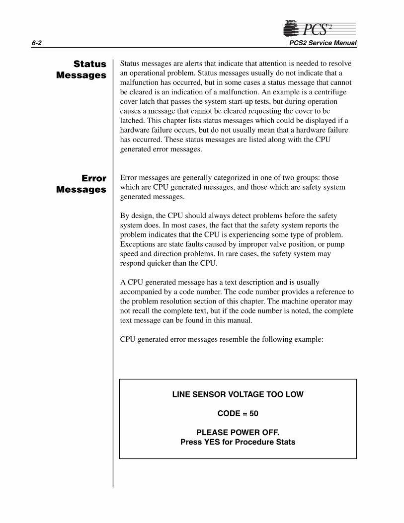
6-2 PCS2 Service Manual
Status messages are alerts that indicate that attention is needed to resolvean operational problem. Status messages usually do not indicate that amalfunction has occurred, but in some cases a status message that cannotbe cleared is an indication of a malfunction. An example is a centrifugecover latch that passes the system start-up tests, but during operationcauses a message that cannot be cleared requesting the cover to belatched. This chapter lists status messages which could be displayed if ahardware failure occurs, but do not usually mean that a hardware failurehas occurred. These status messages are listed along with the CPUgenerated error messages.
Error messages are generally categorized in one of two groups: thosewhich are CPU generated messages, and those which are safety systemgenerated messages.
By design, the CPU should always detect problems before the safetysystem does. In most cases, the fact that the safety system reports theproblem indicates that the CPU is experiencing some type of problem.Exceptions are state faults caused by improper valve position, or pumpspeed and direction problems. In rare cases, the safety system mayrespond quicker than the CPU.
A CPU generated message has a text description and is usuallyaccompanied by a code number. The code number provides a reference tothe problem resolution section of this chapter. The machine operator maynot recall the complete text, but if the code number is noted, the completetext message can be found in this manual.
CPU generated error messages resemble the following example:
LINE SENSOR VOLTAGE TOO LOW
CODE = 50
PLEASE POWER OFF.Press YES for Procedure Stats
ErrorMessages
StatusMessages
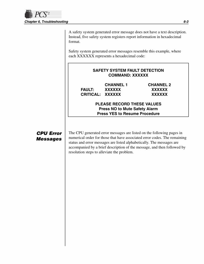
A safety system generated error message does not have a text description.Instead, five safety system registers report information in hexadecimalformat.
Safety system generated error messages resemble this example, whereeach XXXXXX represents a hexadecimal code:
The CPU generated error messages are listed on the following pages innumerical order for those that have associated error codes. The remainingstatus and error messages are listed alphabetically. The messages areaccompanied by a brief description of the message, and then followed byresolution steps to alleviate the problem.
Chapter 6, Troubleshooting 6-3
CPU ErrorMessages
SAFETY SYSTEM FAULT DETECTIONCOMMAND: XXXXXX
CHANNEL 1 CHANNEL 2FAULT: XXXXXX XXXXXXCRITICAL: XXXXXX XXXXXX
PLEASE RECORD THESE VALUESPress NO to Mute Safety Alarm
Press YES to Resume Procedure

✍ Notes ✍
6-4 PCS2 Service Manual
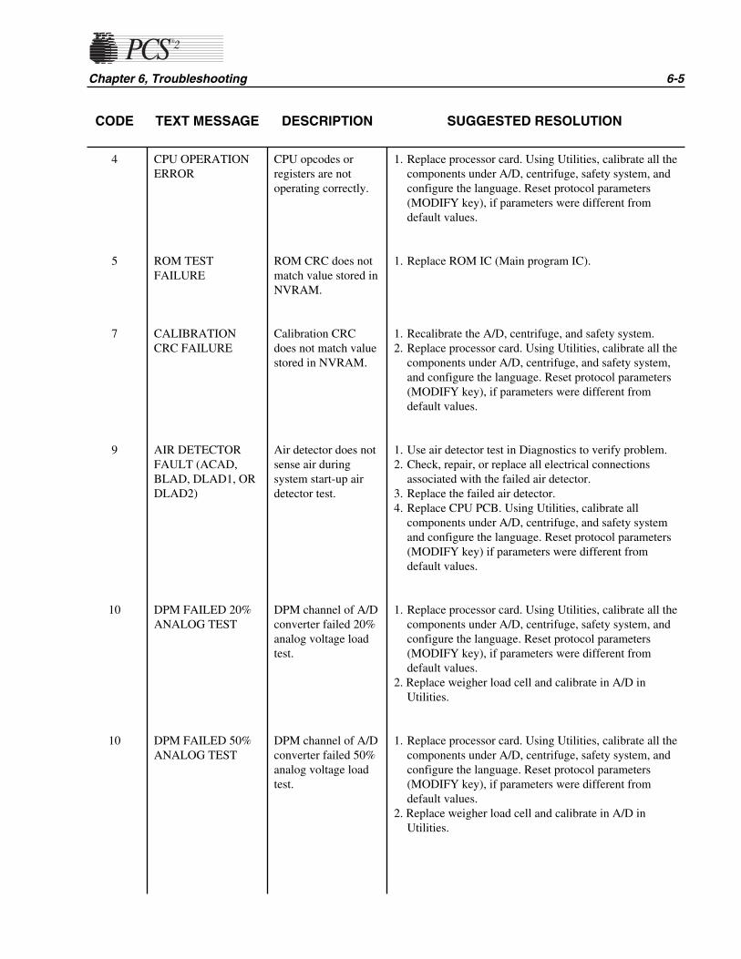
CODE TEXT MESSAGE DESCRIPTION SUGGESTED RESOLUTION
Chapter 6, Troubleshooting 6-5
4
5
7
9
10
10
CPU OPERATIONERROR
ROM TESTFAILURE
CALIBRATIONCRC FAILURE
AIR DETECTORFAULT (ACAD,BLAD, DLAD1, ORDLAD2)
DPM FAILED 20%ANALOG TEST
DPM FAILED 50%ANALOG TEST
CPU opcodes orregisters are notoperating correctly.
ROM CRC does notmatch value stored inNVRAM.
Calibration CRCdoes not match valuestored in NVRAM.
Air detector does notsense air duringsystem start-up airdetector test.
DPM channel of A/Dconverter failed 20%analog voltage loadtest.
DPM channel of A/Dconverter failed 50%analog voltage loadtest.
1. Replace processor card. Using Utilities, calibrate all thecomponents under A/D, centrifuge, safety system, andconfigure the language. Reset protocol parameters(MODIFY key), if parameters were different fromdefault values.
1. Replace ROM IC (Main program IC).
1. Recalibrate the A/D, centrifuge, and safety system.2. Replace processor card. Using Utilities, calibrate all the
components under A/D, centrifuge, and safety system,and configure the language. Reset protocol parameters(MODIFY key), if parameters were different fromdefault values.
1. Use air detector test in Diagnostics to verify problem.2. Check, repair, or replace all electrical connections
associated with the failed air detector.3. Replace the failed air detector.4. Replace CPU PCB. Using Utilities, calibrate all
components under A/D, centrifuge, and safety systemand configure the language. Reset protocol parameters(MODIFY key) if parameters were different fromdefault values.
1. Replace processor card. Using Utilities, calibrate all thecomponents under A/D, centrifuge, safety system, andconfigure the language. Reset protocol parameters(MODIFY key), if parameters were different fromdefault values.
2. Replace weigher load cell and calibrate in A/D inUtilities.
1. Replace processor card. Using Utilities, calibrate all thecomponents under A/D, centrifuge, safety system, andconfigure the language. Reset protocol parameters(MODIFY key), if parameters were different fromdefault values.
2. Replace weigher load cell and calibrate in A/D inUtilities.

6-6 PCS2 Service Manual
CODE TEXT MESSAGE DESCRIPTION SUGGESTED RESOLUTION
10
11
11
11
12
DPM FAILED 80%ANALOG TEST
SPM FAILED 20%ANALOG TEST
SPM FAILED 50%ANALOG TEST
SPM FAILED 80%ANALOG TEST
DONOR VALVEPOSITION FAULT
PLASMA VALVEPOSITION FAULT
SALINE VALVEPOSITION FAULT
DPM channel of A/Dconverter failed 80%analog voltage loadtest.
SPM channel of A/Dconverter failed 20%analog voltage loadtest.
SPM channel of A/Dconverter failed 50%analog voltage loadtest.
SPM channel of A/Dconverter failed 80%analog voltage loadtest.
Donor valve positionswitch indicates thatvalve did nottransition.
Plasma valve positionswitch indicates thatvalve did nottransition.
Saline valve positionswitch indicates thatvalve did nottransition.
1. Replace processor card. Using Utilities, calibrate all thecomponents under A/D, centrifuge, safety system, andconfigure the language. Reset protocol parameters(MODIFY key), if parameters were different fromdefault values.
2. Replace weigher load cell and calibrate in A/D inUtilities.
1. Replace processor card. Using Utilities, calibrate all thecomponents under A/D, centrifuge, safety system, andconfigure the language. Reset protocol parameters(MODIFY key), if parameters were different fromdefault values.
1. Replace processor card. Using Utilities, calibrate all thecomponents under A/D, centrifuge, safety system, andconfigure the language. Reset protocol parameters(MODIFY key), if parameters were different fromdefault values.
1. Replace processor card. Using Utilities, calibrate all thecomponents under A/D, centrifuge, safety system, andconfigure the language. Reset protocol parameters(MODIFY key), if parameters were different fromdefault values.
1. Use the valve test in Diagnostics to manually transitionvalves and monitor the valve and switch response.
2. Swap valve connections at top deck distribution card toisolate problem to valve or circuit.
3. If valve does not move, check, repair or replace allconnections associated with the appropriate valve drivecircuit.
4. Replace valve, driver card, or processor card. UsingUtilities, calibrate all the components under A/D,centrifuge, safety system, and configure the language.Reset protocol parameters (MODIFY key), if parameterswere different from default values.
5. If valve does move but is not recognized, check, repair,or replace all connections associated with the appropriatevalve position switch or replace the valve.
6. Replace driver or processor card. Using Utilities,calibrate all the components under A/D, centrifuge,safety system, and configure the language. Resetprotocol parameters (MODIFY key), if parameters weredifferent from default values.
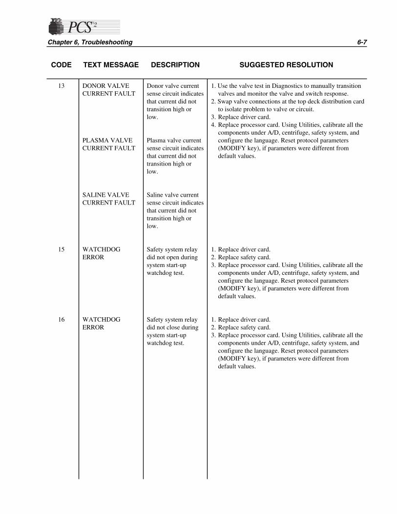
CODE TEXT MESSAGE DESCRIPTION SUGGESTED RESOLUTION
Chapter 6, Troubleshooting 6-7
13
15
16
DONOR VALVECURRENT FAULT
PLASMA VALVECURRENT FAULT
SALINE VALVECURRENT FAULT
WATCHDOGERROR
WATCHDOGERROR
Donor valve currentsense circuit indicatesthat current did nottransition high orlow.
Plasma valve currentsense circuit indicatesthat current did nottransition high orlow.
Saline valve currentsense circuit indicatesthat current did nottransition high orlow.
Safety system relaydid not open duringsystem start-upwatchdog test.
Safety system relaydid not close duringsystem start-upwatchdog test.
1. Use the valve test in Diagnostics to manually transitionvalves and monitor the valve and switch response.
2. Swap valve connections at the top deck distribution cardto isolate problem to valve or circuit.
3. Replace driver card.4. Replace processor card. Using Utilities, calibrate all the
components under A/D, centrifuge, safety system, andconfigure the language. Reset protocol parameters(MODIFY key), if parameters were different fromdefault values.
1. Replace driver card.2. Replace safety card.3. Replace processor card. Using Utilities, calibrate all the
components under A/D, centrifuge, safety system, andconfigure the language. Reset protocol parameters(MODIFY key), if parameters were different fromdefault values.
1. Replace driver card.2. Replace safety card.3. Replace processor card. Using Utilities, calibrate all the
components under A/D, centrifuge, safety system, andconfigure the language. Reset protocol parameters(MODIFY key), if parameters were different fromdefault values.

6-8 PCS2 Service Manual
CODE TEXT MESSAGE DESCRIPTION SUGGESTED RESOLUTION
17
19
20
21
22
23
WATCHDOGERROR
LOW PRESSUREERROR
LOW PRESSUREERROR
LOW PRESSUREERROR
LOW PRESSUREERROR
LOW PRESSUREERROR
Safety system did notpost fault to registerduring system start-up watchdog test.
Safety system relaydid not open duringsystem start-up lowpressure test.
Safety system relaydid not close duringsystem start-up lowpressure test.
Safety system did notpost fault to registerduring system start-up low pressure test.
DPM low pressureload test produced avalue that is out ofthe range of 1265 -1620.
DPM low pressureload test produced avalue that was ± 7%from calibratedvalue.
1. Replace safety card.2. Replace processor card. Using Utilities, calibrate all the
components under A/D, centrifuge, safety system, andconfigure the language. Reset protocol parameters(MODIFY key), if parameters were different fromdefault values.
1. Replace driver card.2. Replace safety card.
1. Replace driver card.2. Replace safety card.
1. Replace safety card.2. Replace processor card. Using Utilities, calibrate all the
components under A/D, centrifuge, safety system, andconfigure the language. Reset protocol parameters(MODIFY key), if parameters were different fromdefault values.
1. Using Diagnostics in Utilities, load the DPM for lowpressure and measure the DPM signal at P502 pin 1 ofthe backplane card. Acceptable range for low reading is1.54 - 1.98 VDC (1265 - 1620). If analog voltageexceeds range, replace DPM.
2. Replace processor card. Using Utilities, calibrate all thecomponents under A/D, centrifuge, safety system, andconfigure the language. Reset protocol parameters(MODIFY key), if parameters were different fromdefault values.
1. Recalibrate the safety system in Utilities and verify thatlow pressure digital reading is between (1265 - 1620). Ifdigital reading is out of range or grossly fluctuating,replace DPM.
2. Replace processor card. Using Utilities, calibrate all thecomponents under A/D, centrifuge, safety system, andconfigure the language. Reset protocol parameters(MODIFY key), if parameters were different fromdefault values.

CODE TEXT MESSAGE DESCRIPTION SUGGESTED RESOLUTION
Chapter 6, Troubleshooting 6-9
25
26
27
28
29
31
HIGH PRESSUREERROR
HIGH PRESSUREERROR
HIGH PRESSUREERROR
HIGH PRESSUREERROR
HIGH PRESSUREERROR
CHANNEL 1STATE ERROR
Safety system relaydid not open duringsystem start-up highpressure test.
Safety system relaydid not close duringsystem start-up highpressure test.
Safety system did notpost fault to registerduring system start-up high pressure test.
DPM high pressureload test produced avalue that is out ofthe range of 3260 -4080.
DPM high pressureload test produced avalue that was ± 7%from calibratedvalue.
Safety system relaydid not open duringsystem start-upChannel 1 state test.
1. Replace driver card.2. Replace safety card.
1. Replace driver card.2. Replace safety card.
1. Replace the safety card.2. Replace processor card. Using Utilities, calibrate all the
components under A/D, centrifuge, safety system, andconfigure the language. Reset protocol parameters(MODIFY key), if parameters were different fromdefault values.
1. Using Diagnostics in Utilities, load the DPM for highpressure and measure the DPM signal at P502 pin 1 ofthe backplane card. Acceptable range for high reading is3.98 - 4.98 VDC (3260 - 4080). If analog voltageexceeds range, replace DPM.
2. Replace processor card. Using Utilities, calibrate all thecomponents under A/D, centrifuge, safety system, andconfigure the language. Reset protocol parameters(MODIFY key), if parameters were different fromdefault values.
1. Recalibrate the safety system in Utilities and verify thathigh pressure digital reading is between (3260 - 4080). Ifthe digital reading is out of range, replace DPM.
2. Replace processor card. Using Utilities, calibrate all thecomponents under A/D, centrifuge, safety system, andconfigure the language. Reset protocol parameters(MODIFY key), if parameters were different fromdefault values.
1. Replace driver card.2. Replace safety card.
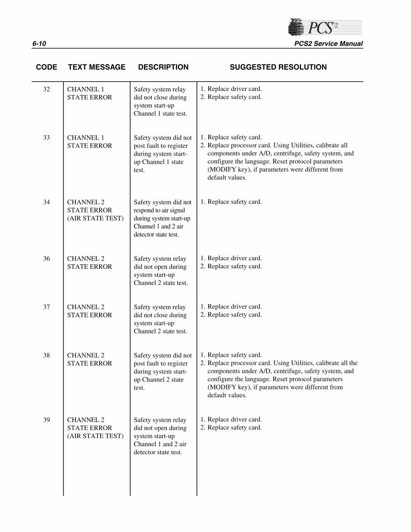
6-10 PCS2 Service Manual
CODE TEXT MESSAGE DESCRIPTION SUGGESTED RESOLUTION
32
33
34
36
37
38
39
CHANNEL 1STATE ERROR
CHANNEL 1STATE ERROR
CHANNEL 2STATE ERROR (AIR STATE TEST)
CHANNEL 2STATE ERROR
CHANNEL 2STATE ERROR
CHANNEL 2STATE ERROR
CHANNEL 2STATE ERROR (AIR STATE TEST)
Safety system relaydid not close duringsystem start-upChannel 1 state test.
Safety system did notpost fault to registerduring system start-up Channel 1 statetest.
Safety system did notrespond to air signalduring system start-upChannel 1 and 2 airdetector state test.
Safety system relaydid not open duringsystem start-upChannel 2 state test.
Safety system relaydid not close duringsystem start-upChannel 2 state test.
Safety system did notpost fault to registerduring system start-up Channel 2 statetest.
Safety system relaydid not open duringsystem start-upChannel 1 and 2 airdetector state test.
1. Replace driver card.2. Replace safety card.
1. Replace safety card.2. Replace processor card. Using Utilities, calibrate all
components under A/D, centrifuge, safety system, andconfigure the language. Reset protocol parameters(MODIFY key), if parameters were different fromdefault values.
1. Replace safety card.
1. Replace driver card.2. Replace safety card.
1. Replace driver card.2. Replace safety card.
1. Replace safety card.2. Replace processor card. Using Utilities, calibrate all the
components under A/D, centrifuge, safety system, andconfigure the language. Reset protocol parameters(MODIFY key), if parameters were different fromdefault values.
1. Replace driver card.2. Replace safety card.
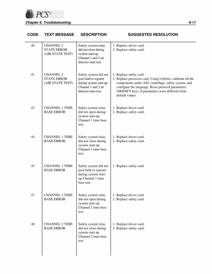
Chapter 6, Troubleshooting 6-11
CODE TEXT MESSAGE DESCRIPTION SUGGESTED RESOLUTION
40
41
43
44
45
47
48
CHANNEL 2STATE ERROR(AIR STATE TEST)
CHANNEL 2STATE ERROR(AIR STATE TEST)
CHANNEL 1 TIMEBASE ERROR
CHANNEL 1 TIMEBASE ERROR
CHANNEL 1 TIMEBASE ERROR
CHANNEL 2 TIMEBASE ERROR
CHANNEL 2 TIMEBASE ERROR
Safety system relaydid not close duringsystem start-upChannel 1 and 2 airdetector state test.
Safety system did notpost fault to registerduring system start-upChannel 1 and 2 airdetector state test.
Safety system relaydid not open duringsystem start-upChannel 1 time basetest.
Safety system relaydid not close duringsystem start-upChannel 1 time basetest.
Safety system did notpost fault to registerduring system start-up Channel 1 timebase test.
Safety system relaydid not open duringsystem start-upChannel 2 time basetest.
Safety system relaydid not close duringsystem start upChannel 2 time basetest.
1. Replace driver card.2. Replace safety card.
1. Replace safety card.2. Replace processor card. Using Utilities, calibrate all the
components under A/D, centrifuge, safety system, andconfigure the language. Reset protocol parameters(MODIFY key), if parameters were different fromdefault values.
1. Replace driver card.2. Replace safety card.
1. Replace driver card.2. Replace safety card.
1. Replace safety card.
1. Replace driver card.2. Replace safety card.
1. Replace driver card.2. Replace safety card.
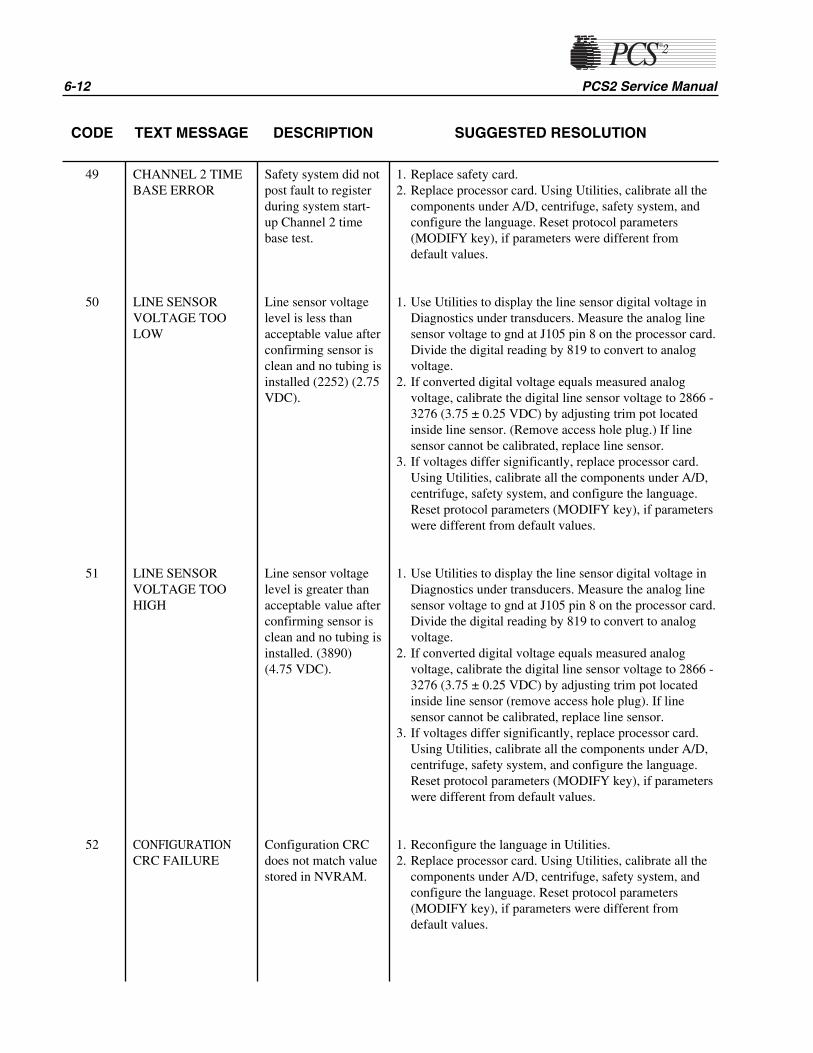
6-12 PCS2 Service Manual
CODE TEXT MESSAGE DESCRIPTION SUGGESTED RESOLUTION
49
50
51
52
CHANNEL 2 TIMEBASE ERROR
LINE SENSORVOLTAGE TOOLOW
LINE SENSORVOLTAGE TOOHIGH
CONFIGURATIONCRC FAILURE
Safety system did notpost fault to registerduring system start-up Channel 2 timebase test.
Line sensor voltagelevel is less thanacceptable value afterconfirming sensor isclean and no tubing isinstalled (2252) (2.75VDC).
Line sensor voltagelevel is greater thanacceptable value afterconfirming sensor isclean and no tubing isinstalled. (3890)(4.75 VDC).
Configuration CRCdoes not match valuestored in NVRAM.
1. Replace safety card.2. Replace processor card. Using Utilities, calibrate all the
components under A/D, centrifuge, safety system, andconfigure the language. Reset protocol parameters(MODIFY key), if parameters were different fromdefault values.
1. Use Utilities to display the line sensor digital voltage inDiagnostics under transducers. Measure the analog linesensor voltage to gnd at J105 pin 8 on the processor card.Divide the digital reading by 819 to convert to analogvoltage.
2. If converted digital voltage equals measured analogvoltage, calibrate the digital line sensor voltage to 2866 -3276 (3.75 ± 0.25 VDC) by adjusting trim pot locatedinside line sensor. (Remove access hole plug.) If linesensor cannot be calibrated, replace line sensor.
3. If voltages differ significantly, replace processor card.Using Utilities, calibrate all the components under A/D,centrifuge, safety system, and configure the language.Reset protocol parameters (MODIFY key), if parameterswere different from default values.
1. Use Utilities to display the line sensor digital voltage inDiagnostics under transducers. Measure the analog linesensor voltage to gnd at J105 pin 8 on the processor card.Divide the digital reading by 819 to convert to analogvoltage.
2. If converted digital voltage equals measured analogvoltage, calibrate the digital line sensor voltage to 2866 -3276 (3.75 ± 0.25 VDC) by adjusting trim pot locatedinside line sensor (remove access hole plug). If linesensor cannot be calibrated, replace line sensor.
3. If voltages differ significantly, replace processor card.Using Utilities, calibrate all the components under A/D,centrifuge, safety system, and configure the language.Reset protocol parameters (MODIFY key), if parameterswere different from default values.
1. Reconfigure the language in Utilities.2. Replace processor card. Using Utilities, calibrate all the
components under A/D, centrifuge, safety system, andconfigure the language. Reset protocol parameters(MODIFY key), if parameters were different fromdefault values.

Chapter 6, Troubleshooting 6-13
CODE TEXT MESSAGE DESCRIPTION SUGGESTED RESOLUTION
53
54
102
Donor Valve PositionFault
Plasma ValvePosition Fault
Saline Valve PositionFault
ExtendedConfiguration ModeNot Allowed DuringNormal PCS2 Usage.Remove Ext confjumper from J104
CENTRIFUGEOVERSPEED
Indicated valveposition switchindicates that valve isin incorrect position.
The machine sensesthat the jumper usedto gain access to theextendedconfigurationparameters has beenleft in the machine.
Centrifuge encodersignals indicate thatspindle speed is 300rpm greater than setspeed.
1. Use the valve test in Diagnostics to manually transitionvalves and monitor the valve and switch response.
2. Swap valve connections at top deck distribution card toisolate problem to valve or circuit.
3. If valve does not move, check, repair or replace allconnections associated with the appropriate valve drivecircuit.
4. Replace valve, driver card, or processor card. UsingUtilities, calibrate all the components under A/D,centrifuge, safety system, and configure the language.Reset protocol parameters (MODIFY key), if parameterswere different from default values.
5. If valve does move but is not recognized, check, repair,or replace all connections associated with theappropriate valve position switch or replace the valve.
6. Replace driver or processor card. Using Utilities,calibrate all the components under A/D, centrifuge,safety system, and configure the language. Resetprotocol parameters (MODIFY key), if parameters weredifferent from default values.
1. Remove the extended configuration jumper from J104on the processor Board.
2. Replace processor card. Using Utilities, calibrate all thecomponents under A/D, centrifuge, safety system andconfiguration. Reset protocol parameters (MODIFYkey) if parameters were different from the defaultvalues.
1. Using Utilities, display the centrifuge screen underDiagnostics. Install bowl in centrifuge. Start centrifugeand measure actual speed vs various set speeds. Ifspeeds are wrong, use calibration to calibrate centrifugespeed.
2. If speed is wrong by a gross amount, set the centrifugeset speed to 3000 rpm and measure the centrifugecommand + signal at P401 pin 18A (pin 17) on thebackplane card. Signal should be around +6.1 VDC. Ifsignal is wrong, replace the driver card.
3. Replace processor card. Using Utilities, calibrate all thecomponents under A/D, centrifuge, safety system, andconfigure the language. Reset protocol parameters(MODIFY key), if parameters were different fromdefault values.
4. If command + signal is OK, replace either the centrifugecontroller card or the centrifuge assembly.
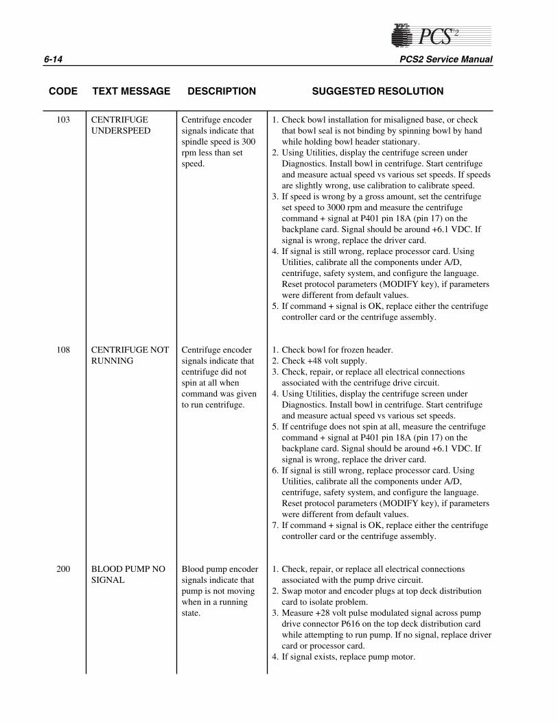
6-14 PCS2 Service Manual
CODE TEXT MESSAGE DESCRIPTION SUGGESTED RESOLUTION
103
108
200
CENTRIFUGEUNDERSPEED
CENTRIFUGE NOTRUNNING
BLOOD PUMP NOSIGNAL
Centrifuge encodersignals indicate thatspindle speed is 300rpm less than setspeed.
Centrifuge encodersignals indicate thatcentrifuge did notspin at all whencommand was givento run centrifuge.
Blood pump encodersignals indicate thatpump is not movingwhen in a runningstate.
1. Check bowl installation for misaligned base, or checkthat bowl seal is not binding by spinning bowl by handwhile holding bowl header stationary.
2. Using Utilities, display the centrifuge screen underDiagnostics. Install bowl in centrifuge. Start centrifugeand measure actual speed vs various set speeds. If speedsare slightly wrong, use calibration to calibrate speed.
3. If speed is wrong by a gross amount, set the centrifugeset speed to 3000 rpm and measure the centrifugecommand + signal at P401 pin 18A (pin 17) on thebackplane card. Signal should be around +6.1 VDC. Ifsignal is wrong, replace the driver card.
4. If signal is still wrong, replace processor card. UsingUtilities, calibrate all the components under A/D,centrifuge, safety system, and configure the language.Reset protocol parameters (MODIFY key), if parameterswere different from default values.
5. If command + signal is OK, replace either the centrifugecontroller card or the centrifuge assembly.
1. Check bowl for frozen header.2. Check +48 volt supply.3. Check, repair, or replace all electrical connections
associated with the centrifuge drive circuit.4. Using Utilities, display the centrifuge screen under
Diagnostics. Install bowl in centrifuge. Start centrifugeand measure actual speed vs various set speeds.
5. If centrifuge does not spin at all, measure the centrifugecommand + signal at P401 pin 18A (pin 17) on thebackplane card. Signal should be around +6.1 VDC. Ifsignal is wrong, replace the driver card.
6. If signal is still wrong, replace processor card. UsingUtilities, calibrate all the components under A/D,centrifuge, safety system, and configure the language.Reset protocol parameters (MODIFY key), if parameterswere different from default values.
7. If command + signal is OK, replace either the centrifugecontroller card or the centrifuge assembly.
1. Check, repair, or replace all electrical connectionsassociated with the pump drive circuit.
2. Swap motor and encoder plugs at top deck distributioncard to isolate problem.
3. Measure +28 volt pulse modulated signal across pumpdrive connector P616 on the top deck distribution cardwhile attempting to run pump. If no signal, replace drivercard or processor card.
4. If signal exists, replace pump motor.

CODE TEXT MESSAGE DESCRIPTION SUGGESTED RESOLUTION
Chapter 6, Troubleshooting 6-15
201
202
203
204
205
AC PUMP NOSIGNAL
BLOOD PUMP TOOSLOW
BLOOD PUMP TOOFAST
AC PUMP TOOFAST
RATIO FAULTTOO LOW
AC pump encodersignals indicate thatpump is not movingwhen in a runningstate.
Blood pump encodersignals indicate thatpump is movingslower than set speed.
Blood pump encodersignals indicate thatpump is movingfaster than set speed.
AC pump encodersignals indicate thatpump is movingfaster than set speed.
Blood and AC pumpencoder signalsindicate that pumpratio is lower than setratio.
1. Check, repair, or replace all electrical connectionsassociated with the pump drive circuit.
2. Swap motor and encoder plugs at top deck distributioncard to isolate problem.
3. Use Diagnostics to run pumps. Measure +28 volt pulsemodulated signal across pump drive connector P614 onthe top deck distribution card while attempting to runpump. If no signal, replace driver card or processor card.
4. If signal exists, replace pump motor.
1. Swap motor and encoder plugs at top deck distributioncard to isolate problem.
2. Replace pump motor, or driver or processor card. IfCPU, recalibrate A/D, centrifuge, and safety system, andreconfigure the language in Utilities. Reset protocolparameters (MODIFY key), if parameters were differentfrom default values.
1. Swap motor and encoder plugs at top deck distributioncard to isolate problem.
2. Replace pump motor, or driver or processor card. IfCPU, recalibrate A/D, centrifuge and safety system, andreconfigure the language in Utilities. Reset protocolparameters (MODIFY key), if parameters were differentfrom default values.
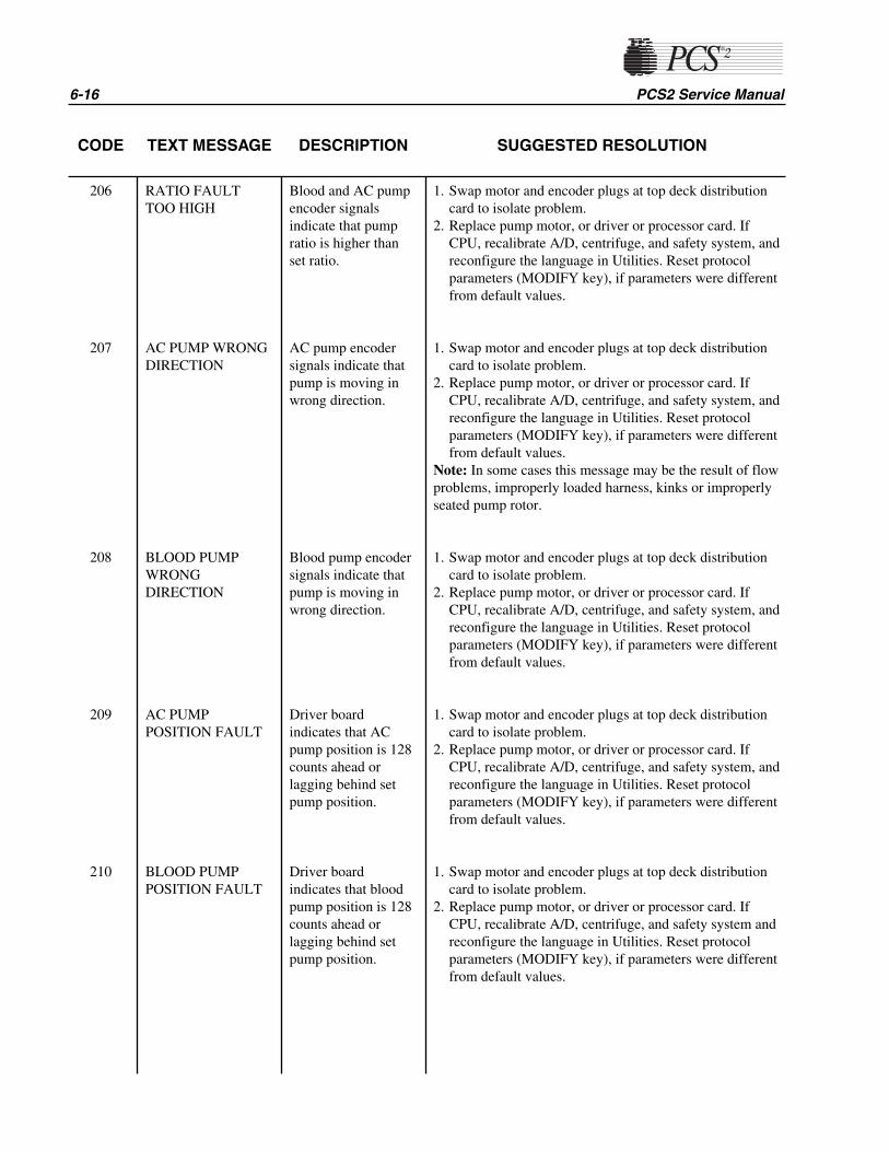
6-16 PCS2 Service Manual
CODE TEXT MESSAGE DESCRIPTION SUGGESTED RESOLUTION
206
207
208
209
210
RATIO FAULTTOO HIGH
AC PUMP WRONGDIRECTION
BLOOD PUMPWRONGDIRECTION
AC PUMPPOSITION FAULT
BLOOD PUMPPOSITION FAULT
Blood and AC pumpencoder signalsindicate that pumpratio is higher thanset ratio.
AC pump encodersignals indicate thatpump is moving inwrong direction.
Blood pump encodersignals indicate thatpump is moving inwrong direction.
Driver boardindicates that ACpump position is 128counts ahead orlagging behind setpump position.
Driver boardindicates that bloodpump position is 128counts ahead orlagging behind setpump position.
1. Swap motor and encoder plugs at top deck distributioncard to isolate problem.
2. Replace pump motor, or driver or processor card. IfCPU, recalibrate A/D, centrifuge, and safety system, andreconfigure the language in Utilities. Reset protocolparameters (MODIFY key), if parameters were differentfrom default values.
1. Swap motor and encoder plugs at top deck distributioncard to isolate problem.
2. Replace pump motor, or driver or processor card. IfCPU, recalibrate A/D, centrifuge, and safety system, andreconfigure the language in Utilities. Reset protocolparameters (MODIFY key), if parameters were differentfrom default values.
Note: In some cases this message may be the result of flowproblems, improperly loaded harness, kinks or improperlyseated pump rotor.
1. Swap motor and encoder plugs at top deck distributioncard to isolate problem.
2. Replace pump motor, or driver or processor card. IfCPU, recalibrate A/D, centrifuge, and safety system, andreconfigure the language in Utilities. Reset protocolparameters (MODIFY key), if parameters were differentfrom default values.
1. Swap motor and encoder plugs at top deck distributioncard to isolate problem.
2. Replace pump motor, or driver or processor card. IfCPU, recalibrate A/D, centrifuge, and safety system andreconfigure the language in Utilities. Reset protocolparameters (MODIFY key), if parameters were differentfrom default values.
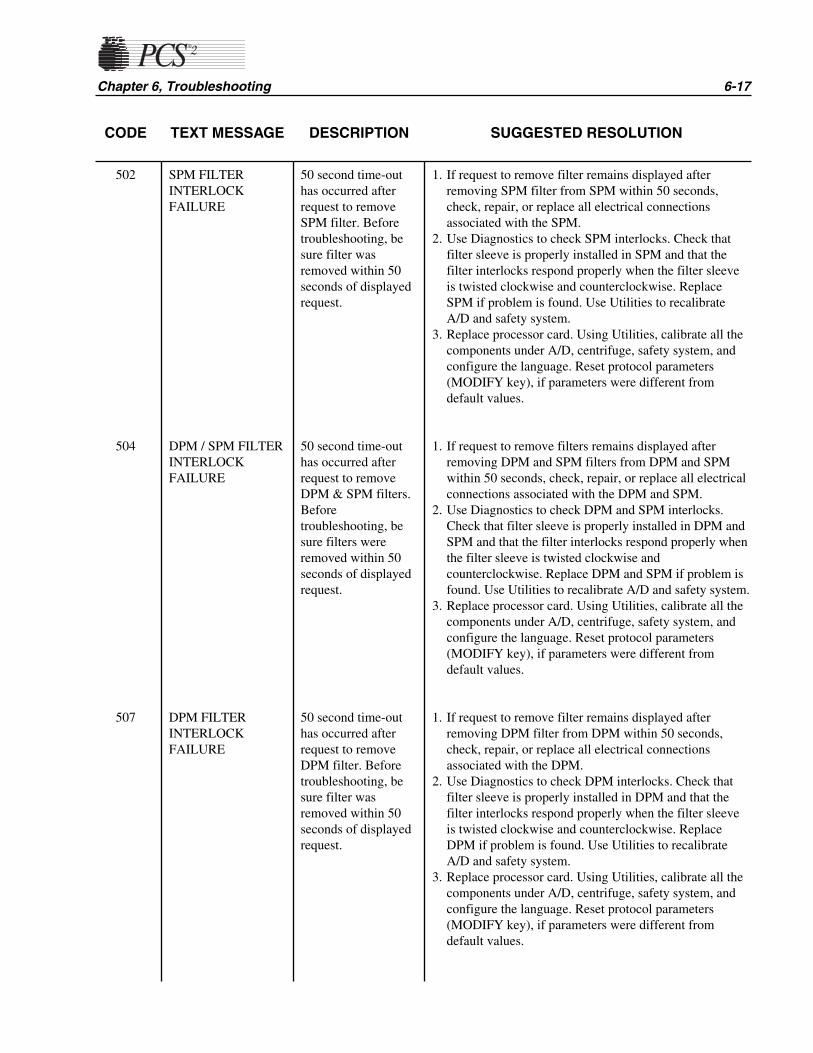
CODE TEXT MESSAGE DESCRIPTION SUGGESTED RESOLUTION
Chapter 6, Troubleshooting 6-17
502
504
507
SPM FILTERINTERLOCKFAILURE
DPM / SPM FILTERINTERLOCKFAILURE
DPM FILTERINTERLOCKFAILURE
50 second time-outhas occurred afterrequest to removeSPM filter. Beforetroubleshooting, besure filter wasremoved within 50seconds of displayedrequest.
50 second time-outhas occurred afterrequest to removeDPM & SPM filters.Beforetroubleshooting, besure filters wereremoved within 50seconds of displayedrequest.
50 second time-outhas occurred afterrequest to removeDPM filter. Beforetroubleshooting, besure filter wasremoved within 50seconds of displayedrequest.
1. If request to remove filter remains displayed afterremoving SPM filter from SPM within 50 seconds,check, repair, or replace all electrical connectionsassociated with the SPM.
2. Use Diagnostics to check SPM interlocks. Check thatfilter sleeve is properly installed in SPM and that thefilter interlocks respond properly when the filter sleeveis twisted clockwise and counterclockwise. ReplaceSPM if problem is found. Use Utilities to recalibrateA/D and safety system.
3. Replace processor card. Using Utilities, calibrate all thecomponents under A/D, centrifuge, safety system, andconfigure the language. Reset protocol parameters(MODIFY key), if parameters were different fromdefault values.
1. If request to remove filters remains displayed afterremoving DPM and SPM filters from DPM and SPMwithin 50 seconds, check, repair, or replace all electricalconnections associated with the DPM and SPM.
2. Use Diagnostics to check DPM and SPM interlocks.Check that filter sleeve is properly installed in DPM andSPM and that the filter interlocks respond properly whenthe filter sleeve is twisted clockwise andcounterclockwise. Replace DPM and SPM if problem isfound. Use Utilities to recalibrate A/D and safety system.
3. Replace processor card. Using Utilities, calibrate all thecomponents under A/D, centrifuge, safety system, andconfigure the language. Reset protocol parameters(MODIFY key), if parameters were different fromdefault values.
1. If request to remove filter remains displayed afterremoving DPM filter from DPM within 50 seconds,check, repair, or replace all electrical connectionsassociated with the DPM.
2. Use Diagnostics to check DPM interlocks. Check thatfilter sleeve is properly installed in DPM and that thefilter interlocks respond properly when the filter sleeveis twisted clockwise and counterclockwise. ReplaceDPM if problem is found. Use Utilities to recalibrateA/D and safety system.
3. Replace processor card. Using Utilities, calibrate all thecomponents under A/D, centrifuge, safety system, andconfigure the language. Reset protocol parameters(MODIFY key), if parameters were different fromdefault values.
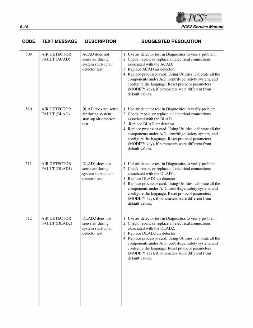
6-18 PCS2 Service Manual
CODE TEXT MESSAGE DESCRIPTION SUGGESTED RESOLUTION
509
510
511
512
AIR DETECTORFAULT (ACAD)
AIR DETECTORFAULT (BLAD)
AIR DETECTORFAULT (DLAD1)
AIR DETECTORFAULT (DLAD2)
ACAD does notsense air duringsystem start-up airdetector test.
BLAD does not senseair during systemstart-up air detectortest.
DLAD1 does notsense air duringsystem start-up airdetector test.
DLAD2 does notsense air duringsystem start-up airdetector test.
1. Use air detector test in Diagnostics to verify problem.2. Check, repair, or replace all electrical connections
associated with the ACAD.3. Replace ACAD air detector.4. Replace processor card. Using Utilities, calibrate all the
components under A/D, centrifuge, safety system, andconfigure the language. Reset protocol parameters(MODIFY key), if parameters were different fromdefault values.
1. Use air detector test in Diagnostics to verify problem.2. Check, repair, or replace all electrical connections
associated with the BLAD.3. Replace BLAD air detector.4. Replace processor card. Using Utilities, calibrate all the
components under A/D, centrifuge, safety system, andconfigure the language. Reset protocol parameters(MODIFY key), if parameters were different fromdefault values.
1. Use air detector test in Diagnostics to verify problem.2. Check, repair, or replace all electrical connections
associated with the DLAD1.3. Replace DLAD1 air detector.4. Replace processor card. Using Utilities, calibrate all the
components under A/D, centrifuge, safety system, andconfigure the language. Reset protocol parameters(MODIFY key), if parameters were different fromdefault values.
1. Use air detector test in Diagnostics to verify problem.2. Check, repair, or replace all electrical connections
associated with the DLAD2.3. Replace DLAD2 air detector.4. Replace processor card. Using Utilities, calibrate all the
components under A/D, centrifuge, safety system, andconfigure the language. Reset protocol parameters(MODIFY key), if parameters were different fromdefault values.
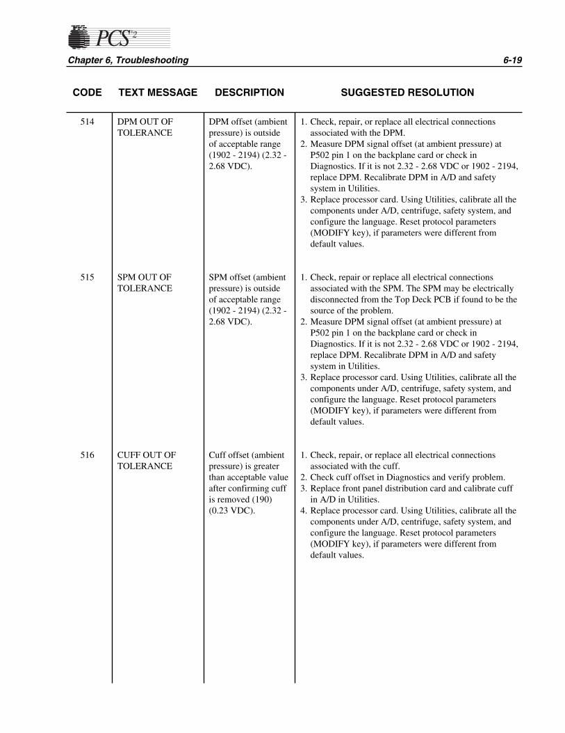
CODE TEXT MESSAGE DESCRIPTION SUGGESTED RESOLUTION
Chapter 6, Troubleshooting 6-19
514
515
516
DPM OUT OFTOLERANCE
SPM OUT OFTOLERANCE
CUFF OUT OFTOLERANCE
DPM offset (ambientpressure) is outsideof acceptable range(1902 - 2194) (2.32 -2.68 VDC).
SPM offset (ambientpressure) is outsideof acceptable range(1902 - 2194) (2.32 -2.68 VDC).
Cuff offset (ambientpressure) is greaterthan acceptable valueafter confirming cuffis removed (190)(0.23 VDC).
1. Check, repair, or replace all electrical connectionsassociated with the DPM.
2. Measure DPM signal offset (at ambient pressure) atP502 pin 1 on the backplane card or check inDiagnostics. If it is not 2.32 - 2.68 VDC or 1902 - 2194,replace DPM. Recalibrate DPM in A/D and safetysystem in Utilities.
3. Replace processor card. Using Utilities, calibrate all thecomponents under A/D, centrifuge, safety system, andconfigure the language. Reset protocol parameters(MODIFY key), if parameters were different fromdefault values.
1. Check, repair or replace all electrical connectionsassociated with the SPM. The SPM may be electricallydisconnected from the Top Deck PCB if found to be thesource of the problem.
2. Measure DPM signal offset (at ambient pressure) atP502 pin 1 on the backplane card or check inDiagnostics. If it is not 2.32 - 2.68 VDC or 1902 - 2194,replace DPM. Recalibrate DPM in A/D and safetysystem in Utilities.
3. Replace processor card. Using Utilities, calibrate all thecomponents under A/D, centrifuge, safety system, andconfigure the language. Reset protocol parameters(MODIFY key), if parameters were different fromdefault values.
1. Check, repair, or replace all electrical connectionsassociated with the cuff.
2. Check cuff offset in Diagnostics and verify problem.3. Replace front panel distribution card and calibrate cuff
in A/D in Utilities.4. Replace processor card. Using Utilities, calibrate all the
components under A/D, centrifuge, safety system, andconfigure the language. Reset protocol parameters(MODIFY key), if parameters were different fromdefault values.

6-20 PCS2 Service Manual
CODE TEXT MESSAGE DESCRIPTION SUGGESTED RESOLUTION
517
701
702
800
WEIGHER OUT OFTOLERANCE
CPU RELAYCLOSINGFAILURE
CPU RELAYOPENINGFAILURE
SOFTWAREWATCHDOGFAULT
****NO FLOW****
Weigher offset isgreater thanacceptable value afterconfirming all weightis removed (175)(0.21 VDC).
CPU relay fails toclose during systemstart-up test.
CPU relay fails toopen during systemstart-up test.
CPU did not executerequired stepsresulting in watchdogtime-out.
Pump set speeds havedecremented to zerodue to low pressuremeasurement byDPM.
1. Check, repair, or replace all electrical connectionsassociated with the weigher.
2. Check weigher offset in Diagnostics and verify theproblem.
3. Replace weigher load cell and calibrate weigher in A/Din Utilities.
4. Replace processor card. Using Utilities, calibrate all thecomponents under A/D, centrifuge, safety system, andconfigure the language. Reset protocol parameters(MODIFY key), if parameters were different fromdefault values.
1. Replace driver card.2. Replace processor card. Using Utilities, calibrate all the
components under A/D, centrifuge, safety system, andconfigure the language. Reset protocol parameters(MODIFY key), if parameters were different fromdefault values.
1. Replace driver card.2. Replace processor card. Using Utilities, calibrate all the
components under A/D, centrifuge, safety system, andconfigure the language. Reset protocol parameters(MODIFY key), if parameters were different fromdefault values.
1. Replace the processor card. Using Utilities, calibrate allthe components under A/D, centrifuge, safety system,and configure the language. Reset protocol parameters(MODIFY key), if parameters were different fromdefault values.
1. This is a normal message if pressure from the donor islow and is possibly caused by a flow restriction.
2. Use Diagnostics to check the DPM calibration.3. Replace DPM. Use Utilities to calibrate DPM and SPM
in A/D screen, and safety system screen for DPM only.
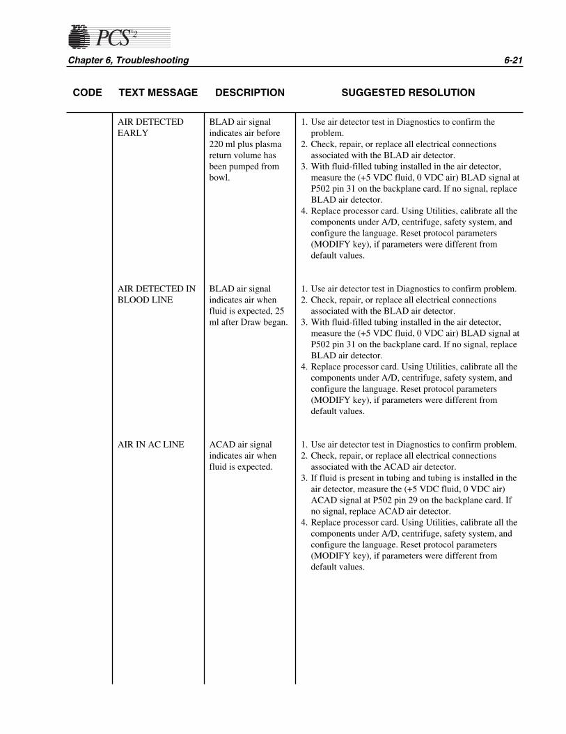
CODE TEXT MESSAGE DESCRIPTION SUGGESTED RESOLUTION
Chapter 6, Troubleshooting 6-21
AIR DETECTEDEARLY
AIR DETECTED INBLOOD LINE
AIR IN AC LINE
BLAD air signalindicates air before220 ml plus plasmareturn volume hasbeen pumped frombowl.
BLAD air signalindicates air whenfluid is expected, 25ml after Draw began.
ACAD air signalindicates air whenfluid is expected.
1. Use air detector test in Diagnostics to confirm theproblem.
2. Check, repair, or replace all electrical connectionsassociated with the BLAD air detector.
3. With fluid-filled tubing installed in the air detector,measure the (+5 VDC fluid, 0 VDC air) BLAD signal atP502 pin 31 on the backplane card. If no signal, replaceBLAD air detector.
4. Replace processor card. Using Utilities, calibrate all thecomponents under A/D, centrifuge, safety system, andconfigure the language. Reset protocol parameters(MODIFY key), if parameters were different fromdefault values.
1. Use air detector test in Diagnostics to confirm problem.2. Check, repair, or replace all electrical connections
associated with the BLAD air detector.3. With fluid-filled tubing installed in the air detector,
measure the (+5 VDC fluid, 0 VDC air) BLAD signal atP502 pin 31 on the backplane card. If no signal, replaceBLAD air detector.
4. Replace processor card. Using Utilities, calibrate all thecomponents under A/D, centrifuge, safety system, andconfigure the language. Reset protocol parameters(MODIFY key), if parameters were different fromdefault values.
1. Use air detector test in Diagnostics to confirm problem.2. Check, repair, or replace all electrical connections
associated with the ACAD air detector.3. If fluid is present in tubing and tubing is installed in the
air detector, measure the (+5 VDC fluid, 0 VDC air)ACAD signal at P502 pin 29 on the backplane card. Ifno signal, replace ACAD air detector.
4. Replace processor card. Using Utilities, calibrate all thecomponents under A/D, centrifuge, safety system, andconfigure the language. Reset protocol parameters(MODIFY key), if parameters were different fromdefault values.

6-22 PCS2 Service Manual
CODE TEXT MESSAGE DESCRIPTION SUGGESTED RESOLUTION
AIR IN DONORLINE 1
AIR IN DONORLINE 2
ARRAY BOUNDSERROR
DLAD 1 air signalindicates air whenfluid is expected.
DLAD 2 air signalindicates air whenfluid is expected.
An internal softwareerror has occurred,where an item wasaccessed beyond adefined array.
1. Use air detector test in Diagnostics to confirm problem.2. Check, repair, or replace all electrical connections
associated with the DLAD1 air detector.3. If fluid is present in tubing and tubing is installed in the
air detector, measure the (+5 VDC fluid, 0 VDC air)DLAD1 signal at P503 pin 2 on the backplane card. If nosignal, replace DLAD1 air detector.
4. Replace processor card. Using Utilities, calibrate all thecomponents under A/D, centrifuge, safety system, andconfigure the language. Reset protocol parameters(MODIFY key), if parameters were different fromdefault values.
1. Use air detector test in Diagnostics to confirm theproblem.
2. Check, repair, or replace all electrical connectionsassociated with the DLAD2 air detector.
3. If fluid is present in tubing and tubing is installed in theair detector, measure the (+5 VDC fluid, 0 VDC air)DLAD2 signal at P503 pin 4 on the backplane card. If nosignal, replace DLAD2 air detector.
4. Replace processor card. Using Utilities, calibrate all thecomponents under A/D, centrifuge, safety system, andconfigure the language. Reset protocol parameters(MODIFY key), if parameters were different fromdefault values.
1. Check +5 VDC power supply.2. Replace processor card. Using Utilities, calibrate all the
components under A/D, centrifuge, safety system, andconfigure the language. Reset protocol parameters(MODIFY key), if parameters were different fromdefault values.
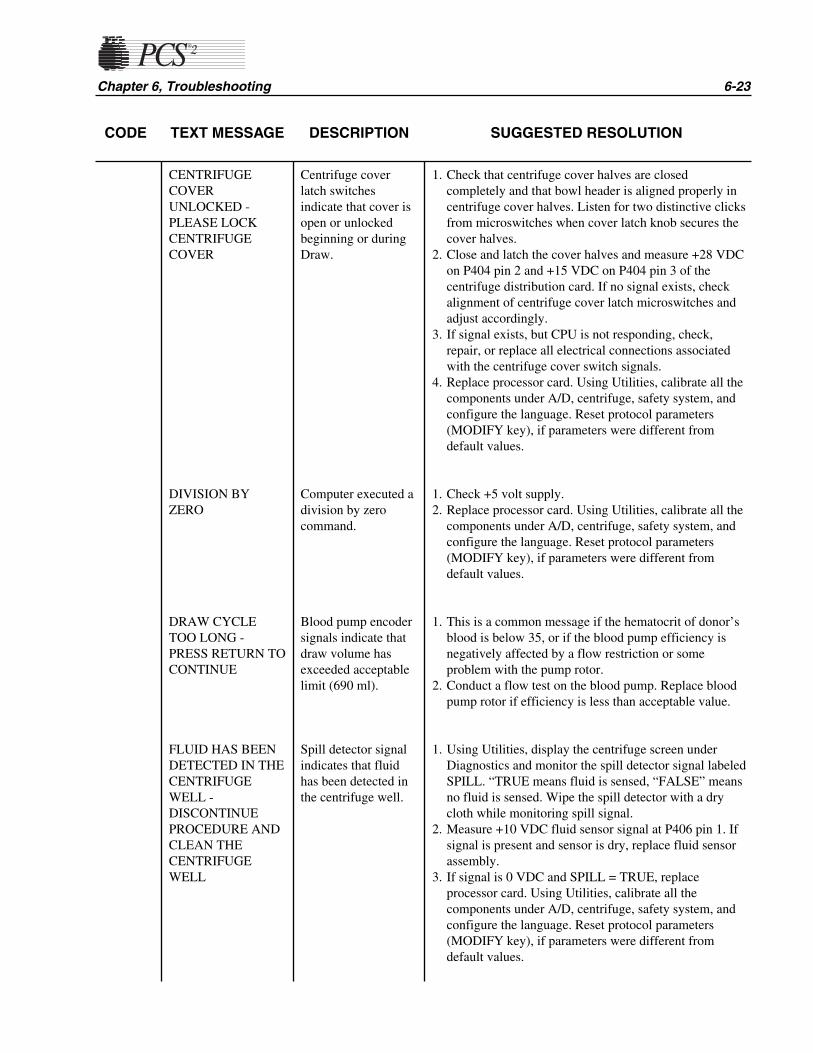
CODE TEXT MESSAGE DESCRIPTION SUGGESTED RESOLUTION
Chapter 6, Troubleshooting 6-23
CENTRIFUGECOVERUNLOCKED -PLEASE LOCKCENTRIFUGECOVER
DIVISION BYZERO
DRAW CYCLETOO LONG -PRESS RETURN TOCONTINUE
FLUID HAS BEENDETECTED IN THECENTRIFUGEWELL -DISCONTINUEPROCEDURE ANDCLEAN THECENTRIFUGEWELL
Centrifuge coverlatch switchesindicate that cover isopen or unlockedbeginning or duringDraw.
Computer executed adivision by zerocommand.
Blood pump encodersignals indicate thatdraw volume hasexceeded acceptablelimit (690 ml).
Spill detector signalindicates that fluidhas been detected inthe centrifuge well.
1. Check that centrifuge cover halves are closedcompletely and that bowl header is aligned properly incentrifuge cover halves. Listen for two distinctive clicksfrom microswitches when cover latch knob secures thecover halves.
2. Close and latch the cover halves and measure +28 VDCon P404 pin 2 and +15 VDC on P404 pin 3 of thecentrifuge distribution card. If no signal exists, checkalignment of centrifuge cover latch microswitches andadjust accordingly.
3. If signal exists, but CPU is not responding, check,repair, or replace all electrical connections associatedwith the centrifuge cover switch signals.
4. Replace processor card. Using Utilities, calibrate all thecomponents under A/D, centrifuge, safety system, andconfigure the language. Reset protocol parameters(MODIFY key), if parameters were different fromdefault values.
1. Check +5 volt supply.2. Replace processor card. Using Utilities, calibrate all the
components under A/D, centrifuge, safety system, andconfigure the language. Reset protocol parameters(MODIFY key), if parameters were different fromdefault values.
1. This is a common message if the hematocrit of donor’sblood is below 35, or if the blood pump efficiency isnegatively affected by a flow restriction or someproblem with the pump rotor.
2. Conduct a flow test on the blood pump. Replace bloodpump rotor if efficiency is less than acceptable value.
1. Using Utilities, display the centrifuge screen underDiagnostics and monitor the spill detector signal labeledSPILL. “TRUE means fluid is sensed, “FALSE” meansno fluid is sensed. Wipe the spill detector with a drycloth while monitoring spill signal.
2. Measure +10 VDC fluid sensor signal at P406 pin 1. Ifsignal is present and sensor is dry, replace fluid sensorassembly.
3. If signal is 0 VDC and SPILL = TRUE, replaceprocessor card. Using Utilities, calibrate all thecomponents under A/D, centrifuge, safety system, andconfigure the language. Reset protocol parameters(MODIFY key), if parameters were different fromdefault values.

6-24 PCS2 Service Manual
CODE TEXT MESSAGE DESCRIPTION SUGGESTED RESOLUTION
HIGH PRESSUREIN DONOR LINE -RELIEVE PRESS.BEFOREPHLEBOTOMY
ILLEGAL OPCODEERROR
NEGATIVE RTNPRESSURE
OVERFLOWERROR
RETURN CYCLETOO LONG
DPM pressuremeasurement exceedsacceptable limit inReady mode (>100mmHg).
Computer executedan illegal instruction.Computer is lost andcannot executecommands.
DPM pressuremeasurement exceedsacceptable limit (<-40).
An internalcomputational errorhas occurred.
BLAD air signalindicates fluid, afterbowl volume plusplasma return volumehas been pumpedfrom bowl.
1. Check calibration of DPM in Diagnostics.
1. Check +5 volt supply.2. Replace processor card. Using Utilities, calibrate all the
components under A/D, centrifuge, safety system, andconfigure the language. Reset protocol parameters(MODIFY key), if parameters were different fromdefault values.
1. This is a highly unusual message which may indicate anintermittently defective DPM or A/D circuit. Checkcalibration of DPM in Utilities.
2. Replace DPM and calibrate A/D and safety system inUtilities.
3. Replace the processor card. Using Utilities, calibrate allthe components under A/D, centrifuge, safety system,and configure the language. Reset protocol parameters(MODIFY key), if parameters were different fromdefault values.
1. Check +5 VDC power supply voltage.2. Replace the processor card. Using Utilities, calibrate all
the components under A/D, centrifuge,safety system, andconfigure the language. Reset protocol parameters(MODIFY key) if parameters were different from defaultvalues.
1. If fluid still exists in the tubing and especially the bowl,check for obstructions in the blood pump tubing oreffluent line, or for air in wrong bag. If no obstructionsexist, check the efficiency of the blood pump. Replaceblood pump rotor if efficiency is less than acceptablevalue.
2. If no fluid exists in the tubing, the air detector did notsense air. Replace the air detector.

CODE TEXT MESSAGE DESCRIPTION SUGGESTED RESOLUTION
Chapter 6, Troubleshooting 6-25
SOFTWAREWATCHDOGFAULT - CURRENTMODULE ID=XEXPECTEDMODULE ID=XCURRENTSTATE=X
SOFTWAREWATCHDOGFAULT - INVALIDSTATE=X
SPM / DPM FILTERIS NOTINSTALLED -PLEASE INSTALLAND UNCLAMP IT
SPM FILTER ISNOT INSTALLED -PLEASE INSTALLAND UNCLAMP IT
THE PROTOCOLPARAMETERSHAVE RESET TOTHEIR ORIGINALVALUES
CPU did not executerequired stepsresulting in watchdogtime-out.
CPU did not executerequired stepsresulting in watchdogtime-out.
DPM and SPMinterlock signalsindicate that DPMand SPM filters arenot installed anytimeafter systeminitialization.
SPM interlocksignals indicate thatSPM filter is notinstalled during Drawor Return.
Protocol parameterCRC does not matchvalue stored inNVRAM.
1. Replace the processor card. Using Utilities, calibrate allthe components under A/D, centrifuge, safety system,and configure the language. Reset protocol parameters(MODIFY key), if parameters were different fromdefault values.
1. Replace the processor card. Recalibrate A/D, centrifugeand safety system, and reconfigure the language inUtilities. Reset protocol parameters (MODIFY key), ifparameters were different from default values.
1. Verify that white sleeves are fully seated.2. Check, repair, or replace all electrical connections
associated with the DPM and SPM.3. Replace DPM and SPM. Use Utilities to calibrate DPM
and SPM in A/D screen, and safety system screen forDPM only.
4. Replace the processor card. Using Utilities, calibrate allthe components under A/D, centrifuge, safety system,and configure the language. Reset protocol parameters(MODIFY key), if parameters were different fromdefault values.
1. Verify that white sleeves are fully seated.2. Check, repair, or replace all electrical connections
associated with the SPM.3. Replace SPM. Use Utilities to calibrate SPM in the A/D
screen.4. Replace the processor card. Using Utilities, calibrate all
the components under A/D, centrifuge, safety system,and configure the language. Reset protocol parameters(MODIFY key), if parameters were different fromdefault values.
1. Normally displayed the first power-up after a programchip has been changed. If message is reoccurring,replace processor card. Using Utilities, calibrate all thecomponents under A/D, centrifuge, safety system, andconfigure the language. Reset protocol parameters(MODIFY key), if parameters were different fromdefault values.
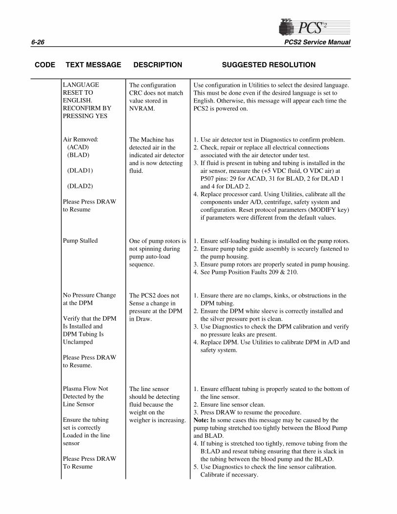
6-26 PCS2 Service Manual
CODE TEXT MESSAGE DESCRIPTION SUGGESTED RESOLUTION
LANGUAGERESET TOENGLISH.RECONFIRM BYPRESSING YES
Air Removed:(ACAD)(BLAD)
(DLAD1)
(DLAD2)
Please Press DRAWto Resume
Pump Stalled
No Pressure Changeat the DPM
Verify that the DPMIs Installed andDPM Tubing IsUnclamped
Please Press DRAWto Resume.
Plasma Flow NotDetected by theLine Sensor
Ensure the tubingset is correctlyLoaded in the linesensor
Please Press DRAWTo Resume
The configurationCRC does not matchvalue stored inNVRAM.
The Machine hasdetected air in theindicated air detectorand is now detectingfluid.
One of pump rotors isnot spinning duringpump auto-loadsequence.
The PCS2 does notSense a change inpressure at the DPMin Draw.
The line sensorshould be detectingfluid because theweight on theweigher is increasing.
Use configuration in Utilities to select the desired language.This must be done even if the desired language is set toEnglish. Otherwise, this message will appear each time thePCS2 is powered on.
1. Use air detector test in Diagnostics to confirm problem.2. Check, repair or replace all electrical connections
associated with the air detector under test.3. If fluid is present in tubing and tubing is installed in the
air sensor, measure the (+5 VDC fluid, O VDC air) atP507 pins: 29 for ACAD, 31 for BLAD, 2 for DLAD 1and 4 for DLAD 2.
4. Replace processor card. Using Utilities, calibrate all thecomponents under A/D, centrifuge, safety system andconfiguration. Reset protocol parameters (MODIFY key)if parameters were different from the default values.
1. Ensure self-loading bushing is installed on the pump rotors.2. Ensure pump tube guide assembly is securely fastened to
the pump housing.3. Ensure pump rotors are properly seated in pump housing.4. See Pump Position Faults 209 & 210.
1. Ensure there are no clamps, kinks, or obstructions in theDPM tubing.
2. Ensure the DPM white sleeve is correctly installed andthe silver pressure port is clean.
3. Use Diagnostics to check the DPM calibration and verifyno pressure leaks are present.
4. Replace DPM. Use Utilities to calibrate DPM in A/D andsafety system.
1. Ensure effluent tubing is properly seated to the bottom ofthe line sensor.
2. Ensure line sensor clean.3. Press DRAW to resume the procedure.Note: In some cases this message may be caused by thepump tubing stretched too tightly between the Blood Pumpand BLAD.4. If tubing is stretched too tightly, remove tubing from the
B:LAD and reseat tubing ensuring that there is slack inthe tubing between the blood pump and the BLAD.
5. Use Diagnostics to check the line sensor calibration.Calibrate if necessary.

Chapter 6, Troubleshooting 6-27
CODE TEXT MESSAGE DESCRIPTION SUGGESTED RESOLUTION
Weight is notsynchronized withthe volumeprocessed.
Please Ensure theFollowing:*Disp. set is properlyinstalled* Tubing is notclamped or blocked
Please Press DRAWto Resume
Possible Red CellSpill
High Pressure ReturnPlease check forocclusions:*Venipuncture*Donor Line
The machines doesnot sense thecollection weight isincreasing asexpected.
The line sensor hasdetected a drop involtage that isunexpected.
DPM pressuremeasurement isgreater than 260mmHg.
1. Ensure the machine is configured for the correctprotocol.
2. Ensure blood pump rotor is properly installed in pumphousing and all pump rollers spin freely.
3. Using Diagnostics, verify weigher calibration is 1000g+/-5. Recalibrate using A/D, if necessary.
4. Ensure collection container is properly placed on theweigher arm.
5. Ensure collection container is not touching side ofmachine.
1. There are certain procedural or donor related variablesthat can influence red cell spills. These variables includesevere flow problems, incorrect draw speeds, initiatingDraw with blood remaining in the bowl, dirty bowloptics/line sensor, placement of the machine in directsunlight or donor conditions such as lipemic plasma.
2. Use Utilities to display the optics and line sensor digitalvoltages in Diagnostics under Transducers.
3. Using the Optics Test Fixture ETD-5060, ensure theoptic aiming is centered on the fixture aiming dot. SeeBowl Optics Signal in Chapter 4, Calibration.
4. Clean optics lens. Ensure the Optics Gray Card voltageis between 2295-3278 (2.8 -4.0v) and the Optics Offset(open value) is between 1-82 (0 +/- 0.10v). Calibrate ifnecessary; see Bowl Optics Signal in Chapter 4,Calibration.
5. If the Optics Offset and Gray voltages are unable to becalibrated, replace the photoelectric assembly.
6. Clean the line sensor. Ensure the line sensor voltage isbetween 2866-3276 (3.75 +/- 0.25 VDC) and blackvoltage is between 0 and 103. Calibrate if necessaryusing the trim pot located inside the line sensor. If theline sensor cannot be calibrated, replace the line sensor.
1. This message appears if major flow problems occur inReturn as a result of an obstruction in the disposabletubing or vein infiltration at the needle site.
2. When pressure returns to normal limits, the followingmessage will appear:
PRESSURE IS RELIEVED.
3. Press PRIME to continue.4. Check calibration of DPM in Diagnostics. Recalibrate
the DPM if necessary. See DPM under A/D in Chapter4, Calibration.
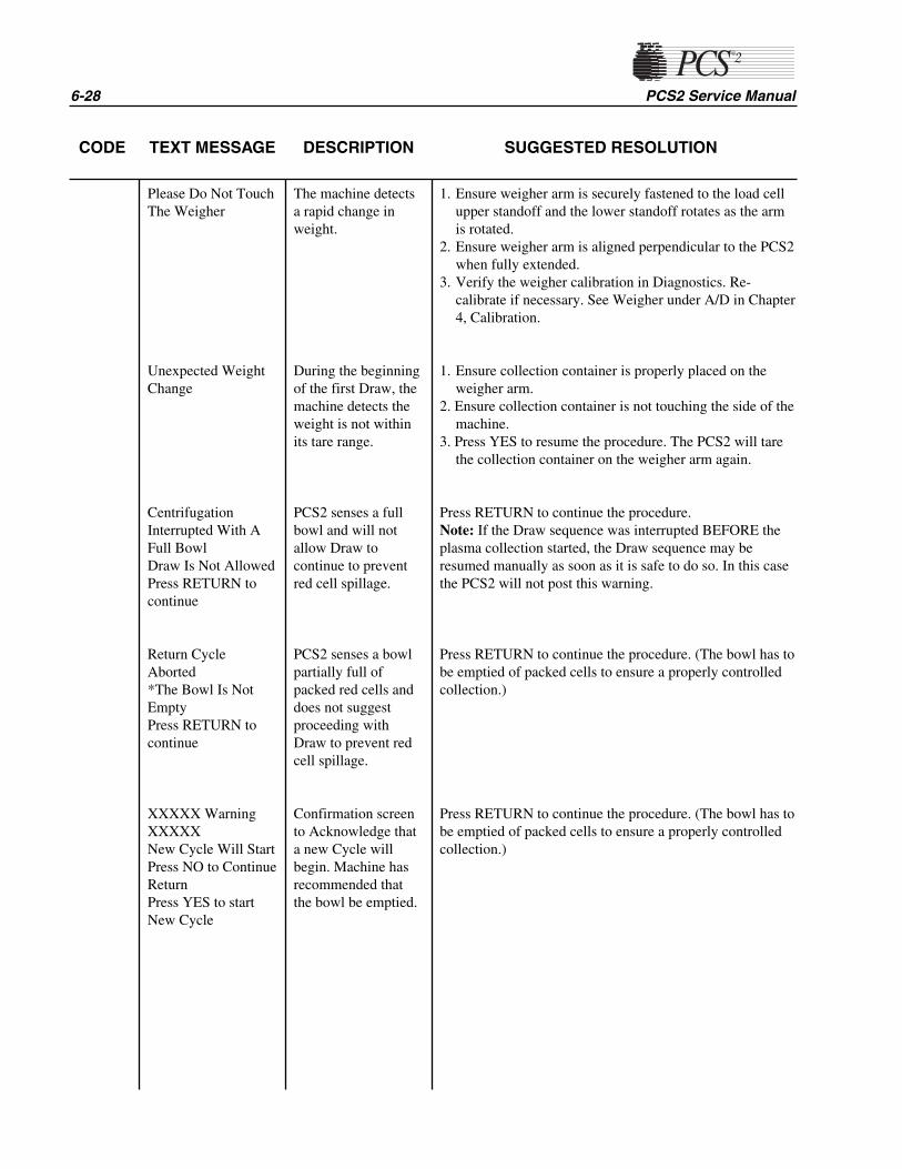
6-28 PCS2 Service Manual
CODE TEXT MESSAGE DESCRIPTION SUGGESTED RESOLUTION
Please Do Not TouchThe Weigher
Unexpected WeightChange
CentrifugationInterrupted With AFull BowlDraw Is Not AllowedPress RETURN tocontinue
Return CycleAborted*The Bowl Is NotEmptyPress RETURN tocontinue
XXXXX WarningXXXXXNew Cycle Will StartPress NO to ContinueReturnPress YES to startNew Cycle
The machine detectsa rapid change inweight.
During the beginningof the first Draw, themachine detects theweight is not withinits tare range.
PCS2 senses a fullbowl and will notallow Draw tocontinue to preventred cell spillage.
PCS2 senses a bowlpartially full ofpacked red cells anddoes not suggestproceeding withDraw to prevent redcell spillage.
Confirmation screento Acknowledge thata new Cycle willbegin. Machine hasrecommended thatthe bowl be emptied.
1. Ensure weigher arm is securely fastened to the load cellupper standoff and the lower standoff rotates as the armis rotated.
2. Ensure weigher arm is aligned perpendicular to the PCS2when fully extended.
3. Verify the weigher calibration in Diagnostics. Re-calibrate if necessary. See Weigher under A/D in Chapter4, Calibration.
1. Ensure collection container is properly placed on theweigher arm.
2. Ensure collection container is not touching the side of themachine.
3. Press YES to resume the procedure. The PCS2 will tarethe collection container on the weigher arm again.
Press RETURN to continue the procedure.Note: If the Draw sequence was interrupted BEFORE theplasma collection started, the Draw sequence may beresumed manually as soon as it is safe to do so. In this casethe PCS2 will not post this warning.
Press RETURN to continue the procedure. (The bowl has tobe emptied of packed cells to ensure a properly controlledcollection.)
Press RETURN to continue the procedure. (The bowl has tobe emptied of packed cells to ensure a properly controlledcollection.)
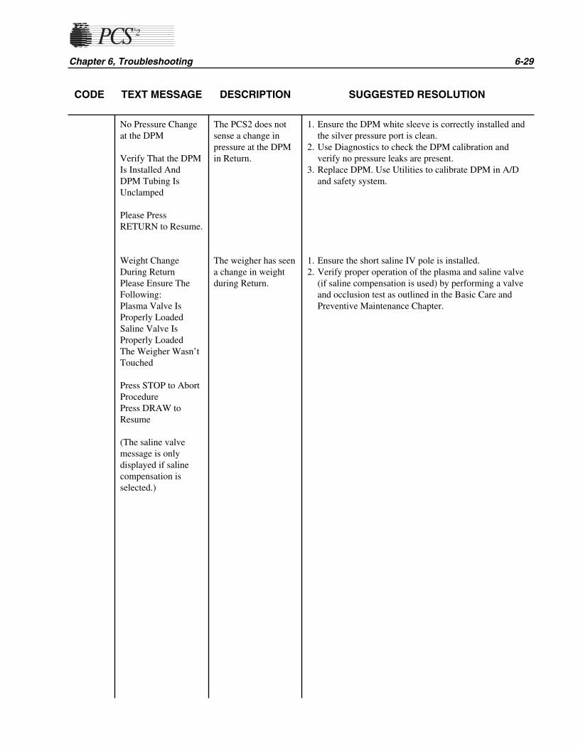
Chapter 6, Troubleshooting 6-29
CODE TEXT MESSAGE DESCRIPTION SUGGESTED RESOLUTION
No Pressure Changeat the DPM
Verify That the DPMIs Installed AndDPM Tubing IsUnclamped
Please PressRETURN to Resume.
Weight ChangeDuring ReturnPlease Ensure TheFollowing:Plasma Valve IsProperly LoadedSaline Valve IsProperly LoadedThe Weigher Wasn’tTouched
Press STOP to AbortProcedurePress DRAW toResume
(The saline valvemessage is onlydisplayed if salinecompensation isselected.)
The PCS2 does notsense a change inpressure at the DPMin Return.
The weigher has seena change in weightduring Return.
1. Ensure the DPM white sleeve is correctly installed andthe silver pressure port is clean.
2. Use Diagnostics to check the DPM calibration andverify no pressure leaks are present.
3. Replace DPM. Use Utilities to calibrate DPM in A/Dand safety system.
1. Ensure the short saline IV pole is installed.2. Verify proper operation of the plasma and saline valve
(if saline compensation is used) by performing a valveand occlusion test as outlined in the Basic Care andPreventive Maintenance Chapter.
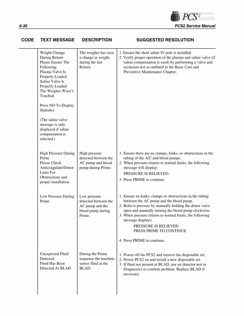
6-30 PCS2 Service Manual
CODE TEXT MESSAGE DESCRIPTION SUGGESTED RESOLUTION
Weight ChangeDuring ReturnPlease Ensure TheFollowing:Plasma Valve IsProperly LoadedSaline Valve IsProperly LoadedThe Weigher Wasn’tTouched
Press NO To DisplayStatistics
(The saline valvemessage is onlydisplayed if salinecompensation isselected.)
High Pressure DuringPrimePlease CheckAnticoagulant/DonorLines ForObstructions andproper installation.
Low Pressure DuringPrime
Unexpected FluidDetected Fluid Has BeenDetected At BLAD
The weigher has seena change in weightduring the lastReturn.
High pressuredetected between theAC pump and bloodpump during Prime.
Low pressuredetected between theAC pump and theblood pump duringPrime.
During the Primesequence the machinesenses fluid at theBLAD.
1. Ensure the short saline IV pole is installed.2. Verify proper operation of the plasma and saline valve (if
saline compensation is used) by performing a valve andocclusion test as outlined in the Basic Care andPreventive Maintenance Chapter.
1. Ensure there are no clamps, kinks, or obstructions in thetubing of the A/C and blood pumps.
2. When pressure returns to normal limits, the followingmessage will display:
PRESSURE IS RELIEVED.
3. Press PRIME to continue.
1. Ensure no kinks, clamps or obstructions in the tubingbetween the AC pump and the blood pump.
2. Relieve pressure by manually holding the donor valveopen and manually turning the blood pump clockwise.
3. When pressure returns to normal limits, the followingmessage displays:
PRESSURE IS RELIEVEDPRESS PRIME TO CONTINUE
4. Press PRIME to continue.
1. Power off the PCS2 and remove the disposable set.2. Power PCS2 on and install a new disposable set.3. If fluid not present at BLAD, use air detector test in
Diagnostics to confirm problem. Replace BLAD ifnecessary.

Chapter 6, Troubleshooting 6-31
CODE TEXT MESSAGE DESCRIPTION SUGGESTED RESOLUTION
Air In Donor Line 2Press Prime ToContinue
Fluid not seen byDLAD2 after 40 mlof anticoagulantpumped.
1. Ensure proper placement of tubing in DLAD2.2. Ensure no kinks or twists in tubing from ACAD to
DLAD2.3. Ensure DLAD2 is clean.4. Press PRIME to continue.5. If fluid is present at DLAD2, use air detector test in
Diagnostics to confirm problem. Replace DLAD2 ifnecessary.
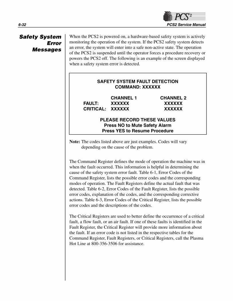
6-32 PCS2 Service Manual
When the PCS2 is powered on, a hardware-based safety system is activelymonitoring the operation of the system. If the PCS2 safety system detectsan error, the system will enter into a safe non-active state. The operationof the PCS2 is suspended until the operator forces a procedure recovery orpowers the PCS2 off. The following is an example of the screen displayedwhen a safety system error is detected.
Note: The codes listed above are just examples. Codes will varydepending on the cause of the problem.
The Command Register defines the mode of operation the machine was inwhen the fault occurred. This information is helpful in determining thecause of the safety system error fault. Table 6-1, Error Codes of theCommand Register, lists the possible error codes and the correspondingmodes of operation. The Fault Registers define the actual fault that wasdetected. Table 6-2, Error Codes of the Fault Register, lists the possibleerror codes, explanation of the codes, and the corresponding correctiveactions. Table 6-3, Error Codes of the Critical Register, lists the possibleerror codes and the descriptions of the codes.
The Critical Registers are used to better define the occurrence of a criticalfault, a flow fault, or an air fault. If one of these faults is identified in theFault Register, the Critical Register will provide more information aboutthe fault. If an error code is not listed in the respective tables for theCommand Register, Fault Registers, or Critical Registers, call the PlasmaHot Line at 800-356-3506 for assistance.
Safety SystemError
Messages
SAFETY SYSTEM FAULT DETECTIONCOMMAND: XXXXXX
CHANNEL 1 CHANNEL 2FAULT: XXXXXX XXXXXXCRITICAL: XXXXXX XXXXXX
PLEASE RECORD THESE VALUESPress NO to Mute Safety Alarm
Press YES to Resume Procedure
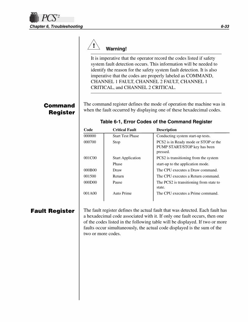
Chapter 6, Troubleshooting 6-33
Warning!
It is imperative that the operator record the codes listed if safetysystem fault detection occurs. This information will be needed toidentify the reason for the safety system fault detection. It is alsoimperative that the codes are properly labeled as COMMAND,CHANNEL 1 FAULT, CHANNEL 2 FAULT, CHANNEL 1CRITICAL, and CHANNEL 2 CRITICAL.
The command register defines the mode of operation the machine was inwhen the fault occurred by displaying one of these hexadecimal codes.
Table 6-1, Error Codes of the Command Register
Code Critical Fault Description
000000 Start Test Phase Conducting system start-up tests.
000700 Stop PCS2 is in Ready mode or STOP or thePUMP START/STOP key has been pressed.
001C00 Start Application PCS2 is transitioning from the system
Phase start-up to the application mode.
000B00 Draw The CPU executes a Draw command.
001500 Return The CPU executes a Return command.
000D00 Pause The PCS2 is transitioning from state to state.
001A00 Auto Prime The CPU executes a Prime command.
The fault register defines the actual fault that was detected. Each fault hasa hexadecimal code associated with it. If only one fault occurs, then oneof the codes listed in the following table will be displayed. If two or morefaults occur simultaneously, the actual code displayed is the sum of thetwo or more codes.
!
CommandRegister
Fault Register
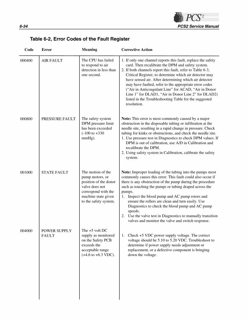
1. If only one channel reports this fault, replace the safetycard. Then recalibrate the DPM and safety system.
2. If both channels report this fault, refer to Table 6-3,Critical Register, to determine which air detector mayhave sensed air. After determining which air detectormay have faulted, refer to the appropriate error codes(“Air in Anticoagulant Line” for ACAD, “Air in DonorLine 1” for DLAD1, “Air in Donor Line 2” for DLAD2)listed in the Troubleshooting Table for the suggestedresolution.
Note: This error is most commonly caused by a majorobstruction in the disposable tubing or infiltration at theneedle site, resulting in a rapid change in pressure. Checktubing for kinks or obstructions, and check the needle site.1. Use pressure test in Diagnostics to check DPM values. If
DPM is out of calibration, use A/D in Calibration andrecalibrate the DPM.
2. Using safety system in Calibration, calibrate the safetysystem.
Note: Improper loading of the tubing into the pumps mostcommonly causes this error. This fault could also occur ifthere is any obstruction of the pump during the proceduresuch as touching the pumps or tubing draped across thepumps.1. Inspect the blood pump and AC pump rotors and
ensure the rollers are clean and turn easily. UseDiagnostics to check the blood pump and AC pumpspeeds.
2. Use the valve test in Diagnostics to manually transitionvalves and monitor the valve and switch response.
1. Check +5 VDC power supply voltage. The correctvoltage should be 5.10 to 5.20 VDC. Troubleshoot todetermine if power supply needs adjustment orreplacement, or a defective component is bringingdown the voltage.
6-34 PCS2 Service Manual
Code Error Meaning Corrective Action
000400
000800
001000
004000
AIR FAULT
PRESSURE FAULT
STATE FAULT
POWER SUPPLYFAULT
The CPU has failedto respond to airdetection in less thanone second.
The safety systemDPM pressure limithas been exceeded (-100 to +330mmHg).
The motion of thepump motors, orposition of the donorvalve does notcorrespond with themachine state givento the safety system.
The +5 volt DCsupply as monitoredon the Safety PCBexceeds theacceptable range(+4.6 to +6.3 VDC).
Table 6-2, Error Codes of the Fault Register

Chapter 6, Troubleshooting 6-35
The critical register is used to better define the occurrence of a criticalfault, flow fault or air fault. If one of these faults is identified in the faultregister, then the critical register will provide more information about thefault. Each fault has a hexadecimal code associated with it. If one faultoccurs, one of the codes listed below will be displayed. If two or morefaults occur simultaneously, the actual code displayed will be the sum oftwo or more codes. This scenario is likely, because an air detector codewill be summed with the fault code if the air detector is sensing air at thetime the fault is detected.
Table 6-3, Error Codes of the Critical Register
Code Critical Fault Description
000100 Motor Movement Fault The motor has moved during the system start-up test phase.
000200 Auto Prime Fault An auto prime command has been received from the CPU after an application state has been entered.
000400 Interlock Fault The CPU has failed to respond to an open DPM interlock within one second.
000800 Ratio Fault The pump ratio exceeds the acceptable range.
001000 ACAD Status ACAD was sensing air when fault occurred.
002000 DLAD1 Status DLAD1 was sensing air when fault occurred.
004000 DLAD2 Status DLAD2 was sensing air when fault occurred.
CriticalRegister
This chapter is a reference for identifying the repair parts available for thePCS2. All available parts are listed on pages 7-8 to 7-11, while many ofthe parts are identified on pages 7-3 to 7-7 by callouts from illustrations.
To place an order, please call the Haemonetics Hot Line at 800-356-3506.
Chapter 7Repair Parts List
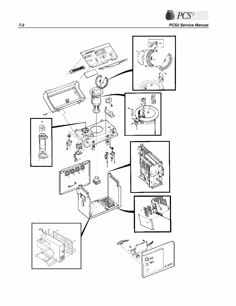
7-2 PCS2 Service Manual

Chapter 7, Repair Parts List 7-3
37108-00Membrane Panel
47242-00Top CoverDecorativePanel Assy.
36387-00Vacuum Display
36931-00Top CoverAssy. 36917-00
Centrifuge Assy.
35218-00Control PanelDistribution Card
49730-00Line Sensor
52025-00Weigher Arm
35159-02Blood LineAir Detector
39269-00Weigher Load Cell
36930-00Pinch ValveAssy.
36913-00IV Pole MountAssy.
37030-00Rear PanelAssy.
35830-00Fan Assy.
37049-00SPM/DPMAssy.
37107-00Membrane PanelAssy.
35159-01AC AirDetector
11383-05 AirDetectorGrommet
35466-00Pinch ValveGrommet
36935-00Front PanelAssy.
35226-00Front PanelDistributionCable
35209-00Front PanelDistribution Card
35450-00CompressorAssy.
17541-02Filter Guide
35159-01Donor Line AirDetector #1
35159-02Donor Line AirDetector #2
(LN 06002-110-NAdo not have SPM)
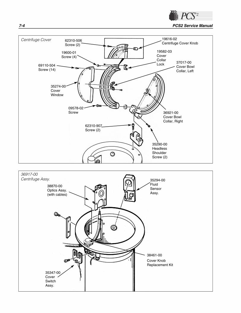
7-4 PCS2 Service Manual
62310-506Screw (2)
19600-01Screw (4)
69110-504Screw (14)
35274-00CoverWindow
62310-907Screw (2)
19582-03CoverCollarLock 37017-00
Cover BowlCollar, Left
36921-00Cover BowlCollar, Right
35290-00HeadlessShoulderScrew (2)
Centrifuge Cover
35294-00FluidSensorAssy.
36917-00Centrifuge Assy.
35347-00CoverSwitchAssy.
38870-00Optics Assy.(with cables)
38461-00
Cover KnobReplacement Kit
19616-02Centrifuge Cover Knob
09578-02Screw

Chapter 7, Repair Parts List 7-5
37009-00CPU Card
35203-00Safety Card
35200-00DriverCard
37010-00Card Cage
35206-00BackplaneCard
35215-00CentrifugeDistributionCard
17548-00Air Filter -Large
61620-904Screw
18138-00Air Filter -Small
35634-00Drain TubeAssy.

7-6 PCS2 Service Manual
37121-00Todd Power Supply Assembly
18878-00Power Supply(Todd)
36823-00CentrifugeDriver Card
35192-00OpticsPhotoelectricAssy.
48630-00Condor Power Supply Assembly
35358-00Power Entry Module Assembly
35358-00Power EntryModule Assembly
19296-01Fuse
48102-00Power Supply(Condor)
36823-00CentrifugeDriver Card
35192-00OpticsPhotoelectricAssy.
If replacing a Todd Power Supply with aCondor Power Supply, order P/N 48895-00Condor Power Supply (Field Replacement).

Chapter 7, Repair Parts List 7-7
36928-00AC Pump Assy.
36926-00Blood Pump Assy.
38671-00Pump RotorAssy.
38536-00 Self LoadingBushing
37035-00PumpGasket
35367-00Pump MotorAssy.
38071-02Pump TubeGuide
62311-408Screw
37040-00 Label, Blood Pump
37041-00 Label, AC Pump
37034-02PumpHousing
61210-908
Screw

7-8 PCS2 Service Manual
Parts Description Part No. Returnable
Cabinet Final Assembly 36922-00Top Deck Distribution Power Cable..................................................35227-00Top Deck Distribution Signal Cable..................................................35228-00Front Panel Distribution Cable..........................................................35226-00Drain Bag .........................................................................................35643-00IV Pole Assembly (AC) .....................................................................36895-02Saline Pole Assembly .......................................................................47955-02Power Cord Assembly......................................................................19417-00
Top Cover Assembly 36931-00....................XTop Cover .........................................................................................34891-03....................XMembrane Panel Assembly .............................................................37107-00....................X
Membrane Panel ........................................................................37108-00Vacuum Display .........................................................................36387-00Control Panel Distribution Card..................................................35218-00....................XDisplay Power Cable..................................................................35233-00Display Signal Cable..................................................................35232-00
Control Distribution Cable Upgrade Kit 49320-00Control Panel Distribution Cable ......................................................35231-00Top Cover Decorative Panel Assembly ............................................47242-00
Decorative Panel ........................................................................35125-02Retainer Pad...............................................................................13549-02
Centrifuge Assembly (complete) 36917-00....................XCentrifuge Assembly (w/o optics) ....................................................36919-00....................X
O-ring .........................................................................................37027-01Drain Tube..................................................................................06299-06
Fluid Sensor Assembly.....................................................................35294-00Optics Assembly (includes both block and cable) ..........................38870-00....................XCover Switch Assembly....................................................................35347-00Cap/Cover Assembly .......................................................................36920-00
Headless Shoulder Screw on Cover Hinge................................35290-00Shoulder Screw, Socket Head ...................................................09578-02
Nylon Washer .......................................................................14269-07Screw, Socket Head Cap .....................................................19600-02
Screw, Socket Head (Base Hinge).............................................62310-907Cover Window............................................................................35274-00Screw, Button Head Socket .......................................................69110-504
Centrifuge Knob Replacement Kit .......................................38461-00Cover Latch Knob Disk ........................................................36859-02
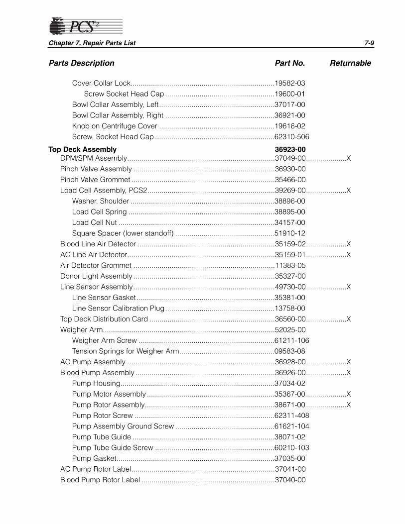
Chapter 7, Repair Parts List 7-9
Parts Description Part No. Returnable
Cover Collar Lock.......................................................................19582-03Screw Socket Head Cap......................................................19600-01
Bowl Collar Assembly, Left.........................................................37017-00Bowl Collar Assembly, Right ......................................................36921-00Knob on Centrifuge Cover .........................................................19616-02Screw, Socket Head Cap ...........................................................62310-506
Top Deck Assembly 36923-00DPM/SPM Assembly.........................................................................37049-00....................XPinch Valve Assembly ......................................................................36930-00Pinch Valve Grommet .......................................................................35466-00Load Cell Assembly, PCS2...............................................................39269-00....................X
Washer, Shoulder .......................................................................38896-00Load Cell Spring ........................................................................38895-00Load Cell Nut .............................................................................34157-00Square Spacer (lower standoff) .................................................51910-12
Blood Line Air Detector ....................................................................35159-02....................XAC Line Air Detector.........................................................................35159-01....................XAir Detector Grommet ......................................................................11383-05Donor Light Assembly ......................................................................35327-00Line Sensor Assembly......................................................................49730-00....................X
Line Sensor Gasket ....................................................................35381-00Line Sensor Calibration Plug......................................................13758-00
Top Deck Distribution Card ..............................................................36560-00....................XWeigher Arm.....................................................................................52025-00
Weigher Arm Screw ...................................................................61211-106Tension Springs for Weigher Arm...............................................09583-08
AC Pump Assembly .........................................................................36928-00....................XBlood Pump Assembly .....................................................................36926-00....................X
Pump Housing............................................................................37034-02Pump Motor Assembly ...............................................................35367-00....................XPump Rotor Assembly................................................................38671-00....................XPump Rotor Screw .....................................................................62311-408Pump Assembly Ground Screw .................................................61621-104Pump Tube Guide ......................................................................38071-02Pump Tube Guide Screw ...........................................................60210-103Pump Gasket..............................................................................37035-00
AC Pump Rotor Label.......................................................................37041-00Blood Pump Rotor Label ..................................................................37040-00
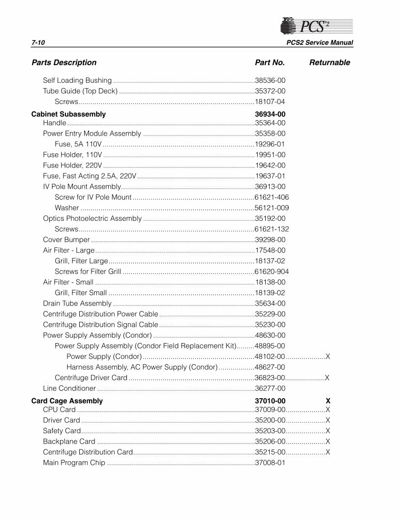
Parts Description Part No. Returnable
Self Loading Bushing .......................................................................38536-00Tube Guide (Top Deck) ....................................................................35372-00
Screws........................................................................................18107-04
Cabinet Subassembly 36934-00Handle ..............................................................................................35364-00Power Entry Module Assembly ........................................................35358-00
Fuse, 5A 110V ............................................................................19296-01Fuse Holder, 110V ............................................................................19951-00Fuse Holder, 220V ............................................................................19642-00Fuse, Fast Acting 2.5A, 220V...........................................................19637-01IV Pole Mount Assembly...................................................................36913-00
Screw for IV Pole Mount .............................................................61621-406Washer .......................................................................................56121-009
Optics Photoelectric Assembly ........................................................35192-00Screws........................................................................................61621-132
Cover Bumper ..................................................................................39298-00Air Filter - Large................................................................................17548-00
Grill, Filter Large.........................................................................18137-02Screws for Filter Grill ..................................................................61620-904
Air Filter - Small ................................................................................18138-00Grill, Filter Small .........................................................................18139-02
Drain Tube Assembly .......................................................................35634-00Centrifuge Distribution Power Cable ................................................35229-00Centrifuge Distribution Signal Cable ................................................35230-00Power Supply Assembly (Condor) ...................................................48630-00
Power Supply Assembly (Condor Field Replacement Kit).........48895-00Power Supply (Condor) ........................................................48102-00....................XHarness Assembly, AC Power Supply (Condor) ..................48627-00
Centrifuge Driver Card ...............................................................36823-00....................XLine Conditioner ...............................................................................36277-00
Card Cage Assembly 37010-00 XCPU Card .........................................................................................37009-00....................XDriver Card .......................................................................................35200-00....................XSafety Card.......................................................................................35203-00....................XBackplane Card ...............................................................................35206-00....................XCentrifuge Distribution Card.............................................................35215-00....................XMain Program Chip ..........................................................................37008-01
7-10 PCS2 Service Manual
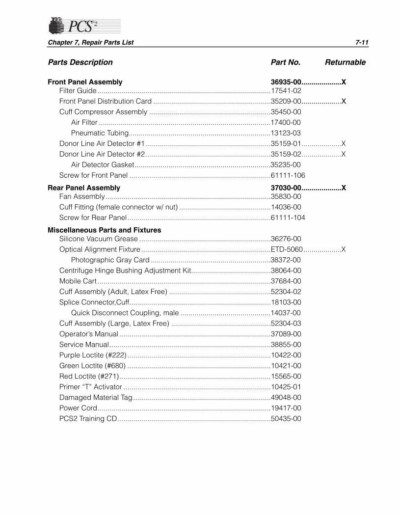
Chapter 7, Repair Parts List 7-11
Parts Description Part No. Returnable
Front Panel Assembly 36935-00....................XFilter Guide.......................................................................................17541-02Front Panel Distribution Card ...........................................................35209-00....................X
Cuff Compressor Assembly .............................................................35450-00Air Filter ......................................................................................17400-00Pneumatic Tubing.......................................................................13123-03
Donor Line Air Detector #1...............................................................35159-01....................XDonor Line Air Detector #2...............................................................35159-02....................X
Air Detector Gasket....................................................................35235-00Screw for Front Panel .......................................................................61111-106
Rear Panel Assembly 37030-00....................XFan Assembly...................................................................................35830-00Cuff Fitting (female connector w/ nut) ..............................................14036-00Screw for Rear Panel........................................................................61111-104
Miscellaneous Parts and FixturesSilicone Vacuum Grease ..................................................................36276-00Optical Alignment Fixture .................................................................ETD-5060...................X
Photographic Gray Card ............................................................38372-00Centrifuge Hinge Bushing Adjustment Kit........................................38064-00Mobile Cart .......................................................................................37684-00Cuff Assembly (Adult, Latex Free) ...................................................52304-02Splice Connector,Cuff.......................................................................18103-00
Quick Disconnect Coupling, male .............................................14037-00Cuff Assembly (Large, Latex Free) ..................................................52304-03Operator’s Manual ............................................................................37089-00Service Manual.................................................................................38855-00Purple Loctite (#222) ........................................................................10422-00Green Loctite (#680) ........................................................................10421-00Red Loctite (#271)............................................................................15565-00Primer “T” Activator ..........................................................................10425-01Damaged Material Tag.....................................................................49048-00Power Cord.......................................................................................19417-00PCS2 Training CD.............................................................................50435-00

U.S. Plasma customers are required to return certain used PCS2 parts toHaemonetics. The following procedure should be used by the customer toensure the proper steps and precautions are made when returning usedPCS2 parts to Haemonetics.
Note: This procedure should be used for returnable parts only. Please seethe PCS2 parts list earlier in this chapter for a list of PCS2returnable parts, or refer to the packing list accompanying the partordered. Occasionally a part’s return status may change and will notbe reflected in this chapter. The packing list reflects the most up todate return status of a part. Call the Haemonetics Hot Line (800-356-3506) if further clarification is needed. Nonreturnable partsshould be discarded by the center per the center’s SOP.
1. The center should call the Haemonetics Hot Line (800-356-3506) toorder parts as needed.
2. Upon receiving the replacement part, remove the replacement partfrom its box and install the part on the machine. Attach a completedblue DMT tag (which you can obtain from Haemonetics) to the usedpart and package it in the same box the replacement part came in. Useone DMT tag for each used part being returned.
Note: If the original box cannot be used, please repackage the part withyour own packaging material. Please be sure to protect the usedpart from shipping damage by filling the void in the box withbubble wrap or newspaper and make sure that electronic boards(i.e., processor card, driver card, etc.) are placed in Anti Static bags.If a part is damaged during return shipment, the center may beinvoiced for the cost of that part.
3. Place the packing slip that came with the replacement part, or a copy,into the box to be returned to Haemonetics. The packing slip can befound in a small pouch on the side of the replacement part’s box.
4. Ship the used part back to Haemonetics within 2 days of receivingreplacement parts. If the returned part is contaminated please packagethe part per your carrier’s biohazard shipping requirements. The cost ofshipping is to be incurred by the center as Haemonetics absorbs the costof shipping replacement parts. Send all parts to the following address:
Haemonetics Corp.Attn: Plasma Parts, RGA Dept.400 Wood RoadBraintree, MA 02184
Please note: The center may want to keep tracking information forreference purposes.
Note: If the part is not received within 30 days of receipt of the replacementpart, your facility will be invoiced for the cost of the part.
7-12 PCS2 Service Manual
Used PCS2Parts Return
Procedure
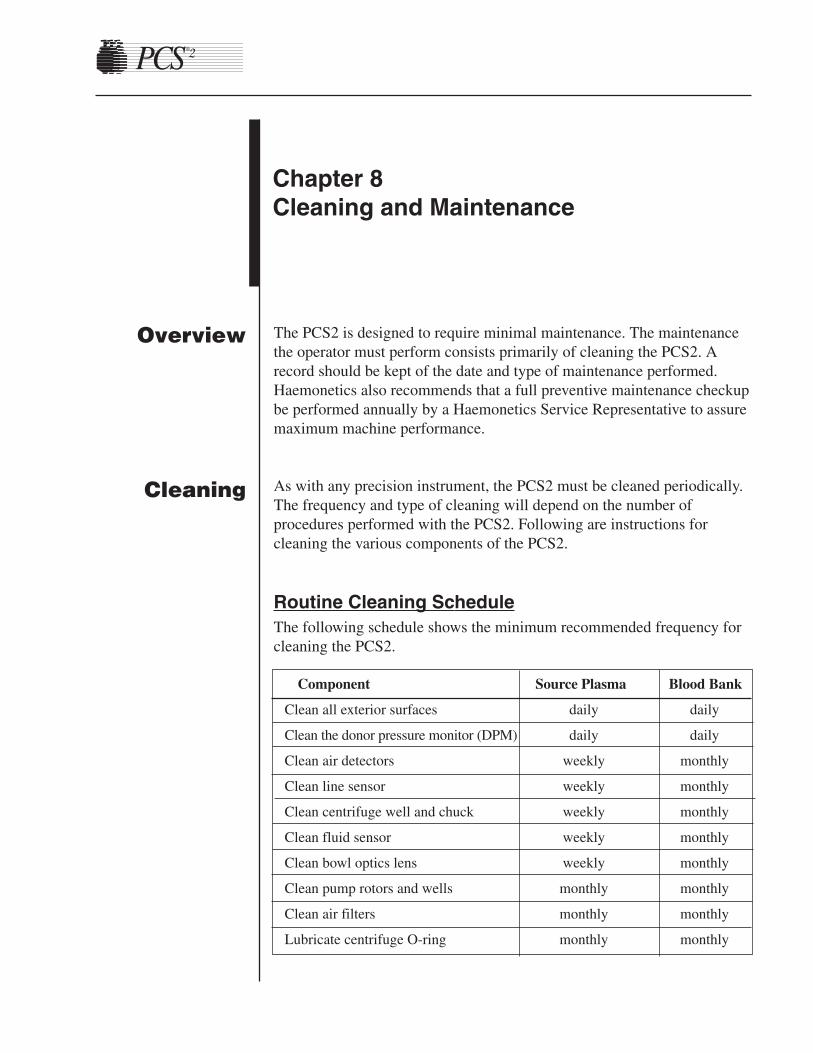
The PCS2 is designed to require minimal maintenance. The maintenancethe operator must perform consists primarily of cleaning the PCS2. Arecord should be kept of the date and type of maintenance performed.Haemonetics also recommends that a full preventive maintenance checkupbe performed annually by a Haemonetics Service Representative to assuremaximum machine performance.
As with any precision instrument, the PCS2 must be cleaned periodically.The frequency and type of cleaning will depend on the number ofprocedures performed with the PCS2. Following are instructions forcleaning the various components of the PCS2.
Routine Cleaning ScheduleThe following schedule shows the minimum recommended frequency forcleaning the PCS2.
Component Source Plasma Blood Bank
Clean all exterior surfaces daily daily
Clean the donor pressure monitor (DPM) daily daily
Clean air detectors weekly monthly
Clean line sensor weekly monthly
Clean centrifuge well and chuck weekly monthly
Clean fluid sensor weekly monthly
Clean bowl optics lens weekly monthly
Clean pump rotors and wells monthly monthly
Clean air filters monthly monthly
Lubricate centrifuge O-ring monthly monthly
Chapter 8Cleaning and Maintenance
Overview
Cleaning
Cleaning Supplies Needed1. Cleaning solution (recommended for use with bloodborne pathogens)
2. Clear, warm water
3. Distilled water
4. Lint-free gauze pads or towels
5. Protective gloves
6. Phillips head screwdriver
7. Silicone vacuum grease
8. Cotton swabs
9. Spray bottles
10. Owner’s Manual and/or Service Manual
11. Maintenance records or documentation logs
Warning!
Power off and unplug the PCS2 before cleaning to preventpotential danger of electrical shock.
Note: Throughout this chapter, some cleaning procedures reference usingdistilled water to clean components. We suggest using distilledwater as it is less likely to leave a film on the components.However, if distilled water is not available, use the clearest wateravailable at your center.
Cleaning the PCS2
Note: Certain commercial cleaning agents may not be compatible withcomponents on the PCS2. Several commonly used agents knownNOT to be compatible with the PCS2 are Pro-Tech, Dispatch,CitriGuard II and Alcohol. If there are questions regarding the useof a specific cleaning agent, call the Haemonetics Hotline with theManufacturer's Information on the cleaning agent and the cleaningagents Material Safety Data Sheet (MSDS).
Membrane Panel and Outer CabinetThe exterior of the PCS2, including the membrane panel, should becleaned with a cleaning solution at regular intervals as well as any time aspill has occurred. Do not spray cleaning solution directly on themembrane panel.
8-2 PCS2 Service Manual
!

Chapter 8, Cleaning and Maintenance 8-3
Donor Pressure Monitor (DPM)1. Depress and hold the white lock ring of the DPM into the case.
2. Wipe the external surface of the silver metal DPM tube using lint-freegauze or toweling moistened with clear water.
3. Using dry lint-free gauze or toweling dry the silver metal DPM tube.
4. Release the white lock ring.
Warning!
The use of alcohol or cleaning solution on the DPM may cause areaction with the DPM filter plastic resulting in a crack in theDPM filter and a loss of pressure in the DPM tubing.
Air DetectorsThe air detectors should be cleaned with distilled water at regular intervalsand whenever necessary to remove debris from lenses.
Note: A residue of powder from disposable gloves can cause an airdetector to incorrectly sense air. If a procedure stops due to an airdetector incorrectly sensing air, clean the air detector beforecontinuing the procedure.
1. Gently wash the grooves of the air detectors with lint-free gauze ortoweling moistened with distilled water.
2. Dry the grooves with lint-free gauze or toweling or a cotton-tippedswab.
Line SensorThe line sensor should be cleaned with distilled water at regular intervalsas well as any time a spill has occurred.
Note: Cleaning of the line sensor during a procedure may be necessary.Cleaning the line sensor during a procedure should be performedduring Return or in the Ready mode only.
Warning!
The line sensor must be clean to function properly. If it is notclean, it may interfere with the proper performance of theapheresis procedure.
!
!

1. Gently wash the groove of the line sensor with lint-free gauze ortoweling moistened with distilled water.
2. Dry the groove with lint-free gauze or toweling.
Figure 8-1, Centrifuge Well Components
Centrifuge WellFigure 8-1 is a view of the centrifuge well with components labeled. Referto this drawing to understand the cleaning instructions.
Warning!
Haemonetics recommends the use of rubber or vinyl gloves toavoid contact with any spilled blood. When handling or discardingpotentially contaminated waste, comply with the policies andprocedures dictated by the Center’s Infection Control Plan, aslegally required by OSHA’s Bloodborne Pathogens Standard.
8-4 PCS2 Service Manual
!
Cover
CentrifugeChuckWell
CentrifugeCover Latch
BowlOptics
FluidSensor
!
Chapter 8, Cleaning and Maintenance 8-5
Two biohazard waste bags are included with each PCS2. The bags arelocated under the machine on a tray. One of the bags is connected to thecentrifuge drain tube; a second is provided to replace the connected bag.Replacement bags may be ordered through the Haemonetics Hotline.
Steps for routine cleaning of the centrifuge well and cover
1. Wipe the centrifuge well and the chuck with a lint-free toweldampened with cleaning solution. Copious amounts of fluid are notnecessary for routine maintenance of the centrifuge.
Warning!
If the cleaning solution should come in contact with the bowloptics lens or fluid sensor, they should be wiped down with a towelmoistened with clear water and then dried in order to remove anyresidue.
2. Wipe the centrifuge cover with lint-free gauze or toweling moistenedwith cleaning solution.
3. Dry all surfaces using lint-free toweling.
4. To keep the O-ring at the base of the centrifuge chuck from cracking,apply a small amount of silicone vacuum grease onto the O-ring onceevery month. It is not necessary to remove the O-ring from thecentrifuge to apply silicone vacuum grease.
Steps for cleaning a fluid spill in the centrifuge well
1. Power off the machine and disconnect the power cord from the outlet.Ensure that the waste bag is attached to the drain tube and hangsfreely at the back of the machine.
Note: Clean with a recommended solution for bloodborne pathogens. Anyresidual blood should be cleaned using a 1:10 mixture of householdbleach and water or a commercially prepared germicidal cleaningproduct. This should be followed by wiping the centrifuge with acloth that has been sprayed with clear water.
2. Wipe the centrifuge cover with lint-free gauze or toweling moistenedwith cleaning solution. Dry all surfaces using lint-free toweling.
3. Wipe the centrifuge well and chuck with a lint-free towel dampenedwith cleaning solution avoiding the bowl optics. Repeat until all bloodcomponents are removed from the centrifuge well.
!
Warning!
If the cleaning solution should come in contact with the bowloptics lens or fluid sensor, they should be wiped down with atowel moistened with clear water and then dried in order toremove any residue.
4. If evidence of the spill is present in the biohazard waste bag, performthe following steps:
Note: Do not spray or pour fluid into the centrifuge well.
a. Obtain a syringe (50 ml or larger works best), spray bottle, orequivalent.
b. Attach a section of harness tubing to the syringe or spray bottle.The tubing should be long enough to reach from the syringe to theinside of the centrifuge drain holes.
c. Fill the syringe or spray bottle with cleaning solution.
d. Ensure that the drain tube is free from obstructions that couldinhibit the flow of fluid from the centrifuge to the drain cup. Placeend of tubing in the centrifuge drain holes and express cleaningsolution.
e. Repeat irrigation of drain holes until the drain tube is cleaned.Ensure that the attached biohazard waste bag does not overfill.Once the drain tube is cleaned, repeat irrigation with clean water.
f. Close the slide clamp of the used waste bag. Remove and disposeof the used biohazard waste bag. Replace with a new bag.
5. To keep the O-ring at the base of the centrifuge chuck from cracking,apply a small amount of silicone vacuum grease onto the O-ringfollowing a spill. It is not necessary to remove the O-ring from thecentrifuge to apply silicone vacuum grease.
6. The centrifuge should be spun for approximately 45 minutes to allowthe centrifuge to dry.
Procedure to spin centrifuge
Refer to the instructions below to spin the centrifuge in the Diagnosticsmode:1. Enter the Utilities mode by pressing the PLASMA key while
switching the power on.
2. Select the Diagnostics mode by pressing the MODIFY PROGRAMkey until the cursor points to Diagnostics and then press DRAW.
8-6 PCS2 Service Manual
!
Chapter 8, Cleaning and Maintenance 8-7
3. Select Centrifuge test mode by pressing the MODIFY PROGRAMkey until the cursor points to “Centrifuge” and then press DRAW.
4. Close and lock the centrifuge cover. A bowl is not required.
5. Press the DRAW key to start the centrifuge. Allow the centrifuge tospin for approximately 45 minutes.
6 Press the STOP key to stop the centrifuge.
7. Press the MODIFY PROGRAM key to exit the Centrifuge test mode.
8. Press the STOP key twice to exit the Utilities mode.
Fluid Sensor1. Clean the fluid sensor with a cotton swab moistened with clean water.
Dry the fluid sensor after cleaning.
Bowl Optics Lens1. Wipe the bowl optics lens with lint-free gauze or toweling moistened
with water.
2. Dry the bowl optics lens with dry lint-free gauze or toweling.
Warning!
In order to function properly, the bowl optics lens must be cleanand clear. A dirty or clouded lens could interfere with properfunction of the bowl optics.
Warning!
If cleaning solution should come in contact with the bowl opticslens, clean the lens with clear water and dry completely. Ensure nocloudiness or water spotting is present on the bowl optics lens aftercleaning.
!
!
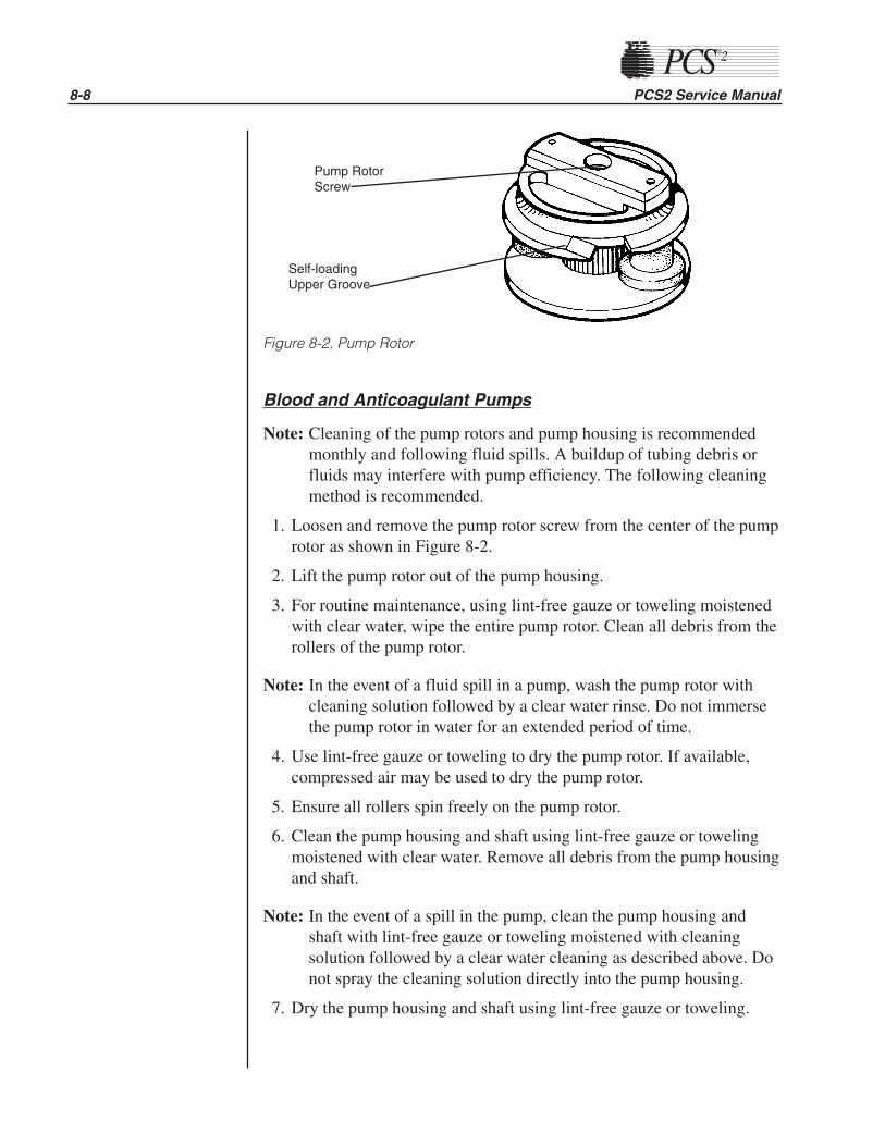
Figure 8-2, Pump Rotor
Blood and Anticoagulant Pumps
Note: Cleaning of the pump rotors and pump housing is recommendedmonthly and following fluid spills. A buildup of tubing debris orfluids may interfere with pump efficiency. The following cleaningmethod is recommended.
1. Loosen and remove the pump rotor screw from the center of the pumprotor as shown in Figure 8-2.
2. Lift the pump rotor out of the pump housing.
3. For routine maintenance, using lint-free gauze or toweling moistenedwith clear water, wipe the entire pump rotor. Clean all debris from therollers of the pump rotor.
Note: In the event of a fluid spill in a pump, wash the pump rotor withcleaning solution followed by a clear water rinse. Do not immersethe pump rotor in water for an extended period of time.
4. Use lint-free gauze or toweling to dry the pump rotor. If available,compressed air may be used to dry the pump rotor.
5. Ensure all rollers spin freely on the pump rotor.
6. Clean the pump housing and shaft using lint-free gauze or towelingmoistened with clear water. Remove all debris from the pump housingand shaft.
Note: In the event of a spill in the pump, clean the pump housing andshaft with lint-free gauze or toweling moistened with cleaningsolution followed by a clear water cleaning as described above. Donot spray the cleaning solution directly into the pump housing.
7. Dry the pump housing and shaft using lint-free gauze or toweling.
8-8 PCS2 Service Manual
Pump RotorScrew
Self-loadingUpper Groove
Chapter 8, Cleaning and Maintenance 8-9
Note: Be sure that the rotor is completely dry before returning it to thepump housing.
8. Install the pump rotor back into the pump housing.
Note: When installing the pump rotor, align the cross pin located in thepump rotor with the slot on the pump shaft so that the pump rotorcompletely seats into the pump housing.
Air FiltersThe PCS2 is equipped with air filters to filter dust from incoming cool air.The filters are located on the bottom of the cabinet and should be cleanedonce a month. Cleaning should be performed more frequently if machinesare operated in an unusually dusty environment or when particulate matteris visible on the filters. It is necessary to clean all air filters.
1. Remove the three retainer plates from the air filters with a Phillipshead screwdriver.
2. Pull the air filters out of the panel.
3. Rinse the air filters under warm running water only. DO NOT use anycleaning agents.
4. Gently squeeze the air filters to remove excess water.
5. Place the air filters on a clean, dry cloth and let dry completely.
Warning!
To avoid electrical shock do not place a wet air filter into themachine.
6. Reinsert the air filters into the panel assuring the openings arecompletely covered by the air filters.
7. Replace the retainer plates over the air filters.
Internal Chassis
Warning!
To avoid electrical shock ensure the machine is powered off andthe power cord is unplugged from the electrical outlet.
!
!

GuidelinesIf the machines are operated in an unusually dusty environment, it isrecommended that you periodically inspect the interior of the machinesfor any collection of dust. The frequency of this check should bedetermined by each individual center based upon their operatingenvironment.
If dust is present, the easiest methods of removing the dust are the use of aportable vacuum cleaner or compressed air.
For areas inside the machine that a portable vacuum cleaner cannot reach,use a small, clean paintbrush or equivalent to gently “sweep” the dustfrom these areas to an area where you can use the portable vacuumcleaner.
The Haemonetics PCS2 is checked for leakage current as part of its finalinspection before release. It will be checked on a yearly basis as part ofthe Preventive Maintenance (PM) program.
More frequent current leakage checks should be performed whenever amajor spill occurs on the PCS2. To determine the necessity of a leakagecurrent check after a major spill, the qualified trained staff should do thefollowing:
1. Disconnect the donor and remove the machine from service.
2. Thoroughly clean the spill from the machine.
3. Remove the front and back panels of the PCS2 case.
4. Visually inspect for fluid leakage inside the machine.
5. If the inside of the machine is free of fluid, no current leakage checkis necessary and the front and back panels can be replaced.
The PCS2 can then be returned to service.
6. If fluid is found on the inside of the machine, it should be cleaned anda current leakage check should be performed by a qualified centerpersonnel or Haemonetics Field Service Engineer before the machinecan be returned to the donor floor.
7. The earth ground leakage must not exceed 100 microamperes at 120VAC or 500 microamperes at 240 VAC to pass inspection.
8-10 PCS2 Service Manual
LeakageCurrentCheck
Chapter 8, Cleaning and Maintenance 8-11
Warning!
Leakage current is a primary indication of electrical shock hazard.Each PCS2 is carefully checked during final factory inspection toverify that leakage current meets the values specified above in step7, and is rechecked on a regular basis by Haemonetics as part ofannual preventive maintenance.
The Returned Goods Authorization (RGA) system outlines the proceduresto be followed when returning goods. The system assures that returnedgoods are properly handled and analyzed. Because of the potential healthhazard inherent in the shipment, handling, and defect analysis ofbiologically contaminated products, it is important that these proceduresbe carefully followed.
RGA ProcedureThe steps that should be followed in returning any equipment are outlinedbelow. All disposables to be picked up by courier for return toHaemonetics should be handled according to the Haemonetics Hot Lineinstructions. Merchandise shipped in error by Haemonetics will behandled by the Customer Services Department (800) 356-3506.
1. Call the Haemonetics Hot Line listed previously in this chapter, forreturn of any product felt to be unacceptable for patient, donor, orblood bank use.
2. The Hot Line coordinator will request the following information:
a) product List Number,
b) product Lot Number,
c) the quantity to be returned,
d) the defect noted.
3. Major events, i.e., those that result in a spill or red blood cell loss mustbe reported immediately. Examples include any bowl leaks, holes orcracks in bowl body, as well as any new or unusual defects that havethe potential to result in contamination of the fluid path or could causea spill or leak if the bowl were used. It is extremely important that youdo not dispose of such bowls unless so instructed by the HaemoneticsComplaint Coordinator.
Return GoodsAuthorization
(RGA)
!
4. The Haemonetics representative will inform you of what additionalsteps need to be taken at this point.
5. If the disposables have been exposed to blood, you must provide adetailed description of the problem you experienced. You must alsosupply the same information as detailed earlier, i.e., product listnumber, lot number, etc. In many situations, you will be asked todispose of these goods after reporting the defect.
6. Should Haemonetics request the return of contaminated disposables,or equipment, the disposables or equipment must be decontaminatedprior to shipment pursuant to those policies and procedures dictatedby the medical facility’s Infection Control Plan, as required byOSHA’s Bloodborne Pathogens Standard. Repackaging of equipmentor disposables for return to Haemonetics must comply with U.S.Department of Transportation regulations for interstate shipment ofblood contaminated products.
Warning!
Bloody materials, if returned unwashed, cannot be analyzed andpose a potentially serious health hazard to individuals involved inshipping, handling, and testing.
Haemonetics takes pride in manufacturing clean and safe equipment anddisposables for our customers. In the event that there should be anyproblems with our product in any way, a toll free product assistance hot line number has been established to handle customer needs.A representative may be contacted during business hours, 8:30 a.m. to5:30 p.m. EST at (800) 356-3506.
8-12 PCS2 Service Manual
HaemoneticsQuality
Program
!