Haemonetics PCS2 - Operation Manual
54
0123 2 R PCS Printed in France Haemonetics Corporation 400 Wood Road Braintree, MA, 02184, USA P/N 85266-30, Manual revision: A ©2002, Haemonetics International. All rights reserved. April 2002 Working with the Haemonetics ® PCS ® 2 - Operation Manual -
-
Upload
emerson-ceras-davila -
Category
Documents
-
view
643 -
download
6
Transcript of Haemonetics PCS2 - Operation Manual

0123
2R
PCS
Printed in France Haemonetics Corporation400 Wood RoadBraintree, MA, 02184, USA P/N 85266-30, Manual revision: A©2002, Haemonetics International. All rights reserved. April 2002
Working with the Haemonetics® PCS®2- Operation Manual -


Preface iii
P/N 85266-30, Manual revision: A
CONSUMER INFORMATION
Proprietary rights The contents of this manual are property of the Haemonetics Corporation.Haemonetics® and PCS®2 are registered trademarks of the Haemonetics Corpo-ration. Any information or descriptions contained in this manual may not bereproduced and released to any of the general public, or used in conjunction withany professional instruction without written consent of Haemonetics Corpo-ration, USA. Please direct any written inquiries to the appropriate address:
Legal disclaimer This manual is intended for use as a guide, uniquely for material as supplied bythe Haemonetics Corporation. It provides the operator with necessary informa-tion to safely carry out specific procedures and satisfactorily maintain Haemo-netics-produced equipment. The manual is to be used in conjunction withinstruction and training as supplied by qualified Haemonetics personnel.
Haemonetics guarantees its products when correctly used by a properly trainedoperator. Any failure to respect the procedures as described could result inimpaired function of the equipment, as well as in injury to the operator and/orpatient /donor. Haemonetics accepts no responsibility for problems resultingfrom failure to comply with prescriptions as outlined by the company. Any modi-fications estimated as necessary by the customer should be evaluated by aHaemonetics Clinical Specialist.
Safe utilization of Haemonetics material and equipment requires the operator tocorrectly handle and dispose of blood-contaminated material. The operator ofany Haemonetics equipment must understand and implement the local policiesand standard operating procedures concerning the handling of blood-contami-nated material, as well as blood products.
It remains solely the responsibility of the customer to fully assess and ensure thesafety of any products obtained from Haemonetics prescribed procedures, priorto further application or use. Haemonetics declines any responsibility for choicesmade by the consumer concerning the utilization of products and by-products.
In addition, it is the responsibility of the apheresis center using Haemoneticsequipment and material to inform the donor about the risks involved with anyapheresis procedure. Prior to initiating any procedure, the apheresis center isresponsible to verify that the donor understands these risks and consents to theprocedure.
International HeadquartersHaemonetics S.A. Signy Center, P.O. Box 262CH-1274 Signy 2 SwitzerlandTel. +41-22-363-9011Fax +41-22-363-9054
Corporate HeadquartersHaemonetics Corporation400 Wood RoadBraintree, MA, 02184, USATel. +1-781-848-7100Fax +1-781-356-3558

iv Preface
P/N 85266-30, Manual revision: A
Haemonetics worldwide locations
Haemonetics Asia Inc. Taiwan Branch26F-1, No. 102 Roosevelt Road Sec. 2 Taipei, TaiwanTel. +886-2-2369-0722Fax +886-2-2364-3698
Haemonetics GesmbHHandelsges.m.b.H.Berlagasse 45/B2-02A-1210 Wien, AustriaTel. +43-1-294-29-00Fax +43-1-294-29-05
Haemonetics Belgium NVLeuvensesteenweg 542-BP. 14Planet II ComplexB-1930 Zaventem, BelgiumTel. +32-2-720-7484Fax +32-2-720-7155
Haemonetics BVC/O CITCO - WTC, PB 7241Strawinskylaan 17251007 JE AmsterdamThe NetherlandsTel. +31-35-602-3425Fax +31-35-602-4198
Haemonetics Medical Devices(Shanghai) International Trading Co. Ltd.Room 28032, Shanghai HSBC Tower101 Yin Cheng East RoadShangai 200120, PRCTel. +86-21-506-63366Fax +86-21-684-13688
Haemonetics CZ, spol. S.r.oPtašínského C.860200 Brno, Czech RepublicTel. +42-05-412-122400Fax +42-05-412-122399
Haemonetics France S.A.R.L. 46 bis, rue Pierre CurieZ.I. Les Gatines F-78370 Plaisir, FranceTel. +33-1-30-81-4141Fax +33-1-30-81-4130
Haemonetics GmbHRohrauerstrasse 72D-81477 München, GermanyTel. +49-89-785-8070 Fax +49-89-780-9779
Haemonetics Hong Kong Ltd. Suite 1314, Two Pacific Place88 Queensway, Hong Kong Tel. +852-286-89218 Fax +852-280-14380
Haemonetics Italia S.R.L.Via Donizetti, 3020020 Lainate (MI), ItalyTel. +39-2-935-70113Fax +39-2-935-72132
Haemonetics Japan K.K.Kyodo Building 3F16, Ichiban-cho, Chiyoda-kuTokyo, Japan, 102-0082Tel. +81-3-3237-7260Fax +81-3-3237-7330
Haemonetics Scandinavia ABBeta Huset, IdeonScheelegatan 17S-223 70 Lund, SwedenTel. +46-46-286-2320Fax +46-46-286-2321

Preface v
P/N 85266-30, Manual revision: A
Haemonetics (UK) Ltd.Beechwood HouseBeechwood EstateElmete Lane, RoundhayLeeds LS8 2LQ, United KingdomTel. +44-113-273-7711Fax +44-113-273-4055
Haemonetics S.A.Signy CentreP.O. Box 262CH-1274 Signy 2, SwitzerlandTel. +41-22-363- 9011Fax +41-22-363- 9054


P/N 85266-30, Manual revision: A
Table of Contents
Chapter 1 Explaining General Information
PROVIDING AN OVERVIEW. . . . . . . . . . . . . . . . . . . . . . . . . . . . . . . . . . . . 1-2
What is apheresis technology? . . . . . . . . . . . . . . . . . . . . . . . . . . . . . . . 1-2What is the purpose of this manual? . . . . . . . . . . . . . . . . . . . . . . . . . . . 1-2What is the Haemonetics Plasma Collection System 2?. . . . . . . . . . . . . 1-3What are the characteristics and features of the PCS2? . . . . . . . . . . . . . 1-3What are the special features of the PCS2? . . . . . . . . . . . . . . . . . . . . . . 1-4What is required to perform a procedure? . . . . . . . . . . . . . . . . . . . . . . . 1-4
UNDERSTANDING THE USE OF SYMBOLS . . . . . . . . . . . . . . . . . . . . . . . . 1-5Symbols found in this document . . . . . . . . . . . . . . . . . . . . . . . . . . . . . . 1-5Symbols found on the device . . . . . . . . . . . . . . . . . . . . . . . . . . . . . . . . 1-5Symbols found on disposable packaging. . . . . . . . . . . . . . . . . . . . . . . . 1-8
LISTING DEVICE SPECIFICATIONS . . . . . . . . . . . . . . . . . . . . . . . . . . . . . . . 1-9
Chapter 2 Describing the PCS2 Device Components
PRESENTING THE PCS2 DEVICE COMPONENTS . . . . . . . . . . . . . . . . . . . 2-3DESCRIBING THE CENTRIFUGE SYSTEM . . . . . . . . . . . . . . . . . . . . . . . . . 2-4
System-sealing mechanism . . . . . . . . . . . . . . . . . . . . . . . . . . . . . . . . . 2-5Centrifuge well . . . . . . . . . . . . . . . . . . . . . . . . . . . . . . . . . . . . . . . . . . 2-6Centrifuge base . . . . . . . . . . . . . . . . . . . . . . . . . . . . . . . . . . . . . . . . . . 2-6
DESCRIBING THE PCS2 CABINET COMPONENTS . . . . . . . . . . . . . . . . . . 2-7Optical line Sensor . . . . . . . . . . . . . . . . . . . . . . . . . . . . . . . . . . . . . . . 2-7Weigher . . . . . . . . . . . . . . . . . . . . . . . . . . . . . . . . . . . . . . . . . . . . . . . 2-7Pumps. . . . . . . . . . . . . . . . . . . . . . . . . . . . . . . . . . . . . . . . . . . . . . . . . 2-8Valves . . . . . . . . . . . . . . . . . . . . . . . . . . . . . . . . . . . . . . . . . . . . . . . . . 2-9Donor flow lights . . . . . . . . . . . . . . . . . . . . . . . . . . . . . . . . . . . . . . . 2-10Air detectors . . . . . . . . . . . . . . . . . . . . . . . . . . . . . . . . . . . . . . . . . . . 2-11Pressure monitors . . . . . . . . . . . . . . . . . . . . . . . . . . . . . . . . . . . . . . . 2-13Blood filter holder. . . . . . . . . . . . . . . . . . . . . . . . . . . . . . . . . . . . . . . 2-14Solution-bag poles (2) . . . . . . . . . . . . . . . . . . . . . . . . . . . . . . . . . . . . 2-14Power entry module . . . . . . . . . . . . . . . . . . . . . . . . . . . . . . . . . . . . . 2-15Power cord . . . . . . . . . . . . . . . . . . . . . . . . . . . . . . . . . . . . . . . . . . . . 2-15Pressure cuff . . . . . . . . . . . . . . . . . . . . . . . . . . . . . . . . . . . . . . . . . . . 2-15Biohazard waste bag. . . . . . . . . . . . . . . . . . . . . . . . . . . . . . . . . . . . . 2-15Communication box/data card (optional) . . . . . . . . . . . . . . . . . . . . . 2-16Bar code reader (optional). . . . . . . . . . . . . . . . . . . . . . . . . . . . . . . . . 2-16

viii Table of Contents
P/N 85266-30, Manual revision: A
DESCRIBING THE PCS2 CONTROL PANEL . . . . . . . . . . . . . . . . . . . . . . . 2-17Display screen . . . . . . . . . . . . . . . . . . . . . . . . . . . . . . . . . . . . . . . . . . 2-17Mode control keys . . . . . . . . . . . . . . . . . . . . . . . . . . . . . . . . . . . . . . . 2-19Protocol key. . . . . . . . . . . . . . . . . . . . . . . . . . . . . . . . . . . . . . . . . . . . 2-19Pump control keys . . . . . . . . . . . . . . . . . . . . . . . . . . . . . . . . . . . . . . . 2-20Programming keys . . . . . . . . . . . . . . . . . . . . . . . . . . . . . . . . . . . . . . . 2-20Cuff key . . . . . . . . . . . . . . . . . . . . . . . . . . . . . . . . . . . . . . . . . . . . . . . 2-21Valve control keys . . . . . . . . . . . . . . . . . . . . . . . . . . . . . . . . . . . . . . . 2-21
Chapter 3 Maintaining the PCS2 Equipment
CLEANING PROCEDURES . . . . . . . . . . . . . . . . . . . . . . . . . . . . . . . . . . . . . 3-2Cabinet, control panel and valves . . . . . . . . . . . . . . . . . . . . . . . . . . . . 3-2Pressure monitors. . . . . . . . . . . . . . . . . . . . . . . . . . . . . . . . . . . . . . . . . 3-3Air detectors . . . . . . . . . . . . . . . . . . . . . . . . . . . . . . . . . . . . . . . . . . . . 3-3Optical sensors . . . . . . . . . . . . . . . . . . . . . . . . . . . . . . . . . . . . . . . . . . 3-3Fluid detector. . . . . . . . . . . . . . . . . . . . . . . . . . . . . . . . . . . . . . . . . . . . 3-4Centrifuge components . . . . . . . . . . . . . . . . . . . . . . . . . . . . . . . . . . . . 3-4Pumps . . . . . . . . . . . . . . . . . . . . . . . . . . . . . . . . . . . . . . . . . . . . . . . . . 3-5Filter screens . . . . . . . . . . . . . . . . . . . . . . . . . . . . . . . . . . . . . . . . . . . . 3-5Barcode reader. . . . . . . . . . . . . . . . . . . . . . . . . . . . . . . . . . . . . . . . . . . 3-5
CUSTOMER SERVICE . . . . . . . . . . . . . . . . . . . . . . . . . . . . . . . . . . . . . . . . . 3-6Clinical training . . . . . . . . . . . . . . . . . . . . . . . . . . . . . . . . . . . . . . . . . . 3-6Field service. . . . . . . . . . . . . . . . . . . . . . . . . . . . . . . . . . . . . . . . . . . . . 3-6Returned Goods Authorization system . . . . . . . . . . . . . . . . . . . . . . . . . 3-6
HAEMONETICS® CLEANING AND MAINTENANCE RECORD. . . . . . . . . 3-8
Chapter 4 Ensuring Safety and Quality for a PCS2 ProcedureHANDLING THE PCS2 EQUIPMENT . . . . . . . . . . . . . . . . . . . . . . . . . . . . . 4-2
Storing the PCS2 device and material. . . . . . . . . . . . . . . . . . . . . . . . . . 4-2Inspecting the material . . . . . . . . . . . . . . . . . . . . . . . . . . . . . . . . . . . . . 4-2
PREVENTING PROBLEMS DURING A PCS2 PROCEDURE. . . . . . . . . . . . . 4-3Understanding the risk of hemolysis. . . . . . . . . . . . . . . . . . . . . . . . . . . 4-3Avoiding the consequences of flow restriction . . . . . . . . . . . . . . . . . . . 4-3Avoiding bowl misalignment . . . . . . . . . . . . . . . . . . . . . . . . . . . . . . . . 4-4Avoiding overheating due to mechanical situations . . . . . . . . . . . . . . . 4-4Controlling for Red Cell Overrun . . . . . . . . . . . . . . . . . . . . . . . . . . . . . 4-4
WARNINGS FOR THE OPERATOR. . . . . . . . . . . . . . . . . . . . . . . . . . . . . . . 4-5Electrical shock hazards . . . . . . . . . . . . . . . . . . . . . . . . . . . . . . . . . . . . 4-5Leakage current control . . . . . . . . . . . . . . . . . . . . . . . . . . . . . . . . . . . 4-5Mechanical hazards/rotating parts . . . . . . . . . . . . . . . . . . . . . . . . . . . . 4-5Power outlet connection . . . . . . . . . . . . . . . . . . . . . . . . . . . . . . . . . . . 4-5Communicable disease precautions . . . . . . . . . . . . . . . . . . . . . . . . . . . 4-6

P/N 85266-30, Manual revision: A
Chapter 1
Explaining General Information
PROVIDING AN OVERVIEW . . . . . . . . . . . . . . . . . . . . . . . . . . . . . . . . . . . 1-2What is apheresis technology? . . . . . . . . . . . . . . . . . . . . . . . . . . . . . . . 1-2What is the purpose of this manual? . . . . . . . . . . . . . . . . . . . . . . . . . . . 1-2What is the Haemonetics Plasma Collection System 2? . . . . . . . . . . . . 1-3What are the characteristics and features of the PCS2? . . . . . . . . . . . . . 1-3What are the special features of the PCS2? . . . . . . . . . . . . . . . . . . . . . . 1-4What is required to perform a procedure?. . . . . . . . . . . . . . . . . . . . . . . 1-4
UNDERSTANDING THE USE OF SYMBOLS . . . . . . . . . . . . . . . . . . . . . . . . 1-5Symbols found in this document. . . . . . . . . . . . . . . . . . . . . . . . . . . . . . 1-5Symbols found on the device . . . . . . . . . . . . . . . . . . . . . . . . . . . . . . . . 1-5Symbols found on disposable packaging . . . . . . . . . . . . . . . . . . . . . . . 1-8
LISTING DEVICE SPECIFICATIONS . . . . . . . . . . . . . . . . . . . . . . . . . . . . . . . 1-9
1-2 Explaining General Information
P/N 85266-30, Manual revision: A
PROVIDING AN OVERVIEW
What is apheresis technology?
Apheresis is the general term used to describe the separation, selective removaland collection of one or more of the individual components which together formwhole blood. This term can be subdivided into two categories:
Cytapheresis: selective removal of one or more of the formed, cellularcomponents of whole blood. These elements include erythrocytes,thrombocytes and leukocytes.
Plasmapheresis: selective removal of plasma, the liquid suspension me-dium of blood. Plasma contains elements referred to as fractionablecomponents, such as clotting proteins and immunoglobulins.
Apheresis technology permits:
The collection and separation of whole blood.
The selective removal and collection of specific components.
The subsequent return of the non-selected components to the donoror patient.
What is the purpose of this manual?
This manual is intended to supply anyone involved in using Haemonetics equip-ment with the essential tool for safe and successful operation – information.Using this tool of information, the operator can acquire knowledge to be appliedthroughout all levels of operating experience. This body of information should beconsulted whenever necessary, starting from the initial contact with Haemoneticstechnology to attain:
An awareness of the purpose of the device and the implications of its col-lection procedures for the donor and the apheresis center.
An understanding of how to safely operate the Haemonetics system, cor-rectly install the appropriate disposable material, and troubleshoot anydifficulties.
An ability to consistently apply the principles behind safe operation,proper maintenance and correct handling to ensure optimal, qualityapheresis results.
Explaining General Information 1-3
P/N 85266-30, Manual revision: A
What is the Haemonetics Plasma Collection System 2?
Using updated apheresis technology, Haemonetics has produced the PCS2 - acompact, lightweight plasmapheresis system which is as easy and safe to use asit is technologically advanced.
The PCS2 automated apheresis technology provides the operator with amaximum degree of flexibility in any type of plasmapheresis location. Theplasma collected may be designated for use in therapeutic transfusion. It may alsobe conserved, used as source plasma and subsequently fractionated into plasma-derived products.
What are the characteristics and features of the PCS2?
The PCS2 is appropriately called a Plasma Collection System because it consistsof distinctive parts which collectively function as a whole system to produce adesignated final product:
The automated plasmapheresis device developed by Haemoneticscalled the PCS2.
The process designed by Haemonetics to gather plasma from a donorcalled a collection procedure.
The single-use collection material manufactured by Haemonetics calleda disposable set.
Once the operator has initiated a PCS2 procedure, plasma collection willproceed automatically. The appropriate amount of anticoagulant solution will bemixed in the disposable tubing with whole blood from the donor. This anticoag-ulated blood will be drawn into a disposable collection bowl and separated bycentrifugal force into its various components.
When the bowl reaches its collection capacity, the plasma component will exitthe bowl and be directed into a plasma collection container for conservation.Non-selected blood components will be returned to the donor. This cycle will berepeated until the desired amount of plasma is collected.
The choice of the disposable collection material will depend on the desiredcollection product. The PCS2 technology also provides the operator with theoption to infuse saline solution along with the blood components to the donor atdifferent points of a procedure, depending on the type of disposable bowl in use.
Haemonetics has designed the PCS2 technology with a degree of automationwhich permits the operator to interact with the device. The operator shouldremain attentive to the display screen messages while monitoring the status of thedonor. It is possible to modify certain aspects of the collection procedures, basedon the needs and requirements of the individual donor and the selected material.

1-4 Explaining General Information
P/N 85266-30, Manual revision: A
What are the special features of the PCS2?
Haemonetics has incorporated advanced technological features into the portablePCS2 design. Examples of these features, which ensure safety for the donor andpermit efficient time-management for the operator, are:
Self-loading pumps.
Advanced optical sensors.
Donor-line tubing pressure monitor.
Communication data box or internal data card.
Barcode reader.
What is required to perform a procedure?
PCS2 collection procedures are quick and simple to perform. The followingmaterial is required to perform a PCS2 procedure:
A PCS2 disposable set designed for the selected procedure.
Venipuncture materials and hemostats.
Appropriate anticoagulant solution.
0.9% normal saline (optional).
The operator will need to:
Install the appropriate disposable set.
Modify any settings if necessary.
Perform a single venous puncture, prior to initiating a procedure.
Plasma collection will proceed automatically until the end-collection target hasbeen reached.
Explaining General Information 1-5
P/N 85266-30, Manual revision: A
UNDERSTANDING THE USE OF SYMBOLS
Symbols found in this document
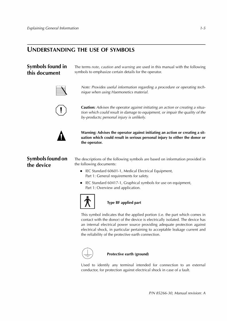
The terms note, caution and warning are used in this manual with the followingsymbols to emphasize certain details for the operator.
Note: Provides useful information regarding a procedure or operating tech-nique when using Haemonetics material.
Caution: Advises the operator against initiating an action or creating a situa-tion which could result in damage to equipment, or impair the quality of theby-products; personal injury is unlikely.
Warning: Advises the operator against initiating an action or creating a sit-uation which could result in serious personal injury to either the donor orthe operator.
Symbols found on the device
The descriptions of the following symbols are based on information provided inthe following documents:
IEC Standard 60601-1, Medical Electrical Equipment, Part 1: General requirements for safety.
IEC Standard 60417-1, Graphical symbols for use on equipment, Part 1: Overview and application.
Type BF applied part
This symbol indicates that the applied portion (i.e. the part which comes incontact with the donor) of the device is electrically isolated. The device hasan internal electrical power source providing adequate protection againstelectrical shock, in particular pertaining to acceptable leakage current andthe reliability of the protective earth connection.
Protective earth (ground)
Used to identify any terminal intended for connection to an externalconductor, for protection against electrical shock in case of a fault.

1-6 Explaining General Information
P/N 85266-30, Manual revision: A
~ Alternating current
Used to indicate on the rating plate that the device is suitable for alternatingcurrent only.
Fuse symbol
Used to identify fuse boxes or the location of a fuse box.
Power OFF
Position of the main power switch indicating disconnection from the mains.
Power ON
Position of the main power switch indicating connection to the mains.
IPX1 Protection against ingress of liquid
Indicates that the enclosure of the device is designed to provide a specifieddegree of protection against harmful ingress of water or liquid into the equip-ment (under applicable conditions).
Attention (Consult accompanying documents)
Non-ionizing electromagnetic radiation
Used to specify RF transmission for data communication.

Explaining General Information 1-7
P/N 85266-30, Manual revision: A
The following symbols have been designed for devices manufactured by Haemonetics:
Bar-code reader connection
RS232 connection
RS232 connection with power to one pin
Pressure cuff connection
1-8 Explaining General Information
P/N 85266-30, Manual revision: A
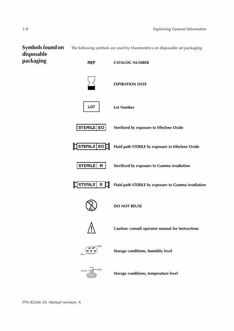
Symbols found on disposable packaging
The following symbols are used by Haemonetics on disposable set packaging.
CATALOG NUMBER
EXPIRATION DATE
Lot Number
Sterilized by exposure to Ethylene Oxide
Fluid path STERILE by exposure to Ethylene Oxide
Sterilized by exposure to Gamma irradiation
Fluid path STERILE by exposure to Gamma irradiation
DO NOT REUSE
Caution: consult operator manual for instructions
Storage conditions, humidity level
Storage conditions, temperature level
REF
LOT
80%
8%

Explaining General Information 1-9
P/N 85266-30, Manual revision: A
LISTING DEVICE SPECIFICATIONS The approximate weight and dimensions of the PCS2 device are as follows:
The following environmental conditions should be respected pertaining to oper-ation and storage of the PCS2 device:
The electrical specifications for operating the PCS2 device are as follows:
Note: Haemonetics will regulate the proper voltage setting upon installation.The power source used must be properly grounded.
CharacteristicsValues
Cabinet cover open
Cabinet cover closed
Height 63 cm 44 cm
Width 55 cm
Depth 55 cm 32 cm
Depth with communication box 55 cm 37 cm
Weight 26.4 kg
Weight with communication box 27.4 kg
Conditions Values
Ambient operating temperature +18° C to +27° C
Tested storage temperature 0° C to + 40° C
Storage humidity level Maximum relative humidity rate of 90%, non-condensing
Characteristics Values(relative to input voltage)
Input voltage 230 VAC ± 10% 110 VAC ± 10%
Operating current ~1.9 A ~ 2.6 A
Fuse rating F2.5 A @ 250 V F5.0 A @ 250 V
Operating frequency range 50 - 60 Hz 50 - 60 Hz
Maximum leakage current 500 µA 100 µA
1-10 Explaining General Information
P/N 85266-30, Manual revision: A
Caution: The PCS2 device must be operated in an environment compatible to therequirements of the IEC 60601-1-2 Standard, Electromagnetic compatibility.
Mobile RF communication equipment not approved by Haemonetics and porta-ble communication equipment can affect the PCS2 device. Any accessories andcables not approved by Haemonetics used in conjunction with the device mayincrease hazards and influence compatibility with EMC requirements. Therefore,non-approved accessories and cables must not be used.
In addition, the PCS2 device and accessories must not be placed directly adja-cent to, or top of other equipment, unless specifically approved by Haemonetics.

P/N 85266-30, Manual revision: A
Chapter 2
Describing the PCS2 Device Components
PRESENTING THE PCS2 DEVICE COMPONENTS. . . . . . . . . . . . . . . . . . . . 2-3DESCRIBING THE CENTRIFUGE SYSTEM . . . . . . . . . . . . . . . . . . . . . . . . . . 2-4
System-sealing mechanism . . . . . . . . . . . . . . . . . . . . . . . . . . . . . . . . . . 2-5Centrifuge well . . . . . . . . . . . . . . . . . . . . . . . . . . . . . . . . . . . . . . . . . . . 2-6Centrifuge base. . . . . . . . . . . . . . . . . . . . . . . . . . . . . . . . . . . . . . . . . . . 2-6
DESCRIBING THE PCS2 CABINET COMPONENTS. . . . . . . . . . . . . . . . . . . 2-7Optical line Sensor . . . . . . . . . . . . . . . . . . . . . . . . . . . . . . . . . . . . . . . . 2-7Weigher . . . . . . . . . . . . . . . . . . . . . . . . . . . . . . . . . . . . . . . . . . . . . . . . 2-7Pumps . . . . . . . . . . . . . . . . . . . . . . . . . . . . . . . . . . . . . . . . . . . . . . . . . 2-8Valves. . . . . . . . . . . . . . . . . . . . . . . . . . . . . . . . . . . . . . . . . . . . . . . . . . 2-9Donor flow lights . . . . . . . . . . . . . . . . . . . . . . . . . . . . . . . . . . . . . . . . 2-10Air detectors . . . . . . . . . . . . . . . . . . . . . . . . . . . . . . . . . . . . . . . . . . . . 2-11Pressure monitors . . . . . . . . . . . . . . . . . . . . . . . . . . . . . . . . . . . . . . . . 2-13Blood filter holder . . . . . . . . . . . . . . . . . . . . . . . . . . . . . . . . . . . . . . . 2-14Solution-bag poles (2). . . . . . . . . . . . . . . . . . . . . . . . . . . . . . . . . . . . . 2-14Power entry module . . . . . . . . . . . . . . . . . . . . . . . . . . . . . . . . . . . . . . 2-15Power cord. . . . . . . . . . . . . . . . . . . . . . . . . . . . . . . . . . . . . . . . . . . . . 2-15Pressure cuff . . . . . . . . . . . . . . . . . . . . . . . . . . . . . . . . . . . . . . . . . . . . 2-15Biohazard waste bag . . . . . . . . . . . . . . . . . . . . . . . . . . . . . . . . . . . . . 2-15Communication box/data card (optional) . . . . . . . . . . . . . . . . . . . . . . 2-16Bar code reader (optional) . . . . . . . . . . . . . . . . . . . . . . . . . . . . . . . . . 2-16
DESCRIBING THE PCS2 CONTROL PANEL . . . . . . . . . . . . . . . . . . . . . . . 2-17Display screen . . . . . . . . . . . . . . . . . . . . . . . . . . . . . . . . . . . . . . . . . . 2-17Mode control keys . . . . . . . . . . . . . . . . . . . . . . . . . . . . . . . . . . . . . . . 2-19Protocol key . . . . . . . . . . . . . . . . . . . . . . . . . . . . . . . . . . . . . . . . . . . . 2-19Pump control keys . . . . . . . . . . . . . . . . . . . . . . . . . . . . . . . . . . . . . . . 2-20Programming keys . . . . . . . . . . . . . . . . . . . . . . . . . . . . . . . . . . . . . . . 2-20Cuff key . . . . . . . . . . . . . . . . . . . . . . . . . . . . . . . . . . . . . . . . . . . . . . . 2-21Valve control keys . . . . . . . . . . . . . . . . . . . . . . . . . . . . . . . . . . . . . . . 2-21
2-2 Describing the PCS2 Device Components
P/N 85266-30, Manual revision: A
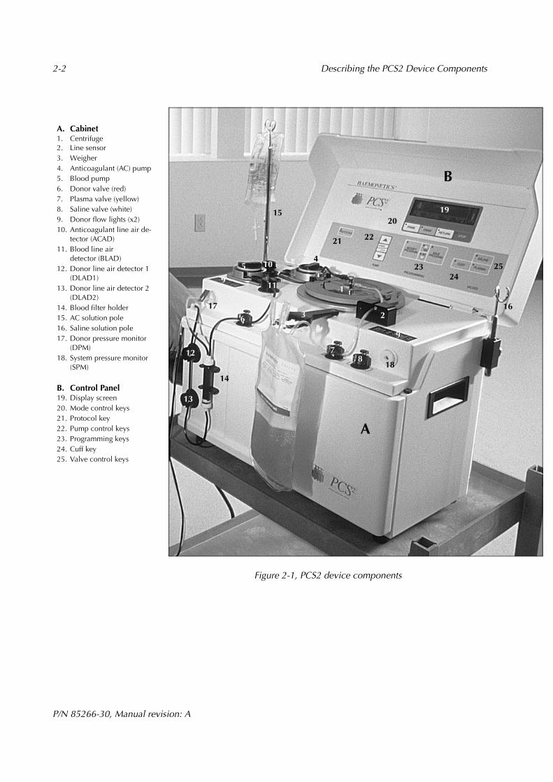
Figure 2-1, PCS2 device components
1920
9
2423
2221
25
12
14
17
13.54
6
11
3
18
7
1
8
2
B
9
13
16
10
A
15
A. Cabinet1. Centrifuge2. Line sensor3. Weigher4. Anticoagulant (AC) pump5. Blood pump6. Donor valve (red)7. Plasma valve (yellow)8. Saline valve (white)9. Donor flow lights (x2)10. Anticoagulant line air de-
tector (ACAD)11. Blood line air
detector (BLAD)12. Donor line air detector 1
(DLAD1)13. Donor line air detector 2
(DLAD2)14. Blood filter holder15. AC solution pole16. Saline solution pole17. Donor pressure monitor
(DPM)18. System pressure monitor
(SPM)
B. Control Panel19. Display screen20. Mode control keys21. Protocol key22. Pump control keys23. Programming keys24. Cuff key25. Valve control keys
Describing the PCS2 Device Components 2-3
P/N 85266-30, Manual revision: A
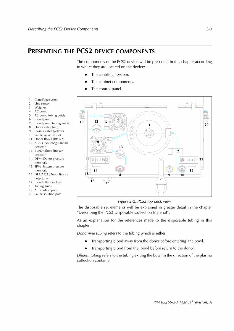
PRESENTING THE PCS2 DEVICE COMPONENTS
The components of the PCS2 device will be presented in this chapter accordingto where they are located on the device:
The centrifuge system.
The cabinet components.
The control panel.
Figure 2-2, PCS2 top deck view
The disposable set elements will be explained in greater detail in the chapter“Describing the PCS2 Disposable Collection Material”.
As an explanation for the references made to the disposable tubing in thischapter:
Donor-line tubing refers to the tubing which is either:
Transporting blood away from the donor before entering the bowl.
Transporting blood from the bowl before return to the donor.
Effluent tubing refers to the tubing exiting the bowl in the direction of the plasmacollection container.
1. Centrifuge system2. Line sensor3. Weigher4. AC pump5. AC pump tubing guide6. Blood pump7. Blood pump tubing guide8. Donor valve (red)9. Plasma valve (yellow)10. Saline valve (white)11. Donor flow lights (x2)12. ACAD (Anticoagulant air
detector).13. BLAD (Blood line air
detector).14. DPM (Donor pressure
monitor).15. SPM (System pressure
monitor).16. DLAD X 2 (Donor line air
detectors).17. Blood filter brackets18. Tubing guide19. AC solution pole20. Saline solution pole
12
18
12 5
13
14
11
83
9 1015
11
2
1
7
16
20
17
194
6

2-4 Describing the PCS2 Device Components
P/N 85266-30, Manual revision: A
DESCRIBING THE CENTRIFUGE SYSTEM
The centrifuge system of the PCS2 device is designed to hold a disposable bowlin which the blood components can be spun from a range of 3000 to 8000 revo-lutions per minute. This centrifugal force will separate anticoagulated wholeblood into its various components.
The PCS2 centrifuge system consists of:
A system-sealing mechanism.
The centrifuge well.
The centrifuge base.
Figure 2-3, PCS2 centrifuge system components
1. Split hinged lid2. Fluid detector3. Optical bowl sensor4. Locking knob5. Centrifuge well6. Centrifuge chuck7. Centrifuge base
3
1
2
4
6
5
7
1

Describing the PCS2 Device Components 2-5
P/N 85266-30, Manual revision: A
System-sealing mechanism
The PCS2 centrifuge contains a split, hinged lid (or cover) and a locking knob.These components “seal” the system by:
Securing the contact of the disposable bowl with the centrifuge base.
Isolating the spinning bowl from the operator.
Centrifuge cover
The centrifuge lid, referred to as the cover, has tabs located on the rimmedportion of each split side. The split halves are attached to the centrifuge rim by ahinge. As the halves of the lid are lowered to meet the rim, the tabs must be firmlypressed together in order to completely close the lid and provide a seal aroundthe stationary head of the disposable bowl.
The split halves of the lid are made from a durable, transparent material, allowingthe operator to observe changes in the bowl contents as the centrifuge spins.
Locking knob
The knob is positioned on the rim of the centrifuge well.
Once the lid has been fully closed, the knob requires a series of turns in a clock-wise direction to lock the centrifuge and thus completely seal the system.
To unlock the centrifuge, the operator should turn the knob in a counter-clock-wise direction until the split halves can be separated, then lifted, to open the lid.
Figure 2-4, PCS2 centrifuge cover

2-6 Describing the PCS2 Device Components
P/N 85266-30, Manual revision: A
Centrifuge well The PCS2 centrifuge well is designed with the following components:
Optical bowl sensor
There is an optical sensor located on the upper portion of the centrifuge well. Thesensor is aimed at the core of the bowl and will measure optical reflection as thevarious blood components pass in front of the optical beam.
Note: The interface between the optical sensor in the centrifuge well and thecontents of the bowl is often referred to as the “bowl optics readings” and will bediscussed further in the chapter “Understanding a PCS2 Collection Procedure”.
Fluid detector The PCS2 centrifuge well is equipped with an electronic fluid detection systemdesigned to detect the presence of liquid. The detector is mounted on the wall ofthe centrifuge well. The PCS2 safety system will automatically stop the centrifugeand the pumps if there is contact between liquid of any sort and the fluid detector.
Figure 2-5, PCS2 centrifuge well components
Centrifuge base The centrifuge base contains a centrifuge chuck designed to hold the disposablebowl in place during operation.When installing a bowl, the operator should exert a downward pressure on thehead of the bowl and ensure that the bowl is completely seated. A suction forcewill be created, between the base of the bowl and the chuck, to hold the bowl inplace. The bowl will be completely secured once the operator has locked thecentrifuge lid.To remove a bowl at the end of a procedure, the operator should open the centri-fuge lid and pull upward on the bowl.
Warning: The PCS2 device is equipped with a safety feature which will not al-low the centrifuge to spin if the lid has been improperly closed. It is unlikely thata properly installed centrifuge bowl will become unaligned as it spins. If the operator does notice anything unusual, under no circumstances, shouldthe operator attempt to open the centrifuge lid if the bowl is still spinning. Theoperator must ensure that the bowl has come to a complete stop before at-tempting to open the centrifuge for any reason.
1. Optical bowl sensor2. Fluid detector3. Centrifuge chuck
3
2 1

Describing the PCS2 Device Components 2-7
P/N 85266-30, Manual revision: A
DESCRIBING THE PCS2 CABINET COMPONENTS
Optical line Sensor
Located on the right side of the PCS2 top deck is the optical line sensor whichmonitors the blood components passing through the effluent tubing.
Caution The line sensor will not provide accurate readings if the optical lens itis obstructed in any way; thus the lens must be cleared of any extraneous sub-stances to ensure proper functioning of the system.
Weigher The weigher is the term used by Haemonetics to describe the PCS2 componentwhich measures in grams the contents of the plasma collection container(s)placed on the weigher arm. When the Draw key is pressed to initiate a proce-dure, the weigher will automatically tare, or deduct the weight of the emptyplasma collection container. Thus, the weight of the container will not beincluded in the weight displayed for the PCS2 procedure statistics.
To ensure optimal accuracy from the weigher during a collection procedure:
The weigher arm must be fully extended, positioned at a 90 degree an-gle to the PCS2 top deck, prior to the system self-tests.
The plasma collection container must hang freely without any contactwith the PCS2 cabinet.
Caution: The operator must be careful to not touch the weigher once the weightof the plasma container has been tared. This could affect the programmed targetplasma quantity and could result in an excessive collection of plasma during aDraw cycle. If the weigher senses a decrease in the weight during a Return cycle,an error message will be displayed.
To ensure that the weigher arm is within the appropriate calibration range, theoperator has the option to verify the weight displayed during the READY mode,prior to the first Draw cycle, as follows:
Remove the plasma container from the weigher arm.
Ensure that the weigher arm is fully extended at a 90 degree angle to thetop deck.
Hang a certified weight (not exceeding 1300 grams) from the emptyweigher arm.
Note the value displayed (and convert to grams if displayed in ml).
Replace the plasma container on the correctly positioned weigher arm.
The measurement of the weight displayed in grams should be within 1% of thecertified weight.

2-8 Describing the PCS2 Device Components
P/N 85266-30, Manual revision: A
Pumps Located on the left side of the PCS2 top deck are two pumps which use peristalticmovements to displace fluids through the disposable-set tubing.
Figure 2-6, PCS2 pump rotor
Anticoagulant pump
The AC pump, designated by the color blue, moves AC solution between the ACsolution bag and the needle connector of the donor line tubing.
Blood pump
The Blood pump, designated by the color red, moves fluids between the donorand the centrifuge bowl.
The pumps function during the different modes of PCS2 operation as follows:
When loading the disposable tubing, the AC pump and the Blood pumpturn simultaneously to thread the tubing onto the pump rotors.
During the PRIME mode, the AC pump and the Blood pump turn simul-taneously to provide the inlet side of the donor line tubing with AC so-lution.
During the DRAW mode, the AC pump and the Blood pump turn simul-taneously. The Blood pump pulls anticoagulated whole blood throughthe blood filter of the disposable set into the centrifuge bowl.
During the RETURN mode, the Blood pump pulls the remaining bloodcomponents from the centrifuge bowl and re-infuses them to the donor.
Note: The two pumps will rotate at different speeds during the PCS2 modes ofoperation, depending on the AC/Blood pump ratio procedure parameter setting.
Pump tubing guide
Next to each of the PCS2 pumps is a tubing guide. It will secure the disposabletubing during pump autoloading, as well as during the collection procedure.

Describing the PCS2 Device Components 2-9
P/N 85266-30, Manual revision: A
Valves There are three valves located on the PCS2 top deck which automatically controlthe flow of fluids through the disposable set tubing. The valves are color-codedaccording to their specific functions.
The PCS2 safety system will control the valves during the self-diagnostic tests.Once the operator has selected a collection procedure, the appropriate valveswill automatically open, in preparation for loading the disposable set tubing. Ifthe disposable tubing needs an adjustment during a procedure, it is possible toopen a valve manually by pressing the valve lever located at the top of each valve.
Warning: Any manual adjustment to a valve should be attempted only if thePCS2 device is POWERED-OFF, in the READY mode, or when the pumps arestopped. At any other time, the PCS2 safety system will be alerted and will in-terrupt the procedure. Manipulating a valve could lead to flow problems, andeventually cause hemolysis.
Donor valve (red)
The donor valve is located the furthest to the left on the PCS2 top deck.
During the DRAW mode it remains open so that anticoagulated wholeblood can flow from the donor into the centrifuge bowl.
During the RETURN mode it remains open so that components remain-ing in the disposable tubing and centrifuge bowl can be returned to thedonor.
Plasma valve (yellow)
The plasma valve is located between the donor valve and the saline valve.
During the DRAW mode it remains open to direct plasma and air flow-ing through the effluent tubing into the plasma collection container.
During the RETURN mode it remains open, except for a brief periodwhen the effluent line is cleared during a standard bowl procedure. It is closed during automatic saline compensation to the donor.
Saline valve (white)
The saline valve is located the furthest to the right on the PCS2 top deck. It willwill be used to direct saline solution through the tubing, with the exception of amulti-bag plasma collection procedure.
During the DRAW mode it will be closed.
During the RETURN mode it will be open to permit the passage of fluidthrough the effluent tubing.
Note: When the selected PCS2 procedure uses more than one plasma collectionbags, plasma will be distributed equally between the bags, using the plasma valveto route half of the plasma being collected, and the saline valve to route the otherhalf. The two valves will not be open at the same time during DRAW, thereforeautomatic saline compensation is not a possibility when more than one plasmabag is used.

2-10 Describing the PCS2 Device Components
P/N 85266-30, Manual revision: A
Donor flow lights These color-coded lights, located on both sides of the PCS2 top deck, indicatedonor blood-flow status during the DRAW and RETURN modes. They arecontained in a rectangular panel on the PCS2 top deck.
Figure 2-7, PCS2 donor flow lights
DRAW mode
The GREEN light indicates that donor blood flow is adequate for theblood pump to maintain an adequate speed.
The YELLOW light indicates that donor flow is decreasing to a rate of lessthan 2/3 of what is required to maintain an adequate speed.
The RED light indicates that blood is not flowing adequately or not flow-ing at all from the donor.
If the RED flow light is lit, the Blood pump will automatically stop. The centrifugewill continue to spin to ensure continued separation of the collected bloodcomponents. When donor blood flow is restored, the pump will automaticallyrestart.
RETURN mode
The YELLOW light indicates that the non-selected blood componentsare being returned to the donor. No other donor light will be visible atthis time.
Note: If any of the DRAW mode lights are lit, the donor can promote blood flowby clenching and relaxing the hand below the needle site. When the RETURNyellow light is lit, the donor should NOT do this, because the blood componentsin the bowl are being returned. The operator should instruct the donor to observethe differences in the lights and act accordingly.
DRAW modeNormal flow / Green
Low flow / Yellow
No flow / Red
RETURN modeReturn flow / Yellow
Describing the PCS2 Device Components 2-11
P/N 85266-30, Manual revision: A
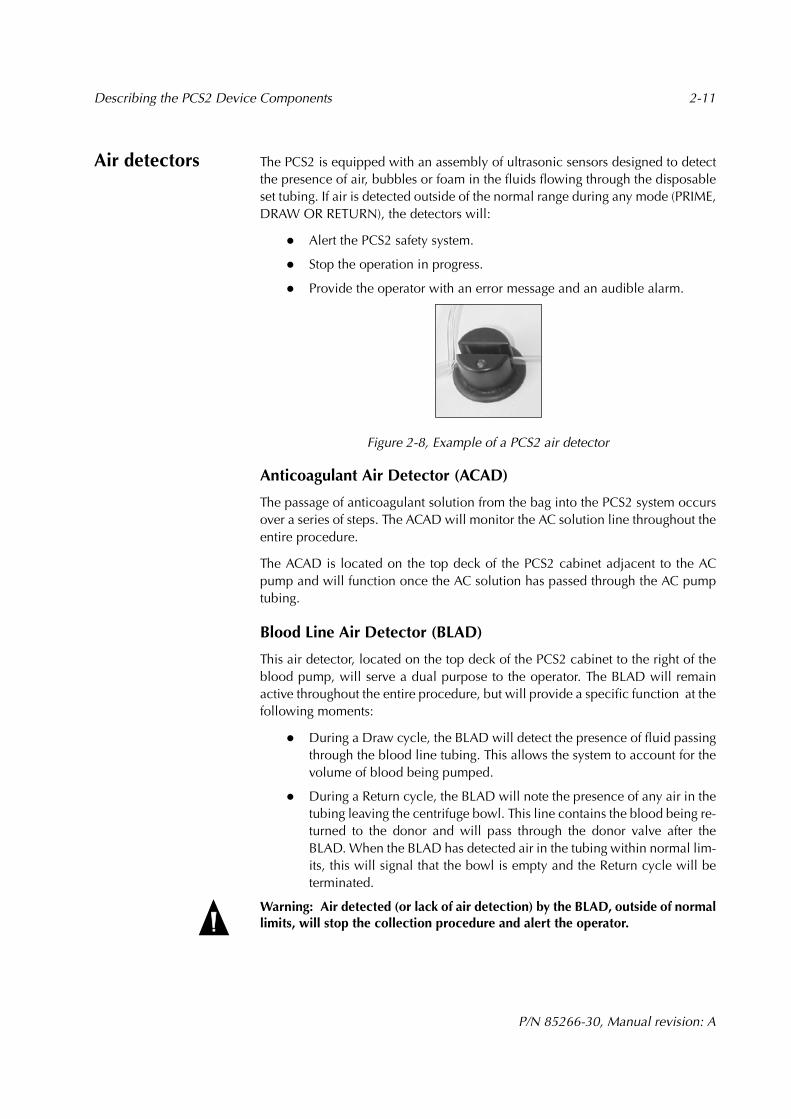
Air detectors The PCS2 is equipped with an assembly of ultrasonic sensors designed to detectthe presence of air, bubbles or foam in the fluids flowing through the disposableset tubing. If air is detected outside of the normal range during any mode (PRIME,DRAW OR RETURN), the detectors will:
Alert the PCS2 safety system.
Stop the operation in progress.
Provide the operator with an error message and an audible alarm.
Figure 2-8, Example of a PCS2 air detector
Anticoagulant Air Detector (ACAD)
The passage of anticoagulant solution from the bag into the PCS2 system occursover a series of steps. The ACAD will monitor the AC solution line throughout theentire procedure.
The ACAD is located on the top deck of the PCS2 cabinet adjacent to the ACpump and will function once the AC solution has passed through the AC pumptubing.
Blood Line Air Detector (BLAD)
This air detector, located on the top deck of the PCS2 cabinet to the right of theblood pump, will serve a dual purpose to the operator. The BLAD will remainactive throughout the entire procedure, but will provide a specific function at thefollowing moments:
During a Draw cycle, the BLAD will detect the presence of fluid passingthrough the blood line tubing. This allows the system to account for thevolume of blood being pumped.
During a Return cycle, the BLAD will note the presence of any air in thetubing leaving the centrifuge bowl. This line contains the blood being re-turned to the donor and will pass through the donor valve after theBLAD. When the BLAD has detected air in the tubing within normal lim-its, this will signal that the bowl is empty and the Return cycle will beterminated.
Warning: Air detected (or lack of air detection) by the BLAD, outside of normallimits, will stop the collection procedure and alert the operator.

2-12 Describing the PCS2 Device Components
P/N 85266-30, Manual revision: A
Donor line air detectors (DLAD1 and DLAD2)
The two donor line air detectors are located on the left side of the PCS2 frontpanel; the DLAD1 is located above the DLAD2. Both air detectors monitor thedonor line between the donor and the disposable set blood filter as follows:
During the PRIME mode, the pumps draw AC solution into the donorline up to the DLAD. When the DLAD note fluid (or an absence of air),the detectors signal to PCS2 software that the line has been primed withanticoagulant solution and is prepared for the Draw cycle.
During the DRAW mode, the DLAD will monitor the tubing containinganticoagulated whole blood and alert the operator if any air has been in-troduced into the system.
During the RETURN mode, the DLAD will monitor the donor line as itcarries blood components being returned to the donor. The DLAD mon-itor the line for any air which may have passed into the system undetec-ted (probability very low) by the BLAD.
Warning: In the case of any air detection alarm, the operator must respond im-mediately, note the source and take appropriate action. Further information isprovided in the chapter “Troubleshooting for a PCS2 Procedure.”During a Return cycle, if either the DLAD1 and/or DLAD2 produce an air de-tection alarm, this could indicate a failure of the BLAD. The operator shouldcarefully note the source of air detected; no blood should be sent to the donoruntil all air bubbles have been removed from the line.
Haemonetics recommends the following operator actions to remove any airbubbles detected in the tubing between the BLAD, DLAD1 and the DLAD2:
Press the Draw key until blood enters the bowl, to send any air bubblesto the bowl.
Continue with a Return cycle only after any air bubbles have been removed.
Figure 2-9, PCS2 front/side view
1. DLAD12. DLAD23. Blood filter brackets4. AC solution pole5. DPM6. SPM 1
2
3
5
64
Describing the PCS2 Device Components 2-13
P/N 85266-30, Manual revision: A
Pressure monitors
The electronically controlled pressure monitors function with the correlatingfilter on the disposable set to measure pressure in the disposable tubing. Thepressure monitors provide feedback to the system about the flow of bloodcomponents. The PCS2 programming will automatically regulate the speed of thepumps based on this information.
Donor pressure monitor (DPM)
The DPM, located on the left side of the PCS2 top deck, measures pressure in thedonor line tubing. The information is depicted on the display screen using a bargraph. The bar graph is visible on the screen when donor pressure is adequate tomaintain the programmed pump speed. The bar graph will not be visible if donor-line pressure is below what is required to maintain the programmed pump speed.
Variations will exist in the readings, depending on the operating mode. The PCS2software is programmed to detect a range of normal values. If a pressure readingvaries outside of this range, the PCS2 safety system will stop the pumps andprovide an explanatory screen message, as well as an intermittent alarm.
Caution: Once the DPM and the disposable set filter have been connected, thesystem is ready to measure the pressure in the donor line. This connection shouldnot be disrupted at any point. In the event of a power failure, the operator shouldrefer to the chapter “Troubleshooting During a PCS2 Procedure” for details abouthandling the DPM and the donor line tubing. The DPM tubing must be clamped before removing the filter to ensure that the procedure can be recovered.
DRAW mode
The pressure readings will vary as blood is drawn from the donor. If a significantpressure decrease is detected and the DPM readings drop below a programmedvalue, the pump speed will automatically decrease until a sufficient pressureincrease is measured.
If the donor-line pressure is measured as insufficient, the pumps will stop, the NOFLOW indicator lights will be visible and an explanatory screen message willappear with an alarm. Once pressure is measured to be within normal operatingrange, the pumps will resume the programmed speed.
RETURN mode
The pressure readings will vary as blood is returned to the donor. If a significantpressure increase is detected, and the pressure readings rise above a programmedvalue, the pump speed will automatically decrease until a sufficient pressurechange is measured. If pressure readings remain high, the Blood pump will stop,and an explanatory screen message will appear with an alarm.
When pressure is measured to be within the normal operating range, the pumpswill resume operation until reaching the programmed pump speed.
2-14 Describing the PCS2 Device Components
P/N 85266-30, Manual revision: A
Warning: The operator must remain aware of the fact that a high pressurewarning can indicate a possible flow obstruction and could cause red blood cellhemolysis, and/or damage the vein. Corrective action is necessary and the operator should consult the chapter“Troubleshooting During a PCS2 Procedure”, as well as the chapter “EnsuringSafety and Quality for a PCS2 Procedure“ for further information.
System pressure monitor (SPM) (optional)
The SPM, located on the right side of the PCS2 top deck, measures pressure in theeffluent tubing. This measurement verifies that the sterile seal, between the headand the body of the centrifuge bowl, remains intact.
If the SPM detects that pressure in the system increases or decreases abnormally,the PCS2 safety system will stop the pumps and provide an explanatory messagewith an alarm. Centrifuge function will remain unaffected.
Blood filter holder
Located on the left side of the PCS2 front panel are two brackets designed tosecure the blood filter chamber of the disposable set during the procedure.
Solution-bag poles (2)
Located on either side of the PCS2 cabinet is a height-adjustable pole. Thesepoles are used to hang the solution bags during the procedure. The left poleshould be used to hang the anticoagulant solution, whereas the right pole shouldbe used to hang the saline solution (if selected).
There is a knob located on the base of each pole. Pulling the knob outward willdisengage the contact pin from the pole and allow the operator to extend orretract the pole.

Describing the PCS2 Device Components 2-15
P/N 85266-30, Manual revision: A
Power entry module
The power entry module is located on the left panel of the device. Externally, themodule consists of an ON/OFF power switch and a power-input receptacle forthe power cord. Internally, the module contains the fuse panel. It will interruptpower supply to the system in the event of an electrical current surcharge.
The design of the power entry module also provides a filter-effect for the PCS2device against the effects of a power surge
In the case of an emergency, the ON/OFF switch can be used to stop all devicefunction.
Figure 2-10, Power entry module (PEM)
Power cord The power cord provided is designed to connect the PCS2 device with anexternal power source via the power-input receptacle, located on the power-entry module on the left side panel.
Pressure cuff The tourniquet-style pressure cuff is used to maintain an optimal venous blood-flow from the donor during specific phases of the collection procedure. The cuffshould be attached to the PCS2 cuff connector located on the PCS2 rear panel.
Biohazard waste bag
The biohazard waste bag is designed to collect any biologically contaminatedmaterial from the centrifuge well in the rare case of a spill or leak. Two biohazardwaste bags are supplied with the delivery of each PCS2 device.
A bag must be attached at all times to the centrifuge drain tube, located at therear of the device. The bag must hang freely, with the clamp open, visible to theoperator.
Warning: The biohazard waste bags are not to be used to collect or store aph-eresis products. When a bag contains evacuated waste products, it must beclamped, removed and properly disposed of, according to the local policies con-cerning biologically contaminated material. A new bag must be placed beforeresuming operation.
ON/OFF power switch
Power input receptacle
2-16 Describing the PCS2 Device Components
P/N 85266-30, Manual revision: A
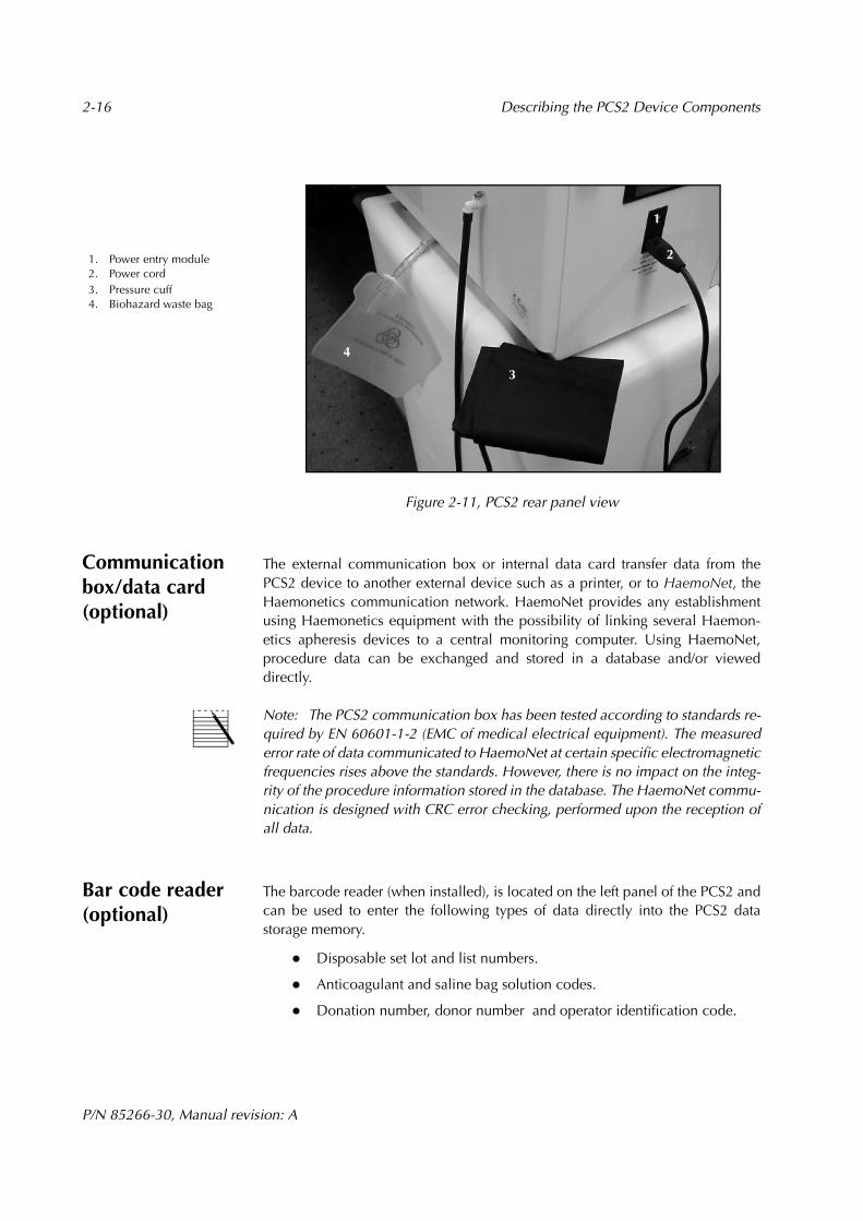
Figure 2-11, PCS2 rear panel view
Communication box/data card (optional)
The external communication box or internal data card transfer data from thePCS2 device to another external device such as a printer, or to HaemoNet, theHaemonetics communication network. HaemoNet provides any establishmentusing Haemonetics equipment with the possibility of linking several Haemon-etics apheresis devices to a central monitoring computer. Using HaemoNet,procedure data can be exchanged and stored in a database and/or vieweddirectly.
Note: The PCS2 communication box has been tested according to standards re-quired by EN 60601-1-2 (EMC of medical electrical equipment). The measurederror rate of data communicated to HaemoNet at certain specific electromagneticfrequencies rises above the standards. However, there is no impact on the integ-rity of the procedure information stored in the database. The HaemoNet commu-nication is designed with CRC error checking, performed upon the reception ofall data.
Bar code reader (optional)
The barcode reader (when installed), is located on the left panel of the PCS2 andcan be used to enter the following types of data directly into the PCS2 datastorage memory.
Disposable set lot and list numbers.
Anticoagulant and saline bag solution codes.
Donation number, donor number and operator identification code.
1. Power entry module2. Power cord3. Pressure cuff4. Biohazard waste bag
2
3
4
1

Describing the PCS2 Device Components 2-17
P/N 85266-30, Manual revision: A
DESCRIBING THE PCS2 CONTROL PANEL
The control panel, located on the inside of the hinged PCS2 cabinet cover,consists of a display screen and a keypad comprised of several groups of keys.The control panel allows the operator to interact with the system by enteringappropriate data and observing feedback. There is a protective plastic coating onthe keypad, which allows for efficient cleaning and disinfecting.
Figure 2-12, The PCS2 control panel components
Display screen The control panel display screen will provide data related to procedure status, aswell as donor status, throughout the entire procedure. The information will bedisplayed in specific areas as follows:
Figure 2-13, Example of a PCS2 display screen message
Message area
The center portion of the screen display will provide textual information aboutthe current state (or mode) of operation, while the actual cycle in progress will be(visible in the upper right corner).
1. Display screen 2. Mode control keys3. Protocol key4. Pump control keys5. Programming keys6. Cuff key7. Valve control keys
1
3
2
4
65
7
1. Active state message.2. Procedure acronym.3. Operating state icon.4. Procedure statistics area.5. DPM bar graph reading.
ACRONYM 0READY
Pump Plasma NaCl Cuf VPro0 30/600 0 0 0 DPM
3
4
2
15

2-18 Describing the PCS2 Device Components
P/N 85266-30, Manual revision: A
Procedure acronym
The upper left portion of the display screen will contain the acronym selected todescribe the type of procedure in progress.
Display screen icons
These symbols, located on the upper left side of the display screen, provide apictorial representation of the operating state, or mode, in progress.
DPM bar graph
This is a visual representation of the pressure reading in the donor-line tubing, asit measured by the donor pressure monitor. The DPM bar graph (when visible) islocated on the right side of the screen. The contrast between filled and non-filledarea in the column will vary to depict the fluctuations in the DPM readings.
Table 2-1: PCS2 display screen icons
Display screen icon
Explanation Operating state/mode
Displayed during AC solution priming sequence. PRIME
Displayed when the device in a non-active state, or ready for an operator command.
READY
Displayed as donor blood is being drawn into the centrifuge bowl.
DRAW
Displayed as blood components/fluids are being returned to the donor.
RETURN
Displayed briefly at the end of the procedure, prior to the completed procedure statistics displayed.
PROCEDURE COMPLETE
Displayed when the centrifuge is stopping.
AC
STOP
Describing the PCS2 Device Components 2-19
P/N 85266-30, Manual revision: A
Procedure statistics area
The lower portion of the screen communicates data to the operator concerningspecific measurements and calculations made by the system during a PCS2collection procedure. These statistics are updated throughout a procedure andconcern the following component functions:
Blood pump speed during the DRAW and RETURN modes.
Amount of the plasma contained in the collection container.
Cuff pressure registered for the donor (mmHg).
Saline solution volume infused (if selected) during the procedure.
Volume processed (ml).
Mode control keys
These keys, located directly below the PCS2 display screen, are used to regulatethe operating state (or mode) of a PCS2 collection procedure.
PRIME key
This key is used to initiate the PRIME mode. The PRIME mode will bring antico-agulant solution from the anticoagulant line tubing into the donor- line tubing.
DRAW key
This key is used to initiate the DRAW mode. The DRAW mode will move anti-coagulated whole blood from the donor through the donor-line tubing into thecentrifuge bowl, where plasmapheresis will be initiated.
RETURN key
This key is used to initiate, or resume, the RETURN mode. During automatedprocedure functioning, a Return cycle is automatically initiated. However thiskey can be used to provide an early return of the bowl contents to the donor, ifnecessary.
STOP key
This key is used to immediately stop the centrifuge and pumps.
Caution: If the STOP KEY has been used during a Draw cycle, the bowl contentsshould be returned to the donor before resuming the collection procedure. Stopping the procedure during the DRAW mode could affect the separation of theblood components in the bowl. This could eventually interfere with the qualityof the final collection product (and/or the collection procedure).
Protocol key This key is used to select certain PCS2 procedures and any options. Further infor-mation in provided in the chapter “Performing a PCS2 Collection Procedure”.
2-20 Describing the PCS2 Device Components
P/N 85266-30, Manual revision: A
Pump control keys
These keys can be used by the operator to manually change the preset pumpspeed during a collection procedure.
Pump arrow keys
These keys can be used to temporarily modify the default parameter settings byrespectively increasing (arrow up) or decreasing (arrow down) the speed in whichthe pumps will rotate. The adjustment should be made based on individual donorneeds during a specific collection procedure.
Caution: During a Draw cycle, the operator should observe the DPM bar graphand flow indicator lights in order to correctly asses for low donor blood flow.However, before using the arrow keys to adjust for low donor flow, it is importantthat the operator allow the PCS2 device to first reach the preset target pumpspeed.
Warning: During a Return cycle, if the pump speed is manually decreased, theoperator must carefully monitor the venipuncture site, to avoid possible conse-quences of an infiltrated vein for the donor, such as hematoma.
Pump start/stop key
This key can be used to either stop the pumps, or re-start the pumps if stopped bythe operator.
Caution: If the pumps have been stopped using this key, and remain stopped forlonger than two to three minutes during a Draw cycle, the bowl may becomeover-packed with red cells because the centrifuge will continue to spin. This cancreate a potential flow problem during the Return cycle. In this case, the operatorshould return the bowl contents to the donor before proceeding with a Draw cycle.
Programming keys
This section of the PCS2 keypad consists of four keys which enable the operatorto modify specific PCS2 procedure parameters. Certain system operating param-eters have been selected by Haemonetics as default values. These parametersprovide optimal results in PCS2 plasmapheresis procedures with the averagedonor, as well as for average collection requirements.
However, it is possible to alter and subsequently retain the altered parameters forspecific collection requirements. Once the program parameters have beenconsulted and/or modified, the operator can return to the screen depicting thecurrent mode of operation without interruption to the collection procedure.Further information is provided in the chapter “Understanding a PCS2 CollectionProcedure.”

Describing the PCS2 Device Components 2-21
P/N 85266-30, Manual revision: A
Modify Program key
This key is used to access and scroll the list of procedure parameters; it can bepressed during any of the operating modes. Each time that this key is pressed, adifferent program parameter will be displayed on the screen, along with thecurrent setting for that parameter. To modify the parameter setting, the operatorshould use the Yes/No arrow keys.
YES/NO Arrow keys
These keys have a dual function:
Provide a response to a question-prompt from the PCS2 software.
Modify the parameter setting displayed on the screen.
To modify a displayed parameter value, the operator should:
Press the Yes key (arrow up) to increase the value.
Press the No key (arrow down) to decrease the value.
Save Program key
The operator can use this key to retain each modified value in the PCS2 memory.If this key is pressed after a modification, the selected value will become the newsystem default value until any further modification is made during subsequentPCS2 collection procedures.
Cuff key This key is located on the keypad next to the saline and plasma valve keys.During procedure operation, the cuff will automatically inflate during the DRAWmode and deflate during the RETURN mode. The cuff cannot be inflated duringthe RETURN mode. The operator can use the key to manually control the pres-sure cuff:
Prior to a procedure when performing the venipuncture
During the READY or DRAW modes, to modify cuff pressure.
Valve control keys
These keys can be used to manually control what would normally be the auto-matic control of a valve, as in the case of manual saline compensation before thefinal Return cycle. When a valve control key has been pressed, the key will be lit,indicating that the valve is open. When it is re-pressed, the valve will close.
Saline key
This key can be used to manually control the saline (white) valve.
Plasma key
This key can be used to manually control the plasma (yellow) valve.

P/N 85266-30, Manual revision: A
Chapter 3
Maintaining the PCS2 Equipment
CLEANING PROCEDURES . . . . . . . . . . . . . . . . . . . . . . . . . . . . . . . . . . . . . 3-2Cabinet, control panel and valves. . . . . . . . . . . . . . . . . . . . . . . . . . . . . 3-2Pressure monitors . . . . . . . . . . . . . . . . . . . . . . . . . . . . . . . . . . . . . . . . . 3-3Air detectors . . . . . . . . . . . . . . . . . . . . . . . . . . . . . . . . . . . . . . . . . . . . . 3-3Optical sensors. . . . . . . . . . . . . . . . . . . . . . . . . . . . . . . . . . . . . . . . . . . 3-3Fluid detector . . . . . . . . . . . . . . . . . . . . . . . . . . . . . . . . . . . . . . . . . . . . 3-4Centrifuge components. . . . . . . . . . . . . . . . . . . . . . . . . . . . . . . . . . . . . 3-4Pumps . . . . . . . . . . . . . . . . . . . . . . . . . . . . . . . . . . . . . . . . . . . . . . . . . 3-5Filter screens . . . . . . . . . . . . . . . . . . . . . . . . . . . . . . . . . . . . . . . . . . . . 3-5Barcode reader . . . . . . . . . . . . . . . . . . . . . . . . . . . . . . . . . . . . . . . . . . . 3-5
CUSTOMER SERVICE . . . . . . . . . . . . . . . . . . . . . . . . . . . . . . . . . . . . . . . . . 3-6Clinical training . . . . . . . . . . . . . . . . . . . . . . . . . . . . . . . . . . . . . . . . . . 3-6Field service . . . . . . . . . . . . . . . . . . . . . . . . . . . . . . . . . . . . . . . . . . . . . 3-6Returned Goods Authorization system . . . . . . . . . . . . . . . . . . . . . . . . . 3-6
HAEMONETICS® CLEANING AND MAINTENANCE RECORD . . . . . . . . . 3-8

3-2 Maintaining the PCS2 Equipment
P/N 85266-30, Manual revision: A
CLEANING PROCEDURES
The PCS2 device has been designed to require minimal maintenance for theoperator. To maintain the precision function of the PCS2 device, the operatorneeds to primarily perform routine cleaning procedures of certain key compo-nents. A record of routine cleaning should be kept along with any routine orpreventive service maintenance performed by a Haemonetics representative,and a form is provided at the end of this chapter.
The frequency of cleaning each individual PCS2 device will depend on thenumber of procedures performed. Special cleaning needs may arise and shouldbe dealt with promptly. Haemonetics recommends the following routinecleaning schedule for each PCS2 device, based on an average of three collectionprocedures per day, or approximately sixty per month.
Daily: Clean the exterior surfaces as well as the pressure monitors.
Weekly: Clean the air detectors, the optical sensors (line sensor and op-tical bowl sensor), the fluid detector and the inside of the centrifuge well.
Monthly: Clean the pump rotors and the pump wells.
Quarterly: Clean the filter screens.
Warning: To eliminate the potential danger of electrical shock, the operatormust clean the PCS2 device only when it is disconnected from an external pow-er source.
The following list describes the basic material required for routine cleaning.
Disinfectant cleaning solution, specific for blood born pathogens andcompatible for cleaning Lexan® plastic.
Warm water.
70% Isopropyl alcohol.
Lint-free gauze or cloth (for cleaning and drying).
Cotton swabs.
Protective gloves.
Hexagonal-head wrench #10 (provided with the device).
Silicon lubricant (used for the O-ring gasket of the centrifuge chuck).
Phillips-head screwdriver.
Cabinet, control panel and valves
The exterior cabinet, keypad, display screen and valves should be wiped daily, aswell as following any spill, using an appropriate cleaning solution.
Caution: Certain cleaning solutions can degrade the Lexan plastic parts of thePCS2 valves and only compatible cleaning solutions should be used.

Maintaining the PCS2 Equipment 3-3
P/N 85266-30, Manual revision: A
Pressure monitors
The pressure monitors (DPM/SPM) should be cleaned daily in the followingmanner:
Depress and hold the white ring as if installing the disposable filter.
Wipe the silver rod thoroughly, using a circular motion and warm water.
Dry the rod and release the pressure on the ring.
Caution: It is very important to use only water on the pressure monitor rod. Alcohol or cleaning solution residue could cause a reaction with the plastic ma-terial of the corresponding disposable set filter and affect the function of the filter.
Air detectors The DLAD1, DLAD2, and BLAD are designed with a groove to hold the dispos-able tubing. The contents of the tubing are monitored by the sensors which arelocated internally on either side of this groove. If a procedure is interrupted dueto an air detector alarm, the operator should remove the tubing and clean thegroove before continuing the collection procedure.
The operator should use only warm water and lint-free gauze to clean and dryinside of the tubing grove. The groove should be kept free of any particles, suchas powder residue from disposable gloves, since this could lead to an erroneousdetection of air.
Caution: Alcohol may cause the plastic housing to degrade and must not be usedto clean the air detectors.
Optical sensors The lenses of the optical sensors must be kept completely free of particles ordebris which could produce inaccurate readings and influence the PCS2 deviceperformance. The operator should use only water and lint-free gauze to clean anddry the lenses.
Caution: If cleaning solution should come into contact with the optical sensorlenses, the lenses should be cleaned immediately with lint-free gauze and warmwater, then thoroughly dried. Dried cleaning solution can leave an opaque filmon the lens.
Line sensor
The line sensor, located on the PCS2 top deck, contains two very small lenseswhich are centered on either side of the disposable tubing groove. The operatorshould carefully pass the gauze through this groove to clean and dry the lenses.
Optical bowl sensor
The optical bowl sensor lens is located in the upper portion of the centrifuge well.The operator should ensure that no spots remain on the lens cover after it hasbeen cleaned and dried.

3-4 Maintaining the PCS2 Equipment
P/N 85266-30, Manual revision: A
Fluid detector The fluid detector is located inside of the centrifuge well. The surface of thedetector should be cleaned using a cotton swab moistened with 70% alcohol.
Centrifuge components
Except for the optical sensor and fluid detector, the other centrifuge componentscan be wiped routinely using the cleaning solution and a lint-free cloth. Thisincludes the centrifuge well, chuck, hinged lid and locking knob.
Haemonetics Technical Services provides silicon lubricant for the O-ring gasket,located at the base of the centrifuge chuck. After a major cleaning, the operatorshould apply a small amount of the lubricant to the gasket to prevent it fromcracking. It is not necessary to remove the gasket when applying the lubricant.
If the case of a fluid spill, the operator should:
Power off the device and disconnect it from the external power sourcebefore cleaning.
Ensure that the biohazard waste bag is attached to the drain tube andhangs freely.
Wipe the centrifuge lid with cleaning solution.
Clean the centrifuge chuck and well (avoiding the optical sensor lens)using the disinfectant solution and a lint-free cloth until all traces ofblood components are removed.
Lubricate the O-ring gasket with a small amount of the silicon lubricant.
Haemonetics recommends that the operator wear protective gloves to avoiddirect contact with the cleaning solution and/or any spilled blood which may bepresent.
In the case of a larger spill, fluid and/or blood may be evacuated into thebiohazard waste bag. The operator should complete the following additionalsteps and contact the local Haemonetics representative for further instructionsbefore using the device:
Irrigate the centrifuge drain holes with cleaning solution, until the draintube is rinsed clear of the spilled material.
Remove the bag and replace it with a new bag.
Dispose of the used waste bag according to local established policiesconcerning the disposal of biohazard waste.
Note: A 50 ml syringe of attached to a 20 cm section of disposable tubing placedin the drain holes can be used for irrigation. The biohazard waste bag should bemonitored to avoid overfilling.
Warning: An authorized Haemonetics technician should perform a leakagecurrent control after any major fluid spill involving the PCS2 device. Leakagecurrent represents a primary indication of electrical shock hazard and shouldbe checked according to guidelines as described in local standard operating pro-cedures.
Maintaining the PCS2 Equipment 3-5
P/N 85266-30, Manual revision: A
Pumps The pump rotors should be removed from the well with the hexagonal headwrench. Debris should be removed from the rotors and the pump wells on aroutine basis, as well as after any spills to contribute to efficient PCS2 operation.
For routine cleaning, the operator should:
Remove the pump rotor from the housing, using the hexagonal headwrench to remove the pump screw.
Wipe the rotor and remove all debris from the rollers, using warm waterand lint-free cloth or gauze.
Dry with lint free cloth (or compressed air, if available).
Clean and dry the pump well using the same method.
Ensure that all of the rollers spin freely and replace the pump rotor in thewell, aligning the cross pin in the rotor with the pump shaft.
Replace and tighten the hexagonal head screw.
In the case of a fluid spill, the same cleaning method should be followed;however, disinfectant cleaning solution should be used, followed by a clear waterrinse. The pump head should not be immersed in water.
Filter screens The PCS2 device is equipped with filter screens on the bottom of the cabinet,which eliminate dust from incoming cool air. The filters should be cleanedroutinely, especially if dust becomes visible on the screens.
To clean the filters, the operator should:
Remove the retainer plates using a Phillips-head screwdriver.
Remove the filter screens from the panel.
Rinse the screens under running water - DO NOT use any cleaningagents.
Gently squeeze the screens to remove excess water.
Place the screens on a clean, dry cloth and allow to dry completely.
Reinsert the screens into the panel, ensuring that all openings are com-pletely covered by the filter.
Replace the retainer plates and tighten the screws.
Warning: To avoid electrical shock, the filter screen should be completely drybefore it is reinstalled on the PCS2 cabinet.
Barcode reader The barcode reader window should be wiped using a lint-free cloth or gauze andwater, then dried. It should be cleaned whenever there is an accumulation of dustor spilled fluid. For optimal cleaning, the operator should remove the protectoraround the window and replace it once the window has been cleaned.

CUSTOMER SERVICE
Clinical training Haemonetics employs a staff of Clinical Specialists to provide training for apher-esis personnel concerning the use of the PCS2 equipment. The local Haemon-etics representative will schedule staff training upon delivery of PCS2 equipmentand should be contacted to organize further instruction when needed.
Field service Haemonetics maintains a worldwide network of company-trained service repre-sentatives responsible for responding to technical needs concerning equipment.These technical specialists are available to diagnose and repair any malfunctions,as well as provide routine annual or semi-annual maintenance of the apheresisequipment, including leakage current tests. If service beyond the routine mainte-nance and cleaning described in this manual is required, the local Haemoneticsrepresentative should be contacted to provide specific instruction.
Returned Goods Authorization system
Haemonetics seeks to provide the apheresis customer with equipment and mate-rial which respects the highest established standards of quality in design andmanufacturing. If for any reason merchandise must be returned to the company,the customer should refer to the Haemonetics Returned Goods Authorization(RGA) system procedure to ensure proper handling and subsequent analysis ofthe material.
The customer should contact the local Haemonetics Representative (or theHaemonetics Customer Service Department) and provide the following informa-tion:
Product list number, lot number and manufacture date.
Number of articles to be returned.
Description of defect.
Number of parcels being shipped.
The Haemonetics Representative may ask for additional details, depending onthe nature of the problem. The customer should be prepared to provide a thor-ough description of the problem encountered, as well as the product informationlisted above.
If a contaminated disposable set must be returned by courier services, theHaemonetics Representative may provide specific instructions concerning prep-aration for shipping blood-contaminated products. In addition to the Haemon-etics guidelines, the consumer should strictly follow the local standard operatingprocedure related to the shipment of blood-contaminated materials and thusminimize any potential health hazards involved.
Maintaining the PCS2 Equipment 3-7
P/N 85266-30, Manual revision: A
In some cases, it may be necessary to dispose of the contaminated goods afterreporting the problem to the Haemonetics representative. This should be doneaccording to the locally established guidelines pertaining to the disposal ofbiologically contaminated material.
Warning: Haemonetics products must be properly cleaned and packed prior totheir return. It remains an important responsibility of the customer to reducethis serious potential health hazard, by being aware of the risks involved in theshipping, handling and testing of this material.

HA
EM
ON
ET
ICS®
Cle
anin
g an
d M
aint
enan
ce R
ecor
d
Dev
ice
seri
al n
umbe
r: ..
......
......
......
......
......
......
......
......
.....
Year
of o
pera
tion
: .....
......
......
......
......
......
......
......
......
......
..
Ann
ual p
reve
ntiv
e m
aint
enan
ce s
houl
d be
sch
edul
ed b
y a
supe
rvis
or w
hen
appr
opri
ate
and
perf
orm
ed b
y a
Hae
mon
etic
s se
rvic
e re
pres
enta
tive
or
a qu
alifi
ed e
ngin
eer.
Ann
ual m
aint
enan
ce p
erfo
rmed
by:
......
......
......
......
......
......
......
......
......
Dat
e pe
rfor
med
: ....
......
......
......
......
......
......
...
Rev
iew
ed b
y: .
......
......
......
......
......
......
......
......
......
......
......
......
......
......
..D
ate/
init
ials
: .....
......
......
......
......
......
......
......
....
Act
ion
Cle
an c
abin
et, c
ontr
ol p
anel
an
d va
lves
.
Cle
an a
ir d
etec
tors
.
Cle
an p
ump
roto
rs.
Cle
an c
entr
ifuge
cov
er a
nd
wel
l.
Cle
an o
ptic
al b
owl s
enso
r.
Cle
an o
ptic
al li
ne s
enso
r.
Cle
an a
ir fi
lters
.
Insp
ect O
-rin
g; a
pply
silic
on
lubr
ican
t.
Cle
an D
PM (a
nd S
PM).
Ver
ify b
ioha
zard
was
te b
ag.
Mai
nten
ance
per
form
ed b
y:(d
ate
and
initi
als)
Rev
iew
ed b
y:(d
ate
and
initi
als)

P/N 85266-30, Manual revision: A
Chapter 4
Ensuring Safety and Quality for a PCS2 Procedure
HANDLING THE PCS2 EQUIPMENT . . . . . . . . . . . . . . . . . . . . . . . . . . . . . 4-2Storing the PCS2 device and material . . . . . . . . . . . . . . . . . . . . . . . . . . 4-2Inspecting the material . . . . . . . . . . . . . . . . . . . . . . . . . . . . . . . . . . . . . 4-2
PREVENTING PROBLEMS DURING A PCS2 PROCEDURE . . . . . . . . . . . . . 4-3Understanding the risk of hemolysis . . . . . . . . . . . . . . . . . . . . . . . . . . . 4-3Avoiding the consequences of flow restriction . . . . . . . . . . . . . . . . . . . 4-3Avoiding bowl misalignment . . . . . . . . . . . . . . . . . . . . . . . . . . . . . . . . 4-4Avoiding overheating due to mechanical situations . . . . . . . . . . . . . . . 4-4Controlling for Red Cell Overrun . . . . . . . . . . . . . . . . . . . . . . . . . . . . . 4-4
WARNINGS FOR THE OPERATOR . . . . . . . . . . . . . . . . . . . . . . . . . . . . . . . 4-5Electrical shock hazards . . . . . . . . . . . . . . . . . . . . . . . . . . . . . . . . . . . . 4-5Leakage current control . . . . . . . . . . . . . . . . . . . . . . . . . . . . . . . . . . . . 4-5Mechanical hazards/rotating parts . . . . . . . . . . . . . . . . . . . . . . . . . . . . 4-5Power outlet connection. . . . . . . . . . . . . . . . . . . . . . . . . . . . . . . . . . . . 4-5Communicable disease precautions . . . . . . . . . . . . . . . . . . . . . . . . . . . 4-6

4-2 Ensuring Safety and Quality for a PCS2 Procedure
P/N 85266-30, Manual revision: A
HANDLING THE PCS2 EQUIPMENT
Safe and successful PCS2 operation will depend in part on the proper routinehandling of the PCS2 equipment. The operator should be aware of the problemswhich could result if the device or disposable material is stored, installed or usedincorrectly.
Storing the PCS2 device and material
The PCS2 device must not be operated or stored in an area where flammablegases or vapors are present. The PCS2 disposable set material should be kept ina dry, well-ventilated area and isolated from any chemical vapors. The operatorshould handle the disposable set elements with clean, dry hands or gloves.
The ranges for storing the material should be within 8% to 80% rh and -20° C to+50° C. The recommended conditions for the working environment are anambient temperature between 18° C to 27° C.
Inspecting the material
Prior to installation, the operator should complete a visual inspection of thedisposable set elements and control for twisted or flattened sections.
After installing the disposable set, the operator should verify the correct place-ment of the individual elements, prior to initiating a collection procedure. It isimportant that the tubing remain free of any twists or occlusions which couldcause a flow obstruction.

Ensuring Safety and Quality for a PCS2 Procedure 4-3
P/N 85266-30, Manual revision: A
PREVENTING PROBLEMS DURING A PCS2 PROCEDURE
Understanding the risk of hemolysis
Hemolysis involves the destruction of red blood cell membranes, with the releaseof free hemoglobin into the plasma portion of the blood. Free hemoglobin doesnot have the capacity to transport oxygen and can produce serious problems. Theremnants of the red cell can stimulate clot formation and damage the vascularnature of the lungs and the kidneys. This could lead to respiratory complicationsand/or renal failure.
Hemolysis of red cells can occur during an apheresis procedure in the rare eventof a mechanically induced situation, such as overheating or excessive pressure.
Warning: Forcing a pump to work against a severe flow restriction can lead tohemolysis, and thus, consequently high levels of free hemoglobin in the plasma.It is important that the operator remain attentive to this fact in the case of any“high return pressure” alarms during PCS2 operation.
If there is any suspicion that hemolysis has occurred, the operator should notreturn the contents of the bowl to the donor. The local Haemonetics representa-tive should be informed of the problem to provide the operator with furtherinstruction.
Avoiding the consequences of flow restriction
During the DRAW mode, a flow restriction in the effluent tubing can create pres-sure on the outlet port of the disposable bowl. This unrelieved pressure candeform the rotary seal of the disposable bowl. If the functional characteristics ofthe rotary seal are altered, the increased friction and excessive heat can make thecontents of the bowl unsuitable for return to the donor.
During the RETURN mode, a flow restriction in the effluent tubing can cause thepressure in the centrifuge bowl to drop severely. This sudden drop in pressurecould potentially produce hemolysis.
To eliminate these potential problems, the operator should:
Ensure against inadvertent clamping of the effluent tubing.
Observe the following changes in flow rate which are possible indica-tions of a flow restriction:
Decreased donor flow rate during a Draw cycle.
Abnormally increased time required to return the disposable bowlcontents bowl to the donor.

4-4 Ensuring Safety and Quality for a PCS2 Procedure
P/N 85266-30, Manual revision: A
Avoiding bowl misalignment
An improperly installed disposable bowl can become misaligned as it spins. Thiscan create excessive friction, and consequently overheat the bowl contents. Theoperator should verify the alignment of the bowl at the time of installation.
Warning: The operator must not use any bowl which cannot be properly seatedin the centrifuge chuck. Overheating can occur, subsequently lead to hemolysisand make any blood being processed unsafe for reinfusion. During operationthe operator should interrupt the PCS2 procedure if an abnormality or noise ap-pears, related to the spinning bowl.
Avoiding overheating due to mechanical situations
Overheating could also result from a mechanical or maintenance-relatedproblem, such as a defective bearing or seal within the centrifuge well. In thiscase, the operator should contact the local Haemonetics representative anddiscontinue use of the PCS2 device until it is serviced.
Warning: If any component of the PCS2 device has become overheated duringa procedure, and thus overheats the blood being processed, the blood compo-nents cannot be considered safe for re-infusion.
Controlling for Red Cell Overrun
Red Cell Overrun is the term used to describe the presence of erythrocytes in theeffluent tubing and/or product collection container during a plasmapheresisprocedure. It is important that the operator observe the appearance of the plasmaas it is collected. A pink or reddish hue could indicate a possible red cell spillageor a PCS2 malfunction resulting in severe hemolysis. The situation should beinvestigated immediately.
If the cause of the reddish hue cannot be determined, the procedure should bediscontinued immediately and the blood components in the bowl must not bereturned to the donor.

Ensuring Safety and Quality for a PCS2 Procedure 4-5
P/N 85266-30, Manual revision: A
WARNINGS FOR THE OPERATOR
Electrical shock hazards
The operator should always use the PCS2 device with clean, dry hands, or gloves.The internal parts of the PCS2 device contain various electrical components.Contact with any of these components, when the device is connected to anexternal powered source, could result in an electrical shock to the operator and/or donor.
The operator should never remove any of the PCS2 cabinet panels. Maintenancerequiring access to the inner cabinet remains the responsibility of a Haemonetics-trained technician.
Leakage current control
Each PCS2 device receives a careful inspection for leakage current prior toleaving the factory. Haemonetics recommends that a control be performed forleakage current by an authorized representative as part of the annual preventativemaintenance. It remains the responsibility of the apheresis center to ensure thatthis control is performed.
In the event of any major spill in which fluid may enter the cabinet, or an impor-tant voltage surge, the operator is responsible to ensure that a leakage current testis performed before re-using the device. The control is necessary to avoid the riskof electrical shock and should be conducted by an authorized Haemoneticsrepresentative.
Mechanical hazards/rotating parts
As with any equipment containing rapidly rotating parts, the potential for severeinjury exists if contact is made, or if clothing becomes entangled with the movingparts. The PCS2 device contains a safety feature, designed to prevent the centri-fuge from spinning if the system has not been properly secured. However, theoperator should respect the usual precautions taken when working with equip-ment containing rotating mechanical parts.
Power outlet connection
To comply with the IEC 60601-1-2 Standard for Medical Electrical Equipment,general requirements for safety, it is not permitted to power the PCS2 device usinga multiple portable socket outlet, or an extension cord not supplied by Haemon-etics.

4-6 Ensuring Safety and Quality for a PCS2 Procedure
P/N 85266-30, Manual revision: A
Communicable disease precautions
Despite testing and screening to detect communicable diseases such as hepatitis,syphilis or HIV, the risk remains that the blood being processed may be infected.The operator must take the appropriate precautions when handling blood prod-ucts and disposing of blood-contaminated material, to ensure personal safety aswell as the safety of others who may come in contact with the material.
Proper handling of blood contaminated material
If a leak or blood spill should occur, it should be cleaned immediately. The oper-ator should follow the local standard operating procedure outlining the steps tofollow and product(s) to be used for the disinfection of blood-contaminated mate-rial.
If any blood-contaminated material must be returned to Haemonetics for furtherinspection, the operator should consult the RGA Procedure as described in thechapter “Maintaining the PCS2 Equipment”.
Proper disposal of biologically contaminated materials
Any PCS2 disposable material used during an apheresis process is considered asbiologically contaminated. It must be disposed of according to local standardoperating procedure for the removal of such material and should not be mixedwith non-biologically contaminated waste.