PCI Express electrical meas - Keysight (Video & Audio) Video capture/edit PDA, MP3 Player, Camera...
47
CI Express Electrical Meas PCI Express Electrical Performance Validation © Copyright 2004 Agilent Technologies, Inc.
Transcript of PCI Express electrical meas - Keysight (Video & Audio) Video capture/edit PDA, MP3 Player, Camera...

PCI Express Electrical Meas 1
PCI ExpressElectrical Performance
Validation
PCI ExpressElectrical Performance
Validation
© Copyright 2004 Agilent Technologies, Inc.
PCI Express Electrical Meas 2
2PCI Express Electrical Meas
Agenda
• PCI Express – Next Generation Performance• PCI Express – What you should be testing• PCI Express Compliance – What you will be
judged against• PCI Express Debug – What to do if you
experience a compliance failure• Summary
What is covered in the presentation

PCI Express Electrical Meas 3
3PCI Express Electrical Meas
386 processor25MHz
ISA GraphicsWord Processing
Pentium® III processor933MHz
3D GamingProductivity Computing
(ex. CAD)
New Usage Models Demand Greater I/O BandwidthNew Usage Models Demand Greater I/O BandwidthNew Usage Models Demand Greater I/O Bandwidth
2.5 +GHzMultimedia (Video & Audio)
Video capture/editPDA, MP3 Player, CameraGigabit Ethernet, Wireless
2.5 +GHzMultimedia (Video & Audio)
Video capture/editPDA, MP3 Player, CameraGigabit Ethernet, Wireless
Why PCI Express?
The development of PC Express was driven by the need for much greater performance. I/O performance needed to be improved to keep pace with processor and memory system performance.
PCI Express Electrical Meas 4
4PCI Express Electrical Meas
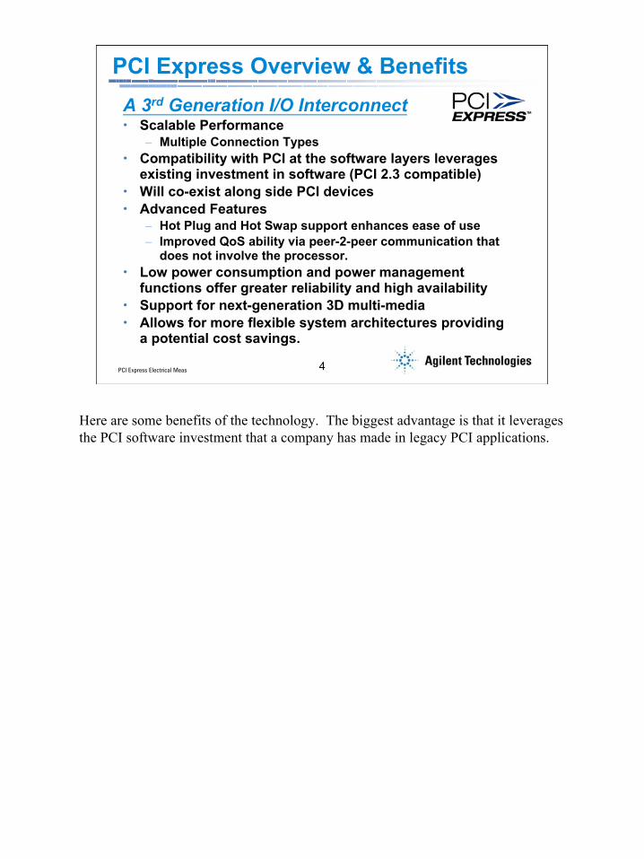
PCI Express Overview & BenefitsA 3rd Generation I/O Interconnect• Scalable Performance
– Multiple Connection Types• Compatibility with PCI at the software layers leverages
existing investment in software (PCI 2.3 compatible)• Will co-exist along side PCI devices• Advanced Features
– Hot Plug and Hot Swap support enhances ease of use– Improved QoS ability via peer-2-peer communication that
does not involve the processor.• Low power consumption and power management
functions offer greater reliability and high availability• Support for next-generation 3D multi-media• Allows for more flexible system architectures providing
a potential cost savings.
Here are some benefits of the technology. The biggest advantage is that it leverages the PCI software investment that a company has made in legacy PCI applications.
PCI Express Electrical Meas 5
5PCI Express Electrical Meas
Agenda
• PCI Express – Next Generation Performance• PCI Express – What you should be testing• PCI Express Compliance – What you will be
judged against• PCI Express Debug – What to do if you
experience a compliance failure• Summary
What is covered in the presentation

PCI Express Electrical Meas 6
6PCI Express Electrical Meas
Electrical Testing Requirements OverviewThis eSeminar covers the ACTIVE electrical testing requirements of the Physical Layer Electrical Sub-block.• PCI Express Base
Specification, Chapter 4 (Transmitters and Receivers)
• PCI Express CEM Specifications, Section 4.7 (Add In Card Connector)
• PCI Express CEM Specification, Section 2.6.3 (Reference Clock)
Here is a high level picture of the PCI Express stack or architecture. We will primarily look at the ACTIVE electrical measurements related tot he Electric Sub-Block.By ACTIVE, I mean measurements with active 2.5 Gb signals. For example, we will not be discussing characterization of backplane impedances.More specifically (click), we will cover the specifications in chapter 4 of the base scec. These specs cover the transmitter and receiver silicon.We will also talk about compliance measurements at the add in card connector, as defined in section 4.7 of the CEM spec.And we will finish up by looking at the reference clock specs, as defined the CEM spec.
PCI Express Electrical Meas 7
7PCI Express Electrical Meas
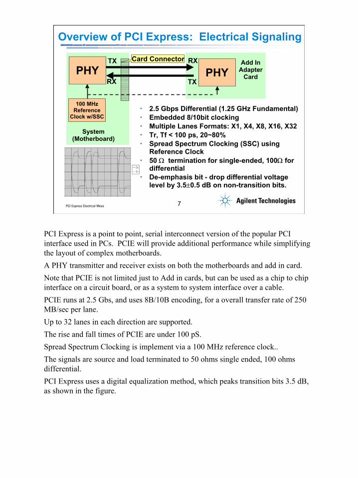
• 2.5 Gbps Differential (1.25 GHz Fundamental)• Embedded 8/10bit clocking • Multiple Lanes Formats: X1, X4, X8, X16, X32• Tr, Tf < 100 ps, 20~80%• Spread Spectrum Clocking (SSC) using
Reference Clock • 50 Ω termination for single-ended, 100Ω for
differential• De-emphasis bit - drop differential voltage
level by 3.5±0.5 dB on non-transition bits.
Overview of PCI Express: Electrical Signaling
PHY PHY
100 MHz Reference
Clock w/SSC
TX
TX
RX
RX
System (Motherboard)
Card Connector Add In Adapter
Card
PCI Express is a point to point, serial interconnect version of the popular PCI interface used in PCs. PCIE will provide additional performance while simplifying the layout of complex motherboards.A PHY transmitter and receiver exists on both the motherboards and add in card. Note that PCIE is not limited just to Add in cards, but can be used as a chip to chip interface on a circuit board, or as a system to system interface over a cable.PCIE runs at 2.5 Gbs, and uses 8B/10B encoding, for a overall transfer rate of 250 MB/sec per lane.Up to 32 lanes in each direction are supported.The rise and fall times of PCIE are under 100 pS.Spread Spectrum Clocking is implement via a 100 MHz reference clock..The signals are source and load terminated to 50 ohms single ended, 100 ohms differential.PCI Express uses a digital equalization method, which peaks transition bits 3.5 dB, as shown in the figure.

PCI Express Electrical Meas 8
8PCI Express Electrical Meas
PCI Express Design & Debug Challenges:Multi-lane Buses
Byte 0
Byte 1
Byte 2
Byte 3
Byte 4
Byte 5
Byte 6
Byte 7
Byte 0
Byte 1
EncoderPar -> Ser
Lane 0
Byte 0
Byte 1
Byte 2
Byte 3
Byte 4
Byte 5
Byte 6
Byte 7
Byte 0
Byte 1
EncoderPar -> Ser
EncoderPar -> Ser
EncoderPar -> Ser
EncoderPar -> Ser
Byte 0 Byte 1 Byte 2 Byte 3
Byte 4 Byte 5 Byte 6 Byte 7
Lane 0 Lane 0 Lane 0 Lane 0
“Byte Striped” Buses
Multi-lane byte striped “busses” require that data on each lane be reconstructed to show true data flow but again make debug much more difficult compared to conventionaly parallel bus structures.

PCI Express Electrical Meas 9
9PCI Express Electrical Meas
PCI Express Design & Debug Challenges:8B/10B Encode/Decode
Framer Determines the sample point for each "Bit Time" on the 10 Bits of data. It locates the proper sample point during a training sequence
D D D D D D D D D D
Framer10B Framed Data
10B to 8B Decode (look up table)
Descrambler
7 6 5 4 3 2 1 0
Serial Data Stream
Originally sent
8 Bits of Data
Optional
Conceptual 8B/10B Decode
8B/10B and optional bit scrambling can help reduce EMI problems but can also make the interconnect harder to debug logically.

PCI Express Electrical Meas 10
10PCI Express Electrical Meas
PCI Express Design & Debug Challenges:
Chip-to-Chip and Microwave bus speeds
Device BDevice A
1 Lane = 2 Differential Pairs (1 send, 1 receive)
• Dual Simplex Point-to-PointTopology
• LVDS (Low Voltage Differential Signaling) Technology
• ≥ 2.5 Gb/s per Lane/direction• Selectable Lane Width
– x1, x4, x8, x16, x32
Problem Areas:• Crosstalk• Impedance
Discontinuities• Reflections• InterSymbol Interference• Mode Conversion
PCI Express using high speed, 2.5Gbit/s serial links can suffer from a large array of physical phenomena including crosstalk, impedance discontinuities resulting in reflections (causing jitter), intersymbol interference, and mode conversion due to unbalanced transmission lines can lead to excessive EMI emissions in a large system.
PCI Express Electrical Meas 11
11PCI Express Electrical Meas
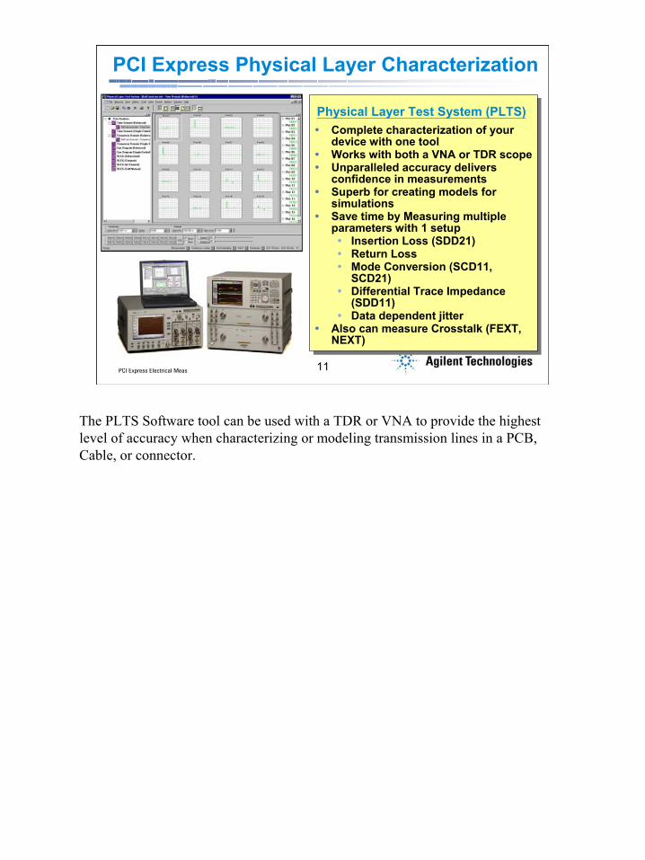
PCI Express Physical Layer Characterization
Complete characterization of your device with one toolWorks with both a VNA or TDR scope Unparalleled accuracy delivers confidence in measurementsSuperb for creating models for simulationsSave time by Measuring multiple parameters with 1 setup
Insertion Loss (SDD21)Return LossMode Conversion (SCD11, SCD21)Differential Trace Impedance (SDD11)Data dependent jitter
Also can measure Crosstalk (FEXT, NEXT)
Physical Layer Test System (PLTS)
The PLTS Software tool can be used with a TDR or VNA to provide the highest level of accuracy when characterizing or modeling transmission lines in a PCB, Cable, or connector.

PCI Express Electrical Meas 12
12PCI Express Electrical Meas
Device Characterization: Transmitters
Measurements performed with an Equivalent Time Oscilloscope
• Can also use a VNA for Return Loss Measurements.
• Could measure UI time, Voltages, Eye Mask, Idle timing, Land Skew w/clock recovery
Rise time, Fall time, Impedance, Return Loss *
86100C DCA-J Sampling Oscilloscope w/TDR & PLTS
Measurements
To fully characterize a PCI Express Transmitter, both an real time and sampling scope in needed.The table lists all the measurements needed, based upon the PCI Express specification. Most specification are required to be measured over 250 consecutive UI (unit intervals), and therefore require a real time scope with serial data analysis capability. A sampling scope does not measure consecutive UIs. However, the risetime specification is too fast for real time scopes available today, so a sampling scope must be used. Also, the sampling scope provides TDR capability which is used tom measure the impedance.The return loss can be measured with a TDR and PLTS software, or alternatively, a VNA can be used.For the most accurate measurements, a direct connection from the transmitter’s TX output to the scope inputs should be used. This offer the lowest noise measurement. If a direct connection is not possible, then a differential prove proves good performance also, but adds a small amount of noise and jitter to the measurement.In the case of the risetime, impedance, and return loss measurements, a direction connection is required.

PCI Express Electrical Meas 13
13PCI Express Electrical Meas
Device Characterization: TransmittersMeasurements performed with a Real Time Oscilloscope
PHY Transmitter
TX+TX-
A direct connection provides best performance; and is required for measurement of rise time, impedance, and return loss. A probe connection is good when a direct connection is not possible.
UI time, Voltages, Eye Mask, Jitter, Idle Timing, Lane Skew
54855A 6 GHz Real Time Oscilloscope w/E2688A SDA
Measurements
To fully characterize a PCI Express Transmitter, both an real time and sampling scope in needed.The table lists all the measurements needed, based upon the PCI Express specification. Most specification are required to be measured over 250 consecutive UI (unit intervals), and therefore require a real time scope with serial data analysis capability. A sampling scope does not measure consecutive UIs. However, the risetime specification is too fast for real time scopes available today, so a sampling scope must be used. Also, the sampling scope provides TDR capability which is used tom measure the impedance.The return loss can be measured with a TDR and PLTS software, or alternatively, a VNA can be used.For the most accurate measurements, a direct connection from the transmitter’s TX output to the scope inputs should be used. This offer the lowest noise measurement. If a direct connection is not possible, then a differential prove proves good performance also, but adds a small amount of noise and jitter to the measurement.In the case of the risetime, impedance, and return loss measurements, a direction connection is required.
PCI Express Electrical Meas 14
14PCI Express Electrical Meas
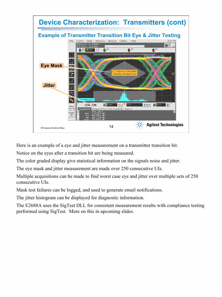
Device Characterization: Transmitters (cont)
Example of Transmitter Transition Bit Eye & Jitter Testing
Jitter
Eye Mask
Here is an example of a eye and jitter measurement on a transmitter transition bit.Notice on the eyes after a transition bit are being measured.The color graded display give statistical information on the signals noise and jitter.The eye mask and jitter measurement are made over 250 consecutive UIs.Multiple acquisitions can be made to find worst case eye and jitter over multiple sets of 250 consecutive UIs.Mask test failures can be logged, and used to generate email notifications.The jitter histogram can be displayed for diagnostic information.The E2688A uses the SigTest DLL for consistent measurement results with compliance testing performed using SigTest. More on this in upcoming slides.

PCI Express Electrical Meas 15
15PCI Express Electrical Meas
Device Characterization: Receivers
• Most testing can be performed with an 81134A Pulse Pattern Generator and a function generator as the stimulus source.
• An oscilloscope & probe is used to monitor the signal into the receiver.
• An oscilloscope or logic analyzer is used to monitor the response from the device.
• Receiver input impedance and return loss is measured with a TDR or VNA.
* More Info: Agilent Product Note 5988-7432EN
A signal generator is used to stimulate the receiver, and the response of device is monitored*
Receivers must be tested for the sensitivity, and tolerance to jitter. The testing methodology is to provide a stimulus to the RX input of a device, and monitor the response from the device via the TX pins. Note that this testing methodology assumes that the device’s is functional enough to response correctly to Training Set inputs on it’s RX inputs.An signal generator such as the Agilent 81134A is ideally suited for most tests, the exception being lane to lane skew tests.A function generator is used to add jitter to the stimulus signal.The signal should be monitored at the device’s input pins with an oscilloscope and probe, to know what the actual signal amplitude and jitter is AT the device’s input.The response from the device can be monitored with an oscilloscope or logic analyzer.In additional to sensitivity and jitter tolerance, the receiver's input impedance and return loss must be measured with a TDR or VNA.For more receiver testing, Agilent has a detailed product note, part number 5988-7432EN. This product note can be found by typing the part number in the search window at www.agilent.com.
PCI Express Electrical Meas 16
16PCI Express Electrical Meas
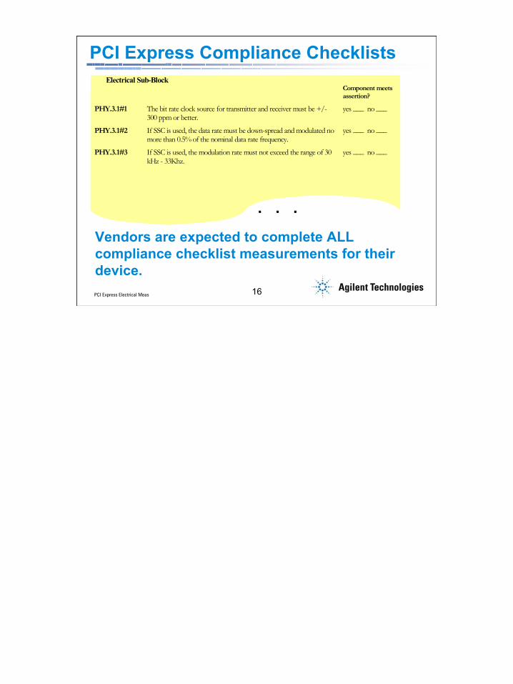
PCI Express Compliance ChecklistsElectrical Sub-Block
Component meets assertion?
PHY.3.1#1 The bit rate clock source for transmitter and receiver must be +/- 300 ppm or better.
yes ___ no ___
PHY.3.1#2 If SSC is used, the data rate must be down-spread and modulated no more than 0.5% of the nominal data rate frequency.
yes ___ no ___
PHY.3.1#3 If SSC is used, the modulation rate must not exceed the range of 30 kHz - 33Khz.
yes ___ no ___
Vendors are expected to complete ALL compliance checklist measurements for their device.
. . .

PCI Express Electrical Meas 17
17PCI Express Electrical Meas
Agenda
• PCI Express – Next Generation Performance• PCI Express – What you should be testing• PCI Express Compliance – What you will be
judged against• PCI Express Debug – What to do if you
experience a compliance failure• Summary
What is covered in the presentation

PCI Express Electrical Meas 18
18PCI Express Electrical Meas
Compliance = Interoperability = Market Adoption
• PCI-SIG & Intel collaborate for compliance testingIntel developed compliance utility: SigTestIntel developed compliance fixtures:
Compliance Load Board (CLB), Compliance Base Board (CBB)Testing is not comprehensive (audit only)
Compliance is necessary to ensure products are interoperable. Nobody wants to buy a hot new graphics card from ATI only to find out that it doesn’t work in their Intel motherboard.

PCI Express Electrical Meas 19
19PCI Express Electrical Meas
What’s a Plugfest?• PCI Express Logo Program
– Vendors must validate system platforms and add-in cards to make “Integrator’s List”
• PCI-SIG (Special Interest Group) Governing Body– Drive Specification Development– Authorization/Enforcement of Logo Usage– Organize and Conduct Plugfests
• Interoperability is the Main Goal• Plugfest Events Occur quarterly in Milpitas, CA and
sometimes elsewhere (Taiwan, …)• Testing requires a 6 GHz, 20 GSa/s real time scope
(Agilent 54855A), fixture boards, and SigTest measurement application.
Plugfests are crucial to ensuring interoperability. Here vendors qualify their products for consistency with the PCI Express standard.
PCI Express Electrical Meas 20
20PCI Express Electrical Meas
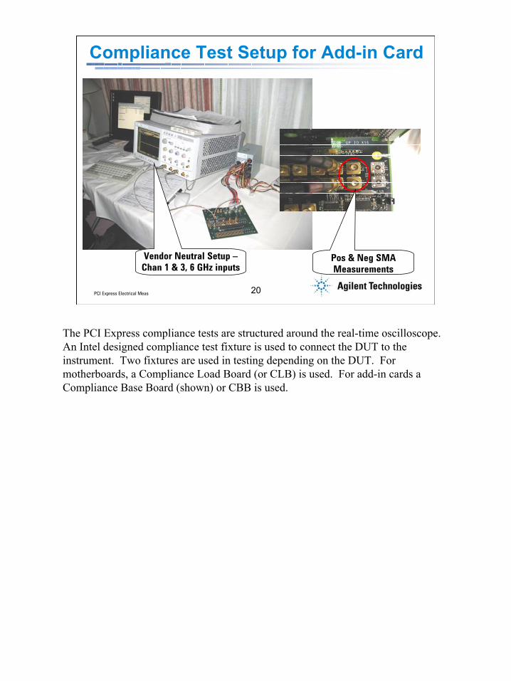
Compliance Test Setup for Add-in Card
Pos & Neg SMA Measurements
Vendor Neutral Setup –Chan 1 & 3, 6 GHz inputs
The PCI Express compliance tests are structured around the real-time oscilloscope. An Intel designed compliance test fixture is used to connect the DUT to the instrument. Two fixtures are used in testing depending on the DUT. For motherboards, a Compliance Load Board (or CLB) is used. For add-in cards a Compliance Base Board (shown) or CBB is used.
PCI Express Electrical Meas 21
21PCI Express Electrical Meas
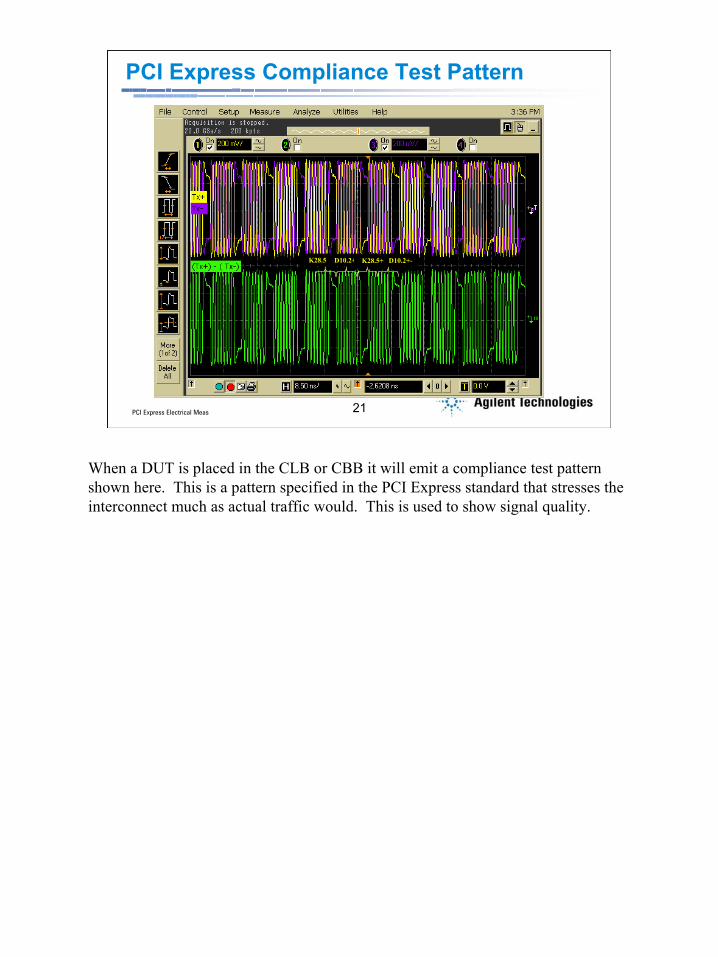
PCI Express Compliance Test Pattern
K28.5- D10.2+ D10.2+-K28.5+
When a DUT is placed in the CLB or CBB it will emit a compliance test pattern shown here. This is a pattern specified in the PCI Express standard that stresses the interconnect much as actual traffic would. This is used to show signal quality.
PCI Express Electrical Meas 22
22PCI Express Electrical Meas
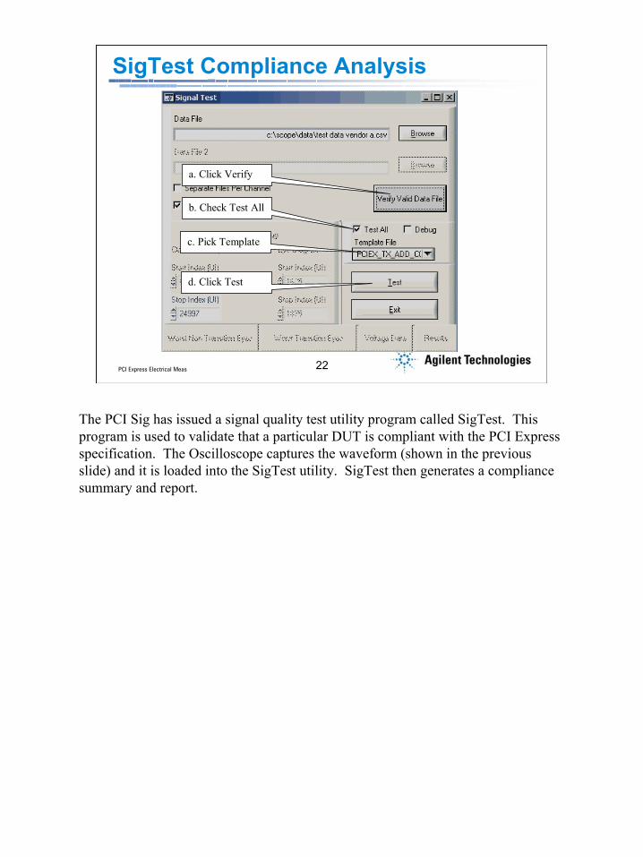
SigTest Compliance Analysis
a. Click Verify
b. Check Test All
c. Pick Template
d. Click Test
The PCI Sig has issued a signal quality test utility program called SigTest. This program is used to validate that a particular DUT is compliant with the PCI Express specification. The Oscilloscope captures the waveform (shown in the previous slide) and it is loaded into the SigTest utility. SigTest then generates a compliance summary and report.

PCI Express Electrical Meas 23
23PCI Express Electrical Meas
SigTest Compliance Analysis
The PCI Sig has issued a signal quality test utility program called SigTest. This program is used to validate that a particular DUT is compliant with the PCI Express specification. The Oscilloscope captures the waveform (shown in the previous slide) and it is loaded into the SigTest utility. SigTest then generates a compliance summary and report.
PCI Express Electrical Meas 24
24PCI Express Electrical Meas
SigTest Report of Results
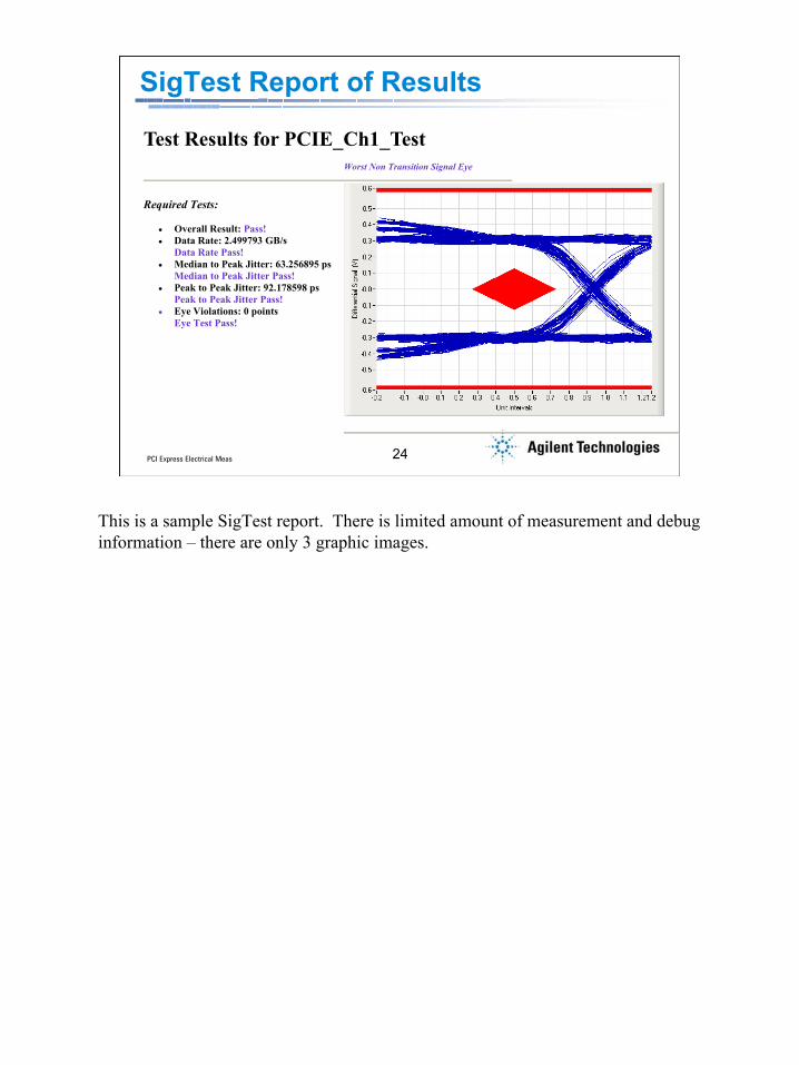
Test Results for PCIE_Ch1_Test
Required Tests:
• Overall Result: Pass! • Data Rate: 2.499793 GB/s
Data Rate Pass! • Median to Peak Jitter: 63.256895 ps
Median to Peak Jitter Pass! • Peak to Peak Jitter: 92.178598 ps
Peak to Peak Jitter Pass! • Eye Violations: 0 points
Eye Test Pass!
Worst Non Transition Signal Eye
This is a sample SigTest report. There is limited amount of measurement and debug information – there are only 3 graphic images.

PCI Express Electrical Meas 25
25PCI Express Electrical Meas
Agilent N5393A PCI Express Compliance &
Validation Tool SuiteGuided
operation
Select tests to make
• Key Features:– Test setup wizard for ease-
of-use– Wide range of electrical tests– Automated scope
measurement setup– Test results report generation– Pass/fail margin analysis
• Key Benefits:– Saves time on complex tests– Easy UI– Good debug and analysis
tool
Keep in mind that SigTest covers only a subset of the physical layer tests required by the spec. It should be considered an audit verification. Vendors are still required to do all of the tests called for in the PCI Express specification. The Agilent N5393A Compliance and validation test suite is a structured, automated measurement application that performs many more tests than SigTest. Used in conjunction with the E2688A Serial Data Analysis application, the N5393A forms a powerful debug tool for identifying and fixing compliance failures.
The software is very easy to use. You start by defining which tests you want to make. When you click on a measurement, a short description appears in the bottom window.

PCI Express Electrical Meas 26
26PCI Express Electrical Meas
Test Setup Configuration
Define the configuration value or state
Present selection is displayed
The next step is to configure the test setup. Here you can add information about the test device, define how it is connected to the scope, etc. to guide the software.
PCI Express Electrical Meas 27
27PCI Express Electrical Meas
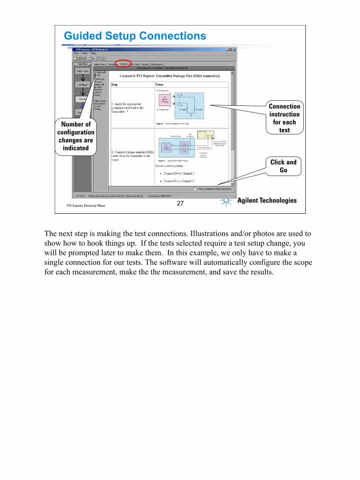
Guided Setup Connections
Connection instruction
for each test
Number of configuration changes are
indicated
Click and Go
The next step is making the test connections. Illustrations and/or photos are used to show how to hook things up. If the tests selected require a test setup change, you will be prompted later to make them. In this example, we only have to make a single connection for our tests. The software will automatically configure the scope for each measurement, make the the measurement, and save the results.
PCI Express Electrical Meas 28
28PCI Express Electrical Meas
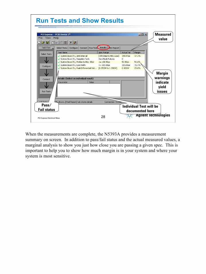
Run Tests and Show Results
Pass/Fail status
Measured value
Margin warnings indicate
yield issues
Individual Test will be documented here
When the measurements are complete, the N5393A provides a measurement summary on screen. In addition to pass/fail status and the actual measured values, a marginal analysis to show you just how close you are passing a given spec. This is important to help you to show how much margin is in your system and where your system is most sensitive.

PCI Express Electrical Meas 29
29PCI Express Electrical Meas
HTML Report Test Summary
Pass/Fail status
Margin warning
thresholds
DUT documentation
Measured value
Margin warnings
For more extensive measurement results, an HTML report format is available. Here you get documentation on the DUT and test setup, your margin thresholds, and the results. Like the on screen display, pass/fail status, actual measure values, and margin are displayed.
PCI Express Electrical Meas 30
30PCI Express Electrical Meas
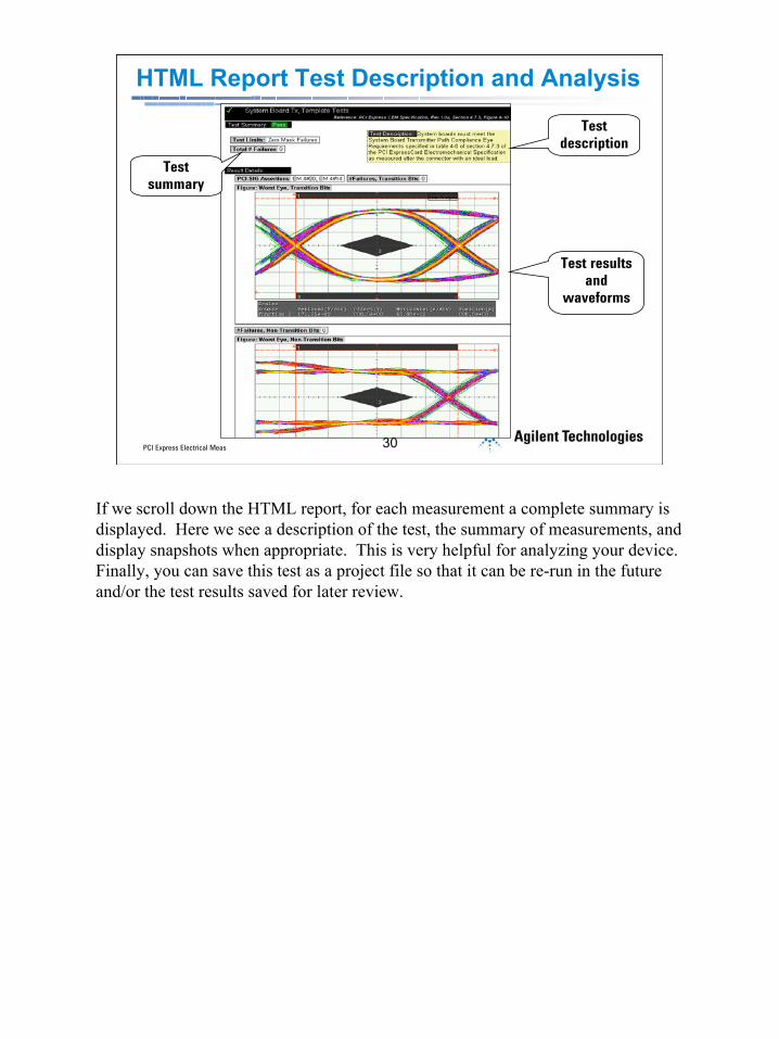
HTML Report Test Description and Analysis
Test description
Test summary
Test results and
waveforms
If we scroll down the HTML report, for each measurement a complete summary is displayed. Here we see a description of the test, the summary of measurements, and display snapshots when appropriate. This is very helpful for analyzing your device. Finally, you can save this test as a project file so that it can be re-run in the future and/or the test results saved for later review.

PCI Express Electrical Meas 31
31PCI Express Electrical Meas
Reference Clock
• The system board provides a 100 MHz reference for transmitter and receiver synchronization and SSC tracking– The reference clock specifications can be measured
with an Agilent 54855A scope and two 1134A InfiniiMaxprobes.
– Jitter analysis software is required to measure the clock jitter and SSC profile.
– The 1 Meg memory option is also required to measure the SSC profile.
System boards provide a 100 MHz reference clock to all transmitters and receivers.The transmitters generate their TX clock from this reference.The receivers may use the ref clock, depending on the receiver architecture used.Spread Spectrum may be applied to the reference clock, at a rate of 0.5% at 33 kHz. This will propagate to the TX clocks in the transmitters. Some reciever architectures will need to use the refclock to adequately track the SSC.The reference clock can be measured with an Agilent 6 GHz real time scope and two probe. Two probes are required because the specifications call out some single ended specs.A jitter analysis option is needed to make the jitter measurement, and to perform an measurements of the SSC profile. Either the E2681 or E2690 will suffice for this.For SSC measurements, the 1 Meg memory options is needed to capture at least one cycle of the SSC.
PCI Express Electrical Meas 32
32PCI Express Electrical Meas
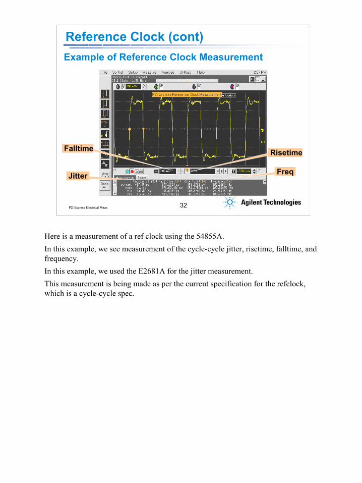
Example of Reference Clock Measurement
Jitter Freq
RisetimeFalltime
Reference Clock (cont)
Here is a measurement of a ref clock using the 54855A. In this example, we see measurement of the cycle-cycle jitter, risetime, falltime, and frequency.In this example, we used the E2681A for the jitter measurement.This measurement is being made as per the current specification for the refclock, which is a cycle-cycle spec.

PCI Express Electrical Meas 33
33PCI Express Electrical Meas
Agenda
• PCI Express – Next Generation Performance• PCI Express – What you should be testing• PCI Express Compliance – What you will be
judged against• PCI Express Debug – What to do if you
experience a compliance failure• Summary
What is covered in the presentation
PCI Express Electrical Meas 34
34PCI Express Electrical Meas
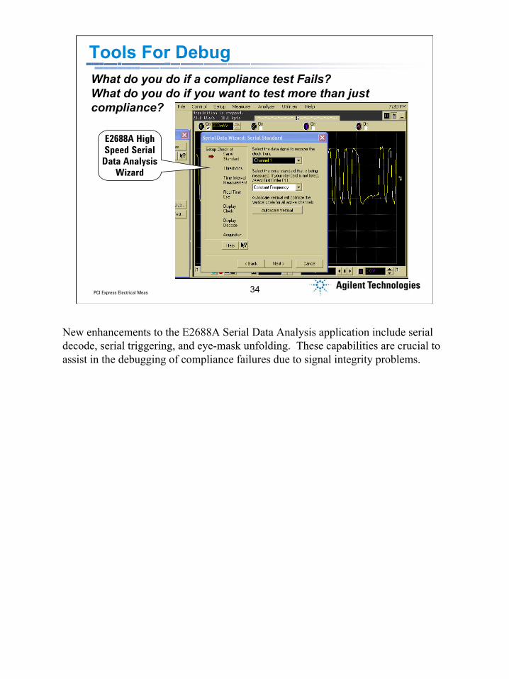
Tools For DebugWhat do you do if a compliance test Fails?What do you do if you want to test more than just compliance?
E2688A High Speed Serial Data Analysis
Wizard
New enhancements to the E2688A Serial Data Analysis application include serial decode, serial triggering, and eye-mask unfolding. These capabilities are crucial to assist in the debugging of compliance failures due to signal integrity problems.

PCI Express Electrical Meas 35
35PCI Express Electrical Meas
Serial Decode of a PCI Express Signal (setup)
Here you can see the setup for serial decode of the PCI Express signal. The breakthrough discovered here is that each standard has a specific sequence of 0’s and 1’s that are unique. Once we locate this alignment character we are able to decode the entire trace into multiple formats. Supported standards for decode include PCI Express, Fibre-Channel, SATA, and InfiniBand. A custom decode option for proprietary standards is also provided.
PCI Express Electrical Meas 36
36PCI Express Electrical Meas
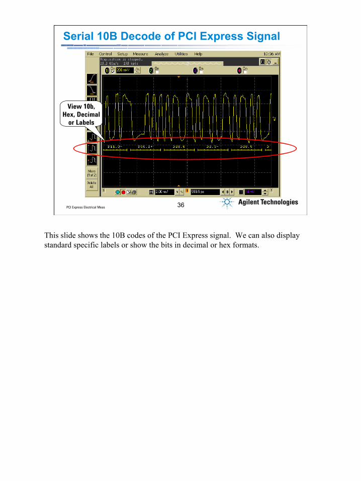
Serial 10B Decode of PCI Express Signal
View 10b, Hex, Decimal
or Labels
This slide shows the 10B codes of the PCI Express signal. We can also display standard specific labels or show the bits in decimal or hex formats.
PCI Express Electrical Meas 37
37PCI Express Electrical Meas
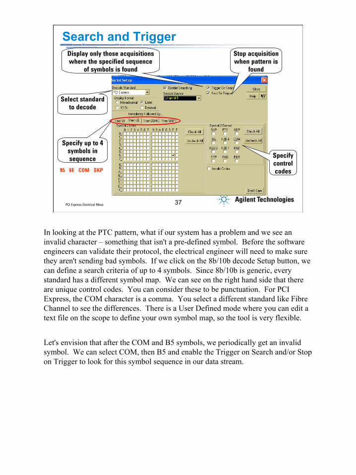
Search and Trigger
Specify up to 4 symbols in sequence
Stop acquisition when pattern is
found
Display only those acquisitions where the specified sequence
of symbols is found
Select standard to decode
Specify control codes95 6E COM SKP
In looking at the PTC pattern, what if our system has a problem and we see an invalid character – something that isn't a pre-defined symbol. Before the software engineers can validate their protocol, the electrical engineer will need to make sure they aren't sending bad symbols. If we click on the 8b/10b decode Setup button, we can define a search criteria of up to 4 symbols. Since 8b/10b is generic, every standard has a different symbol map. We can see on the right hand side that there are unique control codes. You can consider these to be punctuation. For PCI Express, the COM character is a comma. You select a different standard like Fibre Channel to see the differences. There is a User Defined mode where you can edit a text file on the scope to define your own symbol map, so the tool is very flexible.
Let's envision that after the COM and B5 symbols, we periodically get an invalid symbol. We can select COM, then B5 and enable the Trigger on Search and/or Stop on Trigger to look for this symbol sequence in our data stream.
PCI Express Electrical Meas 38
38PCI Express Electrical Meas
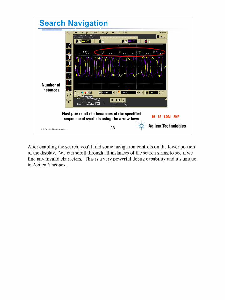
Search Navigation
Navigate to all the instances of the specified sequence of symbols using the arrow keys 95 6E COM SKP
Number of instances
After enabling the search, you'll find some navigation controls on the lower portion of the display. We can scroll through all instances of the search string to see if we find any invalid characters. This is a very powerful debug capability and it's unique to Agilent's scopes.
PCI Express Electrical Meas 39
39PCI Express Electrical Meas
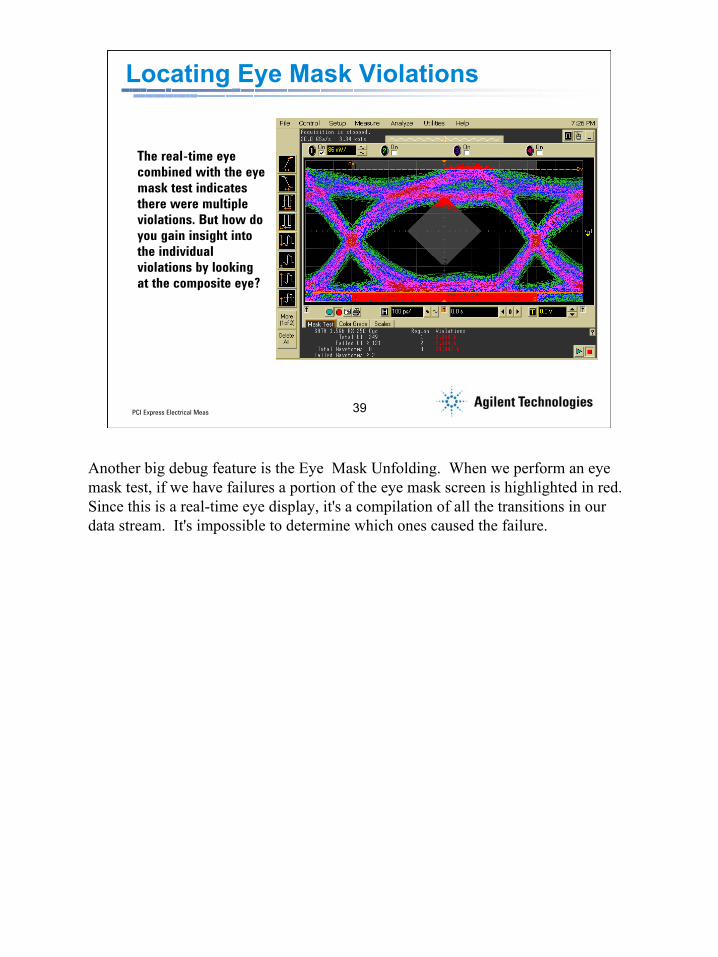
Locating Eye Mask Violations
The real-time eye combined with the eye mask test indicates there were multiple violations. But how do you gain insight into the individual violations by looking at the composite eye?
Another big debug feature is the Eye Mask Unfolding. When we perform an eye mask test, if we have failures a portion of the eye mask screen is highlighted in red. Since this is a real-time eye display, it's a compilation of all the transitions in our data stream. It's impossible to determine which ones caused the failure.
PCI Express Electrical Meas 40
40PCI Express Electrical Meas
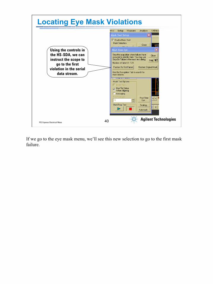
Locating Eye Mask Violations
Using the controls in the HS-SDA, we can instruct the scope to
go to the first violation in the serial
data stream.
If we go to the eye mask menu, we’ll see this new selection to go to the first mask failure.

PCI Express Electrical Meas 41
41PCI Express Electrical Meas
Locating Eye Mask Violations
Navigate to all the instances of the eye mask violation using the arrow keys
Number of instances
Mask Failure
Like the symbol search, the eye mask unfold will let us scroll through all the sequences in our data stream that failed the eye mask test. Now we can see that the failed waveform, in this case the signal failed the maximum voltage test and we have a better understanding of what we will need to fix.

PCI Express Electrical Meas 42
42PCI Express Electrical Meas
Agenda
• PCI Express – Next Generation Performance• PCI Express – What you should be testing• PCI Express Compliance – What you will be
judged against• PCI Express Debug – What to do if you
experience a compliance failure• Summary
What is covered in the presentation
PCI Express Electrical Meas 43
43PCI Express Electrical Meas
PCI Express Electrical Layer Validation
• Transmission Line Characterization• Device Transmitter/Receiver
Characterization• Compliance Testing• Debug
PCI Express Electrical Meas 44
44PCI Express Electrical Meas
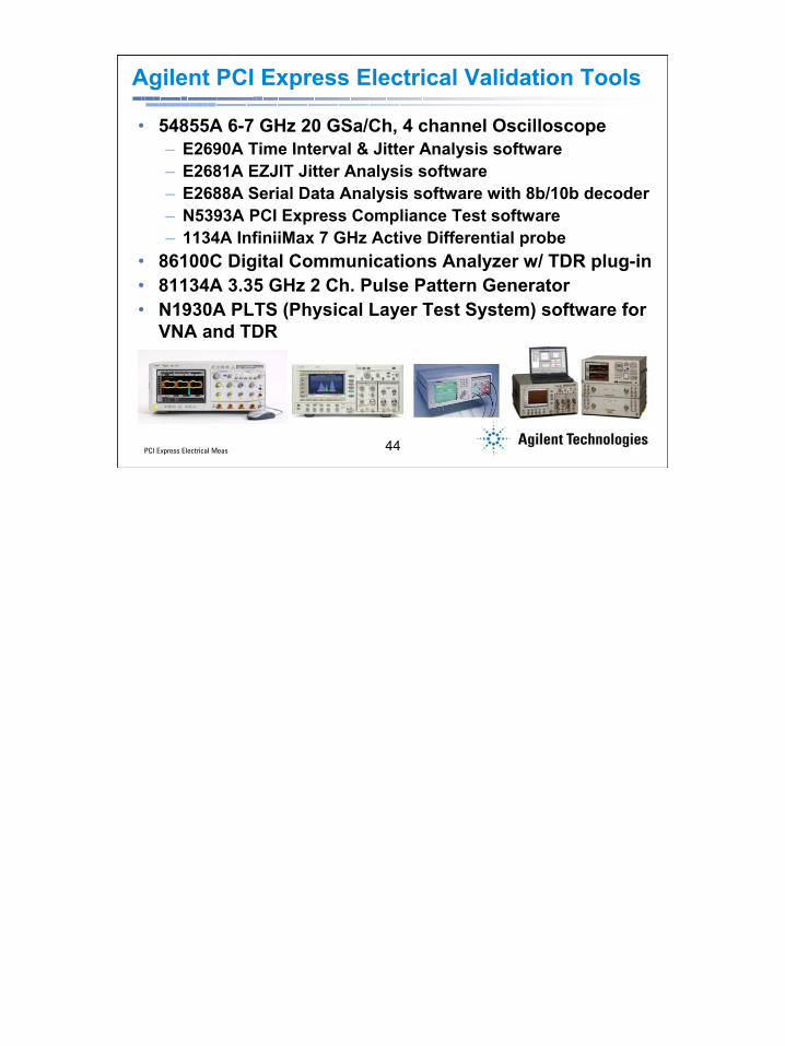
Agilent PCI Express Electrical Validation Tools
• 54855A 6-7 GHz 20 GSa/Ch, 4 channel Oscilloscope– E2690A Time Interval & Jitter Analysis software– E2681A EZJIT Jitter Analysis software– E2688A Serial Data Analysis software with 8b/10b decoder– N5393A PCI Express Compliance Test software– 1134A InfiniiMax 7 GHz Active Differential probe
• 86100C Digital Communications Analyzer w/ TDR plug-in• 81134A 3.35 GHz 2 Ch. Pulse Pattern Generator• N1930A PLTS (Physical Layer Test System) software for
VNA and TDR

PCI Express Electrical Meas 45
45PCI Express Electrical Meas
N4901 Serial BERT81250 ParBERT
86100C DCA-J with TDR
81134APulse Generator
N1930A PhysicalLayer Test System
(VNA or TDR)
16900 Logic Analyzer
54855A InfiniiumOscilloscope
E2969A PCI Express Protocol
Test Card
E2960 Exerciser/Analyzer
N4220B PacketAnalysis Probe
Agilent PCI Express Tools
Agilent is ready now with solutions to address problems across the entire spectrum of the PCI express application space. From physical layer testing to application testing.
PCI Express Electrical Meas 46
46PCI Express Electrical Meas
Agilent Technologies:A Core Player in the PCI Express World• Key contributor in the PCI-SIG• Heavily involved in compliance and interoperability tests
(since PCI intro)• Agilent, Intel and Xilinx demo the world’s first PCI Express
system in IDF-Spring, Feb. 2004 • Agilent 54855A Infiniium Oscilloscope adopted at IDF 2003
San Jose due to it’s superior accuracy and probing system• Jointly developed and announced with Intel Corp the
E2969A PCI Express Protocol Test Card at the PCI SIG Developers Conference in June 2003
• Introduced the world’s first PCI Express Exerciser/Analyzer (E2960) at the PCI SIG Developers Conference in June 2003
Agilent has been and continues to be a strong force in support of PCI and PCI Express. Agilent has forged a very close relationship with the PCI-Sig and Intel to offer leading solutions for PCI Express developers.

PCI Express Electrical Meas 47
47PCI Express Electrical Meas
Resources
• PCI Express Products & Application Info www.agilent.com/find/pci_express
• Signal Integrity Application Infowww.agilent.com/find/si
• Jitter Application Infowww.agilent.com/find/jitter_info
• PCI SIGwww.pcisig.com
Agilent’s list of application information is continually growing. See the web site on this slide for the lastest information on application notes, design guides, and solution information for PCI Express deployment.