PATENTE Minty Boost
99
Minty Boost Created by Ladyada Last updated on 2013-12-09 01:30:46 PM EST
-
Upload
brian162006 -
Category
Documents
-
view
243 -
download
0
Transcript of PATENTE Minty Boost

Minty BoostCreated by Ladyada
Last updated on 2013-12-09 01:30:46 PM EST
2666688999999
910101010101010
11
1111
1111
Guide Contents
Guide ContentsOverviewMinty Boost: Portable USB power
A small battery-powered USB chargerOverviewReviews & GalleryDevice Compatibility
F.A.Q.Frequently Asked Questions
It works! But then the iPod/iPhone/device gets drained...what's up?How come my iPhone/iTouch doesn't completely charge?Will the MintyBoost charge my device?ARRGH! It doesn't work!I get the right voltages but it doesn't charge my favorite gadget! Is the kit a "USBSpecification" Charger? If not, how can I make it into one?Can I buy a pre-made/pre-built MintyBoost?What does the MintyBoost kit come with?How many charges/hours of use can I get out of a MintyBoost?I want better performance, should I attach 3 or 4 AA batteries? How about a 9V?OK but what if I want 4 AA's, 2 sets of 2 in parallel?When I use the kit, the chip/batteries seems warm or hot...Is this OK?But it's really hot and I'm worried!When I plug in a device, sometimes theres a 'hum', 'hiss', 'squeak', 'whine', etc noise...isthis normal?If this is a charger, why are the data (D+ and D-) lines used? Why doesn't the 3Gs workwith the Mintyboost v2, but the older iPhone does? What are the pullup/down resistorsused for, and which should I use?Does the v1.x work with iPhone/iTouch? Does the v2.0?Can I convert a v1.x kit to a v2.x? Can I use a MAX756 in a v2.x or a LT1302-5 in av1.x?Why doesn't the v1.2 kit come with R1-R3 and LED1
© Adafruit Industries http://learn.adafruit.com/minty-boost Page 2 of 99
1112131313131414171717192022222426262641454545464646464646464748
I'm trying to make/breadboard this kit on my own and it's not working! HELP ME!Do you have any high rez photos?
Make it!Make your own
Make it!Older soldering instructions!
PreparationTools
Parts listCheck your kit!Parts list for v3.0Schematic for v3.0Parts list for v2.0Schematic for v2.0Parts list for v1.2Schematic for v1.2
Solder itInstructions for Version 3.0Solder It!
Case itUse it!Tips and tricks, how to use your MintyBoost
The MintyBoost User manual!How to useBasic User Manual
Go MintyBoost!CompatibilityWhich batteries to use?How to chargeWhile charging...When to stop charging
Batteries
© Adafruit Industries http://learn.adafruit.com/minty-boost Page 3 of 99
484848484949505051525252545454545555565657575758585859606060606363
User manual - Choosing batteriesBatteries?How the mintyboost worksStandard AA'sRechargable AA'sAlkaline or rechargable?Bigger batteries? More batteries?Lithium Ion PolymerHow many recharges will I get?Detailed guidelines - Voltage RequirementsDetailed guidlines - Current RequirementsTons of info!
Compat v3Device Compatibility list for v3
Verison 3 mintyboosts!Apple ProductsHTCLGMotorolaSamsungSony EricssonNokiaRIMMore Phones!eBook ReadersHandheld GamesMP3 Player
Compat v2Device Compatibility for v2.x Mintyboosts
For version 2.x only!Mintyboost Compatibility chart!
ProcessHow to: How to
© Adafruit Industries http://learn.adafruit.com/minty-boost Page 4 of 99
636364647071727879828488888888898990919296969696969697979999999999
Meta DocumentationOriginal IdeaEngineering better!Case in pointBasic BoostInductive reasoningRapid prototyping #1Testing the prototypeVerifying the mathKit budgetingFinishing up
iChargingThe mysteries of Apple device charging
The VideoQuick introduction to USBUsing USB as a power supplyiCharge!First attemptThe iPhone and larger iPodsiPhones
Change LogWhat's changed?
A long history of boostingV1.0 - June 2006 (first release)v1.1 - July 2006v1.2 - April 2007v2.0 - August 2008v3.0 - August 2010
DownloadDownloads
v2.0 filesv1.0, v1.1 and v1.2 filesDatasheets
© Adafruit Industries http://learn.adafruit.com/minty-boost Page 5 of 99
Overview
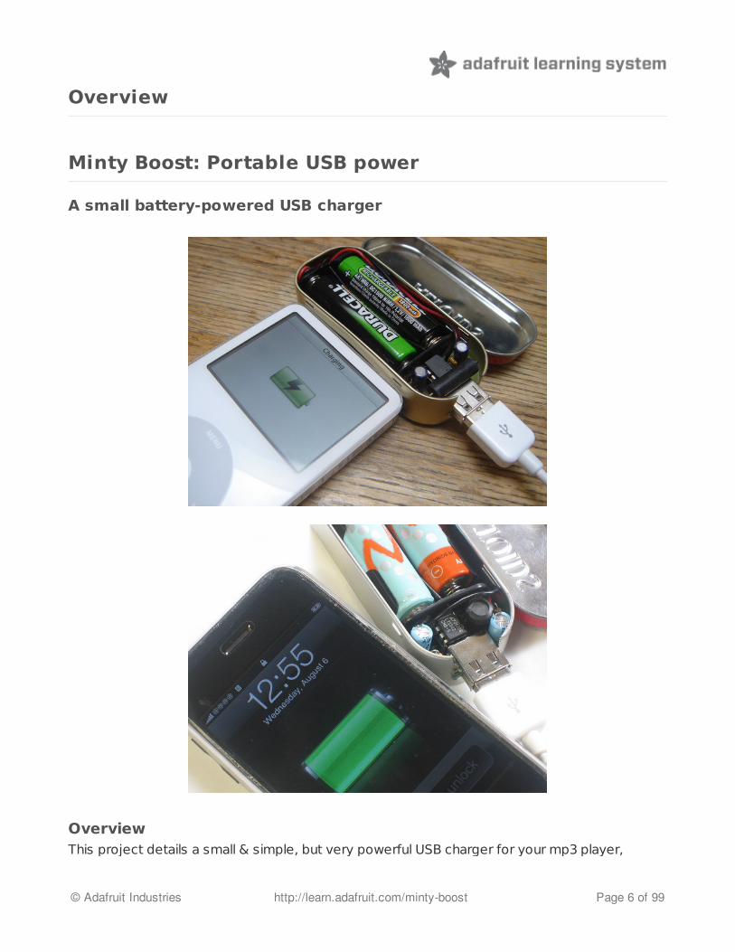
Minty Boost: Portable USB power
A small battery-powered USB charger
OverviewThis project details a small & simple, but very powerful USB charger for your mp3 player,
© Adafruit Industries http://learn.adafruit.com/minty-boost Page 6 of 99
camera, cell phone, and just about any other gadget you can plug into a USB port to charge!(See below for compatibility tests.)
The charger circuitry and 2 AA batteries fit into an Altoids gum tin, and will run your iPod forhours! 2.5x more than you'd get from a 9V USB charger! (See Process (http://adafru.it/c34) formath/calculations) You can use rechargable batteries too (http://adafru.it/c35).
Specifications:
Version 3 now works with iPhones and newer iGadgets!5V output @ 500mA outputFits in your pocketRecharges just about any gadget with a USB cableUses any AA batteries! (http://adafru.it/c35)Upgrade to C or D cells for a mega battery pack (http://adafru.it/c35)
Some numbers...
iPhone (all types): 3/4 full rechargeiPod video (tested, using alkaline batteries): 3hrs more video (1 full recharge)iPod mini (tested w/rechargables): 26 hours more (1.5 full recharges)iPod nano: 4 full recharges!iPod shuffle : 60 hours more , 5 full recharges!
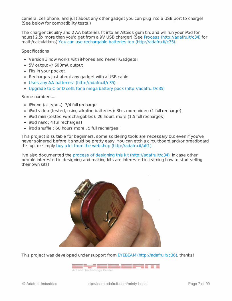
This project is suitable for beginners, some soldering tools are necessary but even if you'venever soldered before it should be pretty easy. You can etch a circuitboard and/or breadboardthis up, or simply buy a kit from the webshop (http://adafru.it/aK1).
I've also documented the process of designing this kit (http://adafru.it/c34), in case otherpeople interested in designing and making kits are interested in learning how to start sellingtheir own kits!
This project was developed under support from EYEBEAM (http://adafru.it/c36), thanks!
© Adafruit Industries http://learn.adafruit.com/minty-boost Page 7 of 99

This website and all original content therein is published under the CreativeCommons (http://adafru.it/c37) 2.5 attribution license.
Reviews & GalleryRead what some people have to say! (And let me know if you have a review you'd like linked tofrom here)
Paul Stamatiou's review (http://adafru.it/c38)Jim Wandering's review (http://adafru.it/c39)Daniel Beck's review (http://adafru.it/c3a)Ryan Pauley's philosophical review (http://adafru.it/c3b)The Samurai's gallery (http://adafru.it/c3c)Erike built one for his sweetheart (http://adafru.it/c3d)Bean tooth made a cherry flavored one (http://adafru.it/c3e)Piet in Finland uses his for watching long videos (http://adafru.it/c3f)Lexiredlion built 5! (http://adafru.it/c3g)
Device CompatibilityHey we moved this really long list to the user manual, please go there to see compatibilitycharts for versions 2 and 3 of the mintyboost! (http://adafru.it/c3h)
Mintyboost® is a registered trademark of Adafruit Industries
© Adafruit Industries http://learn.adafruit.com/minty-boost Page 8 of 99

F.A.Q.
Frequently Asked Questions
It works! But then the iPod/iPhone/device gets drained...what's up?This is a common problem with iPods/iPhone/iTouch. These devices have very large batteriesand they have an annoying bug that if they -think- they're being charged they'll stay on and not'go to sleep' conserving power. That means that if the AA batteries die before the device isdone charging, the device will stay on at full power because it thinks it is plugged into the wall.This can cause it to drain the battery. The best suggestion is to use fresh/chargedbatteries and don't leave it plugged in overnight.
This is especially true of iPhones, as they suck out all the battery power in a little less than anhour in order to 'quick charge'. This reduces the capacity of the batteries, but means that yourphone will be up and running faster.
Once you see the charging icon change from a plug, the mintyboost is 'dead' and you mustunplug it. For more information, see the user manual. (http://adafru.it/c3i)
How come my iPhone/iTouch doesn't completely charge?iPhone/iTouch's have batteries that are so large there is no way to fully chargethem on 2 AA's. You can only charge 1/2 of a battery because the AA's will diebefore finishing. You should use the Mintyboost to 'boost' it, but not as a way to fill thewhole battery to full.
Will the MintyBoost charge my device?Very likely! Check out our compatibility lists for more information about your favvygadget (http://adafru.it/c3h). If you find a new device that it does/doesn't work with, pleasepost on the forum or contact us (thanks!)Nearly all USB-charging devices and any device that charges with 5V power (up to 500mA+with v2 or v3 of the kit) can be used.
If you are having problems with your device, see the other FAQ's below.
ARRGH! It doesn't work!Don't panic! Post to the forum (http://adafru.it/forums) (don't send email) about your problem.
A high resolution photo of the top and bottom of your kit will be extremely helpful in debuggingyour problem.
I get the right voltages but it doesn't charge my favorite gadget! Is thekit a "USB Specification" Charger? If not, how can I make it into one?Some devices will only charge from 'dedicated USB spec' charger. You may want to convertyour Mintyboost to a 'USB spec' charger, which is very simple to do, follow the instructions here
© Adafruit Industries http://learn.adafruit.com/minty-boost Page 9 of 99

on how to do it (http://adafru.it/c3j). This mod will work on any MintyBoost version (v1 v2 or v3)Then try again!
Can I buy a pre-made/pre-built MintyBoost?We don't sell assembled MintyBoosts, only kits (http://adafru.it/aK1). However, if you post onthe forum, people sometimes offer to sell manufactured kits at low cost.
What does the MintyBoost kit come with?The kit comes with a PCB and all components necessary to build the kit. It does not come withan altoids tin or tools or batteries. The tin isn't necessary but MintyBoost is designed to beplaced in one for protection and aesthetics.
How many charges/hours of use can I get out of a MintyBoost?This question is hard to judge because every device has different power usage. However, asimple way to calculate approximate run-time is: take the size of the internal Lithium-Ion battery(for example, many iPods have 750mAh batteries) and divide 1000 by that number.So for a 750mA battery, 1000/750 = 1.3The MintyBoost will fully charge the device about 1.3 times, as a best case.
Remember, this is only an approximation and has a lot to do with the quality of the batteriesyou use (expensive alkalines v. cheap rechargables) and the internal circuitry of the device forrecharging the battery.
For a detailed mathematical analysis, check the user manual under "How many recharges will Iget?" (http://adafru.it/c35)
I want better performance, should I attach 3 or 4 AA batteries? Howabout a 9V?Check out our detailed battery power tutorial! (http://adafru.it/c35)
OK but what if I want 4 AA's, 2 sets of 2 in parallel?Check out our detailed battery power tutorial! (http://adafru.it/c35)
When I use the kit, the chip/batteries seems warm or hot...Is this OK?It's normal for the chip and batteries to be warm or hot, especially whencharging a device that is nearly drained. The chip should not get hot or verywarm when nothing is plugged in.
The maximum temperature for the mintyboost chip is over 100 degrees C, that is hotter thanboiling water. If you are worried, lick your finger (a little) and touch the tip of your finger to thetop of the LT1302 chip. If you don't hear a sizzle (of the water boiling away), it's just fine.
However, if the batteries are so hot that its painful to touch, start to smoke, burn or melt orleak fluid....something is wrong! Unplug it immediately and remove the batteries if it is safe todo so.
But it's really hot and I'm worried!
© Adafruit Industries http://learn.adafruit.com/minty-boost Page 10 of 99
Yes, this is normal. When the chip is working to charge your gadget, it's going to get hot.Normally you never get to see or touch the chips in your chargers so you don't realize how hotelectronics get.
Really, it's normal for the Mintyboost to get hot!
If you're concerned, you can always do the finger test above. If it's too hot, it will sizzle,otherwise, it's OK.
When I plug in a device, sometimes theres a 'hum', 'hiss', 'squeak','whine', etc noise...is this normal?Yes, sometimes the inductor resonates with the boost converter and that resonance leaks intothe audible range. While it's not good for it to always vibrate, it does happen occasionally and isnot harmful to the charging device. you can try moving the inductor a little with your finger butthe noise is electrical in nature so it's hard to stop completely.
Another thing is that it depends on how much power the device is drawing and what kind ofbatteries are inside.
If this is a charger, why are the data (D+ and D-) lines used? Whydoesn't the 3Gs work with the Mintyboost v2, but the older iPhonedoes? What are the pullup/down resistors used for, and which should Iuse?
We have a full tutorial all about Apple gadget charging, check it out! (http://adafru.it/c3k)
Does the v1.x work with iPhone/iTouch? Does the v2.0?Version 2.0 pretty much works with iPhones/iTouch devices but the v1.0 cannot because it isnot powerful enough. To get it working you will need the LT1302-5 which can provide 500mA(compared to 200mA from the MAX756).
We have a full tutorial all about Apple gadget charging, check it out! (http://adafru.it/c3k)
Can I convert a v1.x kit to a v2.x? Can I use a MAX756 in a v2.x or aLT1302-5 in a v1.x?No, they are completely different designs requiring new PCBs are components, they are notdrop-in replaceable at all.
Why doesn't the v1.2 kit come with R1-R3 and LED1These parts are optional: they are for the low battery indicator. There wasn't enough space toadd them to the PCB using through hole parts so they are surfacemount and on the bottom.They're an 'extra' capability which you may add if you feel experienced with SMT soldering.
I'm trying to make/breadboard this kit on my own and it's not working!HELP ME!It is pretty much impossible to get good ouput from the kit if it is breadboarded. A custom PCBor proper perf-board is essential. Most components cannot be swapped, and must be used as
© Adafruit Industries http://learn.adafruit.com/minty-boost Page 11 of 99
indicated, even if they're difficult to find in your area. All documentation is on the site.
I can't provide any support or help to 'DIYer's because of the time and difficulty in debuggingthese projects. Please endeavor to work out your project on your own.
Do you have any high rez photos?Try:
"Standard issue" iPod charging photo (http://adafru.it/c3l)PSP (http://adafru.it/c3m)Wave Bubble (http://adafru.it/c3n)Shuffle 2G (http://adafru.it/c3o)Nano 1G (http://adafru.it/c3p)Dell Mp3 player (http://adafru.it/c3q)Video iPod (http://adafru.it/c3r)Photo iPod (http://adafru.it/c3r)
Mintyboost® is a registered trademark of Adafruit Industries
© Adafruit Industries http://learn.adafruit.com/minty-boost Page 12 of 99
Make it!
Make your own
Make it!This is a vey easy kit to make, just go through each of these steps to build the kit:
1. Tools and preparation (http://adafru.it/c3s)2. Check the parts list (http://adafru.it/c3t)3. Solder it (http://adafru.it/c3j) (Instructions for version 3.0 kits only!)4. Put it in a case (http://adafru.it/c3u)
Older soldering instructions!If you have an older Mintyboost (or just interested in photos of soldering), here you go!
Version 2.0 (http://adafru.it/c3v)Version 1.x (http://adafru.it/c3w)Test v2.0 or v1.x mintyboosts (http://adafru.it/c3x)
Mintyboost® is a registered trademark of Adafruit Industries
© Adafruit Industries http://learn.adafruit.com/minty-boost Page 13 of 99

Preparation
Learn how to solder with tons of tutorials! (http://adafru.it/aTk)Don't forget to learn how to use your multimeter too! (http://adafru.it/aZZ)
ToolsThere are a few tools that are required for assembly. None of these tools are included. If youdon't have them, now would be a good time to borrow or purchase them. They are very veryhandy whenever assembling/fixing/modifying electronic devices! I provide links to buy them,but of course, you should get them whereever is most convenient/inexpensive. Many of theseparts are available in a place like Radio Shack or other (higher quality) DIY electronics stores.
Soldering iron
Any entry level 'all-in-one' soldering ironthat you might find at your local hardwarestore should work. As with most things inlife, you get what you pay for.
Upgrading to a higher end soldering ironsetup, like the Hakko FX-888 that westock in our store (http://adafru.it/180),will make soldering fun and easy.
Do not use a "ColdHeat" soldering iron!They are not suitable for delicateelectronics work and can damage the kit(see here (http://adafru.it/aOo)).
Click here to buy our entry leveladjustable 30W 110V solderingiron (http://adafru.it/180).
Click here to upgrade to a GenuineHakko FX-888 adjustable temperaturesoldering iron. (http://adafru.it/303)
Solder
You will want rosin core, 60/40 solder.Good solder is a good thing. Bad solderleads to bridging and cold solder jointswhich can be tough to find.
Click here to buy a spool of leadedsolder (recommended forbeginners) (http://adafru.it/145).
© Adafruit Industries http://learn.adafruit.com/minty-boost Page 14 of 99
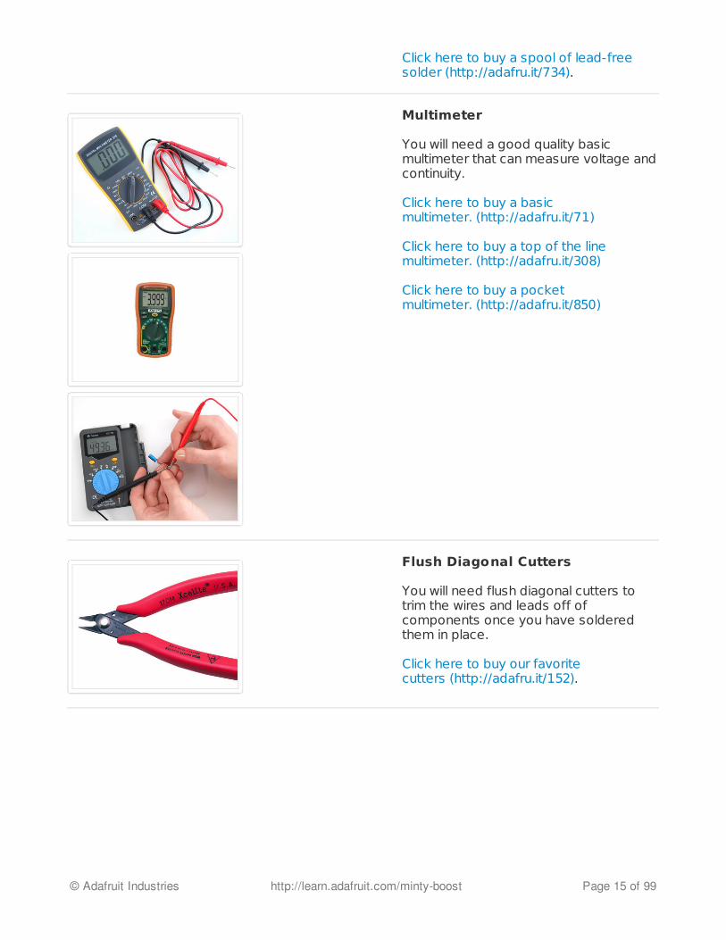
Click here to buy a spool of lead-freesolder (http://adafru.it/734).
Multimeter
You will need a good quality basicmultimeter that can measure voltage andcontinuity.
Click here to buy a basicmultimeter. (http://adafru.it/71)
Click here to buy a top of the linemultimeter. (http://adafru.it/308)
Click here to buy a pocketmultimeter. (http://adafru.it/850)
Flush Diagonal Cutters
You will need flush diagonal cutters totrim the wires and leads off ofcomponents once you have solderedthem in place.
Click here to buy our favoritecutters (http://adafru.it/152).
© Adafruit Industries http://learn.adafruit.com/minty-boost Page 15 of 99

Solder Sucker
Strangely enough, that's the technicalterm for this desoldering vacuum tool.Useful in cleaning up mistakes, everyelectrical engineer has one of these ontheir desk.
Click here to buy aone (http://adafru.it/148).
Helping Third Hand With Magnifier
Not absolutely necessary but will makethings go much much faster, and it willmake soldering much easier.
Pick one up here (http://adafru.it/291).
© Adafruit Industries http://learn.adafruit.com/minty-boost Page 16 of 99
Parts list
Check your kit!Check to make sure your kit comes with the following parts. Sometimes we make mistakes sodouble check everything and email [email protected] if you need replacements!
Note that the parts list is slightly different depending on whether it is the latestv3.0 kit, older v2.0 or ancient v1.2 kit. Check the kit packaging to determinewhich version you have! If you have an older version, scroll down to find yourparts list!
Also note that Altoids has discontinued their gum. We have identically sizedtins in the store now (http://adafru.it/16).
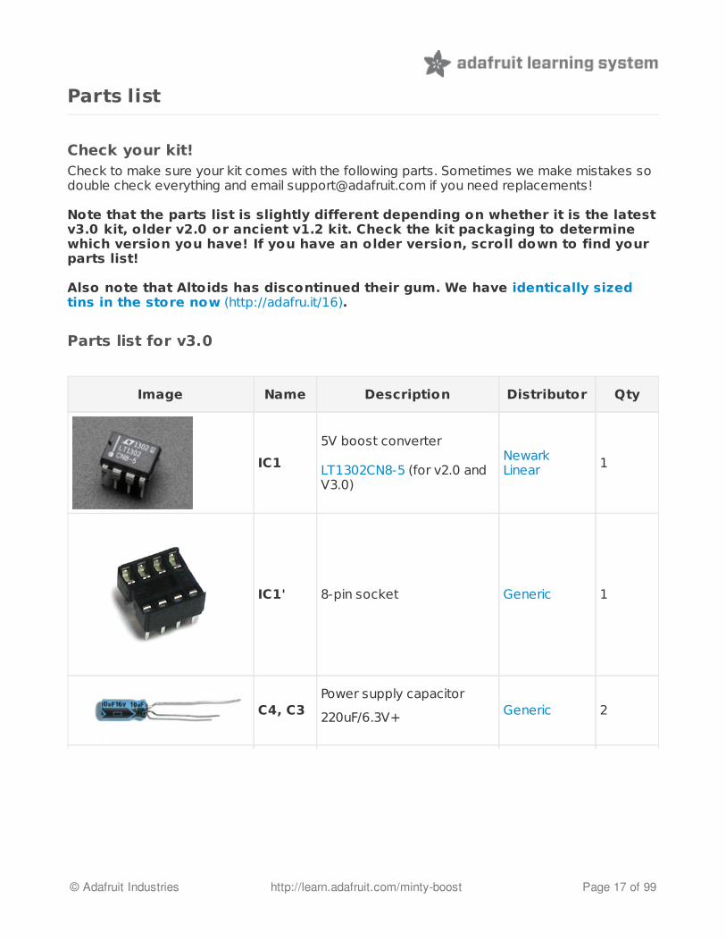
Parts list for v3.0
Image Name Description Distributor Qty
IC1
5V boost converter
LT1302CN8-5 (for v2.0 andV3.0)
NewarkLinear 1
IC1' 8-pin socket Generic 1
C4, C3Power supply capacitor
220uF/6.3V+ Generic 2
© Adafruit Industries http://learn.adafruit.com/minty-boost Page 17 of 99

C1, C2 Bypass capacitor (0.1uF) CeramicCapacitor 2
R5
1/8W 5% 3.3K resistorOrange Orange Red Gold
This part was added inversion 3.0. If youdon't have one youmay have a version 2.0kit!
Generic 1
R2, R4
1/8W 1% 75K resistorViolet Green Black RedBrown
This part may also appearas a Brown-body 7502FDALE resistor
This part was added inversion 3.0. If youdon't have one youmay have a version 2.0kit!
2
R1, R3
1/8W 1% 49.9K resistorYellow White White RedBrown
This part was added inversion 3.0. If youdon't have one youmay have a version 2.0kit!
2
D1 1N5818 (or 1N5817, etc)Schottky Diode 1N5818 1
© Adafruit Industries http://learn.adafruit.com/minty-boost Page 18 of 99

Schematic for v3.0
L1 10uH power inductor, atleast 1A current capability RLB9012-10 1
X1 USB type A female jack Generic 1
2 x AA battery holder Keystone2463 1
PCB Circuit board AdafruitIndustries 1
© Adafruit Industries http://learn.adafruit.com/minty-boost Page 19 of 99

Parts list for v2.0This kit version was discontinued August 2010 and replaced with version 3.0
Image Name Description Distributor Qty
IC15V boost converter
LT1302CN8-5 (for v2.0)
NewarkLinear 1
IC1' 8-pin socket Generic 1
C4, C3Power supply capacitor
220uF/6.3V+Generic 2
© Adafruit Industries http://learn.adafruit.com/minty-boost Page 20 of 99
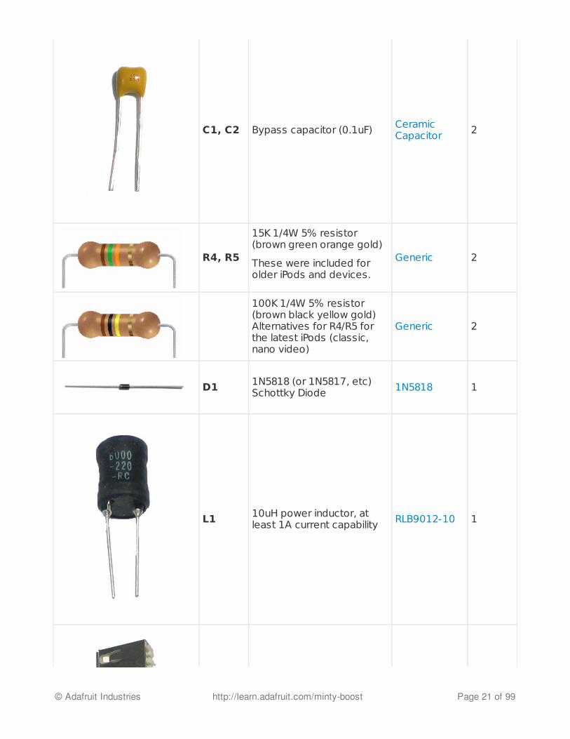
C1, C2 Bypass capacitor (0.1uF) CeramicCapacitor 2
R4, R5
15K 1/4W 5% resistor(brown green orange gold)
These were included forolder iPods and devices.
Generic 2
100K 1/4W 5% resistor(brown black yellow gold) Alternatives for R4/R5 forthe latest iPods (classic,nano video)
Generic 2
D1 1N5818 (or 1N5817, etc)Schottky Diode 1N5818 1
L1 10uH power inductor, atleast 1A current capability RLB9012-10 1
© Adafruit Industries http://learn.adafruit.com/minty-boost Page 21 of 99
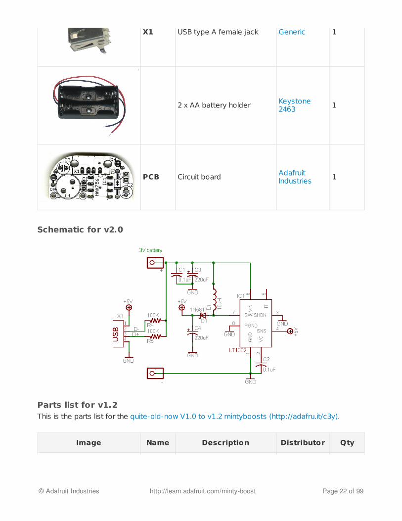
Schematic for v2.0
Parts list for v1.2This is the parts list for the quite-old-now V1.0 to v1.2 mintyboosts (http://adafru.it/c3y).
X1 USB type A female jack Generic 1
2 x AA battery holder Keystone2463 1
PCB Circuit board AdafruitIndustries 1
Image Name Description Distributor Qty
© Adafruit Industries http://learn.adafruit.com/minty-boost Page 22 of 99

IC15V boost converter
MAX756-CPA (for v1.2)
DigikeyMaxim 1
IC1' 8-pin socket Generic 1
C4, C3Power supply capacitor
100uF/6.3V or higher Generic 2
C1, C2 Bypass capacitor (0.1uF) CeramicCapacitor 2
R4, R5
15K 1/4W 5% resistor(brown green orange gold)
These were included forolder iPods and devices.
Generic 2
100K 1/4W 5% resistor(brown black yellow gold) Alternatives for R4/R5 forthe latest iPods (classic,nano video)
Generic 2
© Adafruit Industries http://learn.adafruit.com/minty-boost Page 23 of 99
Schematic for v1.2
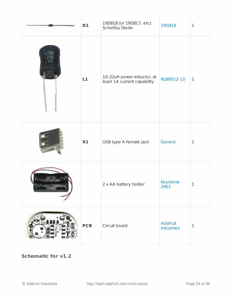
D1 1N5818 (or 1N5817, etc)Schottky Diode 1N5818 1
L1 10-22uH power inductor, atleast 1A current capability RLB9012-10 1
X1 USB type A female jack Generic 1
2 x AA battery holder Keystone2463 1
PCB Circuit board AdafruitIndustries 1
© Adafruit Industries http://learn.adafruit.com/minty-boost Page 24 of 99

LED1, R1, R2 and R3 are optional, not included in the kit, and should be installed only if the userwants the "Low Battery Indication" function. Check the MAX756 datasheet for information onhow to pick R1 and R2.
R5 should be installed as either a pulldown or pullup (like R4) - in the V1.2 pcb there are twopositions possible
Mintyboost® is a registered trademark of Adafruit Industries
© Adafruit Industries http://learn.adafruit.com/minty-boost Page 25 of 99

Solder it
Instructions for Version 3.0These are the instructions for v3.0 , if you have an older mintyboost you may want to check outthe specific instructions for earlier versions (http://adafru.it/c3z).
Solder It!The first step is to solder the kit together. If you've never soldered before, check thePreparation page for tutorials and more (http://adafru.it/c3s).
First! Check the Bill of Materials to verifyyou have all the parts necessary to makethe kit (http://adafru.it/c3t).
Most importantly, check which version ofthe kit you have. Look at the packaging,and the PCB - find that v3 thats on theback near the top!
Place the PCB in a vise, and turn on thesoldering iron. Make sure you have all thetools you'll need to assemble thekit (http://adafru.it/c3s).
If you don't know how to solder, wesuggest checking out the videos in thelink above. They're quite good! Keepthem in a window so you can watch andreview as you work through the kit
The first part we will place is the resistorR5 - this is a small oval tan thing with twowires (leads) and color stripes. Thestripes are orange orange red whichindicates a 3.3K resistor. This resistor isused to improve the high currentcapability of the boost converter chipand is a new addition to the mintyboost.The resistor goes right in the middle,over the silkscreen text that says R5.
Resistors are non-polar which meansthey don't have a direction: you don'thave to worry about putting it in'backwards' because they work the same
© Adafruit Industries http://learn.adafruit.com/minty-boost Page 26 of 99

either way.
Bend the resistor into a staple and slip itonto the top of the Printed Circuit Board.Bend the little leads out so that you canflip over the PCB and the resistor will stayin place.
Now you'll solder! Place the flat of thesoldering iron tip against the silver ring(pad) and one of the wires of the resistor(lead) at the same time for 2 seconds.This will heat them both up to 600-700degrees. Then poke the end of thesolder so that it flows into the hole andforms a solder joint.
Solder joints should be smooth and shinyand fill the entire pad, wicking up to thelead. You shouldn't be able to wiggle thewire and have it move in the hole.
© Adafruit Industries http://learn.adafruit.com/minty-boost Page 27 of 99

Now we will get rid of all that excess wire.Use your diagonal nippers to clip the wirejust above the end of the solder joint.There should be almost no 'wire' stickingout.
Next up we will solder in the 75K 1%resistors R2 and R4.
These resistors are blue and have thefollowing stripe colors: Violet GreenBlack Red Brown. They're very small andeasy to confuse with the other blueresistors, but the other resistors havewhite and yellow stripes so perhaps lookand make sure your resistors don't haveany light stripes on them?
You might also have brown 7502FDALE resistors that are a little larger, inthis case you can double the resistorover like this and solder it in the samespot. They wont sit flat but thats alright!
These resistors are used by AppleiPhones and such to determine what kindof charger isconnected (http://adafru.it/c3k).
© Adafruit Industries http://learn.adafruit.com/minty-boost Page 28 of 99

Solder the resistors as you did the 3.3Kone, one point at a time, checking yourwork.
Clip the long ends.
© Adafruit Industries http://learn.adafruit.com/minty-boost Page 29 of 99
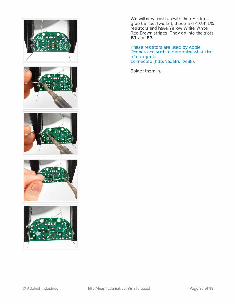
We will now finish up with the resistors.grab the last two left, these are 49.9K 1%resistors and have Yellow White WhiteRed Brown stripes. They go into the slotsR1 and R3.
These resistors are used by AppleiPhones and such to determine what kindof charger isconnected (http://adafru.it/c3k).
Solder them in.
© Adafruit Industries http://learn.adafruit.com/minty-boost Page 30 of 99
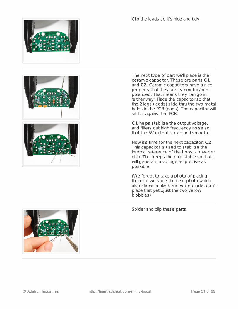
Clip the leads so it's nice and tidy.
The next type of part we'll place is theceramic capacitor. These are parts C1and C2. Ceramic capacitors have a niceproperty that they are symmetric/non-polarized. That means they can go in'either way'. Place the capacitor so thatthe 2 legs (leads) slide thru the two metalholes in the PCB (pads). The capacitor willsit flat against the PCB.
C1 helps stabilize the output voltage,and filters out high frequency noise sothat the 5V output is nice and smooth.
Now it's time for the next capacitor, C2.This capacitor is used to stabilize theinternal reference of the boost converterchip. This keeps the chip stable so that itwill generate a voltage as precise aspossible.
(We forgot to take a photo of placingthem so we stole the next photo whichalso shows a black and white diode, don'tplace that yet...just the two yellowblobbies)
Solder and clip these parts!
© Adafruit Industries http://learn.adafruit.com/minty-boost Page 31 of 99
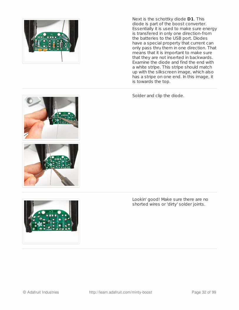
Next is the schottky diode D1. Thisdiode is part of the boost converter.Essentially it is used to make sure energyis transfered in only one direction-fromthe batteries to the USB port. Diodeshave a special property that current canonly pass thru them in one direction. Thatmeans that it is important to make surethat they are not inserted in backwards.Examine the diode and find the end witha white stripe. This stripe should matchup with the silkscreen image, which alsohas a stripe on one end. In this image, itis towards the top.
Solder and clip the diode.
Lookin' good! Make sure there are noshorted wires or 'dirty' solder joints.
© Adafruit Industries http://learn.adafruit.com/minty-boost Page 32 of 99
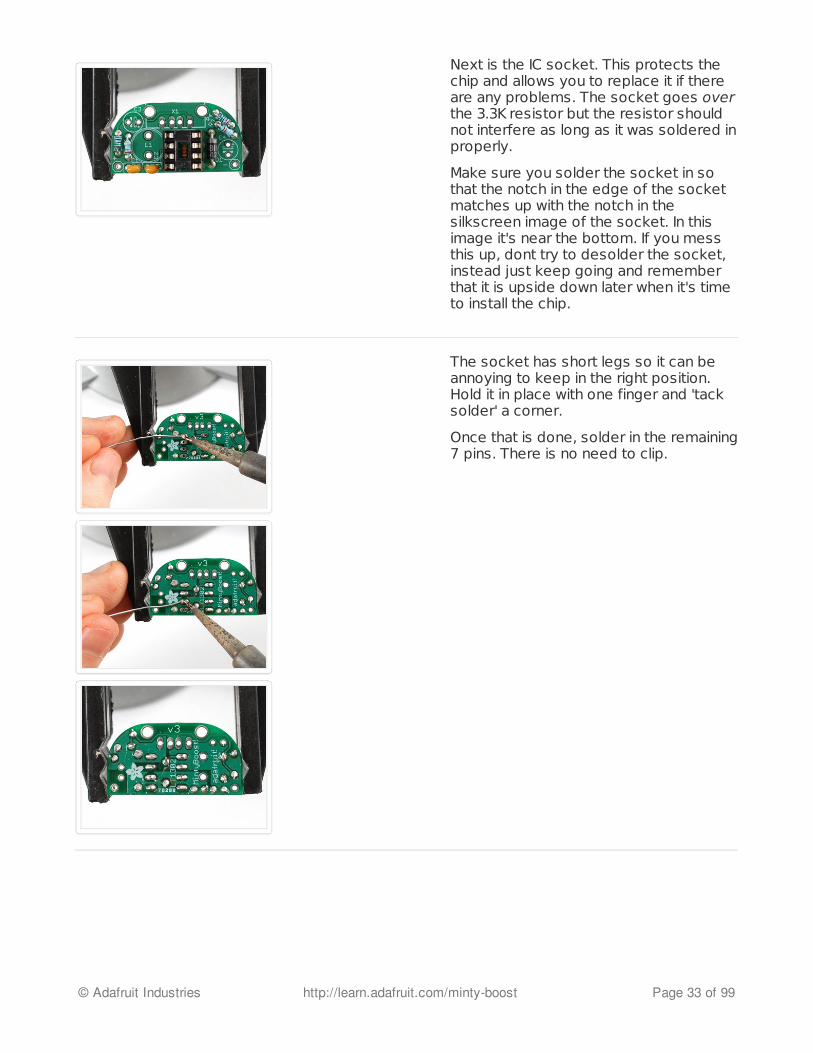
Next is the IC socket. This protects thechip and allows you to replace it if thereare any problems. The socket goes overthe 3.3K resistor but the resistor shouldnot interfere as long as it was soldered inproperly.
Make sure you solder the socket in sothat the notch in the edge of the socketmatches up with the notch in thesilkscreen image of the socket. In thisimage it's near the bottom. If you messthis up, dont try to desolder the socket,instead just keep going and rememberthat it is upside down later when it's timeto install the chip.
The socket has short legs so it can beannoying to keep in the right position.Hold it in place with one finger and 'tacksolder' a corner.
Once that is done, solder in the remaining7 pins. There is no need to clip.
© Adafruit Industries http://learn.adafruit.com/minty-boost Page 33 of 99
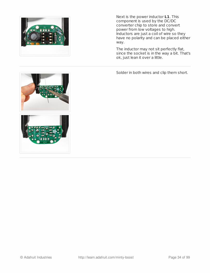
Next is the power inductor L1. Thiscomponent is used by the DC/DCconverter chip to store and convertpower from low voltages to high.Inductors are just a coil of wire so theyhave no polarity and can be placed eitherway.
The inductor may not sit perfectly flat,since the socket is in the way a bit. That'sok, just lean it over a little.
Solder in both wires and clip them short.
© Adafruit Industries http://learn.adafruit.com/minty-boost Page 34 of 99
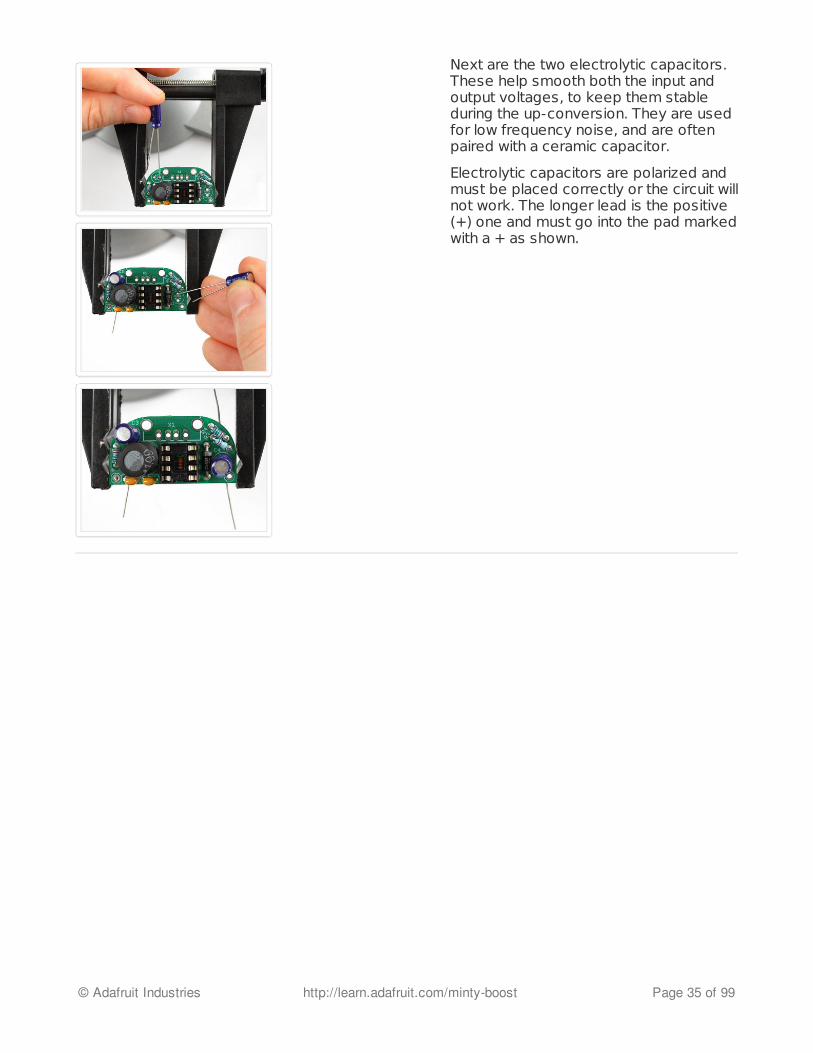
Next are the two electrolytic capacitors.These help smooth both the input andoutput voltages, to keep them stableduring the up-conversion. They are usedfor low frequency noise, and are oftenpaired with a ceramic capacitor.
Electrolytic capacitors are polarized andmust be placed correctly or the circuit willnot work. The longer lead is the positive(+) one and must go into the pad markedwith a + as shown.
© Adafruit Industries http://learn.adafruit.com/minty-boost Page 35 of 99

Solder in the two capacitors then clip thewires.
Next, solder in the 2xAA battery holder.The red wire goes to the hole marked +and the black wire goes to the holemarked -.
Make sure you have them in right or youcan damage the circuit!
© Adafruit Industries http://learn.adafruit.com/minty-boost Page 36 of 99
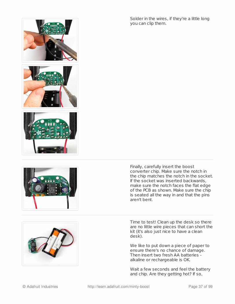
Solder in the wires, if they're a little longyou can clip them.
Finally, carefully insert the boostconverter chip. Make sure the notch inthe chip matches the notch in the socket.If the socket was inserted backwards,make sure the notch faces the flat edgeof the PCB as shown. Make sure the chipis seated all the way in and that the pinsaren't bent.
Time to test! Clean up the desk so thereare no little wire pieces that can short thekit (it's also just nice to have a cleandesk).
We like to put down a piece of paper toensure there's no chance of damage.Then insert two fresh AA batteries -alkaline or rechargeable is OK.
Wait a few seconds and feel the batteryand chip. Are they getting hot? If so,
© Adafruit Industries http://learn.adafruit.com/minty-boost Page 37 of 99

remove the batteries and look over yourwork. The kit should not even get warm!
Use your multimter (hey you know how touse a multimeter right? If not, please readour voltage tutorialhere (http://adafru.it/aZZ)) to measurethe voltage in the two outer pins of theUSB connector.
You should get a bit higher than 4.8V butlower than 5.2V.
If you get higher than 5.2V or lower than4.8V, first check that your multimeter hasa fresh battery. Really! this is a reallycommon problem!
If you get lower than 3V, remove thebatteries and check your work.
Next check between the rightmost pinand the second and third pin. Theyshould both be at just about 2.0V
Once you are happy with these tests,remove the batteries and finishassembling the kit!
Next is the USB type A connector. This isthe connector that is on a computer, andnearly all USB charging cables will pluginto it. The Connector should snap easilyin place.
© Adafruit Industries http://learn.adafruit.com/minty-boost Page 38 of 99
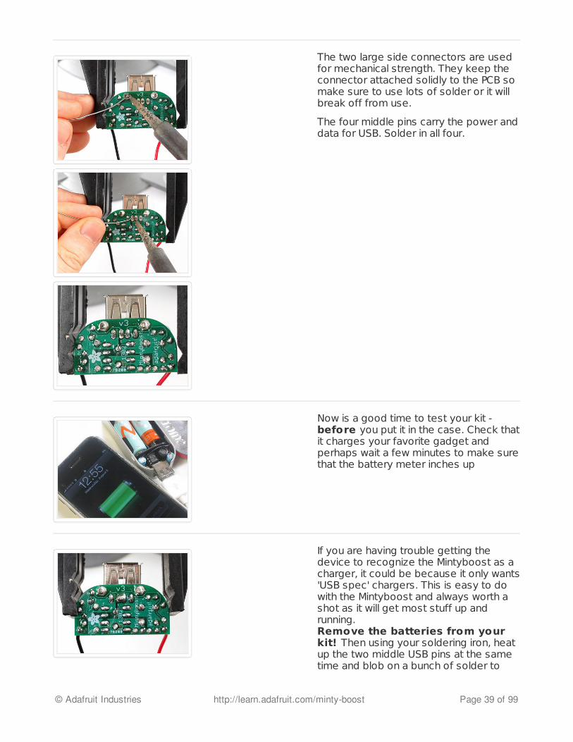
The two large side connectors are usedfor mechanical strength. They keep theconnector attached solidly to the PCB somake sure to use lots of solder or it willbreak off from use.
The four middle pins carry the power anddata for USB. Solder in all four.
Now is a good time to test your kit -before you put it in the case. Check thatit charges your favorite gadget andperhaps wait a few minutes to make surethat the battery meter inches up
If you are having trouble getting thedevice to recognize the Mintyboost as acharger, it could be because it only wants'USB spec' chargers. This is easy to dowith the Mintyboost and always worth ashot as it will get most stuff up andrunning.Remove the batteries from yourkit! Then using your soldering iron, heatup the two middle USB pins at the sametime and blob on a bunch of solder to
© Adafruit Industries http://learn.adafruit.com/minty-boost Page 39 of 99

short them together.
Now try again!
Mintyboost® is a registered trademark of Adafruit Industries
© Adafruit Industries http://learn.adafruit.com/minty-boost Page 40 of 99

Case it
OK, now you're ready to put it in the case. Go buy a tin of Altoid gum, and eat them or givethem to your friends. I think they're disgusting so don't send them to me.
You'll need the MintyBoost kit, an emptygum tin, a pair of tinsnips and two piecesof doublesided foam sticky tape (thetape is included in the kit).
Cut two notches in the end of the tin, justabout where the flat part ends and the tinstarts to round out.
Note that Altoids has discontinued the gum. Note that Altoids has discontinued the gum. However, we did manage to find aHowever, we did manage to find asource of gum-sized tins and we have them in the store (see the link to the right)source of gum-sized tins and we have them in the store (see the link to the right)
© Adafruit Industries http://learn.adafruit.com/minty-boost Page 41 of 99

Now you want to bend the flap back andforth to break it off, if you're careful youcan bend it in more than out which willmake it round into the tin, one less sharpedge.
© Adafruit Industries http://learn.adafruit.com/minty-boost Page 42 of 99

Try a test fit. Slide the board in first, thenfit the battery pack in. Don't put thebatteries in for this test! Thecircuit board could short againstthe tin and destroy the circuit!
Once you're happy, remove theelectronics and put the doublesidedsticky foamtape on both the circuit boardand the battery holder.
Remember to make sure no pin orparts or leads are sticking out andcan touch the tin.
Use duct, foam or, electrical tape toprotect the circuit. Clip your leads shortso they dont poke through the foam. Youcan easily destroy the circuit by beingsloppy here.
© Adafruit Industries http://learn.adafruit.com/minty-boost Page 43 of 99

You're done! Remember that becausethe boost chip uses virtually no power,you dont have to remove the batteries toturn off the MintyBoost. Just plug andunplug devices whenever you want.
Here is a hack that was sent in by KRHAiNOS, for making the mintyboost more sturdy, click tosee the large version of the image.
Mintyboost® is a registered trademark of Adafruit Industries
Enter a TitleEnter a Titlehttp://adafru.it/cJt
© Adafruit Industries http://learn.adafruit.com/minty-boost Page 44 of 99
Use it!
Tips and tricks, how to use your MintyBoost
The MintyBoost User manual!
How to use the Mintyboost (http://adafru.it/c3i)Batteries! How to get the most out of your mintyboost from picking the right AA's torechargables, to mega-capacity, and more! (http://adafru.it/c35)Compatibility list for the latest v3 Mintyboosts (http://adafru.it/c3A)Compatibility list for older v2.x Mintyboosts (http://adafru.it/c3B)The mysteries of Apple iDevice charging...revealed! (http://adafru.it/c3k)Changes between versions of the Mintyboost (http://adafru.it/c3y)
© Adafruit Industries http://learn.adafruit.com/minty-boost Page 45 of 99

How to use
Basic User Manual
Go MintyBoost!Here is a basic instructional manual that will cover pretty much everything you need to knowabout the mintyboost you just built.
CompatibilitySo, does it work with your gadget? First you can always visit our compatibility list which we keepupdated. We have a list for versions 2.x (http://adafru.it/c3B) of the kit and3.x (http://adafru.it/c3A). We try to keep the list updated as much as possible - if something isnot on that list then it doesn't mean it doesnt work, just that we dont know. Almost all devicescharge fine!
One thing you can always do is try it out! Wait until the battery is halfway drained, then plug yourgadget into the USB port and wait a few minutes and see if the battery inches up or if thecharging light goes on. You can also feel the mintyboost to see if it's warming up which wouldindicate it's providing power to the gadget.
Which batteries to use?Basically, get the best batteries you can. New Lithium or Alkaline 1.5V batteries work great asdo fully charged NiMH rechargables. Old, worn out or dead batteries will not work at all.
We have a very detailed tutorial about batteries in case you want a lot ofdetails (http://adafru.it/c35).
How to chargeEasy, get a USB charging cable for your gadget, nearly all come with one these days, you canalso usually get one for cell phones or games at an accessory shop. Plug in the USB end intoyour mintyboost and the other end into your device. That's it! The gadget will draw power tocharge up the battery.
While charging...While charging your device, you may notice the Mintyboost and batteries getting very hot. Thisis normal, it's because of how much power is being delivered to the gadget! The Mintyboost willcool down as soon as you unplug it. The maximum temperature for the mintyboost chip is over100 degrees C, that is hotter than boiling water. If you are worried, lick your finger (a little) andtouch the tip of your finger to the top of the LT1302 chip. If you don't hear a sizzle (of the waterboiling away), it's just fine.
If the mintyboost is getting really hot when it's not plugged in, there may be a short! Removethe batteries and check to make sure there is insulation between the mintyboost PCB and tin.
© Adafruit Industries http://learn.adafruit.com/minty-boost Page 46 of 99
You may also hear a 'hiss' or 'squeak' coming out of the chip. Sometimes the inductorresonates with the boost converter and that resonance leaks into the audible range. While it'snot good for it to always vibrate, it does happen rarely and is not harmful to the chargingdevice. You can try moving the inductor a little with your finger but the noise is electrical innature so it's hard to stop completely.
Another thing is that it depends on how much power the device is drawing and what kind ofbatteries are inside.
When to stop chargingThe mintyboost will charge and charge until the batteries give out and the voltage output isn't5V anymore. At this point the batteries are toast and you won't be able to squeeze any morepower out of them. However, some phones and mp3 players (especially ones that start with an'i') are not very smart and even if there is no more power coming out of the charger, they stayon, which means they slowly drain back down.
Basically, the best way to avoid this is to not leave the mintyboost plugged inovernight. Just charge for a few hours or while you're using it!
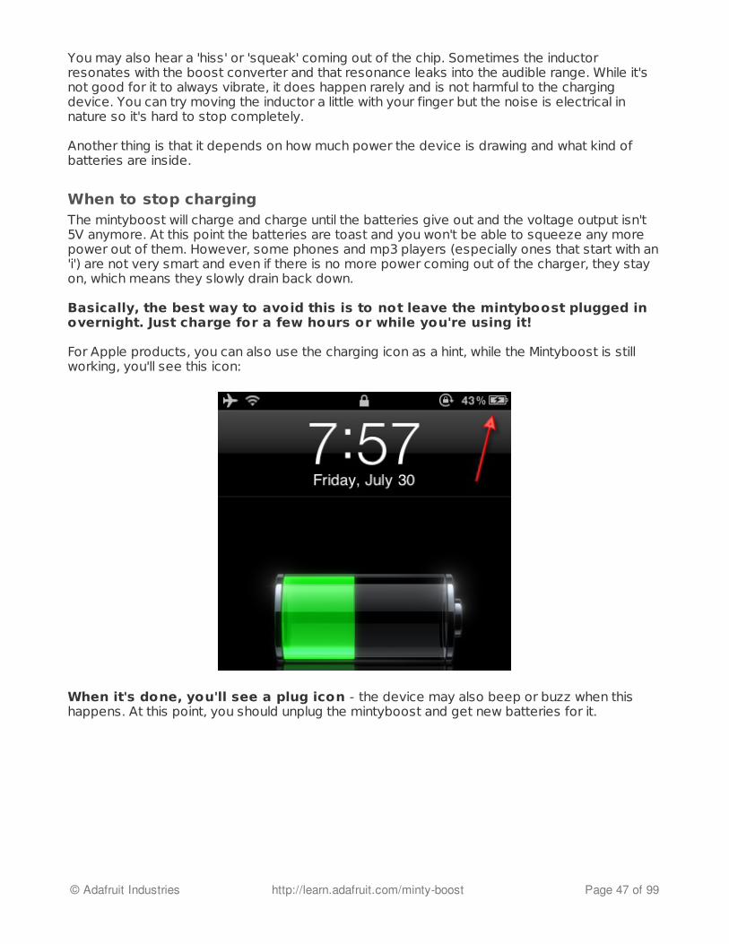
For Apple products, you can also use the charging icon as a hint, while the Mintyboost is stillworking, you'll see this icon:
When it's done, you'll see a plug icon - the device may also beep or buzz when thishappens. At this point, you should unplug the mintyboost and get new batteries for it.
© Adafruit Industries http://learn.adafruit.com/minty-boost Page 47 of 99

Batteries
User manual - Choosing batteries
Batteries?The most important part of using your Mintyboost is choosing and installing the right batteries.Poor quality batteries will cause frustration, and using the wrong kinds can damage your kit!
Please read this guide which will cover all the kinds of batteries you can use.
How the mintyboost worksThe mintyboost is a voltage source which means it tries its hardest to make sure the output isat 5 volts no matter what the current draw (by the target device) is. The device you arecharging (mp3 player, etc) is a resistive load. That means it basically sucks as much power as itwants out of the mintyboost.
The device you are charging is almost certainly very 'stupid' - it doesn't know or care that youare trying to use AA batteries to recharge it. Most devices assume that you are plugged intothe wall or into a computer (which is plugged into the wall) and suck as much power aspossible to quickly charge up so you can listen to music or make phone calls.
This, of course, is a bit of a tradeoff. The higher the current draw, the harder the mintyboosthas to work, and the AA's have to work. They'll get hot, they lose efficiency, the batteries drainand droop. There is no way for the mintyboost itself to fix this, it is completely up to the phoneor music player!
For that reason, we need to have good batteries, that will be able to work well while beingdrained fast!
Standard AA'sWe suggest using two AA batteries to run the Mintyboost - that's why we include a 2xAA holderin the kit! AA batteries are common and inexpensive and provide a good amount of voltageand current. (See below for detailed information about voltage and current guidelines)However, not all batteries are made the same! Picking the right kinds of batteries will give youthe best results.
In approximate order of effectiveness, here are the non-rechargable batteries you will want touse:
1. Lithium 1.5V 'high drain' AA batteries (2900 mAh)2. High quality (Duracell/Energizer) 'high drain' alkaline batteries3. High quality (Duracell/Energizer) alkaline batteries4. Non-brand Alkaline batteries5. Other kinds of non-rechargable AA batteries (zinc, etc)
© Adafruit Industries http://learn.adafruit.com/minty-boost Page 48 of 99
Higher quality batteries will give you longer boost times, cheap or deadbatteries are the leading cause of 'flaky' behavior so be sure to get goodbatteries.
Don't "mix" dead and non-dead cells, or different kinds of cells. If you buy 2 batteries in a pack,keep them together. This will get you the best performance.
Rechargable AA'sYou can use rechargable batteries in the Mintyboost, as well! Here in approximate order ofeffectiveness, are the non-rechargable batteries you will want to use:
1. High-capacity (~2500mAh), high quality NiMH batteries (See the standard in testing, theNiMH shootout (http://adafru.it/c3C)!)
2. Eneloop3. Non-brand medium capacity NiMH batteries (See the standard in testing, the NiMH
shootout (http://adafru.it/c3C)!)4. NiZn batteries (? We haven't actually tested these so we are not 100% sure if they perform
well but they should be OK)5. NiCad batteries
Good quality NiMH batteries work fantastic, but be careful of using really old cells. Don't "mix"dead and non-dead cells, or different kinds/brands of cells. If you buy 2 batteries in a pack,keep them together, and charge/use them at the same time. This will get you the bestperformance.
Alkaline or rechargable?Which is better? Well, that's a question that depends a lot on the battery quality. In general wealways suggest rechargables as they are less wasteful and are not much more expensive.However, sometimes you're in a bind or need the light weight of Lithium AA's. Either type will dofine, but try to stick to #1 thru #3 in the preferences above.
The tradeoffs are:
Alkaline batteries are available eveywhere, don't need to be charged before use, can beless expensiveAlkaline batteries have a higher 'nominal voltage' of 1.5V so they provide more power justbecause of the voltage increaseNiMH are very good at providing a lot of current, often better than Alkalines (althoughperhaps not as good as Lithium 1.5V cells)NiMH cells other than Eneloop and similar 'low self discharge' will slowly run down even whenjust sitting around
Because the run time completely depends on how the device charges, what its battery size is,etc, nothing beats timing and testing the first time you use the Mintyboost tocharge your device.
© Adafruit Industries http://learn.adafruit.com/minty-boost Page 49 of 99

Bigger batteries? More batteries?Let's say you want more power out of your mintyboost - the best way to do this is to upgradethe batteries from AA to something beefier!
Lets start with alkalines. Please refer to this Duracell alkaline battery capacity chart:
For example, upgrading a set of Duracell AA's (2850 mAh) to C (7800 mAh) or D cells (15000mAh!) will increase the capacity 3x (C) or 5.5x (D) !
If you want even MORE power, you can add a third battery in series to increase the inputvoltage from 3 volts (2 x 1.5v) to 4.5 volts. Three AA Alkaline batteries has approximately 1/3xmore power than 2 Alkaline AA's, three C's have 4x as much capacity as two AA's, and three D'shave 7.5x more capacity. ,br> However, there is a limit to how many more batteries you can add. For example, after 3Alkalines, one would think you should go for 4. But 4 Alkalines is 6V nominal (and actually maybe as high as 7V) - since this is higher than the 5V output, it is not safe or good for themintyboost or your device. For that reason, use only 2 or 3 alkaline batteries, not 4!
OK, now what about rechargable AA's? First thing to remember is that rechargables C or D cellsmay not have more capacity. Sometimes they are really AA batteries in a large plastic shell!Assuming that you can get real rechargable C or D cells, you should be able to get 3x or 5xmore capacity just by going with bigger batteries.
The other option is to add more batteries in series. You can definately go with three NiMH cells,which will boost power by 1/3 and as long as you are using NiMH/NiCad rechargableyou can also try 4 AAs. Because NiMH cells do not run at 1.5v (they run at 1.2v or so) fourcells will be under 5 volts. Of course, do not use 5 or 6 AA's as that will go well over the 5 voltlimit.
Lithium Ion PolymerIf you are an advanced electronics geek and want an ultra light rechargable mintyboost youmay be thinking about going with a lipoly or liion battery. The Mintyboost works great withthese, but be sure to watch for the following:
1. Use only single lithium ion polymer cells - 3.7 to 4.2v. Don't use 7.2v-8.4v cells! those areway too big.
2. Use only lithium ion/poly cell with a protection circuit. The mintyboost draws a lot of currentand will drain the battery all the way down, unprotected raw cells will almost certainly bedamaged, either bursting, catching on fire, leaking fluid, etc. Really, we mean it!
3. Use only a proper recharger for the cells, lithium ion/poly's are delicate and cannot becharged in a NiMH charge.
© Adafruit Industries http://learn.adafruit.com/minty-boost Page 50 of 99

4. Do not parallel lithium polymer cells on your own. Power packs come with a 'balancer' circuitthat must be used to keep them from discharging into each other.
Basically, don't start noodling around trying to invent your own lithium polymer cell pack!
How many recharges will I get?This completely depends on what kind of batteries are in the mintyboost and what kind ofbattery is in your device. Both are energy buckets, but the size of the buckets will tell you if youcan fill one with the other.
There are few things that make a difference:
The first thing to keep in mind is that the Mintyboost converts power from low voltage tohigh voltage (5V) but it is not perfect, there is charging efficiency loss. The conversionefficiency can be approximated as 80% - it may be higher or lower but it's prettyclose.The device battery capacity is mAh. (The mWh is not useful here, because thecharger inside is linear.) If your gadget has a 1000 mAh battery inside, that tells you the sizeof the bucket you are trying to fill.The mintyboost battery capacity. For fairly good batteries, this is going to be about2800 mAh.The fact that the most AA batteries you get have their capacity specified for low-drain useand this is high drain use. For alkalines you can probably consider the capacity to really onlybe 75% of what they say it is. For NiMH, maybe 80%, and for Lithium Polymer it's100% (they are really good at this sort of thing).The mintyboost battery voltage. For alkalines this is 1.5, for NiMH its going to be less,1.2V
Let's say we are using Duracell 1.5V Alkaline AA's.
First, figure out what the milliWatt-hours of the mintyboost power supply is:
mintyboost mWh = Battery voltage (V) * Battery capacity (mAh) * Capacityderating2 * 1.5V * 2850mA * 75% = 6400 mWh
This is the battery's capacity. Next we calculate the milliAmp hours the mintyboost will output at5V:
Output mAh @ 5V = Battery mWh (mWh)/ 5 (V) * Boost Efficiency6400 mWh / 5V * 80% = 1026 mAh output
This how much current it can provide, and for how long. Now divide this by the size of thebattery it's charging. Say you are charging an iPhone 3G (which has a 1200 mAh battery inside):
# of full recharges = MB output mAh /Device Battery Capacity
© Adafruit Industries http://learn.adafruit.com/minty-boost Page 51 of 99
1026mAh / 1200mAh = 0.85 times
So, at best, two Alkalines can get you about 85% charged up (not more than one charge!)
Lets try again with Sanyo AA NiMH 2700mAh (the best NiMH batteries there are):
MintyBoost mWh = 2 * 1.2V * 2700mAh * 80% = 5184 mWh inputOutput mAh @ 5V = 5184mWh / 5 * 80% = 830 mAh output# of iPhone 3G recharges = 830 mAh / 1200 mAh = 0.70
These batteries will give you 70% charge up. Less than Alkalines because the nominal voltage(1.2V) is less than Alkaline (1.5V)
Finally, lets do a 1200mAh lipoly battery with 3.7V nominal voltage:
MintyBoost mWh = 3.7V * 1200mAh * 100% = 4440 mWh inputOutput mAh @ 5V = 4440mWh / 5 * 80% = 710 mAh output# of iPhone 3G recharges = 830 mAh / 1200 mAh = 0.60
These batteries will give you 60% charge up on your iPhone.
Note that these calculations will give you a reasonable approximation and an upper bound. Asthe batteries age, their capacity decreases. The internal charger of whatever you're chargingmay also not be 100% efficient. Keep this in mind but don't be surprised if it's an 'upper limit.'
Detailed guidelines - Voltage RequirementsThe Mintyboost converts a low voltage to 5V USB standard. Because of this the first thing youmust be aware of is that you cannot put a higher than 5v battery on the inputs to the circuit. Ifyou do, it could damage the kit. So make sure your battery unput is always below 5V.Do not use 9V batteries under any circumstance!
Another important thing to realize is that the chip inside the MintyBoost also has a minimumvoltage requirement, which is 2V. So do not try to run it off of a single AA battery or similar.
Your best bet is to keep the battery input between 2V and 4.5V. Under 2V, the chip won'twork, above 4.5V the chip becomes less efficiant (for extremely technical reasons that wewon't go into right here) and above 5V it will not be able to keep the voltage at a steady 5V.
Detailed guidlines - Current RequirementsMany devices now charge at 500mA or higher rate, which translates into a 1000 mA draw fromthe batteries (because the voltage is boosted, the current is also boosted!) Getting batterieswith low internal resistance and high mAh capacity is key.
Try to aim for at least 2000mAh capacity of your 1.5v batteries. For Lithium ion/poly 3.7v cells,1000mA or higher is good as well. Larger capacity batteries also have a positive side effectthat they dont droop or sag as much under high loads and have lower internal resistance!
Tons of info!
© Adafruit Industries http://learn.adafruit.com/minty-boost Page 52 of 99

Sanyo NiMH and Eneloop capacity info (http://adafru.it/c3D)
© Adafruit Industries http://learn.adafruit.com/minty-boost Page 53 of 99

Compat v3
Device Compatibility list for v3
Verison 3 mintyboosts!This compatibility list is for the version 3.0 of the mintyboost, which uses the LT1302 chargerchip and has 4 resistors for improved iPhone compatibility. Basically, If you got it after August2010, it's probably v3 - but check the kit packaging to be sure!
The following tables contain the current known tested devices and results. We are prettysure that every device that worked with the MintyBoost v2 (http://adafru.it/c3B)will work with the v3 in addition to all the Apple devices. However, we don't ownevery gadget in the world (that would be neat but expensive!) so if you find a device thatworks, please let us know by contacting us (http://adafru.it/c3O), posting in theforums (http://adafru.it/forums) or sending Feedback. Thank you!!!
Apple Products
Product name Results Battery Size
iPhone 5, 5s and 5c Works
iPhone 4s Works
iPhone 4 Works 1400mAh
iPhone 3Gs Works with most 1200mAh
iPhone 3G Works 1200mAh
iPhone Works 1400mAh
iPod Video 5G Works 450-850mAh
iPod Nano 3G Works
iPod Nano 5G Works 220mAh
iPod Nano multi-touch Works
iPod Touch 3G Works
© Adafruit Industries http://learn.adafruit.com/minty-boost Page 54 of 99

HTC
LG
iPod Touch 4G Works
iPad Doesn't work 6800mAh
Product name Results Battery Size Notes
T-Mobile G1 (Google DevPhone 1, HTC Dream) Works 1150 mAh
HTC Droid Eris Works
HTC Legend Works with v2 1300mAh
HTC Magic Works V3.0
HTC One S Works V3.0
HTC Desire A8183 Works 1400mAh
HTC Evo Works 1500mAh
HTC Droid Incredible Works V3.0
T-Mobile G2 (HTC Vision,HTC Desire Z) Works 1500mAh Detects as "USB Charger"
(Trickle charger)
HTC Hero GSM Works 1350 mAh
T-Mobile MyTouch 4G Works 1400 mAh
HTC Thunderbolt 4G(Verizon)
Works V3.0 -USB Spec 1400 mAh ~600 mA charging with 3
NiMH cells
HTC Velocity 4G (Telstra) Works 2 x Sanyo AAeneloops
Product name Results Battery Size Notes
LG Ally Works 1500mAhWill light up and claim to be charging,but won't actually charge without thedata lines shorted.
© Adafruit Industries http://learn.adafruit.com/minty-boost Page 55 of 99
Motorola
Samsung
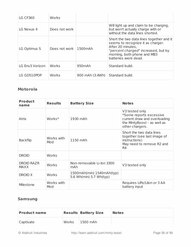
LG CF360 Works
LG Nexus 4 Does not workWill light up and claim to be charging,but won't actually charge with orwithout the data lines shorted.
LG Optimus S Does not work 1500mAh
Short the two data lines together and itseems to recognize it as charger.After 20 minutes,"percent charged" increased, but bymorning, both phone and MB3batteries were dead.
LG Env3 Verizon Works 950mAh Standard build.
LG GD510POP Works 900 mAh (3.4Wh) Standard build.
Productname Results Battery Size Notes
Atrix Works* 1930 mAh
V3 tested only*Some reports excessivecurrent draw and overloadingthe MintyBoost - as well asother chargers.
Backflip Works withMod 1150 mAh
Short the two data linestogether (see last image ofinstructions) May need to remove R2 andR4
DROID Works
DROID RAZRMAXX Works Non-removable Li-Ion 3300
mAh V3 tested only
DROID X Works 1500mAh(min) 1540mAh(typ)5.6 Wh(min) 5.7 Wh(typ)
Milestone Works withMod
Requires LiPo/LiIon or 3 AAbattery input
Product name Results Battery Size Notes
Captivate Works 1500 mAh
© Adafruit Industries http://learn.adafruit.com/minty-boost Page 56 of 99

Sony Ericsson
Nokia
RIM
Vibrant Works 1500 mAh
Moment Works
Galaxy S2 16GB GT-I9100 Works 1650 mAh
Galaxy S3 Works 7.98 wH 3.8 VLiIon
Tested v3 - no need to short datalines
Galaxy S3 i747 AT&T WorksWould claim to charge with standardbuild, but had to short data lines forit to work. CM10 ROM
Samsung Galaxy I7500 Works 1440 mAh
Samsung Galaxy Nexus Works 1850 mAh Tested v3
Product name Results Battery Size Notes
W580i Does not work 930mAh
V3 detected as PC, also after blobbingtogether the middle USB pins. Chargingshown on screen only when phoneswitched to PC (flash storage, offline)mode. But after 3 hours no change inbattery status. 2X2300 NiMH AA used,1.32V on each also after 3 hours
Xperia Arc Works 1500 mAh
Xperia Ray Works 1500 mAh
Product name Results Battery Size Notes
N97 Works 1200mAh Modified a v2 kit to V3 now charges fine
lumia 820 Works 1650mAh v3 kit-data terminals not shorted
© Adafruit Industries http://learn.adafruit.com/minty-boost Page 57 of 99
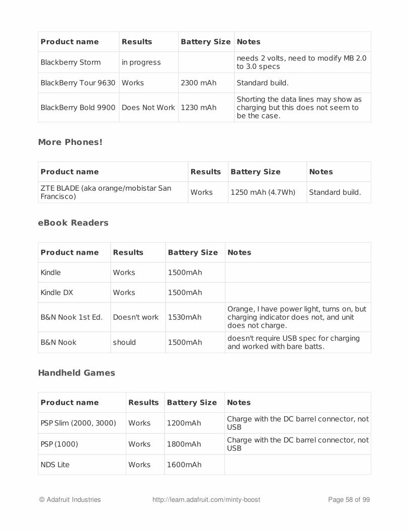
More Phones!
eBook Readers
Handheld Games
Product name Results Battery Size Notes
Blackberry Storm in progress needs 2 volts, need to modify MB 2.0to 3.0 specs
BlackBerry Tour 9630 Works 2300 mAh Standard build.
BlackBerry Bold 9900 Does Not Work 1230 mAhShorting the data lines may show ascharging but this does not seem tobe the case.
Product name Results Battery Size Notes
ZTE BLADE (aka orange/mobistar SanFrancisco) Works 1250 mAh (4.7Wh) Standard build.
Product name Results Battery Size Notes
Kindle Works 1500mAh
Kindle DX Works 1500mAh
B&N Nook 1st Ed. Doesn't work 1530mAhOrange, I have power light, turns on, butcharging indicator does not, and unitdoes not charge.
B&N Nook should 1500mAh doesn't require USB spec for chargingand worked with bare batts.
Product name Results Battery Size Notes
PSP Slim (2000, 3000) Works 1200mAh Charge with the DC barrel connector, notUSB
PSP (1000) Works 1800mAh Charge with the DC barrel connector, notUSB
NDS Lite Works 1600mAh
© Adafruit Industries http://learn.adafruit.com/minty-boost Page 58 of 99

MP3 Player
Product name Results Battery Size Notes
Zune HD Works 660mAh
© Adafruit Industries http://learn.adafruit.com/minty-boost Page 59 of 99
Compat v2
Device Compatibility for v2.x Mintyboosts
For version 2.x only!This compatibility list is for the v2 of the mintyboost, which uses the LT1302 charger chip butdoes not have the special iPhoney resistors. Basically, if you got it before August 2010, it'sdefinately v2 or earlier.
Mintyboost Compatibility chart!Turns out some devices don't like being charged with a battery pack, usually devices thatrequire special drivers to charge. (Try plugging it into a random computer's USB port, if youneed to install software to get it to start charging, you probably won't be successful.) Pleasepost on the forum if you have more information on what works and doesn't! Thanks
Tested Works:
Apple iPod: Mini, Nano rev 1G/2G/3G, Shuffle 1G/2G, Photo/5G/Video/ClassicRead Apple's identification guide (http://adafru.it/c3E) to see which one you've got, if you'renot sure.Older Apple iPod Touch (v1), iPhone and iPhone 3G (with v2.0 of the kit) - These do work,but they're finicky. Check the FAQ and try 'Lithium 1.5V' batteries. Unfortunately Applehas made updates to the firmware and hardware to make it harder forpeople to use "nonauthorized chargers." This has been fixed in v3 of theMintyboost.Arcos 605 WiFiAT&T 8525 (a.k.a. HTC Hermes).AudioVox 6700 (use R5 as a pullup)BlackberryBT-1 (http://adafru.it/c3F) bluetooth cameraCowon iAudio X5Creative Zen Micro (tested with firmware v1.11.01)Creative Zen Vision M (Doesn't work through USB but does work with a DCconnector/adaptor, as sold in the webshop (http://adafru.it/23))Dell DJ DittyGarmin Edge 305Garmin Forerunner 305 (unplug it when its done charging or it can drain itself!)Gigabeat S30 (Doesn't work thru USB but does work with a DC connector/adaptor, as sold inthe webshop (http://adafru.it/23))GlobalSat's DG-100 GPS dataloggerHOLUX GPSlim236 bluetooth GPSiMate Jam, iMate SP5 smartphone
© Adafruit Industries http://learn.adafruit.com/minty-boost Page 60 of 99

iMate Jam, iMate SP5 smartphoneiPaq (5555 pocket pc)iRiver Clix u10iRiver E10 (use pulldown)iRiver H340 (http://adafru.it/c3G)Locosys Technologies BGT-11 GPSLG enV2, VX9100M-AUDIO Microtrack 24/96Microsoft ZuneMobiBLU DAH-1500iMotorola QuanitcoMrobe 500 + 100 (with adaptor cable (http://adafru.it/23))Nintendo DS/GameBoy Advance (with adaptor cable (http://adafru.it/22))Nokia phones, using cables CA-70 and CA-100 will charge nearly all Nokia phones (exceptthe 8600), also known as 'standard Nokia USB data/charger' cablesO2 XDA II (http://adafru.it/22)Openmoko neo FreeRunner (see here (http://adafru.it/c3H))Palm TX, Palm Tungsten T3, Palm Zire 71 and 72, Palm PrePocketPC HX4700 (Go into the power settings and turn on charging through USB)Rio CarbonSamsung SCH-i730, SGH-i750, SGH-i858 (With a USB charger cable (http://adafru.it/c3I), youcan also hack a cable yourself, see here (http://adafru.it/c3J)) SCH-U520Samsung T809Sandisk Sansa Express (use pullup resistor) See notes here (http://adafru.it/c3K)Sony PSP (with adaptor cable (http://adafru.it/23))Treo 700p, 750 (using Palm's charge/sync cable)T-Mobile Dash (HTC Excalibur)T-Mobile Wing (or HTC Herald, or HTC P4350)T-Mobile G1 (google phone)
Tested Kinda Works:
Motorola RAZR v3: doesn't work by default, requires a bit of cable hacking. See thisdocument at pinouts.ru (http://adafru.it/c3L) and this fellow's graphic (http://adafru.it/c3M).Treo 600 (Says it isnt, but is. Won't charge more than 50% ?)Samsung D00 phone (Should also work: D800, D820, E780, E870, P300, P910, P920, T809,Z540) requires a cable hack (http://adafru.it/c3N)Motorola H700 bluetooth headset (Kinda? Sorta? Unclear)BT-GPS1210 (SIRF III mouse) requires USB charging cable
Tested Doesn't work:
Audiovox SMT 5600 Window Mobile phone (v1.2 works with the 6700 so it could be that thisworks now)1-3G iPods (Firewire only!)iPhone 3GS, 4, iPod Touch v2 and other 2010+ iPhones. This has been fixed in v3 ofthe Mintyboost
© Adafruit Industries http://learn.adafruit.com/minty-boost Page 61 of 99

Sidekick LX2009 (one report)MuVo Slim (one report)Sony EBook readerMotorola Q (one report)Nokia 8600 phones require a driver to charge, so are unlikely to work.
© Adafruit Industries http://learn.adafruit.com/minty-boost Page 62 of 99

Process
How to: How to
Meta DocumentationThis page details how I went through the process of coming up with the idea, hardware, design,etc. for this project. It's not 100% correct but it's pretty close. Since this project only took 2days (on & off) to design/test/release, it's a lot easier to keep track of than somethingenormous like the x0xb0x (http://adafru.it/c46).
This tutorial is quite old and the Mintyboost has gone thru many revisions sincethen (http://adafru.it/c3y). We suggest that after you read this you go on to read our "AppleCharging Secrets" tutorial which will take you from v1 (here) to the latestv3 (http://adafru.it/c3k).
Original IdeaOK so where does an idea come from anyways? It's the only important question & the mostdifficult. I guess I'd have to say it was prompted by looking at these half-dozen projects:
Aaron Dunlaps (http://adafru.it/c48) 9V USB chargerAnother 9V + 7805 USB charger (http://adafru.it/c49) (Instructables)Jason Streigel's 9V+7805 USB 'battery' (http://adafru.it/c4a) (hackaday)Ians Firewire switching charger (http://adafru.it/c4b) (Instructables (http://adafru.it/c4b))Chris DiClerico's 9V+AA's firewire charger (http://adafru.it/c4c)
OK, there's probably even some I'm missing. So what's the overarching theme here? Almost alluse 9V batteries and a 7805 (an extremely common linear 5V regulator: makes a solid 5V from7-18V input). This design works great because, well, 7805's are awesome and 9V's provide 7-9V depending upon how 'dead' they are.
However, there's one thing about 9V's that I've learned (from lots of bad experiences). One isthat they don't have a lot of amp-hours: that is, how much current (amps) they can provide andfor how long (hours). A duracell 9V provides -about- 500mAh over its lifetime. That's 500 mA(or .5A) for one hour or 100mA for 5 hours. That number is somewhat idealized but it's a goodstarting point.
Another problem is that they don't like to supply a lot of current, because they have highinternal resistance (~2ohms), but basically that just means that if you want a lot of current (sayto resuscitate a drained device) the 9V wont provide all 500mAh, but maybe more like 400.(Say you're drawing 250mA, then .25A*2ohm = 0.5V lost to internal resistance. For more info on9V, read the duracell datasheet (http://adafru.it/c4d).)
Another problem with the 9V+7805 scheme is that a 7805 is a linear regulator. That means ifyou want 100mA at 5V (basically, USB power) then you're taking 100mA at 9V and then losingthe 4V*100mA = 400mW (.4W) difference as heat.As the battery wears down to 7V the heat loss goes down to (7-5V)*100mA=.2W but you'restill getting bad efficiency. At best the efficiency is 72% (5V/7V) and at worst it's 55% (5V/9V)
© Adafruit Industries http://learn.adafruit.com/minty-boost Page 63 of 99

That means you're losing about a third of the battery power to heat!
I'll also throw out that the 7805 itself has a quiescent current of about 5mA so you're alwayslosing 5% (5mA/100mA) efficiency just for regulation! (& that's at least since if you're tricklecharging the battery at 50mA then the 5mA quiescent is 10%)
OK so basically the 7805+9V solution works but the efficiency is startlinglylow, say 60% or so, and provides only 300mAh at 5V.
We can engineer better!
Engineering better!From experience, I know that AA's are great. They are cheap, have lots of power, very lowinternal resistance and are easily available everywhere. Whereas a 9V has 500mAh (for a totalof 9*500 = 4.5Wh power) two AA's have 3000mAh each for a total of 2 * 1.5V * 3000mAh =9Wh, about twice as much power. The only problem is that 2xAA's provide 3V and what weneed is 5V. With a 9V battery we can use a linear regulator because 5V < 9V but, sadly, wecant use a linear regulator to turn 3V into 5V. Instead we will need to use a boost regulator (alsoknown as a DC/DC switching/step-up regulator).
The process of how a boost regulator works is somewhat beyond the scope of this document,suffice to say they work great but are a little more annoying than linear regulators because youhave to pick out an inductor and wire up some extra parts. You can get a lot more info aboutBoost Converters at wikipedia (http://adafru.it/c1g).
Case in pointSo at this point I start thinking about enclosure and size. Most people think of this last, andthat's a bad idea. If there's one thing I've learned from hacking on electronics, it's that youshould try and select the case first because it dictates a lot of the electronics and interface.
I know that the parts for the kit must be all through-hole (no surface mount) and easy to workwith. I also want AA batteries, 2 is good although I know from experience that most boostconverters will work with any number from 1 and 3 just fine. I have a predilection for Altoids tinsand I also know that I can fit ~2 AA's into a gum tin so I pull out a tin and take somemeasurements:
© Adafruit Industries http://learn.adafruit.com/minty-boost Page 64 of 99
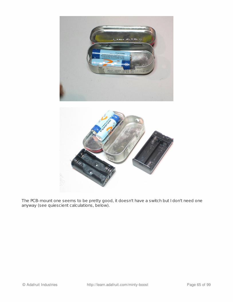
The PCB-mount one seems to be pretty good, it doesn't have a switch but I don't need oneanyway (see quiescient calculations, below).
© Adafruit Industries http://learn.adafruit.com/minty-boost Page 65 of 99

So I take some measurements...
© Adafruit Industries http://learn.adafruit.com/minty-boost Page 66 of 99

Looks like I have about 1.25" x 0.7" semicircular PCB space at the top for the circuit board.
I also try out another battery holder I have, this gives me more space, 1.25"x0.85"...but thebatteries go in sideways so one would have to remove the holder to change the batteries. I'dprefer that you can just take them out directly, so I don't go with this one (it also turns out Idon't need that extra space).
I now do a little hack to turn the PCB mount 2xAA battery holder into a wire-lead one. Like thisproduct photo (for "HOLDER BATTERY 2CELL AA 6"LEAD" from Digikey).
© Adafruit Industries http://learn.adafruit.com/minty-boost Page 67 of 99
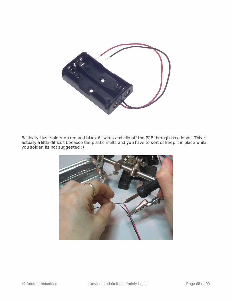
Basically I just solder on red and black 6" wires and clip off the PCB through-hole leads. This isactually a little difficult because the plastic melts and you have to sort of keep it in place whileyou solder. Its not suggested :)
© Adafruit Industries http://learn.adafruit.com/minty-boost Page 68 of 99
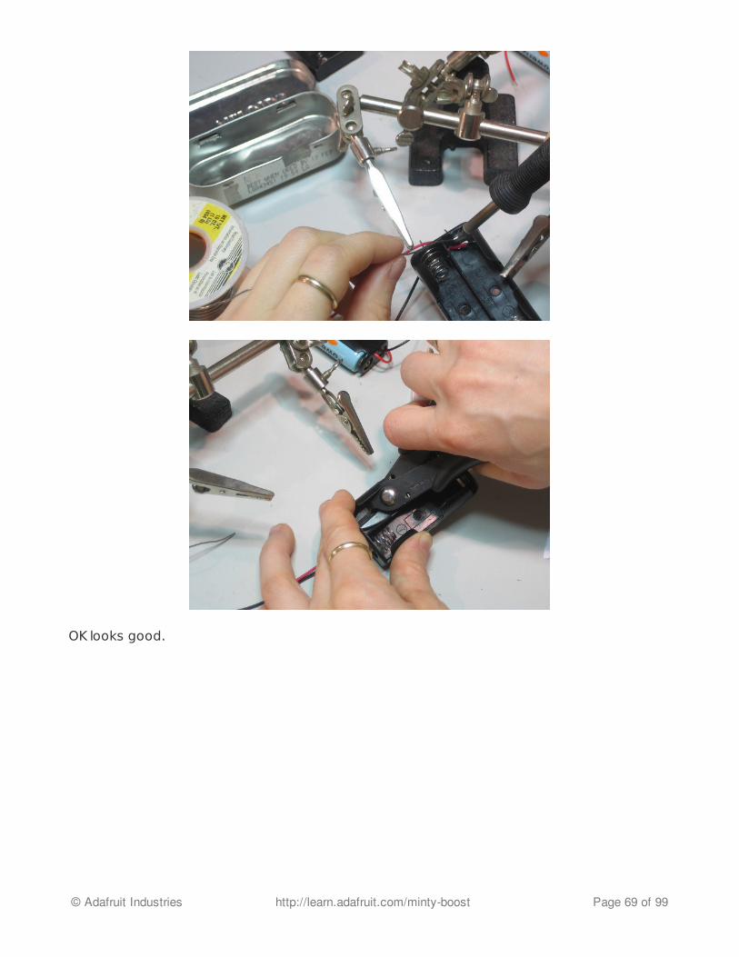
OK looks good.
© Adafruit Industries http://learn.adafruit.com/minty-boost Page 69 of 99

Now that's done I'm ready to think about what I can cram into that space.
Basic BoostSo now it's time to design the boost supply. Since I don't have much space, I'm going to try tomake my circuit as tiny as possible but still be easy to solder. That means I want a boost chipthat is 8-DIP (smallest though-hole), with an internal MOSFET switch (1 less part) and is highfrequency (to keep the inductor small). I also need to be able to supply 100mA at 5V and itshould run on as low as 2V input. Also I want to be able to buy it online from a common supplier.
1. 8-DIP package2. Internal FET switch3. 100mA output @ 5V4. 2V minimum input voltage
OK, lets search Digikey. I start with "DC/DC converter 8-DIP" and check "items in stock."
I then select 1 output, 8-DIP (to differentiate between 18-DIP) and select all the current-outputs>=100mA and apply the filter. There's still about 40 options. So then I select the all voltageinput ranges that start with 2V or less. Also I select all the Adjustable, and 5V-inclusive output
© Adafruit Industries http://learn.adafruit.com/minty-boost Page 70 of 99
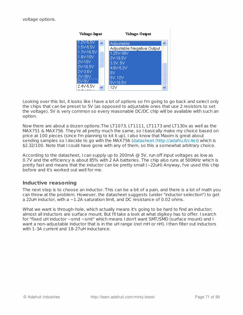
voltage options.
Looking over this list, it looks like I have a lot of options so I'm going to go back and select onlythe chips that can be preset to 5V (as opposed to adjustable ones that use 2 resistors to setthe voltage). 5V is very common so every reasonable DC/DC chip will be available with such anoption.
Now there are about a dozen options.The LT1073, LT1111, LT1173 and LT130x as well as theMAX751 & MAX756. They're all pretty much the same, so I basically make my choice based onprice at 100 pieces (since I'm planning to kit it up). I also know that Maxim is great aboutsending samples so I decide to go with the MAX756 (datasheet (http://adafru.it/c4e)) which is$2.32/100. Note that I could have gone with any of them, so this a somewhat arbitrary choice.
According to the datasheet, I can supply up to 200mA @ 5V, run off input voltages as low as0.7V and the efficiency is about 85% with 2 AA batteries. The chip also runs at 500KHz which ispretty fast and means that the inductor can be pretty small (~22uH) Anyway, I've used this chipbefore and it's worked out well for me.
Inductive reasoningThe next step is to choose an inductor. This can be a bit of a pain, and there is a lot of math youcan throw at the problem. However, the datasheet suggests (under "inductor selection") to geta 22uH inductor, with a ~1.2A saturation limit, and DC resistance of 0.02 ohms.
What we want is through-hole, which actually means it's going to be hard to find an inductor;almost all inductors are surface mount. But I'll take a look at what digikey has to offer. I searchfor "fixed uH inductor ~smd ~smt" which means I don't want SMT/SMD (surface mount) and Iwant a non-adjustable inductor that is in the uH range (not mH or nH). I then filter out inductorswith 1-3A current and 18-27uH inductance.
© Adafruit Industries http://learn.adafruit.com/minty-boost Page 71 of 99

That filters it down to about a dozen choices. The SLF inductor is actually surface mount, andwe're going to outright ignore the ones that cost more than $2.50. Inductors for smallelectronics like this should cost around $1-$2, as a guideline. That leaves us with the DN7418-ND "INDUCTOR 27UH POWER AXIAL" and the 6000-220K-RC "INDUCTOR HI CURRENT RADIAL22UH." Both of these look good, with about ~1.5A saturation current and 0.07 ohm DCresistance.
I also check out Mouser (http://adafru.it/c4f). The online search for mouser isn't as nice asDigikey's so I end up looking at the paper catalog instead. I only found one inductor, really, the18R223C (22uH radial power inductor) and/or the 18223C (axial version) that also has plenty ofpower capacity and a 0.03ohm DC resistance.
So, order 2 of each of these.
Rapid prototyping #1In reality, what I did was look through the Digikey catalog, where I only found the DN7418inductor (the other one was somewhat hidden in the RF inductor section). And it showed upbefore the Mouser box, so I spent an hour or two making up a prototype.
The circuit itself is simple, I want one large electrolytic cap for low frequency smoothing on thebattery, and an output cap pair (electrolytic and one ceramic cap for high freq. smoothing). Ialso need the chip, a reference voltage capacitor, the inductor and a schottky diode to finishoff the boost regulator. I happen to have some 1N5818's, which are often used as schottkydiodes in boost regulators. I also need a USB type A female jack, of course, and two holes tosolder the battery pack into.
© Adafruit Industries http://learn.adafruit.com/minty-boost Page 72 of 99

All these parts must fit into the space left over from the battery pack. I make EagleCAD libraryparts for the inductor and chip (the rest are already there) and lay out the board. I'm not goingto detail making library parts in eagle or pcb layout, others have done so already. Usewhichever software you want, I like Eagle because there's a free version available for downloadif you're just making small PCBs.
Since I am know this is just a prototype version, I make the PCB single sided -- for easy etching.I also make the traces really large.
I print out a paper version of the PCB and punch the parts through to verify that they're the rightshape/package.
© Adafruit Industries http://learn.adafruit.com/minty-boost Page 73 of 99

I get my etching setup together, turn on the heater for the etching tank, and print out a bunch oftiled PCB layouts on toner transfer. I transfer the toner onto a single sided PCB and etch it in thetank.
© Adafruit Industries http://learn.adafruit.com/minty-boost Page 74 of 99
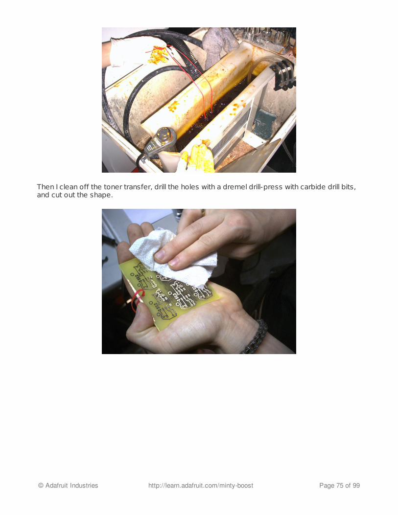
Then I clean off the toner transfer, drill the holes with a dremel drill-press with carbide drill bits,and cut out the shape.
© Adafruit Industries http://learn.adafruit.com/minty-boost Page 75 of 99

Then I solder the parts in, and fit it into the case with the battery pack, using double-sided foamsticky tape to hold down both the battery holder and the PCB without shorting the PCB to themetal tin.
© Adafruit Industries http://learn.adafruit.com/minty-boost Page 76 of 99

© Adafruit Industries http://learn.adafruit.com/minty-boost Page 77 of 99

Done!
Testing the prototypeNow we test to see if it works! With the two batteries inside, I measure the voltage on the USBconnector: about 5V, which is good. I send off this version to a friend with once of each kind ofiPod, including the newest 4G video iPod, for real-world testing: Both to verify the iPod willcharge and also how long it will run with the additional pack.
© Adafruit Industries http://learn.adafruit.com/minty-boost Page 78 of 99
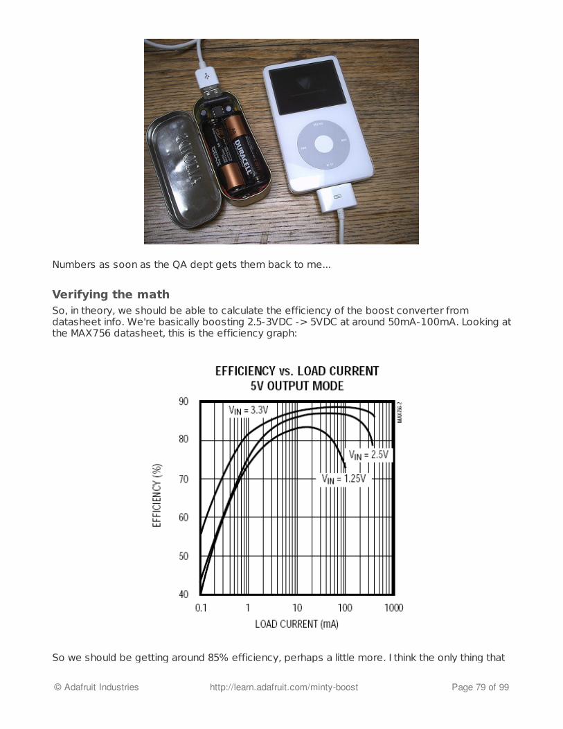
Numbers as soon as the QA dept gets them back to me...
Verifying the mathSo, in theory, we should be able to calculate the efficiency of the boost converter fromdatasheet info. We're basically boosting 2.5-3VDC -> 5VDC at around 50mA-100mA. Looking atthe MAX756 datasheet, this is the efficiency graph:
So we should be getting around 85% efficiency, perhaps a little more. I think the only thing that
© Adafruit Industries http://learn.adafruit.com/minty-boost Page 79 of 99

So we should be getting around 85% efficiency, perhaps a little more. I think the only thing thatcan really change this number a bit is the inductor. (Below, I verify I'm getting 82% efficiency)
If we're getting 82% efficiency conversion from 2 x 3000mAh Duracells, that means we get (2 *1.5V) * 3000mAh * .83 = 7.38 Watt hours. Compare that to a single 9V as we calculatedbefore: (1 x 9V) * 500mAh * .65 = 2.93 Wh. So we're going to get about 2.5x more power outof these two AAs than a single 9V. With rechargeable batteries, we get (2 * 1.25) * 2200mAh *81% = 4.45 Wh (about 50% more than an alkaline 9V and 3x more than a rechargeable 9V)
Next, lets verify the efficiency using test equipment, and try out the different inductors to see ifthey make a difference. Instead of using batteries, I'll provide 3V from a bench supply that willalso tell me how much current is being drawn. And instead of an iPod I'll fake the load with aresistor. Since the standard USB current draw is 100mA from 5V, that means I need a 5V/.1A =50 ohm load. I can't just use a tiny resistor because 5V * .1A = 1/2W and most resistors are1/4W. So instead I take two large 100ohm 'power' resistors, and twist them together. I alsocheck the resistance to verify that together they are 50ohms. I also find a 20ohm powerresistor. This will allow me to not only test a 100mA load but also a 250mA load.
I perform 4 tests with 2 inductors: 100mA load for both 2.5V in and 3V in (rechargeable anddisposable batteries) and 250 load for both. All the images are up on Flickr for viewing, here isone example one...inductor #1 (DN2474) with 100mA load and 2.5Vin.
Here are my results, summarized:
DN2474 100mA/3Vin 100mA/2.5Vin 250mA/3Vin 250mA/2.5Vin
Vout 5.01 4.93 4.77 4.62
Iout (calc'd) 100mA 99mA 234mA 231mA
Iin 200mA 245mA 530mA 690mA
Efficiency 83% 80% 70% 62%
© Adafruit Industries http://learn.adafruit.com/minty-boost Page 80 of 99
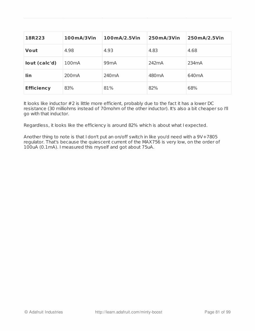
It looks like inductor #2 is little more efficient, probably due to the fact it has a lower DCresistance (30 milliohms instead of 70mohm of the other inductor). It's also a bit cheaper so I'llgo with that inductor.
Regardless, it looks like the efficiency is around 82% which is about what I expected.
Another thing to note is that I don't put an on/off switch in like you'd need with a 9V+7805regulator. That's because the quiescent current of the MAX756 is very low, on the order of100uA (0.1mA). I measured this myself and got about 75uA.
18R223 100mA/3Vin 100mA/2.5Vin 250mA/3Vin 250mA/2.5Vin
Vout 4.98 4.93 4.83 4.68
Iout (calc'd) 100mA 99mA 242mA 234mA
Iin 200mA 240mA 480mA 640mA
Efficiency 83% 81% 82% 68%
© Adafruit Industries http://learn.adafruit.com/minty-boost Page 81 of 99
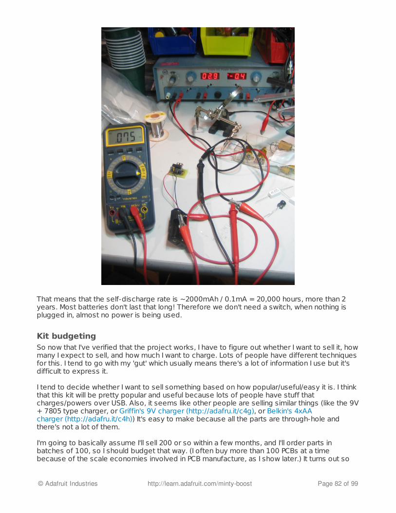
That means that the self-discharge rate is ~2000mAh / 0.1mA = 20,000 hours, more than 2years. Most batteries don't last that long! Therefore we don't need a switch, when nothing isplugged in, almost no power is being used.
Kit budgetingSo now that I've verified that the project works, I have to figure out whether I want to sell it, howmany I expect to sell, and how much I want to charge. Lots of people have different techniquesfor this. I tend to go with my 'gut' which usually means there's a lot of information I use but it'sdifficult to express it.
I tend to decide whether I want to sell something based on how popular/useful/easy it is. I thinkthat this kit will be pretty popular and useful because lots of people have stuff thatcharges/powers over USB. Also, it seems like other people are selling similar things (like the 9V+ 7805 type charger, or Griffin's 9V charger (http://adafru.it/c4g), or Belkin's 4xAAcharger (http://adafru.it/c4h)) It's easy to make because all the parts are through-hole andthere's not a lot of them.
I'm going to basically assume I'll sell 200 or so within a few months, and I'll order parts inbatches of 100, so I should budget that way. (I often buy more than 100 PCBs at a timebecause of the scale economies involved in PCB manufacture, as I show later.) It turns out so
© Adafruit Industries http://learn.adafruit.com/minty-boost Page 82 of 99

far that I can sell a couple hundred units of a kit in a few months, particularly if it gets picked upby a blog or web site. This may or may not be true for you, however if you can't afford to make25 kits at once you're going to find that it's hard to make any money in the process.
To figure out how much to charge, I make up a table with different quantity prices:
To calculate the PCB costs, I used Advanced Circuit's (http://adafru.it/c4i) insta-quote service:
Part Price / 1 Price / 50 Price / 100
Boost chip MAX756 $4.62 $2.79 $2.32
2 x 0.1uF caps $0.10 $0.10 $0.10
1n5818 diode $0.09 $0.09 $0.08
2 x 100uF caps $0.12 $0.10 $0.10
18R223 inductor $1.42 $1.35 $1.29
USB jack $0.52 $0.35 $0.32
AA holder $0.59 $0.53 $0.49
PCB ~$12.50? $7.25 $3.75
PCB tooling N/A $3 $1.5
Antistatic Bag N/A $0.12 $0.12
Sticky tape squares N/A $0.10 $0.10
Total $19.90 $15.75 $10.10
© Adafruit Industries http://learn.adafruit.com/minty-boost Page 83 of 99
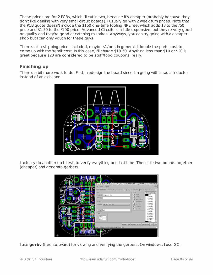
These prices are for 2 PCBs, which I'll cut in two, because it's cheaper (probably because theydon't like dealing with very small circuit boards). I usually go with 2 week turn prices. Note thatthe PCB quote doesn't include the $150 one-time tooling NRE fee, which adds $3 to the /50price and $1.50 to the /100 price. Advanced Circuits is a little expensive, but they're very goodon quality and they're good at catching mistakes. Anyways, you can try going with a cheapershop but I can only vouch for these guys.
There's also shipping prices included, maybe $1/per. In general, I double the parts cost tocome up with the 'retail' cost. In this case, I'll charge $19.50. Anything less than $10 or $20 isgreat because $20 are considered to be stuff/food coupons, really.
Finishing upThere's a bit more work to do. First, I redesign the board since I'm going with a radial inductorinstead of an axial one:
I actually do another etch test, to verify eveything one last time. Then I tile two boards together(cheaper) and generate gerbers.
I use gerbv (free software) for viewing and verifying the gerbers. On windows, I use GC-
© Adafruit Industries http://learn.adafruit.com/minty-boost Page 84 of 99

prevue.
I always check the boards with www.freedfm.com (http://adafru.it/c4j) before I ship them off tobe made. I used 4pcb.com so it's the same company but even if you don't go with 4pcb.com asyour PCB manufacturer, it's a neat service.
A week later (depending on your turn time) A box shows up with the circuit boards!
© Adafruit Industries http://learn.adafruit.com/minty-boost Page 85 of 99

Then I sit in front of a computer and do a lot of website stuff. I also take a lot of photos. A goodphoto setup will make documentation easy. I have a simple 150W ECT bulb + diffuser setup atEYEBEAM. A tripod is key!
© Adafruit Industries http://learn.adafruit.com/minty-boost Page 86 of 99

Mintyboost® is a registered trademark of Adafruit Industries
© Adafruit Industries http://learn.adafruit.com/minty-boost Page 87 of 99
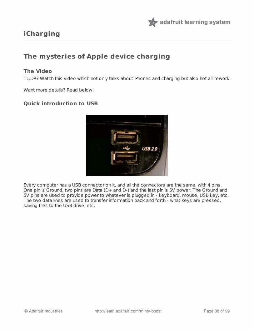
iCharging
The mysteries of Apple device charging
The VideoTL;DR? Watch this video which not only talks about iPhones and charging but also hot air rework.
Want more details? Read below!
Quick introduction to USB
Every computer has a USB connector on it, and all the connectors are the same, with 4 pins.One pin is Ground, two pins are Data (D+ and D-) and the last pin is 5V power. The Ground and5V pins are used to provide power to whatever is plugged in - keyboard, mouse, USB key, etc.The two data lines are used to transfer information back and forth - what keys are pressed,saving files to the USB drive, etc.
© Adafruit Industries http://learn.adafruit.com/minty-boost Page 88 of 99

Shown above, the 4 wires. Red is power, black is ground, and the white and green wires are thedata lines.
Using USB as a power supplySome inexpensive USB toys (say a USB fan or mini soda cooler (http://adafru.it/c3Q)) don'thave any data transfer, they just suck the power from the USB port to run. In this case, they donot use or connect to the Data pins (they are left to 'float').
Now technically USB ports can provide up to 500mA of current output, and technicallyevery device is supposed to perform a basic data transfer to the computer (calledenumeration) where it says "hey, I'm about to drag 500mA out of the computer, just so youknow" and the computer can say "go ahead" or "no can do" (this is called the powernegotiation).
However, we've found that every device that does not require to do any data transfer (say,USB fans or USB battery chargers) don't bother to warn the computer and just go ahead andgrab up to (or even more!) than 500mA from the USB port. As long as they aren't going thru anunpowered hub, this seems to be just fine. All computers have a resettable fuse on the USBport so that if more than 1000mA is drawn, the power will be disconnected. This protectsagainst short circuits in your $5 USB fan that would take down the entire computer!
iCharge!Knowing the above, we designed the first Mintyboost to not have anything on the data lines -we assumed that nearly every charger and device would just ignore those pins as they tendnot to be used
For example, in the CAD file of the first Mintyboost, the USB connector is the top square. Thefour ovalish pins in row as the USB wires. Pin #1 and #4 are used for power (blue lines areconnected) but there are no traces on the middle two data pins - they are floating.
© Adafruit Industries http://learn.adafruit.com/minty-boost Page 89 of 99
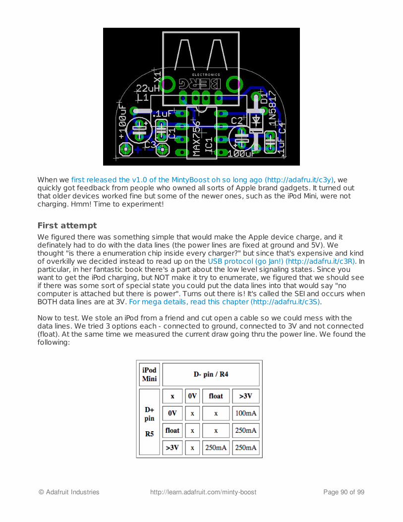
When we first released the v1.0 of the MintyBoost oh so long ago (http://adafru.it/c3y), wequickly got feedback from people who owned all sorts of Apple brand gadgets. It turned outthat older devices worked fine but some of the newer ones, such as the iPod Mini, were notcharging. Hmm! Time to experiment!
First attemptWe figured there was something simple that would make the Apple device charge, and itdefinately had to do with the data lines (the power lines are fixed at ground and 5V). Wethought "is there a enumeration chip inside every charger?" but since that's expensive and kindof overkilly we decided instead to read up on the USB protocol (go Jan!) (http://adafru.it/c3R). Inparticular, in her fantastic book there's a part about the low level signaling states. Since youwant to get the iPod charging, but NOT make it try to enumerate, we figured that we should seeif there was some sort of special state you could put the data lines into that would say "nocomputer is attached but there is power". Turns out there is! It's called the SEI and occurs whenBOTH data lines are at 3V. For mega details, read this chapter (http://adafru.it/c3S).
Now to test. We stole an iPod from a friend and cut open a cable so we could mess with thedata lines. We tried 3 options each - connected to ground, connected to 3V and not connected(float). At the same time we measured the current draw going thru the power line. We found thefollowing:
© Adafruit Industries http://learn.adafruit.com/minty-boost Page 90 of 99

OK, so yes when the pins are floating no charging occurs. The next thing to note is that whetherthe pins are pulled up or down effects the current draw. Since this was the first Mintyboost,using the MAX756, we wanted to use the lower 100mA rate so one pin pulled down andanother pulled up. This would be more efficient for the battery use and keep the chip fromgetting hot (it could provide 250mA but didn't like it much).
Thus was born Mintyboost v1.1!
Note that because the mintyboost runs from 2 AA batteries, we can get 3V directly from thebatteries so we connected the pullup right to the battery input.
The iPhone and larger iPodsThis worked ok for about a year, then people starting getting the newer iPods and noticed thatthe Mintyboost didn't work anymore.
More testing!
© Adafruit Industries http://learn.adafruit.com/minty-boost Page 91 of 99

Hmm, looks like we need to have two pull ups after all. We made a new version that now hadeither a pulldown or pullup on the D+ line.
iPhonesThis worked for a bit until the iPhones came out. With enormous batteries, the iPhone was nothappy charging at 250mA - it wanted 500mA or even 1000mA to charge! We sought out anupgrade to the MAX756 and found the LT1302 which could provide 500mA no problem.
© Adafruit Industries http://learn.adafruit.com/minty-boost Page 92 of 99
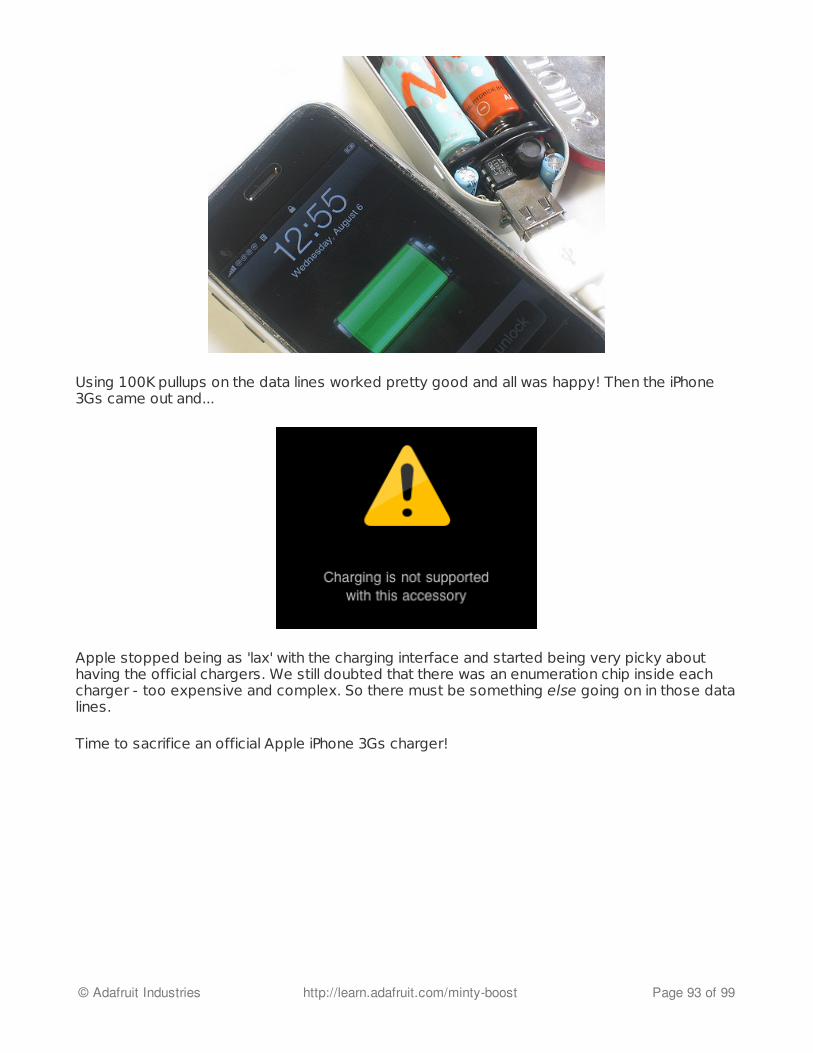
Using 100K pullups on the data lines worked pretty good and all was happy! Then the iPhone3Gs came out and...
Apple stopped being as 'lax' with the charging interface and started being very picky abouthaving the official chargers. We still doubted that there was an enumeration chip inside eachcharger - too expensive and complex. So there must be something else going on in those datalines.
Time to sacrifice an official Apple iPhone 3Gs charger!
© Adafruit Industries http://learn.adafruit.com/minty-boost Page 93 of 99

Taking it apart, desoldering the 4 data line resistors and measuring them on our multimeter, wefound the following as shown in the schematic:
The four resistors create a voltage at each of the data lines that's not 3.3V but rather 2.8 and2.0 (or so) volts. The problem is that when you do this, the iPhone starts to draw as much as1Amp! Way more than the LT1302 and a couple AA's can provide. We were a bit sad andthought that there was no way to get the Mintyboost working with an iPhone when we took attrip to J&R and found an item called the TuneJuice. The TuneJuice is an iPhone charger that uses4 AAA batteries. This is very interesting because there is no way to get an Amp out of AAA's -they are just way too small. That means there must be something ELSE going on in thatTuneJuice charger to keep the iPhone from gobbling up the batteries. So we took apart thecharger!
© Adafruit Industries http://learn.adafruit.com/minty-boost Page 94 of 99
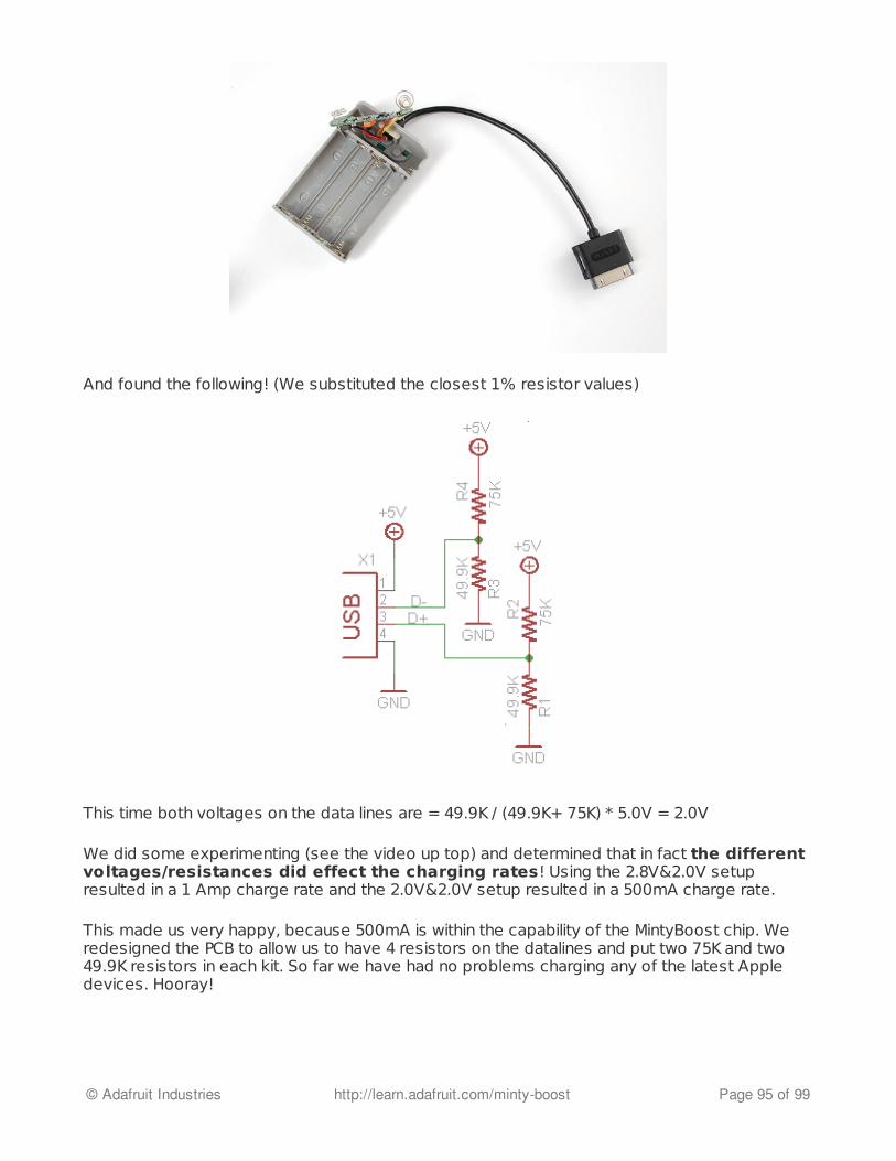
And found the following! (We substituted the closest 1% resistor values)
This time both voltages on the data lines are = 49.9K / (49.9K+ 75K) * 5.0V = 2.0V
We did some experimenting (see the video up top) and determined that in fact the differentvoltages/resistances did effect the charging rates! Using the 2.8V&2.0V setupresulted in a 1 Amp charge rate and the 2.0V&2.0V setup resulted in a 500mA charge rate.
This made us very happy, because 500mA is within the capability of the MintyBoost chip. Weredesigned the PCB to allow us to have 4 resistors on the datalines and put two 75K and two49.9K resistors in each kit. So far we have had no problems charging any of the latest Appledevices. Hooray!
© Adafruit Industries http://learn.adafruit.com/minty-boost Page 95 of 99

Change Log
What's changed?
A long history of boostingThe mintyboost is one of our oldest projects, and has evolved to work with more and moreproducts. Here are the differences between the many versions!
V1.0 - June 2006 (first release)(Schematic is essentially the same as the v1.1 but without R4 and R5)
Documented in the process page, this kit used the MAX756 boost chip fromMaxim (http://adafru.it/c3T), and could provide about 100-150mA output at 5V. There were nodata line resistors for pulling up or down but it worked with most things.
v1.1 - July 2006
After a few months it became clear that some devices especially Apple music players, neededpullup/down resistors, so a new version that could fit 1 pullup and 1 pulldown was designed.This version still used the MAX756 (http://adafru.it/c3T).
v1.2 - April 2007(Schematic is essentially the same as the v1.1 but with an additional resistor slot from D- toground)
Turns out that some devices wanted two pullups on either data pin, so version 1.2 had an
© Adafruit Industries http://learn.adafruit.com/minty-boost Page 96 of 99
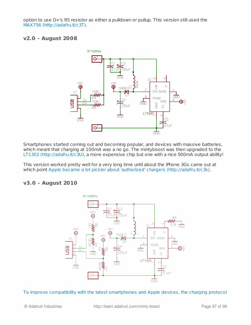
option to use D+'s R5 resistor as either a pulldown or pullup. This version still used theMAX756 (http://adafru.it/c3T).
v2.0 - August 2008
Smartphones started coming out and becoming popular, and devices with massive batteries,which meant that charging at 100mA was a no go. The mintyboost was then upgraded to theLT1302 (http://adafru.it/c3U), a more expensive chip but one with a nice 500mA output ability!
This version worked pretty well for a very long time until about the iPhone 3Gs came out atwhich point Apple became a lot pickier about 'authorized' chargers (http://adafru.it/c3k).
v3.0 - August 2010
To improve compatibility with the latest smartphones and Apple devices, the charging protocol
© Adafruit Industries http://learn.adafruit.com/minty-boost Page 97 of 99

was reverse engineered so that the Mintyboost would be more universal. The pullup/down pinswere also changed a full resistive divider which made it work with LiPoly batteries and Appledevices (http://adafru.it/c3k). Still uses a LT1302 chip.
A 3.3K pulldown R5 was also added to turn off low-power 'boost mode' in the LT1302 chip, thisimproved high-drain handling at the risk of lower efficiency at low current draw. However, at thispoint, almost all devices have large batteries (> 500mAh) and require high charge rates.
© Adafruit Industries http://learn.adafruit.com/minty-boost Page 98 of 99

Download
Downloads
v2.0 files
v2.0 Schematic in PNG (http://adafru.it/cn1)v2.0 Schematic (http://adafru.it/cn2) and Board layout (http://adafru.it/cn3) files in EagleCADformat
All of these files are available under the Creative Commons (http://adafru.it/c37) 2.5 attributionlicense.
v1.0, v1.1 and v1.2 filesYou can use these files with the DN2474 inductor, it's single-sided so it's easy to etch at home.You can generate Gerbers or extract a postscript image (for toner transfer) easily, usingEagleCAD (http://adafru.it/c3Y), freely available for Mac/Win/Linux.
Prototype schematic (http://adafru.it/cn4) and board (http://adafru.it/cn5) files
Here are the final files, for the kit. They use a radial inductor and have pads for a low batteryindicator SMT LED. It's doublesided but there's only one trace to jumper if you're not using thelow battery indicator.
V1.0 schematic (http://adafru.it/cn6) and board (http://adafru.it/cn7) files
I then did a minor upgrade to add a pullup and pulldown for better performance:
V1.1 schematic (http://adafru.it/cn8) and board (http://adafru.it/cn9) files
All of these files are available under the Creative Commons (http://adafru.it/c37) 2.5 attributionlicense.
Datasheets
LT1302 (http://adafru.it/c3U) pageMAX756 (http://adafru.it/c3T) datasheetAA NiMH (http://adafru.it/c45) datasheet
© Adafruit Industries Last Updated: 2013-12-09 01:30:54 PM EST Page 99 of 99