Passive Undulatory Gaits Enhance Walking in a Myriapod ... · Passive undulatory gaits enhance...
8
Passive undulatory gaits enhance walking in a myriapod millirobot Katie L. Hoffman and Robert J. Wood Abstract— The design and modeling of a segmented myriapod millirobot with a compliant body is presented. A dynamic model is used to demonstrate how body undulations can result from only varying the phase difference in the stance change between adjacent segments - even with passive intersegmental connections - and how these gaits affect locomotion. Different gaits are demonstrated experimentally in a 20-leg, 2.2 gram millirobot, and the resulting motion is compared to that predicted by the simulation. Both simulation and experiments show that undulatory gaits can increase the average speed of straight-line locomotion as compared to non-undulatory gaits for the same stepping frequency. The model and the millirobot can be used concurrently with biological studies to understand aspects of myriapod locomotion. This robot is also a useful tool to gain insight into how flexibility can be introduced into robots at this scale to enhance locomotion. I. INTRODUCTION In recent years, biological inspiration has accelerated the development of aerial, ambulatory, and aquatic robots. At the insect scale, these include ambulatory robots such as Dy- naRoACH, a 24 gram autonomous hexapod [1], HAMR, a 2 gram hexapod capable of speeds up to 4 body lengths/second [2], and DASH, a robust and agile 10 cm long hexapod [3]. The design of these millirobots was inspired by cockroaches who are among the fastest creatures on the planet (normal- ized to body length) at up to 40 body lengths/second [4]. Due to the relatively low number of articulated components and a nominally rigid body, it is natural to use these insects as inspiration for ambulatory robots. However, the diversity of body morphologies found in nature leaves open questions about ambulation at small scales. For example, why do arthropods have different numbers of legs? Why do some creatures have flexible bodies while others have rigid bodies with flexible appendages? How do passive dynamics affect walking? This paper looks to explore some of these questions using a centipede-inspired robot. Although their bodies are much more elongated, cen- tipedes are also agile creatures with maximum speeds around 10 body lengths per second [5]. The flexibility inherent in myriapods allows them to morph to surfaces and smoothly transition between horizontal and vertical surfaces. This flex- ibility also has the potential to enhance locomotion through the use of body undulations and enable rapid turns. The segmented nature of a centipede body suggests a modular design, which can be adapted for use in different situations. A many-legged robot could also be robust to leg failures, still capable of locomotion even after the loss of multiple The authors are with the School of Engineering and Applied Sciences and the Wyss Institute for Biologically Inspired Engineering, Harvard University, Cambridge, MA 02138 [email protected] legs, as is the case with actual centipedes. Increased static stability could result from the added number of legs on the ground at any time, and the center of mass is likely to always remain within the support tripod since more legs are distributed along the length of the body. While additional legs may increase the total number of components of the robot, due to the use of repeating segments, the number of unique components would not increase. The concurrent development of batch fabrication techniques for millirobots could allow centipede robots at this scale to be easily fabricated. Fig. 1. Photo of a 10-segment, 20-leg centipede-inspired millirobot. The effectiveness of undulatory gaits, or the wavelike motion of the body as depicted in Fig. 2(a), demonstrated by many centipedes have long been debated by biologists. Manton, who did visual studies on centipede locomotion and body morphology in the 1950’s argued that the undulations were passive. At low speeds, these undulations were less pronounced as compared to when the same specimen were traveling at higher speeds [5]. This led her to the conclusion that at low speeds the centipedes were able to suppress any body waves that would naturally arise, whereas when moving faster, the centipedes were unable to actively work against the undulations. Conversely, while using both visual information as well as electromyograms attached to the lateral flexor muscles situated along the body of a centipede, Anderson found that centipedes actively promote body undulations [6]. Groups of legs form pivot points along the length of the body, which curves around the points (Fig. 2(a)). This body rotation may act to increase step size as compared to non-undulatory gaits (Fig. 2(b)). Multiple robots have been modeled after centipedes, demonstrating the ability to create undulatory gaits, although at larger scales. Various gaits for a modular robot with 2011 IEEE/RSJ International Conference on Intelligent Robots and Systems September 25-30, 2011. San Francisco, CA, USA 978-1-61284-455-8/11/$26.00 ©2011 IEEE 1479
Transcript of Passive Undulatory Gaits Enhance Walking in a Myriapod ... · Passive undulatory gaits enhance...

Passive undulatory gaits enhance walking in a myriapod millirobot
Katie L. Hoffman and Robert J. Wood
Abstract— The design and modeling of a segmented myriapodmillirobot with a compliant body is presented. A dynamicmodel is used to demonstrate how body undulations can resultfrom only varying the phase difference in the stance changebetween adjacent segments - even with passive intersegmentalconnections - and how these gaits affect locomotion. Differentgaits are demonstrated experimentally in a 20-leg, 2.2 grammillirobot, and the resulting motion is compared to thatpredicted by the simulation. Both simulation and experimentsshow that undulatory gaits can increase the average speed ofstraight-line locomotion as compared to non-undulatory gaitsfor the same stepping frequency. The model and the millirobotcan be used concurrently with biological studies to understandaspects of myriapod locomotion. This robot is also a useful toolto gain insight into how flexibility can be introduced into robotsat this scale to enhance locomotion.
I. INTRODUCTION
In recent years, biological inspiration has accelerated thedevelopment of aerial, ambulatory, and aquatic robots. At theinsect scale, these include ambulatory robots such as Dy-naRoACH, a 24 gram autonomous hexapod [1], HAMR, a 2gram hexapod capable of speeds up to 4 body lengths/second[2], and DASH, a robust and agile 10 cm long hexapod [3].The design of these millirobots was inspired by cockroacheswho are among the fastest creatures on the planet (normal-ized to body length) at up to 40 body lengths/second [4]. Dueto the relatively low number of articulated components anda nominally rigid body, it is natural to use these insects asinspiration for ambulatory robots. However, the diversity ofbody morphologies found in nature leaves open questionsabout ambulation at small scales. For example, why doarthropods have different numbers of legs? Why do somecreatures have flexible bodies while others have rigid bodieswith flexible appendages? How do passive dynamics affectwalking? This paper looks to explore some of these questionsusing a centipede-inspired robot.
Although their bodies are much more elongated, cen-tipedes are also agile creatures with maximum speeds around10 body lengths per second [5]. The flexibility inherent inmyriapods allows them to morph to surfaces and smoothlytransition between horizontal and vertical surfaces. This flex-ibility also has the potential to enhance locomotion throughthe use of body undulations and enable rapid turns. Thesegmented nature of a centipede body suggests a modulardesign, which can be adapted for use in different situations.A many-legged robot could also be robust to leg failures,still capable of locomotion even after the loss of multiple
The authors are with the School of Engineering and Applied Sciences andthe Wyss Institute for Biologically Inspired Engineering, Harvard University,Cambridge, MA 02138 [email protected]
legs, as is the case with actual centipedes. Increased staticstability could result from the added number of legs on theground at any time, and the center of mass is likely toalways remain within the support tripod since more legs aredistributed along the length of the body. While additional legsmay increase the total number of components of the robot,due to the use of repeating segments, the number of uniquecomponents would not increase. The concurrent developmentof batch fabrication techniques for millirobots could allowcentipede robots at this scale to be easily fabricated.
Fig. 1. Photo of a 10-segment, 20-leg centipede-inspired millirobot.
The effectiveness of undulatory gaits, or the wavelikemotion of the body as depicted in Fig. 2(a), demonstratedby many centipedes have long been debated by biologists.Manton, who did visual studies on centipede locomotion andbody morphology in the 1950’s argued that the undulationswere passive. At low speeds, these undulations were lesspronounced as compared to when the same specimen weretraveling at higher speeds [5]. This led her to the conclusionthat at low speeds the centipedes were able to suppress anybody waves that would naturally arise, whereas when movingfaster, the centipedes were unable to actively work against theundulations. Conversely, while using both visual informationas well as electromyograms attached to the lateral flexormuscles situated along the body of a centipede, Andersonfound that centipedes actively promote body undulations [6].Groups of legs form pivot points along the length of the body,which curves around the points (Fig. 2(a)). This body rotationmay act to increase step size as compared to non-undulatorygaits (Fig. 2(b)).
Multiple robots have been modeled after centipedes,demonstrating the ability to create undulatory gaits, althoughat larger scales. Various gaits for a modular robot with
2011 IEEE/RSJ International Conference onIntelligent Robots and SystemsSeptember 25-30, 2011. San Francisco, CA, USA
978-1-61284-455-8/11/$26.00 ©2011 IEEE 1479

Fig. 2. Illustration of a) undulatory and b) non-undulatory gaits for asegmented creature, with red dashed line showing body curvature.
actuated rotational connections between segments were stud-ied in simulation, with the conclusion that undulatory gaitscould be faster than rigid-body gaits [7]. Various undulatorypatterns, both with and without legs, were demonstrated in afive-segment robot also with active rotational joints betweensegments [8]. While centipede robots at larger scales exhibitthe use of body undulations to achieve forward locomotion,many do not offer explanations of performance benefits fromusing undulatory gaits. These robots also all actively createundulations through actuated joints located between adjacentsegments. This may require additional energy to control theamount of body rotation between adjacent segments.
The work presented here seeks to explore how undulationsresulting from the use of passive mechanisms, located be-tween segments of a 20-leg centipede millirobot, can enhancestraight-line locomotion merely by changing the phase ofthe stance between adjacent segments. The notional designof this modular robot - a photo of the 20-leg version usedin these experiments is shown in Fig. 1 - is presentedalong with the fabrication process used to create the device.A dynamic model of the horizontal plane motion is usedto predict the locomotion of the millirobot and determineacceptable body and actuator parameters. Finally, undulatoryand non-undulatory gaits of the robot are demonstrated bothin simulation and experimentally and evaluated based onaverage speed and estimated cost of transport. This studyshows that undulations resulting from passive intersegmentalconnections and only a change in phase of the stance ofadjacent segments can increase step size and, therefore,average speed for similar work input.
II. NOTIONAL DESIGN AND FABRICATION
The millirobot design presented here has evolved fromprevious versions into a design similar in morphology tocentipedes, which typically have repeating, two-legged seg-ments, low-inertia legs, muscles at the proximal ‘hip’ jointto create leg motion, and a foot that pivots relative to theground [5]. A rendering of the design of an individualsegment is shown in Fig. 3. This design features centrallylocated actuators and lightweight legs to reduce the momentof inertia about the hip. Each segment has two orthogonalfour-bar mechanisms, or transmissions, and two pairs of
piezoelectric bimorph actuators [9], chosen for their highbandwidth, easy implementation, and the success of actuationby material deformation at this scale due to the deleteriousscaling laws for other types of actuation. The four-barmechanisms, which transform the linear actuator input into arotational output, are composed of flexures rather than purerotational joints to avoid losses due to friction. One bimorphpair, the ‘stance’ actuators, provides a linear input to a fourbar mechanism which lift and lower each leg. Coupling ofthe drive signals allow one leg to be lifted while the otheris placed on the ground. Similarly, the second bimorph pair,the ‘swing’ actuators, rotate the legs at the hip joint in thehorizontal plane, providing a torque about the stance leg,while the swing leg is being reset in preparation for the nextstep. This design featuring coupled drive signals promotessimplicity by reducing the number of drive signals necessaryfor coordinated control of each leg to two.
The legs are attached to the output of the transmission andangled outward to facilitate lifting. The millirobot shown inFig. 1 achieves a leg lifting height of approximately 3-4 mm,compared to the 1 cm body height. The swing distance isdependent on the gait being used and, as described in Sec. IV,increases for undulatory gaits due to interactions betweenadjacent segments. To allow the feet to rotate with respectto the horizontal plane but not slip laterally or in the directionof motion, pointed feet fabricated from 75 µm stainless steelare attached to the base of each leg. The sharp tip allows thefeet to act as a pin joint with respect to ground, an assumptionmade in the dynamic model presented in Sec. III.
LegStance control actuator
Swing control actuator
Transmission
1 cm
Fig. 3. Rendering of an individual segment with transmission detailshowing the linear actuator inputs being transformed into rotational outputs.
Individual segments are integrated into a single structurethrough the use of a flexible backbone. The goal of thebackbone is to provide each segment with the same numberof degrees of freedom and enough degrees of freedom to
1480

have an independent drive signal but still allow dynamicfeedback between adjacent segments. A passive backbonewas chosen to simplify the robot as well as study howbody undulations naturally arise due to the dynamics of thesystem; however, active backbone joints could be integratedin future versions. An individual intersegmental connectionas well as a rendering of a five-segment robot are shown inFig. 4 and Fig. 5, respectively. Each connection has a linearjoint (Sarrus linkage) sandwiched between two rotationaljoints (flexures) situated along the length of the body. Thisconnection is mirrored on both sides of the body to allow themotion of adjacent segments to provide opposing momentsabout the center of mass and increase stability. Both linearand rotational joints were chosen to give each segment thefreedom to rotate relative to adjacent segments and allow theentire body to extend and compress. The Sarrus linkage isfabricated in a pre-compressed state to allow both extensionand compression. An actual backbone is shown in Fig. 4(b-d) undeformed, compressed, and rotated, respectively. Thebackbone was designed to allow relative motion betweeneach segment in the horizontal plane but be resistant to off-axis rotations. The modular design of the robot allows anynumber of segments and backbone structures to be attachedto enable comparisons across robots with increasing numberof legs. For the millirobot used in the experiments describedhere (Fig. 1), each segment with attached backbone structuremeasures 1 cm by 1 cm by 4 cm wide.
Fig. 4. a) Rendering of an intersegmental connection illustrating passivelinear and rotational joints and a top view of an actual backbone b)undeformed, c) compressed, and d) rotated.
The millirobot is fabricated using a modified versionof the Smart Composite Microstructures (SCM) processpresented in [10],[11]. The flexure joints are created witha thin film (polyimide), and the rigid links are made fromCarbon Fiber. The millirobot currently does not have on-board electronics and is controlled and powered by an
Segment
Backbone
Leg
1 cm
Fig. 5. Five segment robot illustration, demonstrating the connectionbetween segments and backbone components.
external xPC target system (Mathworks) and high voltageamplifier. The experiments described in Sec. IV use squarewaves alternating between 0 and 200 V, albeit current onthe order of mA, for stance and swing control. To minimizewiring, flexible circuits are created from copper-clad Kaptonusing a modified lithography process, where exposure isperformed by direct write using an ultraviolet (UV) laser.The circuits connect each ground and high voltage signalper segment, eliminating the need to individually wire eachactuator; however, two wires per segment are still necessaryto deliver power from an external supply. Wires 50 µm indiameter are used to reduce interference with locomotion.Future work will focus on onboard electronics similar tothose presented in [12].
III. MODELING
To determine how to excite undulatory modes using apassive, flexible body and quantify the effect of undulatorygaits, a dynamic model was created to describe the motionof the robot. Since the undulations occur in the horizontalplane of the robot on flat terrain, the model is limited tothis plane. There is assumed to be no coupling betweenthe horizontal and vertical plane motion, and, therefore, thestance is determined by a binary input. Due to the modularnature of the robot, the dynamics can also be written in amodular fashion, facilitating studies involving robots withany number of legs. A physical description of the modelis shown in Fig. 6. A torque τi is applied about the hipjoint of each segment. The leg is free to rotate relative toground by an angle αi, and the body can rotate an angle θi,both with respect to an axis perpendicular to the direction ofmotion. The state variables for each segment are the leg andbody rotations as well as the leg and body angular velocities,αi and θi. Having only one control input in the horizontalplane, but two degrees of freedom per segment makes thisrobot underactuated. Important geometries include the leglength Lleg, the body width wb measured between hip joints,the body length Lb in the direction of motion, and theequilibrium length of the Sarrus linkage ls. The kinematicsof each segment, or the position of every point on the robot,
1481

can be written in terms of αi, θi, and the current position ofthe stance foot.
y
x direction of motion
θi+1
θi-1
θibody
αi-1
αi+1
αi
swing foot
stance foot
leg
τi-1
τi
τi+1
Fig. 6. Depiction of horizontal plane motion of a three segment millirobot.
The mass m of each segment is concentrated in the bodyas the actuators constitute the majority of the mass, and thelegs are assumed to be massless and rigid. The total kineticenergy can then be calculated according to
K =12
n
∑i=1
Icmθi2+m(xi
2 + yi2) (1)
where Icm is the moment of inertia about the center of mass.xi and yi are the velocities of the center of mass, which canbe written in terms of the state variables using the kinematicsof the system. This is not shown here for brevity. The totalkinetic energy is summed over all n segments.
The potential energy for the system includes that stored inthe flexures and Sarrus linkages forming the intersegmentalconnections as well as that of the piezoelectric actuator,which is modeled as a force source in parallel with a springand damper [13]. This is calculated as follows:
P =12
n−1
∑i=1
kl(∆lac,i2 +∆lbd,i
2)+ kt(γ2a,i + γ
2b,i + γ
2c,i + γ
2d,i)
+12
n
∑i=1
ka1
T 2h(αi −θi)
2 (2)
where kl is the linear spring constant for the Sarrus linkage,kt is the torsional spring constant of the backbone rotationaljoints, ∆lac,i and ∆lbd,i are the Sarrus linkage deflections,and γa,i, γb,i, γc,i, and γd,i are the rotations of the backbonetorsional springs. The deflections and rotations for eachportion of the backbone can be written out in terms of thestate variables of each adjacent segment using the kinematicsof the robot. The stiffness of the rotational springs can befound using basic bending beam theory, and the stiffnessand range of deflection of the Sarrus linkage is found usinga finite element model. ka is the actuator stiffness, which ismapped through the four-bar transmission with transmissionratio Th. The potential energy stored in the flexures of thefour-bar mechanism is assumed to be negligible.
TABLE ICENTIPEDE MILLIROBOT PARAMETERS
Leg length, Lleg 10 mmBody length, Lb 3 mmBody width, wb 20 mm
Sarrus linkage length, ls 4 mmTransmission ratio, Th 2.5 rad/mmActuator stiffness, ka 860 N/m
Sarrus linkage stiffness, kl 29 N/mBackbone flexure stiffness, kt 7.6 µNm/rad
Maximum torque, τi,max 34.5 µNmActuator damping, ba 6.3 Ns/m
Segment mass, m 220 mgSegment inertia, Icm 8.1×10⁻³ mgm2
Finally, the work transfer can be characterized by thetorque input from the actuators, τi (mapped through the four-bar mechanism) and the losses due to actuator damping asdescribed by
W =n
∑i=1
τi(αi −θi)−ba1
T 2h(αi −θi)(αi − θi) (3)
where ba is the actuator damping constant, calculated usingmaterial properties [13]. The losses from the transmissionand other flexures is assumed to be negligible as measuredfor a similar mechanism [14]. The friction on the foot,which is assumed to be a pin joint, is also not includedin this model. The feet are designed to come to a sharppoint to facilitate rotation and reduce sliding friction. A moredetailed study of the losses in the system would yield betterpredictions of overall performance; however, this is outsidethe scope of this work, which is looking for trends arisingfrom undulations due to segment phase.
The Euler-Lagrange method and these energy terms wereused to formulate the equations of motion for an n-segmentmillirobot. A simulation was created describing the motion ofthe robot. The complexity of the coupled, nonlinear equationsrequired the use of a numerical differential equation solver.The hybrid dynamic nature of the robot allows for the useof the derived equations over one step; however, collisionsoccurring when the stance changes requires calculating newinitial conditions for the state variables. It is assumed thatthese collisions are inelastic and instantaneous. This is doneusing conservation of momentum about the stance foot andhip joint when changing stance [15].
The dynamic simulation was used to determine parametersfor the millirobot shown in Fig. 1 with relevant parameterslisted in Tab. I. The geometries and actuator parameterswere chosen to avoid collisions between adjacent legs overthe range of gaits studied. The spring constants for thebackbone were determined to provide sufficient feedbackbetween segments, while being compliant enough to allowundulations to arise. A more thorough discussion of theeffects of these parameters on locomotion is given in Sec. IV.
IV. LOCOMOTION STUDIES
To study how body undulations affect locomotion ofmany-legged creatures and how these undulations can arisepassively, simulations and experiments of the robot for
1482

various frequencies and phase differences were performed.Using the experimental system parameters, varying the phasebetween adjacent segments, holding the leg cycle frequencyconstant at 5 Hz, and applying a constant torque about eachstance leg, the motion of the system was simulated for 500steps for each phase between 40 and 180 degrees. The drivesignal for each individual segment was held constant at aspecified torque for each gait; only the timing of stancechange between adjacent segments was altered. This wasdone for a 10-segment, 20-leg robot, due to the wide varietyof gaits that can be performed with this number of legs. At aphase difference of 180 degrees, all adjacent segments haveopposite stance feet, similar to the alternating tripod gaitused by hexapods. Below a phase difference of 40 degrees,or 360/(n−1) degrees where n is the number of segments, a10-segment robot is not statically stable in the vertical plane,as clumps of legs no longer form a tripod. The results of thesimulated motion are shown in Fig. 7.
Only stable solutions were plotted, with stability in thehorizontal plane being defined as no collisions betweenadjacent segments (for 500 steps). The lack of data pointsbetween a phase of 97 and 172 degrees in Fig. 7 indicates aregion of unstable gaits. In this region, there are only clumpsof one and two legs. With many groups of legs distributedalong the length of the body, legs are switching groupstoo quickly to pull the following segment along the samepath as the previous segment, failing to reach a limit cycleand eventually resulting in collisions between segments. Atsmaller phases and, therefore, larger groups of three or fourlegs, a single segment constitutes a smaller portion of thewhole group, thus being easily pulled along the same path asprevious segments when switching between groups of legsas stance changes. Additionally, this does not happen forphases around 180 degrees due to symmetry that comes withadjacent segments having opposite stance feet.
20 40 60 80 100 120 140 160 1800.6
0.7
0.8
0.9
1
1.1
phase (degrees)
spee
d (b
ody
leng
ths/
s)
Stat
ical
ly u
nsta
ble
Und
ulat
ory
Colli
sion
s be
twee
n se
gmen
ts
Nea
r ‘a
ltern
atin
g tr
ipod
’
Fig. 7. Simulated average speed at 5 Hz stepping frequency as a functionof phase difference between adjacent segments. Only stable solutions areplotted.
The interesting part of this study is that the average speeddecreases from a maximum at a phase difference of 45
degrees to a minimum at 180 degrees, or the same phase usedin the alternating tripod gait in hexapods. The reason for thedifference in average speed can be deciphered by looking atthe amount of body rotation θ and leg rotation α for eachsegment when the stance changes. For a phase differenceof 180 degrees, when alternating segments have oppositestance feet, the body of the segments rotate backwards asthe leg is rotating forward. Due to the opposite rotationof adjacent segments, the body will be pulled forward toan equilibrium rotation of zero degrees, causing no ampli-fication in step size. For this gait, the leg rotates forwardsignificantly, but springs back slightly, oscillating around apositive equilibrium position. The forward rotation of the legis larger than the backwards rotation of the body, resultingin a net forward motion of the robot. Conversely, for phasedifferences between 45 and 60 degrees, clumps of legs formpivot points around which the body and legs rotate. The bodyrotates forward until the segment switches feet when at apositive body rotation. To minimize the energy stored in thebackbone springs, the body curves around the pivot points fora group of legs, causing this positive body rotation, increasedrotation of stance legs, and wave-like motion of the centerof mass of each segment, resulting in amplification of stepsize. Here, undulations almost double step size compared tothe non-undulatory gait (phase of 180 degrees).
Not only is the average speed for phases between 45 and60 degrees (undulatory gaits) the largest for these operatingconditions, but the body undulations demonstrated by thesegaits are qualitatively similar to those of real centipedes[6],[5]. As can be seen for a phase of 60 degrees in theframes of motion in Fig. 8, the legs form clumps pointingin towards a pivot point, while the centers of mass of thesegments form a traveling wave along the length of the body.This shows that even though the design is underactuated,body undulations mimicking those of actual centipedes areexpected to result from the natural system dynamics, causingincreases in speed for the same leg cycle frequency and bodyparameters as compared to non-undulatory gaits.
To explore gaits over a range of frequencies, two repre-sentative gaits were chosen. The first gait is characterized bya phase of 180 degrees between adjacent segments, termedthe ‘non-undulatory gait.’ The second gait uses a phaseof 60 degrees, an ‘undulatory gait’. While a phase of 45degrees should result in a faster average speed, a phaseof 60 degrees allows drive signals to be shared betweensegments, which is beneficial for the experimental system.As shown in Fig. 9(a), the undulatory gait was found toproduce a higher average speed than the ‘non-undulatory’gait for a range of frequencies. For a phase of 60 degrees,the motion over the range of frequencies was found to besimilar to that described above and shown in Fig. 8. Thedegree of body and leg rotation, or the magnitude of theresulting undulations, varied slightly across frequencies. Fora phase of 180 degrees, at low frequencies, the body andlegs would rotate backwards and forwards respectively, butspring back to a smaller equilibrium value due to adjacentsegments rotating in the opposite direction. This occurred
1483

−0.05 0 0.050
0.05
0.1
x−axis (m)
y−ax
is (m
)a) 0 seconds
−0.05 0 0.050
0.05
0.1
x−axis (m)
y−ax
is (m
)
b) 0.11 seconds
−0.05 0 0.050
0.05
0.1
x−axis (m)
y−ax
is (m
)
c) 0.22 seconds
−0.05 0 0.050
0.05
0.1
x−axis (m)
y−ax
is (m
)d) 0.33 seconds
−0.05 0 0.050
0.05
0.1
0.15
x−axis (m)
y−ax
is (m
)
e) 0.45 seconds
−0.05 0 0.050
0.05
0.1
0.15
x−axis (m)
y−ax
is (m
)
f) 0.56 seconds
Fig. 8. Simulated undulatory motion using a 60 degree phase differencebetween adjacent segments at a 3 Hz leg frequency. The red circles indicatethe stance feet and hip joints, the blue circles represent the center of mass ofeach segment, the green lines are the Sarrus linkages, and the black lines arethe body and legs. The swing legs are not shown. For videos demonstratingthe simulated motion, see the Supplementary Material.
mainly for frequencies up to 8 Hz; however, beyond 8 Hz,it is possible to see that the gap in average speed between aphase of 60 and 180 degrees begins to close. The decreaseddifference in speed is due to stance changing before the legscan fully spring back to the equilibrium position for a phaseof 180 degrees. While driving the robot at a frequency thatwill cause the stance to change when the leg has rotatedforward the most, which for the parameters chosen hereis approximately 12 Hz, an undulatory gait at the samefrequency is still predicted in simulation to perform better.This is due to the initial backwards rotation of the bodyfor a phase of 180 degrees during each step while for theundulatory gaits, the body is always rotating in the directionof locomotion. The segment natural frequency of 12 Hzis dictated by the segment inertia and actuator spring anddamping constants. Simulations of both gaits are included inthe supplemental video.
To verify the simulation predictions, a selection of gaitsand leg cycle frequencies were tested in the 20-leggedexperimental device on flat cardstock. The average speedswere recorded for each frequency and are shown in Fig. 9(b).For all frequencies except for 10 Hz, a phase of 60 degreeswas as fast as or faster than that of 180 degrees. Similar
motion was observed experimentally as was predicted insimulation, demonstrating that passive undulations can arisemerely by altering the phase of the stance change betweensegments (see supplemental video). Frames of motion for avideo of this gait at a frequency of 3 Hz are shown in Fig. 10.Alternatively, as in simulation, for a phase of 180 degrees,the legs rotate forward, but spring back to an equilibriumposition by the time the stance changed, while the bodyof each segment rotates backward but springs forward toan equilibrium rotation of zero degrees. The leg and bodyrotation at the time of stance change, which affects the stepsize, was confirmed for each gait at 1 and 3 Hz using videosand motion analysis software (ProAnalyst). The experimentaland simulated body and leg angles are recorded in Tab. II. Ascan be seen, the average angles at the time of switching arelarger for a phase of 60 degrees. The maximum frequencytested here was 10 Hz, at which the robot reached a speedof approximately 7 cm/second. The actuators can be drivenat higher frequencies, although the robot performance athigher frequencies was not tested at this time. Videos forthe undulatory and non-undulatory gaits are provided withthe Supplementary Material.
0 2 4 6 8 100
0.5
1
1.5
2
frequency (Hz)
spee
d (b
ody
leng
ths/
seco
nd) a) simulation
60 degree phase (undulatory gait)180 degree phase (non−undulatory gait)
0 2 4 6 8 100
0.2
0.4
0.6
0.8
frequency (Hz)
spee
d (b
ody
leng
ths/
seco
nd) b) experimental
Fig. 9. a) Simulated and b) experimental average speeds for phasedifferences of 60 degrees and 180 degrees over a range of frequencies.
For both phases, the center of mass (COM) of the middlesegment was tracked experimentally and predicted in sim-ulation for frequencies of 1 and 3 Hz. The COM positionin the direction of motion of the millirobot was plotted asa function of time. These are shown in Fig. 11. As canbe seen both in simulation and experiment, for a phase of180 degrees, the COM moves forward, but springs back and
1484
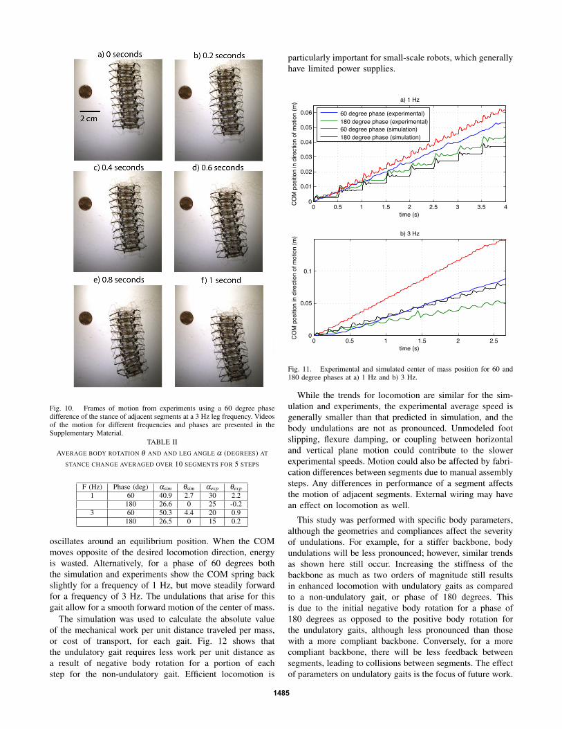
Fig. 10. Frames of motion from experiments using a 60 degree phasedifference of the stance of adjacent segments at a 3 Hz leg frequency. Videosof the motion for different frequencies and phases are presented in theSupplementary Material.
TABLE IIAVERAGE BODY ROTATION θ AND AND LEG ANGLE α (DEGREES) AT
STANCE CHANGE AVERAGED OVER 10 SEGMENTS FOR 5 STEPS
F (Hz) Phase (deg) αsim θsim αexp θexp1 60 40.9 2.7 30 2.2
180 26.6 0 25 -0.23 60 50.3 4.4 20 0.9
180 26.5 0 15 0.2
oscillates around an equilibrium position. When the COMmoves opposite of the desired locomotion direction, energyis wasted. Alternatively, for a phase of 60 degrees boththe simulation and experiments show the COM spring backslightly for a frequency of 1 Hz, but move steadily forwardfor a frequency of 3 Hz. The undulations that arise for thisgait allow for a smooth forward motion of the center of mass.
The simulation was used to calculate the absolute valueof the mechanical work per unit distance traveled per mass,or cost of transport, for each gait. Fig. 12 shows thatthe undulatory gait requires less work per unit distance asa result of negative body rotation for a portion of eachstep for the non-undulatory gait. Efficient locomotion is
particularly important for small-scale robots, which generallyhave limited power supplies.
0 0.5 1 1.5 2 2.5 3 3.5 40
0.01
0.02
0.03
0.04
0.05
0.06
time (s)
COM
pos
ition
in d
irect
ion
of m
otio
n (m
) a) 1 Hz
60 degree phase (experimental)180 degree phase (experimental)60 degree phase (simulation)180 degree phase (simulation)
0 0.5 1 1.5 2 2.50
0.05
0.1
time (s)
COM
pos
ition
in d
irect
ion
of m
otio
n (m
) b) 3 Hz
Fig. 11. Experimental and simulated center of mass position for 60 and180 degree phases at a) 1 Hz and b) 3 Hz.
While the trends for locomotion are similar for the sim-ulation and experiments, the experimental average speed isgenerally smaller than that predicted in simulation, and thebody undulations are not as pronounced. Unmodeled footslipping, flexure damping, or coupling between horizontaland vertical plane motion could contribute to the slowerexperimental speeds. Motion could also be affected by fabri-cation differences between segments due to manual assemblysteps. Any differences in performance of a segment affectsthe motion of adjacent segments. External wiring may havean effect on locomotion as well.
This study was performed with specific body parameters,although the geometries and compliances affect the severityof undulations. For example, for a stiffer backbone, bodyundulations will be less pronounced; however, similar trendsas shown here still occur. Increasing the stiffness of thebackbone as much as two orders of magnitude still resultsin enhanced locomotion with undulatory gaits as comparedto a non-undulatory gait, or phase of 180 degrees. Thisis due to the initial negative body rotation for a phase of180 degrees as opposed to the positive body rotation forthe undulatory gaits, although less pronounced than thosewith a more compliant backbone. Conversely, for a morecompliant backbone, there will be less feedback betweensegments, leading to collisions between segments. The effectof parameters on undulatory gaits is the focus of future work.
1485

1 2 3 4 5 6 7 8 9 1010
15
20
25
30
35
40
frequency (Hz)
cost
of t
rans
port
(mJ/
g/m
)
60 degree phase (undulatory gait)180 degree phase (non−undulatory gait)
Fig. 12. Cost of transport for phases of 60 degrees and 180 degrees fromsimulation.
V. CONCLUSIONS AND FUTURE WORK
The work presented here demonstrates locomotion en-hancement using undulatory gaits in a centipede millirobot.Increased leg and body angles for an undulatory gait, whicharise due to the passive dynamics of the system, were shownto increase the average speed of the millirobot compared to anon-undulatory gait. This suggests millirobots inspired by thebody morphology of centipedes can see improved straight-line locomotion by using undulatory gaits that feature groupsof legs pointing towards similar pivot points distributed alongthe length of the body. Similar gaits have been found innature [6], [5].
While the results shown here demonstrate that undulatorygaits in a centipede-inspired millirobot can enhance straight-line locomotion, the effect of physical parameters, such asgeometry, stiffnesses, actuator characteristics and number oflegs, were not studied extensively. Future work will focus onexamining the effect of parameters on undulatory patternsand locomotion performance.
This millirobot offers the potential to study many differentcharacteristics of legged robots at this scale. The modular de-sign will enable a comparison between robots with differentnumbers of legs. Studies will determine if there is an optimalnumber of legs for a centipede-inspired millirobot in termsof robustness, speed, efficiency, and stability.
Passive body flexibility in the horizontal plane was used tocreate undulations during straight-line locomotion, but futurework will focus on using this flexibility to perform dynamicturns. Additionally, a benefit of body flexibility in actualcentipedes is the ability to morph to surfaces and easilytransition between horizontal and vertical surfaces. Degreesof freedom will be added to the backbone to allow bodyflexibility in the vertical plane.
Robotic platforms such as the one presented here may beused to answer questions pertaining to how differing bodymorphologies affect walking at small scales. Using these sys-tems, it is possible to understand how the passive dynamics
resulting from different body types, whether myriapods orhexapods with flexible or rigid bodies, alter the effectivenessof different gaits. The insights gained can improve the designof walking robots at this scale.
VI. ACKNOWLEDGMENTS
This work was partially supported by the Wyss Institutefor Biologically Inspired Engineering (Harvard University)and the National Science Foundation (under award numberIIS-0811571). Any opinions, findings and conclusions orrecommendations expressed in this material are those of theauthors and do not necessarily reflect those of the NationalScience Foundation. This research was also made withGovernment support under and awarded by DoD, Air ForceOffice of Scientific Research, National Defense Science andEngineering Graduate (NDSEG) Fellowship, 32 CFR 168a.
REFERENCES
[1] A. Hoover, S. Burden, X. Fu, S. Sastry, and R. Fearing, “Bio-inspired design and dynamic maneuverability of a minimally actuatedsix-legged robot,” in IEEE International Conference on BiomedicalRobotics and Biomechatronics, 2010.
[2] A. Baisch, P. Sreetharan, and R. Wood, “Biologically inspired locomo-tion of an insect scale hexapod robot,” Proc. IEEE/RSJ InternationalConference on Intelligent Robots and Systems, 2010.
[3] P. Birkmeyer, K. Peterson, and R. Fearing, “DASH: A Dynamic16g Hexapedal Robot,” Proc. IEEE/RSJ International Conference onIntelligent Robots and Systems, 2009.
[4] R. Full and M. Tu, “Mechanics of a rapid running insect: two-, four-and six-legged locomotion,” Journal of Experimental Biology, vol.156, pp. 215–231, 1991.
[5] S. Manton and M. Harding, “The evolution of Arthropodan locomotorymechanisms - Part 3. The locomotion of the Chilopoda and Pau-ropoda,” Journal of the Linnean Society of London, Zoology, vol. 42,no. 284, pp. 118–167, 1952.
[6] B. Anderson, J. Shultz, and B. Jayne, “Axial kinematics and muscleactivity during terrestrial locomotion of the centipede Scolopendraheros,” Journal of Experimental Biology, vol. 198, no. 5, pp. 1185–1195, 1995.
[7] B. Jimenez and A. Ikspeert, “Centipede robot locomotion,” Master’sthesis, Ecole Polytechnique Federale de Lausanne, 2007.
[8] M. Sfakiotakis and D. Tsakiris, “Undulatory and pedundulatory roboticlocomotion via direct and retrograde body waves,” IEEE InternationalConference on Robotics and Automation, pp. 3457–3463, 2009.
[9] R. Wood, E. Steltz, and R. Fearing, “Optimal energy density piezo-electric bending actuators,” Sensors & Actuators: A. Physical, vol.119, no. 2, pp. 476–488, 2005.
[10] R. Wood, S. Avadhanula, R. Sahai, E. Steltz, and R. Fearing, “Micro-robot design using fiber reinforced composites,” Journal of MechanicalDesign, vol. 130, no. 5, p. 052304, 2008.
[11] K. Hoffman and R. Wood, “Towards a multi-segment ambulatorymicrorobot,” Proc. IEEE International Conference on Robotics andAutomation, 2010.
[12] M. Karpelson, G.-Y. Wei, and R. Wood, “Milligram-scale high-voltagepower electronics for piezoelectric microrobots,” IEEE InternationalConference on Robotics and Automation, 2009.
[13] R. Wood, E. Steltz, and R. Fearing, “Nonlinear performance limitsfor high energy density piezoelectric bending actuators,” IEEE In-ternational Conference on Robotics and Automation, pp. 3633–3640,2005.
[14] E. Steltz, M. Seeman, S. Avadhanula, and R. Fearing, “Power elec-tronics design choice for piezoelectric microrobots,” in IEEE/RSJInternational Conference on Intelligent Robots and Systems, 2006, pp.1322–1328.
[15] V. Chen and R. Tedrake, “Passive dynamic walking with knees: a pointfoot model,” Ph.D. dissertation, Massachusetts Institute of Technology,2007.
1486