Paso Link Mx
80
ROI-S05594-053E 080220 P ASOLINK N ETWORK M ANAGEMENT T ERMINAL NEC Corporation Copyright © 2008 PNMT (Java version) Operation Manual (for PASOLINK Mx)
Transcript of Paso Link Mx

ROI-S05594-053E 080220
P ASOLINK
N ETWORK
M ANAGEMENT
T ERMINAL
NEC Corporation Copyright © 2008
PNMT (Java version) Operation Manual
(for PASOLINK Mx)
ROI-S05594
- i -
Table of Contents
DOCUMENT WARRANTY ................................................................................................................ 1
1 GETTING STARTED ................................................................................................................... 2
1.1 INTRODUCTION................................................................................................................................. 2 1.2 CONVENTIONS USED IN THIS MANUAL ............................................................................................ 2 1.3 PNMT COMMUNICATION INTERFACES............................................................................................. 3
1.3.1 Communications....................................................................................................................... 3 1.4 EQUIPMENT CONFIGURATION OF PASOLINK MX........................................................................... 5
2 SYSTEM OPERATION & MAINTENANCE ............................................................................ 6
2.1 THE PNMT SCREEN ......................................................................................................................... 6 2.2 LAUNCHING THE PNMT APPLICATION............................................................................................. 8 2.3 LOGIN ............................................................................................................................................... 9
2.3.1 User Access Privilege Levels ................................................................................................. 10 2.4 SHUTTING DOWN PNMT................................................................................................................ 11 2.5 SEARCHING FOR AND CONNECTING TO SELECTED NETWORK ELEMENTS...................................... 12 2.6 CHANGE PASSWORD....................................................................................................................... 13 2.7 ALARM BUZZER SETTING............................................................................................................... 14 2.8 REFRESH......................................................................................................................................... 15 2.9 REMOTE VIEWING PNMT MAIN WINDOW ...................................................................................... 16 2.10 LICENSE ...................................................................................................................................... 17 2.11 MODULE DETECTED SYMBOL..................................................................................................... 18 2.12 OVERALL TAB ............................................................................................................................ 19 2.13 ODU TAB ................................................................................................................................... 20
2.13.1 ODU Tab ................................................................................................................................ 20 2.14 IDU TAB..................................................................................................................................... 22
2.14.1 IDU Tab.................................................................................................................................. 22 2.15 AUXILIARY I/O TAB ................................................................................................................... 26
2.15.1 Monitored Items ..................................................................................................................... 26 2.15.2 Photocoupler Input Setting ..................................................................................................... 26 2.15.3 Relay Output Setting .............................................................................................................. 27 2.15.4 Relay Configuration ............................................................................................................... 27
2.16 CONTROL (CTRL) TAB............................................................................................................... 31 2.16.1 Control Module ...................................................................................................................... 31 2.16.2 Setting the Date/Time............................................................................................................. 31 2.16.3 CPU Reset .............................................................................................................................. 32 2.16.4 Downloading the Configuration Files to the Control Module................................................ 33 2.16.5 Downloading a new Program File to the Control Module...................................................... 34 2.16.6 Downloading the Equipment Configuration Files to the Control Module ............................. 36 2.16.7 Uploading Configuration File to PNMT PC........................................................................... 37 2.16.8 Uploading Equipment Configuration File to PNMT PC ........................................................ 38
2.17 MAINTENANCE ........................................................................................................................... 39 2.17.1 Maintenance Menu ................................................................................................................. 40 2.17.2 Selecting Maintenance Mode ................................................................................................. 41
ROI-S05594
- ii -
2.17.3 TX Switch (for 1+1 Hot Stand-by system only)..................................................................... 42 2.17.4 RX Switch (for 1+1 system only)........................................................................................... 42 2.17.5 2 Port LAN Reset ................................................................................................................... 43 2.17.6 TX/RX Frequency .................................................................................................................. 43 2.17.7 Sub Band ................................................................................................................................ 43 2.17.8 TX Mute status ....................................................................................................................... 43 2.17.9 Loopback-1............................................................................................................................. 44 2.17.10 Loopback-2............................................................................................................................. 44 2.17.11 IF Loopback ........................................................................................................................... 45 2.17.12 CW (MOD Carrier) status ...................................................................................................... 45 2.17.13 ATPC Manual......................................................................................................................... 46 2.17.14 Shift Frequency ...................................................................................................................... 46 2.17.15 Antenna Alignment Mode (only available for the specific type of ODU) ............................. 46
2.18 EQUIPMENT SETUP...................................................................................................................... 47 2.18.1 Equipment Configuration window ......................................................................................... 47 2.18.2 Setup....................................................................................................................................... 49 2.18.3 Frequency Channel................................................................................................................. 51 2.18.4 Editing the NE Name.............................................................................................................. 51 2.18.5 Editing the Note for NE.......................................................................................................... 51
2.19 PROVISIONING ............................................................................................................................ 52 2.19.1 Provisioning window.............................................................................................................. 52 2.19.2 Manual Transmit Power Control (MTPC) Status................................................................... 55 2.19.3 Automatic Transmit Power Control (ATPC) Status ............................................................... 56 2.19.4 BER Alarm Threshold............................................................................................................ 58 2.19.5 Cluster ALM Setting (Input) .................................................................................................. 59 2.19.6 AIS Activation........................................................................................................................ 59 2.19.7 SW Priority............................................................................................................................. 59 2.19.8 Main Interface Setting ............................................................................................................ 60 2.19.9 SC Assignment ....................................................................................................................... 61 2.19.10 LAN INTFC-S........................................................................................................................ 62
2.20 LINK PERFORMANCE MONITOR .................................................................................................. 63 2.20.1 Viewing Summary Link Performance Monitor ...................................................................... 63 2.20.2 Threshold Setting.................................................................................................................... 64 2.20.3 Link Performance Monitor (1day / 15 min. Data) window .................................................... 65
2.21 REMOTE NETWORK MONITORING (RMON)............................................................................... 66 2.21.1 Viewing RMON LAN INTFC-S [Current] ............................................................................ 67 2.21.2 Viewing RMON LAN INTFC-S [15-min] ............................................................................. 68 2.21.3 Viewing RMON LAN INTFC-S [Daily]................................................................................ 70
2.22 NE STORED LOG......................................................................................................................... 72 2.22.1 NE Stored Log monitor .......................................................................................................... 72
2.23 VERSION TAB.............................................................................................................................. 73 2.23.1 Version Monitor ..................................................................................................................... 73
2.24 LICENSE IMPORT ......................................................................................................................... 74 2.24.1 License import ........................................................................................................................ 74

ROI-S05594
- 1 -
Document Warranty
1. The information contained in this document is subject to change without prior notice.
2. The PNMS/PNMT screenshots in this manual are only examples. Screens will vary according to equipment configurations, operation modes, setting parameters, PNMS/PNMT application program version, etc. Screens contained in this manual are current at the moment of publication, and may differ slightly from the actual screens on your PNMS/PNMT.
3. To use this manual, that you need a sound understanding of the restrictions, limitations and precautions involved in operating the equipment properly. Always refer to the respective manual to ensure proper operation of the equipment.

ROI-S05594
- 2 -
1 Getting Started
1.1 Introduction The PASOLINK Network Management Terminal (PNMT) was developed by NEC to manage its PASOLINK fixed point-to-point wireless access system networks. The PNMT is a scaled down version of the PASOLINK Network Management System (PNMS) that is designed as a maintenance tool for field engineers to locally and remotely monitor alarms, control points, generate reports, and archive data, all within a familiar graphical user interface, and all in real time. The PNMT is a mobile laptop computer fitted with the NEC PNMT software package that interfaces and controls NEC PASOLINK series short haul wireless communications equipment.
This software package remotely monitors and controls the status and configuration of an entire PASOLINK network with associated equipment including performance of the actual microwave links.
1.2 Conventions Used in This Manual
Font What the Font Represents Example
Italics For manual titles or related document names.
Please refer to PASOLINK Operation Manual for details.
Hostname Bold (or bold italics)
Items (phrases) in the user interface. Items (phrases) in the computer display. File and directory names.
The Overall window … XXXXXXXXX
[Button] Buttons on the user interface. Click on [OK] button to continue Click on [Execute] button to send command.
Menu Items A menu name followed by a colon (:) means that you must select the menu and then item. When the menu item is followed by an arrow ( ), a cascading menu is displayed .
Select System Login/Logout
<username>
A command variable for which the user must enter the appropriate value. This is also commonly used when asking for a password.
<password>
Keycap Keyboard keys. Press Enter key.

ROI-S05594
- 3 -
1.3 PNMT Communication Interfaces 1.3.1 Communications
Communications between the PNMT and the wireless communications network equipment can be
• via the PNMT port of the equipment,
• via the DSC to a remote node in the network.
1.3.1.1 PNMT Port Interface
The PNMT port is located on the front of the equipment.
PNMT Cable
IDU PNMT port
PNMT
ODU
PASOLINK Mx IDU
1+0 (4x2M), 1+0 (20x2M)
PNMT Cable
IDU PNMT port
PNMT
ODU
PASOLINK Mx IDU
1+0, 1+0 (Expandable), 1+1 (Hot Stand-by), 1+1 (Twin Path)

ROI-S05594
- 4 -
The PNMT port consists of an RJ-45 connector that plugs into Control (CTRL) Module installed in the IDU via a serial cable which connects to the relevant communications port of the PNMT Computer.
The PNMT port has the following properties:
• Port Configuration: RS-232
• Connector type: RJ-45 modular jack
• Bit per second rate: 1200/2400/4800/9600/19200 (default 19200)
• Stop bits: 1
• Data bit length: 8
• Parity: None.
The following table shows the pin allocation for the connection between the IDU PNMT port and the PNMT PC.
PNMT (PC) to PASOLINK Mx (PNMT port)
D-sub 9-pin (F) RJ45
123456789
12345678
DCDRXDTXDDTRGNDDSRRTSCTSRI
RS-232C123456789
CDTXDRXDDSRGNDDTRCTSRTS
RS-232C12345678
3 m
PASOLINK MxPNMT port
PC (PNMT)
Cabling Diagram for PNMT PC to PNMT Port connections
PNMT (PC) to PNMT port (PASOLINK Mx)

ROI-S05594
- 5 -
1.4 Equipment Configuration of PASOLINK Mx PASOLINK Mx has 6 types of IDU.
• 1+0 (4x2M)
• 1+0 (20x2M)
• 1+0
• 1+0 (Expandable)
• 1+1 (Hot Stand-by)
• 1+1 (Twin Path)
Every IDU has 2 optional slots.
1+0 (4x2M) and 1+0 (20x2M) can support TNS Card / PNMS Card in Slot1, and LAN INTFC-S in Slot2. 1+0, 1+0 (Expandable), 1+1 (Hot Stand-By) and 1+1 (Twin Path) support 2M INTFC-M (32x2M) in Slot1, and 2M INTFC-S (8x2M) / LAN INTFC-S in Slot2.
Slot 2Slot 1
1+0 (4x2M), 1+0 (20x2M)
Slot 2Slot 1
1+0, 1+0 (Expandable), 1+1 (Hot Stand-by), 1+1 (Twin Path)

ROI-S05594
- 6 -
2 System Operation & Maintenance
This chapter explains the menu structure and procedures for operating of the PNMT. The explanation uses typical PNMT screenshots to illustrate the menu hierarchy.
2.1 The PNMT Screen
The PNMT window is composed of the following main areas (Refer to Figure 1).
Title bar The title bar of a window is used to indicate the title of the window. Standard Menu bar The common menu bar of the window presents the System and Help options, illustrates which commands can be executed from among the various options. The Help function can also display a PDF version of this operation manual. NE-specific Menu bar This menu is a list of functions involving the network element (NE) displayed in the PNMT. Configuration, Event Log, and Link Performance Monitor functions can be executed with the NE-specific Menu bar. Block Diagram The block diagram shows the equipment comprising the PASOLINK Mx wireless communication system. Its main purpose is to show the current alarm status summary for the equipment in the display window. You can click on a specific block to display the status of the network elements (NE) in the data window. Data window This window displays in detail the status and alarm items of a specific NE. You can select the tab or the block of a specific NE which you wish to monitor in the data window. Tabs To view the status and alarms in the specific part of the NE, click on the tab at the bottom of the Data window. User Login This indicates the user who is currently logged-in to the PNMT. One Touch Expandable Button / Divider Initially the PNMT screen is split evenly to display the data from the two NE’s withing a hop by using a divider. Click this button to move the divider to the edge of the window.

ROI-S05594
- 7 -
Figure 1 Standard Components of PNMT Window
Standard Tool Bar
Tabs
Block Diagram NE-Specific Menu Bar
Data Window
User login
Standard Menu Bar
Title Bar
Selectable Field Command Button
One Touch Expandable Button
Divider

ROI-S05594
- 8 -
2.2 Launching the PNMT Application To start PNMT:
1. Turn system power ON the system.
NOTE
Connect the PNMT cable 30seconds after IDU power has been turned ON and make sure that the PNMT cable is connected between Com 1 port of the PNMT PC and the PNMT port of the IDU.
2. Login to Windows.
3. Click Start Programs PNMTj Pnmt, then continue to the login window.
NOTE
Please do not change the clock settings of your computer once PNMT has started.

ROI-S05594
- 9 -
2.3 Login Users are registered by means of login name and password.
To protect the network and the network management system from unauthorized access or modifications, five levels of users with different access privileges are defined (refer to the table shown in section 2.3.1 User Access Privilege Levels). The functions available in the window depend on the individual user’s access level. .
The highest or administrator level has full access to the network and the management system.
To login:
1. Start PNMT, and then Login window appears.
Login window
2. Enter the <User name>.
3. Enter the valid <Password> for the specific user.
4. Click [Login].
If you wish to exit the program, click [Exit].

ROI-S05594
- 10 -
2.3.1 User Access Privilege Levels
ITEM Monitor User Local Remote AdminSYSTEM ALARM BUZZER -
CONNECT(Remote Login) - - -MODULE DETECTED
(Show Module Detected Symbol)MODULE DETECTED
(Open Control-Equipment Setup)- -
IDU COMMON/MAIN DETAILAUX I/O INPUT -
OUTPUT -RELAY CONFIGURATION -
CTRL CONTROL DATE/TIME - -CPU RESET - -
DOWNLOAD CONFIGURATION FILE - - - -PROGRAM FILE - - - -EQUIPMENT CONFIG. FILE - - - -
UPLOAD CONFIGURATION FILE - - - -EQUIPMENT CONFI.G. FILE - - - -
EQUIPMENT EQUIPMENT SETUP SETUP - -SETUP CTRL NE NAME - -
NOTE -PROVISIONING MTPC STATUS MTPC TX POWER - -
RX THRESHOLD - -ADDITIONAL ATT - -
ATPC STATUS ATPC (MAX) - -ATPC (MIN) - -RX THRESHOLD - -ADDITIONAL ATT - -ODU ALM MODE - -
BER ALM HIGH BER - -THRESHOLD LOW BER - -CLUSTER ALM CLUSTER ALM 1 - -SETTING(INPUT) CLUSTER ALM 2 - -SW PRIORITY TX SW PRIORITY - -
RX SW PRIORITY - -CHANNEL USAGE ERROR REPORT - -AIS RECEIVED REPORT - -AIS GENERATED REPORT - -AIS RECEIVED CONDITION SETTING - -CHANNEL USAGE - -
AIS ACTIVARTION AIS ACTIVATION CONDITION - -SC ASSIGNMENT SETTING - -LAN INTFC-S PORT SETTING - -LAN INTFC-M PORT SETTING - -
MAINTENANCE MAINT -TX SWITCH - -RX SWITCH - -2 PORT LAN RESET - -TX/RX FREQUENCY - -SUB BAND - -TX MUTE - -IF LOOPBACK - -CW - -ATPC MANUAL - -SHIFT FREQUENCY - -ANTENNA ALIGNMENT MODE - -
2M CH 2M CH LOOPBACK - -LOOPBACK-1/2 2M CH LOOPBACK-1 ALL CH RESET - -
2M CH LOOPBACK-2 ALL CH RESET - -
User Name and Accessible Functions
SUMMARY
MAIN INTFCSETTING
: Available, –: Not AvailableFunctions
Category

ROI-S05594
- 11 -
ITEM Monitor User Local Remote AdminEVENT LOG SAVE TO DISK -PMON PMON PMON THRESHOLD -
SAVE TO DISK -RMON RMON 15-MIN SAVE TO DISK -
RMON DAILY SAVE TO DISK -
*Admin: Enable to access to the all Network Elements.*Remote: Enable to access to the all Network Elements.
(Disable to change network configuration and change program with downloading)*Local: Enable to access to Local NE and Opposite NE.
(Disable to change network configuration and change program with downloading)*User: Enable to access to items which doesn't effect to the equipment.*Monotor: Enable to monitor only and disabled to control.
User Name and Accessible Functions: Available, –: Not Available
FunctionsCategory
2.4 Shutting Down PNMT
To close the PNMT application:
1. Click System -> Exit on the Menu bar on the main window
2. Click [OK] to confirm closing the application.

ROI-S05594
- 12 -
2.5 Searching for and Connecting to Selected Network Elements The summary description of the current network element (Network Element Name, Equipment Type, Opposite Network Element, etc.) where PNMT is connected is displayed with this function. Summary description of the opposite network element belonging to that link is also displayed.
To search for or connect to, a particular Network Element:
1. Click System Connect… on menu bar of PNMT main window.
NOTE
Initially only the current NE physically connected to the PNMT and its opposite NE counterpart will be shown in the Network Element List.
2. Click icon in the tool bar or List Search for Network Element in the menu bar on the Network Element List window to display all connectable Network Elements in the network.
3. Select and highlight the network element to be viewed.
4. Click icon in the tool bar or List Connect to Network Element in the menu bar on the network element List window. The PNMT main window of the selected network element and its opposite NE counterpart will be displayed.

ROI-S05594
- 13 -
2.6 Change Password To change the password:
1. Click System Change Password on the menu bar on main window.
2. Enter the Old password.
3. Enter New Password
4. Enter new password in the Confirm New Password field to confirm.
5. Click [OK].
NOTE
For details on initial user name and password, please refer to PNMT Installation manual.

ROI-S05594
- 14 -
2.7 Alarm Buzzer Setting This function is used to activate and set the Alarm Buzzer. The desired sound scheme can also be set using this function.
To set the Alarm Buzzer:
1. Click System Alarm Buzzer in the main window.
2. Select the Wave file box to activate the buzzer. No sound is the initial factory setting of the PNMT.
3. Enter the location of the sound file (*.wav) Otherwise; click […] to locate the desired file. You can also preview the *.wav file by clicking on the arrow next to the browse button.
4. Click [OK] to activate the new setting.
NOTE
When the text column is blank, it is possible to set it. In this case, the buzzer sound does not ring even though the buzzer stop function is enabled.

ROI-S05594
- 15 -
2.8 Refresh This function is available only for PNMT. This function enables PNMT to acquire all status data manually and NE information to be updated.
To Refresh:
1. Click Refresh Refresh in the main window or click on the refresh icon in the tool bar.
NOTE
Metered items such as TX power, RX level, power supply and BER are automatically refreshed every 15 seconds. This function is used when the immediate refresh of these metered items is necessary or when immediate confirmation of all current status information is required.

ROI-S05594
- 16 -
2.9 Remote Viewing PNMT main window You can view a target link within one Root-NE cluster of the Pasolink+ network by searching through the connected NE’s and then connecting to a target NE. Please refer to Section 2.5 Searching for and Connecting to Selected Network Elements. This function allows remote connection to any NE in the network.
NOTE: For multi-Root-NE network, you can only connect to NE’s that belong to the same network as Root-NE as the local NE to which you are directly connected – via the PNMT cable.
PNMT Main window (1+0 configuration)

ROI-S05594
- 17 -
2.10 License To protect PNMT functions, the PNMT application includes license files.
To display the current license status,
1. Click Help License… in the main window.
When changing the license file, click [Import].

ROI-S05594
- 18 -
2.11 Module Detected Symbol If IDU detects the difference between the module configuration and currently inserted modules in the slot(s), module detected symbol ( ! ) will be flashed in the block-diagram portion of the PNMT screen. You can click on this symbol to be redirected to the Equipment Setup window or go to Configuration Equipment Setup Slot/LAN tab to synchronize the module configuration.
1. Click [<-] symbol to apply the detected (inserted) module in the configuration.
(See 2.18 Equipment Setup)
Module Detected Symbol

ROI-S05594
- 19 -
2.12 Overall Tab This tab is displayed at startup. The Overall tab provides an overall snapshot of the most significant monitored items in the NE.
The Overall tab gives a snapshot of the important settings of the NE. This window only displays current settings and there is no control function associated with this window.
The following items are displayed with this tab:
• TX Frequency – the currently used transmission frequency.
• RX Frequency – the currently used reception frequency
• MTPC TX Power – the current value (in dB) of the Manual Transmitter Power Control attenuation set in the ODU. The MTPC Attenuation will only have a valid data if the MTPC is enabled.
• Frame ID – the current predefined value of the frame ID of the NE.
• TX Power Control – shows the current power control mode used by the ODU. The TX Power Control is either Automatic Transmitter Power Control (ATPC) or Manual Transmitter Power Control (MTPC).
• Slot1 – the current setting of Slot1.
• Slot2 – the current setting of Slot2.
• Transmission Capacity – shows the transmission capacity of the system.
• Modulation – the current modulation type used.
• Selected TX (for hot standby configuration only) – shows the currently used signal transmission.
• Selected RX (for 1+1 system only) – shows the currently used signal reception system.
Overall Tab (1+0 configuration)
Overall Tab (1+1 configuration)

ROI-S05594
- 20 -
2.13 ODU Tab This function is used to display the values and status of the monitored items of the ODU. This window only displays current settings and there are no control functions associated with this window.
To set the ODU parameters see the chapters on Equipment Setup and Provisioning.
2.13.1 ODU Tab
To view the alarm and status display of the ODU:
1. Click ODU tab in PNMT main window of the target NE.
ODU Tab (1+1 Configuration)
ODU Tab (1+0 Configuration)

ROI-S05594
- 21 -
Monitored Items in the ODU
TX PORTION Alarm o TX INPUT: alarm occurs when the TX IF input signal from the IDU is lost. Item/Status area is
shown with transparency letters and gray background in case PS Alarm, ODU CPU Alarm or IF Cable Short Alarm.
o TX POWER: TX RF Power decreases 3 to 6 dB from nominal value. Item/Status area is shown with transparency letters and gray background in case PS Alarm, ODU CPU Alarm or IF Cable Short Alarm.
o Selected/Not Selected: shows the current system used for signal transmission. (for 1+1 systems only)
Metering TX Power: The transmitted power of the ODU in dBm. Item and status area are shown and item area filled with black font, status is no information in case PS Alarm, ODU CPU Alarm or IF Cable Short Alarm.
RX PORTION Alarm o RX LEVEL: alarm occurs when the input level decreases by preset value from squelch level.
Item/Status area is shown with transparency letters and gray background in case PS Alarm, ODU CPU Alarm or IF Cable Short Alarm.
o Selected/Not Selected: shows the current system used for signal reception. (for 1+1 systems only)
Metering RX Level: The received level interpreted in dBm. Item and status area are shown and item area filled with black font, status is no information in case PS Alarm, ODU CPU Alarm or IF Cable Short Alarm. COMMON PORTION Alarm o APC: this alarm occurs when the Local Oscillator is locked out. Item/Status area is shown with
transparency letters and gray background in case PS Alarm, ODU CPU Alarm or IF Cable Short Alarm.
o ODU CPU: this alarm occurs when the communication between the ODU and the IDU is lost. Item/Status area is shown with transparency letters and gray background in case PS Alarm
Metering Power Supply: Display PS voltage value (V). Item/Status area is shown with transparency letters and gray background in case PS Alarm, ODU CPU Alarm or IF Cable Short Alarm.
ROI-S05594
- 22 -
2.14 IDU Tab This function is to display the values and status of the monitored items of the IDU. This window only displays current settings and there is no control functions associated with this window.
To set the IDU parameters see the chapters on Equipment Setup and Provisioning.
2.14.1 IDU Tab
To view the alarm and status of the IDU:
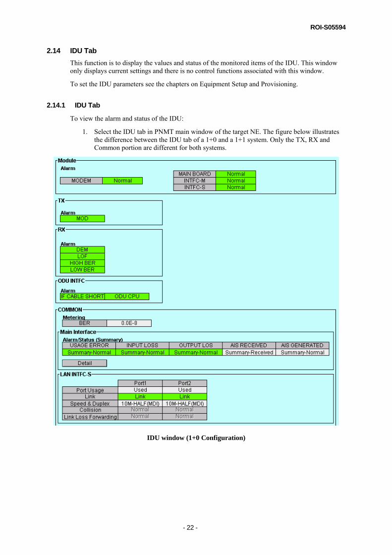
1. Select the IDU tab in PNMT main window of the target NE. The figure below illustrates the difference between the IDU tab of a 1+0 and a 1+1 system. Only the TX, RX and Common portion are different for both systems.
IDU window (1+0 Configuration)

ROI-S05594
- 23 -
IDU Window (1+1 Configuration)
Detail Window of Main Interface
ROI-S05594
- 24 -
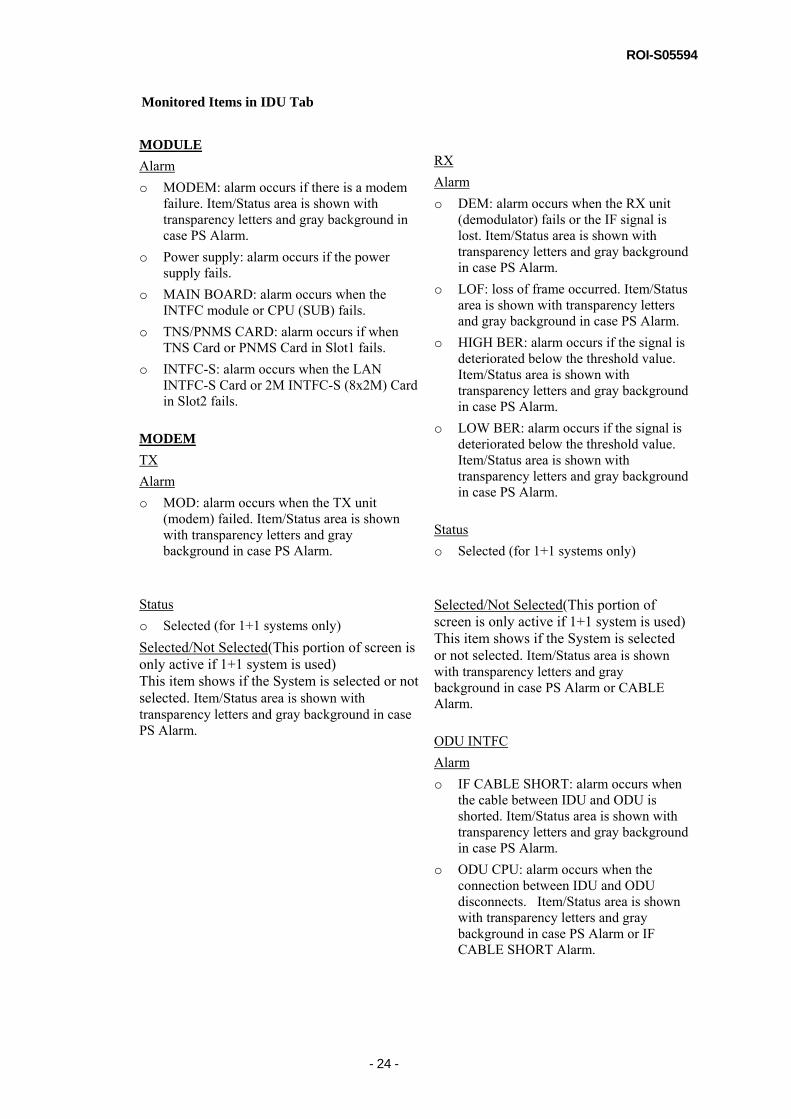
Monitored Items in IDU Tab
MODULE Alarm o MODEM: alarm occurs if there is a modem
failure. Item/Status area is shown with transparency letters and gray background in case PS Alarm.
o Power supply: alarm occurs if the power supply fails.
o MAIN BOARD: alarm occurs when the INTFC module or CPU (SUB) fails.
o TNS/PNMS CARD: alarm occurs if when TNS Card or PNMS Card in Slot1 fails.
o INTFC-S: alarm occurs when the LAN INTFC-S Card or 2M INTFC-S (8x2M) Card in Slot2 fails.
MODEM TX Alarm o MOD: alarm occurs when the TX unit
(modem) failed. Item/Status area is shown with transparency letters and gray background in case PS Alarm.
Status o Selected (for 1+1 systems only) Selected/Not Selected(This portion of screen is only active if 1+1 system is used) This item shows if the System is selected or not selected. Item/Status area is shown with transparency letters and gray background in case PS Alarm.
RX Alarm o DEM: alarm occurs when the RX unit
(demodulator) fails or the IF signal is lost. Item/Status area is shown with transparency letters and gray background in case PS Alarm.
o LOF: loss of frame occurred. Item/Status area is shown with transparency letters and gray background in case PS Alarm.
o HIGH BER: alarm occurs if the signal is deteriorated below the threshold value. Item/Status area is shown with transparency letters and gray background in case PS Alarm.
o LOW BER: alarm occurs if the signal is deteriorated below the threshold value. Item/Status area is shown with transparency letters and gray background in case PS Alarm.
Status o Selected (for 1+1 systems only) Selected/Not Selected(This portion of screen is only active if 1+1 system is used) This item shows if the System is selected or not selected. Item/Status area is shown with transparency letters and gray background in case PS Alarm or CABLE Alarm. ODU INTFC Alarm o IF CABLE SHORT: alarm occurs when
the cable between IDU and ODU is shorted. Item/Status area is shown with transparency letters and gray background in case PS Alarm.
o ODU CPU: alarm occurs when the connection between IDU and ODU disconnects. Item/Status area is shown with transparency letters and gray background in case PS Alarm or IF CABLE SHORT Alarm.

ROI-S05594
- 25 -
COMMON Metering BER: The current overall value of the Bit-Error-Rate MAIN INTFC Item/Status area is shown with transparency letters and gray background in case every channel is Not Used. Alarm/Status o USAGE ERROR: alarm occurs when 2MB
bipolar signal is inputted into the channel that has been chosen “Not Used”.
o INPUT LOSS: alarm occurs when 2MB bipolar signal is disconnected.
o OUTPUT LOSS: alarm occurs when the received signal from radio link is lost.
o AIS RECEIVED: indicates the status of AIS RECEIVED signal for transmitting channel in the MAIN INTFC. Status area is shown with transparency letters and gray background in case AIS Received Report is Not Reported.
o AIS GENERATED: indicates the status of AIS generation signal for receiving channel in the MAIN INTFC. Status area is shown with transparency letters and gray background in case AIS Generated Report is Not Reported.
LAN INTFC-S Item/Status area is shown with transparency letters and gray background in case 2 Port LAN Radio Mapping is Not Used. o Port Usage: enables to apply the each
port. o Link: alarm occurs when the link fails on
each port. Status area is shown with transparency letters and gray background in case Port Usage is Not Used.
o Speed & Duplex: indicates the status of Speed & Duplex. Status area is shown with transparency letters and gray background in case Port Usage is Not Used.
o Collision: indicates the status of Collision. Status area is shown with transparency letters and gray background in case Port Usage is Not Used, Collision Report is Not Reported or Speed & Duplex is Full.
o Link Loss Forwarding: indicates the status of Link Loss Forwarding. Status area is shown with transparency letters and gray background in case Port Usage is Not Used or Link Loss Forwarding is Disable.
ROI-S05594
- 26 -
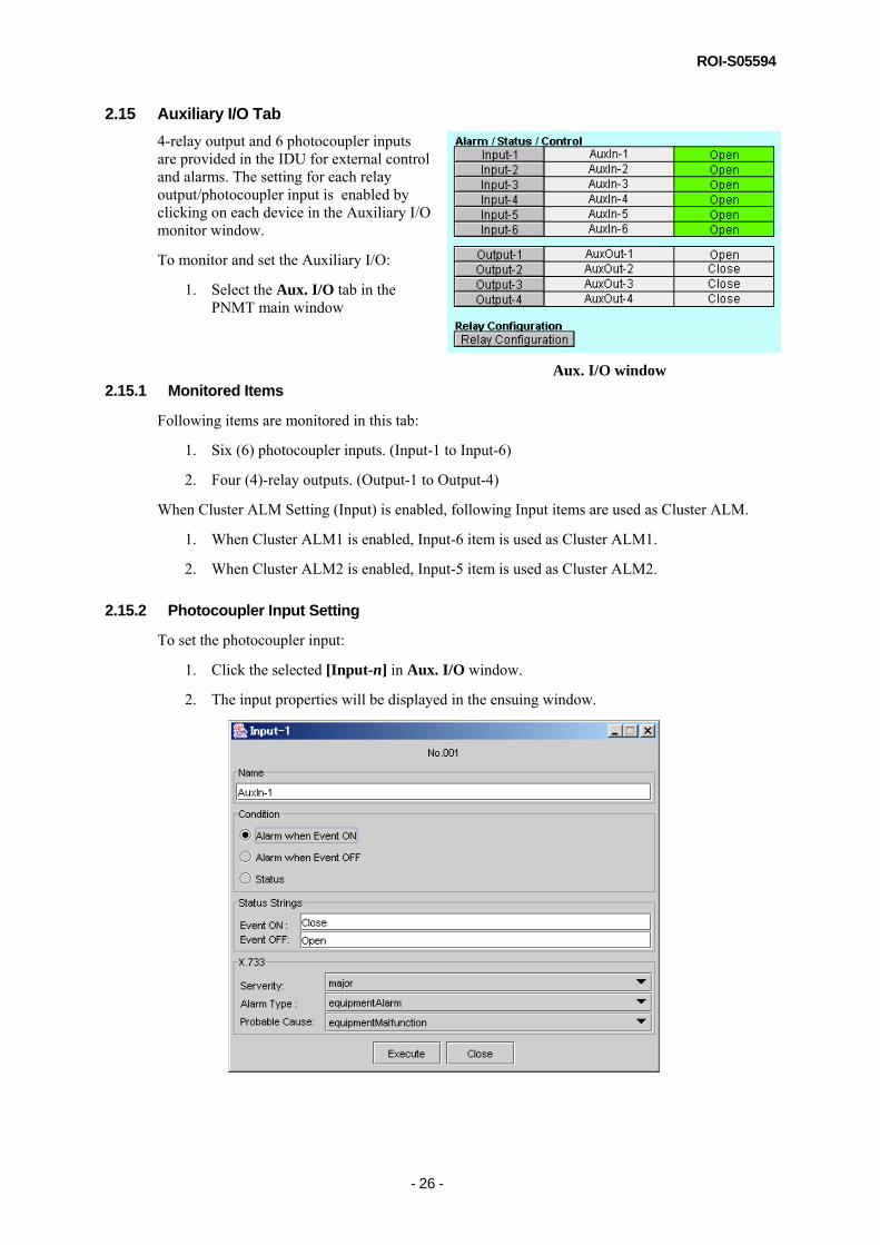
2.15 Auxiliary I/O Tab 4-relay output and 6 photocoupler inputs are provided in the IDU for external control and alarms. The setting for each relay output/photocoupler input is enabled by clicking on each device in the Auxiliary I/O monitor window.
To monitor and set the Auxiliary I/O:
1. Select the Aux. I/O tab in the PNMT main window
2.15.1 Monitored Items
Following items are monitored in this tab:
1. Six (6) photocoupler inputs. (Input-1 to Input-6)
2. Four (4)-relay outputs. (Output-1 to Output-4)
When Cluster ALM Setting (Input) is enabled, following Input items are used as Cluster ALM.
1. When Cluster ALM1 is enabled, Input-6 item is used as Cluster ALM1.
2. When Cluster ALM2 is enabled, Input-5 item is used as Cluster ALM2.
2.15.2 Photocoupler Input Setting
To set the photocoupler input:
1. Click the selected [Input-n] in Aux. I/O window.
2. The input properties will be displayed in the ensuing window.
Aux. I/O window

ROI-S05594
- 27 -
2.15.2.1 Setting the Selected Input to Alarm or Status 1. Select the Condition and X.733 setting of the selected input. You can select the input
status when the target input will send the alarm event to the PNMSj/PNMTj. Also you can preset the input to just send the status event instead of the alarm event. The alarm input severity is defined in the X.733 recommendations. Select the severity of the alarm, its type and probable cause by clicking on the pull-down arrow on the right-hand side of the field.
2. Enter the name and status strings of the selected input in the Name, Event ON and Event OFF field. A maximum of 32 characters can be used.
3. Click [Execute] to activate the selected state of the device.
4. Click [Close] when finished.
2.15.3 Relay Output Setting
To set the relay output:
1. Click [Output-n] in Aux. I/O window.
2. To define the open or close status of the selected relay output, click Event ON or Event OFF respectively.
3. Enter the desired strings for the open and close status of the relay output in the appropriate Event ON and Event OFF fields. A maximum of 32 characters can be used.
4. Click Name tab.
5. Enter the desired name of the relay output on the Name field. A maximum of 32 characters can be used.
6. Click [Execute] to carry out the command.
7. Click [Close] when finished.
2.15.4 Relay Configuration
There are 7 relays in the IDU. Consequently, 7 parallel alarms can be defined. Relays RL01, RL02 and RL03 have fixed alarms. Maintenance, PS ALM and CPU Alarm are outputted on RL01, RL02 and RL03 respectively.
RL04 to RL07 are user-definable relays for Housekeeping (HK), Cluster alarm or other external parallel alarms. If the HK-OUT’s are enabled, RL04 to RL07 are allocated for Housekeeping (HK). Cluster alarm 1 and 2 are outputted on RL07 and RL06 respectively.
NOTE
Relays RL04 to RL07 are available for allocation of Housekeeping (HK), Cluster alarms and equipment alarms. These alarms are outputted on the same relay.
CAUTION:
When setting RL07 or RL-06 to output the cluster alarm, it is recommended that Housekeeping (HK) and equipment alarms be removed from the form – this is to ensure that RL07 or RL06 will output only the cluster alarm.

ROI-S05594
- 28 -
The PNMT allows the user to configure the relays in a table format. The columns indicate the relays (RL01 to RL07) and the rows indicate the parallel alarms available. The following indicators are used in the table:
Out – indicates that the alarm - in the corresponding row, is issued on the corresponding relay.
HK – Indicates that the corresponding relay is used for House Keeping. Blank button – not related to the corresponding alarm.
To set the relay configuration:
1. Click [Relay Configuration] in Aux. I/O window.
2. Select the HK-OUT used in the equipment. There are four (4) available HK-OUT’s in the system. Selecting “1/2/3/4” button means all HK-OUT’s will be enable; “1/2/3” means only HK-OUT 1, 2 and 3 will be enabled; and so on. If the HK-OUT’s will not be used, select “Disable” button.
3. Click the button(s) that corresponds to the target alarm(s) and relay(s).
4. Click [Execute] to apply the new relay configuration.
5. Click [Close] when finished.

ROI-S05594
- 29 -
The following alarms are available for allocation on the relays.
Relay Configuration List (1+0)

ROI-S05594
- 30 -
Relay Configuration List (1+1)
NOTE
When maintenance mode is ON, all other alarms except HK and cluster alarms are masked.

ROI-S05594
- 31 -
2.16 Control (CTRL) Tab 2.16.1 Control Module
1. Select the CTRL tab in PNMT main window of the target NE.
The following items can be monitored and controlled in the CTRL window:
• Calendar Alarm • CPU (SUB) Alarm • Date/Time • CPU Reset • Download Configuration File • Download Program File • Download Equipment Configuration File • Upload Configuration File • Upload Equipment Configuration File
2.16.2 Setting the Date/Time
The Date and Time stored in the Control module can be displayed and adjusted using this function.
To set the Date/Time:
1. Click [Date/Time] in the CTRL window.
a. To check the Date and Time on the Control module: a-1. Select Get Date/Time in the Date/Time window. a-2. Click [Execute]. a-3. The current date and time in the control will be displayed in the Date and Time field. b. To set the Date and Time on the Control module: b-1. Select Set Date/Time in the Date/Time window. b-2 Enter the date at Date field in the MM/dd/yyyy format, where MM is for month, dd is
for date and yyyy is for year. b-3. Enter the time at the Time Field in the hh:mm format, where hh is for hour and mm is
for minutes. b-4. Click [Execute]. b-5. Click [Close] when finished.
NOTE
To set the values of the Date and Time fields to the same value as the PNMT computer, check the Display PC Time box

ROI-S05594
- 32 -
2.16.3 CPU Reset
The Control module can be reset using this function
*The CPU Reset window is not available when MAINT is OFF.
NOTE
Resetting the Control module will not affect the traffic. The connection to the selected NE will be lost a few minutes and will be automatically re-connected.
NOTE
MAINT, TX Mute, CW, Loopback, ATPC Manual and CH Loopback will be cleared and TX/RX Switch will be Auto if the power is turned off and on or the RESET switch is depressed.
To reset the Control module:
1. Click [CTRL Reset] in CTRL window.
2. You can select the “with ROM (Program) Switching” option if you want to switch to a newly downloaded Control module Program file.
3. Click [Execute] to continue the Control module reset operation.
NOTE
Switch ON maintenance mode first before executing CPU Reset.

ROI-S05594
- 33 -
2.16.4 Downloading the Configuration Files to the Control Module
This function is for download the network configuration files from the PNMT to the Control module. The network configuration file – pp_network.cfg, contains the IP addresses of the target NE as well opposite NE and the information about the network where the target NE is located. The pp_mib.cfg file contains the information about the equipment (i.e. name, pm type, etc.) and housekeeping (Aux. I/O).
To download the new configuration file to the CTRL:
1. Click [Configuration File] in the Download (PC>>CTRL) section on CTRL window.
2. Select the type of file to be downloaded in the Type list.
3. Enter the location of the configuration file in the File field, or click [Browse] to locate the file on the local hard disk or diskette.
WARNING!!!
Make sure that the correct configuration file is downloaded to the correct Control module. Incorrect configuration files can cause Control module or network failure.
4. Click [Execute] to start the operation.
*[Execute] Button is only available when MAINT is ON.
NOTE
Switch ON maintenance mode first then executing the Download Configuration File.
5. A message window indicating the status of the operation will appear. It will close
automatically once the operation is finished.
WARNING:
Make sure that you have successfully downloaded the configuration file before attempting an Update. Otherwise the Control module will switch to an empty ROM that may cause the Control module failure.
6. Click [Update] to activate the new configuration file(s).
*[Update] Button is only available when MAINT is ON. (“Switch to maintenance mode first” is displayed in case it is set to OFF.)

ROI-S05594
- 34 -
7. Select the appropriate box for the type of configuration file that will be updated. One or more configuration file(s) can be updated by checking the selection box of the configuration file name. Click on [Execute] button to start the operation. The "with ROM (CTRL Program) Switching" box is for switching to the ROM with the new CTRL Program and has the same function that was previously described in section 2.16.3 CPU Reset.
NOTE
When updating the pp_network.cfg file, NE-to-NE communication will be lost when the Control module re-initializes to the new system configuration. This WILL NOT affect the radio link. During this time PNMT connection to the NE will be disrupted but it will automatically be restored after the Control module resets.
NOTE
Updating the CTRL will not affect the traffic. The connection to the selected Pasolink will be disrupted for a few minutes but will be automatically re-stored.
8. Click [Close] when done.
2.16.5 Downloading a new Program File to the Control Module
This function is used to update the application program on the Control module. This operation affects only the NMS communication but not the wireless link, and will not disrupt communication.
To download the program file to Control module:
1. Click [Program File] in the Download (PC>>CTRL) section on CTRL window.

ROI-S05594
- 35 -
2. Select the module select button of CTRL. If you tick the “with Self Reset” the Control module will be reset automatically after program file download is completed. In this case, you won’t need to do steps 5 thru 8.
3. Enter the appropriate location of the program file (*.out) in the File field. Otherwise, click [Browse] to locate the file.
WARNING!!!
Make sure that the correct program file is downloaded to the Control module. Incorrect program file will lead to failure.
4. Click [Execute] to start the operation.
*[Execute] Button is only available when MAINT is ON.
NOTE
Switch ON maintenance mode first before executing Download Program File.
5. A message window will appear displaying the status of the operation. It will close
automatically once the download is completed.
NOTE
This operation may take several minutes depending on the program file size
6. Click [CPU Reset…] to switch to the new program file.
*[CPU Reset] Button is only available when MAINT is ON. (“Switch to Maintenance mode first” is displayed in case it is set to OFF.)
7. Check the with ROM (Program) Switching box.
8. Click [Execute] to complete the switch to the new program file.
NOTE
The connection to the selected NE will be disrupted a few minutes will automatically be restored.
9. Click [Close] when done.

ROI-S05594
- 36 -
2.16.6 Downloading the Equipment Configuration Files to the Control Module
This function is used to download equipment configuration files from the PNMT to the Control module. The equipment configuration file contains the radio configuration data (i.e. frequency, main interface) and provisioning data (i.e. BER alarm threshold).
To download new configuration file to the NE:
1. Click [Equipment Config. File] in the Download (PC>>CTRL) section on CTRL window.
2. Click [Browse] to locate the file on the local hard disk or diskette.
WARNING!!!
Make sure that the correct equipment configuration file is downloaded to the correct Control module. Incorrect configuration file will lead to Control module or network failure.
3. Click [Execute] to start the operation.
*[Execute] Button is only available when MAINT is ON. (“Switch to maintenance mode first” is displayed in case it is set to OFF.)
4. A message window indicating the status of the operation will appear. It will close automatically once the operation is finished.
WARNING!!!
Make sure that you have successfully downloaded the configuration file before doing Update. Otherwise the Control module will switch to an empty ROM that may cause Control module failure.

ROI-S05594
- 37 -
5. Click [Update…] to activate the new equipment configuration file. Click [Execute] to start the update operation.
*[Update] Button is only available when MAINT is ON.
NOTE
Switch ON maintenance mode first before executing Download Equipment Configuration File.
NOTE
The connection to the selected NE will be lost a few minutes and will automatically re-connect.
6. Click on [Close] button when done.
2.16.7 Uploading Configuration File to PNMT PC
This function is used to upload the configuration file from the Control module of the selected NE to the PNMT PC.
To upload the configuration file from the Control module to the PNMT:
1. Click [Configuration File] in the Upload (CTRL>>PC) section on the CTRL window.
2. Select the type of file to be uploaded with the Type field.
3. Enter the desired file name for the uploaded file. And select and the directory where the uploaded file will be saved.
4. Click [Execute] to start the operation.
5. A message window indicating the status of the operation will appear. It will close automatically once the operation is completed.
6. After the upload is finished, click [Close].
7. Verify that the file was uploaded on the specified directory.

ROI-S05594
- 38 -
2.16.8 Uploading Equipment Configuration File to PNMT PC
This function is used to upload the equipment configuration file from the Control module of the selected NE to the PNMT PC.
To upload the equipment configuration file from the Control module to the PNMT:
1. Click [Equipment Config. File] in the Upload (CTRL>>PC) section on the CTRL window.
2. Click [Execute] to start the operation.
3. Enter the desired file name for the uploaded file. And select the directory where the uploaded file will be saved.
4. A message window indicating the status of the operation will appear. It will close automatically once the operation is completed.
5. After the upload is finished, click [Close].
6. Verify that the file was uploaded on the specified directory.

ROI-S05594
- 39 -
2.17 Maintenance There are several maintenance control items that can be executed in the maintenance menu. The function of each control is as follows.
MAINT: To switch Maintenance mode to ON
TX Switch: To control the TX switch manually
(for 1+1 Hot Standby system only.)
RX Switch: To control the RX switch manually
(for 1+1 system only)
2Port LAN Reset: To reset LAN Ports of LAN INTFC-S interface
TX/RX Frequency: To set TX Frequency and RX Frequency
Sub Band: To select Sub Band
TX Mute: To turn off TX power
IF Loopback: To set the IF loop back (Local only)
CW (MOD Carrier): To turn on the Continuous Wave for measurements (Local only)
ATPC Manual: To use an optional transmitting power when the ATPC is in operation
Shift Frequency: To select Shift Frequency (for 1+0(4x2M), 1+0(20x2M) only)
Antenna Alignment Mode: To turn on Antenna Alignment Mode (only available for the specific type of ODU)
Loopback-1: To set the loop back at the line input of E1
Loopback-2: To set the loop back at the line output of E1
*These windows are not available when MAINT is OFF. (“Switch to Maintenance mode first” is displayed.)
NOTE
MAINT, TX Mute, CW, Loopback and ATPC Manual will be cleared if the power is turned off and on or the RESET switch is depressed.

ROI-S05594
- 40 -
2.17.1 Maintenance Menu
To open the Maintenance window:
1. Select Configuration Maintenance in the NE-specific menu bar.
This window contains the setup information of MAINT and several maintenance control items that have to been set during Maintenance Mode. The Maintenance window is shown below.
Maintenance window (1+0 Configuration)

ROI-S05594
- 41 -
Maintenance window (1+1 Configuration) 2.17.2 Selecting Maintenance Mode
To switch the NE to maintenance mode:
1. Click [MAINT] in Maintenance window.
2. Select ON/OFF depending on desired state.
3. Click [Execute] to carry out the command.
4. Click [Close] when finished.
ROI-S05594
- 42 -
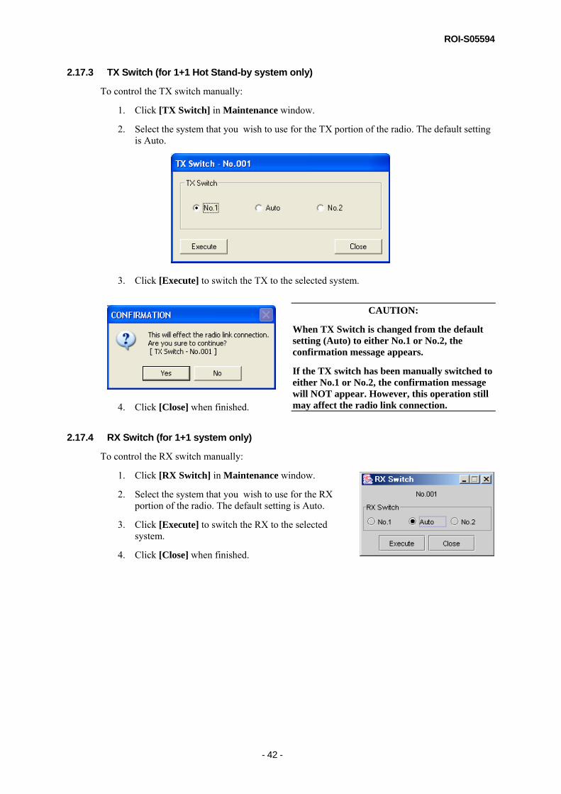
2.17.3 TX Switch (for 1+1 Hot Stand-by system only)
To control the TX switch manually:
1. Click [TX Switch] in Maintenance window.
2. Select the system that you wish to use for the TX portion of the radio. The default setting is Auto.
3. Click [Execute] to switch the TX to the selected system.
4. Click [Close] when finished.
2.17.4 RX Switch (for 1+1 system only)
To control the RX switch manually:
1. Click [RX Switch] in Maintenance window.
2. Select the system that you wish to use for the RX portion of the radio. The default setting is Auto.
3. Click [Execute] to switch the RX to the selected system.
4. Click [Close] when finished.
CAUTION:
When TX Switch is changed from the default setting (Auto) to either No.1 or No.2, the confirmation message appears.
If the TX switch has been manually switched to either No.1 or No.2, the confirmation message will NOT appear. However, this operation still may affect the radio link connection.

ROI-S05594
- 43 -
2.17.5 2 Port LAN Reset
To reset LAN Ports of LAN INTFC-S interface:
1. Click [2Port LAN Reset] in Maintenance window.
2. Select the port that you want to reset.
3. Click [Execute] to reset LAN ports.
4. Click [Close] when finished.
2.17.6 TX/RX Frequency
Display the RF transmitted frequency and consequently its pair receiving frequency. (See 2.18 Equipment Setup.)
2.17.7 Sub Band
Sub Band of ODU can be selected
To select Sub Band:
1. Click [Sub Band] in Maintenance window.
2. Select the type of Sub Band in the Sub Band list.
3. Click [Execute] to carry out the command.
4. Click [Close] when finished.
2.17.8 TX Mute status
TX power of the ODU is switched off when TX Mute is ON. This should be OFF in normal operation.
To change the TX Mute status:
1. Click [TX Mute] in Maintenance window.
2. Select ON/OFF depending on the desired state.
3. When you are setting to the opposite NE, you have to also select TX Release Time in the TX Mute Release Time list.
4. Click [Execute] to carry out the command.
5. Click [Close] when finished.

ROI-S05594
- 44 -
2.17.9 Loopback-1
This type loopback is created at the line input of E1..
To set the Loopback-1:
1. Click [Loopback-1] in the Maintenance window.
2. Select ON to activate the loopback.
3. Click [Execute] to apply the loopback.
4. Click [Close] when finished.
2.17.10 Loopback-2
This type loopback is created at the line output of E1.
To set the Loopback-2:
1. Click [Loopback-2] in the Maintenance window..
2. Select ON to activate the loopback.
3. Click [Execute] to apply the loopback.
4. Click [Close] when finished.

ROI-S05594
- 45 -
2.17.11 IF Loopback
This type loopback is created at the IF stage.
1. Click [IF LoopBack] in the Maintenance window.
NOTE
Switch ON maintenance mode first before executing IF Loopback.
2. Select ON to activate the loopback.
3. Click [Execute] to apply the loopback.
4. Click [Close] when finished.
2.17.12 CW (MOD Carrier) status
When doing frequency measurements, the CW should be turned ON to have an un-modulated signal. During normal operations this status should be OFF.
To change the CW (MOD Carrier) status:
1. Click [CW (MOD Carrier)] in Maintenance window.
NOTE
Switch ON maintenance mode first before executing CW.
2. Click ON/OFF depending on desired state.
3. Click [Execute] to carry out the operation.
4. Click [Close] when finished.

ROI-S05594
- 46 -
2.17.13 ATPC Manual
Use when an optional transmitting power is required when the ATPC is in operation. To set the ATPC Manual:
1. Click [ATPC Manual] in Maintenance window.
2. Select the whether to manually turn ON or OFF the ATPC manual and the ATPC manual power that will be transmitted in dB.
3. Click [Execute] to activate the new setting.
4. Click [Close] when finished.
2.17.14 Shift Frequency
The shift frequency function is used to select the type of shift frequency. This function is only available for 1+0 (4x2M) and 1+0 (20x2M) system configuration To select Shift Frequency:
1. Click [Shift Frequency] in Maintenance window.
2. Select the type of Shift Frequency in the Shift Frequency window.
3. Click [Execute] to activate the new setting.
4. Click [Close] when finished.
2.17.15 Antenna Alignment Mode (only available for the specific type of ODU)
The Antenna Alignment Mode function is used for extending the dynamic range of the RX LEVEL MONITOR (ODU). This function is only available for the specific type of ODU.
To set Antenna Alignment Mode:
1. Click [Antenna Alignment Mode] in Maintenance window.
2. Select ON/OFF
3. Click [Execute] to activate the new setting.
4. Click [Close] when finished.

ROI-S05594
- 47 -
2.18 Equipment Setup Main signal, Service signal, ODU and CTRL portion can be monitored and controlled in this window.
NOTE If each setting item of "Equipment Setup" is changed when equipment is in-service mode, the service will be interrupted.
2.18.1 Equipment Configuration window
To open the Equipment Configuration Monitor:
1. Select Configuration Equipment Setup in the NE-specific menu bar.
2. This window contains the setup information and control for the ODU and the IDU. The Equipment Setup window is shown below.
Equipment Setup window (1+0 System, 1+1 Hot Stand-by Configuration)

ROI-S05594
- 48 -
Equipment Setup window (1+1 Twin Path Configuration)

ROI-S05594
- 49 -
2.18.2 Setup
To setup the ODU and IDU parameters:
1. Click [Setup] in the Equipment Setup window.
Setup – Equipment Tab
Setup – Slot/LAN Tab
2. On both Equipment Tab and Slot/LAN Tab of Setup window, the configurable items are shown and described in the table below:

ROI-S05594
- 50 -
TX Frequency – sets the RF transmit frequency and consequently the RF received frequency of the ODU. If frequency Channel file is previously registered, frequency setting by Channel name is available. Refer to “Frequency Channel” screen shown below. Frame ID – used to synchronize the TX and RX frames of opposing NE’s in the hop. The frame ID can be set from 1 to 8. TX Power Control – method used by the ODU for power control functions can be set here. Either Automatic Transmit Power Control (ATPC) or Manual Transmit Power Control (MTPC) can be selected. System Configuration – This function Is available only for 1+1 systems Hot Stand-by or 1+0 (Expandable) configuration can be set using this function. Transmission Capacity – the main interface bit rate of IDU can be selected here. The available rates are 10Mbps, 20Mbps, 40Mbps and 80Mbps. 1+0(4x2M) can be set to only 10Mbps (FIX). 1+0(20x2M) can be set 10Mbps, 20Mbps, or 40Mbps. 1+0, 1+0 (Expandable) or 1+1 systems can be set using this function.
Equipment
Modulation– the modulation can be selected here. The available modulations are PQSK, and 16QAM. When the transmission capacity is set 80Mbps, you can select only 16QAM. Slot1 – sets the type of the module of Slot1.If this current setting is different from the inserted module type, you can click the reflect [◄] button and you can set the type to that of the inserted module. Slot2 – sets the type of the module of Slot2. If this current setting is different from the inserted module type, you can click the reflect [◄] button and you can set the type to that of the inserted module.
Slot/LAN
LAN INTFC-S – This function is available only when the current setting type of Slot2 is LAN INTFC-S. You can select Radio Mapping and bit rate for each port for 2-Port LAN interface module. Also the E1 (2Mbps main interface) assignment information is displayed. If you change the Transmission Capacity, the 2Port LAN setting will be cleared and you need to set it again.
3. Click [Execute] to apply the new set of values.
CAUTION:
Changing the TX/RX CH will interrupt the traffic.

ROI-S05594
- 51 -
2.18.3 Frequency Channel
1. Click [Browse] to locate the Channel plan file on the local hard disk.
2. Select Channel and click [OK], then TX and RX frequency corresponding to the channel will be set.
Frequency channel file format is csv, including channel name, TX frequency and RX frequency.
Examples
CH-1, 7442.000, 7603.000 CH-2, 7603.000, 7442.000
2.18.4 Editing the NE Name
To edit the NE name:
1. Click [NE Name] in Equipment Setup window.
2. Enter new NE name in the NE Name dialog box. A maximum of 32 characters can be used.
3. Click [Execute] to change to new name.
4. Click [Close] when finished.
2.18.5 Editing the Note for NE
To put an optional description on the current NE:
1. Click [Note] in Equipment Setup window.
2. Enter the optional description for the specific NE in the Note dialog box. A maximum of 100 characters can be used in this field
3. Click [Execute] when finished.
4. Click [Close] when finished.

ROI-S05594
- 52 -
2.19 Provisioning The main interface (MAIN INTFC), SC Assignment, MTPC and ATPC can be set in this window.
2.19.1 Provisioning window
To open the Equipment Configuration Monitor:
1. Select Configuration Provisioning in the NE-specific menu bar.
2. This window contains the setup information of the MTPC, ATPC, BER Alarm Threshold, Cluster ALM Setting (Input), AIS Activation, Main Channel Setting, SC Assignment and LAN INTFC-S. The Provisioning window is shown below.
Provisioning window (1+0 Configuration)

ROI-S05594
- 53 -
Provisioning window (1+1 Hot Stand-by Configuration)

ROI-S05594
- 54 -
Provisioning window (1+1 Twin Path Configuration)
Main Interface Setting

ROI-S05594
- 55 -
2.19.2 Manual Transmit Power Control (MTPC) Status
When the MTPC is selected over ATPC the buttons on this section will become sensitive and the MTPC parameters can be set. The MTPC has three (3) parameters:
• MTPC TX Power
• RX Threshold
• Additional Attenuation (Additional ATT) (for PASOLINK+ type ODU only)
The procedure for setting these parameters will be presented in this section.
2.19.2.1 MTPC TX Power
When the MTPC is in operation, the transmission power (dB) can be set using this function.
To set the maximum transmission power in MTPC:
1. Click [MTPC TX Power] in the Provisioning button.
2. Set the power (dB) in the ensuing window. You can either highlight the input field and enter the dB value using the keypad or use the arrows on the right-hand corner of the field to increase or decrease the value shown in the input field.
3. Click [Execute] to apply the maximum MTPC TX power.
4. Click [Close] when finished.
2.19.2.2 RX Threshold
Set the threshold value of the receiving level. When the received level converge on the preset value of the threshold the TX power is controlled by sending control signals in the Radio Frame Complementary Overhead (RFCOH).
To set the RX threshold:
1. Click [RX Threshold] in the MTPC status section of the Provisioning window.
2. Set the power (dBm) in the ensuing window. You can either highlight the input field and enter the dB value using the keypad or use the arrows on the right-hand corner of the field to increase or decrease the value shown in the input field.
3. Click [Execute] to apply the new preset value.
4. Click [Close] when finished.

ROI-S05594
- 56 -
2.19.2.3 Additional Attenuation (Additional ATT) (only available for the specific type of ODU) If the transmission length of the radio section is short, additional span attenuators can be set in the ODU. The additional attenuation can be set from 0 to 5 dB. This function is only available for the specific type of ODU.
To set the additional attenuation:
1. Click [Additional ATT] in the MTPC status section on the Provisioning window.
2. Set the attenuation (dB) in the ensuing window. You can either highlight the input field and enter the dB value using the keypad or use the arrows on the right-hand corner of the field to increase or decrease the value shown in the input field
3. Click [Execute] to apply the attenuation.
4. Click [Close] when finished.
2.19.3 Automatic Transmit Power Control (ATPC) Status
When the ATPC is selected over MTPC the buttons on this section will become sensitive and the ATPC parameters can be set. The ATPC has five (5) parameters:
• ATPC (MAX) (TX MAX Power)
• ATPC (MIN) (TX MIN Power)
• RX Threshold
• Additional Attenuation (Additional ATT) (only available for the specific type of ODU)
• ODU Alarm Mode
The procedure for setting these parameters will be presented in this section.
2.19.3.1 ATPC (MAX) (TX MAX Power)
When the ATPC is in operation, the maximum transmission power (dB) can be set using this function.
To set the maximum transmission power in ATPC:
1. Click [TX MAX Power] in the ATPC status section on the Provisioning window.
2. Set the power (dB) in the ensuing window. You can either highlight the input field and enter the dB value using the keypad or use the arrows on the right-hand corner of the field to increase or decrease the value shown in the input field.
3. Click [Execute] to apply the maximum ATPC TX power.
4. Click [Close] when finished.

ROI-S05594
- 57 -
2.19.3.2 ATPC (MIN) (TX MIN Power) When the ATPC is in operation, the minimum transmission power (dB) can be set using this function.
To set the minimum transmission power in ATPC:
1. Click [TX MIN Power] in the ATPC status section on the Provisioning window.
2. Set the power (dB) in the ensuing window. You can either highlight the input field and enter the dB value using the keypad or use the arrows on the right-hand corner of the field to increase or decrease the value shown in the input field.
3. Click [Execute] to apply the minimum ATPC TX power.
4. Click [Close] when finished.
2.19.3.3 RX Threshold
Set the threshold value of the receiving level. When the received level converge on the preset value of the threshold, the TX power is controlled by sending control signals in the Radio Frame Complementary Overhead (RFCOH).
To set the RX threshold:
1. Click [RX Threshold] in the ATPC status section on the Provisioning window.
2. Set the power (dB) in the ensuing window. You can either highlight the input field and enter the dB value using the keypad or use the arrows on the right-hand corner of the field to increase or decrease the value shown in the input field.
3. Click [Execute] to apply the new preset value.
4. Click [Close] when finished.
2.19.3.4 Additional Attenuation (Additional ATT) (only available for the specific type of ODU)
If the transmission length of the radio section is short, additional span attenuators can be set in the ODU. The additional attenuation can be set from 0 to 5 dB.
To set the additional attenuation:
1. Click [Additional ATT] in the ATPC status section of the Provisioning window.
2. Set the attenuation (dB) in the ensuing window. You can either highlight the input field and enter the dB value using the keypad or use the arrows on the right-hand corner of the field to increase or decrease the value shown in the input field
3. Click [Execute] to apply the attenuation.
4. Click [Close] when finished.

ROI-S05594
- 58 -
2.19.3.5 ODU Alarm Mode In cases wherein the ODU losses communication with the IDU due to failure of some sort, the response of the ODU can be preset using this function. Since the control function of the TX power is in the IDU, the ODU will be cut-off to this control when a failure in the communication between the ODU and the IDU occurs. In this case, the ODU either mutes the TX or Hold the current TX power, depending on the preset ODU ALM mode.
To set the ODU Alarm mode:
1. Click [ODU Alarm Mode] in the ATPC status section on the Provisioning window.
2. Select the action of the ODU in case of IDU communication failure. For ATPC, MAX Hold, MIN Hold or Hold mode is available.
3. Click [Execute] to apply the new setting.
4. Click [Close] when finished.
2.19.4 BER Alarm Threshold
The BER in the system monitors the DMR section. The figure below illustrates these sections.
2.19.4.1 High BER
To set the threshold for High BER:
1. Click [High BER] in the Provisioning window.
2. Select the preset BER value that will trigger.
3. Click [Execute] to apply the new setting.
4. Click [Close] when finished.
2.19.4.2 Low BER
To set the threshold for Low BER:
1. Click [Low BER] in the Provisioning window.
2. Select the preset BER value that will trigger.
3. Click [Execute] to apply the new setting.
4. Click [Close] when finished.

ROI-S05594
- 59 -
2.19.5 Cluster ALM Setting (Input)
This function enables or disables the Cluster Alarm setting.
1. Click [Cluster ALM 1/2] on the Provisioning window.
2. Select Enabled/Disabled depending on the desired state.
3. Click [Execute] to apply the new setting.
4. Click [Close] when finished.
2.19.6 AIS Activation
This function is used to set the AIS Activation Condition and AIS Activation Delay Time.
2.19.6.1 AIS Activation Condition
This function allows you to set whether AIS signal for main 1.5MB is by LOF, High BER or both alarm conditions.
To set the AIS Activation Condition:
1. Click [AIS Activation Condition] button on the Provisioning window.
2. Select LOF/LOF or High BER depending on the desired state.
3. Click [Execute] to apply the new setting.
4. Click [Close] when finished.
2.19.7 SW Priority
2.19.7.1 TX SW Priority The TX SW priority defines the channel that will be selected by the TX switch when both channels are normal.
Priority No.1: Priority is given to No.1 channel.
Non-priority: There is no priority.
This function is available for 1+1(HS) system only. 2.19.7.2 RX SW Priority
The RX SW priority defines the channel that will be selected by the RX switch when both channels are normal.
Priority No.1: Priority is given to No.1 channel.
Non-priority: There is no priority.
This function is available for 1+1 system only.

ROI-S05594
- 60 -
2.19.8 Main Interface Setting
2.19.8.1 Channel Usage Error Report This function is to enable or disable the Channel Usage Error Report function. This error is reported when 2MB bipolar signal is inputted into the channel chosen “Not Used”.
To set the Channel Usage Error Report:
1. Click [Channel Usage Error] on the Provisioning - Main Interface window.
2. Select Reported/Not Reported depending on the desired state.
3. Click [Execute] apply the new setting.
4. Click [Close] when finished.
2.19.8.2 AIS Received Report
This function is to enable or disable the AIS Received Report function.
To set the AIS Received Report:
1. Click [AIS Received Report] on the Provisioning - Main Interface window.
2. Select Reported/Not Reported depending on the desired state.
3. Click [Execute] apply the new setting.
4. Click [Close] when finished.
2.19.8.3 AIS Generated Report
This function is to enable or disable the AIS Generated Report function.
To set the AIS Generated Report:
1. Click [AIS Generated Report] on the Provisioning - Main Interface window.
2. Select Reported/Not Reported depending on the desired state.
3. Click [Execute] apply the new setting.
4. Click [Close] when finished.

ROI-S05594
- 61 -
2.19.8.4 AIS Received Condition Setting This function enables to set the type of AIS Received Condition.
To set the AIS Received Condition Setting:
1. Click [AIS Received Condition] on the Provisioning - Main Interface window.
2. Select Alarm/Status depending on the desired state.
3. Click [Execute] apply the new setting.
4. Click [Close] when finished.
2.19.9 SC Assignment
This function is to display the assigned interface type {LAN or RS-232C} of the available for user channels (DSC), and sets the type of directional interface for SC3 and SC4.
2.19.9.1 Direction (for 1+0 (Expandable) and 1+1 system only)
To set the type of directional interface for SC3 and SC4:
1. Click [Setting] in the SC Assignment section on the Provisioning window.
2. On the ensuing window, you will be able to select the type of directional interface for SC3 and SC4.
3. Click [Execute] to apply the new setting.
4. Click [Close] when finished.

ROI-S05594
- 62 -
2.19.10 LAN INTFC-S
Port Setting (LAN INTFC-S)
Port Switching – set the Port Switching when 2-Port LAN interface is used as {Port1-2 Shared/1 Port Only (Main) or Port1-2 Shared/1 Port Only (SC)}. Usage – specify the usage of each port. Speed & Duplex – set the type of the speed and the duplex of each port. The available types are AUTONEG (AUTO-MD1/MDIX),10M-HALF(MDI),10M-FULL(MDI),100M-HALF(MDI),100M-FULL(MDI),10M-HALF(MDIX),10M-FULL(MDIX),100M-HALF(MDIX) and 100M-FULL(MDIX). Flow Control – specify the Flow Control of each port. Collision Report – set the status of each port to report when some collision occurs.
Port Setting
Link Loss Forwarding– set enable of Link Loss Forwarding of each port. Port1-2 LAN >> 2M Framing – set the type of 2M Framing. This parameter is available when the following conditions are true 2-Port LAN >> Radio Mapping = Port1-2 Shared / 1 Port Only (Main) and 2Port LAN = 2Mbps in Equipment Setup window. Port1 LAN >> 2M Framing – set the type of 2M Framing. This parameter is available when the following conditions are true: {2-Port LAN >> Radio Mapping = Port1-2 Shared / 1 Port Only (Main) and 2Port LAN = 2Mbps}, or {2-Port LAN >> Radio Mapping=Port1-2 Shared / 1 Port Only (SC) and 2Port LAN=2Mbps} in Equipment Setup window.
Slot/LAN
Port2 LAN >> 2M Framing – set the type of 2M Framing This parameter is available when 2-Port LAN >> Radio Mapping = Port1-2 Separated (Main) and 2Port LAN =2Mbps in Equipment Setup window.

ROI-S05594
- 63 -
2.20 Link Performance Monitor The following performance items can be monitored according to the parameters expressed in the G.826 recommendation:
Out of Frame Second (OFS) – the total number of seconds the "out of frame" condition is generated in 15 minute-blocks.(OFS is applied to the Total only)"
Errored Second (ES) – the cumulative time in which more than one B1 error pulse per second was detected
Severely Errored Second (SES) – the cumulative time in which the BER of one-second period exceeded 10E-3.
Unavailable Second (UAS) –the cumulative time in which the unit remained inoperative Background Block Error (BBE) - the sum of the B1 background block error
Red color in Performance Monitor window indicates the occurrence of performance items exceeding the threshold value. The threshold values can be set in Threshold window. The detailed daily performance data can be viewed by clicking [Detail].
2.20.1 Viewing Summary Link Performance Monitor
To view Summary Link Performance Monitor:
Click Performance Monitor Link Performance Monitor in the NE-specific menu bar of the target NE that you intend to monitor.
Summary Link Performance Monitor window

ROI-S05594
- 64 -
2.20.2 Threshold Setting
To set the threshold values:
1. Click [Threshold] in the Summary Link Performance Monitor window
Summary Link Performance Monitor Threshold
2. Select the performance item that is to be configured in the table shown above. The G.826 measuring parameters become available for setting when selected. The arrow buttons on the left-hand side of the field indicates this.
3. Set the value when the alarm occurred (Occur) and when the alarm was resolved (Recover) in the appropriate field. The measuring parameters will initiate an alarm status indication when it reaches the alarm occurrence (occur) value or an alarm clear status when it reaches the resolution (recover) value set in the threshold table.
4. Click [Execute] to activate the new settings.
5. Click [Close] when finished.
ROI-S05594
- 65 -
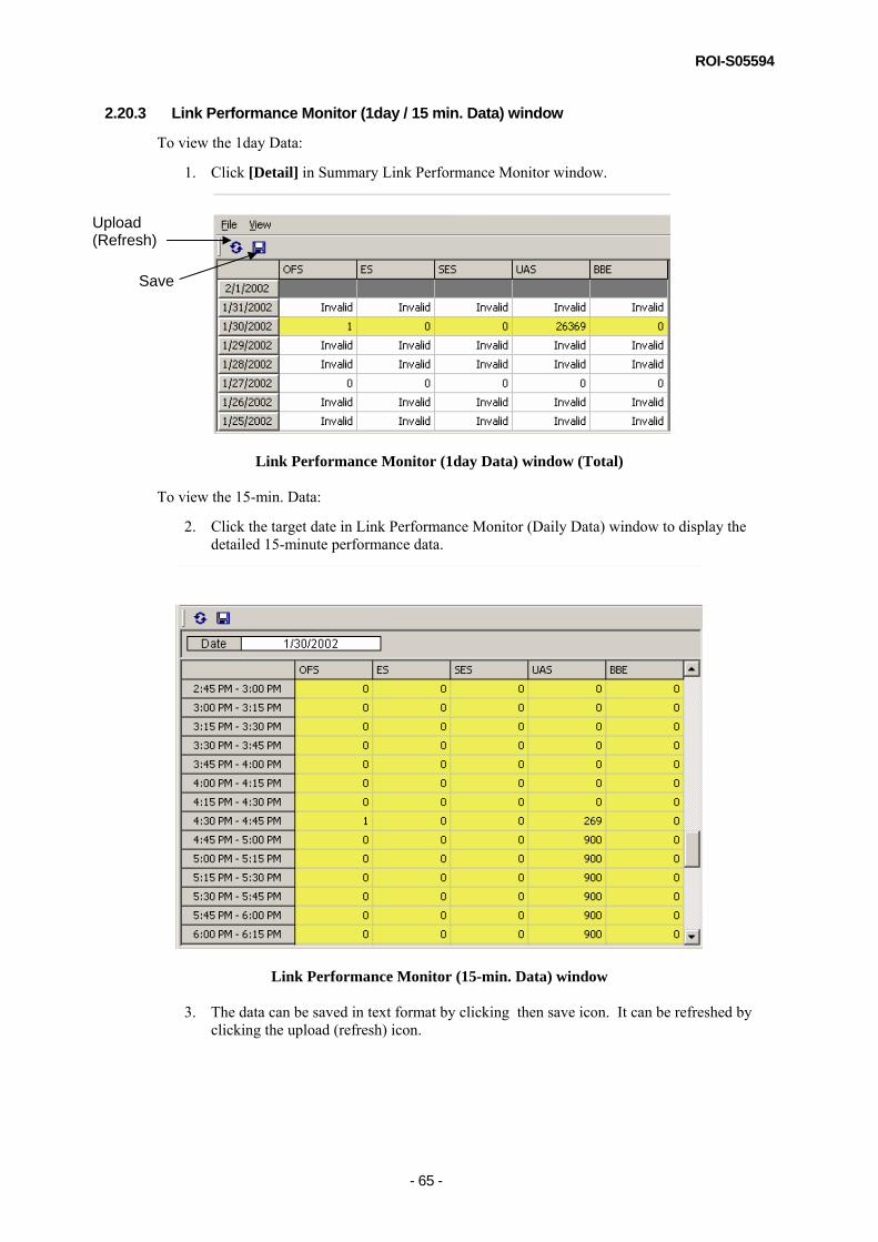
2.20.3 Link Performance Monitor (1day / 15 min. Data) window
To view the 1day Data:
1. Click [Detail] in Summary Link Performance Monitor window.
Link Performance Monitor (1day Data) window (Total)
To view the 15-min. Data:
2. Click the target date in Link Performance Monitor (Daily Data) window to display the detailed 15-minute performance data.
Link Performance Monitor (15-min. Data) window
3. The data can be saved in text format by clicking then save icon. It can be refreshed by clicking the upload (refresh) icon.
Save
Upload (Refresh)

ROI-S05594
- 66 -
2.21 Remote Network Monitoring (RMON) Remote Network Monitoring (RMON) function can monitor the signal through the LAN port, both LINE-side (the port on the NE) and DMR side. RMON can count the number of received or transmitted packets and packets errors. These items are then displayed in the PNMT.
The following RMON items can be monitored:
RX Unicast Pkts – the total number of unicast packets received. This item measures from 64 octets to 1536 octets. RX Broadcast Pkts – the total number of packets received that were directed to the broadcast address. This item measures from 64 to 1536 octets in length. RX Multicast Pkts – the total number of packets received that were directed to a multicast address. This item measures from 64 to 1536 octets in length. RX Pause Pkts – the total number of packets received that were paused. RX CRC Errors – the total number of packets received that detected FCS error. This item measures from 64 to 1536 octets in length. RX Align Errors – the total number of packets received that detected Alignment error. This item measures from 64 to 1536 octets in length. RX Symbol Errors – the total number of packets received that detected Symbol error. This item measures from 64 to 1536 octets in length. RX Undersize Pkts – the total number of good packets received that were less than 64 octets in length. RX Fragments – the total number of packets (Including bad packets) received that were less than 64 octets in length. RX Pkts 64 – the total number of packets (Including bad packets) received that were 64 octets in length. RX Pkts 65-127 – the total number of packets (Including bad packets) received that were between 65 and 127 octets in length. RX Pkts 128-255 – the total number of packets (Including bad packets) received that were between 128 and 255 octets in length. RX Pkts 256-511 – the total number of packets (Including bad packets) received that were between 256 and 511 octets in length. RX Pkts 512-1023 – the total number of packets (Including bad packets) received that were between 512 and 1023 octets in length. RX Pkts 1024-1536 – the total number of packets (Including bad packets) received that were between 1024 and 1536 octets in length. RX Pkts 1537-MAX – the total number of good packets received that were between 1537 and 1916 octets in length. RX Jabbers – the total number of packets received (Including bad packets) that were longer than 1537 octets. TX Unicast Pkts – the total number of unicast packets transmitted. This item measures from 64 to 1916 octets in length. TX Broadcast Pkts – the total number of packets transmitted that were directed to the broadcast address. This item measures from 64 to 1916 octets in length. TX Multicast Pkts – the total number of packets transmitted that were directed to a multicast address. This item measures from 64 to 1916 octets in length. TX Pause Pkts – the total number of packets transmitted that were paused.
RMON
TX Total Collisions – the total number of collisions when it is transmitting.

ROI-S05594
- 67 -
NOTE:
If an item causes overflow, ‘+’ will be shown in front of the number.
If an item is invalid, ‘*’ will be shown in front of the number. When the total number is imperfect, it will be shown as invalid.
During maintenance mode, an item will be shown with maintenance color (yellow as default).
2.21.1 Viewing RMON LAN INTFC-S [Current]
This window contains the latest 15-minute data (15-min) and to the current day’s total data (Daily) for all RMON items.
To view RMON LAN INNTFC-S [Current] Monitor:
Select Performance Monitor RMON LAN INTFC-S [Current] in the NE-specific menu bar of the target NE that you intend to monitor.
RMON LAN INTFC-S [Current] window
This data can be refreshed by selecting File Refresh menu or clicking on Refresh icon.

ROI-S05594
- 68 -
2.21.2 Viewing RMON LAN INTFC-S [15-min]
This window contains the total 15-minute data in 24 hours for all RMON items.
To view RMON LAN INTFC-S [15-min] Monitor:
1. Select Performance Monitor RMON LAN INTFC-S [15-min] in the NE-specific menu bar of the target NE that you intend to monitor.
RMON LAN INTFC-S [15-min] window
2. This data can be saved by selecting File Save All Data menu or clicking on Save All Data icon. The default file name that it will be saved to is “15min-s.rmon”.
3. This data can be refreshed by selecting File Reload menu or clicking on Reload icon.
4. This data can be sorted by port or Item by selecting Sort Port Sort or Item Sort menu.
5. The viewing RMON items can be selected with the Select window.
To view the Select window:
Select Select Select menu.

ROI-S05594
- 69 -
RMON LAN INTFC-S [15-min] Select window
You can select/deselect the items that you want to be shown by clicking the list [ ] icon and selecting from the pull down menu {Select All / Clear All}, Package control for all the item(s) can be carried out for individual Port.

ROI-S05594
- 70 -
2.21.3 Viewing RMON LAN INTFC-S [Daily]
This window contains the daily data in 7 days for all RMON items.
To view RMON LAN INNTFC-S [Daily] Monitor:
1. Select Performance Monitor RMON LAN INTFC-S [Daily] in the NE-specific menu bar of the target NE that you intend to monitor.
RMON LAN INTFC-S [Daily] window
1. This data can be saved for all items by selecting File Save All Data menu or clicking on Save All Data icon. The default file name is “daily-s.rmon”.
2. This data can be refreshed by selecting File Reload menu or clicking on Reload icon.
3. This data can be sorted by port or Item by selecting Sort Port Sort or Item Sort menu.
4. The viewing RMON items can be selected with the Select window.
To view the Select window:
Go to Select Select menu.

ROI-S05594
- 71 -
RMON LAN INTFC-S [Daily] Select window
You can select the items that you want to be shown by clicking on the list [ ] button and selecting from the pull-down menu {Select All / Clear All}. Package control of all the item(s) can be carried out for individual Port.

ROI-S05594
- 72 -
2.22 NE Stored Log NE Stored Log window displays the date/time when the event data was received, item, and status.
2.22.1 NE Stored Log monitor
1. Click on [NE Stored Log] in the NE-specific menu bar of the target NE that you intend to monitor.
2. A message window showing the progress of the uploading of the NE Stored Log data will appear on the screen. Wait until the PNMT finishes the uploading of the data. The progress window will automatically close once the uploading is completed.
3. The NE Stored Log View will be displayed. The event log is presented in a table form showing the date of the event, the item that triggered the event and the status change.
4. Sorting is possible for every column in NE Stored Log window.
5. The date shown in the NE Stored Log window will be the format set up by OS.
6. The data can be refreshed by clicking on the upload (refresh) icon.

ROI-S05594
- 73 -
2.23 Version Tab The inventory information of the equipment can be viewed using this function.
2.23.1 Version Monitor
To display the version of the equipment:
1. Select the Version tab in PNMT main window.
2. The Version window shows the Code No., Date of Manufacture, Serial No., Hardware Type (for ODU only) and Software Version of the equipment.
Version window (1+0 Configuration)
Version window (1+1 Configuration)

ROI-S05594
- 74 -
2.24 License import 2.24.1 License import
To update the license file:
1. Go to Help License in menu bar on PNMT main window.
2. Import License Wizard will appear on screen. Click [Next] to continue.

ROI-S05594
- 75 -
3. Click […] to locate the new license key file.
4. Indicate a License key file (i.e. License.key) that will be associated to PNMT. Select a License key file and click [Open] to continue.

ROI-S05594
- 76 -
5. After verifying the path to License key file is correct, click [Next] to proceed.
6. The progress of checking license file will be displayed. If no error is encountered in checking of the license file, click [Next] when the button becomes available.

ROI-S05594
- 77 -
7. Verify the contents of license that you applied.
8. Click [Finish] in ensuing window to complete applying license.