THIS IS 100 200 300 400 500 Chp. 15a Chp. 15b Chp. 15cChp. 16a Chp. 16b Leaders.

ww.sciencedirect.com
i n t e r n a t i o n a l j o u r n a l o f h y d r o g e n en e r g y 4 0 ( 2 0 1 5 ) 1 1 6 3 3e1 1 6 4 0
Available online at w
ScienceDirect
journal homepage: www.elsevier .com/locate/he
Parametric evaluation of a micro-CHP unit withsolid oxide fuel cells integrated with oxygentransport membranes
Jakub Kupecki*, Janusz Jewulski, Konrad Motylinski
Thermal Processes Department, Institute of Power Engineering, Warsaw, Poland
a r t i c l e i n f o
Article history:
Received 30 January 2015
Received in revised form
22 March 2015
Accepted 25 March 2015
Available online 17 April 2015
Keywords:
Micro-CHP
SOFC
Modeling
Oxygen membranes
CCS
* Corresponding author. Tel.: þ48 7979 05 14E-mail address: [email protected]
http://dx.doi.org/10.1016/j.ijhydene.2015.03.127
0360-3199/Copyright © 2015, The Authors. Publishe
CC BY-NC-ND license (http://creativecommons.org
a b s t r a c t
Paper presents parametric evaluation of a modified design of a conceptual micro-combined
heat and power unit (micro-CHP) with solid oxide fuel cells. The system incorporates ox-
ygen transport membranes to supply high purity oxygen for post-combustion of lean fuel
leaving the SOFC stack. The concentrations of CO2 in the flue gases leaving the system,
approaches 99% (on dry gas basis). High temperature oxygen transport membranes, made
of perovskite materials, enable oxygen permeation rate exceeding 6 Nml/(cm2 min). The
oxygen permeation is strongly related to the ratio of oxygen partial pressures at the
retentate and permeate sides. Results of a parametric evaluation of the system, including
the analysis of effects of membrane characteristics on the electrical efficiency, are pre-
sented and discussed. Oxygen transport membranes require high pressure at the feed site,
therefore an increase of auxiliary power consumption should be expected to achieve high
oxygen flow through the membrane. Electrical penalty in range 6e12%-point was observed,
in comparison with a conventional micro-CHP system without oxy-combustion. These
numbers are often quoted for large power systems operating in a CCS-ready mode with
state-of-the-art oxygen separation methods such as pressure swing adsorption (PSA).
Electrical efficiency of the system discussed in this paper was evaluated and effects of
oxygen permeation rate on the electrical efficiency were analyzed.
Copyright © 2015, The Authors. Published by Elsevier Ltd on behalf of Hydrogen Energy
Publications, LLC. This is an open access article under the CC BY-NC-ND license (http://
creativecommons.org/licenses/by-nc-nd/4.0/).
Introduction
In solid oxide fuel cells (SOFC), electric current is generated
with the highest known efficiency due to the direct electro-
chemical oxidation of fuel. Contrary to existing well-
established combustion processes, partially utilized fuel and
oxidant streams exiting fuel cell stack are separated when
leaving the anodic and cathodic compartments. When the
partially utilized fuel is combusted in high purity oxygen, CO2
7; fax: þ48 22 6428 378.l (J. Kupecki).
d by Elsevier Ltd on behalf of
/licenses/by-nc-nd/4.0/).
and steam are virtually the only products of combustion.
Using such technique the expensive separation process of CO2
from flue gases can be avoided. Additionally, the volumetric
flow of exhausts is visibly lower due to the elimination of ni-
trogen in oxy-combustor.
Only 15%e30% of the SOFC inlet fuel is oxy-combusted in a
post-combustor. In addition to CO2 capture, the additional
process design benefits include: (a) combustion heat available
for the process and (b) the reduced flow rates of the exhaust
gas stream. Numerous system configurations have already
Hydrogen Energy Publications, LLC. This is an open access article under the

i n t e rn a t i o n a l j o u r n a l o f h y d r o g e n en e r g y 4 0 ( 2 0 1 5 ) 1 1 6 3 3e1 1 6 4 011634
been considered for the power plants with bothMCFC [1,2] and
SOFC [3] fuel cell stacks. A recent comparison study of three
different SOFC based hybrid systems has shown energy effi-
ciency penalty of about 3e4% relative to a reference system
without CO2 capture [4]. Performance of the oxy-CHP unit
strongly depends on the characteristics of oxygen separation
process, specially the oxygen permeation rate and the
permeation selectivity. Among several competing technolo-
gies, cryogenic process, mixed ionic electronic conducting
membranes (MIEC) and oxygen enriched airmembranes (OEA),
such as polymeric membranes, are consider to be the most
promising. The permeation selectivity of over 20 (O2 over N2) is
targeted for a membrane based approach to become compet-
itivewith cryogenic techniques for hybrid CO2 capture systems
[5]. The MIEC membranes offer close to 100% pure oxygen
steam. The choice of a specific membrane composition de-
pends on the membrane design architecture and operating
conditions of the membrane [6]. The over 20 years progress in
development of ceramic membranes for oxygen separation
from air is targeting replacement of the energy intensive,
conventional air separation technologies [7]. The chemical and
physical stability of the membrane and high permeation rates
of oxygen are the most important selection factors.
Dense and thick ceramic MIEC membranes, such as LSCF
and BSCF perovskites, exhibiting oxygen permeation of over
2.5 Nml/(cm2 min) at 1123 K [8], are currently considered as
candidates for the oxy-combustion process. A significant po-
tential for the order of magnitude increase in the O2 perme-
ation rates has already been shown, using porous support and
thin membrane approach [9].
Oxy-fuel power plants configurations based on OTM
membranes have been studied for the BSCF tubular mem-
brane module, using Aspen HYSYS 8.2 process simulator and
oxygen transport properties derived from the experimental
study [10]. The fidelity of the process modeling studies is
limited by the approximation of OTM engineering details (e.g.,
membrane shape, geometric structure of the ASU, flow
configuration, membrane porous support, dependence of
ionic transport on the oxygen chemical activity gradients)
influencing the actual performance of the ASU [11].
In a recent study of a hybrid 120 kW SOFC system inte-
grated with OTM module in a “three-end design”, it has been
shown that electric efficiency 2.5%-point lower than in the
system without CO2 capture is achievable [12]. In the same
study, SOFC system integrated with cryogenic ASU, operating
under the same conditions, has shown 1%-point lower electric
efficiency when compared to OTM module.
The competitiveness of CO2 capture from the industrial
scale 5 MWe hybrid CHP/SOFC systems was recently investi-
gated showing that, such systems with capture are more
competitive at the CO2 price higher than 40e50 $/tCO2 [13]. The
CO2 capture from distributed energy systems offers a signifi-
cant cost reduction potential in the long term [14].
Modeling of micro-power systems with SOFCsoxygen transport membranes
There are two alternative approaches for the integration of
oxygenOTMmembraneswith the oxy-combustion of partially
utilized fuel outlet stream, leaving the SOFC stack. In the first
approach, oxygen is generated in a membrane module and
supplied to post-combustor (“three-end design”). The BSCF
membrane was proposed for the “three-end” oxy-fuel process
design [15]. In the alternative approach, partially utilized fuel
stream is directly supplied to membrane module permeate
compartment (“four-end design”). There are additional re-
strictions placed on the chemical stability of membrane in the
“four-end design” module due to direct contact of membrane
with the fuel, severely limiting the membrane material
choices. Typical OTM membranes, such as SrCo0.8Fe0.2O3�d
(SCF), Ba0.5Sr0.5Co0.8Fe0.2O3�d (BSCF) and
La0.6Sr0.4Co0.2Fe0.8O3�d (LSCF) have limitations for the opera-
tion under large O2 chemical potential gradients and in con-
tact with CO2/H2O atmosphere. Alternative membrane
materials such as CGOCe0.9Gd0.1O1.95�d (CGO) are investigated,
showing up to a 100-fold increase in the O2 permeation rate
when methane-rich fuel stream is supplied to the permeate
side of the membrane [16].
In general, dense ceramicmembranes are often considered
as a potential source of high purity (over 99.5%) oxygen.
Membranes made of Ba0.5Sr0.5Co0.8Fe0.2O3�d (BSCF) perov-
skites are mixed ionic and electronic conductors [17]. They
operate at elevated temperature, often exceeding 800 �C [18].
Oxygen permeation for a circular membrane is defined by
Eq. (1), which correlates oxygen permeation rate JO2 [Nml/cm2/
min] with ionic and electronic conductivities (si and se), Far-
aday's constant (F), universal gas constant (R), characteristic
and actual thickness (LC and L), diameter (d), operating tem-
perature (T) and partial pressure of oxygen in the feed and
permeate sides:
JO2¼ � 1
1þ�
2LCL
� RT4F2L
ZlnpIIO2lnpI
O2
selsi
sel þ sid ln
�pO2
�(1)
Formula 1 is known as the modified Wagner equation.
For the BSCF perovskites which exhibit much larger elec-
tronic than ionic conductivity equation (1) reduces to Eq. (2).
JO2¼ � 1
1þ�
2LCL
� RT4F2L
ZlnpIIO2lnpI
O2
sid ln�pO2
�(2)
For the purpose of system-level studies, oxygen perme-
ation can be expressed in a simplified form:
JO2¼ siRT
16LF2ln
pIO2
pIIO2
!(3)
Oxygen permeation rate is related to the thickness of
membrane, operating temperature and partial pressure of
oxygen in the feed and permeate sides. In a three-end
configuration, pressurization of the feed side is required to
achieve high oxygen permeation rates.
Examples of dense circular and tubular BSCF
(Ba0.5Sr0.5Co0.8Fe0.2O3ed) membranes fabricated by Ceramic
Department (CEREL) of the Institute of Power Engineering are
shown in Fig. 1.
Experimental data of these membranes were used as
default values in the current study.

i n t e r n a t i o n a l j o u r n a l o f h y d r o g e n en e r g y 4 0 ( 2 0 1 5 ) 1 1 6 3 3e1 1 6 4 0 11635
Description of the system
Micro combined heat and power units (micro-CHP) with solid
oxide fuel cells (SOFC) offer a great promise for distributed
power generation. Systems can be tailored to a specific locally
available fuel [19]. Configurations which are currently
considered allow to satisfy demand for electricity and hot
water of a typical single-family detached dwelling. Recent
advances in solid oxide fuel cells allow to achieve electrical
efficiency of a system above 43% (LHV-based) [20], including
systems fed by alternative fuels such as biogas [21].
A new approach has been proposed to reduce emissions
from these power units. Incorporation of oxygen transport
membranes (OTM) in SOFC-based power system allows to
establish carbon capture and sequestration ready (CCS-ready)
configurations [22], with efficiency penalty lower than 10%-
points in comparison with no-CCS systems. High temperature
oxygen transport membranes enable generation of oxygen
stream with purity exceeding 99% [9]. Post-combustor located
downstream of the SOFC stack can therefore operate in oxy-
mode, achieving high CO2 concentration in the exhausts
leaving the system.
Micro-combined heat and power units with solid oxide fuel
cells are often listed among several technologies offering a
cost-effective solution for distributed energy systems based
on local fuel resources. The inherently high electrical effi-
ciency justifies this statement. Such systems enable several
modifications to meet particular requirements in terms of the
operating functionality. In general, one of three parameters
can be selected for maximization: (I) electric power, (II) ther-
mal power, or (III) the electric efficiency. Depending on the
operating mode, working conditions of the system and its
components change. Strong effects of the off-design operation
on the electrical efficiency are usually observed.
The currently considered power system presented in Fig. 2
incorporates several major components:
a. solid oxide fuel cell stack in which the electrochemical
oxidation of fuel takes place,
Fig. 1 e BSCF membranes fabricated by institute of power
engineering, ceramic department CEREL.
b. fuel processor - steam reformer, which enables conversion
of raw fuel to hydrogen richmixture supplied to the anodic
compartments of the fuel cell stack,
c. recirculation blower, which serves as a machine enabling
increase of the overall fuel utilization in electrochemical
reaction, and supplies steam of prevention of carbon for-
mation and deposition,
d. air blower, which forces the flow of air delivered to the
cathode of SOFC stack,
e. post-combustor, which allows to recover the remaining
chemical energy of lean fuel leaving the SOFC stack,
f. draft fan, which is a part of venting system and DC/AC
inverter, which changes direct current (DC) to alternating
current (AC).
Additionally the system is equipped with regulation and
control sub-system, and balance of plant components (not
shown in Fig. 2).
Heat can be recovered from the system by using a hot
utility water preparation module such as storage tank or for
preheating water supplied to a conventional condensing
boiler.
This particular configuration based on a high temperature
recirculation blower allows to increase fuel utilization in the
SOFC stack in order to achieve high electrical efficiency.
Additionally, recirculation of anodic off-gas allows to supply
steam to the fuel processor. Sufficient steam to carbon ratio
(S/C) can be therefore maintained to prevent solid carbon
formation and deposition in the steam reformer and in anodic
compartments of the stack.
The recently proposed concept of the systemwas based on
replacing the conventional post-combustion with a oxy-
combustor. Such modification required to supply oxygen
from an external source. For that reason module of oxygen
transport membranes (OTM) was considered. With this
change, a modified post-combustor has to be used to allow
operationwith oxygen-rich oxidizer. A few alternative designs
of oxy-combustors, specifically for micro-scale systems have
been under development at the Institute of Power Engineering
in frame of European Project SOFCOM.
In the conventional system, combustion of anodic lean-
fuel is done using depleted air leaving cathode compart-
ments of the SOFC stack. Gas typically contains 12e18% of
oxygen, depending on the oxidant utilization factor in fuel cell
stack. Large flow of air, typical for oxidant utilization in range
0.20e0.40 assures complete combustion of combustible gases
leaving anodic side of a stack. Use of high purity oxygen
delivered from external source such as OTM membranes al-
lows to substantially reduce volumetric flow of oxidant for
post-combustion process. This however can lead to several
critical issues, including improper mixing of fuel and oxidant,
high combustion temperature, and aerodynamic instability of
the process. Such problems were however not considered in
the current study.
There are several additional components necessary for
integration of the oxygen transport membranes in a power
unit. Membranes require pressurization in order to achieve
high permeation rates. Additionally, air supplied to the feed
side of a membrane requires preheating to high temperature,
relevant to the stack operating conditions.

Fig. 2 e A conventional micro-CHP system with solid oxide fuel cells.
i n t e rn a t i o n a l j o u r n a l o f h y d r o g e n en e r g y 4 0 ( 2 0 1 5 ) 1 1 6 3 3e1 1 6 4 011636
Depleted air leaving the membrane module can be
expanded to recover remaining energy. The modified config-
uration of the unit is presented in Fig. 3.
Changes in the system outline (Fig. 3) were introduce to
accommodate several issues related to simultaneous opera-
tion of SOFC stack and membrane module within the same
power unit. Such configuration is a result of conceptual anal-
ysis of optional configurations of the OTM-micro-CHP unit.
Evaluation of the system
Two numerical simulation platforms were built to evaluate
performance of the conventional and modified configuration
of the micro-CHP unit. Thorough evaluation of the reference
system was done previously, and current work was focused
on analysis of a power unit with integrated oxygen transport
membranes.
Models were implemented in Aspen HYSYS 8.2 to allow
simulation of stationary operation at the nominal and off-
design conditions. The purpose of modeling activities was
Fig. 3 e Micro-CHP system with solid
to evaluate sensitivity of the system to change of membrane
properties and operating conditions. Two scenarios were
under consideration: (I) system with one particular type of
membranes in oxygen generation module, (II) module with
interchangeable membranes to achieve higher oxygen
permeation rates. First option requires modification of the
feed side pressure to adjust pressure level to obtain higher
permeation rates. Oxygen permeation of the membrane was
influence only by the pressure at the feed side, since con-
stant operating temperature was assumed. Second option
meant operation at nominal conditions and replaceable
membranes (exhibiting different permeation rates). The
second scenario considered in the study was based on an
assumption that membranes with different performance at
the nominal working conditions can be integrated with
micro-CHP unit.
Evaluation of oxygen transport membranes was done at
reference testing conditions. For the purpose of current
work, reference state with absolute pressure 1 bar and
0.03 bar in the feed and permeate sides, respectively, was
considered. Three membranes were selected with
oxide fuel cells and OTM module.
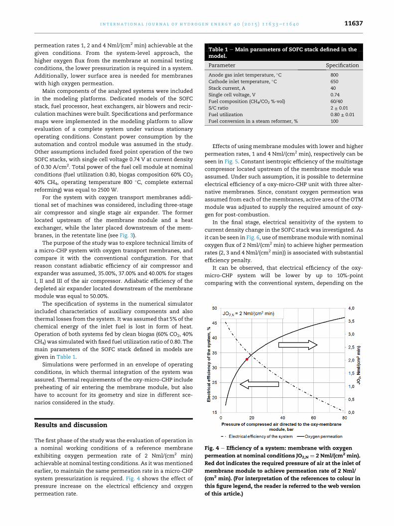
Table 1 e Main parameters of SOFC stack defined in themodel.
Parameter Specification
Anode gas inlet temperature, �C 800
Cathode inlet temperature, �C 650
Stack current, A 40
Single cell voltage, V 0.74
Fuel composition (CH4/CO2 %-vol) 60/40
S/C ratio 2 ± 0.01
Fuel utilization 0.80 ± 0.01
Fuel conversion in a steam reformer, % 100
i n t e r n a t i o n a l j o u r n a l o f h y d r o g e n en e r g y 4 0 ( 2 0 1 5 ) 1 1 6 3 3e1 1 6 4 0 11637
permeation rates 1, 2 and 4 Nml/(cm2 min) achievable at the
given conditions. From the system-level approach, the
higher oxygen flux from the membrane at nominal testing
conditions, the lower pressurization is required in a system.
Additionally, lower surface area is needed for membranes
with high oxygen permeation.
Main components of the analyzed systems were included
in the modeling platforms. Dedicated models of the SOFC
stack, fuel processor, heat exchangers, air blowers and recir-
culationmachines were built. Specifications and performance
maps were implemented in the modeling platform to allow
evaluation of a complete system under various stationary
operating conditions. Constant power consumption by the
automation and control module was assumed in the study.
Other assumptions included fixed point operation of the two
SOFC stacks, with single cell voltage 0.74 V at current density
of 0.30 A/cm2. Total power of the fuel cell module at nominal
conditions (fuel utilization 0.80, biogas composition 60% CO2
40% CH4, operating temperature 800 �C, complete external
reforming) was equal to 2500 W.
For the system with oxygen transport membranes addi-
tional set of machines was considered, including three-stage
air compressor and single stage air expander. The former
located upstream of the membrane module and a heat
exchanger, while the later placed downstream of the mem-
branes, in the retentate line (see Fig. 3).
The purpose of the study was to explore technical limits of
a micro-CHP system with oxygen transport membranes, and
compare it with the conventional configuration. For that
reason constant adiabatic efficiency of air compressor and
expander was assumed, 35.00%, 37.00% and 40.00% for stages
I, II and III of the air compressor. Adiabatic efficiency of the
depleted air expander located downstream of the membrane
module was equal to 50.00%.
The specification of systems in the numerical simulator
included characteristics of auxiliary components and also
thermal losses from the system. It was assumed that 5% of the
chemical energy of the inlet fuel is lost in form of heat.
Operation of both systems fed by clean biogas (60% CO2, 40%
CH4) was simulatedwith fixed fuel utilization ratio of 0.80. The
main parameters of the SOFC stack defined in models are
given in Table 1.
Simulations were performed in an envelope of operating
conditions, in which thermal integration of the system was
assured. Thermal requirements of the oxy-micro-CHP include
preheating of air entering the membrane module, but also
have to account for its geometry and size in different sce-
narios considered in the study.
Fig. 4 e Efficiency of a system: membrane with oxygen
permeation at nominal conditions JO2,N ¼ 2 Nml/(cm2 min).
Red dot indicates the required pressure of air at the inlet of
membrane module to achieve permeation rate of 2 Nml/
(cm2 min). (For interpretation of the references to colour in
this figure legend, the reader is referred to the web version
of this article.)
Results and discussion
The first phase of the study was the evaluation of operation in
a nominal working conditions of a reference membrane
exhibiting oxygen permeation rate of 2 Nml/(cm2 min)
achievable at nominal testing conditions. As it wasmentioned
earlier, to maintain the same permeation rate in a micro-CHP
system pressurization is required. Fig. 4 shows the effect of
pressure increase on the electrical efficiency and oxygen
permeation rate.
Effects of using membranemodules with lower and higher
permeation rates, 1 and 4 Nml/(cm2 min), respectively can be
seen in Fig. 5. Constant isentropic efficiency of the multistage
compressor located upstream of the membrane module was
assumed. Under such assumption, it is possible to determine
electrical efficiency of a oxy-micro-CHP unit with three alter-
native membranes. Since, constant oxygen permeation was
assumed from each of themembranes, active area of the OTM
module was adjusted to supply the required amount of oxy-
gen for post-combustion.
In the final stage, electrical sensitivity of the system to
current density change in the SOFC stack was investigated. As
it can be seen in Fig. 6, use ofmembranemodulewith nominal
oxygen flux of 2 Nml/(cm2 min) to achieve higher permeation
rates (2, 3 and 4 Nml/(cm2 min)) is associated with substantial
efficiency penalty.
It can be observed, that electrical efficiency of the oxy-
micro-CHP system will be lower by up to 10%-point
comparing with the conventional system, depending on the
Fig. 5 e Efficiency of a system: with three different
membranes with permeation rates at nominal conditions
1, 2 and 4 Nml/(cm2 min).
i n t e rn a t i o n a l j o u r n a l o f h y d r o g e n en e r g y 4 0 ( 2 0 1 5 ) 1 1 6 3 3e1 1 6 4 011638
electrical load. Increase of auxiliary power consumption is
related to compression power, when OTM module is pres-
surized to achieve permeation rate of oxygen of 4 Nml/
(cm2 min). Elevated oxygen flow allows to reduce active area
of membranes and increase thermal integration of the sys-
tem. In the study, it was assumed, that thermal losses account
to 5% of the chemical energy of fuel at the inlet to the system.
Under such assumption, oxygen permeation lower than
0.5 Nml/(cm2 min) requires much larger membrane area,
Fig. 6 e Electrical efficiency of OTM-micro-CHP and
conventional micro-CHP as a function of current density.
which cannot be thermally integrated with the system. In
such case external heat source might be required.
Numerical simulators allowed defining parameters of
streams in both configurations. Examples of such data are
shown in Tables 2 and 3 for current density in the fuel cell
stack equal to 0.225 A/cm2. It should be noted that in the
conventional system, gases exiting the SOFC stack are com-
bined, enter the post combustor, and eventually only one
stream of gases is leaving the system (stream 11). In the
modified OTM-micro-CHP unit, three streams leave the sys-
tem (12,13 and 19). Where stream 12 are products of com-
bustion in the oxy-combustor, stream 13 is the direct outlet of
cathodic compartments of the SOFC stack, and stream 19 is
the depleted air leaving the membrane module. From these
streams, the remaining energy is recovered for preheating of
gases entering the system, and additionally depleted air
leaving the OTMmodule is expanded to reduce pressure down
to 1.01 bar. Moreover, mass flows in streams 12,13 and 19 are
related to operational characteristics of both the fuel cell stack
and oxygen membranes. Finally, the current working condi-
tions in both components affect the composition of gases,
temperature and pressure. In Table 3 it can be observed that
thermodynamic parameters of gases are different, and large
differences is the mass flows are visible. Under such condi-
tions, numerical analysis of heat recovery from the OTM-
micro-CHP unit would be affected by large errors and
uncertainty.
Operating conditions of the fuel cell stack in both con-
figurations are maintained constant. Slight variations which
can be observed in Tables 2 and 3 for streams 3 and 7
correspond to tolerances of numerical simulators. The tables
also present thermodynamic parameters and composition of
the remaining streams for the conventional and new micro-
CHP systems.
Thermal efficiency of both systems was excluded from the
current study. The overall thermal balance of the system,with
the given thermal losses was evaluated to assure thermal self-
sustainability. Heat generated within the micro-CHP unit
supplies sufficient amount of energy for preheaters, stream
reformer and to maintain proper temperature of the OTM
module operating in the discussed working conditions. Due to
the complexity of the new micro-CHP system with OTM
module, a detailed analysis of thermal aspects with low pre-
diction error cannot be performed without experimental
setup or a demonstration system. For that reasons authors
decided to exclude this aspect of operation from work pre-
sented in the paper.
Low oxygen permeation rate, caused either by membrane
properties or by operating conditions, leads to a high fraction
of auxiliary power consumption for air compression. Addi-
tionally, amount of heat available for extraction from the
exhaust gases can be substantially reduced if active area of
the membrane module increases. In the worst-case scenario,
system can become a stand-alone electricity generator.
Conclusions
The purpose of the work presented in this paper was to
explore technical limitations on the oxy-micro-CHP system,

Table 2 e Parameters of streams in the conventional system operating at current density 0.225 A/cm2 obtained from themodel simulator.
Stream T (�C) p (bar) m (g/min) xCH4 xH2 xCO xCO2 xH2O xN2 xO2
1 20 1.054 11.76 60.00 0.00 0.00 40.00 0.00 0.00 0.00
2 625 1.040 52.64 13.82 4.88 3.24 40.59 37.46 0.00 0.00
3 798 1.032 52.64 0.00 26.75 21.29 24.16 27.78 0.00 0.00
4 20 1.000 220.4 0.00 0.00 0.00 0.00 0.00 79.00 21.00
5 42 1.071 220.4 0.00 0.00 0.00 0.00 0.00 79.00 21.00
6 650 1.046 220.4 0.00 0.00 0.00 0.00 0.00 79.00 21.00
7 799 1.015 68.08 0.00 5.29 4.21 40.76 48.67 0.00 0.00
8 800 1.016 204.9 0.00 0.00 0.00 0.00 0.00 84.33 15.67
9 823 1.040 40.88 0.00 5.29 4.21 40.76 48.67 0.00 0.00
10 885 1.013 232.1 0.00 0.00 0.00 5.35 6.42 74.77 13.46
11 358 1.005 232.1 0.00 0.00 0.00 5.35 6.42 74.77 13.46
Table 3 e Parameters of streams in themodified system operating at current density 0.225 A/cm2 obtained from themodelsimulator for membrane with JO2,N ¼ 1 Nml/(cm2 min).
Stream T (�C) p (bar) m (g/min) xCH4 xH2 xCO xCO2 xH2O xN2 xO2
1 20 1.054 12.02 60.00 0.00 0.00 40.00 0.00 0.00 0.00
2 624 1.041 53.57 13.86 4.20 3.36 40.80 37.71 0.00 0.00
3 800 1.031 53.57 0.00 27.34 21.86 23.59 27.20 0.00 0.00
4 20 1.000 220.4 0.00 0.00 0.00 0.00 0.00 79.00 21.00
5 42 1.071 220.4 0.00 0.00 0.00 0.00 0.00 79.00 21.00
6 650 1.031 220.4 0.00 0.00 0.00 0.00 0.00 79.00 21.00
7 800 1.016 69.01 0.00 5.46 4.37 41.05 49.03 0.00 0.00
8 800 1.016 205.0 0.00 0.00 0.00 0.00 0.00 84.33 15.67
9 819 1.040 41.55 0.00 5.46 4.37 41.05 49.03 0.00 0.00
10 950 1.013 28.87 0.00 0.00 0.00 45.27 54.53 0.20 0.00
11 449 1.013 28.87 0.00 0.00 0.00 45.27 54.53 0.20 0.00
12 110 1.005 28.87 0.00 0.00 0.00 45.27 54.53 0.20 0.00
13 130 1.011 205.0 0.00 0.00 0.00 0.00 0.00 84.33 15.67
14 20 1.000 30.00 0.00 0.00 0.00 0.00 0.00 79.00 21.00
15 172 17.53 30.00 0.00 0.00 0.00 0.00 0.00 79.00 21.00
16 850 17.50 30.00 0.00 0.00 0.00 0.00 0.00 79.00 21.00
17 850 1.020 1.41 0.00 0.00 0.00 0.00 0.00 0.50 99.50
18 850 16.78 28.59 0.00 0.00 0.00 0.00 0.00 82.46 17.54
19 30 1.010 28.59 0.00 0.00 0.00 0.00 0.00 82.46 17.54
i n t e r n a t i o n a l j o u r n a l o f h y d r o g e n en e r g y 4 0 ( 2 0 1 5 ) 1 1 6 3 3e1 1 6 4 0 11639
and to compare its performance with existing (conventional)
micro-CHP generators with solid oxide fuel cells.
The proposed modification of a micro-CHP system by
incorporation of OTM module allows establishing a novel
concept for clean and efficient energy generation. Conceptual
system investigated in frame of EU project SOFCOM offers
therefore several advantages:
a. high concentration of CO2 in the exhaust gas, exceeding
96%,
b. electrical efficiency reduction by less than 10%-point for
state-of-the-art oxygen transport membranes.
c. on-site generation of high purity oxygen in OTM module
d. virtually, complete elimination of nitrogen oxides from the
exhausts
e. possibility to thermally integrate SOFC stack, membrane
module, and fuel processor with post-combustor of anodic
lean fuel.
It should be emphasized that electrical efficiency penalty
computed for the CCS-ready micro-CHP system which was
considered in the study is comparable to numbers reported for
large stationary power plants retrofitted to CCS-ready units
[23].
Acknowledgments
This work was supported by European Commission under the
project SOFCOM - SOFC CCHP with poly-fuel: operation and
maintenance (grant agreement no. 278798).
Authorswould like to acknowledgeMichalWierzbicki from
Institute of Power Engineering for providing selected experi-
mental data on the oxygen transport membranes.
r e f e r e n c e s
[1] Chiesa P, Romano MC, Spallina V, Turi DM, Mancuso L.Efficient low CO2 emissions power generation by mixedconducting membranes. In: Proc. 11th Int. conference ongreenhouse gas control technologies (GHGT-11), Kyoto(Japan); Nov 2012.

i n t e rn a t i o n a l j o u r n a l o f h y d r o g e n en e r g y 4 0 ( 2 0 1 5 ) 1 1 6 3 3e1 1 6 4 011640
[2] Milewski J, Bujalski W, Wołowicz M, Futyma K, Kucowski J,Bernat R. Experimental investigation of CO2 separation fromlignite flue gases by 100 cm2 single molten carbonate fuelcell. Int J Hydrogen Energy 2014;39(No.3):1558e63.
[3] Petrakopoulou F, Lee YD, Tsatsaronis G. Simulation andexergetic evaluation of CO2 capture in a solid-oxide fuel cellcombined-cycle power plant. Appl Energy 2014;114:417e25.
[4] Duan L, Huang K, Zhang X, Yang Y. Comparison study ondifferent SOFC hybrid systems with zero-CO2 emission.Energy 2013;58:66e77.
[5] Belaissaoui B, Le Moullec Y, Hagi H, Favre E. Energy efficiencyof oxygen enriched air production technologies: cryogenic vsmembranes. Sep Purif Technol 2014;125:142e50.
[6] Geffroy PM, Fouletier J, Richet N, Chartier T. Rationalselection of MIEC materials in energy production process.Chem Eng Sci 2013;87:408e33.
[7] Hashim SM, Mohamed AR, Bhatia S. Oxygen separation fromair using ceramic-based membrane technology forsustainable fuel production and power generation. RenewSustain Energy Rev 2011;15:1284e93.
[8] Wierzbicki M. Institute of Power Engineering internal testreport on OTM (confidential), 10.2012
[9] Baumann S, Serra JM, Lobera MP, Escol�astico S, Schulze-Kuppers F, Meulenberg WA. Ultrahigh oxygen permeationflux through supported Ba0.5Sr0.5Co0.8Fe0.2O3 membranes. JMembr Sci 2011;377:198e205.
[10] Engels S, Beggel F, Modigell M, Stadler H. Simulation of amembrane unit for oxyfuel power plants underconsideration of realistic BSCF membrane properties. JMembr Sci 2010;359:93e101.
[11] Mancini ND, Mitsos A. Ion transport membrane reactors foroxy-combustion - Part I: intermediate fidelity modeling.Energy 2011;36:4701e20.
[12] Duan L, Huang K, Yang Y, Chen X, Song X. Study on zero CO2
emission atmospheric pressure SOFC hybrid power systemintegrated with OTM. Int J of Energy Res 2014 38, 1403e1415.
[13] Kuramochi T, Turkenburg WC, Faaij APC. Competitive-nessof CO2 capture from an industrial solid oxide fuel cellcombined heat and power system in the early stage ofmarket introduction. Fuel 2011;90:958e73.
[14] Kuramochi T, Ramirez A, Turkenburg WC, Faaij APC.Techno-economic prospects for CO2 capture fromdistributed energy systems. Renew Sustain Energy Rev2013;19:328e47.
[15] Stadler H, Beggel F, Habermehl M, Persigehl B, Kneer R,Modigell M. Oxyfuel coal combustion by efficient integrationof oxygen transport membranes. Int J Greenh Gas Control2011;5:7e15.
[16] Lobera MP, Serra JM, Foghmoes SP, Søgaard M, Kaiser A. Onthe use of supported ceria membranes for oxyfuel process/syngas production. J Membr Sci 2011;385e386:154e61.
[17] Vente JF, Haije WG, Rak ZS. Performance of functionalperovskite membranes for oxygen production. J Membr Sci2006;276:178e84.
[18] Dyer PN, Richards RE, Russek S, Taylor DM. Ion transportmembrane technology for oxygen separation and syngasproduction. Solid State Ionics 2000;134:21e33.
[19] Blum L, Deja R, Peters R, Stolten D. Comparison ofefficiencies of low, mean and high temperature fuel cellsystems. Int J Hydrogen Energy 2011;36:11056e67.
[20] Kupecki J, Badyda K. SOFC-based micro-CHP system as anexample of efficient power generation unit. ArchivesThermodyn 2011;32:33e43.
[21] Milewski J, Bujalski W, Lewandowski J. Thermodynamicanalysis of biofuels as fuels for high temperature fuel cells.Archives Thermodyn 2012;33(4):41e65.
[22] Song CF, Kitamura Y, Li SH, Ogasawara K. Design of acryogenic CO2 capture system based on Stirling coolers. Int JGreenh Gas Control 2012;7:107e14.
[23] Kotowicz J, Bartela L. Optimisation of the connection ofmembrane CCS installation with a supercritical coal-firedpower plant. Energy 2012;38:118e27.


![Neutron Discrete Velocity Boltzmann Equation and …radiative heat transfer [30,31], multi-phase flow [32], porous flow [33], thermal channel flow [34], complex micro flow [35,36],](https://static.fdocuments.in/doc/165x107/5fdf780d892f9768791d4093/neutron-discrete-velocity-boltzmann-equation-and-radiative-heat-transfer-3031.jpg)