Pan Conveyors - AUMUND Fö · PDF file2 AUMUND Pan Conveyors 4 Pan Conveyor with Deep...
24
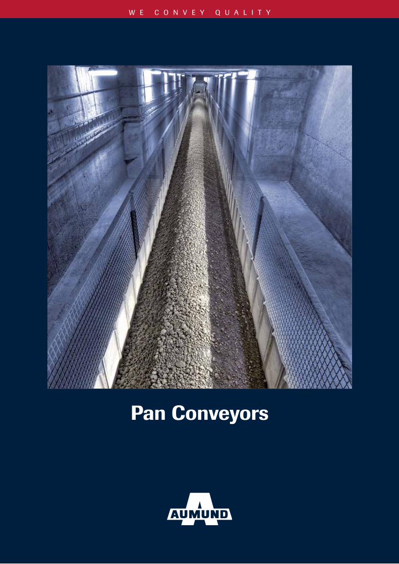
WE CONVEY QUALITY Pan Conveyors
Transcript of Pan Conveyors - AUMUND Fö · PDF file2 AUMUND Pan Conveyors 4 Pan Conveyor with Deep...
W E C O N V E Y Q U A L I T Y
Pan Conveyors
2
Technology with proven quality, strength and reliability
AUMUND Pan Conveyors are designed to suit efficiency driven process technologies and to ensure system performance.
At AUMUND we know that trouble-free operation of the conveying equipment is vital for the productivity and profitability of the whole plant. Keeping in mind this objective we are committed to our high quality standards which are reflected in the exceptional service life of the AUMUND Pan Conveyor.
Our focus is to satisfy specific requirements with creative, cost-effective solutions for the transport of the whole range of bulk materials in cement production from limestone, cement and additives to hot and abrasive cement clinker.
With more than 90 years in industrial engineering of conveying equipment we also assist customers worldwide with conceptual layouts and configuration. Our primary goal is to identify and provide the most efficient and economic conveying routes.
• Forthewholerangeofbulkmaterialsincementproduction• Engineeredtosuitplantandoperatorneeds• Highqualitystandards• Outstandingservicelife• Efficientandeconomicconveyingroutes
Content
2 AUMUND Pan Conveyors
4 Pan Conveyor with Deep Drawn Pans type KZB
8 Pan Conveyor with Deep Drawn Pans and Baffles type KZB-Q
10 Pan Conveyor with Buckets type BZB
14 Pivoting Pan Conveyor type SPB
18 Reversible Deep-Drawn Pan Conveyor type KZB-R
19 Silo Discharge type SAK
20 Components Chain Technology
21 Accessories
22 Conversions and Refurbishments
23 After Sales Services
AUMUNDPan Conveyors
3
4
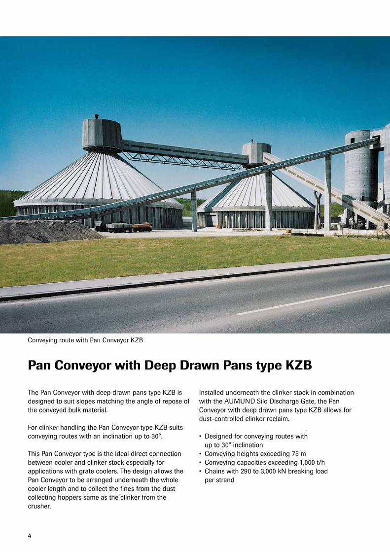
Pan Conveyor with Deep Drawn Pans type KZB
The Pan Conveyor with deep drawn pans type KZB is designed to suit slopes matching the angle of repose of the conveyed bulk material.
ForclinkerhandlingthePanConveyortypeKZBsuitsconveying routes with an inclination up to 30°.
This Pan Conveyor type is the ideal direct connection between cooler and clinker stock especially for applications with grate coolers. The design allows the Pan Conveyor to be arranged underneath the whole cooler length and to collect the fines from the dust collecting hoppers same as the clinker from the crusher.
Installed underneath the clinker stock in combination with the AUMUND Silo Discharge Gate, the Pan Conveyor with deep drawn pans type KZB allows for dust-controlled clinker reclaim.
• Designedforconveyingrouteswith up to 30° inclination• Conveyingheightsexceeding75m• Conveyingcapacitiesexceeding1,000t/h• Chainswith290to3,000kNbreakingload
per strand
Conveying route with Pan Conveyor KZB
5
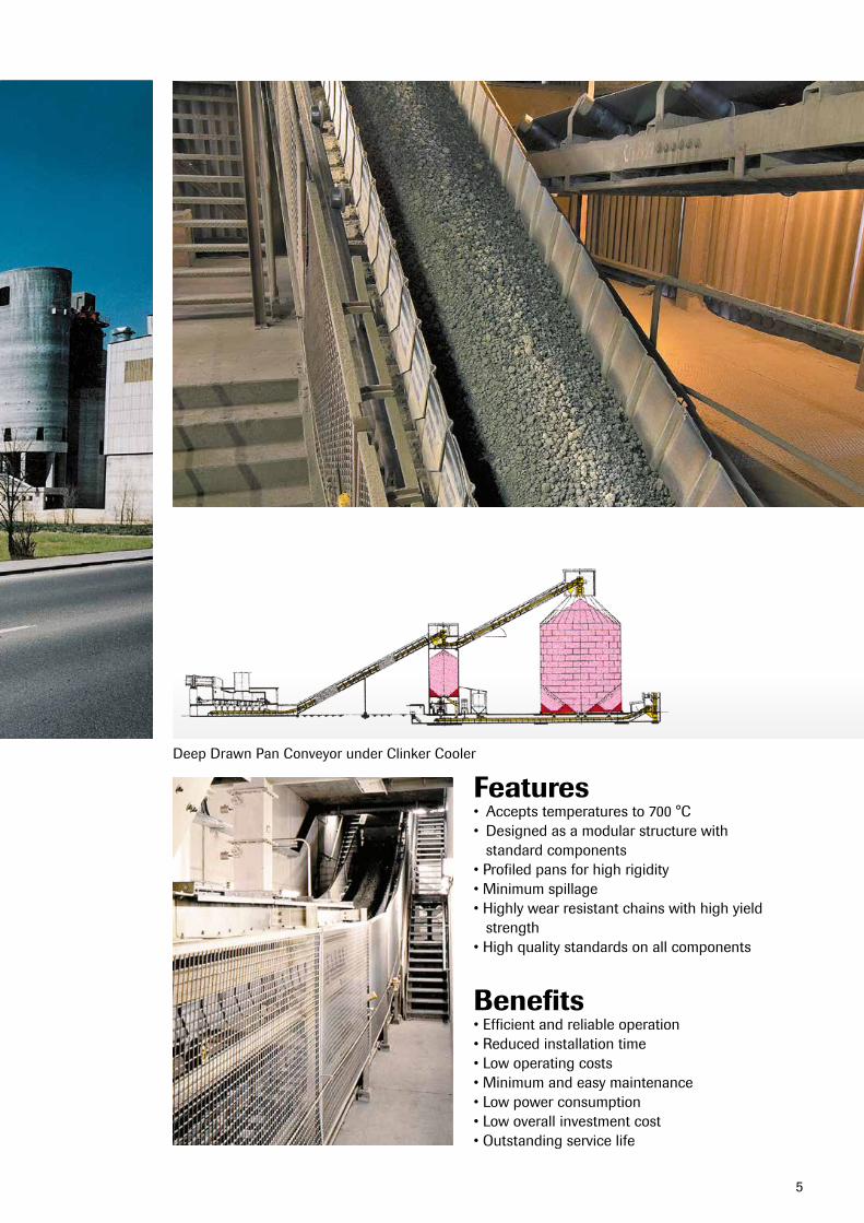
Features• Acceptstemperaturesto700°C• Designedasamodularstructurewith
standard components•Profiledpansforhighrigidity•Minimumspillage•Highlywearresistantchainswithhighyield
strength•Highqualitystandardsonallcomponents
Benefits•Efficientandreliableoperation•Reducedinstallationtime•Lowoperatingcosts•Minimumandeasymaintenance•Lowpowerconsumption•Lowoverallinvestmentcost•Outstandingservicelife
Deep Drawn Pan Conveyor under Clinker Cooler
6
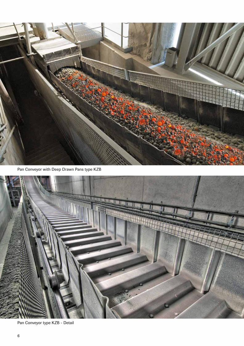
Pan Conveyor with Deep Drawn Pans type KZB
Pan Conveyor type KZB - Detail
7
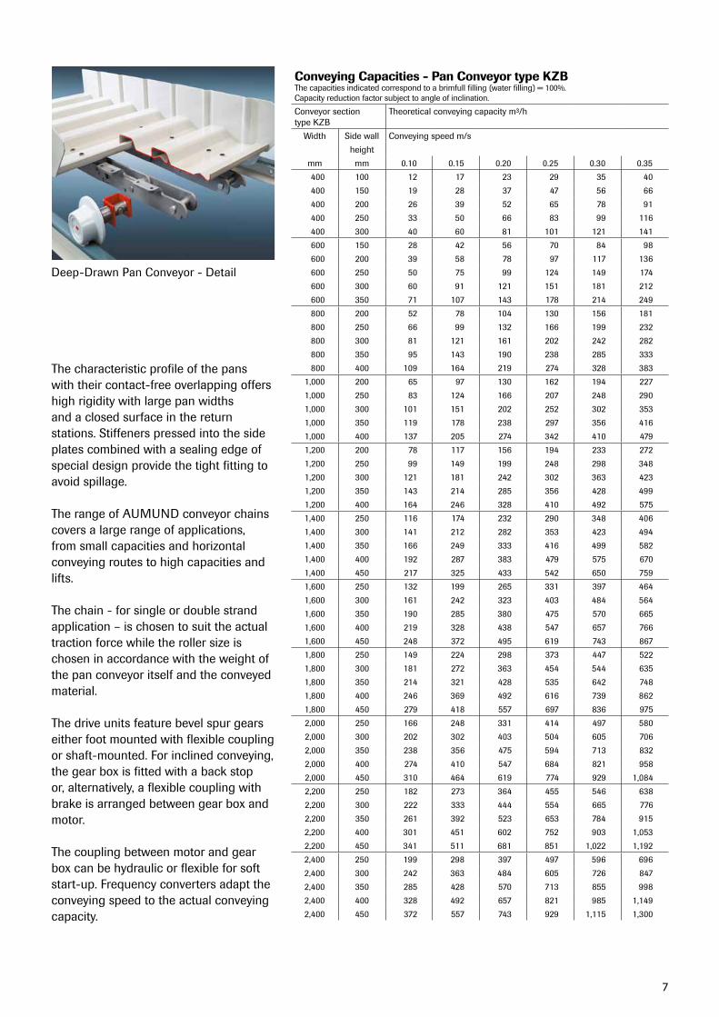
Deep-Drawn Pan Conveyor - Detail
The characteristic profile of the panswith their contact-free overlapping offershigh rigidity with large pan widthsand a closed surface in the returnstations. Stiffeners pressed into the sideplates combined with a sealing edge ofspecial design provide the tight fitting toavoid spillage.
The range of AUMUND conveyor chainscovers a large range of applications,from small capacities and horizontalconveying routes to high capacities andlifts.
The chain - for single or double strandapplication – is chosen to suit the actualtraction force while the roller size is chosen in accordance with the weight of the pan conveyor itself and the conveyedmaterial.
The drive units feature bevel spur gearseither foot mounted with flexible couplingorshaft-mounted.Forinclinedconveying,the gear box is fitted with a back stop or, alternatively, a flexible coupling with brake is arranged between gear box and motor.
The coupling between motor and gearbox can be hydraulic or flexible for softstart-up.Frequencyconvertersadapttheconveying speed to the actual conveyingcapacity.
Conveying Capacities - Pan Conveyor type KZBThe capacities indicated correspond to a brimfull filling (water filling) = 100%.Capacity reduction factor subject to angle of inclination.
Conveyor sectiontype KZB
Theoreticalconveyingcapacitym³/h
Width Side wall Conveyingspeedm/s
height
mm mm 0.10 0.15 0.20 0.25 0.30 0.35
400 100 12 17 23 29 35 40
400 150 19 28 37 47 56 66
400 200 26 39 52 65 78 91
400 250 33 50 66 83 99 116
400 300 40 60 81 101 121 141
600 150 28 42 56 70 84 98
600 200 39 58 78 97 117 136
600 250 50 75 99 124 149 174
600 300 60 91 121 151 181 212
600 350 71 107 143 178 214 249
800 200 52 78 104 130 156 181
800 250 66 99 132 166 199 232
800 300 81 121 161 202 242 282
800 350 95 143 190 238 285 333
800 400 109 164 219 274 328 383
1,000 200 65 97 130 162 194 227
1,000 250 83 124 166 207 248 290
1,000 300 101 151 202 252 302 353
1,000 350 119 178 238 297 356 416
1,000 400 137 205 274 342 410 479
1,200 200 78 117 156 194 233 272
1,200 250 99 149 199 248 298 348
1,200 300 121 181 242 302 363 423
1,200 350 143 214 285 356 428 499
1,200 400 164 246 328 410 492 575
1,400 250 116 174 232 290 348 406
1,400 300 141 212 282 353 423 494
1,400 350 166 249 333 416 499 582
1,400 400 192 287 383 479 575 670
1,400 450 217 325 433 542 650 759
1,600 250 132 199 265 331 397 464
1,600 300 161 242 323 403 484 564
1,600 350 190 285 380 475 570 665
1,600 400 219 328 438 547 657 766
1,600 450 248 372 495 619 743 867
1,800 250 149 224 298 373 447 522
1,800 300 181 272 363 454 544 635
1,800 350 214 321 428 535 642 748
1,800 400 246 369 492 616 739 862
1,800 450 279 418 557 697 836 975
2,000 250 166 248 331 414 497 580
2,000 300 202 302 403 504 605 706
2,000 350 238 356 475 594 713 832
2,000 400 274 410 547 684 821 958
2,000 450 310 464 619 774 929 1,084
2,200 250 182 273 364 455 546 638
2,200 300 222 333 444 554 665 776
2,200 350 261 392 523 653 784 915
2,200 400 301 451 602 752 903 1,053
2,200 450 341 511 681 851 1,022 1,192
2,400 250 199 298 397 497 596 696
2,400 300 242 363 484 605 726 847
2,400 350 285 428 570 713 855 998
2,400 400 328 492 657 821 985 1,149
2,400 450 372 557 743 929 1,115 1,300
8
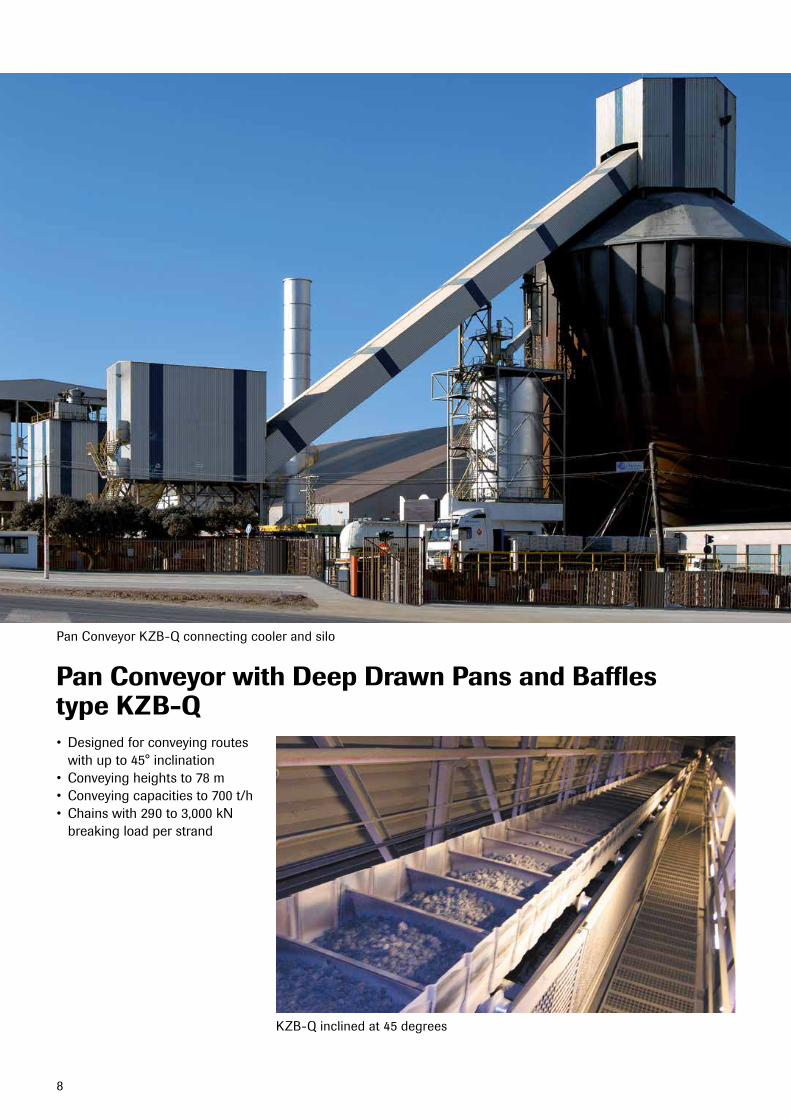
Pan Conveyor with Deep Drawn Pans and Bafflestype KZB-Q
Pan Conveyor KZB-Q connecting cooler and silo
KZB-Qinclinedat45degrees
• Designedforconveyingroutes withupto45°inclination• Conveyingheightsto78m• Conveyingcapacitiesto700t/h• Chainswith290to3,000kN
breaking load per strand
9
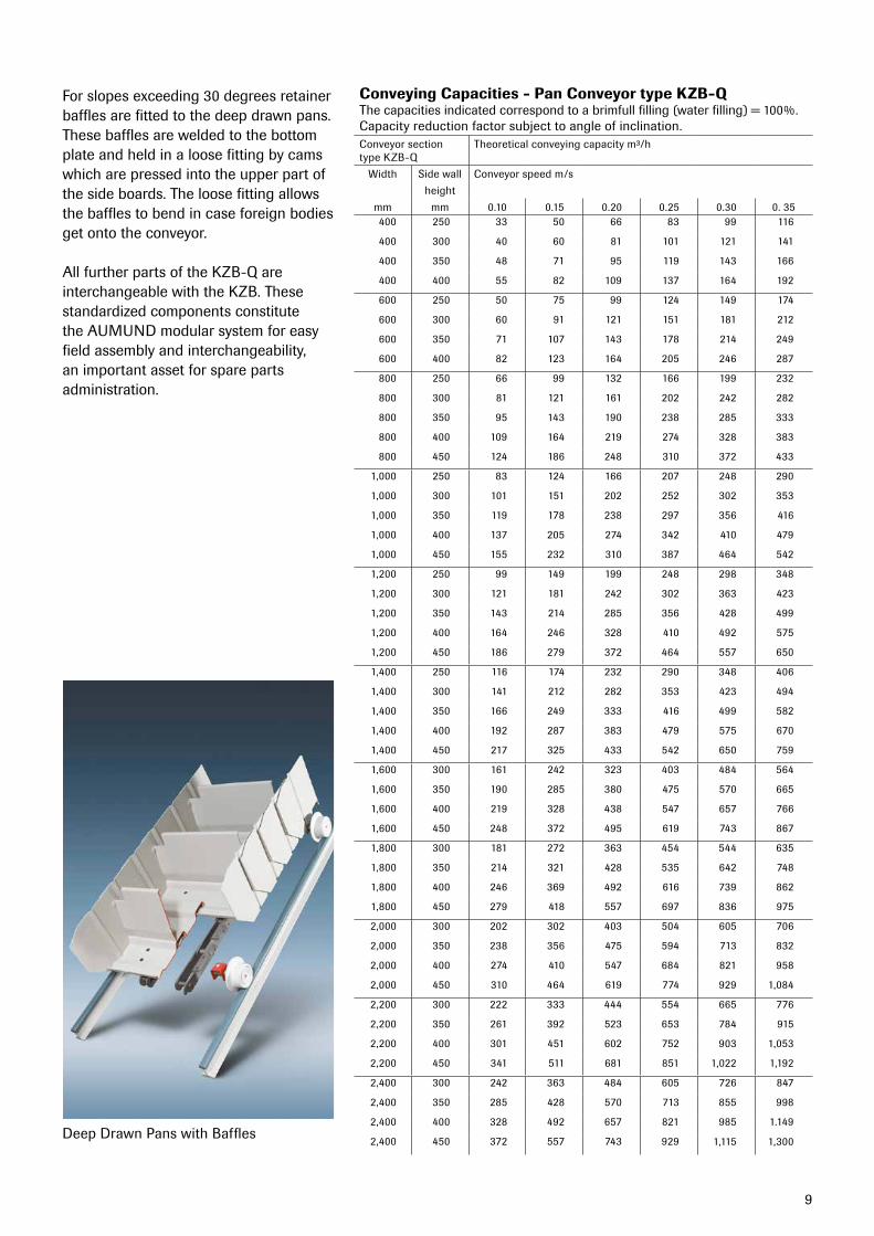
Deep Drawn Pans with Baffles
Forslopesexceeding30degreesretainerbaffles are fitted to the deep drawn pans. These baffles are welded to the bottom plate and held in a loose fitting by cams which are pressed into the upper part of the side boards. The loose fitting allows the baffles to bend in case foreign bodies get onto the conveyor.
All further parts of the KZB-Q are interchangeable with the KZB. These standardized components constitute the AUMUND modular system for easy field assembly and interchangeability, an important asset for spare parts administration.
Conveying Capacities - Pan Conveyor type KZB-QThe capacities indicated correspond to a brimfull filling (water filling) = 100%.Capacity reduction factor subject to angle of inclination.Conveyor sectiontype KZB-Q
Theoreticalconveyingcapacitym³/h
Width Side wall Conveyorspeedm/s
height
mm mm 0.10 0.15 0.20 0.25 0.30 0.35 400 250 33 50 66 83 99 116
400 300 40 60 81 101 121 141
400 350 48 71 95 119 143 166
400 400 55 82 109 137 164 192
600 250 50 75 99 124 149 174
600 300 60 91 121 151 181 212
600 350 71 107 143 178 214 249
600 400 82 123 164 205 246 287
800 250 66 99 132 166 199 232
800 300 81 121 161 202 242 282
800 350 95 143 190 238 285 333
800 400 109 164 219 274 328 383
800 450 124 186 248 310 372 433
1,000 250 83 124 166 207 248 290
1,000 300 101 151 202 252 302 353
1,000 350 119 178 238 297 356 416
1,000 400 137 205 274 342 410 479
1,000 450 155 232 310 387 464 542
1,200 250 99 149 199 248 298 348
1,200 300 121 181 242 302 363 423
1,200 350 143 214 285 356 428 499
1,200 400 164 246 328 410 492 575
1,200 450 186 279 372 464 557 650
1,400 250 116 174 232 290 348 406
1,400 300 141 212 282 353 423 494
1,400 350 166 249 333 416 499 582
1,400 400 192 287 383 479 575 670
1,400 450 217 325 433 542 650 759
1,600 300 161 242 323 403 484 564
1,600 350 190 285 380 475 570 665
1,600 400 219 328 438 547 657 766
1,600 450 248 372 495 619 743 867
1,800 300 181 272 363 454 544 635
1,800 350 214 321 428 535 642 748
1,800 400 246 369 492 616 739 862
1,800 450 279 418 557 697 836 975
2,000 300 202 302 403 504 605 706
2,000 350 238 356 475 594 713 832
2,000 400 274 410 547 684 821 958
2,000 450 310 464 619 774 929 1,084
2,200 300 222 333 444 554 665 776
2,200 350 261 392 523 653 784 915
2,200 400 301 451 602 752 903 1,053
2,200 450 341 511 681 851 1,022 1,192
2,400 300 242 363 484 605 726 847
2,400 350 285 428 570 713 855 998
2,400 400 328 492 657 821 985 1.149
2,400 450 372 557 743 929 1,115 1,300
10
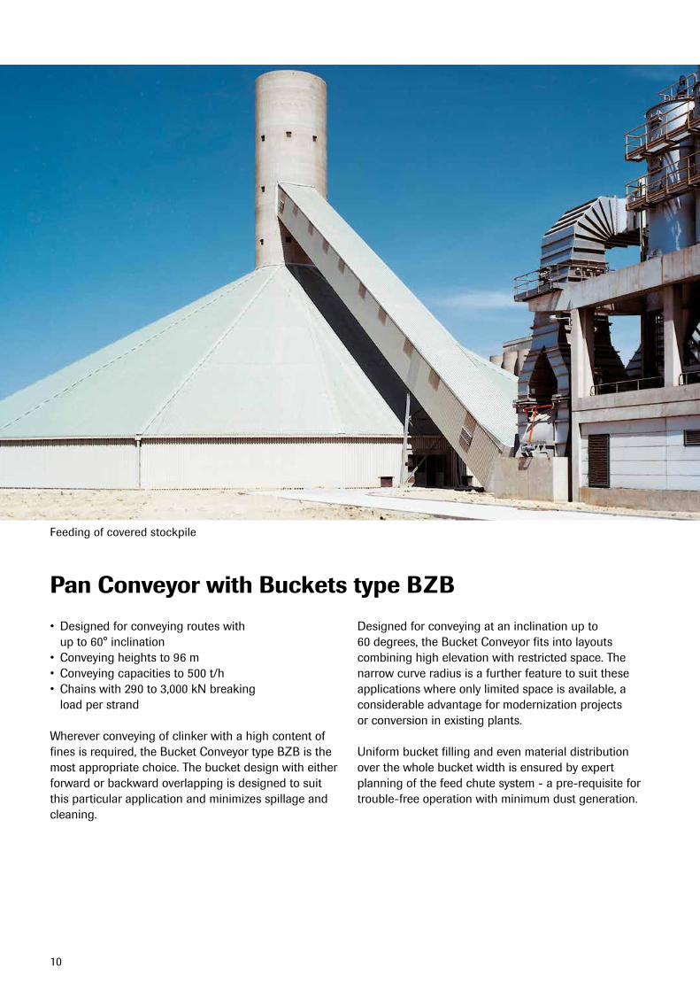
Pan Conveyor with Buckets type BZB
Feedingofcoveredstockpile
• Designedforconveyingrouteswith up to 60° inclination• Conveyingheightsto96m• Conveyingcapacitiesto500t/h• Chainswith290to3,000kNbreaking
load per strand
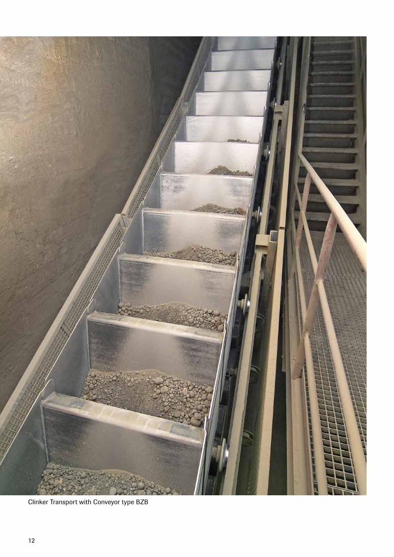
Wherever conveying of clinker with a high content of fines is required, the Bucket Conveyor type BZB is the most appropriate choice. The bucket design with either forward or backward overlapping is designed to suit this particular application and minimizes spillage and cleaning.
Designed for conveying at an inclination up to 60 degrees, the Bucket Conveyor fits into layouts combining high elevation with restricted space. The narrow curve radius is a further feature to suit these applications where only limited space is available, a considerable advantage for modernization projects or conversion in existing plants.
Uniform bucket filling and even material distribution over the whole bucket width is ensured by expert planning of the feed chute system - a pre-requisite for trouble-free operation with minimum dust generation.
11
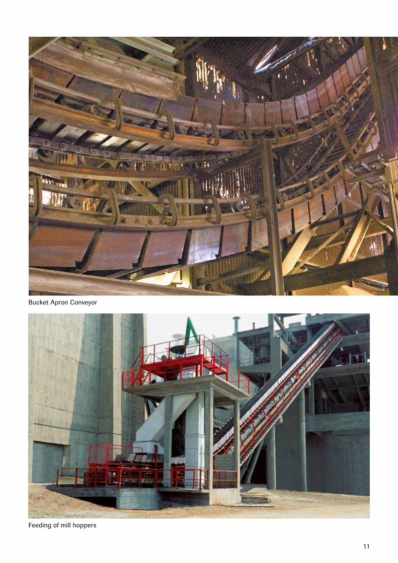
Bucket Apron Conveyor
Feedingofmillhoppers
12
Clinker Transport with Conveyor type BZB
13
Features• Idealforconveyingofclinkerwithahighcontentoffines• Narrowcurveradius,downto10m• Expertdesignofthefeedchutesystem• Designedasamodularstructurewithstandard
components• Minimumspillage• Highlywearresistantchainswithhighyieldstrength• Highqualitystandardsonallcomponents
Benefits• Efficientandreliableoperation• Suitsapplicationswithlimitedspace• Lowoperatingcosts• Minimumandeasymaintenance• Outstandingservicelife
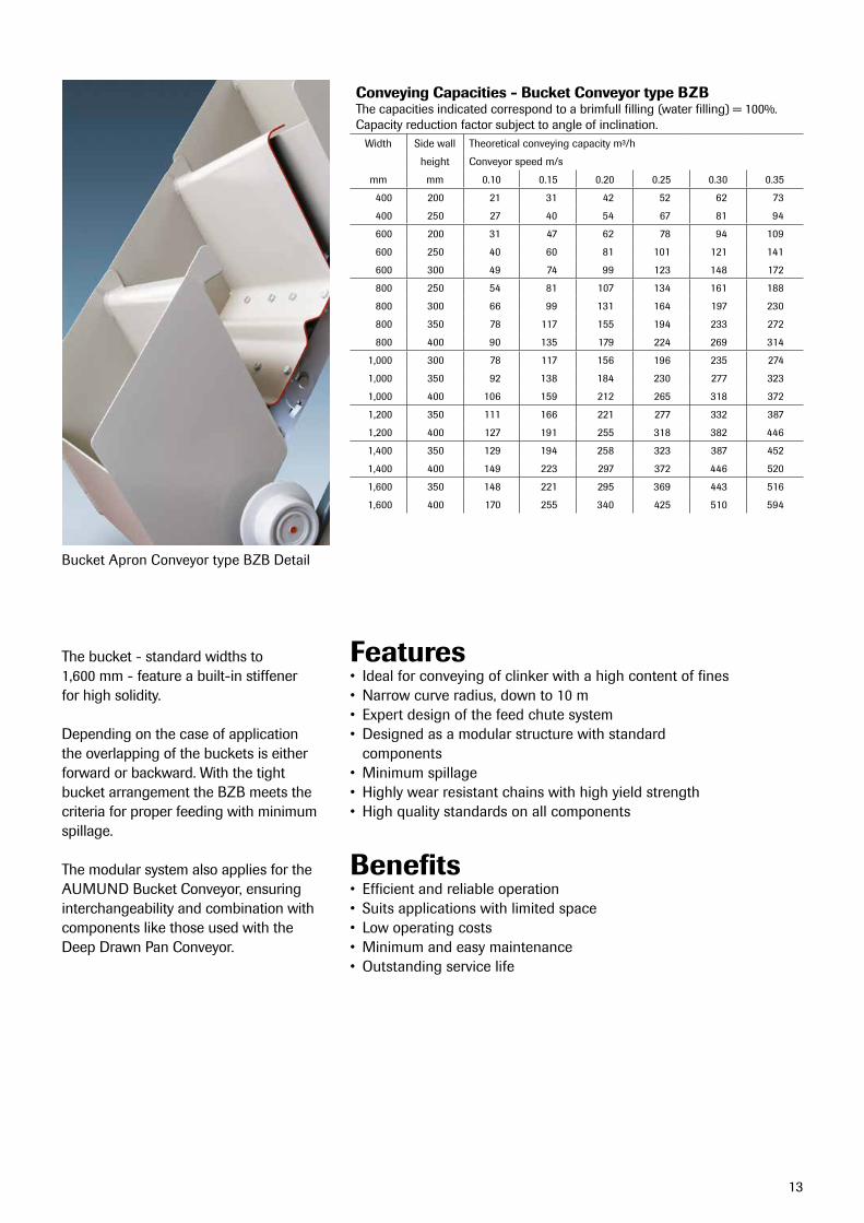
Conveying Capacities - Bucket Conveyor type BZBThe capacities indicated correspond to a brimfull filling (water filling) = 100%.Capacity reduction factor subject to angle of inclination.
Width Side wall Theoreticalconveyingcapacitym³/h
height Conveyorspeedm/s
mm mm 0.10 0.15 0.20 0.25 0.30 0.35
400 200 21 31 42 52 62 73
400 250 27 40 54 67 81 94
600 200 31 47 62 78 94 109
600 250 40 60 81 101 121 141
600 300 49 74 99 123 148 172
800 250 54 81 107 134 161 188
800 300 66 99 131 164 197 230
800 350 78 117 155 194 233 272
800 400 90 135 179 224 269 314
1,000 300 78 117 156 196 235 274
1,000 350 92 138 184 230 277 323
1,000 400 106 159 212 265 318 372
1,200 350 111 166 221 277 332 387
1,200 400 127 191 255 318 382 446
1,400 350 129 194 258 323 387 452
1,400 400 149 223 297 372 446 520
1,600 350 148 221 295 369 443 516
1,600 400 170 255 340 425 510 594
Bucket Apron Conveyor type BZB Detail
The bucket - standard widths to 1,600 mm - feature a built-in stiffener for high solidity.
Depending on the case of application the overlapping of the buckets is either forward or backward. With the tight bucket arrangement the BZB meets the criteria for proper feeding with minimum spillage.
The modular system also applies for the AUMUND Bucket Conveyor, ensuring interchangeability and combination with components like those used with the Deep Drawn Pan Conveyor.
14
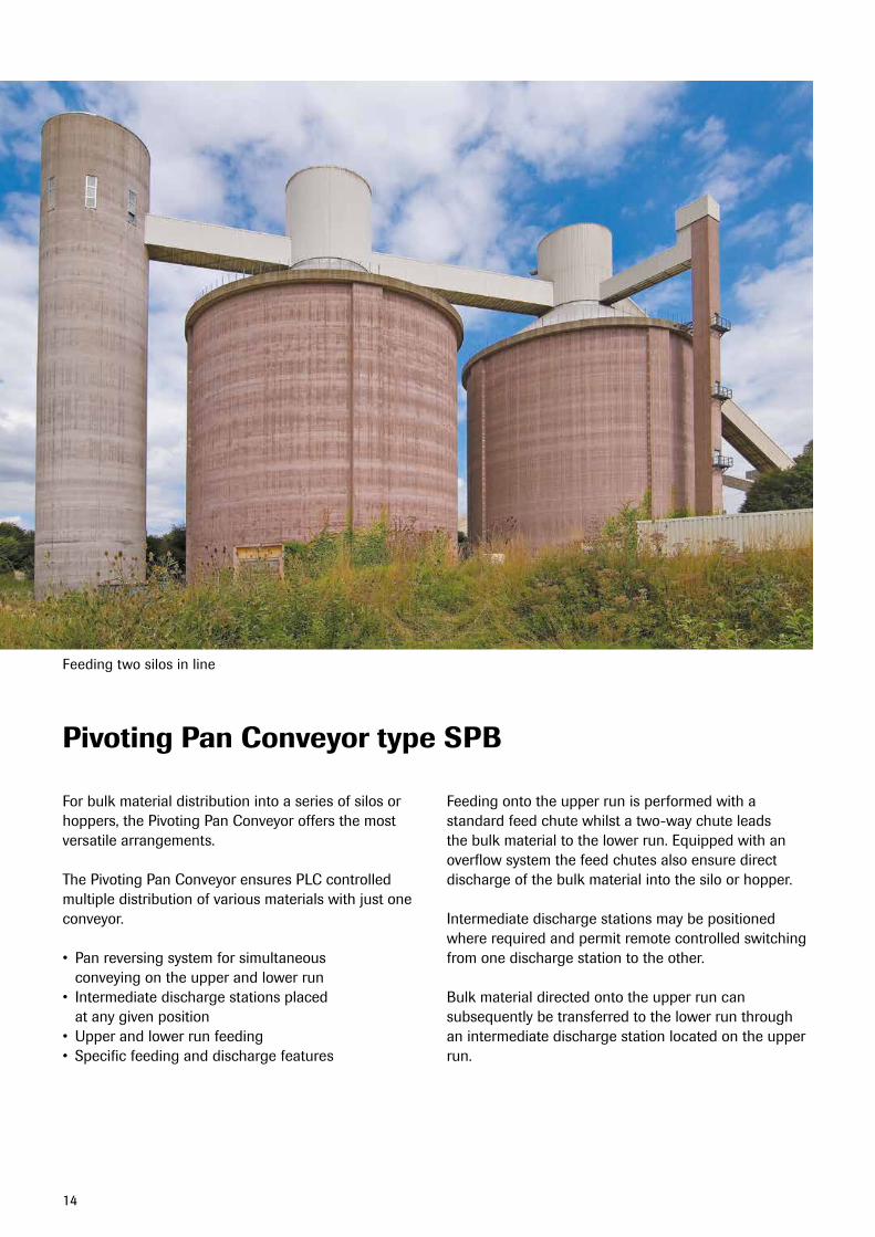
Pivoting Pan Conveyor type SPB
Forbulkmaterialdistributionintoaseriesofsilosorhoppers, the Pivoting Pan Conveyor offers the most versatile arrangements.
The Pivoting Pan Conveyor ensures PLC controlled multiple distribution of various materials with just one conveyor.
• Panreversingsystemforsimultaneous conveying on the upper and lower run• Intermediatedischargestationsplaced
at any given position• Upperandlowerrunfeeding• Specificfeedinganddischargefeatures
Feedingontotheupperrunisperformedwithastandard feed chute whilst a two-way chute leads the bulk material to the lower run. Equipped with an overflow system the feed chutes also ensure direct discharge of the bulk material into the silo or hopper.
Intermediate discharge stations may be positioned where required and permit remote controlled switching from one discharge station to the other.
Bulk material directed onto the upper run can subsequently be transferred to the lower run through an intermediate discharge station located on the upper run.
Feedingtwosilosinline
15
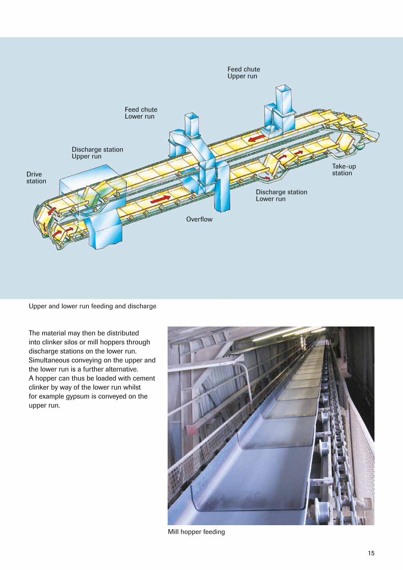
The material may then be distributed into clinker silos or mill hoppers through discharge stations on the lower run. Simultaneous conveying on the upper and the lower run is a further alternative. A hopper can thus be loaded with cement clinker by way of the lower run whilst for example gypsum is conveyed on the upper run.
Upper and lower run feeding and discharge
FeedchuteUpper run
FeedchuteLower run
Discharge stationUpper run
Overflow
Discharge stationLower run
Take-upstationDrive
station
Mill hopper feeding
16
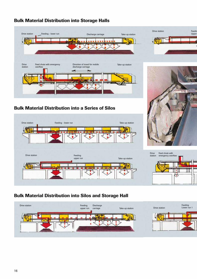
Possible applications - Pivoting Pan Conveyor type SPB
Drive station Feeding - lower run Take-up station
Drive stationTake-up station
FeedingUpper run
Feeding Lower run 2
Feeding Lower run 1
Feeding Upper runDischarge carriage
Discharge carriage
Discharge carriage
Feed chute with emergency overflow
Direction of travel for mobiledischarge carriage
Drive station Take-up station
Drive station
Take-up station
Possible applications - Pivoting Pan Conveyor type SPB
Drive station Feeding - lower run Take-up station
Drive stationTake-up station
Feedingupper run
Feedingupper run
Dischargecarriage
Feed chute withemergency overflow Discharge station
Drive stationTake-up station
Drive station
Take-up stationwith forced discharge
Possible applications - Pivoting Pan Conveyor type SPB
Drive station Feeding - lower run Take-up station
Drive stationTake-up station
FeedingUpper run
Feeding Lower run 2
Feeding Lower run 1
Feeding Upper runDischarge carriage
Discharge carriage
Discharge carriage
Feed chute with emergency overflow
Direction of travel for mobiledischarge carriage
Drive station Take-up station
Drive station
Take-up station
Possible applications - Pivoting Pan Conveyor type SPB
Drive station Feeding - lower run Take-up station
Drive stationTake-up station
Feedingupper run
Feedingupper run
Dischargecarriage
Feed chute withemergency overflow Discharge station
Drive stationTake-up station
Drive station
Take-up stationwith forced discharge
Bulk Material Distribution into Storage Halls
Bulk Material Distribution into a Series of Silos
Bulk Material Distribution into Silos and Storage Hall
17Possible applications - Pivoting Pan Conveyor type SPB
Drive station Feeding - lower run Take-up station
Drive stationTake-up station
FeedingUpper run
Feeding Lower run 2
Feeding Lower run 1
Feeding Upper runDischarge carriage
Discharge carriage
Discharge carriage
Feed chute with emergency overflow
Direction of travel for mobiledischarge carriage
Drive station Take-up station
Drive station
Take-up station
Possible applications - Pivoting Pan Conveyor type SPB
Drive station Feeding - lower run Take-up station
Drive stationTake-up station
Feedingupper run
Feedingupper run
Dischargecarriage
Feed chute withemergency overflow Discharge station
Drive stationTake-up station
Drive station
Take-up stationwith forced discharge
Possible applications - Pivoting Pan Conveyor type SPB
Drive station Feeding - lower run Take-up station
Drive stationTake-up station
FeedingUpper run
Feeding Lower run 2
Feeding Lower run 1
Feeding Upper runDischarge carriage
Discharge carriage
Discharge carriage
Feed chute with emergency overflow
Direction of travel for mobiledischarge carriage
Drive station Take-up station
Drive station
Take-up station
Possible applications - Pivoting Pan Conveyor type SPB
Drive station Feeding - lower run Take-up station
Drive stationTake-up station
Feedingupper run
Feedingupper run
Dischargecarriage
Feed chute withemergency overflow Discharge station
Drive stationTake-up station
Drive station
Take-up stationwith forced discharge
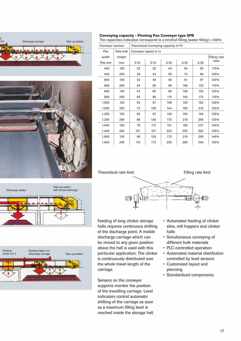
Conveying capacity - Pivoting Pan Conveyor type SPBThe capacities indicated correspond to a brimfull filling (water filling) =100%
Conveyor section Theoretical conveying capacity m3/h
Pan Side wall Conveyorspeedm/s
width height FillingratelimitPlw mm mm 0.10 0.15 0.20 0.25 0.30
400 150 22 32 43 54 65 115%
400 200 29 43 58 72 86 105%
600 150 32 49 65 81 97 120%
600 200 43 65 86 108 130 110%
800 150 43 65 86 108 130 125%
800 200 58 86 115 144 173 115%
1,000 150 54 81 108 135 162 130%
1,000 200 72 108 144 180 216 120%
1,200 150 65 97 130 162 194 135%
1,200 200 86 130 173 216 259 125%
1,400 150 76 113 151 189 227 140%
1,400 200 101 151 202 252 302 130%
1,600 150 86 130 173 216 259 140%
1,600 200 115 173 230 288 346 130%
FillingratelimitTheoretical rate limit
Feedingoflongclinkerstoragehalls requires continuous shifting of the discharge point. A mobile discharge carriage which can be moved to any given position above the hall is used with this particular application. The clinker is continuously distributed over the whole travel length of the carriage.
Sensors on the conveyor supports monitor the position of the travelling carriage. Level indicators control automatic shifting of the carriage as soon as a maximum filling level is reached inside the storage hall.
• Automatedfeedingofclinkersilos, mill hoppers and clinker halls• Simultaneousconveyingof
different bulk materials• PLC-controlledoperation• Automatedmaterialdistribution
controlled by level sensors• Customizedlayoutand
planning• Standardizedcomponents
18
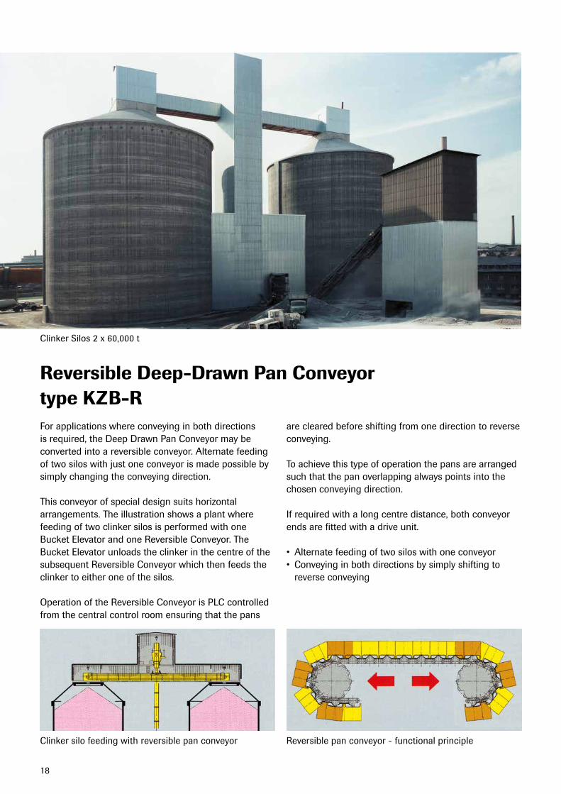
Reversible Deep-Drawn Pan Conveyortype KZB-RForapplicationswhereconveyinginbothdirectionsis required, the Deep Drawn Pan Conveyor may be converted into a reversible conveyor. Alternate feeding of two silos with just one conveyor is made possible by simply changing the conveying direction.
This conveyor of special design suits horizontal arrangements. The illustration shows a plant where feeding of two clinker silos is performed with one Bucket Elevator and one Reversible Conveyor. The Bucket Elevator unloads the clinker in the centre of the subsequent Reversible Conveyor which then feeds the clinker to either one of the silos.
Operation of the Reversible Conveyor is PLC controlled from the central control room ensuring that the pans
are cleared before shifting from one direction to reverse conveying.
To achieve this type of operation the pans are arranged such that the pan overlapping always points into the chosen conveying direction.
If required with a long centre distance, both conveyor ends are fitted with a drive unit.
• Alternatefeedingoftwosiloswithoneconveyor• Conveyinginbothdirectionsbysimplyshiftingto
reverse conveying
Clinker Silos 2 x 60,000 t
Clinker silo feeding with reversible pan conveyor Reversible pan conveyor - functional principle
19
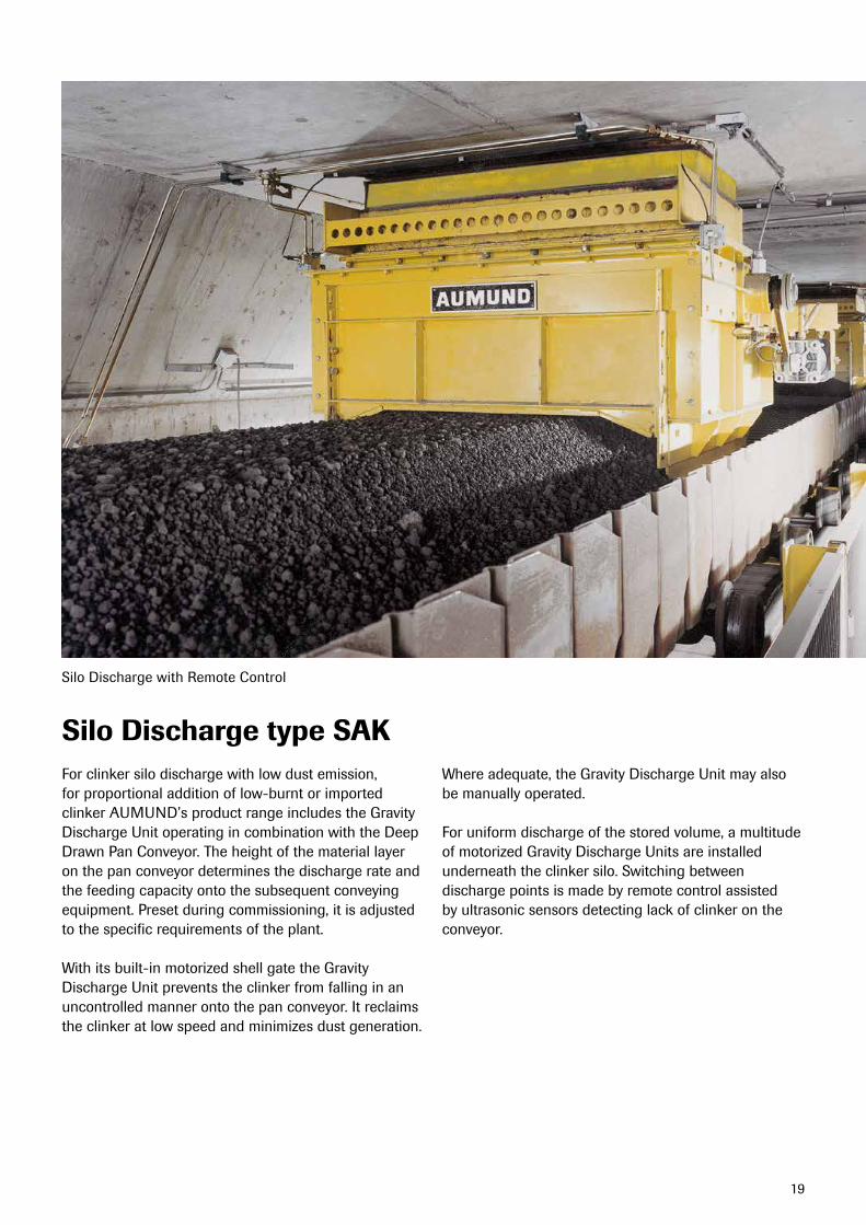
Silo Discharge type SAKForclinkersilodischargewithlowdustemission,for proportional addition of low-burnt or imported clinker AUMUND’s product range includes the Gravity Discharge Unit operating in combination with the Deep Drawn Pan Conveyor. The height of the material layer on the pan conveyor determines the discharge rate and the feeding capacity onto the subsequent conveying equipment. Preset during commissioning, it is adjusted to the specific requirements of the plant.
With its built-in motorized shell gate the Gravity Discharge Unit prevents the clinker from falling in an uncontrolled manner onto the pan conveyor. It reclaims the clinker at low speed and minimizes dust generation.
Where adequate, the Gravity Discharge Unit may also be manually operated.
Foruniformdischargeofthestoredvolume,amultitudeof motorized Gravity Discharge Units are installed underneath the clinker silo. Switching between discharge points is made by remote control assisted by ultrasonic sensors detecting lack of clinker on the conveyor.
Silo Discharge with Remote Control
20
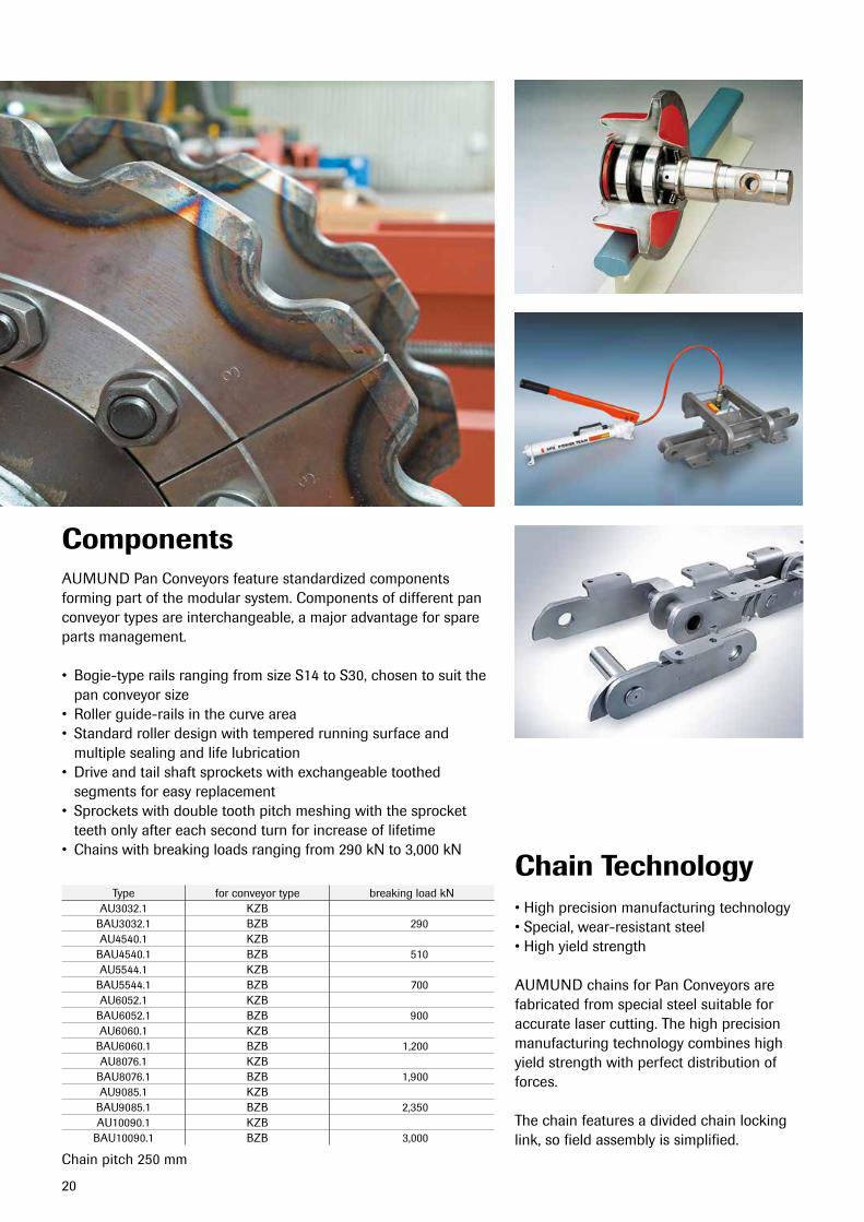
Components
Chain Technology
AUMUND Pan Conveyors feature standardized components forming part of the modular system. Components of different pan conveyor types are interchangeable, a major advantage for spare parts management.
• Bogie-typerailsrangingfromsizeS14toS30,chosentosuitthepan conveyor size• Rollerguide-railsinthecurvearea• Standardrollerdesignwithtemperedrunningsurfaceand
multiple sealing and life lubrication• Driveandtailshaftsprocketswithexchangeabletoothed
segments for easy replacement• Sprocketswithdoubletoothpitchmeshingwiththesprocket
teeth only after each second turn for increase of lifetime• Chainswithbreakingloadsrangingfrom290kNto3,000kN
•Highprecisionmanufacturingtechnology•Special,wear-resistantsteel•Highyieldstrength
AUMUND chains for Pan Conveyors are fabricated from special steel suitable for accurate laser cutting. The high precision manufacturing technology combines high yield strength with perfect distribution of forces.
The chain features a divided chain locking link, so field assembly is simplified.
Type for conveyor type breaking load kNAU3032.1 KZB
BAU3032.1 BZB 290AU4540.1 KZBBAU4540.1 BZB 510AU5544.1 KZBBAU5544.1 BZB 700AU6052.1 KZBBAU6052.1 BZB 900AU6060.1 KZB
BAU6060.1 BZB 1,200AU8076.1 KZBBAU8076.1 BZB 1,900AU9085.1 KZBBAU9085.1 BZB 2,350AU10090.1 KZB
BAU10090.1 BZB 3,000
Chainpitch250mm
21
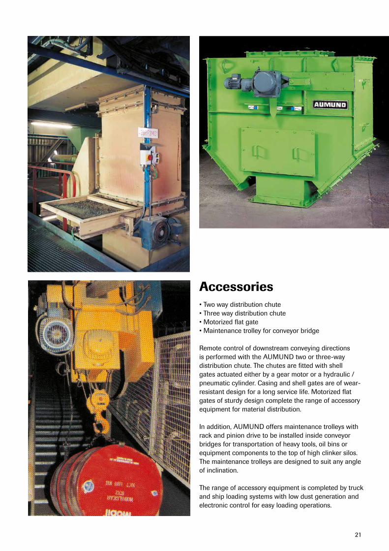
Accessories•Twowaydistributionchute•Threewaydistributionchute•Motorizedflatgate•Maintenancetrolleyforconveyorbridge
Remote control of downstream conveying directions is performed with the AUMUND two or three-way distribution chute. The chutes are fitted with shell gatesactuatedeitherbyagearmotororahydraulic/pneumatic cylinder. Casing and shell gates are of wear-resistant design for a long service life. Motorized flat gates of sturdy design complete the range of accessory equipment for material distribution.
In addition, AUMUND offers maintenance trolleys with rack and pinion drive to be installed inside conveyor bridges for transportation of heavy tools, oil bins or equipment components to the top of high clinker silos. The maintenance trolleys are designed to suit any angle of inclination.
The range of accessory equipment is completed by truck and ship loading systems with low dust generation and electronic control for easy loading operations.
22
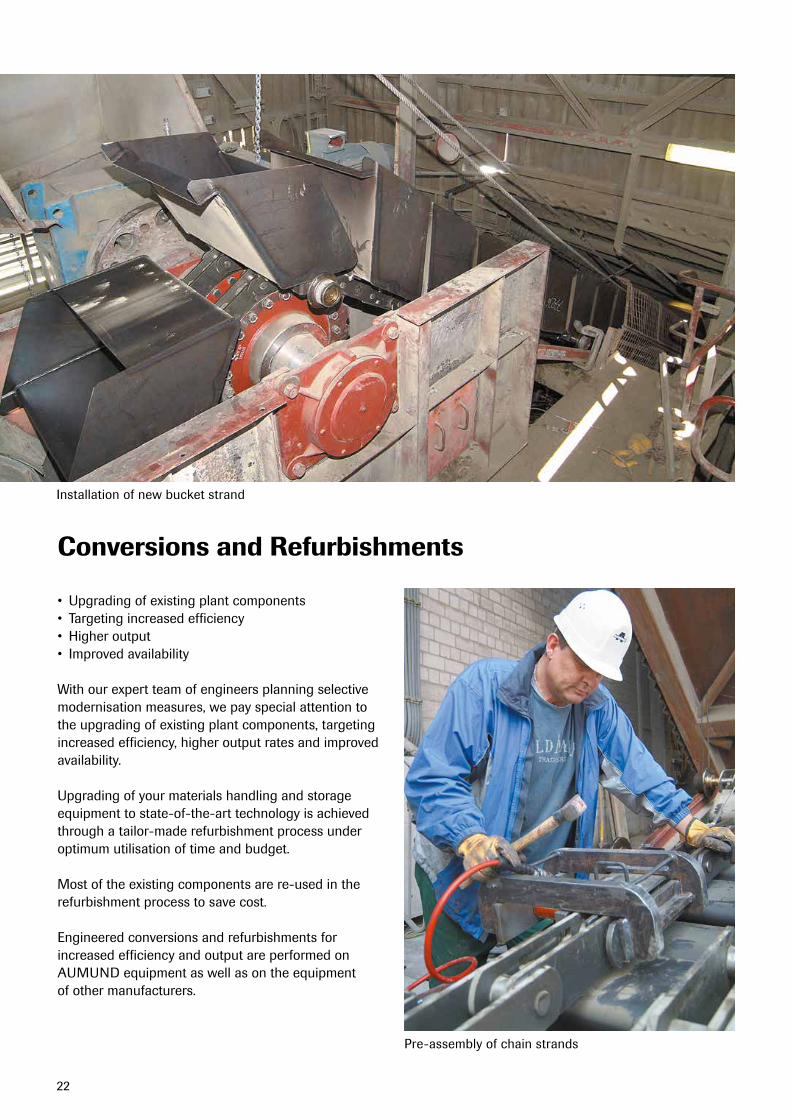
Installation of new bucket strand
Pre-assembly of chain strands
Conversions and Refurbishments
• Upgradingofexistingplantcomponents• Targetingincreasedefficiency• Higheroutput• Improvedavailability
With our expert team of engineers planning selective modernisation measures, we pay special attention to the upgrading of existing plant components, targeting increased efficiency, higher output rates and improved availability.
Upgrading of your materials handling and storage equipment to state-of-the-art technology is achieved through a tailor-made refurbishment process under optimum utilisation of time and budget.
Most of the existing components are re-used in the refurbishment process to save cost.
Engineered conversions and refurbishments for increased efficiency and output are performed on AUMUND equipment as well as on the equipment of other manufacturers.
23
tHe AUMUnD GRoUP
GERMANY
AUMUND Fördertechnik GmbHSaalhofferStr.1747495RheinbergPhone: +49-2843-720Fax: [email protected]
AUMUND Logistic GmbHSaalhofferStr.1747495RheinbergPhone: +49-2843-720Fax: [email protected]
SCHADE Lagertechnik GmbHBruchstraße 145883GelsenkirchenPhone: +49-209-503160Fax: +49-209-50316288sales@schade-lagertechnik.comwww.schade-lagertechnik.com
GREAT BRITAIN
SAMSON Materials Handling Ltd.GeminiHouseCambridgeshireBusiness Park, 1 Bartholomew`s WalkEly,CambridgeshireCB74EAPhone: +44-1353-665001Fax: [email protected]
INDIA
AUMUND Engineering Private Ltd.2ndFloor,LakshmiNeelaRiteChoiceChambers · 9, Bazulla Road, T.NagarChennai-600017Phone: +91 - 44 - 4393 63 00Fax: [email protected]
HONG KONG SAR
AUMUND Asia (H.K.) LimitedUnit3B&5,30/F. 148 Electric Road North Point HongKongPhone: +852-3695-4333Fax: [email protected]
DUBAI U.A.E.
AUMUND Fördertechnik GmbHRepresentative OfficeP.O.Box35291Dubai, UAEPhone: [email protected]
THE NETHERLANDSAUMUND Holding B.V.Wilhelminapark 405911EEVenloPhone: +31-77-3200111Fax: [email protected]
SWITZERLANDAUMUND AGArther Str. 36301 ZugPhone: +41-41-7101082Fax: [email protected]
RUSSIAAUMUND Representative OfficeGerman-RussianHouse,Office44ul.MalajaPirogovskaja5119435Moscow/RussiaPhone: +7-495-2879002Fax: [email protected]
SCHADE Representative OfficeGerman-RussianHouse,Office44ul.MalajaPirogovskaja5119435Moscow/RussiaPhone: +7-495-2879003Fax: [email protected]
FRANCEAUMUND France S.A.R.L.43,ruedeTrévise·F75009ParisPhone: +33-1-42467272Fax: [email protected]
BRAZILAUMUND Ltda.Avenida Eng. Luis Carlos Berrini 716-4.andar-conj.4104571-000-SãoPaulo/SPPhone: +55-11-30590160Fax: [email protected]
USAAUMUND Corporation1701BarrettLakesBlvdBarrett Lakes Center ISuite450Kennesaw, GA 30144Phone: +1-770-226-9578Fax: [email protected]
P.R. CHINAAUMUND Machinery Trading (Beijing) Co. Ltd.Rm.7-8,22-F,EastOceanCentreNo. 24 Jianguomenwai AvenueChaoyang DistrictBeijing 100004Phone: +86-10-65155813/14Fax: [email protected]
After Sales ServiceCustomer Proximity around the WorldAt AUMUND, service does not end at the sale of the equipment. It’s the beginning of a long-term partnership. AUMUND offers you a full range of services – from commissioning to the delivery of quality spare and wear parts to customized preventive maintenance programs and equipment upgrading. The benefits for you: Maximum equipment efficiency at lower operating cost.
Commissioning and Field Service Today, presence “on the spot” is an absolute “must”. Therefore, our commissioning and service engineers operate from support centers on all continents to guarantee immediate and competent support.
Spare and Wear PartsA comprehensive range of genuine spare parts is available for our entire product rangefromstocksinGermany,HongKongand the USA. Our product specialists provide assistance and respond instantly.
Retrofits & ModernisationAged and worn equipment? Capacity increase needed? Too high operating cost? AUMUND “just as new” retrofits are economical and tailor-made solutions for improving your existing equipment at reasonable cost.
Preventive MaintenanceKnowing beforehand that service will be needed allows you to schedule downtime and save money with timely repairs. Repairs or retrofits can be accurately anticipated allowing for the downtime to be at the most convenient times and at the lowest possible cost.
W E C O N V E Y Q U A L I T Y
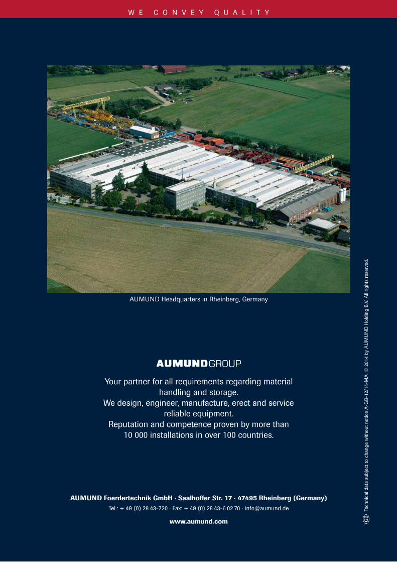
AUMUNDHeadquartersinRheinberg,Germany
Your partner for all requirements regarding material handling and storage.
We design, engineer, manufacture, erect and service reliable equipment.
Reputation and competence proven by more than10 000 installations in over 100 countries.
GBTechnicaldatasubjecttochangewithoutnoticeA-GB-12/14-MA.©2014byAUMUNDHoldingB.V.Allrightsreserved.
AUMUND Foerdertechnik GmbH · Saalhoffer Str. 17 · 47495 Rheinberg (Germany) Tel.:+49(0)28 43-720·Fax:+49(0)28 43-6 02 70·[email protected]
www.aumund.com