
Orthogonal Signals and Modulation Schemes for ...conf-scoop.org/inct-2012/04_hussain_Malek.pdf ·...
6
Orthogonal Signals and Modulation Schemes for Ultrawideband Wireless Communications Malek G. M. Hussain Electrical Engineering Department Kuwait University Khaldyah, Kuwait E-mail:[email protected] Abstract—In this paper, the design of ultrawideband (UWB) orthogonal waveforms that can serve as carrier signals for wireless communications is described. The mathematical models of the UWB orthogonal waveforms are derived in terms of the hyperbolic cosine function (cosh) and the hyperbolic sine function (sinh). The well known digital modulation schemes that involve M-ary phase-shift keying (PSK) and M-ary frequency-shift key- ing (FSK) are applied to the new carrier waveforms to establish a theory for UWB wireless communications. The linear-frequency modulation scheme is also applied to one of the UWB-carrier waveforms to generate a UWB-throb signal that is equivalent to the “chirp” signal widely used in conventional high-resolution radar. A UWB-carrier signal suffers the minimum atmospheric attenuation caused by rain, fog, or molecular absorptions. It also yields effective propagation through lossy media, greater immunity against interference and jamming, and low probability of intercept by a foe receiver. Index Terms—Ultrawideband signals, orthogonal signals, fre- quency shift keying, phase shift keying, ultrawideband commu- nications, ultrawideband radar. I. I NTRODUCTION The theory and practice of the conventional radio transmis- sion systems, which evolved at the beginning of the 1920s, have been based on the commonly used time-harmonic sinu- soidal functions and their inherent phenomenon of resonance. During the last three decades of the twentieth century, the technology for the generation and emission of sinusoidal electromagnetic waves received tremendous developments that enabled wider utilization and efficient management of the frequency spectrum. Ultrawideband (UWB) technology, which has emerged at the dawn of the 21 st century, involves nonsinu- soidal signals having relative frequency bandwidth close to one [1]-[4], sinusoidal signals with a fractional bandwidth larger than 0.25 [5], and random-noise waveforms [6]. The applica- tions of UWB signals are numerous, and the implementation of the UWB technology is simple and cost effective. UWB- impulse-type signals are inherently spread-spectrum signals that are very attractive for ground-penetrating radar, through- foliage imaging radar, secure-wireless communications, med- ical diagnostics and therapy, homeland security, and possible detection of stealth targets. The time variation of a UWB signal, its autocorrelation function and energy spectral density play a major role in system design and performance analysis. In the case of UWB radar, signal design strongly affects performance in terms of target detection in the presence of additive noise, multiple- target resolution, clutter-rejection capability, signal penetration through lossy media, and target classification and recognition [1]-[8]. For UWB-impulse communication, the choice of the carrier signal greatly affects performance in terms of high data rate, information security and reliability, reduced bit error rate, increased system capacity, and greater electromagnetic compatibility in a dens multi-users’ environment [9]-[12]. Much of the recent research work on UWB systems has been focused on the design of pulse shapes that meet the frequency emission regulations (or emission mask) set by the Federal Communications Commission (FCC) [13] in the United States of America (USA). In this paper, periodic and orthogonal nonsinusoidal-carrier waveforms are introduced for advancing the theory and prac- tice of UWB communications and UWB radar. The con- ventional analog and digital modulation schemes that have been based on modulating the amplitude, the frequency, or the phase angle of a sinusoidal-carrier are equally applied to the UWB nonsinusoidal-carrier waveforms to demonstrate their potential usage for UWB communications and UWB radar. In Section II, a set of four periodic and orthogonal nonsinusoidal-carrier waveforms are derived by mathematical manipulations of a UWB generalized-Gaussian pulse (GGP) [14]. In Section III, the digital modulation schemes that are known as M-ary phase-shift keying (M-PSK), and M-ary frequency-shift keying (M-FSK) are extended to the UWB nonsinusoidal-carrier waveforms to obtain mathematical mod- els for the corresponding modulated signals. Also, the linear- frequency modulation method which results in the “chirp” signal, widely used in conventional radar [15]-[18], is applied to a nonsinusoidal-carrier waveform to obtain a UWB-throb signal that is very attractive for high-resolution UWB radar [19],[20]. Conclusions are given in Section IV. II. ULTRAWIDEBAND I MPULSE CARRIER SIGNALS The design and modeling of impulse-type signals are es- sential for the development of the principles and applications of UWB impulse technology. In practice, impulse-type sig- nals should satisfy a set of essential criteria: (i) the time- function, or mathematical model, of the signal is causal so that a physically-realizable radiator and a “matched filter” (or correlator receiver) can be implemented; (ii) the signal model
Transcript of Orthogonal Signals and Modulation Schemes for ...conf-scoop.org/inct-2012/04_hussain_Malek.pdf ·...
Orthogonal Signals and Modulation Schemes
for Ultrawideband Wireless Communications
Malek G. M. Hussain
Electrical Engineering Department
Kuwait University
Khaldyah, Kuwait
E-mail:[email protected]
Abstract—In this paper, the design of ultrawideband (UWB)orthogonal waveforms that can serve as carrier signals forwireless communications is described. The mathematical modelsof the UWB orthogonal waveforms are derived in terms of thehyperbolic cosine function (cosh) and the hyperbolic sine function(sinh). The well known digital modulation schemes that involveM-ary phase-shift keying (PSK) and M-ary frequency-shift key-ing (FSK) are applied to the new carrier waveforms to establish atheory for UWB wireless communications. The linear-frequencymodulation scheme is also applied to one of the UWB-carrierwaveforms to generate a UWB-throb signal that is equivalent tothe “chirp” signal widely used in conventional high-resolutionradar. A UWB-carrier signal suffers the minimum atmosphericattenuation caused by rain, fog, or molecular absorptions. Italso yields effective propagation through lossy media, greaterimmunity against interference and jamming, and low probabilityof intercept by a foe receiver.
Index Terms—Ultrawideband signals, orthogonal signals, fre-quency shift keying, phase shift keying, ultrawideband commu-nications, ultrawideband radar.
I. INTRODUCTION
The theory and practice of the conventional radio transmis-
sion systems, which evolved at the beginning of the 1920s,
have been based on the commonly used time-harmonic sinu-
soidal functions and their inherent phenomenon of resonance.
During the last three decades of the twentieth century, the
technology for the generation and emission of sinusoidal
electromagnetic waves received tremendous developments that
enabled wider utilization and efficient management of the
frequency spectrum. Ultrawideband (UWB) technology, which
has emerged at the dawn of the 21st century, involves nonsinu-
soidal signals having relative frequency bandwidth close to one
[1]-[4], sinusoidal signals with a fractional bandwidth larger
than 0.25 [5], and random-noise waveforms [6]. The applica-
tions of UWB signals are numerous, and the implementation
of the UWB technology is simple and cost effective. UWB-
impulse-type signals are inherently spread-spectrum signals
that are very attractive for ground-penetrating radar, through-
foliage imaging radar, secure-wireless communications, med-
ical diagnostics and therapy, homeland security, and possible
detection of stealth targets.
The time variation of a UWB signal, its autocorrelation
function and energy spectral density play a major role in
system design and performance analysis. In the case of UWB
radar, signal design strongly affects performance in terms of
target detection in the presence of additive noise, multiple-
target resolution, clutter-rejection capability, signal penetration
through lossy media, and target classification and recognition
[1]-[8]. For UWB-impulse communication, the choice of the
carrier signal greatly affects performance in terms of high
data rate, information security and reliability, reduced bit error
rate, increased system capacity, and greater electromagnetic
compatibility in a dens multi-users’ environment [9]-[12].
Much of the recent research work on UWB systems has been
focused on the design of pulse shapes that meet the frequency
emission regulations (or emission mask) set by the Federal
Communications Commission (FCC) [13] in the United States
of America (USA).
In this paper, periodic and orthogonal nonsinusoidal-carrier
waveforms are introduced for advancing the theory and prac-
tice of UWB communications and UWB radar. The con-
ventional analog and digital modulation schemes that have
been based on modulating the amplitude, the frequency, or
the phase angle of a sinusoidal-carrier are equally applied
to the UWB nonsinusoidal-carrier waveforms to demonstrate
their potential usage for UWB communications and UWB
radar. In Section II, a set of four periodic and orthogonal
nonsinusoidal-carrier waveforms are derived by mathematical
manipulations of a UWB generalized-Gaussian pulse (GGP)
[14]. In Section III, the digital modulation schemes that are
known as M-ary phase-shift keying (M-PSK), and M-ary
frequency-shift keying (M-FSK) are extended to the UWB
nonsinusoidal-carrier waveforms to obtain mathematical mod-
els for the corresponding modulated signals. Also, the linear-
frequency modulation method which results in the “chirp”
signal, widely used in conventional radar [15]-[18], is applied
to a nonsinusoidal-carrier waveform to obtain a UWB-throb
signal that is very attractive for high-resolution UWB radar
[19],[20]. Conclusions are given in Section IV.
II. ULTRAWIDEBAND IMPULSE CARRIER SIGNALS
The design and modeling of impulse-type signals are es-
sential for the development of the principles and applications
of UWB impulse technology. In practice, impulse-type sig-
nals should satisfy a set of essential criteria: (i) the time-
function, or mathematical model, of the signal is causal so
that a physically-realizable radiator and a “matched filter” (or
correlator receiver) can be implemented; (ii) the signal model

−1 −0.5 0 0.5 1−0.5
0
0.5
1
Normalized Time (t/∆T )
Norm
aliz
edA
mplit
ude
Generalized Gaussian Pulse Ω(t)
α = 0α = 0.5α = 1.5α = 3
(a)
−2 −1.5 −1 −0.5 0 0.5 1 1.5 2−0.6
−0.4
−0.2
0
0.2
0.4
0.6
0.8
1
Normalized Time (t/∆T )
Norm
aliz
edA
mplit
ude
Autocorrelation Function Υ(t)
α = 0α = 0.5α = 1.5α = 3
(b)
0 1 2 3 4 5 60
0.2
0.4
0.6
0.8
1
Normalized Frequency (f/∆f)
Norm
aliz
edEner
gy
Energy Spectrum Ψ(f)
α = 0α = 0.5α = 1.5α = 3
(b)
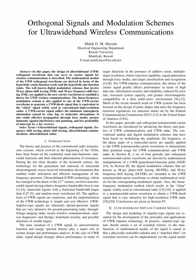
Fig. 1. The generalized Gaussian pulse Ω(t) (a), and its energy spectraldensity Ψ(f) (b), for different values of the scaling factor α.
has useful autocorrelation properties, ideally like a spike with
no time-sidelobes, to achieve a high resolution capability; (iii)
the energy spectral density of the signal is broad and free from
a dc-component to allow for its efficient radiation by a UWB
antenna; (iv) the time function of the signal is mathematically
simple for developing the signal processing theory for the
UWB impulse technology.
Based on experimentation with UWB impulse radiators and
sensors, we have designed a mathematically convenient signal
model, referred to as generalized Gaussian pulse (GGP) [8],
for representing a physically realizable UWB electromagnetic
impulse whose energy spectral density is free from dc com-
ponent. The time variation of the GGP is given by:
Ω(t) = E0
1∑
k=0
Ik exp−ak[(t − t0)/∆T ]2, (1)
where the coefficients Ik and ak are defined as follows,
I0 = 1/(1 − α), a0 = 4π, (2a)
I1 = −I0α, a1 = a0α2. (2b)
In (1), E0 is the peak amplitude at the time t = t0, ∆T is
the effective duration, and α 6= 1 is a scaling parameter that
shapes the energy density spectrum of the GGP signal. The
autocorrelation function Υ(t) of the GGP signal is expressed
as follows,
Υ(t) =
∫ +∞
−∞
Ω(λ)Ω(λ + t) dλ
= E20∆T
2∑
k=0
Ik exp−ak[(t − t0)/∆T ]2,(3)
where the coefficients
I0 = 1/√
8(1 − α)2, a0 = 2π, (4a)
I1 = αI0, a1 = a0α2, (4b)
I2 = −√
8I1/(1 + α2)1/2, a2 = 2a1/(1 + α2). (4c)
The energy spectral density of the signal Ω(t) is given by the
Fourier transform of the autocorrelation function Υ(t), which
yields
Ψ(f) =
(
E0
∆f
)2 2∑
k=0
Ak exp
−σk(f/∆f)2
, (5)
where ∆f = 1/∆T is the effective frequency bandwidth of the
GGP signal, and the coefficients Ak and σk are defined
as follows:
A0 = 1/4(1− α)2, σ0 = π/2, (6a)
A1 = A0, σ1 = σ0/α2, (6b)
A2 = −2A0, σ2 = σ1(1 + α2)/2. (6c)
The time variation of the normalized GGP signal, Ω(t)/E0
, its autocorrelation function Υ(t), and its energy density
spectrum Ψ(f) are plotted in Fig. 1 as a function of relative
time t/∆T , for t0 = 0, and the scaling parameter α = 0
(dotted line), 0.75 (dashed line), 1.5 (dashed-dotted line), and 3
( solid line). For α = 0, the negative time-sidelobes vanish and
Ω(t) becomes an ideal Gaussian pulse as shown in Fig. 1 by
the dotted-line. For α > 0, the energy density spectrum Ψ(f)is free from dc component. Therefore, electromagnetic pulses
with the time variation of the GGP signal can be radiated
without a sinusoidal carrier.
Electromagnetic impulses are inherently of very low energy
content. Consequently, a communication or radar signal must
be composed of a large number of impulses in order to provide
the minimum energy required for detection in the presence of
additive noise. Periodic and orthogonal impulse waveforms
can be generated by pulse-time modulation (PTM), wherein
the pulse parameters are modulated using sinusoidal functions.
Pulse-time modulation of the GGP signal given in (1) by the
sinusoidal functions cosπt/Tr and sin πt/Tr results in two
periodic and orthogonal UWB-impulse waveforms with the
time variations:
Ωc(t) = E0
1∑
k=0
Ik exp
−ak[cos(π(t − t0)/Tr)]2
, (7)
Ωs(t) = E0
1∑
k=0
Ik exp
−ak[sin(π(t − t0)/Tr)]2
. (8)
Using the trigonometric identities (cosx)2 = (1 + cos 2x)/2and (sin x)2 = (1−cos 2x)/2 to simplify the exponents in (7)
and (8), one obtains the waveforms
Ωc(t) = E0
1∑
k=0
qk exp
−ak
2cos(2πt/Tr − θ0)
(9)
Ωs(t) = E0
1∑
k=0
qk exp
+ak
2cos(2πt/Tr − θ0)
, (10)
where the coefficient
qk = Ik exp
−ak
2
, k ∈ [0, 1]. (11)
The parameter Tr is pulse repetition interval (PRI), and the
phase angle θ0 = 2πt0/Tr. For these two periodic impulse
signals, the ratio D = ∆T/Tr is the duty cycle, and fr =1/Tr = D/∆T is the pulse repetition frequency (PRF). The
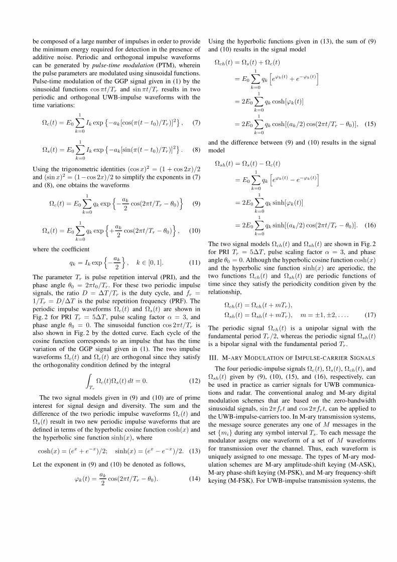
periodic impulse waveforms Ωc(t) and Ωs(t) are shown in
Fig. 2 for PRI Tr = 5∆T , pulse scaling factor α = 3, and
phase angle θ0 = 0. The sinusoidal function cos 2πt/Tr is
also shown in Fig. 2 by the dotted curve. Each cycle of the
cosine function corresponds to an impulse that has the time
variation of the GGP signal given in (1). The two impulse
waveforms Ωc(t) and Ωc(t) are orthogonal since they satisfy
the orthogonality condition defined by the integral∫
Tr
Ωc(t)Ωs(t) dt = 0. (12)
The two signal models given in (9) and (10) are of prime
interest for signal design and diversity. The sum and the
difference of the two periodic impulse waveforms Ωc(t) and
Ωs(t) result in two new periodic impulse waveforms that are
defined in terms of the hyperbolic cosine function cosh(x) and
the hyperbolic sine function sinh(x), where
cosh(x) = (ex + e−x)/2; sinh(x) = (ex − e−x)/2. (13)
Let the exponent in (9) and (10) be denoted as follows,
ϕk(t) =ak
2cos(2πt/Tr − θ0). (14)
Using the hyperbolic functions given in (13), the sum of (9)
and (10) results in the signal model
Ωch(t) = Ωs(t) + Ωc(t)
= E0
1∑
k=0
qk
[
eϕk(t) + e−ϕk(t)]
= 2E0
1∑
k=0
qk cosh[ϕk(t)]
= 2E0
1∑
k=0
qk cosh[(ak/2) cos(2πt/Tr − θ0)], (15)
and the difference between (9) and (10) results in the signal
model
Ωsh(t) = Ωs(t) − Ωc(t)
= E0
1∑
k=0
qk
[
eϕk(t) − e−ϕk(t)]
= 2E0
1∑
k=0
qk sinh[ϕk(t)]
= 2E0
1∑
k=0
qk sinh[(ak/2) cos(2πt/Tr − θ0)]. (16)
The two signal models Ωch(t) and Ωsh(t) are shown in Fig. 2
for PRI Tr = 5∆T , pulse scaling factor α = 3, and phase
angle θ0 = 0. Although the hyperbolic cosine function cosh(x)and the hyperbolic sine function sinh(x) are aperiodic, the
two functions Ωch(t) and Ωsh(t) are periodic functions of
time since they satisfy the periodicity condition given by the
relationship,
Ωch(t) = Ωch(t + mTr),
Ωsh(t) = Ωsh(t + mTr), m = ±1,±2, . . . . (17)
The periodic signal Ωch(t) is a unipolar signal with the
fundamental period Tr/2, whereas the periodic signal Ωsh(t)is a bipolar signal with the fundamental period Tr .
III. M-ARY MODULATION OF IMPULSE-CARRIER SIGNALS
The four periodic-impulse signals Ωc(t), Ωs(t), Ωch(t), and
Ωsh(t) given by (9), (10), (15), and (16), respectively, can
be used in practice as carrier signals for UWB communica-
tions and radar. The conventional analog and M-ary digital
modulation schemes that are based on the zero-bandwidth
sinusoidal signals, sin 2πfrt and cos 2πfrt, can be applied to
the UWB-impulse-carriers too. In M-ary transmission systems,
the message source generates any one of M messages in the
set mi during any symbol interval Ts. To each message the
modulator assigns one waveform of a set of M waveforms
for transmission over the channel. Thus, each waveform is
uniquely assigned to one message. The types of M-ary mod-
ulation schemes are M-ary amplitude-shift keying (M-ASK),
M-ary phase-shift keying (M-PSK), and M-ary frequency-shift
keying (M-FSK). For UWB-impulse transmission systems, the
−15 −10 −5 0 5 10 15−1
−0.5
0
0.5
1
Normalized Time (t/∆T )
Norm
alize
dA
mplitu
de
UWB-Impulse Waveform Ωc(t)
−15 −10 −5 0 5 10 15−1
−0.5
0
0.5
1
Normalized Time (t/∆T )
Norm
alize
dA
mplitu
de
UWB-Impulse Waveform Ωs(t)
−15 −10 −5 0 5 10 15−0.5
0
0.5
1
Normalized Time (t/∆T )
Norm
alize
dA
mplitu
de
UWB-Impulse Waveform Ωch(t)
−15 −10 −5 0 5 10 15−1
−0.5
0
0.5
1
Normalized Time (t/∆T )
Norm
alize
dA
mplitu
de
UWB-Impulse Waveform Ωsh(t)
Fig. 2. The periodic impulse waveforms: Ωc(t), Ωs(t), Ωch(t), and Ωsh(t), with PRI Tr = 5∆T , and pulse scaling factor α = 3. The sinusoidal waveformcos 2πt/Tr is shown by the dotted line.
modulation schemes M-PSK and M-FSK are more practical
and efficient than M-ASK.
A. M-Ary PSK Using UWB-Impulse Carrier
Let the UWB-impulse signal Ωsh(t) given in (16) be used
as a carrier signal for impulse communications. In M-PSK
impulse modulation scheme, the phase of the cosine function
in (14) can take any one of M values in a given symbol
interval Ts, while the amplitude of the impulses is maintained
constant. The symbol duration Ts = NsTr , where the integer
Ns represents the number of impulses per symbol. Using the
periodic impulse waveform Ωsh(t) given in (16) as a carrier
signal, the modulation scheme M-PSK yields the signal set
Ωp(t), 0 ≤ t ≤ Ts defined by
Ωp(t) = E0
1∑
k=0
qk sinh[(ak/2) cos (2πfrt + θi − θ0)], (18)
where the phase angle
θi =(i − 1)2π
M, i = 1, 2, . . . , M. (19)
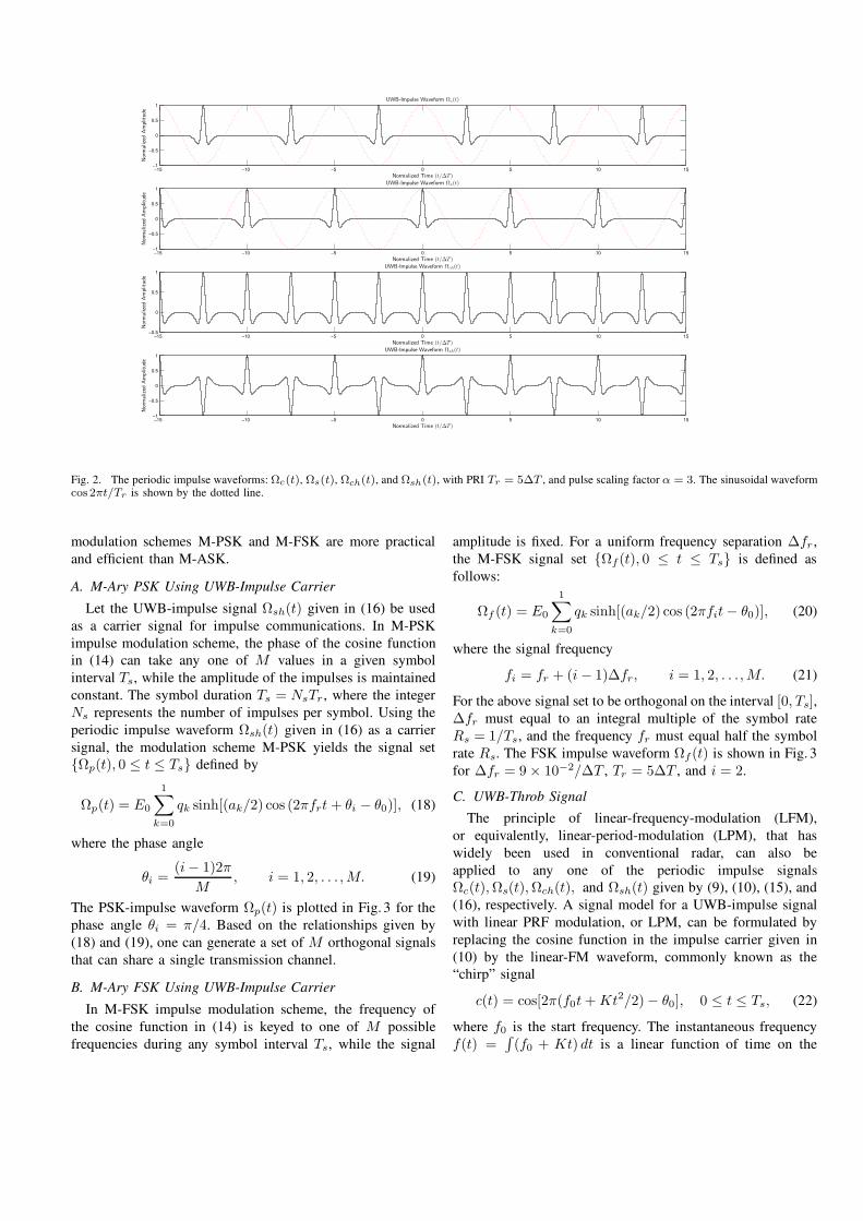
The PSK-impulse waveform Ωp(t) is plotted in Fig. 3 for the
phase angle θi = π/4. Based on the relationships given by
(18) and (19), one can generate a set of M orthogonal signals
that can share a single transmission channel.
B. M-Ary FSK Using UWB-Impulse Carrier
In M-FSK impulse modulation scheme, the frequency of
the cosine function in (14) is keyed to one of M possible
frequencies during any symbol interval Ts, while the signal
amplitude is fixed. For a uniform frequency separation ∆fr ,
the M-FSK signal set Ωf(t), 0 ≤ t ≤ Ts is defined as
follows:
Ωf (t) = E0
1∑
k=0
qk sinh[(ak/2) cos (2πfit − θ0)], (20)
where the signal frequency
fi = fr + (i − 1)∆fr, i = 1, 2, . . . , M. (21)
For the above signal set to be orthogonal on the interval [0, Ts],∆fr must equal to an integral multiple of the symbol rate
Rs = 1/Ts, and the frequency fr must equal half the symbol
rate Rs. The FSK impulse waveform Ωf(t) is shown in Fig. 3
for ∆fr = 9 × 10⁻²/∆T , Tr = 5∆T , and i = 2.
C. UWB-Throb Signal
The principle of linear-frequency-modulation (LFM),
or equivalently, linear-period-modulation (LPM), that has
widely been used in conventional radar, can also be
applied to any one of the periodic impulse signals
Ωc(t), Ωs(t), Ωch(t), and Ωsh(t) given by (9), (10), (15), and
(16), respectively. A signal model for a UWB-impulse signal
with linear PRF modulation, or LPM, can be formulated by
replacing the cosine function in the impulse carrier given in
(10) by the linear-FM waveform, commonly known as the
“chirp” signal
c(t) = cos[2π(f0t + Kt2/2) − θ0], 0 ≤ t ≤ Ts, (22)
where f0 is the start frequency. The instantaneous frequency
f(t) =∫
(f0 + Kt) dt is a linear function of time on the
−15 −10 −5 0 5 10 15−1
−0.5
0
0.5
1
Normalized Time (t/∆T )
Norm
alize
dA
mplitu
de
UWB-Impulse Carrier Waveform Ωsh(t)
−15 −10 −5 0 5 10 15−1
−0.5
0
0.5
1
Normalized Time (t/∆T )
Norm
alize
dA
mplitu
de
PSK-Impulse Waveform Ωp(t)
−15 −10 −5 0 5 10 15−1
−0.5
0
0.5
1
Normalized Time (t/∆T )
Norm
aliz
edA
mplit
ude
FSK-Impulse Waveform Ωf (t)
0 5 10 15−1
−0.5
0
0.5
1
Normalized Time (t/∆T )
Norm
alize
dA
mplitu
de
UWB-Throb Waveform Ωt(t)
Fig. 3. UWB-impulse-carrier signal Ωsh(t), PSK-impulse waveform Ωp(t), FSK-impulse waveform Ωf (t), UWB-throb signal Ωt(t) with PRI Tr = 5∆T ,
throb rate K = 1/5(∆T )2, and pulse scaling factor α = 3. The sinusoidal waveform cos(2πfrt) is shown by the dotted line.
signal interval Ts. The rate at which the frequency changes
with time, (frequency sweep) K (Hz/s), is positive for an “up
chirp” signal and negative for a “down chirp” signal. In (22),
let the start frequency f0 be replaced by the PRF fr = D/∆T ,
the rate of frequency sweep K = nD/(∆T )2, n = 1, 2, 3, . . . ,and the signal duration Ts Tr . With these substitutions, the
insertion of (22) into (1), yields a UWB-impulse signal Ωt(t)with linear-period modulation,
Ωt(t) = E0u(t)
1∑
k=0
qk sinh[−(ak/2) cos[2π(frt + Kt2/2)]]
= E0u(t)
1∑
k=0
qk sinh[−(ak/2)
. cos[2πD(t/∆T ) + nπD(t/∆T )2]], (23)
where u(t) is a rectangular pulse (envelope) of unity amplitude
and duration Ts, and the coefficient qk is defined in (2).
In analogy to the sinusoidal chirp signal c(t) given in (22),
Ωt(t) is referred to as UWB-throb signal. The UWB-throb
signal Ωt(t) and the sinusoidal-chirp signal c(t) are shown
in Fig. 3, for the start frequency f0 = fr = 1/5∆T (Hz)
and frequency sweep K = 1/5(∆T )2 (Hz/s), and scaling
factor α = 3. The inherent large “time-bandwidth product”
of a typical chirp signal used in practice allows for the
simultaneous achievement of improved target detection as well
as high-resolution capabilities for both range and Doppler
(or velocity) [17]. Similarly, a UWB-throb signal that is
composed of a large number of impulses contains the energy
as well as the extremely broad frequency bandwidth required
for improved radar performance in terms of target detection,
resolution, effective penetration depth through lossy media,
and penetration through foliage [19], [20]. The UWB-throb
signal is attractive for ground penetrating radar (GPR), medical
diagnostics and therapy, vehicular radar, and synthetic aperture
radar (SAR) for imaging of targets concealed under foliage.
IV. CONCLUSIONS
The principle of UWB signal design based on time-base
modulation of a generalized Gaussian pulse is presented.
Mathematical time functions for a set of four periodic and
orthogonal UWB-impulse waveforms are derived. The UWB-
impulse waveforms can serve as carrier signals for UWB
impulse communications and impulse radar. The principles
of digital modulation schemes and the linear-frequency mod-
ulation method are applied to a UWB-impulse carrier to
generate M-ary PSK signals, M-ary FSK signals, and a UWB-
throb signal that is attractive for the applications of high-
resolution impulse radar. The mathematical models of the
UWB impulse-carrier signals are simple and convenient for
developing the theory and practice of UWB technology, which
has found numerous commercial, medical, as well as military
applications.
REFERENCES
[1] H. F. Harmuth,Nonsinusoidal Waves for Radar and Radio Communica-
tions.New York: Academic, 1981.[2] M. G. M. Hussain, “Principles of high resolution radar based on non-
sinusoidal waves: Part I. Signal representation and pulse compression,”IEEE Trans. Electromagn. Compat., vol. EMC-31, no. 4, pp. 359-368,
Nov. 1989.

[3] J. D. Taylor, ed., Introduction to Ultra-wideband Radar Systems.Florida:CRC Press, 1995.
[4] Harmuth, H. F., R. N. Boules, and M.G. Hussain, Electromagnetic Sig-
nals: Reflection, Focusing, Distortion, and Their Practical Applications.
Kluwer Academic/Plenum, New York, 1999.
[5] M. Skolnik, G. Andrews, and J. P. Hansen,“Ultra–wideband microwave–radar conceptual design”,IEEE AES Magazine, pp.25–30, October, 1995.
[6] D. C. Bell and R. M. Narayanan, “Theoretical aspects of radar imaging
using stochastic processing”, IEEE Trans. Signal Process. vol. 49, No.2, pp. 394–400, June, 2000
[7] M. G. M. Hussain, “Ultra-wideband impulse radar–An overview of the
principles,” IEEE Aerospace Electronic Systems Magazine, vol. 31, no.9, pp. 9–14, Sept. 1998.
[8] M. G. M. Hussain, “Principles of space-time array processing for
ultrawide-band impulse radar and radio communications,” IEEE Trans.
Veh. Technol., Vol. 51, No. 3, pp. 393–403, May 2002.
[9] M. Z. Win, and R. A. Scholtz, “Impulse radio: How it works,” IEEE
Comm. Letters, vol. 2, no. 2, pp. 36–38, Feb. 1998.[10] M. Z. Win, and R. A. Scholtz, “Ultra-wideband time-hopping spread-
spectrum impulse radio for wireless multiple-access communications ,”Proc. IEEE MILCOM, Boston, MA, Octb. 11-14, 1993.
[11] M. Ghavami, L. B. Michael, and R. Kohno, Ultra Wideband Signals
and Systems in Communication Engineering.Wiley: England, 2004
[12] Bo Hu, and N. C. Beaulieu, “Pulse shapes for ultrawideband com-munication systems,” IEEE Trans. Wireless Comm. vol. 4, no. 4, pp.
1789–1797, July 2005.[13] Revision of Part 15 the Commission’s Rules Regarding Ultra-Wideband
Transmission Systems,FCC, ET Docket 98-153, 2002.
[14] M. G. M. Hussain, “Waveform design and modulation schemes forimpulse communications and radar,” Proc. IEEE Third Intr. Waveform
Diversity and Design Conf., Pisa, Italy, pp. 260–264, June, 2007.
[15] J.R. Klauder, A. C., Price, S. Darlington, and N. J. Albersheim, “Thetheory and design of chirp radar,”Bell Sys. Tech. J., vol. 39, 745, 1960.
[16] J. J. Kroszczynski, “Pulse compression by means of linear period
modulation,” Proc. IEEE, Vol.57, No. 7, pp. 1260–1266, July 1969[17] A.W. Rihaczek, Principles of High Resolution Radar. New York:
McGraw-Hill, 1969.
[18] G. W. Deley, Waveform Design. In “Radar Handbook”, (M. I. Skolnik,ed.). New York: McGraw-Hill, 1970.
[19] M. G. M. Hussain, and M. Khora “Principles of space-time arrayprocessing based on ultrawideband throb signal,” Proc. 2010 IEEE Intr.
Radar Conf., Washington DC, USA, pp. 474–478, May 10-14, 2010.
[20] M. G. M. Hussain, “Ambiguity functions for monostatic and bistaticradar systems using UWB-throb signal”, IEEE Trans. Aerospace and
Electronic Systems, vol. 47, No. 3, pp. 1710–1722, July 2011.
![[2006] Relationship of Modulation Schemes for Matrix Converters.pdf](https://static.fdocuments.in/doc/165x107/577cbfeb1a28aba7118e7b38/2006-relationship-of-modulation-schemes-for-matrix-converterspdf.jpg)


![II Baseband Modulation Schemes 020206[1]](https://static.fdocuments.in/doc/165x107/577d2a511a28ab4e1ea8f601/ii-baseband-modulation-schemes-0202061.jpg)


