Temporal and Spatial Modulation SOLIS VSM...
58
Lecture 10: Polarimeters Outline 1 Temporal and Spatial Modulation 2 Rotating Waveplate Polarimeters 3 HARPS Polarimeter 4 Liquid Crystal Polarimeters 5 SOLIS VSM 6 Piezoacoustic Modulator Polarimeters 7 ZIMPOL 8 Spectral Modulation Polarimeter: SPEX Christoph U. Keller, Utrecht University, [email protected] Astronomical Telescopes and Instruments, Lecture 10: Polarimeters 1
Transcript of Temporal and Spatial Modulation SOLIS VSM...

Lecture 10: Polarimeters
Outline
1 Temporal and Spatial Modulation2 Rotating Waveplate Polarimeters3 HARPS Polarimeter4 Liquid Crystal Polarimeters5 SOLIS VSM6 Piezoacoustic Modulator Polarimeters7 ZIMPOL8 Spectral Modulation Polarimeter: SPEX
Christoph U. Keller, Utrecht University, [email protected] Astronomical Telescopes and Instruments, Lecture 10: Polarimeters 1

Temporal and Spatial Modulation
General Polarimeters
Source Polarization
OpticsCalibrationPolarization
DetectorModulatorSpectro-meterTelescope
polarimeters: optical elements (e.g. retarders, polarizers) thatchange polarization state of incoming light in controlled waydetectors always measure only intensitiesintensity measurements combined to retrieve polarization state ofincoming lightpolarimeters vary by polarization modulation schemepolarimeter should also include polarization calibration optics
Christoph U. Keller, Utrecht University, [email protected] Astronomical Telescopes and Instruments, Lecture 10: Polarimeters 2

Spatial Polarization Modulation
DetectorBeamsplitterPolarizing
polarizing beam-splitter polarimetersimple linear polarimeter: polarizing beam-splitter producing 2beams corresponding to 2 orthogonal linear polarization statesfull linear polarization information from rotating assemblyspatial modulation: simultaneous measurements of two (or more)Stokes parameters
Christoph U. Keller, Utrecht University, [email protected] Astronomical Telescopes and Instruments, Lecture 10: Polarimeters 3

Temporal Polarization Modulation
Detector
rotating waveplate polarimeterrotating retarder, fixed linear polarizermeasured intensity as function of retardance δ, position angle θ
I′ =1
2
„I +
Q
2((1 + cos δ) + (1− cos δ) cos 4θ) +
U
2(1− cos δ) sin 4θ − V sin δ sin 2θ
«
only terms in θ lead to modulated signalequal modulation amplitudes in Q, U, and V for δ=127
temporal modulation: sequential measurements of I± one ormore Stokes parameters
Christoph U. Keller, Utrecht University, [email protected] Astronomical Telescopes and Instruments, Lecture 10: Polarimeters 4

Comparison of Temporal and Spatial Modulation Schemes
Modulation Advantages Disadvantagestemporal negligible effects of flat
field and optical aber-rations
influence of seeing ifmodulation is slow
potentially high polari-metric sensitivity
limited read-out rate ofarray detectors
spatial off-the-shelf array de-tectors
requires up to fourtimes larger sensor
high photon collectionefficiency
influence of flat field
allows post-facto re-construction
influence of differentialaberrations
schemes rather complementary⇒ modern, sensitive polarimeters useboth to combine advantages and minimize disadvantages
Christoph U. Keller, Utrecht University, [email protected] Astronomical Telescopes and Instruments, Lecture 10: Polarimeters 5

Rotating Waveplate Polarimeters
Fundamentals
I′ =1
2
„I +
Q
2((1 + cos δ) + (1− cos δ) cos 4θ) +
U
2(1− cos δ) sin 4θ − V sin δ sin 2θ
«
Q, U modulated at twice the frequency of Vphase shift in modulation between Q and U is 90⇒measurements at 8 angles to determine all 4 Stokes parameters
Christoph U. Keller, Utrecht University, [email protected] Astronomical Telescopes and Instruments, Lecture 10: Polarimeters 6

Double-Ratio Techniquecombination of spatial and temporal modulationdata reduction minimizes effects of many artifactsrotatable quarter-wave plate, polarizing beam-splitterconsider case of circularly polarized lightquarter-wave plate switches between +45 or -45 to polarizingbeam-splitterboth beams recorded simultaneouslyfour measurements are combined to obtain estimate ofStokes V/I ratio largely free of effects from seeing and gainvariations between different detector areasexcellent if polarization signal is smallfrequently used in stellar polarimetrycan be applied to any polarized Stokes parameterworks very well for solar applications where the spectrum in thefirst and the second exposures are different
Christoph U. Keller, Utrecht University, [email protected] Astronomical Telescopes and Instruments, Lecture 10: Polarimeters 7

Double-Ratio Technique (continued)measured intensities in two beams in first exposure
Sl1 = glα1(I1 + V1), Sr
1 = grα1(I1 − V1)
subscript 1: first exposuresubscripts l , r : left, right beamsS: measured signalg: gain in particular beamα: transmission of atmosphere, instrument
second exposure
Sl2 = glα2(I2 − V2), Sr
2 = grα2(I2 + V2)
incoming I and V in second exposure may be completely differentfrom first exposurealso includes beam-wobble induced by rotation of wave plate
Christoph U. Keller, Utrecht University, [email protected] Astronomical Telescopes and Instruments, Lecture 10: Polarimeters 8

Double-Ratio Technique (continued)combination of 4 measured intensities removes effect oftransmission changes and differential gain variations of differentdetector areas
14
(Sl
1
Sl2
Sr2
Sr1− 1
)=
12
I2V1 + I1V2
I1I2 − I2V1 − I1V2 + V1V2
if V I12
(V1
I1+
V2
I2
)obtain average V/I signal of two exposuresno spurious polarization signals are introduced
Christoph U. Keller, Utrecht University, [email protected] Astronomical Telescopes and Instruments, Lecture 10: Polarimeters 9

HARPS Polarimeter
IntroductionHARPS: Most successful exoplanet findermeasure magnetic fields of planet-hosting starsonly publicly accessible high-resolution spectropolarimeter in thesouthern hemisphere
RequirementsUse slider and volume of Iodine cellDo not compromise performance and operations of HARPSFull StokesPolarimetric sensitivity 10−4 for one night on a bright star380-690 nmMinimal instrumental polarizationMinimal (polarized) fringes
Christoph U. Keller, Utrecht University, [email protected] Astronomical Telescopes and Instruments, Lecture 10: Polarimeters 10

Christoph U. Keller, Utrecht University, [email protected] Astronomical Telescopes and Instruments, Lecture 10: Polarimeters 11

Christoph U. Keller, Utrecht University, [email protected] Astronomical Telescopes and Instruments, Lecture 10: Polarimeters 12
Christoph U. Keller, Utrecht University, [email protected] Astronomical Telescopes and Instruments, Lecture 10: Polarimeters 13

Christoph U. Keller, Utrecht University, [email protected] Astronomical Telescopes and Instruments, Lecture 10: Polarimeters 14

Liquid Crystal Polarimeters
Introductionno moving partsnematic liquid crystals
change retardance with applied electric fieldrelatively slow (<50 Hz)electrically tunable for different wavelengths
ferro-electric liquid crystalsflip fast axis orientation with applied electric field (2 states only)fast (<10 kHz)fixed retardation and optimum wavelength
often combinations of variable liquid crystal retarders and fixedretarders
Christoph U. Keller, Utrecht University, [email protected] Astronomical Telescopes and Instruments, Lecture 10: Polarimeters 15

SOLIS Vector-Spectromagnetograph (VSM)
Christoph U. Keller, Utrecht University, [email protected] Astronomical Telescopes and Instruments, Lecture 10: Polarimeters 16

Christoph U. Keller, Utrecht University, [email protected] Astronomical Telescopes and Instruments, Lecture 10: Polarimeters 17
Christoph U. Keller, Utrecht University, [email protected] Astronomical Telescopes and Instruments, Lecture 10: Polarimeters 18

Christoph U. Keller, Utrecht University, [email protected] Astronomical Telescopes and Instruments, Lecture 10: Polarimeters 19

Christoph U. Keller, Utrecht University, [email protected] Astronomical Telescopes and Instruments, Lecture 10: Polarimeters 20

Christoph U. Keller, Utrecht University, [email protected] Astronomical Telescopes and Instruments, Lecture 10: Polarimeters 21

Christoph U. Keller, Utrecht University, [email protected] Astronomical Telescopes and Instruments, Lecture 10: Polarimeters 22
Christoph U. Keller, Utrecht University, [email protected] Astronomical Telescopes and Instruments, Lecture 10: Polarimeters 23

Christoph U. Keller, Utrecht University, [email protected] Astronomical Telescopes and Instruments, Lecture 10: Polarimeters 24

Christoph U. Keller, Utrecht University, [email protected] Astronomical Telescopes and Instruments, Lecture 10: Polarimeters 25

Christoph U. Keller, Utrecht University, [email protected] Astronomical Telescopes and Instruments, Lecture 10: Polarimeters 26

Christoph U. Keller, Utrecht University, [email protected] Astronomical Telescopes and Instruments, Lecture 10: Polarimeters 27

Christoph U. Keller, Utrecht University, [email protected] Astronomical Telescopes and Instruments, Lecture 10: Polarimeters 28

Separation of Polarization Modulation and PolarizerFLC and retarders located behind spectrograph entrance slitpolarizing beamsplitters located in front of camerasspectrograph and associated optics built to minimize instrumentalpolarization between modulators and polarizing beam splittersadvantages of VSM approach: no moving parts for polarizationanalysis, switching of polarization states can occur rapidly, andboth polarization states are detected simultaneously after havingpassed through the same optics
Christoph U. Keller, Utrecht University, [email protected] Astronomical Telescopes and Instruments, Lecture 10: Polarimeters 29

Piezo-Elastic Modulators (PEMs)stress-induced birefringence, also sometimes called piezo-opticalor photo-elastic effectblock of a few cm in side length of common BK7 glass can bestressed enough by hand such as to introduce a quarter-waveretardationstress-induced birefringence is proportional to stress σretardation (in waves)
δ =1λ
Kdσ
K stress optical constantd thickness of variable retarderλ wavelength
construct variable retarder by compressing optical glassrequires considerable mechanical power to modulate
Christoph U. Keller, Utrecht University, [email protected] Astronomical Telescopes and Instruments, Lecture 10: Polarimeters 30

Mechanical Resonancemechanically resonant oscillation reduces power requirement toone over the mechanical Q (103-104 for most glasses)slab of length L excited at fundamental mode⇒ standing acousticwave with wavelength 2L, frequency ω
ω =cs
2L
cs: sound speed in optical material57-mm-long fused silica slab⇒ resonance frequency is 50 kHz.resulting stress, retardance as function of position x and time tstress-induced birefringence δ(x , t) given by
δ(x , t) = A sinωt sin(πxL
)
A amplitude of oscillationx from 0 to L
Christoph U. Keller, Utrecht University, [email protected] Astronomical Telescopes and Instruments, Lecture 10: Polarimeters 31
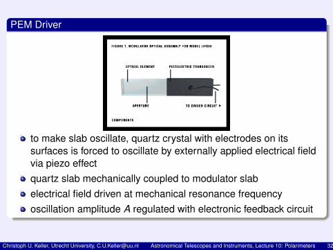
PEM Driver
to make slab oscillate, quartz crystal with electrodes on itssurfaces is forced to oscillate by externally applied electrical fieldvia piezo effectquartz slab mechanically coupled to modulator slabelectrical field driven at mechanical resonance frequencyoscillation amplitude A regulated with electronic feedback circuit
Christoph U. Keller, Utrecht University, [email protected] Astronomical Telescopes and Instruments, Lecture 10: Polarimeters 32

PEM Power
oscillation dampened by friction losses within modulator materialenergy loss inversely proportional to mechanical QQ very large⇒ little energy loss in modulator small (0.1 to 1 W)material with high Q (fused silica, Q ≈ 104) desirabletypical glass has Q ∼ 103
required drive power does not depend on length of slab
Christoph U. Keller, Utrecht University, [email protected] Astronomical Telescopes and Instruments, Lecture 10: Polarimeters 33

PEM Birefringence
stress-induced birefringence
δ(x , t) = A sinωt sin(πxL
)
combine sin(πxL ), amplitude A into spatially varying amplitude A(x)
birefringence becomes δ(x , t) = A(x) sin(ωt)A small⇒ PEM is true zero-order retarderPEM Mueller matrix corresponds to retarder with time-dependentretardationretarder Mueller matrix contains elements with sin δ(x , t) andcos δ(x , t)expand sin(sin(·)) and cos(sin(·)) in terms of Bessel functions
Christoph U. Keller, Utrecht University, [email protected] Astronomical Telescopes and Instruments, Lecture 10: Polarimeters 34

Bessel Functions
Mueller matrix elements become
sin δ(x, t) = 2J1(A(x)) sinωt + · · · ,cos δ(x , t) = J0(A(x)) + 2J2(A(x)) cos 2ωt + · · · ,
J0,1,2: Bessel functions of order 0,1 and 2
Christoph U. Keller, Utrecht University, [email protected] Astronomical Telescopes and Instruments, Lecture 10: Polarimeters 35

PEM Advantages and DisadvantagesAdvantages:
PEMs are stable in operationshow no degrading at high intensity levels and/or UV irradiationhave good optical propertieslarge spatial and angular aperturerequire only low voltages at moderate driving powers (< 1 W)
Disadvantages:sinusoidal modulation (as compared to more efficientsquare-wave modulation possible with liquid crystals)very high modulation frequency (20 to 50 kHz), which requiresspecialized array detectors (ZIMPOL)
Christoph U. Keller, Utrecht University, [email protected] Astronomical Telescopes and Instruments, Lecture 10: Polarimeters 36

Zurich Imaging Polarimeters (ZIMPOL)
CCD Array as Fast Demodulator
Christoph U. Keller, Utrecht University, [email protected] Astronomical Telescopes and Instruments, Lecture 10: Polarimeters 37

Christoph U. Keller, Utrecht University, [email protected] Astronomical Telescopes and Instruments, Lecture 10: Polarimeters 38

CCD Array as Fast DemodulatorZIMPOL I polarization modulator consists of 2 PEMS and apolarizer (single beam)modulation according to
I′(t) =1
2
“I + Q
√2J2(A) cos(2Ω1t) + U
√2J2(A) cos(2Ω2t) + V
√2J1(A) sin(Ω1t)
”
frequencies of PEMs given by Ω1, Ω2
amplitudes of both PEMs, A, chosen such that J0(A) = 0for vector polarimetry: 3 synchronous demodulators, eachsensitive to one of 2Ω1, 2Ω2, Ω1
development of demodulating CCD by Povel and coworkers about20 years agofractional polarization free of flat-field effectsno seeing effects due to high modulation frequency
Christoph U. Keller, Utrecht University, [email protected] Astronomical Telescopes and Instruments, Lecture 10: Polarimeters 39

Christoph U. Keller, Utrecht University, [email protected] Astronomical Telescopes and Instruments, Lecture 10: Polarimeters 40

Christoph U. Keller, Utrecht University, [email protected] Astronomical Telescopes and Instruments, Lecture 10: Polarimeters 41

Christoph U. Keller, Utrecht University, [email protected] Astronomical Telescopes and Instruments, Lecture 10: Polarimeters 42

Christoph U. Keller, Utrecht University, [email protected] Astronomical Telescopes and Instruments, Lecture 10: Polarimeters 43

Christoph U. Keller, Utrecht University, [email protected] Astronomical Telescopes and Instruments, Lecture 10: Polarimeters 44

Christoph U. Keller, Utrecht University, [email protected] Astronomical Telescopes and Instruments, Lecture 10: Polarimeters 45

Christoph U. Keller, Utrecht University, [email protected] Astronomical Telescopes and Instruments, Lecture 10: Polarimeters 46

Christoph U. Keller, Utrecht University, [email protected] Astronomical Telescopes and Instruments, Lecture 10: Polarimeters 47

Christoph U. Keller, Utrecht University, [email protected] Astronomical Telescopes and Instruments, Lecture 10: Polarimeters 48

Christoph U. Keller, Utrecht University, [email protected] Astronomical Telescopes and Instruments, Lecture 10: Polarimeters 49

Christoph U. Keller, Utrecht University, [email protected] Astronomical Telescopes and Instruments, Lecture 10: Polarimeters 50

Christoph U. Keller, Utrecht University, [email protected] Astronomical Telescopes and Instruments, Lecture 10: Polarimeters 51

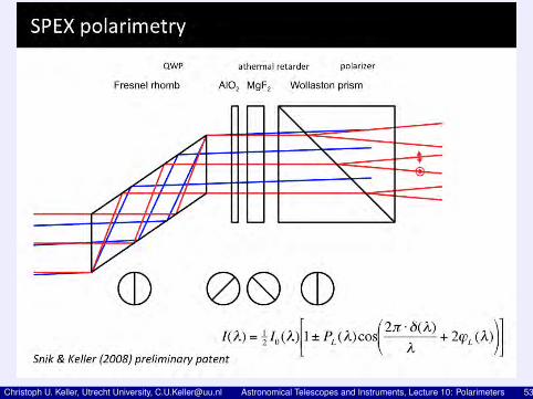
Spectral Modulation
Introduction
optically add modulation to intensity spectrum:modulation amplitude = degree of linear polarization (
√Q2 + U2/i)
modulation phase = orientation of linear polarization (arctanQ/U)Advantages of spectral modulation:
Fully passiveScalableOne-shot measurementNo differential effectsLow susceptibility to noise
Christoph U. Keller, Utrecht University, [email protected] Astronomical Telescopes and Instruments, Lecture 10: Polarimeters 52
Christoph U. Keller, Utrecht University, [email protected] Astronomical Telescopes and Instruments, Lecture 10: Polarimeters 53

SPEX: Spectropolarimeter for Planetary EXplorationMeasure size distribution and composition of planetaryatmospheresdust (storms) on Mars, atmosphere of Jupiter, aerosols in Earthatmosphereneeds to cover large wavelength range,Outlook
Venus-as-an-exoplanet (prototype)Earth from helicopter (prototype)Mars (ExoMars)Jupiter + moons (EJSM)Titan (TandEM)Earth from ISSEarth from microsatellites (FAST)Earth-as-an-exoplanet from the moon (ESA lunar lander)
Christoph U. Keller, Utrecht University, [email protected] Astronomical Telescopes and Instruments, Lecture 10: Polarimeters 54

Christoph U. Keller, Utrecht University, [email protected] Astronomical Telescopes and Instruments, Lecture 10: Polarimeters 55

Christoph U. Keller, Utrecht University, [email protected] Astronomical Telescopes and Instruments, Lecture 10: Polarimeters 56
Christoph U. Keller, Utrecht University, [email protected] Astronomical Telescopes and Instruments, Lecture 10: Polarimeters 57

Christoph U. Keller, Utrecht University, [email protected] Astronomical Telescopes and Instruments, Lecture 10: Polarimeters 58