Original Issue 1 - Interlink Supply Manuals...INDUSTRIAL ENGINE SERVICE MANUAL . Table Of Contents...
183
Original Issue Dated August 2003 Publication Number 36100009 1.6L INDUSTRIAL ENGINE SERVICE MANUAL
Transcript of Original Issue 1 - Interlink Supply Manuals...INDUSTRIAL ENGINE SERVICE MANUAL . Table Of Contents...

Original Issue Dated August 2003
Publication Number 36100009
1.6L INDUSTRIAL ENGINE
SERVICE MANUAL

Table Of Contents
General Information Section 0
Engine Mechanical Section 1
Engine Cooling Section 2
Engine Electrical Section 3
No part of this publication may be reproduced without the written permission of Power Solutions, Inc. At the time of publication, all of the information included in this publication is accurate to the best of our knowledge. Power Solutions, Inc., cannot be responsible for
information that has changed after this book was published.

Industrial 1.6L General Information 0-1
Fastener Notice ........................................................ 0-2General Information - 1.6L ..................................... 0-3Conversion - English/Metric ...................................... 0-3Equivalents - Decimal and Metric ............................ 0-3Arrows and Symbols ................................................. 0-4Engine ID Location ................................................... 0-5Fasteners ................................................................. 0-5Metric Fasteners ....................................................... 0-5Fastener Strength Identification ................................ 0-6Prevailing Torque Fasteners ...................................... 0-7Prevailing Torque Specifications (Metric) .................. 0-8Prevailing Torque Specifications (English) ................ 0-8Thread Inserts .......................................................... 0-9Abbreviations and Their Meanings ............................ 0-9Maintenance and Lubrication .............................. 0-15Initial Start Up Maintenance.................................... 0-15Routine Maintenance .............................................. 0-15Scheduled Preventive Maintenance ........................ 0-15Engine Oil Level Check ........................................... 0-15Adding Engine Oil ................................................... 0-15Engine Oil and Filter ............................................... 0-15Engine Oil Quality ................................................... 0-15Engine Oil Recommendation .................................. 0-16
Section 0General Information
Oil Filter .................................................................. 0-16Engine Air Cleaner ................................................. 0-16Safety Element ....................................................... 0-16Cooling System Maintenance .............................. 0-16Coolant Level .......................................................... 0-16Radiator .................................................................. 0-17Radiator Hoses ....................................................... 0-17Fan Belts ................................................................ 0-17Serpentine Belt ....................................................... 0-17V-Type Belt ............................................................. 0-17Fuel Delivery System Maintenance ..................... 0-17Fuel Filter Replacement .......................................... 0-17 Carbureted Engines ............................................. 0-17 TBI Engines .......................................................... 0-17 Zenith Z.E.E.M.S TBI Fuel Injection ...................... 0-17Ignition Systems ..................................................... 0-18Types of Ignition Systems ....................................... 0-18Ignition Timing ........................................................ 0-18Spark Plugs ............................................................ 0-18Maintenance Schedule - 1.6L Engine .................. 0-19Approximate Fluid Capacities ................................. 0-19Filter Chart - 1.6L Engine ....................................... 0-20

0-2 General Information Industrial 1.6L
Fastener NoticeNOTICE: Always use the correct fastener in the proper location. When you replace a fastener, use ONLY the exact partnumber of that application.
UNLESS OTHERWISE SPECIFIED, Do Not use supplemental coatings (paints, greases or other corrosion inhibitors) onthreaded fasteners or fastener joint interfaces. Generally, such coating adversely affect the fastener torque and the jointclamping force, and may damage the fastener.
When you install fasteners, use the correct tightening sequence and specifications.
Following these instructions can help you avoid damage to parts and systems.

Industrial 1.6L General Information 0-3
General Information - 1.6LConversion - English/Metric Conversion - English/Metric (cont�d)
Equivalents - Decimal and Metric
English Multiply /Divide by
Metric
Lengthin 25.4 mmft 0.3048 m
yd 0.9144 mmi 1.609 km
Areasq in 645.2 sq mmsq in 6.45 sq cmsq ft 0.0929 sq m
sq yd 0.8361 sq mVolume
cu in 16,387.0 cu mmcu in 16.397 cu cmcu in 0.0164 L
qt 0.9464 Lgal 3.7854 L
cu yd 0.746 cu mMass
lb 0.4536 kgton 907.18 kgton 0.907 tonne (t)
Forcekg 9.807 newtons (N)oz 0.2780 newtons (N)lb 4.448 newtons (N)
Accelerationft/s2 0.3048 m/s2
in/s2 0.0254 m/s2
Torquelb in 0.11296 N•mlb ft 1.3558 N•m
Powerhp 0.745 kW
Pressure (Stress)inches of H2O 0.2491 kPa
lb/sq in 6.895 kPaEnergy (Work)
Btu 1055.0 J (J= one Ws)lb ft 1.3558 J (J= one Ws)
kW hour 3,600,000.0 J (J= one Ws)Light
Foot Candle 10.764 lm/m2
Fraction (in) Decimal (in) Metric (mm)1/64 0.015625 0.396881/32 0.03125 0.793753/64 0.046875 1.190621/16 0.065 1.58755/64 0.078125 1.984373/32 0.09375 2.381257/64 0.109375 2.778121/8 0.125 3.1759/64 0.140625 3.571875/32 0.15625 3.96875
11/64 0.171875 4.365623/16 0.1875 4.7625
13/64 0.203125 5.159377/32 0.21875 5.55625
15/64 0.234375 5.953121/4 0.25 6.35
17/64 0.265625 6.746879/32 0.28125 7.14375
19/64 0.296875 7.540625/16 0.3125 7.9375
21/64 0.328125 8.3343711/32 0.34375 8.7312523/64 0.359375 9.12812
3/8 0.375 9.52525/64 0.390625 9.9218713/32 0.40625 10.3187527/64 0.421875 10.715627/16 0.4375 11.1125
29/64 0.453125 11.5093715/32 0.46875 11.9062531/64 0.484375 12.30312
1/2 0.5 12.7
English Multiply /Divide by
Metric
Velocitymph 1.6093 km/h
Temperature(°F-32) / 1.8 = °C
°F = (°C X 1.8) + 32Fuel Performance
232.215/mpg = L/100 km

0-4 General Information Industrial 1.6L
Fraction (in) Decimal (in) Metric (mm)33/64 0.515625 13.0968717/32 0.53125 13.4937535/64 0.546875 13.890629/16 0.5625 14.2875
37/64 0.578125 14.6843719/32 0.59375 15.0812539/64 0.609375 15.47812
5/8 0.625 15.87541/64 0.640625 16.2718721/32 0.65625 16.6687543/64 0.671875 17.0656211/16 0.6875 17.462545/64 0.703125 17.8593723/32 0.71875 18.2562547/64 0.734375 18.65312
3/4 0.75 19.0549/64 0.765625 19.4468725/32 0.78125 19.8437551/64 0.796875 20.240623/16 0.8125 20.6375
53/64 0.828125 21.0343727/32 0.84375 21.4312555/64 0.859375 21.82812
7/8 0.875 22.22557/64 0.890625 22.6218729/32 0.90625 23.0187559/64 0.921875 23.4156215/16 0.9375 23.812561/64 0.953125 24.2093731/32 0.96875 24.6062563/64 0.984375 25.00312
1 1.0 25.4
Equivalents - Decimal and Metric (cont’d) Arrows and SymbolsThis service manual uses various symbols in order todescribe different service operations. You may findsome or all of these symbols used in the manual.
196216
Legend(1) Front of Vehicle(2) View Detail(3) Ambient Air Mixed with Another Gas or Indicate
Temperature Change(4) Motion or Direction(5) View Angle(6) Dimension (1:2)(7) Ambient/Clean Air Flow or Cool Air Flow(8) Lubrication Point – Oil or Fluid(9) Task Related
(10) Sectioning (1:3)(11) Gas Other Than Ambient Air or Hot Air Flow(12) Lubrication Point – Grease or Jelly
Industrial 1.6L General Information 0-5
Engine ID LocationTo help identify the engine and its serial number, anidentification label is affixed to the top of the camshafthousing cover.
FASTENERS
Metric FastenersThe 1.6L engine is dimensioned in the metric system.Most metric fasteners are very close in diameter to wellknown fasteners in the English, inch system. Replacefasteners with those of the same nominal diameter,thread pitch, and strength.A number marking identifies the OE metric fastenersexcept cross-recess head screws. The number alsoindicates the strength of the fastener material. APosidrive R or Type 1A cross-recess identifies a metriccross-recess screw. For best results, use a Type 1Across-recess screwdriver, or equivalent, in Posidrive Rrecess head screws.General Motors Engineering and North AmericanIndustries have adopted a portion of the ISO-definedstandard metric fastener sizes. The purpose was toreduce the number of fastener sizes used while retain-ing the best thread qualities in each thread size. Forexample, the metric M6.0 X 1 screw with nearly thesame diameter and 25.4 threads per inch replaced theEnglish 1/4-20 and 1/4-28 screws. The thread pitch ismidway between the English coarse and fine threadpitches.The most commonly used metric fastener strengthproperty classes are 9.8 and 10.9. The class identifica-tion is embossed on the head of each bolt. The English,inch strength classes range from grade 2 to grade 8.Radial lines are embossed on the head of each bolt inorder to identify the strength class. The number of lineson the head of the bolt is 2 lines less than the actualgrade. For example, a grade 8 bolt will have 6 radiallines on the bolt head. Some metric nuts are markedwith a single digit strength identification number on thenut face.The correct fasteners are available through PSI. Manymetric fasteners available in the aftermarket partschannels are designed to metric standards of countriesother than the United States, and may exhibit thefollowing defects:
• Lower strength• No numbered head marking system• Wrong thread pitch
The metric fasteners on PSI products are designed tonew, international standards. Following are the com-mon sizes and pitches, except for special applications:
• M6 X 1• M8 X 1.25• M10 X 1.5• M12 X 1.75
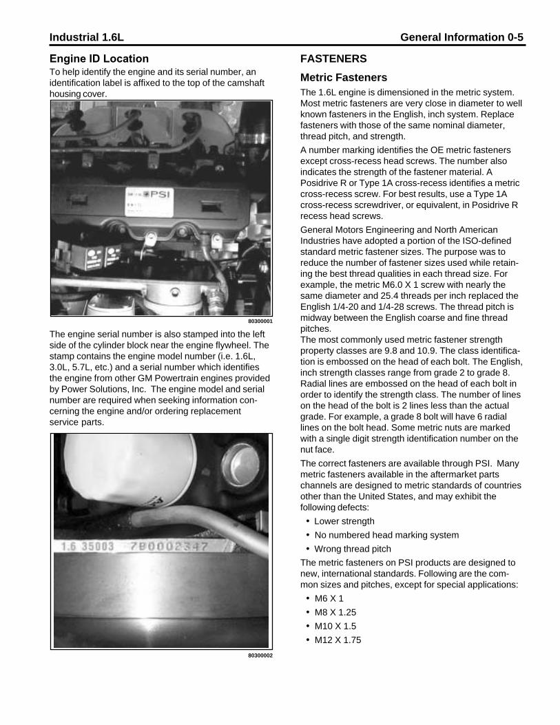
The engine serial number is also stamped into the leftside of the cylinder block near the engine flywheel. Thestamp contains the engine model number (i.e. 1.6L,3.0L, 5.7L, etc.) and a serial number which identifiesthe engine from other GM Powertrain engines providedby Power Solutions, Inc. The engine model and serialnumber are required when seeking information con-cerning the engine and/or ordering replacementservice parts.
80300001
80300002

0-6 General Information Industrial 1.6L
Fastener Strength Identification
Legend(1) English Bolt, Grade 2 (Strength Class) (4) English Bolt, Grade 8 (Strength Class)(2) English Bolt, Grade 5 (Strength Class) (5) Metric Nut, Strength Class 9(3) English Bolt, Grade 7 (Strength Class) (6) Metric Bolts, Strength Class Increases as Numbers Increase
171891

Industrial 1.6L General Information 0-7
Prevailing Torque Fasteners A prevailing torque nut is designed in order to developan interface between the nut and bolt threads. Distor-tion of the top of the metal nut or using a nylon patchon the threads in the middle of the hex flat causes thatinterface.A prevailing torque bolt/nut that is clean and free of rustmay be reused. If there is any doubt, replace thefastener:
1. Clean away all dirt or foreign material.2. Inspect the fastener for signs of overtightening.3. Hand start the fastener at the original location.4. Inspect the fastener for torque development,
referring to the table below.5. Tighten the fastener within specifications.
Legend(1) Prevailing Torque Nut, Center Lock Type(2) Prevailing Torque Nut, Top Lock Type(3) Prevailing Torque Nut, Nylon Patch Type(4) Prevailing Torque Nut, Nylon Washer Insert Type(5) Prevailing Torque Nut, Nylon Insert Type(6) Prevailing Torque Bolt, Dry Adhesive Coating Type(7) Prevailing Torque Bolt, Thread Profile Deformed Type(8) Prevailing Torque Bolt, Nylon Strip Type(9) Prevailing Torque Bolt, Out-of-Round
Thread Area Type
171892

0-8 General Information Industrial 1.6L
SpecificationApplication Metric English
Nuts and All Metal Bolts/Screws 0.250 in 0.4 N•m 4 lb in 0.312 in 0.6 N•m 5 lb in 0.375 in 1.4 N•m 12 lb in 0.437 in 1.6 N•m 16 lb in 0.500 in 2.4 N•m 21 lb in 0.562 in 3.2 N•m 28 lb in 0.625 in 4.2 N•m 37 lb in 0.750 in 7.0 N•m 62 lb inAdhesive or Nylon Coated Bolts/Screws 0.250 in 0.4 N•m 4 lb in 0.312 in 0.6 N•m 5 lb in 0.375 in 1.0 N•m 9 lb in 0.437 in 1.4 N•m 12 lb in 0.500 in 1.8 N•m 16 lb in 0.562 in 2.6 N•m 23 lb in 0.625 in 3.4 N•m 30 lb in 0.750 in 5.2 N•m 49 lb in
Prevailing Torque Specifications (Metric�Size Fasteners)
Prevailing Torque Specifications (English�Size Fasteners)
SpecificationApplication Metric English
Nuts and All Metal Bolts/Screws 6 mm 0.4 N•m 4 lb in 6.3 mm 0.4 N•m 4 lb in 8 mm 0.6 N•m 7 lb in 10 mm 1.4 N•m 12 lb in 12 mm 2.2 N•m 18 lb in 14 mm 3.0 N•m 27 lb in 16 mm 4.2 N•m 37 lb in 20 mm 7.0 N•m 62 lb inAdhesive or Nylon Coated Bolts/Screws 6 mm 0.4 N•m 4 lb in 6.3 mm 0.4 N•m 4 lb in 8 mm 0.6 N•m 7 lb in 10 mm 1.2 N•m 11 lb in 12 mm 1.6 N•m 14 lb in 14 mm 2.4 N•m 21 lb in 16 mm 3.4 N•m 30 lb in 20 mm 5.6 N•m 50 lb in
Industrial 1.6L General Information 0-9
THREAD INSERTS
Repair Procedure
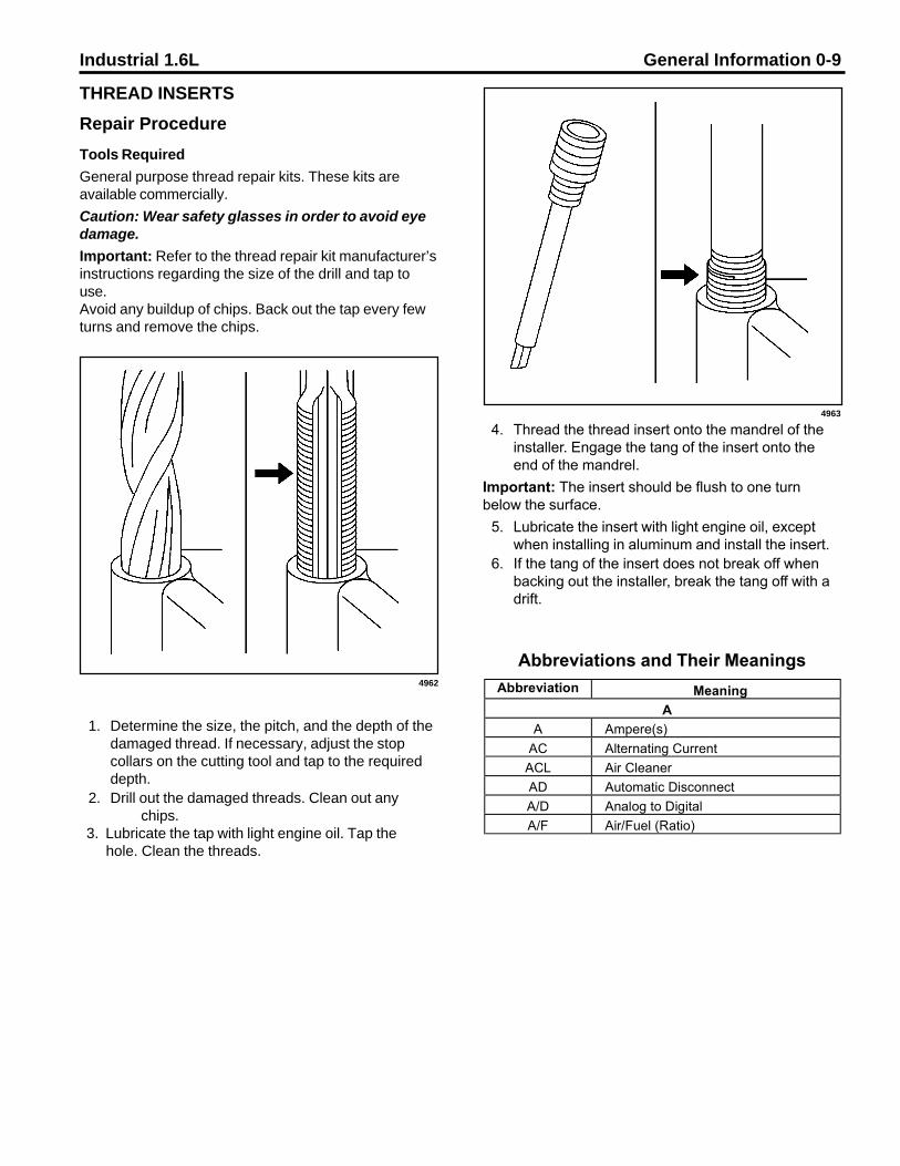
Tools RequiredGeneral purpose thread repair kits. These kits areavailable commercially.Caution: Wear safety glasses in order to avoid eyedamage.Important: Refer to the thread repair kit manufacturer’sinstructions regarding the size of the drill and tap touse.Avoid any buildup of chips. Back out the tap every fewturns and remove the chips.
1. Determine the size, the pitch, and the depth of thedamaged thread. If necessary, adjust the stopcollars on the cutting tool and tap to the requireddepth.
2. Drill out the damaged threads. Clean out anychips.
3. Lubricate the tap with light engine oil. Tap the hole. Clean the threads.
4. Thread the thread insert onto the mandrel of theinstaller. Engage the tang of the insert onto theend of the mandrel.
Important: The insert should be flush to one turnbelow the surface.
5. Lubricate the insert with light engine oil, exceptwhen installing in aluminum and install the insert.
6. If the tang of the insert does not break off whenbacking out the installer, break the tang off with adrift.
Abbreviations and Their MeaningsAbbreviation Meaning
AA Ampere(s)
AC Alternating CurrentACL Air CleanerAD Automatic DisconnectA/D Analog to DigitalA/F Air/Fuel (Ratio)
4962
4963

0-10 General Information Industrial 1.6L
Abbreviations and Their Meanings (cont�d)
Abbreviation MeaningAPCM Accessory Power Control Module
API American Petroleum InstituteAPT Adjustable Part ThrottleASM Assembly, Accelerator and Servo
Control ModuleAuto Automaticavg Average
AWG American Wire GageB
B+ Battery Positive VoltageBARO Barometric (Pressure)BATT BatteryBLK BlackBLU BlueBP Back Pressure
BPCM Battery Pack Control ModuleBRN Brown
BTDC Before Top Dead CenterBTM Battery Thermal Module
CºC Degrees CelsiusCal Calibration
Cam CamshaftCARB California Air Resources Boardcm3 Cubic Centimeters
CCM Convenience Charge Module, ChassisControl Module
CCOT Cycling Clutch Orifice Tube CCPClimate Control Panel
CD Compact Disc
Abbreviations and Their Meanings (cont�d)
Abbreviation MeaningCE Commutator End
CEAB Cold Engine Air Bleedcfm Cubic Feet per Minutecg Center of Gravity
CID Cubic Inch DisplacementCKP Crankshaft PositionCKT CircuitCL Closed Loop
CLS Coolant Level SwitchCMP Camshaft PositionCO Carbon Monoxide
CO2 Carbon DioxideCoax Coaxial
COMM CommunicationConn ConnectorCPA Connector Position AssuranceCPS Central Power SupplyCPU Central Processing UnitCS Charging System
CSFI Central Sequential Fuel InjectionCTP Closed Throttle Positioncu ft Cubic Food/Feetcu in Cubic Inch/Inches
DDAB Delayed Accessory BusdB Decibels
dBA Decibels on A�weighted ScaleDC Direct Current, Duty CycleDI Distributor Ignitiondia DiameterDK Dark

Industrial 1.6L General Information 0-11
Abbreviations and Their Meanings (cont�d) Abbreviations and Their Meanings (cont�d)
Abbreviation MeaningDMM Digital Multimeter
DOHC Dual Overhead CamshaftsE
EC Electrical Center, Engine ControlECL Engine Coolant LevelECM Engine Control Module, Electronic
Control ModuleECS Emission Control SystemECT Engine Coolant Temperature
EEPROM Electrically Erasable ProgrammableRead Only Memory
EFE Early Fuel EvaporationEGR Exhaust Gas Recirculation
EGR TVV Exhaust Gas Recirculation ThermalVacuum Valve
EI Electronic IgnitionELAP ElapsedE/M English/MetricEMF Electromotive ForceEMI Electromagnetic InterferenceEng EngineEOP Engine Oil PressureEOT Engine Oil TemperatureEPA Environmental Protection AgencyEPR Exhaust Pressure Regulator
EPROM Erasable Programmable Read OnlyMemory
ESD Electrostatic DischargeESN Electronic Serial NumberETC Electronic Throttle Control, Electronic
Temperature Control, ElectronicTiming Control
Abbreviation MeaningExh Exhaust
FºF Degrees FahrenheitFC Fan Control
FDC Fuel Data CenterFED Federal (All United States except
California)FEDS Fuel Enable Data Stream
FF Flexible FuelFI Fuel Injection
FMVSS Federal (U.S.) Motor Vehicle SafetyStandards
FP Fuel Pumpft Foot/Feet
FT Fuel TrimFW Flat Wire
GGA Gage, Gaugegal Gallongas GasolineGen GeneratorGL Gear LubricantGM General Motors
GM SPO General Motors Service PartsOperations
gnd Groundgpm Gallons per MinuteGRN GreenGRY Gray
HH Hydrogen
H2O WaterHarn HarnessHC Hydrocarbons
H/CMPR High Compression

0-12 General Information Industrial 1.6L
Abbreviations and Their Meanings (cont�d) Abbreviations and Their Meanings (cont�d)
Abbreviation MeaningHD Heavy Duty
HDC Heavy Duty CoolingHg Mercury
Hi Alt High AltitudeHO2S Heated Oxygen Sensor
hp HorsepowerHz Hertz
IIAC Idle Air ControlIAT Intake Air TemperatureIC Integrated Circuit, Ignition Control
ICM Ignition Control ModuleIDI Integrated Direct Ignitionign IgnitionILC Idle Load Compensatorin Inch/Inches
INJ Injectioninst Instantaneous, InstantISC Idle Speed ControlISO International Standards Organization
Kkg Kilogram
kHz Kilohertzkm Kilometer
km/h Kilometers per Hourkm/l Kilometers per Liter
Abbreviation MeaningkPa KilopascalsKS Knock SensorkV Kilovolts
LL LiterL4 Four Cylinder Engine, In�linelb Pound
lb ft Pound Feet (Torque)lb in Pound Inch (Torque)LCD Liquid Crystal DisplayLED Light Emitting DiodeLH Left HandLT Light
MMAF Mass AirflowMan ManualMAP Manifold Absolute PressureMAT Manifold Absolute Temperaturemax MaximumM/C Mixture ControlMDP Manifold Differential PressureMFI Multiport Fuel InjectionMIL Malfunction Indicator Lampmin MinimummL Millilitermm Millimeterms Millisecond
MST Manifold Surface TemperatureMV MegavoltmV Millivolt

Industrial 1.6L General Information 0-13
Abbreviations and Their Meanings (cont�d) Abbreviations and Their Meanings (cont�d)
Abbreviation MeaningN
NC Normally ClosedNEG NegativeNeu Neutral
NiMH Nickel Metal HydrideNLGI National Lubricating Grease InstituteNm Newton-meter (Torque)NO Normally OpenNOx Oxides of Nitrogen
NPTC National Pipe Thread CoarseNPTF National Pipe Thread Fine
OO2 Oxygen
O2S Oxygen SensorOC Oxidation Converter (Catalytic)
OCS Opportunity Charge StationOD Outside Diameter
ODM Output Drive ModuleOE Original Equipment
OEM Original Equipment ManufacturerOHC Overhead Camshaftohm OhmOL Open Loop, Out of Limits
ORC Oxidation Reduction Converter(Catalytic)
ORN OrangeORVR On-Board Refueling Vapor RecoveryOSS Output Shaft Speedoz Ounce(s)
PPAG Polyalkylene GlycolPAIR Pulsed Secondary AirPC Pressure Control
PCB Printed Circuit BoardPCS Pressure Control SolenoidPCV Positive Crankcase Ventilation
Abbreviation MeaningPIM Power Inverter ModulePM Permanent Magnet (Generator)P/N Part NumberPNK PinkPOA Pilot Operated Absolute (Valve)POS Positive, PositionPOT Potentiometer (Variable Resistor)PPL Purpleppm Parts per Millionpsi Pounds per Square Inch
psia Pounds per Square Inch Absolutepsig Pounds per Square Inch Gaugept Pint
PTC Positive Temperature CoefficientQ
qt Quart(s)R
Ref ReferenceRev ReverseREX Rear ExchangerRH Right HandRly Relay
ROM Read Only Memory (Permanentmemory device, memory contents areretained when power is removed.)

0-14 General Information Industrial 1.6L
Abbreviations and Their Meanings (cont�d) Abbreviations and Their Meanings (cont�d)
Abbreviation MeaningRPM Revolutions per Minute (Engine
Speed)RPO Regular Production OptionRR Right Rear
Ss Second(s)
SAE Society of Automotive EngineersSEO Special Equipment OptionSFI Sequential Multiport Fuel InjectionSI System International (Modern Version
of Metric System)sol Solenoid
SO2 Sulfur DioxideSP Splice Pack
SPO Service Parts Operationssq ft, ft2 Square Foot/Feetsq in, in2 Square Inch/Inches
SRI Service Reminder IndicatorSw Switch
TTAC Throttle Actuator ControlTach TachometerTBI Throttle Body Fuel Injection
Abbreviation MeaningTDC Top Dead Center
TEMP TemperatureTerm TerminalTP Throttle PositionTV Throttle Valve
TVV Thermal Vacuum ValveTWC Three Way Converter (Catalytic)
TWC+OC Three Way + Oxidation Converter(Catalytic)
TXV Thermal Expansion ValveUV
V Volt(s), VoltageVac VacuumV dif Voltage DifferenceVDV Vacuum Delay ValveVIO Violet

Industrial 1.6L General Information 0-15
MAINTENANCE AND LUBRICATIONInitial Start Up MaintenanceThe initial start-up checks must be made before putting the engine into service.Please refer to Maintenance Schedule - 1.6L Engine on page 0-19 and perform the initial start-up operations in thesequence shown in column 1.
Routine MaintenanceRoutine maintenance provides the best solution for making sure that the engine is ready when you are. The followingare some routine service points:
• Keep the fuel tank filled. A full tank of fuel reduces the possibility of condensation forming in the fueltank and moisture entering the fuel system.
• Make frequent checks of the engine oil and coolant levels.• Repair any oil or coolant leaks immediately.• Check battery condition and cables frequently.• Keep the engine air filter clean.• Monitor engine coolant temperature.• Monitor engine oil pressure.
• Check voltmeter and charging system.
Scheduled Preventive MaintenanceRefer to the Maintenance Schedule - 1.6L Engine on page 0-19 to ensure that all of the maintenance items listed arechecked and replaced as recommended at the hours shown.
Engine Oil Level CheckThe engine oil level should be checked daily. It is recommended that the oil be checked just before the engine isstarted for the first time for that day. The oil level should be between the ‘Add’ and the ‘Full’ marks on the dipstick.CAUTION: Do not operate the engine with the oil level below the bottom or ‘Add’ mark on the dipstick, orabove the top or ‘Full’ mark on the dipstick.
Adding Engine OilIt is normal to add some oil in the period of time between oil changes. The amount will vary with the severity ofoperation. When adding or replacing engine oil, be sure the oil meets or exceeds the recommended specification.
Engine Oil and FilterThe engine oil and filter must be changed every 200 hours or every 3 months whichever occurs first. Under normaloperating conditions, you do not need to change them more often if you use oil and filters of the recommended quality.The oil and filter should be changed more often if the engine is operating in dusty or extremely dirty areas, or duringcold weather. No oil additives or break-in oil change is required.
Engine Oil QualityTo achieve proper engine performance and durability, it is important that you use only engine lubricating oils of thecorrect quality in your engine. Proper quality oils also provide maximum efficiency for crankcase ventilation systems,which reduces pollution.Important: use only engine oils displaying the American Petroleum Institute (API) “Starburst” Certification Mark‘FOR GASOLINE ENGINES’ on the container.Gasoline engines that are converted for LPG or NG fuels MUST use oils labeled ‘FOR GASOLINE ENGINES’. Donot use oils that are specifically formulated for Diesel Engines only. CC or CD classification oils, even when labeledHeavy Duty or for Natural Gas Engines, ARE NOT ACCEPTABLE.

0-16 General Information Industrial 1.6L
Engine Oil RecommendationMulti-viscosity oils are recommended. SAE 10W30 is recommended for your engine from 0 degrees F (-18 degrees C)or above. If ambient temperatures are consistently below 0 degrees F, SAE 5W30 oil can be used. Synthetic oils arenot recommended for industrial or stationary engines.
Oil FilterThe PSI GM Powertrain engines use an AC Delco oil filter as original equipment. An equivalent oil filter must be usedwhen servicing the engine (see Engine Specifications for the recommended oil filter for your engine).The filter protects your engine from harmful, abrasive, or sludgy particles without blocking the flow of oil to vital engineparts.To replace the filter, use a proper filter wrench to remove the filter.Clean the filter mounting base and lightly coat the gasket surface of the new filter with engine oil. Hand tighten thefilter until the gasket contacts the base, then tighten another ½ turn. Fill the engine with the correct amount of oil, runthe engine and check for oil leaks at the drain plug and oil filter gasket. Tighten as necessary to stop any oil leakagenoted.
Engine Air CleanerThe engine air cleaner filters air entering the engine intake system and acts as a silencer and flame arrester whenassembled to the intake system.Air that contains dirt and grit produces an abrasive fuel mixture and can cause severe damage to the cylinder wallsand piston rings. Damage to the cylinder walls and piston rings will cause high oil consumption and shorten enginelife.A restricted or dirty air cleaner will also cause a rich fuel mixture. Thus, it is extremely important that the air cleaner beserviced properly at the recommended intervals.CAUTION: Service the air cleaner more frequently under severe dusty or dirty conditions.Remove the primary air cleaner element from the air cleaner assembly and inspect the element for foreign materialrestrictions or signs of excessive wear or damage. Replace the element if necessary.Remove all dust and foreign matter from the air cleaner housing.Reinstall the air cleaner element. Reinstall the air cleaner cup, and securely fasten the retaining clips.
Safety ElementIf your engine is equipped with an air cleaner which utilizes a safety element, ensure that the element is properly inplace before installing the primary element. Change the safety element annually.
COOLING SYSTEM MAINTENANCECoolant LevelCheck the coolant level of the radiator daily and only when the engine is cool. Generally a good time to do this is justprior to starting the engine for the first time each day.Maintain the coolant level at ¾ to 1½ inches below the filler neck seat of the radiator when the coolant is cold. Whenever coolant level checks are made inspect the condition of the radiator cap rubber seal. Make sure it is clean and freeof any dirt particles which would keep it from seating on the filler neck seat. Rinse off with clean water if necessary.Also make sure that the filler neck seat is free of any dirt particles.Caution: Never remove the radiator cap under any conditions while the engine is operating. Failure to followthese instruction could result in damage to the cooling system, engine, or cause personal injury. To avoidhaving scalding hot coolant or steam blow out of the radiator, use extreme caution when removing theradiator cap from a hot radiator. If possible, wait until the engine has cooled, then wrap a thick cloth aroundthe radiator cap and turn slowly to the first stop. Step back while the pressure is released from the coolingsystem. When all the pressure has been released, press down on the cap and remove it slowly.Notice: DO NOT add coolant to any engine that has become overheated until the engine cools. Adding coolant to anextremely hot engine can result in a cracked block or cylinder head.

Industrial 1.6L General Information 0-17
Coolant Level - ContinuedUse only a permanent-type coolant when refilling or flushing the coolant system.Recommended ethylene glycol mix 52/48 is normal up to a maximum of 60% glycol, 40% water.Refer to the mixture chart on the container for additional antifreeze protection information. DO NOT use alcohol ormethanol antifreeze, or mix them with the specified coolant.Plain water may be used in an emergency (except in freezing temperatures), but replace it with the specified coolantas quickly as possible to avoid damage to the system.
RadiatorInspect the exterior of the radiator for obstructions. Remove all bugs, dirt or foreign material with a soft brush or cloth.Use care to avoid damaging the core fins. If available, use low pressure compressed air or a stream of water in theopposite direction of the normal air flow.
Radiator HosesCheck all hoses and connections for leaks. If any of the hoses are cracked, frayed, or feel spongy, they must bereplaced.
Fan BeltsThe water pump is usually belt driven. The same belt may also drive the fan and/or the alternator. The drive beltsshould be properly adjusted at all times. A loose belt can cause improper alternator, fan and water pump operation, inaddition to overheating.
Serpentine BeltSome GM Powertrain engines utilize serpentine belts on the front of the engine. This type of belt system incorporatesa belt tensioning device which keeps the belt at the proper tension.This belt should be checked routinely for cracks or ‘checking’ on the groove side of the belt. If cracks or ‘checking’ areapparent the belt must be changed.
V-Type BeltV-Type belts are generally tensioned by adjusting the alternator position, or through a mechanical belt tensioner. The belt is generally correctly tensioned when there is an ½ inch of depression on the belt between thewater pump and the crankshaft pulley.
FUEL DELIVERY SYSTEM MAINTENANCE
Fuel Filter ReplacementCarbureted EnginesOn carbureted engines, an in-line fuel filter is incorporated into the fuel supply line. It is recommended that this filter bechanged every 250 hours or every 6 months which ever occurs first.
TBI EnginesOn PSI Fuel Injection or Fuel Injection/Dual Fuel two fuel filters are used in the gasoline fuel supply line to the engineTBI unit. A coarse fuel filter is located in the supply line between the fuel tank and the electric fuel pump. This filterprotects the fuel pump from debris in the fuel tank. This filter must be changed every 200 hours or every 6 monthswhich ever occurs first.A primary fuel filter is located between the fuel pump and the TBI unit on the engine. This filter protects the injectorsfrom microscopic particles in the fuel which can cause plugging of the injectors. This filter MUST be changed every500 hours or annually which ever occurs first.
Zenith Z.E.E.M.S. TBI Fuel InjectionZenith Z.E.E.M.S. TBI Fuel Injection requires an in-line fuel filter in the fuel supply line from the fuel tank to the TBIunit, ahead of the electric fuel supply pump. This filter must be changed every 400 hours or every 6 months which everoccurs first.On engines equipped to run on LPG, the in-line fuel filter must be replaced every 800 hours.

0-18 General Information Industrial 1.6L
Fuel Delivery System Maintenance - ContinuedCAUTION: Failure to change the fuel system filters as recommended can result in premature failure of the TBIfuel system components.NOTE: Some original equipment manufacturers install their own fuel systems. Please refer to the manufacturersmanual if the gasoline fuel system is different than described here.WARNING: Use extreme care when changing the fuel filters on gasoline engines. Gasoline is highly flam-mable and should not be exposed to open flame, sparks, or hot engine components. Allow the engine to coolto ambient temperatures prior to changing fuel filters.
Ignition SystemsTypes of Ignition SystemsThree types of ignition systems are used on PSI GM Powertrain engines. Solid state electronic distributor, solid stateelectronic distributor with ECU (Electronic Control Unit) and distributorless electronic ignition (DIS) with ECU.
Please refer to the Section 3, Engine Electrical, for a description of the ignition system used on your particularengine.
Ignition TimingProper adjustment of the ignition timing must be obtained to provide the optimum engine power output and economy.However, since the 1.6L engine uses a distributorless ignition system which is controlled entirely by the electroniccontrol unit, or ECU, the ignition timing cannot be adjusted by the user. Refer to Section 3, Engine Electrical, for adescription of the distributorless ignition system.
Spark PlugsSpark plugs should be replaced at the recommended intervals described in the Maintenance Schedule. Use only therecommended spark plug or an equivalent as described in Section 3, Engine Electrical.Spark plug gap, should be adjusted as recommended in Section 3, Engine Electrical.When removing spark plugs, always note which cylinder each plug came out of. Look at the porcelain around thecenter electrode of each plug. You can detect many engine problems from the color and type of deposits that havebuilt up on the white porcelain. For example, if the deposits are a glossy brown, that cylinder is burning excess oil. Ifthe deposits are a very dark gray or sooty black color, your engine is running rich, and you are burning excess fuel.The optimum color of the deposits on the porcelain is light tan or light brown. This shows optimum fuel mixture andproper engine running conditions. If the deposits are almost white, the engine may be running excessively lean. Leanrunning is very detrimental to your engine life, and should be corrected immediately.If one or more cylinders are burning oil, the smoke from the engine will be a blue-gray color. Most common causes arepiston rings (worn out or not broken in) and valve stem seals (cut, nicked, or worn out). If the engine is running richthe exhaust smoke will be a sooty black color and it will smell like gasoline (on gasoline engines).

Industrial 1.6L General Information 0-19
MAINTENANCE SCHEDULE - 1.6L ENGINE
Approximate Fluid Capacities
InitialStart-Up
SequenceChecks
Operation Daily Weekly Every50
hrs
Every100hrs
Every200hrs
Every400hrs
Every800hrs
AsReq.
1 Check Engine Oil Level x2 Check Coolant Level x3 Check for Fluid Leaks x4 Governor, Mechanical (Check oil
level)(2)x
Change Engine Oil & Filter (1) x5 Battery, Check Charge & Fluid Level x
Inspect & Clean Radiator Exterior xClean Battery Cables x
6 Check Belts and Belt Tension xLubricate Throttle, Governor & ChokeLinkage (Carbureted Engines Only)
x
Check & Adjust Idle Speed (CarburetedEngines Only)
x
Inspect and Clean Air Cleaner Element xReplace Primary Air Cleaner Element(1)
x
Replace Safety Air Cleaner Element xCheck Coolant Protection & TightenHose Clamps
x
Replace Engine Coolant (3) xReplace Gasoline Fuel Filter (4) xReplace LPG Filter – Zenith EFI (4) xReplace PCV Valve (If Equipped) xCheck PCV Hoses, Tubes, and Fittings xReplace Spark Plugs (3) xDistributor Cap & Rotor (5) xSecondary Ignition Wires xAdjust Throttle & Governor (3) x
7 Check All Engine Bolts & Nuts forTightness
x
Application SpecificationMetric English
Engine Cooling System 1.6L W ithout Radiator 3.3 L 3.5 qts. 1.6L W ith Radiator 9.5 L 10.0 qts.Engine Crankcase 1.6L W ith Filter 3.5 L 3.7 qts. 1.6L W ithout Filter 3.2 L 3.4 qts.
(1) More frequent intervals may be required in dusty or dirty operating conditions.(2) Mechanical governor (belt driven).(3) To be performed at specified interval or annually, whichever occurs first.(4) More frequent intervals may be required with dirt in the fuel system.(5) Does not apply to engines with DIS ignition.

0-20 General Information Industrial 1.6L
FILTER CHART - 1.6L ENGINE
Engine 1.6LOil Filter 94632619
Fuel Filter(Carbureted) N/A
Fuel Filter(PSI TBI Coarse) N/A
Fuel Filter(PSI TBI Fine) N/A
Fuel FilterZenith Z.E.E.M.S
GasolineC282-224
LPGC282-5
Air FilterPrimary
(PSI Power Unit)N/A
Air Filter Safety(PSI Power Unit)
N/A
25010792

Industrial 1.6L Engine Mechanical 1-1
Section 1Engine Mechanical
Fastener Notice .......................................................... 1-2Engine Mechanical - 1.6L ........................................ 1-3Specifications ........................................................... 1-3Fastener Tightening Specifications ............................. 1-4Sealers, Adhesives and Lubricants ............................ 1-6Engine Mechanical Specifications .............................. 1-7Engine Identification Code/Engine Number ................. 1-7Engine Management .................................................. 1-7Cylinder Head ............................................................ 1-8Crank Drive, Cylinder Block ..................................... 1-10Diagnostic Information and Procedures ............... 1-17Tension Check, Ribbed V-belt .................................. 1-17Engine Compression Test ........................................ 1-17Engine Loss of Compression Test ........................... 1-18Oil Pressure Check .................................................. 1-19Timing Check ........................................................... 1-20Timing Adjustment ................................................... 1-20Toothed Belt Tension Check .................................... 1-23Toothed Belt Tension Adjust .................................... 1-24Repair Instructions................................................. 1-25Engine Timing Side .................................................. 1-25Ribbed V-belt, Remove and Install ........................... 1-25Toothed Belt Cover, Upper Part, Remove and Install 1-26Toothed Belt Cover, Lower Part, Remove and Install 1-27Toothed Belt, Remove and Install ............................ 1-28Toothed Belt Tension Roller, Remove and Install ..... 1-29Seal Ring in Front Camshaft Housing, Replace ........ 1-30Rear Toothed Belt Cover, Remove and Install .......... 1-32Cylinder Head .......................................................... 1-34Seal Ring in Rear Camshaft Housing, Replace ......... 1-34Exhaust Manifold, Remove and Install ..................... 1-35Intake Manifold, Remove and Install - Port Fuel Injected
Models ............................................................... 1-36Intake Manifold, Remove and Install - Throttle Body Fuel
Injected Models .................................................. 1-38Heat Shields, Remove and Install ............................ 1-40Camshaft and Cam Follower, Remove and Install (Cylinder head Installed) ..................................... 1-40Hydraulicd Valve Lifter, Replace (Cylinder Head Installed) ............................................................ 1-43Camshaft, Remove and Install (Cylinder Head Removed) .......................................................... 1-44Camshaft Housing, Replace ..................................... 1-44Camshaft Housing, Check for Plane Surface ........... 1-47Cylinder Head, Remove and Install .......................... 1-47Cylinder Head, Check for Plane Surface .................. 1-53Crank Drive, Cylinder Block ..................................... 1-54
Drive Disc, Remove and Install ................................ 1-54Flywheel, Remove and Install .................................. 1-54Seal Ring - Rear Crankshaft, Replace ...................... 1-55Engine Vent Flange or Gasket, Remove and Install . 1-56Piston with Con-rod, Remove and Install .................. 1-57Piston Rings, Remove and Install ............................ 1-61Con-rod Bearing, Replace ........................................ 1-63Con-rod Bearing Clearance, Check (DetermineBearing Clearance with 50 Plastigage) ..................... 1-64Con-rod Bearing Clearance, Check (Determine Bearing
Clearance with Micrometer and Inside Micrometer) ........................................................ 1-65Piston, Replace ....................................................... 1-66Crankshaft, Remove and Install ............................... 1-68Crankshaft, Check ................................................... 1-70Crankshaft End Clearance, Check ........................... 1-70Crankshaft Out-of-round, Check ............................... 1-70Crankshaft Bearing Play, Check (Determine Bearing Play with Plastigage) ......................................... 1-70Crankshaft Bearing Clearance, Check (Determine Crankshaft Bearing Clearnace Using External Micrometer and Inside Micrometer) .................... 1-71Cylinder Block, Check for Plane Surface ................. 1-72Oil Circuit ................................................................. 1-73Oil Filter, Replace .................................................... 1-73Bypass Valve, Replace ............................................ 1-73Front Seal Ring - Crankshaft, Replace ..................... 1-73Oil Pan, Remove and Install .................................... 1-76Oil Pump, Remove and Install .................................. 1-77Oil Pump, Check ...................................................... 1-79Safety Valve, Remove and Install ............................ 1-81Oil Intake Pipe, Remove and Install ......................... 1-81Oil Baffle Plate, Remove and Install ........................ 1-82Oil Pressure Switch, Remove and Install ................. 1-82Oil Dipstick Tube, Remove and Install ..................... 1-83Crankshaft Position Sensor, Remove and Install ..... 1-83Reference Gap Between Crankshaft Position Sensor and Increment Disc, Check ............................... 1-83Coolant Thermostat, Remove and Install ................. 1-84Coolant Pump, Remove and Install .......................... 1-84Fuel Pressure Check ............................................... 1-84Coolant Temperature Sensor, Remove and Install .... 1-85Starter ...................................................................... 1-86Starter, Remove and Install ...................................... 1-86Alternator ................................................................. 1-86Alternator, Remove and Install ................................. 1-86Special Tools and Equipment ............................... 1-88

1-2 Engine Mechanical Industrial 1.6L
Fastener NoticeNOTICE: Always use the correct fastener in the proper location. When you replace a fastener, use ONLY the exact partnumber of that application.
PSI will call out those fasteners that require a replacement after removal. PSI will also call out the fasteners that requirethread lockers or thread sealant.
UNLESS OTHERWISE SPECIFIED, Do Not use supplemental coatings (paints, greases or other corrosion inhibitors) onthreaded fasteners or fastener joint interfaces. Generally, such coating adversely affect the fastener torque and the jointclamping force, and may damage the fastener.
When you install fasteners, use the correct tightening sequence and specifications.
Following these instructions can help you avoid damage to parts and systems.

Industrial 1.6L Engine Mechanical 1-3
SpecificationsSpecification
Engine Z16 SE 1.6L Industrial Metric EnglishNumber of cylinders/layout 4 In LineNumber of valves 8Capacity 1598 cm3 97.5 cu inBore Diameter 79 mm 3.11 inStroke 81.5 mm 3.2 inPower Output 62 KW @ 5400 rpm 46.2 Hp @ 5400 rpmTorque 138 N•m @ 2600
rpm101.8 lb ft @ 2600
rpmCompression 9.6:1
Engine Mechanical - 1.6L
Engine 1.6L Industrial
9.4:1

1-4 Engine Mechanical Industrial 1.6L
Fastener Tightening Specifications
SpecificationApplication Metric English
Starter to cylinder block 40 N@m 13 lb ftDrive disc to crankshaft 25 N@m 18 lb ftExhaust manifold to cylinder head 55 N@m + 30º + 15º 1) 106 lb inCamshaft sensor fastening bolt to camshaft housing 18 N@m 13 lb ftDIS Ignition Module to camshaft housing carrier 18 N@m 13 lb ftThrottle valve injection housing to intake manifold 10 N@m 89 lb inUpper part of throttle valve injection housing to throttlevalve injection housing
10 N@m 89 lb in
Throttle body to intake manifold 2 N@m 18 lb inPressure plate to camshaft housing 8.5 N@m 75 lb inIntake manifold to cylinder head 22 N@m 16 lb ftAlternator to alternator support 1.5 N@m 13 lb inAlternator to alternator shackle 1.5 N@m 13 lb inAlternator support to cylinder block 25 N@m 18 lb ftCrankshaft pulse pickup bracket to oil pump 4.5 N@m 40 lb inWiring harness bracket to intake manifold 2 N@m 18 lb inRear toothed belt cover to camshaft housing 16 N@m 12 lb ftRear toothed belt cover to oil pump and camshaft housing 2.8 N@m 25 lb inHeat shield to exhaust manifold 50 N@m 37 lb ftHeat shield sleeves (sparkplugs) to cylinder head 9 N@m 80 lb inCrankshaft pulse pickup to bracket 35 N@m 26 lb ftIncrement disc to toothed belt drive gear 8.5 N@m 75 lb inWiring trough to cylinder head 8 N@m 71 lb inKnock sensor to cylinder head 20 N@m 15 lb ft
SpecificationApplication Metric English
Fuel supply and return line to throttle valve guards 15 N@m 11 lb ftCoolant pump to cylinder block 8 N@m 71 lb inCoolant pipe to cylinder block 20 N@m 15 lb ftCrankshaft bearing cap to cylinder block 50 N@m + 45º + 15º 1) 37 lb ftAlternator shackle to intake manifold 20 N@m 15 lb ftFan housing to radiator 5 N@m 44 lb inCamshaft housing cover to camshaft housing 8 N@m 71 lb inCamshaft sprocket to camshaft 45 N@m 33 lb ftOil drain bolt to oil pan 55 N@m 41 lb ftOil pressure switch to oil pump 30 N@m 22 lb ftOil filter to oil pump 15 N@m 11 lb ftOil pump to cylinder block 10 N@m 89 lb inOil pump cover to oil pump 6 N@m 53 lb inOil intake pipe to oil pump 8 N@m 1) 71 lb inOil intake pipe to cylinder block 8 N@m 71 lb inOil baffle plate to oil pan 8 N@m 71 lb in

Industrial 1.6L Engine Mechanical 1-5
Fastener Tightening Specifications (Continued)
SpecificationApplication Metric English
Fuel supply and return line to throttle valve guards 15 N@m 11 lb ftCoolant pump to cylinder block 8 N@m 71 lb inCoolant pipe to cylinder block 20 N@m 15 lb ftCrankshaft bearing cap to cylinder block 50 N@m + 45º + 15º 1) 37 lb ftAlternator shackle to intake manifold 20 N@m 15 lb ftFan housing to radiator 5 N@m 44 lb inCamshaft housing cover to camshaft housing 8 N@m 71 lb inCamshaft sprocket to camshaft 45 N@m 33 lb ftOil drain bolt to oil pan 55 N@m 41 lb ftOil pressure switch to oil pump 30 N@m 22 lb ftOil filter to oil pump 15 N@m 11 lb ftOil pump to cylinder block 10 N@m 89 lb inOil pump cover to oil pump 6 N@m 53 lb inOil intake pipe to oil pump 8 N@m 1) 71 lb inOil intake pipe to cylinder block 8 N@m 71 lb inOil baffle plate to oil pan 8 N@m 71 lb inOil pan to oil pump 10 N@m 1) 89 lb inOil pan to cylinder block 10 N@m 1) 89 lb inCon-rod bearing cap to con-rod 25 N@m + 30º 3) 18 lb ftFlywheel to crankshaft 35 N@m + 30º + 15º 1) 26 lb ftCoolant temperature sensor to intake manifold 20 N@m 15 lb ftSupport to alternator and intake manifold 20 N@m 15 lb ftThermostat housing to cylinder head 10 N@m 89 lb inCarrier plate (DIS ignition module) to camshaft housing 12 N@m 106 lb inClosure bolt, safety valve to oil pump 50 N@m 37 lb ftFront exhaust pipe to exhaust manifold (hex bolts) 35 N@m 2) 26 lb ftFront exhaust pipe to exhaust manifold (hex nuts) 45 N@m 3) 33 lb ftToothed belt cover � upper part to rear toothed belt cover 4 N@m 35 lb inToothed belt cover � lower part to rear toothed belt cover 4 N@m 35 lb inToothed belt tension roller to oil pump 20 N@m 37 lb ftSpark plug to cylinder head 25 N@m 18 lb ftCylinder head and camshaft housing to cylinder block 25 N@m + 85º + 85º 2) 18 lb ft
1) Use new bolts.2) Insert bolts with mounting paste (white).3) Use new nut(s).

1-6 Engine Mechanical Industrial 1.6L
Sealants, Adhesives, and Lubricants
E n g in e 1 .6 L Z 1 6 L EC r a n k s h a f t D im e n s io n s M a in B e a r in g J o u r n a ls 1 -5 C o lo r C o d e
5 4 .9 8 0 � 5 4 .9 9 7 m m 2 .1 6 4 6 � 2 .1 6 5 2 in b ro w nS ta n d a rd s iz e5 4 .9 8 0 � 5 4 .9 9 7 m m 2 .1 6 4 6 � 2 .1 6 5 2 in g re e n5 4 .7 3 0 � 5 4 .7 4 7 m m 2 .1 5 4 7 � 2 .1 5 5 4 in b ro w n /b lu eU n d e rs iz e (0 .2 5 )5 4 .7 3 0 � 5 4 .7 4 7 m m 2 .1 5 4 7 � 2 .1 5 5 4 in g re e n /b lu e5 4 .4 8 2 � 5 4 .4 9 5 m m 2 .1 4 5 0 � 2 .1 4 5 5 in b ro w n /w h iteU n d e rs iz e (0 .5 0 )5 4 .4 8 2 � 5 4 .4 9 5 m m 2 .1 4 5 0 � 2 .1 4 5 5 in g re e n /w h ite
C o n -ro d b e a r in g jo u rn a lS ta n d a rd s iz e 4 2 .9 7 1 � 4 2 .9 8 7 m m 1 .6 9 1 8 � 1 .6 9 2 4 in -
U n d e rs iz e (0 .2 5 ) 4 2 .7 2 1 � 4 2 .7 3 7 m m 1 .6 8 1 9 � 1 .6 8 2 6 in b lu eU n d e rs iz e (0 .5 0 ) 4 2 .4 7 1 � 4 2 .4 8 7 m m 1 .6 7 2 1 � 1 .6 7 2 7 in w h ite
W id e m a in b e a r in g jo u r n a lsS ta n d a rd s iz e 2 6 .0 0 0 � 2 6 .0 5 2 m m 1 .0 2 4 � 1 .0 2 6 in -
U n d e rs iz e (0 .2 0 ) 2 6 .2 0 0 � 2 6 .2 5 2 m m 1 .0 3 1 � 1 .0 3 4 in -U n d e rs iz e (0 .4 0 ) 2 6 .4 0 0 � 2 6 .4 5 2 m m 1 .0 3 9 � 1 .0 4 1 in -

Industrial 1.6L Engine Mechanical 1-7
Engine Mechanical Specifications
Engine Identification Code / Engine NumberThe engine identification code is embossed on the flattenedarea (arrow) of the cylinder block on the upper rear side.
Engine Management
Engine D isplacem ent 1.6LEngine Designation M ultec-S Z 16 SEIgnition Sequence 1-3-4-2
Spark P lugs FLR 8 LDCU

1-8 Engine Mechanical Industrial 1.6L
Cylinder Head
Illustration1 Cylinder head height2 Installation height of valve guide3 Installation height of valve4 Valve seat width in cylinder head5 Valve seat angle in cylinder head6 Valve stem diameter7 Valve seat angle at valve8 Valve length9 Valve head – diameter
Cylinder Head
Industrial 1.6L Engine Mechanical 1-9
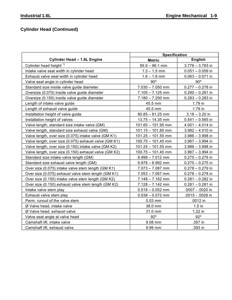
Cylinder Head (Continued)
SpecificationCylinder Head � 1.6L Engine Metric English
Cylinder head height 1) 95.9 � 96.1 mm 3.776 � 3.783 inIntake valve seat width in cylinder head 1.3 � 1.5 mm 0.051 � 0.059 inExhaust valve seat width in cylinder head 1.6 � 1.8 mm 0.063 � 0.071 inValve seat angle in cylinder head 90º 90ºStandard size inside valve guide diameter 7.030 � 7.050 mm 0.277 � 0.278 inOversize (0.075) inside valve guide diameter 7.105 � 7.125 mm 0.280 � 0.281 inOversize (0.150) inside valve guide diameter 7.180 � 7.200 mm 0.283 � 0.283 inLength of intake valve guide 45.5 mm 1.79 inLength of exhaust valve guide 45.5 mm 1.79 inInstallation height of valve guide 80.85 � 81.25 mm 3.18 � 3.20 inInstallation height of valves 13.75 � 14.35 mm 0.541 � 0.565 inValve length, standard size intake valve (GM) 101.65 � 101.95 mm 4.001 � 4.014 inValve length, standard size exhaust valve (GM) 101.15 � 101.85 mm 3.982 � 4.010 inValve length, over size (0.075) intake valve (GM K1) 101.25 � 101.55 mm 3.986 � 3.998 inValve length, over size (0.075) exhaust valve (GM K1) 100.75 � 101.45 mm 3.967 � 3.994 inValve length, over size (0.150) intake valve (GM K2) 101.25 � 101.55 mm 3.986 � 3.998 inValve length, over size (0.150) exhaust valve (GM K2) 100.75 � 101.45 mm 3.967 � 3.994 inStandard size intake valve length (GM) 6.998 � 7.012 mm 0.275 � 0.276 inStandard size exhaust valve length (GM) 6.978 � 6.992 mm 0.275 � 0.275 inOver size (0.075) intake valve stem length (GM K1) 7.073 � 7.087 mm 0.278 � 0.279 inOver size (0.075) exhaust valve stem length (GM K1) 7.053 � 7.067 mm 0.278 � 0.278 inOver size (0.150) intake valve stem length (GM K2) 7.148 � 7.162 mm 0.281 � 0.282 inOver size (0.150) exhaust valve stem length (GM K2) 7.128 � 7.142 mm 0.281 � 0.281 inIntake valve stem play 0.018 � 0.052 mm .0007 - .0020 inExhaust valve stem play 0.038 � 0.072 mm .0015 - .0028 inPerm. runout of the valve stem 0.03 mm .0012 inØ Valve head, intake valve 38.0 mm 1.5 inØ Valve head, exhaust valve 31.0 mm 1.22 inValve seat angle at valve head 92º 92ºCamshaft lift, intake valve 9.08 mm .357 inCamshaft lift, exhaust valve 9.99 mm .393 in

1-10 Engine Mechanical Industrial 1.6L
Crank Drive, Cylinder Block
Illustration
1 Main Bearing Journals2 Con–rod bearing journal3 Main Bearing Journals (Guide Bearing)4 Crankshaft color code5 Bearing shell color code6 Bearing shell identification
Crank Drive, Cylinder Block
Industrial 1.6L Engine Mechanical 1-11
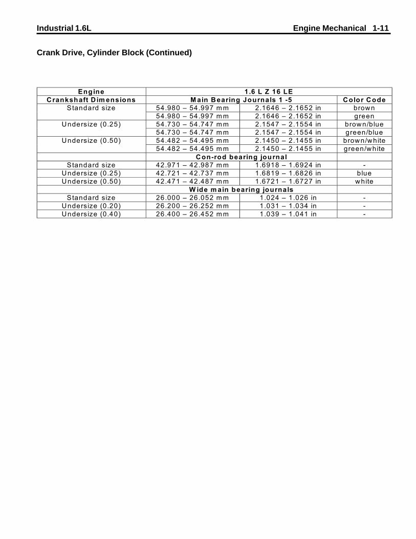
Crank Drive, Cylinder Block (Continued)
Engine 1.6 L Z 16 LECrankshaft D im ensions M ain Bearing Journals 1 -5 Color Code
54.980 � 54.997 m m 2.1646 � 2.1652 in brownStandard size54.980 � 54.997 m m 2.1646 � 2.1652 in green54.730 � 54.747 m m 2.1547 � 2.1554 in brown/blueUndersize (0.25)54.730 � 54.747 m m 2.1547 � 2.1554 in green/blue54.482 � 54.495 m m 2.1450 � 2.1455 in brown/whiteUndersize (0.50)54.482 � 54.495 m m 2.1450 � 2.1455 in green/white
Con-rod bearing journalStandard size 42.971 � 42.987 m m 1.6918 � 1.6924 in -
Undersize (0.25) 42.721 � 42.737 m m 1.6819 � 1.6826 in blueUndersize (0.50) 42.471 � 42.487 m m 1.6721 � 1.6727 in white
W ide m ain bearing journalsStandard size 26.000 � 26.052 m m 1.024 � 1.026 in -
Undersize (0.20) 26.200 � 26.252 m m 1.031 � 1.034 in -Undersize (0.40) 26.400 � 26.452 m m 1.039 � 1.041 in -

1-12 Engine Mechanical Industrial 1.6L
Crank Drive, Cylinder Block (Continued)
Engine 1.6 L Z 16 SELower crankshaft bearing shellCrankshaft bearing
1,2,4,5 Color code Thickness(Metric)
Thickness(English)
CodeGM 400
brown 1.989 � 1.995 mm 0.0783 � 0.0785 in 221 NStandard Sizegreen 1.995 � 2.001 mm 0.0785 � 0.0788 in 201N
brown/blue 2.114 � 2.120 mm 0.0832 � 0.0835 in 222 AUndersize (0.25)green/blue 2.120 � 2.126 mm 0.0835 � 0.0837 in 202 A
brown/white 2.239 � 2.245 mm 0.0881 � 0.0884 in 223 BUndersize (0.50)green/white 2.245 � 2.251 mm 0.0884 � 0.0886 in 203 B
Upper crankshaft bearing shellbrown 1.989 � 1.995 mm 0.0783 � 0.0785 in 221 NStandard Sizegreen 1.995 � 2.001 mm 0.0785 � 0.0788 in 201N
brown/blue 2.114 � 2.120 mm 0.0832 � 0.0835 in 222 AUndersize (0.25)green/blue 2.120 � 2.126 mm 0.0835 � 0.0837 in 202 A
brown/white 2.239 � 2.245 mm 0.0881 � 0.0884 in 223 BUndersize (0.50)green/white 2.245 � 2.251 mm 0.0884 � 0.0886 in 203 B
Perm. bearing clearance - 0.015 � 0.041 mm .00059 - 0.0016 in -Perm. end clearance - 0.100 � 0.202 mm 0.004 � 0.008 in -Perm. out of round - 0.03 mm 0.0012 in -
Lower crankshaft bearing shellCrankshaft bearing3 Color code Thickness
(Metric)Thickness(English)
CodeGM 400
brown 1.989 � 1.995 mm 0.0783 � 0.0785 in 225 NStandard sizegreen 1.995 � 2.001 mm 0.0785 � 0.0788 in 205N
brown/blue 2.114 � 2.120 mm 0.0832 � 0.0835 in 226 AUndersize (0.25)green/blue 2.120 � 2.126 mm 0.0835 � 0.0837 in 206 A
brown/white 2.239 � 2.245 mm 0.0881 � 0.0884 in 227 BUndersize (0.50)green/white 2.245 � 2.251 mm 0.0884 � 0.0886 in 207 B
Upper crankshaft bearing shellbrown 1.989 � 1.995 mm 0.0783 � 0.0785 in 225 NStandard Sizegreen 1.995 � 2.001 mm 0.0785 � 0.0788 in 205 N
brown/blue 2.114 � 2.120 mm 0.0832 � 0.0835 in 226 AUndersize (0.25)green/blue 2.120 � 2.126 mm 0.0835 � 0.0837 in 206 A
brown/white 2.239 � 2.245 mm 0.0881 � 0.0884 in 227 BUndersize (0.50)green/white 2.245 � 2.251 mm 0.0884 � 0.0886 in 207 B

Industrial 1.6L Engine Mechanical 1-13
Crank Drive, Cylinder Block (Continued)
Crank Drive, Cylinder Block (Continued)
Engine 1.6 L Z 16 SELower con-rod bearing shellCon-rod bearing
Color code Thickness(Metric)
Thickness(English)
CodeGM 400
Standard Size - 1.485 � 1.497 mm 0.0585 � 0.0589 in 264 NUndersize (0.25) blue 1.610 � 1.622 mm 0.0634 � 0.0639 in 265 AUndersize (0.50) white 1.735 � 1.747 mm 0.0683 � 0.0688 in 266 B
Upper con-rod bearing shellStandard Size - 1.485 � 1.497 mm 0.0585 � 0.0589 in 264 N
Undersize (0.25) blue 1.610 � 1.622 mm 0.0634 � 0.0639 in 265 AUndersize (0.50) white 1.735 � 1.747 mm 0.0683 � 0.0688 in 266 B
Perm. con-rod play - 0.019 � 0.071 mm .00075 - .00280 in -
Engine 1.6 L Z 16 SE3 wide main bearing
journals (guide bearing)Color code Width
(Metric)Width
(English)Code
GM 400Standard Size green-brown 25.850 � 25.900 mm 1.0177 � 1.0197 in -
brown/blue 26.050 � 26.100 mm 1.0256 � 1.0276 in -Undersize (0.25)green/blue
brown/white 26.250 � 26.300 mm 1.0335 � 1.0354 in -Undersize (0.50)green/white

1-14 Engine Mechanical Industrial 1.6L
Crank Drive, Cylinder Block (Continued)
Illustration
1 Index – identification of cylinder bore2 Cylinder bore3 Double bevelled ring with spiral–type expander4 Tapered compression ring or double trapezoidal ring5 Rectangular compression ring6 Piston diameter
Illustration
Crank Drive, Cylinder Block (Continued)

Industrial 1.6L Engine Mechanical 1-15
Crank Drive, Cylinder Block (Continued)
Engine 1.6 L Z 16 SEC ylinderbore W idth
(M etric)W idth
(English)Standard size
Index 8 78.975 - 78.985 m m 3.1093 � 3.1096 inIndex 99 78.985 - 78.995 m m 3.1096 � 3.1100 inIndex 00 78.995 - 79.005 m m 3.1100 � 3.1104 inIndex 01 79.005 - 79.015 m m 3.1104 � 3.1108 inIndex 02 79.015 - 79.025 m m 3.1108 � 3.1112 in
O versize 1)
Index 7 + 0.5 79.465 - 79.475 m m 3.1285 � 3.1289 inPiston W idth
(M etric)W idth
(English)Standard size
Index 8 78.955 - 78.965 m m 3.1085 � 3.1089 inIndex 99 78.965 - 78.975 m m 3.1089 � 3.1093 inIndex 00 78.975 - 78.985 m m 3.1093 � 3.1096 inIndex 01 78.985 - 78.995 m m 3.1096 � 3.1100 inIndex 02 78.995 - 79.005 m m 3.1100 � 3.1104 in
O versize 1)
Index 7 + 0.5 79.445 - 79.455 m m 3.1278 � 3.1281 inP iston c learance 0.01 � 0.03 m m .00039 - .00118 inP iston pro jection 0.4 m m .01575 in
1) A fter reboring, the o ld index m ust be invalidated and the new oversiz ing index m ust beem bossed.

1-16 Engine Mechanical Industrial 1.6L
Crank Drive, Cylinder Block (Continued)
Engine 1.6 L Z 16 SEPiston R ings Specification (M etric) Specification
(English)Rectangular compression ring
Height 1.20 m m 0.0472 inGap 0.30 � 0.50 m m 0.0118 � 0.0197 in
Vertical p lay 0.02 � 0.04 m m 0.00079 - 0.00157 inTapered com pression ring
Height 1.50 m m 0.059 inGap 0.30 - 0.50 m m 0.0118 � 0.0197 in
Vertical p lay 0.04 � 0.06 m m 0.00157 � 0.00236 inO il scraper ring
Height 3.00 0.1181 inGap 0.40 � 1.40 0.0157 � 0.0551 in
Vertical p lay 0.01 � 0.03 0.00039 � 0.00118 inR ing gap distribution 1) 120º 120º
1) Arrange gap of upper coil scraper ring 25 to 50 mm (1 - 2 in.) offset to the left and gap of the lower ring 25 to 50 mm (1 - 2 in.) offset to the right relative to the gap of the lower intermediate ring.
Engine 1.6 L Z 16 SEPistonpin W idth
(M etric)W idth
(English)Length 5.50 m m 0.2165 in
D iam eter 17.997 � 18.000 m m 0.7085 � 0.7087 inBearing 78.985 - 78.995 m m 3.1096 � 3.1100 in
Clearancein pis ton 0.009 � 0.012 m m .00035 � .00047 in
in con-rod 0.0 m m 0.0 in

Industrial 1.6L Engine Mechanical 1-17
Diagnostic Information and Procedures
Ribbed V–belt Tension, Check
Drive belts must grip the entire contact area of the pully.When drive belts are too loose, the belts can slip, tear,burn, or grab and snap. More belts fail from being tooloose than too tight.Belts that are too tight can damage the engine by causingside loading of the crankshaft, crankshaft bearings, andaccessories or accessory bearings. Too much belttension will also stretch and weaken the belt.When the drive belts are worn, they should be replaced.Tightening worn drive belts will not prevent slipping, andcan also cause damage to the engine.Do not use belt dressings to extend belt life. Mostdressings contain chemicals which soften the belt.
Tools Required:••••• 6” Steel Rule
Engine Compression Test
Removal Procedure1. With engine at operating temperature (oil temperature 80 °C), detach spark plug connectors and remove spark plugs with KM–194–E.
2. Detach wiring harness plug (1) from DIS ignition mod- ule.3. Open relay holder cover and pull fuel pump relay (2) out of base.
Inspect1. Use compression recorder with rubber cone and a mea- suring range of up to 1750 kPa (17.5 bar) overpressure.
2. Actuate starter for approx. 4 seconds with throttle valve fully open – minimum engine speed 300 rpm. The pres- sure difference between the individual cylinders should not exceed 100 kPa (1 bar).
1. Inspect the drive belt for:• Cracks• Glazing• Tears or cuts• Excessive wear
2. Measure the amount of play in the belt. The fan belt should measure approximately 1/2 inch (13 mm) deflec- tion.
1-18 Engine Mechanical Industrial 1.6L
Installation Procedure
1. Insert fuel pump relay in base and close relay holder cover.
2. Connect wiring harness plug to DIS ignition module.
3. Install spark plugs with KM–194–E into cylinder head – Tighten
Tightening torque 25 Nm / 18 lb. ft.
4. Connect spark plug connectors.
Engine Loss of Compression Test
Engine at operating temperature (oil temperature 80 °C).
Removal Procedure
1. Detach spark plug connectors, remove spark plugs with KM–194–E.
2. Remove fluid filler opening sealing cap, coolant com- pensation tank sealing cap and oil dipstick.
3. Remove upper part of toothed belt cover – see operation Toothed Belt Cover – Upper Part, Remove and Install.
Adjust1. Set piston of 1st cylinder to TDC position. To determine TDC position – see operation Timing Check.
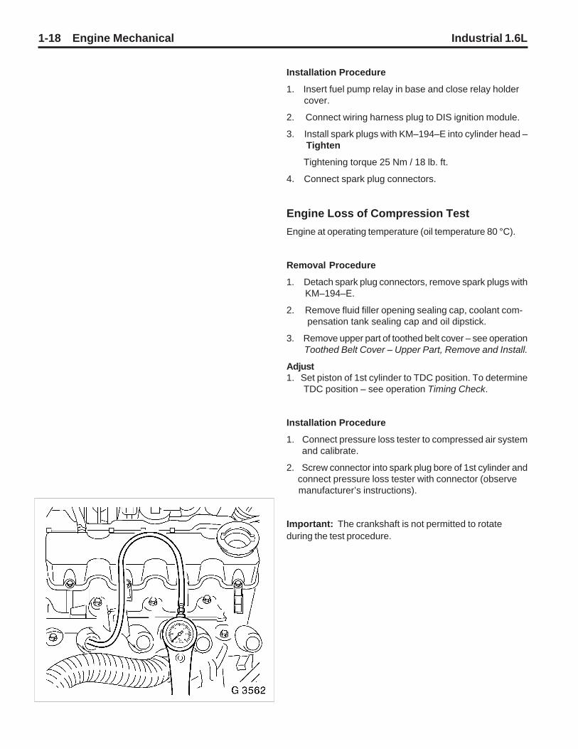
Installation Procedure
1. Connect pressure loss tester to compressed air system and calibrate.
2. Screw connector into spark plug bore of 1st cylinder and connect pressure loss tester with connector (observe manufacturer’s instructions).
Important: The crankshaft is not permitted to rotateduring the test procedure.
Industrial 1.6L Engine Mechanical 1-19
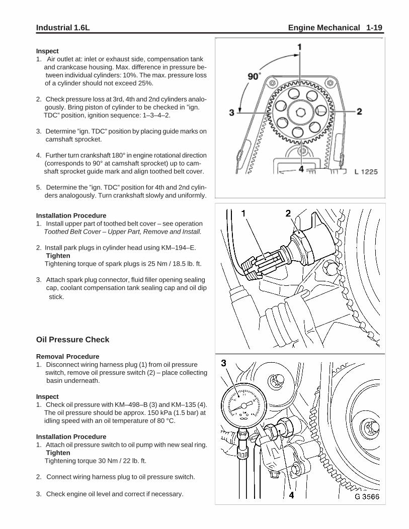
Inspect1. Air outlet at: inlet or exhaust side, compensation tank and crankcase housing. Max. difference in pressure be- tween individual cylinders: 10%. The max. pressure loss of a cylinder should not exceed 25%.
2. Check pressure loss at 3rd, 4th and 2nd cylinders analo- gously. Bring piston of cylinder to be checked in ”ign. TDC” position, ignition sequence: 1–3–4–2.
3. Determine ”ign. TDC” position by placing guide marks on camshaft sprocket.
4. Further turn crankshaft 180° in engine rotational direction (corresponds to 90° at camshaft sprocket) up to cam- shaft sprocket guide mark and align toothed belt cover.
5. Determine the ”ign. TDC” position for 4th and 2nd cylin- ders analogously. Turn crankshaft slowly and uniformly.
Installation Procedure1. Install upper part of toothed belt cover – see operation Toothed Belt Cover – Upper Part, Remove and Install.
2. Install park plugs in cylinder head using KM–194–E. Tighten Tightening torque of spark plugs is 25 Nm / 18.5 lb. ft.
3. Attach spark plug connector, fluid filler opening sealing cap, coolant compensation tank sealing cap and oil dip stick.
Oil Pressure Check
Removal Procedure1. Disconnect wiring harness plug (1) from oil pressure switch, remove oil pressure switch (2) – place collecting basin underneath.
Inspect1. Check oil pressure with KM–498–B (3) and KM–135 (4). The oil pressure should be approx. 150 kPa (1.5 bar) at idling speed with an oil temperature of 80 °C.
Installation Procedure1. Attach oil pressure switch to oil pump with new seal ring. Tighten Tightening torque 30 Nm / 22 lb. ft.
2. Connect wiring harness plug to oil pressure switch.
3. Check engine oil level and correct if necessary.
1-20 Engine Mechanical Industrial 1.6L
Valve Timing, Check
Removal Procedure1. Disconnect ground cable from battery.
2. Remove upper part of toothed belt cover – see operation Toothed Belt Cover – Upper Part, Remove and Install.
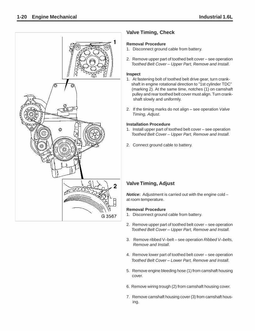
Inspect1. At fastening bolt of toothed belt drive gear, turn crank- shaft in engine rotational direction to ”1st cylinder TDC” (marking 2). At the same time, notches (1) on camshaft pulley and rear toothed belt cover must align. Turn crank- shaft slowly and uniformly.
2. If the timing marks do not align – see operation Valve Timing, Adjust.
Installation Procedure1. Install upper part of toothed belt cover – see operation Toothed Belt Cover – Upper Part, Remove and Install.
2. Connect ground cable to battery.
Valve Timing, Adjust
Notice: Adjustment is carried out with the engine cold –at room temperature.
Removal Procedure1. Disconnect ground cable from battery.
2. Remove upper part of toothed belt cover – see operation Toothed Belt Cover – Upper Part, Remove and Install.
3. Remove ribbed V–belt – see operation Ribbed V–belts, Remove and Install.
4. Remove lower part of toothed belt cover – see operation Toothed Belt Cover – Lower Part, Remove and Install.
5. Remove engine bleeding hose (1) from camshaft housing cover.
6. Remove wiring trough (2) from camshaft housing cover.
7. Remove camshaft housing cover (3) from camshaft hous- ing.

Industrial 1.6L Engine Mechanical 1-21
Adjust1. Screw fastening bolt for toothed belt drive gear into crankshaft and turn crankshaft in engine rotational di- rection until pointer (4) on toothed belt drive gear is flush with mark on oil pump housing.
2. Move toothed belt tension roller against spring force upward until bore holes align.
3. Fix toothed belt tension roller in place with suitable drift (5).
4. Mark running direction of toothed belt and remove toothed belt.

1-22 Engine Mechanical Industrial 1.6L
Adjust1. At hex of camshaft, turn camshaft sprocket (short way) to mark. Notch (2) on camshaft sprocket must align with mark (1) on rear toothed belt cover.
Installation Procedure1. Attach toothed belt – ensure that tension side (I) is taut. Note running direction of toothed belt.
2. Remove drift from toothed belt tension roller.
3. Adjust toothed belt tension – see operation Toothed Belt Tension, Adjust.
4. Install camshaft housing cover at camshaft housing – Tighten Tightening torque 8 Nm / 6 lb. ft.
5. Attach wiring trough to camshaft housing. Tighten Tightening torque 8 Nm / 6 lb. ft.
6. Attach engine bleeding hose to camshaft housing cover.
Removal Procedure1. Remove fastening bolt from toothed belt drive gear.
Installation Procedure1. Install lower part of toothed belt cover – see operation Toothed Belt Cover – Lower Part, Remove and Install.
2. Install ribbed V–belt – see operation Ribbed V–belt, Remove and Install.
3. Install upper part of toothed belt cover – see operation Toothed Belt Cover – Upper Part, Remove and Install.
4. Connect ground cable to battery.

Industrial 1.6L Engine Mechanical 1-23
Toothed Belt Tension, Check
Notice: Testing is performed with the engine cold – atroom temperature.
Removal Procedure1. Disconnect ground cable from battery.
2. Remove upper part of toothed belt cover – see operation Toothed Belt Cover – Upper Part, Remove and Install.
3. Remove ribbed V–belts – see operation Ribbed V–belts, Remove and Install.
4. Remove lower part of toothed belt cover – see operation Toothed Belt Cover – Lower Part, Remove and Install.
Adjust1. Screw fastening bolts of toothed belt drive gear into crank shaft and turn crankshaft in engine rotational direction until pointer (3) aligns with mark on oil pump housing. At the same time, notch (2) on camshaft pulley must be aligned with mark (1) on rear toothed belt cover.
Inspect1. The toothed belt tension is correctly adjusted when the pointer (4) of the movable part of the toothed belt tension roller aligns with notch (arrow).
2. If the toothed belt tension is not correctly adjusted – see operation Toothed Belt Tension, Adjust.
Removal Procedure1. Remove fastening bolt from toothed belt drive gear.
Installation Procedure1. Install lower part of toothed belt cover – see operation Toothed Belt Cover – Lower Part, Remove and Install.
2. Install ribbed V–belt – see operation Ribbed V–belt, Remove and Install.
3. Install upper part of toothed belt cover – see operation Toothed Belt Cover – Upper Part, Remove and Install.
4. Connect ground cable to battery.

1-24 Engine Mechanical Industrial 1.6L
Toothed Belt Tension, Adjust
Notice: Testing is performed with the engine cold – atroom temperature.
Removal Procedure1. Remove upper part of toothed belt cover – see operation Toothed Belt Cover – Upper Part, Remove and Install.
2. Remove ribbed V–belts – see operation Ribbed V–belts, Remove and Install.
3. Remove lower part of toothed belt cover – see operation Toothed Belt Cover – Lower Part, Remove and Install.
Adjust1. Screw fastening bolt for toothed belt drive gear into crank- shaft and turn crankshaft in engine rotational direction un- til pointer on toothed belt drive gear is flush with mark on oil pump housing. At the same time, notch on camshaft pulley must be flush with mark on rear toothed belt cover.
2. Release fastening bolts for coolant pump.
3. Tension toothed belt by turning coolant pump in direction of arrow (clockwise) with KM–421–A until pointer (1) is at right stop.

Industrial 1.6L Engine Mechanical 1-25
Adjust1. Turn crankshaft two revolutions (720°) in engine rota- tional direction, until timing marks align. Turn crankshaft slowly and uniformly and do not change position of cool- ant pump.
2. Reduce toothed belt tension by turning coolant pump in direction of arrow with KM–421–A until pointer (1) and notch (2) on toothed belt tension roller carrier plate align.
3. Set crankshaft another two revolutions (720°) in engine rotational direction to mark ”1st cylinder ignition TDC” and check adjustment of toothed belt tension roller. If marks do not align, repeat adjustment procedure.
Tighten Tighten coolant pump to cylinder block bolts to 8 Nm / 6 lb. ft.
Installation Procedure1. Remove fastening bolt from toothed belt drive gear and install toothed belt cover, lower part – see operation Toothed Belt Cover, Lower Part, Remove and Install.
2. Install ribbed V–belt – see operation Ribbed V–belt, Remove and Install.
3. Install upper part of toothed belt cover – see operation Toothed Belt Cover – Upper Part, Remove and Install.
4. Check cooling system for leaks – see operation in Sec- tion 3, Engine Cooling - Cooling System, Check for Leaks.
Repair InstructionsEngine Timing SideRibbed V–belt, Remove and Install
Removal Procedure1. Remove the fan guard. Refer to procedure Fan Guard Replacement.
2. Loosen the generator mounting bolts.
3. Move the generator inward to loosen the tension on the drive belt.
4. Slide the belt off the pulleys and over the fan blades.
5. Inspect the drive belt for:• Cracks• Glazing• Tears or cuts• Excessive wear

1-26 Engine Mechanical Industrial 1.6L
Installation Procedure
Tools Required:
••••• 6” Steel Rule
1. Slide the belt over the fan blades and route it over the pulleys.
2. Move the generator outward until the fan belt measures approximately 1/2 inch (13 mm) deflection.
Notice: Refer to Fastener Notice
3. While maintaining tension on the drive belt, tighten the generator mounting bolts.
Tighten Tighten the lower generator mounting bolt to 50 Nm / 37 lb. ft.
Tighten the upper generator mounting bolt to 25 Nm / 18 lb. ft.
4. Verify that the belt tension is correct with the ruler.
5. Install the fan guard. Refer to procedure Fan Guard Replacement.
Installation Procedure1. Install lower engine splash guard.
2. Install ribbed V–belt – see operation Ribbed V–belt, Remove and Install.
Toothed Belt Cover, Upper Part, Remove andInstall
Removal Procedure1. Remove fastening bolts (1) and remove upper part of toothed belt cover from rear toothed belt cover.
Installation Procedure1. Attach upper part of toothed belt cover to rear toothed belt cover. Tighten Tightening torque 4 Nm / 3 lb. ft.

Industrial 1.6L Engine Mechanical 1-27
Toothed Belt Cover, Lower Part, Removeand Install
Removal Procedure1. Remove upper part of toothed belt cover – see operation Toothed Belt Cover – Upper Part, Remove and Install.
2. Remove ribbed V–belts – see operation Ribbed V–belts, Remove and Install.
4. Lever closure plug (arrow) out of opening with screw driver. Lock drive disk or flywheel with KM–911 (1).
5. Detach increment disc (2) from crankshaft.
6. Remove fastening bolts (3) and remove lower part of toothed belt cover from rear toothed belt cover.
Installation Procedure1. Attach lower part of toothed belt cover to rear toothed belt cover. Tighten Tightening torque 4 Nm / 3 lb. ft.
2. Attach increment disc with new fastening bolt to crank- shaft. Tighten Tightening torque 95 Nm / 70 lb. ft. + 30° + 15°.
3. Remove Locking Tool KM–911 and insert new closure plug in aperture.
4. Install ribbed V–belt – see operation Ribbed V–belt, Remove and Install.
5. Install upper part of toothed belt cover – see operation Toothed Belt Cover – Upper Part, Remove and Install.

1-28 Engine Mechanical Industrial 1.6L
Toothed Belt, Remove and Install
Removal Procedure1. Remove upper part of toothed belt cover – see operation Toothed Belt Cover – Upper Part, Remove and Install.
2. Remove ribbed V–belts – see operation Ribbed V–belts, Remove and Install.
3. Remove lower part of toothed belt cover – see operation Toothed Belt Cover – Lower Part, Remove and Install.
Adjust1. Screw fastening bolt for toothed belt drive gear into crank shaft and turn crankshaft in engine rotational direction un til marks (2) on toothed belt drive gear and oil pump housing are flush. At the same time, notches (1) on camshaft pulley and rear toothed belt cover must be flush. Turn crankshaft slowly and smoothly.
Removal Procedure1. Move toothed belt tension roller upward against spring force until bore holes align. Fix toothed belt tension roller in place with suitable drift (3).
2. Mark running direction of the toothed belt for identifica- tion and remove toothed belt.
Installation Procedure1. Check toothed belt for wear – replace if necessary. Install toothed belt – ensure that tensioned side (I) is taut.
2. Observe timing marks. Adjust toothed belt tension – see operation Toothed Belt Tension, Adjust.
3. Remove fastening bolt from toothed belt drive gear and install toothed belt cover, lower part – see operation Toothed Belt Cover, Lower Part, Remove and Install.
4. Install ribbed V–belt – see operation Ribbed V–belt, Remove and Install.
5. Install upper part of toothed belt cover – see operation Toothed Belt Cover – Upper Part, Remove and Install.

Industrial 1.6L Engine Mechanical 1-29
Installation Procedure1. Install toothed belt tension roller – make sure that lug (1) of toothed belt tension roller base plate engages in groove (2) of oil pump.
2. Attach toothed belt tension roller to oil pump. Tighten Tightening torque 20 Nm / 15 lb. ft.
3. Install toothed belt – see operation Toothed Belt, Re- move and Install.
4. Install lower part of toothed belt cover – see operation Toothed Belt Cover – Lower Part, Remove and Install.
6. Install ribbed V–belt – see operation Ribbed V–belt, Remove and Install.
7. Install upper part of toothed belt cover – see operation Toothed Belt Cover – Upper Part, Remove and Install.
Toothed Belt Tension Roller, Remove andInstall
Removal Procedure1. Remove upper part of toothed belt cover – see operation Toothed Belt Cover – Upper Part, Remove and Install.
2. Remove ribbed V–belts – see operation Ribbed V–belts, Remove and Install.
3. Remove lower part of toothed belt cover – see operation Toothed Belt Cover – Lower Part, Remove and Install.
4. Remove toothed belt – see operation Toothed Belt, Re- move and Install.
3. Remove toothed belt tension roller (1) from oil pump.

1-30 Engine Mechanical Industrial 1.6L
Seal Ring in Front Camshaft Housing,Replace
Removal Procedure1. Remove upper part of toothed belt cover – see operation Toothed Belt Cover – Upper Part, Remove and Install.
2. Remove ribbed V–belts – see operation Ribbed V–belts, Remove and Install.
3. Remove lower part of toothed belt cover – see operation Toothed Belt Cover – Lower Part, Remove and Install.
4. Remove toothed belt – see operation Toothed Belt, Re- move and Install.
5. Remove engine vent hose from camshaft housing cover.
6. Detach wiring trough from camshaft housing cover.
7. Remove camshaft housing cover from camshaft housing.
8. Remove camshaft sprocket (1) from camshaft – counterhold with open–ended spanner on hex of cam shaft.
9. Edge out seal ring (2) with suitable tool.
Important: Do not damage sealing surfaces.
Installation Procedure1. Lightly coat sealing lip of seal ring with silicon grease (white). Press seal ring with KM–422 (3) in camshaft housing – use bolt and washer of camshaft pulley.

Industrial 1.6L Engine Mechanical 1-31
Removal Procedure1. Remove engine vent hose from camshaft housing cover.
2. Detach wiring trough from camshaft housing cover.
3. Remove camshaft housing cover from camshaft housing.
4. Remove camshaft sprocket (1) from camshaft – counterhold with open–ended spanner on hex of cam- shaft.
5. Edge out seal ring (2) with suitable tool.
Important: Do not damage sealing surfaces.
Installation Procedure1. Lightly coat sealing lip of seal ring with silicon grease (white).
2. Press seal ring with KM–422 (3) in camshaft housing – use bolt and washer of camshaft pulley.
3. Attach camshaft sprocket to camshaft – counterhold with open–ended spanner on hex of camshaft. Tighten Tightening torque 45 Nm / 33 lb. ft.
4. Install camshaft housing cover at camshaft housing. Tighten Tightening torque 8 Nm / 6 lb. ft.
5. Attach engine bleeding hose to camshaft housing cover.
6. Install toothed belt – see operation Toothed Belt, Re- move and Install.
7. Install lower part of toothed belt cover – see operation Toothed Belt Cover – Lower Part, Remove and Install.
8. Install ribbed V–belt – see operation Ribbed V–belt, Remove and Install.
9. Install upper part of toothed belt cover – see operation Toothed Belt Cover – Upper Part, Remove and Install.

1-32 Engine Mechanical Industrial 1.6L
Rear Toothed Belt Cover, Remove and Install
Removal Procedure1. Remove upper part of toothed belt cover – see operation Toothed Belt Cover – Upper Part, Remove and Install.
2. Remove ribbed V–belts – see operation Ribbed V–belts, Remove and Install.
3. Remove lower part of toothed belt cover – see operation Toothed Belt Cover – Lower Part, Remove and Install.
4. Remove toothed belt – see operation Toothed Belt, Re- move and Install.
5. Remove toothed belt tension roller – see operation Toothed Belt Tension Roller, Remove and Install.
6. Remove toothed belt drive gear (2) from crankshaft.

Industrial 1.6L Engine Mechanical 1-33
Removal Procedure1. Remove engine bleeding hose (1) from camshaft housing cover.
2. Remove camshaft housing cover (3) from camshaft hous- ing.
3. Remove camshaft sprocket – counterhold with open– ended spanner on hex of camshaft.
4. Unclip cable for crankshaft pulse pickup from rear toothed belt cover.
5. Remove rear toothed belt cover (arrows) from oil pump and camshaft housing.
Installation Procedure1. Attach rear toothed belt cover to oil pump and camshaft housing. Tighten Tightening torque 6 Nm / 4 lb. ft.
2. Clip cable for crankshaft pulse pickup to rear toothed belt cover – note cable routing.
3. Attach camshaft sprocket to camshaft – counterhold with open–ended spanner on hex of camshaft. Tighten Tightening torque 45 Nm / 33 lb. ft.
4. Install camshaft housing cover at camshaft housing. Tighten Tightening torque 8 Nm / 6 lb. ft.
5. Attach engine bleeding hose to camshaft housing cover.
6. Attach engine damping block support to cylinder block. Tighten Tightening torque 50 Nm / 37 lb. ft.
7. Slide toothed belt drive gear onto crankshaft journal – note installation position.
8. Install toothed belt tension roller – see operation Toothed Belt Tension Roller, Remove and Install.
9. Install toothed belt – see operation Toothed Belt, Re- move and Install.
10. Install lower part of toothed belt cover – see operation Toothed Belt Cover – Lower Part, Remove and Install.
11. Install ribbed V–belt – see operation Ribbed V–belt, Remove and Install.
12. Install upper part of toothed belt cover – see operation Toothed Belt Cover – Upper Part, Remove and Install.

1-34 Engine Mechanical Industrial 1.6L
Cylinder Head
Seal Ring in Rear Camshaft Housing,Replace
Removal Procedure1. Remove DIS ignition module – see operation DIS Igni- tion Module, Remove and Install.
2. Remove carrier plate (1) from camshaft housing.
Clean1. Clean sealing surfaces and remove gasket remnants.
Installation Procedure1. Coat seal ring (2) of carrier plate with silicone grease (white) and attach carrier plate to camshaft housing. Tighten Tightening torque 12 Nm / 9 lb. ft.
2. Install DIS ignition module – see operation DIS Ignition Module, Remove and Install.

Industrial 1.6L Engine Mechanical 1-35
Exhaust Manifold, Remove and Install
Removal Procedure1. Disconnect spark plug connectors (2) from 1st, 2nd and 3rd cylinder.
2. Remove heat shields (3) of 2nd and 3rd cylinders with KM–834–A from cylinder head.
3. Remove heat shield (4) from exhaust manifold.
4. Remove exhaust manifold (5) from cylinder head.
Clean1. Clean sealing surfaces and remove gasket remnants.
Installation Procedure1. Attach exhaust manifold with new gasket and new nuts to cylinder head. Tighten Tightening torque 22 Nm / 16 lb. ft.
2. Attach heat shield to exhaust manifold. Tighten Tightening torque 8 Nm / 6 lb. ft.
3. Coat heat shields with assembly paste (white) and in- stall in cylinder head with KM–834–A. Tighten Tightening torque 25 Nm / 18 lb. ft.
4. Connect spark plug connectors.
For version with hex bolts: Attach front exhaust pipe with new gasket and bolts coated with assembly paste (white) to exhaust manifold. Tighten Tightening torque 35 Nm / 26 lb. ft.
For version with hex nuts: Attach front exhaust pipe with new gasket and new nuts to exhaust manifold. Tighten Tightening torque 45 Nm / 33 lb. ft.
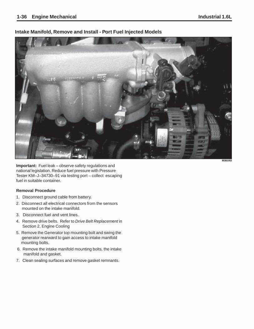
1-36 Engine Mechanical Industrial 1.6L
Important: Fuel leak – observe safety regulations andnational legislation. Reduce fuel pressure with PressureTester KM–J–34730–91 via testing port – collect escapingfuel in suitable container.
Removal Procedure
1. Disconnect ground cable from battery.
2. Disconnect all electrical connectors from the sensors mounted on the intake manifold.
3. Disconnect fuel and vent lines.
4. Remove drive belts. Refer to Drive Belt Replacement in Section 2, Engine Cooling
5. Remove the Generator top mounting bolt and swing the generator rearward to gain access to intake manifold mounting bolts.
6. Remove the intake manifold mounting bolts, the intake manifold and gasket.
7. Clean sealing surfaces and remove gasket remnants.
80361003
Intake Manifold, Remove and Install - Port Fuel Injected Models

Industrial 1.6L Engine Mechanical 1-37
Installation Procedure
Notice: Refer to Fastener Notice on page 1-2.
1. Install the intake manifold, a new gasket, and the intake manifold mounting bolts.
Tighten
Tighten the intake manifold bolts to 22 N•m (16 lb ft).2. Swing the generator forward into position and install the
top mounting bolt.
Tighten
Tighten the top mounting bolt to 20 N•m (15 lb ft).
Tighten the bottom mounting bolt and nut to 35 N•m (26 lb ft).
3. Install the drive belt. Refer to Drive Belt Replacement in Engine Cooling.
4. Connect the fuel and vent lines.
5. Connect all electrical connectors to the sensors mounted on the intake manifold.
6. Connect ground cable to the battery.
Tighten
Tighten the battery side terminal bolts (if applicable) to 12 N•m (106 lb in). Tighten the top terminal nuts (if applicable) to 18 N•m (13 lb ft).
80361003
Intake Manifold, Remove and Install - Port Fuel Injected Models (Continued)

1-38 Engine Mechanical Industrial 1.6L
Intake Manifold, Remove and Install - ThrottleBody Injected Models
Important: Fuel leak – observe safety regulations andnational legislation. Reduce fuel pressure with PressureTester KM–J–34730–91 via testing port – collect escapingfuel in suitable container.
Removal Procedure1. Disconnect ground cable from battery.
2. Open coolant drain bolt – collect escaping coolant.
3. Remove engine vent hoses (4) and (5) from camshaft housing cover.
4. Disconnect wiring harness plug (3) from intake air tem- perature sensor.
5. Disconnect wiring harness plug (1) from tank vent valve (2). Detach tank vent valve from air cleaner housing.
6. Remove ribbed V–belts – see operation Ribbed V–belts, Remove and Install.
7. Detach tank vent valve hose (6) from throttle body.
8. Detach coolant hoses (7) from throttle body and lay aside.

Industrial 1.6L Engine Mechanical 1-39
Removal Procedure9. Remove ground cable (2) from engine control unit.
10. Disconnect wiring harness plug (4) from oxygen sensor, (5) throttle body, (7) camshaft sensor and injectors.
11. Detach wiring harness bracket (1) from intake manifold and lay wiring harness aside.
12. Remove alternator support (3) from alternator and intake manifold. Release alternator from alternator shackle (6) and swing alternator rearward.
13. Detach coolant hose from intake manifold – place col- lecting basin underneath.
14. Detach fuel lines from fuel distributor pipe. Unclip fuel line from bracket and lay aside.
15. Remove intake manifold bolts.
16. Remove intake manifold, spacer, and gasket from cylinder head.
Clean Clean sealing surfaces and remove gasket remnants.
Installation Procedure1. Attach inlet manifold amd spacer with new seal to cylinder head. Tighten Tightening torque 22 Nm / 16 lb. ft.
2. Attach fuel line to fuel distributor pipe and clip in bracket.
3. Attach coolant hose to intake manifold.
4. Attach alternator to alternator shackle. Tighten Tightening torque 20 Nm / 15 lb. ft.
5. Attach alternator support to alternator and intake mani fold. Tighten Tightening torque 20 Nm / 15 lb. ft.
6. Route wiring harness and attach wiring harness bracket to intake manifold. Tighten Tightening torque 20 Nm / 15 lb. ft.
7. Connect wiring harness plug to injectors, camshaft sen- sor, throttle body and oxygen sensor.

1-40 Engine Mechanical Industrial 1.6L
Installation Procedure1. Attach coolant hoses to throttle body.
2. Install ribbed V–belt – see operation Ribbed V–belt, Remove and Install.
3. Attach engine vent hoses to camshaft housing cover.
4. Close coolant drain bolt.
5. Connect ground cable to battery.
Inspect1. Top up cooling system – see operations Cooling Sys- tem, Top Up and Bleed” and ”Cooling System, Check for Leaks.
Heat Shields, Remove and Install
Removal Procedure1. Remove fastening bolts for spark plug wiring trough.
2. Disconnect spark plug connectors and lay plug wires aside.
3. Remove heat shields from cylinder head with KM–834–A (1).
Installation Procedure1. Coat heat shields with assembly paste (white) and in- stall at cylinder head with KM–834–A. Tighten Tightening torque 25 Nm / 18 lb. ft.
2. Connect spark plug connectors.
3. Remove fastening bolts for ignition cable wiring trough.
Camshaft and Cam Follower, Remove andInstall (Cylinder Head Installed)
Removal Procedure1. Remove upper part of toothed belt cover – see operation Toothed Belt Cover – Upper Part, Remove and Install.
2. Remove ribbed V–belts – see operation Ribbed V–belts, Remove and Install.
3. Remove lower part of toothed belt cover – see operation Toothed Belt Cover – Lower Part, Remove and Install.

Industrial 1.6L Engine Mechanical 1-41
Important: Before dismantling the toothed belt – screwfastening bolt for toothed belt drive gear into crankshaft andmove crankshaft in engine rotational direction by 60°(dimension I) to before TDC mark.
Removal Procedure1. Move toothed belt tension roller upward against spring force until bore holes align. Fix toothed belt tension roller in place with suitable drift (1).
2. Remove toothed belt from camshaft sprocket.
3. Remove camshaft sprocket – see operation Seal Ring in Front Camshaft Housing, Replace.
4. Remove DIS ignition module – see operation DIS Igni- tion Module, Remove and Install.
5. Remove carrier plate from camshaft housing – see op- eration Seal Ring in Rear Camshaft Housing, Replace.
6. Remove pressure plate (1) from camshaft housing.
Important: Cover oil return bore holes in cylinder headduring assembly so thrust pieces cannot fall in.

1-42 Engine Mechanical Industrial 1.6L
Removal Procedure1. Attach Valve Lifter Depressor MKM–891 to camshaft housing.
2. Uniformly compress all cam followers.
3. Pull camshaft (1) out of camshaft housing.
4. Release valve lifter depressor and remove from camshaft housing.
5. Remove cam followers and thrust pieces – lay aside in installation position and note layout.
Inspect1. Check all parts for damage and wear and replace if nec essary. When replacing camshaft all cam followers must be replaced. Prior to installation ensure that crankshaft is 60° before TDC mark.
Installation Procedure1. Insert thrust pieces and cam followers – note installation position and allocation.
2. Attach valve lifter depressor onto camshaft housing and press down all cam followers uniformly.
3. Coat sliding surfaces with MoS2 lubricating paste (grey).
4. Insert camshaft in camshaft housing.
5. Install pressure plate on camshaft housing. Tighten Tightening torgue 8 Nm / 6 lb. ft.
Removal Procedure1. Release tension in valve lifter depressor and remove from camshaft housing.
Installation Procedure1. Attach carrier plate to camshaft housing – see operation Seal Ring in Rear Camshaft Housing, Replace.
2. Attach DIS ignition module – see operation DIS Ignition Module, Remove and Install.
3. Install camshaft sprocket – see operation Seal Ring in Front Camshaft Housing, Replace.
Important: Prior to installation of toothed belt, marks ontoothed belt drive gear and oil pump housing, as well asnotches on camshaft sprocket and rear toothed belt cover,must align – see operation Valve Timing, Adjust.

Industrial 1.6L Engine Mechanical 1-43
Installation Procedure1. Install toothed belt – see operation Toothed Belt, Re- move and Install.
2. Remove fastening bolt from toothed belt drive gear and install toothed belt cover, lower part – see operation Toothed Belt Cover, Lower Part, Remove and Install.
3. Install ribbed V–belt – see operation Ribbed V–belt, Remove and Install.
4. Install upper part of toothed belt cover – see operation Toothed Belt Cover – Upper Part, Remove and Install.
Hydraulic Valve Lifter, Replace (CylinderHead Installed)
Removal Procedure1. Detach engine vent hose from camshaft housing cover.
2. Detach wiring trough from camshaft housing cover.
3. Remove camshaft housing cover from camshaft housing.
Adjust1. At fastening bolt of toothed belt drive gear, turn crank- shaft in engine rotational direction until cam (1) of hy- draulic valve lifter to be replaced assumes a vertical posi- tion.
Removal Procedure1. Place KM–565–A (2) on camshaft housing and valve head and tension valve spring. Remove cam follower (3) from camshaft housing – note thrust piece.
2. Remove hydraulic valve lifter from camshaft housing.

1-44 Engine Mechanical Industrial 1.6L
Installation Procedure1. Insert hydraulic valve lifter (1) in camshaft housing.
2. Coat sliding surfaces of the rocker arm with MoS2 lubri- cating paste (grey) and insert in camshaft housing – note thrust piece.
Adjust1. Adjustment of the hydraulic valve lifter is no longer re- quired, as pre–tensioning has been taken into account in design.
Installation Procedure1. Release valve spring and remove KM–565–A.
2. Install camshaft housing cover at camshaft housing. Tighten Tightening torque 8 Nm / 6 lb. ft.
3. Attach wiring trough to camshaft housing cover. Tighten Tightening torque 8 Nm / 6 lb. ft.
4. Attach engine bleeding hose to camshaft housing cover.
Camshaft, Remove and Install (CylinderHead Removed)
Removal Procedure1. Remove DIS ignition module – see operation DIS Igni- tion Module, Remove and Install.
2. Remove carrier plate from camshaft housing – see op- eration Seal Ring in Rear Camshaft Housing, Replace.
3. Remove pressure plate (1) from camshaft housing.
4. Remove camshaft from camshaft housing.
5. Edge front seal ring out of camshaft housing.
Clean1. Clean sealing surfaces and remove gasket remnants.
Inspect1. Check camshaft housing for damage and wear – see operation Camshaft Housing for Plane Surface, Check. When replacing camshaft, always replace all cam follow- ers.

Industrial 1.6L Engine Mechanical 1-45
Installation Procedure1. Coat sliding surfaces of the camshaft with MoS2 lubri- cating paste (grey), insert camshaft in camshaft housing.
2. Install pressure plate on camshaft housing. Tighten Tightening torque: 8 Nm / 6 lb. ft.
3. Lightly coat sealing lip of front seal ring with silicon grease (white). Install new front seal ring with KM–422 in camshaft housing – use bolt and washer of camshaft pul- ley.
4. Attach carrier plate to camshaft housing – see operation Seal Ring in Rear Camshaft Housing, Replace.
5. Attach DIS ignition module – see operation DIS Ignition Module, Remove and Install.
Camshaft Housing, Replace
Removal Procedure1. Remove upper part of toothed belt cover – see operation Toothed Belt Cover – Upper Part, Remove and Install.
2. Remove ribbed V–belts – see operation Ribbed V–belts, Remove and Install.
3. Remove lower part of toothed belt cover – see operation Toothed Belt Cover – Lower Part, Remove and Install.
4. Remove toothed belt – see operation Toothed Belt, Re- move and Install.
5. Remove toothed belt tension roller – see operation Toothed Belt Tension Roller, Remove and Install.
6. Rear toothed belt cover – see operation Toothed Belt Cover – Rear, Remove and Install.
7. Detach or disconnect all wiring harness plugs, ground connections and hose connections from intake manifold see operation Intake Manifold, Remove and Install.
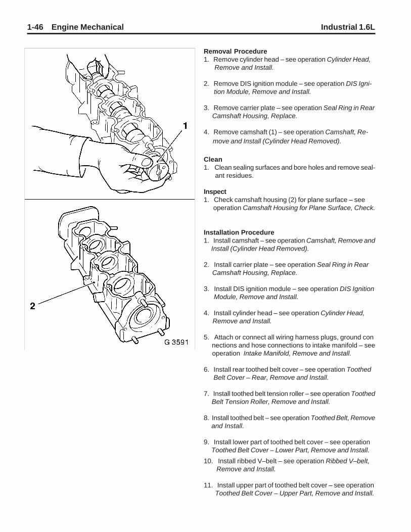
1-46 Engine Mechanical Industrial 1.6L
Removal Procedure1. Remove cylinder head – see operation Cylinder Head, Remove and Install.
2. Remove DIS ignition module – see operation DIS Igni- tion Module, Remove and Install.
3. Remove carrier plate – see operation Seal Ring in Rear Camshaft Housing, Replace.
4. Remove camshaft (1) – see operation Camshaft, Re- move and Install (Cylinder Head Removed).
Clean1. Clean sealing surfaces and bore holes and remove seal- ant residues.
Inspect1. Check camshaft housing (2) for plane surface – see operation Camshaft Housing for Plane Surface, Check.
Installation Procedure1. Install camshaft – see operation Camshaft, Remove and Install (Cylinder Head Removed).
2. Install carrier plate – see operation Seal Ring in Rear Camshaft Housing, Replace.
3. Install DIS ignition module – see operation DIS Ignition Module, Remove and Install.
4. Install cylinder head – see operation Cylinder Head, Remove and Install.
5. Attach or connect all wiring harness plugs, ground con nections and hose connections to intake manifold – see operation Intake Manifold, Remove and Install.
6. Install rear toothed belt cover – see operation Toothed Belt Cover – Rear, Remove and Install.
7. Install toothed belt tension roller – see operation Toothed Belt Tension Roller, Remove and Install.
8. Install toothed belt – see operation Toothed Belt, Remove and Install.
9. Install lower part of toothed belt cover – see operation Toothed Belt Cover – Lower Part, Remove and Install.
10. Install ribbed V–belt – see operation Ribbed V–belt, Remove and Install.
11. Install upper part of toothed belt cover – see operation Toothed Belt Cover – Upper Part, Remove and Install.

Industrial 1.6L Engine Mechanical 1-47
Camshaft Housing, Check for Plane Surface
Clean1. Clean sealing surfaces and remove gasket remnants.
Inspect1. Check sealing surfaces in length and width for deforma- tion and check for warping along the diagonals – use straight edge. If deformed or warped, replace camshaft housing.
Measure1. Height of camshaft housing (sealing surface to sealing surface). Dimension I: 66.5 mm
Cylinder Head, Remove and Install
Important: Remove cylinder head only with cold engine(room temperature).
Removal Procedure1. Detach battery ground cable.
2. Open coolant drain bolt – collect escaping coolant.
3. Remove engine bleeding hose (1) from camshaft housing cover.
4. Remove upper part of toothed belt cover – see operation Toothed Belt Cover – Upper Part, Remove and Install.
5. Remove ribbed V–belts – see operation Ribbed V–belts, Remove and Install.
6. Detach alternator support (3) from alternator and intake manifold. Release alternator from alternator shackle (2) and swing alternator rearward.

1-48 Engine Mechanical Industrial 1.6L
Removal Procedure1. Remove lower part of toothed belt cover – see operation Toothed Belt Cover – Lower Part, Remove and Install.
2. Screw fastening bolt for toothed belt drive gear into crank- shaft and move crankshaft in engine rotational direction by 90° (dimension I) to before TDC mark.
3. Detach or disconnect all wiring harness plugs, ground connections and hose connections from intake manifold – see operation Intake Manifold, Remove and Install.
4. Detach wiring harness plug (1) from DIS ignition module and expose wiring harness.
5. Detach wiring trough (2) from camshaft housing cover and lay aside.
6. Detach engine vent hose (3) from camshaft housing and engine vent flange and remove.
7. Remove coolant hose (6) from thermostat housing.
8. Detach ignition cable wiring trough from camshaft hous- ing cover.
9. Disconnect spark plug connectors.

Industrial 1.6L Engine Mechanical 1-49
Removal Procedure1. Move toothed belt tension roller upwards against spring force until bore holes align.
2. Fix toothed belt tension roller in place with suitable drift (2).
3. Mark running direction of the toothed belt for identifica- tion and remove toothed belt.
4. Remove toothed belt tension roller (4) from oil pump.
5. Remove toothed belt drive gear (3) from crankshaft.
6. Remove camshaft housing cover from camshaft housing.
7. Remove camshaft sprocket (1) – counterhold with open– ended spanner on hex of camshaft.

1-50 Engine Mechanical Industrial 1.6L
1. Remove rear part of toothed belt cover (arrow) from oil pump and camshaft housing.
2. Detach cylinder head bolts in sequence shown.
3. Remove camshaft housing from cylinder head.
4. Remove cam followers, thrust pieces and hydraulic valve lifter – note layout.
5. Remove cylinder head from cylinder block.
Clean1. Clean sealing surfaces, bore holes and thread of cylinder head bolts.
Inspect1. Check cylinder head and cylinder block for plane surface – see operations Cylinder Head, Check for Plane Sur- face and Cylinder Block, Check for Plane Surface.
Removal Procedure

Industrial 1.6L Engine Mechanical 1-51
Installation Procedure1. Install cylinder head gasket – mark ”OBEN/TOP” on top and towards timing side of engine.
2. Place cylinder head on cylinder block.
3. Insert hydraulic valve lifters, thrust pieces and cam fol- lowers with MoS2 paste (grey) – note allocation.
4. Apply a bead of surface sealant (green) to sealing sur- faces of cylinder head.
5. Place camshaft housing on cylinder head.
6. Tighten cylinder head bolts in order shown – use torque wrench and KM–470–B.
7. Attach cylinder head and camshaft housing with new cylinder head bolts to cylinder block. Tighten Tightening torque 25 Nm / 18 lb. ft. + 60° + 60° + 60°.
8. Attach rear toothed belt cover to oil pump and camshaft housing. Tighten Tightening torque 6 Nm / 4 lb. ft.
9. Attach camshaft sprocket to camshaft – counterhold with open–ended spanner on hex of camshaft. Tighten Tightening torque 45 Nm / 33 lb. ft.
10. Install camshaft housing cover at camshaft housing. Tighten Tightening torque 8 Nm / 6 lb. ft.
11. Attach engine damping block support to cylinder block. Tighten Tightening torque 50 Nm / 37 lb. ft.
12. Slide toothed belt drive gear onto crankshaft journal – note installation position.
13. Attach toothed belt tension roller to oil pump. Tighten Tightening torque 20 Nm / 15 lb. ft.
14. Install toothed belt – ensure that tensioned side (I) is taut.Notice: Note timing marks! – see operation Valve Timing,Adjust.
15. Adjust toothed belt tension – see operation Toothed Belt Tension, Adjust.

1-52 Engine Mechanical Industrial 1.6L
Installation Procedure1. Install lower part of toothed belt cover – see operation Toothed Belt Cover – Lower Part, Remove and Install.
2. Attach ignition cable wiring trough to camshaft housing Tighten Tightening torque 8 Nm / 6 lb. ft.
3. Connect spark plug connectors to spark plugs.
4. Attach coolant hose to thermostat housing.
5. Attach engine vent hose to camshaft housing and engine vent flange.
6. Connect wiring harness plug to DIS ignition module – note cable routing.
7. Attach engine bleeding hose to camshaft housing cover.
8. Attach or connect all wiring harness plugs, ground con- nections and hose connections to intake manifold – see operation Intake Manifold, Remove and Install.
9. For version with hex bolts: Attach front exhaust pipe with new gasket and bolts coated with assembly paste (white) to exhaust manifold. Tighten Tightening torque 35 Nm / 26 lb. ft.
10. For version with hex nuts: Attach front exhaust pipe with new gasket and new nuts to exhaust manifold. Tighten Tightening torque 45 Nm / 33 lb. ft.
11. Close coolant drain bolt.
12. Attach alternator to alternator shackle. Tighten Tightening torque 20 Nm / 15 lb. ft.
13. Attach alternator support to alternator and intake mani- fold. Tighten Tightening torque 20 Nm / 15 lb. ft.
14. Install ribbed V–belt – see operation Ribbed V–belt, Remove and Install.
15. Install upper part of toothed belt cover – see operation Toothed Belt Cover – Upper Part, Remove and Install.
16. Connect ground cable to battery.
Inspect1. Top up cooling system – see operations Cooling Sys- tem, Top Up and Bleed and Cooling System, Check for Leaks.

Industrial 1.6L Engine Mechanical 1-53
Cylinder Head, Check for Plane Surface
Clean1. Clean sealing surface and remove sealant remnants.
Inspect1. Check length and width of cylinder head sealing surfaces for deformation and diagonals for warpage – use straight edge.
Important: Resurfacing of the cylinder head is notpermitted.
Measure1. Height of cylinder head (sealing surface to sealing sur- face) Dimension I: 95.90 to 96.10 mm

1-54 Engine Mechanical Industrial 1.6L
Crank Drive, Cylinder BlockDrive Disc, Remove and Install
Removal Procedure1. Counterhold drive disc with KM–652 (1) and remove from crankshaft.
Installation Procedure1. Attach drive disc with new bolts to crankshaft. Counterhold drive disc with KM–652. Tighten Tightening torque 55 Nm / 41 lb. ft. + 30° + 15°.
Flywheel, Remove and Install
Removal Procedure1. Counterhold flywheel with KM–652 (1) and remove from crankshaft.
Installation Procedure1. Attach flywheel to crankshaft with new bolts. Lock flywheel with KM–652 (2). Tighten Tightening torque 35 Nm / 26 lb. ft. + 30° + 15°

Industrial 1.6L Engine Mechanical 1-55
Seal Ring – Rear Crankshaft, Replace
Removal Procedure1. Remove flywheel or drive disc – see operation Flywheel, Remove and Install or Drive Disc, Remove and Install.
2. Edge out seal ring (1) with suitable tool.
Important: Do not damage sealing surfaces.
Clean1. Clean sealing surfaces and remove gasket remnants.
Installation Procedure1. Coat sealing lip of new seal ring with silicon grease (white) and position with sealed side on Protective Sleeve KM–658–2 (2).
2. Connect protective sleeve with attached seal ring to crank- shaft journal and press in flush. Place Installer Sleeve KM–658–1 (3) on Protective Sleeve KM–658–2 (2) and drive in seal ring until it sits flush in housing.
3. Install flywheel or drive disc – see operation Flywheel, Remove and Install or Drive Disc, Remove and Install.
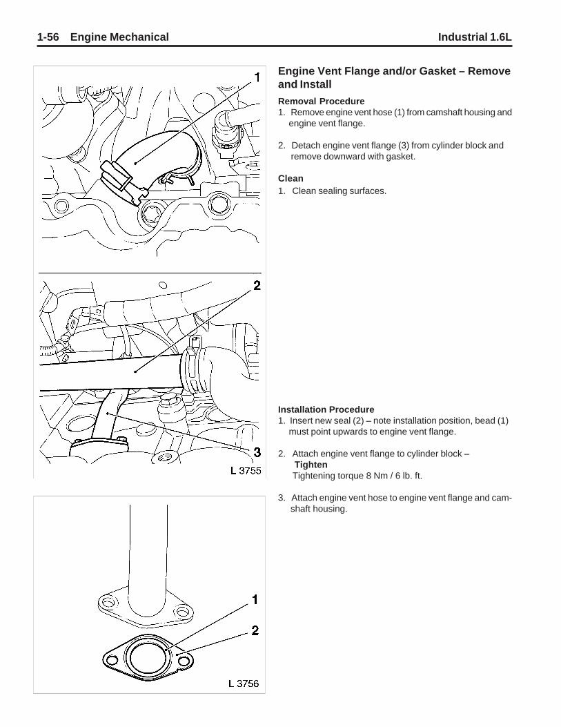
1-56 Engine Mechanical Industrial 1.6L
Removal Procedure1. Remove engine vent hose (1) from camshaft housing and engine vent flange.
2. Detach engine vent flange (3) from cylinder block and remove downward with gasket.
Clean1. Clean sealing surfaces.
Installation Procedure1. Insert new seal (2) – note installation position, bead (1) must point upwards to engine vent flange.
2. Attach engine vent flange to cylinder block – Tighten Tightening torque 8 Nm / 6 lb. ft.
3. Attach engine vent hose to engine vent flange and cam- shaft housing.
Engine Vent Flange and/or Gasket – Removeand Install

Industrial 1.6L Engine Mechanical 1-57
Piston with Con–rod, Remove and Install
Removal Procedure1. Remove oil pan – see operation Oil pan, Remove and Install.
2. Remove cylinder head – see operation Cylinder Head, Remove and Install.
3. Remove oil intake tube (1) from oil pump and cylinder block.
Important: Mark order of con–rod bearing caps.
4. Remove con–rod bearing cap from con–rod.
Important: The mating surfaces of the cod–rods and thecon–rod bearing caps form an individual fit and as a resultmust not be damaged or replaced under anycircumstances. Do not lay con–rods and con–rod bearingcaps on mating surfaces in order to avoid damage.
5. Remove combustion residue from upper part of cylinder bore.
6. Push piston with con–rod upwards from cylinder bore using a block of wood or using a soft material to drive each piston out of the block.

1-58 Engine Mechanical Industrial 1.6L
Important: Re-install the rod cap to the rod when thepiston is removed from the engine block. The matingsurfaces must be protected from damage.
Inspect1. Check all parts, clean and if necessary, replace. Re- place piston – see operation Piston, Replace.
AdjustBefore inserting con–rod journal of crankshaft, set to BDCposition and coat with engine oil.1. Adjust piston ring gaps: Oil scraper ring II: offset ring gaps of the steel band rings each 25 to 50 mm to the left or right of gap in intermedi- ate ring. Piston rings I: offset ring gaps by approx. 120°. Second piston ring with identification ”TOP” uppermost.
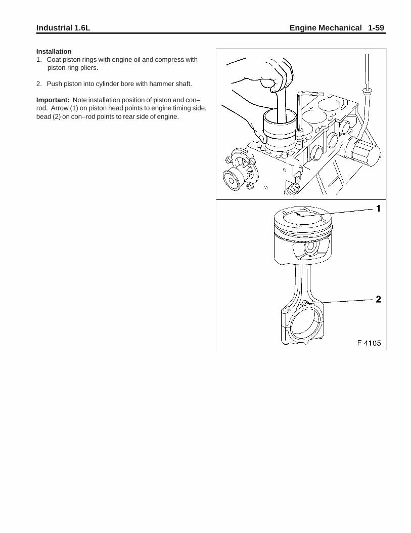
Industrial 1.6L Engine Mechanical 1-59
Installation1. Coat piston rings with engine oil and compress with piston ring pliers.
2. Push piston into cylinder bore with hammer shaft.
Important: Note installation position of piston and con–rod. Arrow (1) on piston head points to engine timing side,bead (2) on con–rod points to rear side of engine.

1-60 Engine Mechanical Industrial 1.6L
Installation ProcedureNote: Note sequence of con–rod bearing caps.1. Install con–rod bearing cap – bead (1) of con–rod bearing caps points to flywheel side.
2. Attach con–rod bearing cap to con–rod with new bolts. Torque Tightening torque 25 Nm / 18.5 lb. ft. + 30°.
3. Attach oil intake pipe (2) with new seal ring to oil pump. Torque Tightening torque 8 Nm / 6 lb. ft.
4. Attach oil intake manifold to cylinder block. Torque Tightening torque 8 Nm / 6 lb. ft.
5. Install cylinder head – see operation Cylinder Head, Remove and Install.
6. Install oil pan – see operation Oil Pan, Remove and Install.
Important: Clean up or recut threads with proper die beforereassembly and coat threads of new bolts with screw lock-ing compound (red). The installation time including the torquecheck is max. 10 min.
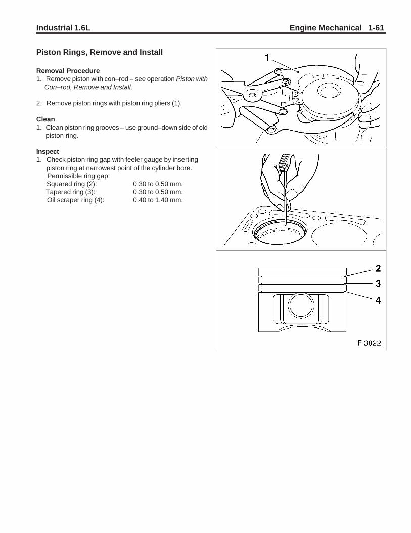
Industrial 1.6L Engine Mechanical 1-61
Piston Rings, Remove and Install
Removal Procedure1. Remove piston with con–rod – see operation Piston with Con–rod, Remove and Install.
2. Remove piston rings with piston ring pliers (1).
Clean1. Clean piston ring grooves – use ground–down side of old piston ring.
Inspect1. Check piston ring gap with feeler gauge by inserting piston ring at narrowest point of the cylinder bore. Permissible ring gap: Squared ring (2): 0.30 to 0.50 mm. Tapered ring (3): 0.30 to 0.50 mm. Oil scraper ring (4): 0.40 to 1.40 mm.

1-62 Engine Mechanical Industrial 1.6L
Inspect1. Check piston ring vertical play with feeler gauge in piston ring groove. Permissible vertical play: Squared ring (1): 0.02 to 0.04 mm Tapered ring (2): 0.04 to 0.06 mm Oil scraper ring (3): 0.01 to 0.03 mm.
Installation Procedure1. Insert piston rings with piston ring pliers and identifica- tion ”TOP” upwards in piston.
2. Piston ring positioning – piston rings (I) (rectangular and tapered compression ring) offset 120°. Oil scraper rings (II) – offset 25 to 50 mm to left and from right of gap in intermediate ring.
3. Install piston with con–rod – see operation Piston with Con–rod, Remove and Install.

Industrial 1.6L Engine Mechanical 1-63
Con–rod Bearing, Replace
Removal Procedure1. Remove oil pan – see operation Oil Pan, Remove and Install.
2. Remove oil intake tube (1) from oil pump and cylinder block.
Important: Mark order of con–rod bearing caps.
3. Remove con–rod bearing cap from con–rod.
Important: The mating surfaces of the cod–rods and thecon–rod bearing caps form an individual fit and as a resultmust not be damaged or replaced under anycircumstances. Do not lay con–rods and con–rod bearingcaps on mating surfaces in order to avoid damage. Presscon–rod bearing out of con–rod and con–rod bearing cap.
Clean1. Con–rod bearing journals and con–rod bearing caps.
Installation Procedure1. Insert new con–rod bearing shells with engine oil.
Important: Note sequence of con–rod bearing caps. Con–rod bearing caps – bead (1) of con–rod bearing caps pointsto flywheel side.
2. Attach con–rod bearing cap to con–rod with new bolts. Tighten Tightening torque 25 Nm / 18.5 lb. ft. + 30°.
3. Attach oil intake manifold to oil pump with new seal ring. Tighten Tightening torque 8 Nm / 6 lb. ft.
4. Attach oil intake manifold to cylinder block. Tighten Tightening torque 8 Nm / 6 lb. ft.
5. Apply a bead of adhesive sealing compound (black) to joints of oil pump and rear crankshaft bearing cap.
6. Install oil pan – see operation Oil Pan, Remove and Install.
Important: Clean up or recut threads with proper die beforereassembly and coat threads of new bolts with screw lock-ing compound (red). The installation time including the torquecheck is max. 10 min.

1-64 Engine Mechanical Industrial 1.6L
Con–rod Bearing Clearance, Check(Determine Bearing Clearance withPlastigage)
Removal Procedure1. Mark installation position (1) of con–rod bearing cap – remove con–rod bearing cap from con–rod.
Important: To prevent the strip from tearing whenremoving the con–rod bearing cap, remove grease from thecon–rod journal and lightly oil con–rod bearing shell. Donot turn the crankshaft.
Measure1. Route Plastigage (malleable plastic strip) over the entire width of the con–rod bearing journal.
Torque-Angle Method Con–rod bearing cap to con–rod. Tighten Tightening torque 25 Nm / 18 lb. ft. + 30°. The bolts can be reused for checking the con–rod bear- ing clearance.

Industrial 1.6L Engine Mechanical 1-65
Measure1. Remove con–rod bearing cap again. Compare width of flattened plastic thread (arrow) with measuring scale. Permissible con–rod bearing clearance: 0.019 to 0.071 mm.
Notice: When reading the value, do not confusemillimeters and inches on the measuring scale.
Installation Procedure1. Clean con–rod bearing journal and con–rod bearing shell and lubricate lightly.
2. Con–rod bearing cap to con–rod – note installation posi- tion of the con–rod bearing cap.
3. Attach con–rod bearing cap to con–rod with new bolts. Tighten Tightening torque 25 Nm / 18.5 lb. ft. + 30°.
Con–rod Bearing Clearance, Check(Determine Bearing Clearance withMicrometer and Inside Micrometer)
Notice: Con–rod and crankshaft are removed.
Installation Procedure1. Con–rod bearing cap with con–rod bearing shell to con– rod. Tighten Tightening torque 25 Nm / 18 lb. ft. + 30°. The bolts can be reused for checking the con–rod bear- ing clearance.
Formula for calculating the average con–rod bearing di- ameter: I + II + III
3
Example: I 42.738 mm II 42.732 mm III + 42.741 mm
128.211 mm / 3 = 42.737 mm
The average con–rod bearing diameter is 42.737 mm.

1-66 Engine Mechanical Industrial 1.6L
Measure1. The con–rod bearing journal diameter is measured with a micrometer at points I and II and then calculated. Formula for calculating the average con–rod bearing jour- nal diameter: I + II
2 Example: I 42.729 mm II + 42.725 mm
85.454 mm / 2 = 42.727 mm The average con–rod bearing journal diameter is 42.727 mm. The con–rod bearing clearance is calculated from the dif - ference in diameter between the con–rod bearing bore and the con–rod bearing journal. Example: Avg. con–rod bearing dia. 42.737 mm Avg. con–rod bearing journal dia. - 42.727 mm
0.010 mm
Permissible con–rod bearing clearance: 0.019 to 0.071 mm.
Piston, Replace
Notice: Removal of the piston pin is not permitted. If thepiston, the piston pin or the con–rod is defective, allabove–mentioned parts must be replaced.
Removal Procedure1. Remove piston with con–rod (1) – see operation Piston with Con–rod, Remove and Install.
Installation Procedure1. Coat con–rod eye and upper part of the con–rod shaft with thermocolor pencil. The green coloring turns black when the required assembly temperature is reached. The colored mark (arrow) is not permitted to discolor over the entire length, but only up to the start of the con–rod shaft. Heat new con–rod at upper con–rod eye with heater plate. Assembly temperature: 280 °C / 536 °F to max. 320 °C / 608 °F.
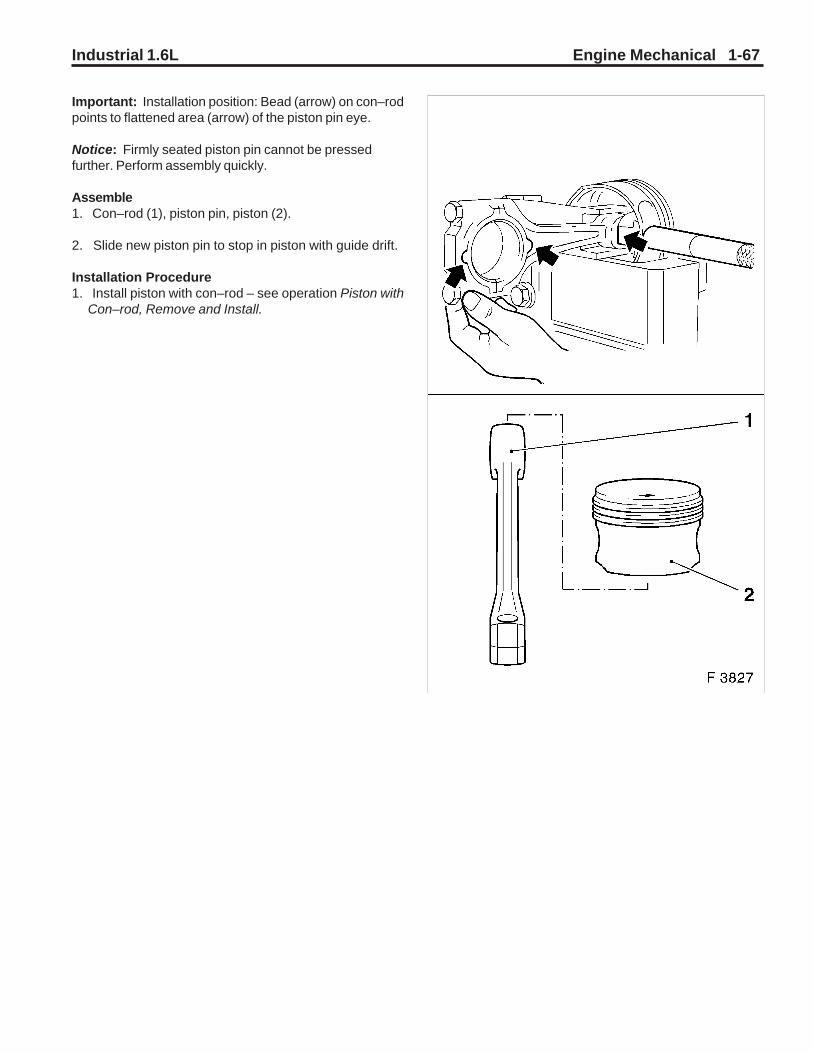
Industrial 1.6L Engine Mechanical 1-67
Important: Installation position: Bead (arrow) on con–rodpoints to flattened area (arrow) of the piston pin eye.
Notice: Firmly seated piston pin cannot be pressedfurther. Perform assembly quickly.
Assemble1. Con–rod (1), piston pin, piston (2).
2. Slide new piston pin to stop in piston with guide drift.
Installation Procedure1. Install piston with con–rod – see operation Piston with Con–rod, Remove and Install.

1-68 Engine Mechanical Industrial 1.6L
Crankshaft, Remove and Install
Removal Procedure1. Remove engine – see operation Engine, Remove and Install.
2. Mount engine with Adapter KM–412–10–A on Assembly Stands KM–412.
3. Remove oil pan – see operation Oil Pan, Remove and Install.
3. Remove oil pump – see operation Oil Pump, Remove and Install.
4. Lock flywheel or drive disc with KM–652 (1) and remove from crankshaft.
Important: Mark order of con–rod bearing caps. Removecon–rod bearing cap from conrod. The mating surfaces ofthe cod–rods and the con–rod bearing caps form anindividual fit and as a result must not be damaged orreplaced under any circumstances. Do not lay con–rodsand con–rod bearing caps on mating surfaces in order toavoid damage.

Industrial 1.6L Engine Mechanical 1-69
Removal Procedure
1. Identify sequence of crankshaft bearing caps.
2. Remove crankshaft bearing caps from cylinder block.
3. Remove crankshaft from cylinder block.
Clean
1. Clean all parts.
Inspect
1. Check crankshaft – see operation Crankshaft, Check.
Installation Procedure
1. Coat new bearing shells with engine oil and insert in cylinder block and bearing cap.
2. Insert crankshaft carefully in cylinder block. Seat of crank- shaft can be corrected by lightly tapping on crankshaft webs (1) with rubber hammer.
3. Apply a bead of adhesive sealing compound (black) to grooves of rear crankshaft bearing cap. Install crankshaft and con–rod bearing cap.
Note marks and installation position.
4. Crankshaft bearing cap to cylinder block.
Tighten
Tightening Torque 50 Nm / 37 lb. ft + 45° +15°.
5. Con–rod bearing cap to con–rod.
Tighten
Tightening torque 25 Nm / 18.5lb. ft. + 30°
6. Install crankshaft rear seal ring – see operation Seal Ring, Crankshaft, Rear Replace.
7. Lock flywheel or drive disc with KM–652.
8. Install flywheel with new bolts to crankshaft.
Tighten
Tightening torque 35 Nm / 26 lb. ft. + 30° + 15°.
9. Install drive disc with new bolts to crankshaft.
Tighten
Tightening torque 55 Nm / 41 lb. ft. + 30° + 15°.
10. Install oil pump – see operation Oil Pump, Remove and Install.
11. Remove engine from Overhaul Stand KM–412 and re- move Adapter KM–412–10 from engine. Install engine – see operation Engine, Remove and Install.
Important: Use new bolts. After assembly of bearing cap,press in adhesive sealing compound (black) from above againuntil adhesive sealing compound (black) escapes from thejoints.

1-70 Engine Mechanical Industrial 1.6L
Crankshaft, Check
Crankshaft End Clearance, Check
Measure
1. Attach Dial Gauge MKM–571–B with dial gauge bracket to one face of cylinder block and position probe of dial gauge on crankshaft.
2. Slide crankshaft in longitudinal direction. Permissible crankshaft longitudinal play: 0.100 to 0.202 mm.
Crankshaft Out–of–round, Check
Inspect
1. Remove crankshaft bearing cap.
2. Attach Dial Gauge MKM–571–B with dial gauge bracket to cylinder block.
3. Apply probe of the Dial Gauge MKM–571–B to crank shaft bearing journal.
4. Turn crankshaft uniformly. Max. perm. out–of–round: 0.03 mm.
5. Crankshaft bearing cap with new bolts to cylinder block. Tighten
Tightening torque 50 Nm / 37 lb. ft. + 45° + 15°.
Crankshaft Bearing Play, Check (DetermineBearing Play with Plastigage)
Inspect
1. Bearing play – crankshaft bearing cap removed.
Important: To prevent thread from tearing when removingcon–rod bearing cap, remove grease from con–rod journaland lightly oil con–rod bearing shell. Do not turncrankshaft.
Measure
1. With ”Plastigage” (deformable plastic thread).
2. Cut thread to bearing width and lay axially between crank- shaft journal and bearing shell (arrow). Install crankshaft bearing cap with torque –
Tighten
Tightening torque 50 Nm / 37 lb. ft. + 45° + 15°.
Notice: The bolts can be reused for checking crankshaftbearing clearance.

Industrial 1.6L Engine Mechanical 1-71
Removal Procedure
1. Remove crankshaft bearing cap.
Measure
1. Compare width of flattened plastic thread (arrow) with measuring scale.
”Plastigage” is available for various measuring ranges.
Perm. crankshaft bearing play: 0.015 to 0.041 mm.
Torque – Angle Method
1. Attach crankshaft bearing cap to cylinder block with new bolts.
Tighten
Tightening torque 50 Nm / 37 lb. ft. + 45° + 15°.
Crankshaft Bearing Clearance, Check(Determine Crankshaft Bearing ClearanceUsing External Micrometer and InsideMicrometer)
Notice: The crankshaft is removed.
Installation Procedure
1. Install crankshaft bearing cap with crankshaft bearing shell at cylinder block.
Tighten
Tightening torque 50 Nm / 37 lb. ft. + 45° + 15°. To check the crankshaft bearing play, bolt can be reused.
Measure
The average crankshaft bearing diameter is determined us-ing an inside micrometer at points I, II and III and then calcu-lated.
Formula for calculating the average crankshaft bearing diam-eter: I + II + III
3
Example:
I 54.972 mm
II 54.981 mm
III + 54.984 mm
164.937 mm / 3 = 54.979 mm
The average crankshaft bearing diameter is 54.979 mm.

1-72 Engine Mechanical Industrial 1.6L
Measure
1. The crankshaft journal diameter is measured with a micrometer at points I and II and then calculated.
Formula for calculating the average crankshaft bearing journal diameter: I + II
2
Example:
I 54.962 mm
II +54.964 mm
109.926 mm / 2 = 54.963 mm
The average crankshaft journal diameter is 54.963 mm.
The crankshaft clearance is calculated from the differ- ence in diameter between the crankshaft bearing bore and crankshaft journal.
Example:
Average crankshaft bearing dia. 54.979 mm
Average crankshaft journal dia. – 54.963 mm
0.016 mm
Permissible crankshaft bearing play: 0.015 to 0.041 mm.
Cylinder Block, Check for Plane Surface
Clean
1. Clean sealing surface and remove sealant remnants.
Inspect
1. Check sealing surfaces in length and width for deforma- tion and check for warping along the diagonals – use straight edge.

Industrial 1.6L Engine Mechanical 1-73
Oil Circuit
Oil Filter, Replace
Removal Procedure
1. Remove oil filter with KM–726–A (1) – place collecting basin underneath.
Installation Procedure
2. Coat seal ring of new oil filter lightly with engine oil and attach to cylinder block.
Tighten
Tightening torque 15 Nm / 11lb. ft.
Inspect
1. Check engine oil level and correct if necessary.
Bypass Valve, Replace
Removal Procedure
1. Remove oil filter – see operation Oil Filter, Replace.
2. Using tap (1) (M10 – 3rd speed) cut thread in shutter disc, screw in M10 bolt and remove bypass valve from seat.
Installation Procedure
1. Drive in bypass valve up to stop using drift (j approx. 15 mm).
2. Install oil filter – see operation Oil Filter, Replace.
Inspect
1. Check engine oil level and correct if necessary.
Front Seal Ring – Crankshaft, Replace
Removal Procedure
1. Remove upper part of toothed belt cover – see operation Toothed Belt Cover – Upper Part, Remove and Install.
2. Remove ribbed V–belts – see operation Ribbed V–belts, Remove and Install.
3. Remove lower part of toothed belt cover – see operation Toothed Belt Cover – Lower Part, Remove and Install.

1-74 Engine Mechanical Industrial 1.6L
Important: Before dismantling the toothed belt – screwfastening bolt for toothed belt drive gear into crankshaft andmove crankshaft in engine rotational direction by 60°(dimension I) to before TDC mark.
Removal Procedure
1. Remove toothed belt – see operation Toothed Belt, Re- move and Install.
2. Remove fastening bolt from toothed belt drive gear and pull toothed belt drive gear from crankshaft.
3. Edge out crankshaft seal ring (1) with suitable tool.
Important: Do not damage sealing surfaces.

Industrial 1.6L Engine Mechanical 1-75
Installation Procedure
1. Slide Protective Sleeve KM–417 (1) onto crankshaft jour- nal. Lightly coat sealing lip of the new seal ring with sili- con grease (white) and slide over the protective sleeve onto crankshaft journal.
Removal Procedure
1. Remove protective sleeve of KM–417 from crank journal.
Installation Procedure
1. Press seal ring with KM–417 (3) in oil pump – use bolt (2) and washer (4) of toothed belt drive gear.
2. Slide toothed belt drive gear onto crankshaft.
3. Install toothed belt – see operation Toothed Belt, Re- move and Install.
5. Install lower part of toothed belt cover – see operation Toothed Belt Cover – Lower Part, Remove and Install.
6. Install ribbed V–belt – see operation Ribbed V–belt, Remove and Install.
7. Install upper part of toothed belt cover – see operation Toothed Belt Cover – Upper Part, Remove and Install.

1-76 Engine Mechanical Industrial 1.6L
Oil Pan, Remove and Install
Removal Procedure
1. Open oil drain plug – place collecting basin underneath.
2. Remove oil pan from cylinder block and oil pump.
Clean
1. Clean sealing surfaces and remove gasket remnants.
Installation Procedure
1. Apply a bead of adhesive sealing compound (black) to joints of oil pump (shown bye the position of the arrows in the illustration to the left) and rear crankshaft bearing cap.
2. Install oil pan with new gasket (shown by the arrow in the illustration on the lower left) to oil pump and cylinder block. Attach oil drain plug to oil pan with new seal ring.
Tighten
Tightening torque 55 Nm / 40.6 lb. ft.
Important:
Installation sequence:
1. Tighten all bolts loosely.
2. Tighten bolts on cylinder block and oil pump.
Tighten
Tightening torque 10 Nm / 7.5 lb. ft.1).
3. Recut thread before reuse and insert bolts with screw locking compound (red). The installation time including the torque check is max. 10 min.
For version with hex bolts.
Tighten
Tightening torque 35 Nm / 26 lb. ft.1).
For version with hex nuts.
Tighten
Tightening torque 45 Nm / 33 lb. ft.2).
4. Fill engine oil up to ”MAX” at dipstick.
1) Insert bolts with mounting paste (white).
2) Use new nut(s).

Industrial 1.6L Engine Mechanical 1-77
5. Remove toothed belt – see operation Toothed Belt, Re- move and Install.
6. Remove toothed belt tension roller – see operation Toothed Belt Tension Roller, Remove and Install.
7. Remove rear toothed belt cover – see operation Toothed Belt Cover – Rear, Remove and Install.
8. Remove oil intake tube (1) from oil pump and cylinder block.
9. Disconnect wiring harness plug (2) from oil pressure switch.
10. Detach oil pump (4) from cylinder block.
11. Edge seal ring (5) out of oil pump.
Clean
1. Clean sealing surfaces and remove gasket remnants.
Oil Pump, Remove and Install
Important: Prior to removing toothed belt – set crankshaftto approx. 60° (dimension I) before TDC mark.
Removal Procedure
1. Remove oil pan – see operation Oil Pan, Remove and Install.
2. Remove upper part of toothed belt cover – see operation Toothed Belt Cover – Upper Part, Remove and Install.
3. Remove ribbed V–belts – see operation Ribbed V–belts, Remove and Install.
4. Remove lower part of toothed belt cover – see operation Toothed Belt Cover – Lower Part, Remove and Install.

1-78 Engine Mechanical Industrial 1.6L
Installation Procedure
1. Attach oil pump with new seal (1) to cylinder block.
Tighten
Tightening torque 10 Nm / 7 lb. ft.
2. Slide Protective Sleeve KM–417 onto crankshaft journal.
3. Lightly coat sealing lip of the new seal ring with silicon grease (white) and slide over the protective sleeve onto crankshaft journal.
Removal Procedure
1. Remove protective sleeve from crankshaft journal.
Installation Procedure
1. Press seal ring with KM–417 (3) in oil pump – use bolt (2) and washer (4) of toothed belt drive gear.
2. Connect wiring harness plug to oil pressure switch.
3. Attach oil intake manifold to oil pump with new seal ring Tighten
Tightening torque 8 Nm / 6 lb. ft.1).
4. Attach oil intake manifold to cylinder block.
Tighten
Tightening torque 8 Nm / 6 lb. ft.
5. Install rear toothed belt cover – see operation Toothed Belt Cover – Rear, Remove and Install.
6. Install toothed belt tension roller – see operation Toothed Belt Tension Roller, Remove and Install.
7. Install toothed belt – see operation Toothed Belt, Re- move and Install.
8. Install lower part of toothed belt cover – see operation Toothed Belt Cover – Lower Part, Remove and Install.
9. Install ribbed V–belt – see operation Ribbed V–belt, Remove and Install.
10. Install upper part of toothed belt cover – see operation Toothed Belt Cover – Upper Part, Remove and Install.
11. Install oil pan – see operation Oil Pan, Remove and Install.
1) Recut thread before reuse and insert bolts with screwlocking compound (red). The installation time including thetorque check is max. 10 min.

Industrial 1.6L Engine Mechanical 1-79
Oil Pump, Check
Removal Procedure
1. Remove oil pan – see operation Oil Pan, Remove and Install.
2. Remove upper part of toothed belt cover – see operation Toothed Belt Cover – Upper Part, Remove and Install.
3. Remove ribbed V–belts – see operation Ribbed V–belts, Remove and Install.
4. Remove lower part of toothed belt cover – see operation Toothed Belt Cover – Lower Part, Remove and Install.
5. Remove toothed belt – see operation Toothed Belt, Re- move and Install.
6. Remove toothed belt tension roller – see operation Toothed Belt Tension Roller, Remove and Install.
7. Rear toothed belt cover – see operation Toothed Belt Cover – Rear, Remove and Install.
8. Remove oil pump – see operation Oil Pump, Remove and Install.
9. Remove safety valve (1) and oil pump cover (2) from oil pump.
Inspect
1. Check gap of gear pair with feeler gauge (4) and straight edge (3). Dimension – 0.08 to 0.15 mm.
2. Check oil pump, oil pump cover and safety valve for signs of wear.

1-80 Engine Mechanical Industrial 1.6L
Installation Procedure
1. Oil pump cover to oil pump.
Tighten
Tightening torque 6 Nm / 4 lb. ft.
2. Install safety valve with new seal ring in oil pump.
Tighten
Tightening torque 50 Nm / 37 lb. ft.
3. Install oil pump – see operation Oil Pump, Remove and Install.
4. Install rear toothed belt cover – see operation Toothed Belt Cover – Rear, Remove and Install.
5. Install toothed belt tension roller – see operation Toothed Belt Tension Roller, Remove and Install.
6. Install toothed belt – see operation Toothed Belt, Re- move and Install.
7. Install lower part of toothed belt cover – see operation Toothed Belt Cover – Lower Part, Remove and Install.
8. Install ribbed V–belt – see operation Ribbed V–belt, Remove and Install.
9. Install upper part of toothed belt cover – see operation Toothed Belt Cover – Upper Part, Remove and Install.
10. Install oil pan – see operation Oil Pan, Remove and Install.

Industrial 1.6L Engine Mechanical 1-81
Oil Intake Pipe, Remove and Install
Removal Procedure
1. Remove oil pan – see operation Oil Pan, Remove and Install.
2. Remove oil intake tube (1) from oil pump and cylinder block.
Installation Procedure
1. Attach oil intake manifold to oil pump with new seal ring.
Tighten
Tightening torque 8 Nm / 6 lb. ft.1).
2. Attach oil intake manifold to cylinder block.
Tighten
Tightening torque 8 Nm / 6 lb. ft.
3. Install oil pan – see operation Oil Pan, Remove and Install.
1) Recut thread before reuse and insert bolts with screwlocking compound (red). The installation time including thetorque check is max. 10 min.
Safety Valve, Remove and Install
Removal Procedure
1. Remove closure plug (1) from oil pump.
2. Remove seal ring, spring, piston from oil pump.
Installation Procedure
1. Insert piston (2) – ensure installation position is correct.
2. Insert spring (3) in oil pump.
3. Attach closure plug (5) to oil pump with new seal ring (4).
Tighten
Tightening torque 50 Nm / 37 lb. ft.

1-82 Engine Mechanical Industrial 1.6L
Oil Baffle Plate, Remove and Install
Removal Procedure
1. Remove oil pan – see operation Oil Pan, Remove and Install.
2. Remove oil baffle plate (1).
Installation Procedure
1. Attach oil baffle plate to oil pan.
Tighten
Tightening torque 8 Nm / 6 lb. ft.
2. Install oil pan – see operation Oil Pan, Remove and Install.
Oil Pressure Switch, Remove and Install
Removal Procedure
1. Detach wiring harness plug (1) from oil pressure switch.
2. Disconnect oil pressure switch (2) from oil pump – place collection pan underneath.
Installation Procedure
1. Attach oil pressure switch to oil pump with new seal ring.
Tighten
Tightening torque 30 Nm / 22 lb. ft.
2. Connect wiring harness plug to oil pressure switch.
Inspect
1. Check engine oil level and correct if necessary.

Industrial 1.6L Engine Mechanical 1-83
Oil Dipstick Guide Tube, Remove and Install
Removal Procedure
1. Withdraw oil dipstick guide tube (1) from cylinder block.
Installation Procedure
1. Push new seal ring (2) onto oil dipstick guide tube and lightly coat with engine oil.
2. Insert oil dipstick guide tube up to stop in cylinder block.
Crankshaft Position Sensor, Remove andInstall
Refer to operation Crankshaft Position Sensor, Removeand Install in Section 3, Engine Electrical.
Reference Gap Between Crankshaft PositionSensor and Increment Disc, Check
Refer to operation Reference Gap Between CrankshaftPosition Sensor and Increment Disc, Check in Section 3,Engine Electrical.

1-84 Engine Mechanical Industrial 1.6L
Coolant Thermostat, Remove and Install
Refer to operation Coolant Thermostat, Remove and Installin Section 2, Engine Cooling.
Fuel Pressure, Check
Important: Fuel escapes. Observe safety regulations andnational legislation.
Installation Procedure
1. Connect Pressure Gauge KM–J–34730–91 (1) to test connection (2).
2. Start engine and bleed pressure gauge – idle speed. Collect escaping fuel in a suitable container.
Inspect
1. Check fuel pressure.
2. Start engine and allow to run at idle speed. Nominal value – see relevant Checking Procedures.
Removal Procedure
1. Detach pressure gauge from test connection.
Coolant Pump, Remove and Install
Refer to operation Coolant Pump, Remove and Install inSection 2, Engine Cooling.
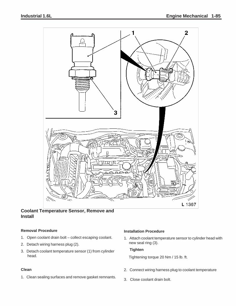
Industrial 1.6L Engine Mechanical 1-85
Coolant Temperature Sensor, Remove andInstall
Removal Procedure
1. Open coolant drain bolt – collect escaping coolant.
2. Detach wiring harness plug (2).
3. Detach coolant temperature sensor (1) from cylinder head.
Clean
1. Clean sealing surfaces and remove gasket remnants.
Installation Procedure
1. Attach coolant temperature sensor to cylinder head with new seal ring (3).
Tighten
Tightening torque 20 Nm / 15 lb. ft.
2. Connect wiring harness plug to coolant temperature
3. Close coolant drain bolt.
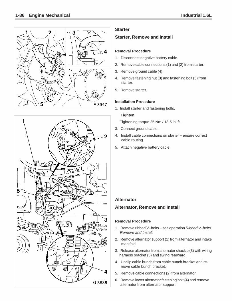
1-86 Engine Mechanical Industrial 1.6L
Starter
Starter, Remove and Install
Removal Procedure
1. Disconnect negative battery cable.
2. Remove cable connections (1) and (2) from starter.
3. Remove ground cable (4).
4. Remove fastening nut (3) and fastening bolt (5) from starter.
5. Remove starter.
Installation Procedure
1. Install starter and fastening bolts.
Tighten
Tightening torque 25 Nm / 18.5 lb. ft.
3. Connect ground cable.
4. Install cable connections on starter – ensure correct cable routing.
5. Attach negative battery cable.
Alternator
Alternator, Remove and Install
Removal Procedure
1. Remove ribbed V–belts – see operation Ribbed V–belts, Remove and Install.
2. Remove alternator support (1) from alternator and intake manifold.
3. Release alternator from alternator shackle (3) with wiring harness bracket (5) and swing rearward.
4. Unclip cable bunch from cable bunch bracket and re- move cable bunch bracket.
5. Remove cable connections (2) from alternator.
6. Remove lower alternator fastening bolt (4) and remove alternator from alternator support.

Industrial 1.6L Engine Mechanical 1-87
Installation Procedure
1. Position alternator in alternator support and hand–tighten lower alternator fastening bolt.
2. Attach cable connections to alternator.
3. Attach alternator and wiring harness bracket to alterna- tor shackle.
Tighten
Tightening torque 20 Nm/ 15 lb. ft.
4. Clip cable bundle to cable bundle bracket.
5. Attach alternator support to alternator and intake mani- fold.
Tighten
Tightening torque 20 Nm / 15 lb. ft.
6. Install lower alternator fastening bolt.
Tighten
Tightening torque 35 Nm/ 26 lb. ft.
7. Install ribbed V–belt – see operation Ribbed V–belt, Remove and Install.

1-88 Engine Mechanical Industrial 1.6L
Special Tools and Equipment
KM–135 Adapter
To measure engine oil pressure in conjunction with
KM–498–B
KM–194–E Spark Plug Key
To remove and install spark plugs, A/F 16 mm
KM–301 Gauge Bar
To check piston projection
KM–340–1–F Cutter Set
To mill, rework valve seats
KM–348 Spring Compressor
To compress valve springs, cylinder head removed

Industrial 1.6L Engine Mechanical 1-89
KM–352 InstallerTo install valve stem sealing
KM–412 Engine Overhaul StandTo hold removed engine
KM–412–10 AdapterTo hold engine in conjunction with KM–412
KM–417 Assembly SleevesTo press crankshaft seal ring into oil pump housing
Special Tools and Equipment (Continued)
KM–419 Distance GaugeTo check valve stem projection
KM–421–A Adjusting WrenchTo adjust toothed belt tension

1-90 Engine Mechanical Industrial 1.6L
KM–422 InstallerTo press seal ring in camshaft housing
KM–427 Remover / InstallerTo install guide pins into engine block
KM–470–B Angular Torque WrenchTo tighten cylinder head bolts
KM–471 AdapterTo check pressurized cooling system in conjunction withcooling system tester
Special Tools and Equipment (Continued)
KM–498–B Oil pressure gaugeTo check engine oil pressure in conjunction withKM–135
KM–565–A Remover / InstallerTo remove and install rocker arms and valve playcompensator

Industrial 1.6L Engine Mechanical 1-91
MKM–571–B Dial GaugeTo measure piston projection
MKM–588–A Pressure GaugeTo check fuel pressure
MKM–596–A Temperature GaugeTo measure oil temperature, exhaust gas special test (Ger-man AU)
MKM–604–D Torx Bit and Socket SetTo remove/install Torx bolts
SpecialTools and Equipment (Continued)
KM–609 Electronic Kit IDiagnosis of electric and electronic systems
MKM–610 Torque Wrench, 1/2”Range 30 – 130 Nm / 22 – 96 lb. ft.

1-92 Engine Mechanical Industrial 1.6L
MKM–611 Torque Wrench, 3/8”Range 10 – 60 Nm / 7 – 44 lb. ft.
KM–634 Remover / InstallerTo remove/install piston pin
KM–652 Flywheel HolderTo lock flywheel/drive disc
Special Tools and Equipment (Continued)
KM–658 InstallerTo install crankshaft rear seal ring
KM–664 Reamer Set 7 mmValve guide ream (j 7 mm)
MKM–667 Pressure and Vacuum PumpTo check for leaks in vacuum unit
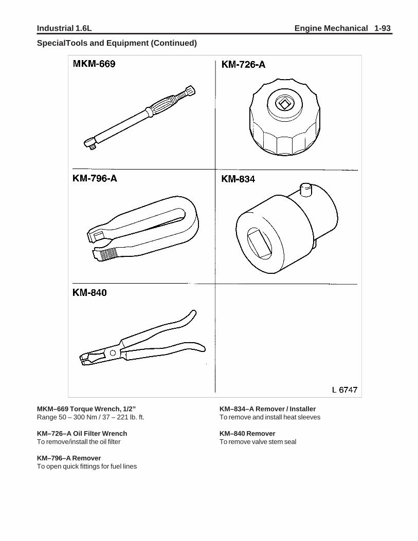
Industrial 1.6L Engine Mechanical 1-93
MKM–669 Torque Wrench, 1/2”Range 50 – 300 Nm / 37 – 221 lb. ft.
KM–726–A Oil Filter WrenchTo remove/install the oil filter
KM–796–A RemoverTo open quick fittings for fuel lines
SpecialTools and Equipment (Continued)
KM–834–A Remover / InstallerTo remove and install heat sleeves
KM–840 RemoverTo remove valve stem seal

1-94 Engine Mechanical Industrial 1.6L
MKM–889 Automatic Valve Spring LeverTo remove/install the valve stem seals (cylinder head installed)
MKM–891 Valve Lifter DepressorTo remove/install camshaft (cylinder head installed)
KM–904 Base FrameTo remove and install various vehicle componentswith additional adapters
Special Tools and Equipment (Continued)
KM–911 Flywheel HolderTo lock flywheel/drive disc
KM–2355 Socket Wrench T55To loosen/tighten cylinder head bolts

Industrial 1.6L Engine Mechanical 1-95
KM–6000 Centering ToolTo remove and install front axle in conjunction withKM–904
KM–6001–A Engine MountTo align engine to body in conjunction with KM–6173
KM–6173 Engine MountTo support engine on front axle body in conjunction with KM–6001–A
Special Tools and Equipment (Continued)
KM–6179 Remover / InstallerTo remove and install oxygen sensor
KM–J–34730–91 Pressure TesterTo check fuel pressure

Industrial 1.6L Engine Cooling 2-1
Fastener Notice ....................................................... 2-2Specifications ......................................................... 2-3Fastener Tightening Specifications ........................... 2-3Engine Cooling System Specifications...................... 2-3Diagnostic Information and Procedures ............... 2-4Engine Overheating .................................................. 2-4Loss of Coolant......................................................... 2-5Thermostat Diagnosis ............................................... 2-5Engine Fails To Reach Normal Operating Temp........ 2-6Coolant Concentration Testing .................................. 2-7Cooling System Leak Testing .................................... 2-8Repair Instructions ................................................. 2-9Draining and Filling Cooling System ......................... 2-9Cooling System Flushing .......................................... 2-9Cooling System Scale Removal ................................ 2-9Radiator Hose Replacement ................................... 2-10Fuel Injection Coolant Hose Replacement .............. 2-10
Coolant Pipe and/or Hose Replacement ................. 2-11Drive Belt Replacement .......................................... 2-12Cooling Fan Replacement ...................................... 2-12Fan Shroud Replacement ....................................... 2-13Fan Guard Replacement ........................................ 2-14Coolant Thermostat and/or Housing Replacement . 2-15Water Pump Replacement ...................................... 2-16Drain Cock Replacement ........................................ 2-18Radiator Replacement ............................................ 2-18Description and Operation ................................... 2-19Cooling System Description .................................... 2-19Radiator Assembly Description ............................... 2-19Pressure Cap Description ....................................... 2-20Water Pump Description ......................................... 2-21Thermostat Description .......................................... 2-21Special Tools and Equipment .............................. 2-21
Section 2Engine Cooling

2-2 Engine Cooling Industrial 1.6L
Fastener NoticeNOTICE: Always use the correct fastener in the proper location. When you replace a fastener, use ONLY the exact partnumber of that application.
UNLESS OTHERWISE SPECIFIED, Do Not use supplemental coatings (paints, greases or other corrosion inhibitors) onthreaded fasteners or fastener joint interfaces. Generally, such coating adversely affect the fastener torque and the jointclamping force, and may damage the fastener.
When you install fasteners, use the correct tightening sequence and specifications.
Following these instructions can help you avoid damage to parts and systems.

Industrial 1.6L Engine Cooling 2-3
Engine Cooling System Specifications
Application Metric English1.6L (w/o radiator) 3.3 liters 3.5 quarts1.6L (w/radiator) 9.5 liters 10 quarts
Engine Cooling - 1.6LSpecifications
Fastener Tightening Specifications
Application N•m lb ft lb inCoolant Temperature Sensor 20 14Drain Cock to Radiator 18 13Fan Blade to Pulley Bolts 15-18 10-13Fan Guard Mounting Bolts 16-20 12-15 12-15Fan Housing Mounting Bolts 16-20 12-15All Hose Clamps 2.5 22Radiator Mounting Bracket Bolts 25 18Water Pump to Engine Block Mounting Bolts 8 6Thermostat Housing to Cylinder Head Bolts 10 7Generator Upper Bracket Mounting Bolt 20 15Generator Lower Bracket Mounting Bolt 35 26

2-4 Engine Cooling Industrial 1.6L
Diagnostic Information and Procedures
Engine Overheating
Step Action Value(s) Yes No1 Check the coolant level.
Is the coolant level low?—
Go to Step 2 Go to Step 3
2 Add coolant to the systemDoes the engine still overheat?
—Go to Step 3 System OK
3 Pressure test the system and check for visual leaks.Are there any external leaks in the system?
— Go to Loss ofCoolant. Go to Step 4
4 Check the condition of the drive belt.Is the drive belt loose or unserviceable?
— Adjust or replacethe drive belt. Go to Step 5
5 Check the hoses.Have the hoses collapsed?
—Go to Step 6 Go to Step 7
6 Replace the hoses. Refer to Radiator Hose Replacement.Does the engine still overheat?
—Go to Step 7 System OK
7 Check the temperature level of the thermostat.Is the temperature level high?
—Go to Step 8 Go to Step 9
8 Replace the thermostat. Refer to ThermostatReplacement. Does the engine still overheat?
—Go to Step 9 System OK
9 Check the radiator.Is the radiator clogged?
— Go to CoolingSystem Flushing Go to Step 10
10 Check the engine block.Is the engine block clogged?
— Go to CoolingSystem Flushing Go to Step 11
11 Check for bubbles in the coolant.Are there bubbles in the coolant?
—Go to Step 12 Go to Step 13
12 Perform a Compression Test. Refer to Engine MechanicalWere results OK.
—Go to Step 13
Go to EngineMechanical
13 Check the water pump.Does coolant flow?
—Go to Step 15 Go to Step 14
14 Replace the water pump. Refer to Water PumpReplacement.Does the engine still overheat?
—
Go to Step 15 System OK
15 Check the radiator fan.Is the radiator fan operating normally?
—Go to Step 16 Go to Step 17
16 Check for any of the following conditions that maycontribute to the engine overheating:
• An overloaded condition• Excess engine oil• Blocked air flow through the radiator• Extreme air temperatures
Does the engine still overheat?
— —
System OK
17 Replace the radiator fan. Refer to Cooling FanReplacement.Does the engine still overheat?
— —
System OK

Industrial 1.6L Engine Cooling 2-5.
Loss of Coolant
Thermostat Diagnosis
Use the following procedure to check for engine overheating, boiling or poor engine cooling:Hang the thermostat on a hook in order to perform an operational check of the thermostat. Hang the thermostat in a33 percent glycol solution at 12°C (10°F) below the temperature indicated on the valve. The valve will close when you submerge the valve and agitate the coolant.Use the following procedure to check for engine overheating, boiling or poor engine cooling:
1. Relieve the pressure and carefully remove the radiator cap.2. Rub a 96.6°C (206°F) temperature stick on the thermostat housing.3. Warm up the engine at a fast idle. Watch for coolant flow before the mark begins to melt.
• If the coolant does not flow, install a new thermostat. Recheck the system in order to ensure the system isoperating properly.
• If there is coolant flow, the problem is caused by something other than a faulty thermostat.
Step Action Value(s) Yes No1 Do a visual system check to look for a coolant loss. Check
the ground under the equipment.Is there coolant on the ground?
—
Go to Step 2
—
2 Check the radiator for stains and wetness.Is the radiator wet or stained?
—Go to Step 3 Go to Step 4
3 Repair or replace the radiator as necessary. Use any of thefollowing procedures. Refer to Radiator Replacement.Is there still a loss of coolant?
—
Go to Step 4 System OK
4 Check the hoses for stains or wetness.Are the hoses stained or wet?
—Go to Step 5 Go to Step 6
5 Repair or replace the hoses as necessary. Refer toRadiator Hose Replacement.Is there still a loss of coolant?
—
Go to Step 6 System OK
6 Check the water pump for stains or wetness.Is the water pump stained or wet?
—Go to Step 7 Go to Step 8
7 Repair or replace the water pump. Use any of the followingprocedures: Refer to Water Pump Replacement.Is there still a loss of coolant?
—
Go to Step 8 System OK
8 Check the coolant recovery reservoir, if equipped.Does the coolant overflow after you stop the engine?
—Go to Step 9
—
9 Check the radiator cap for pressure retention.Is the radiator cap retaining the proper pressure?
48 kPa(7 psi) Go to Step 10 Go to Step 11
10 Check the temperature reading.Is the temperature too high?
— Go to EngineOverheating. Go to Step 12
11 Replace the radiator cap. Refer to Pressure CapDescription.Is there still a loss of coolant?
—
Go to Step 12 System OK
12 Check the coolant gravity for glycol concentration. Refer toCoolant Concentration Testing.Is the glycol concentration too low?
—
Go to Step 13 System OK
13 Replace the glycol. The recommended ethylene glycol mix52/48 is normal up to a maximum of 60% glycol, 40%water.Is there still a loss of coolant?
— —
System OK

2-6 Engine Cooling Industrial 1.6L
Thermostat Diagnosis (Cont’d)
Use the following procedure in order to check for a cold engine, slow warm–up or the engine does not reach normaloperating temperature of 86.6°C (188°F) to 96.6°C (206°F):
1. Relieve the pressure and carefully remove the radiator cap.2. Rub a 86.6°C (188°F) temperature stick on the thermostat housing.3. Warm up the engine at a fast idle. Watch for coolant flow before the mark begins to melt.
• If the coolant flows, before the mark begins to melt, install a new thermostat. Recheck the system in order toensure the system is operating properly.
• If there is coolant flow after the mark begins to melt, the problem is caused by something other than a faultythermostat.
A temperature stick is a pencil like device that has a wax material containing certain chemicals. These chemicals meltat a certain temperature. Use a temperature stick in order to determine a thermostat’s operating temperature byrubbing the 86.6°C (188°F) and the 96.6°C (206°F) sticks on the thermostat housing. The marks made by the sticksshould melt when the coolant temperatures of 86.6°C (188°F) to 96.6°C (206°F) are reached. These temperatures arethe normal operating range of the thermostat. If the coolant flows as indicated in the preceding procedures, thethermostat is considered to be operating properly.
Engine Fails to Reach Normal Operating Temperature
Step Action Value(s) Yes No
DEFINITION: The engine fails to reach the normal operating temperature of 86.6°C (188°F) to 96.6°C (206°F).
1 Check the thermostat.Is the thermostat stuck open or was the wrong type ofthermostat previously installed?
—
Go to Step 2
—
2 Replace the thermostat.Is the problem corrected?
—System OK
—

Industrial 1.6L Engine Cooling 2-7
2. Insert the tip into the radiator filler neck. Insertthe tip below the level of the coolant.
3. Press and release the bulb in order to draw asample.
4. Bend the plastic tube around and insert the tipinto the cover plate opening.
5. Press the bulb and inject a few drops of thecoolant into the measuring surface. Do not openthe plastic cover when you take the readingsbecause water evaporation may change thereading.
Reading the Tester
Coolant Concentration TestingHydrometerDue to changes in commercially available antifreeze,the use of a hydrometer may give an incorrectreading. The hydrometer should be used to test anethylene glycol–based antifreeze only. Ethyleneglycol–based antifreeze is recommended for yearround use.
Coolant TesterUse the coolant testers J 26568 with the Centigradescale or J 23688 with the Fahrenheit scale in orderto check the antifreeze protection of the coolant.Make sure that the hydrometer markings are correct.Unless J 26568 or J 23688 has a provision fortemperature correction, test the temperature atwhich the coolant testers are calibrated. If thecoolant is warmer or colder, the reading may beincorrect. Follow the manufacturer’s directions inorder to use the J 26568 or the J 23688.Clean the coolant tester before each use with thefollowing procedure:
1. Swing back the plastic cover at the slanted endof the tester in order to expose the measuringwindow and the bottom of the plastic cover.
2. Wipe the coolant tester dry with a tissue or aclean soft cloth.
3. Close the plastic cover.
TestingDo not remove the clear plastic pump from the tester.Use the following procedure to test the coolant:
1. Release the tip of the pump from the testerhousing.
• Point the tester toward any light source andlook into the eyepiece.
• The antifreeze protection reading is at thepoint where the dividing line between the lightand the dark edge of the shadow crosses thescale. The antifreeze protection is the rightscale and the battery charge is on the left.
13712
13713
13709

2-8 Engine Cooling Industrial 1.6L
• The tester temperature scale is reversed fromthe standard thermometer scale in that belowzero readings are on the upper half of thescale. Readings on the lower half of thescale, which are the above zero readings,indicate solutions without enough antifreezeconcentration to provide adequate rustprotection.
• Tilt the tester toward the light source in orderto obtain the best results. If the edge of theshadow is not defined, the measuringsurfaces are not clean or dry. Wipe the testerdry and retest the coolant.
Cooling System Leak TestingNotice: Pressure above 139 kPa (20 psi) should notbe used when pressure testing the cooling system.Pressures over 138 kPa (20) psi will damage theradiator.Some core leaks are detected by adding water to theradiator. Clean the core using the following procedureso that the damaged area can be found:
1. Remove the dirt and the insects from the fins witha common water hose that does not have anozzle. Excessive water pressure could damagethe fins.
2. Scrub the core with a soft–bristle brush usingclean hot water or hot water with a mild deter-gent.
On–Equipment Pressure Testing
Tools RequiredJ 24460–01 Radiator Pressure Tester
Pressure–test the radiator with the J 24460–01. While thesystem is at a cool temperature, remove the radiator cap.Connect the gauge and apply the normal system operatingpressure. Do not exceed 138 kPa (20 psi). Watch the gaugeneedle for an indication of a leak. Examine the radiator andother cooling system parts for escaping coolant.Repair the hose and the hose connections as required.Check the radiator cap in order to ensure that the cap willmaintain the correct pressure.If the radiator leaks during the pressure test, mark the leakarea.
11658

Industrial 1.6L Engine Cooling 2-9
2. Check the engine drain plug in order to ensure that thedrain plug is closed.
3. Place a large funnel in the radiator fill hole.4. Fill the system with ethylene glycol based coolant to the
radiator. Do not pre–mix the coolant and water. Fill theremainder of the radiator with clean drinkable water inorder to equal a 52/48 mix. Refer to Engine CoolingSystem Specifications for the cooling system capacity.The filling may be slowed due to the thermostat beingclosed.
5. Fill the cooling system to 13 mm (1/2 in) below the fillline.
6. Start the engine and allow the cooling system to warmup. When the thermostat opens, the coolant level maydrop. If the level drops, add coolant until the level is up tothe top.
7. Replace the radiator cap.8. Check the coolant level in the radiator surge tank, if
equipped. Add coolant as needed.
FlushingNotice: If the engine is damaged internally and a new engineassembly is installed, make sure all foreign material iscompletely flushed out of the cooling system. The oil coolersystem should also be flushed out. Failure to rid the oil orcooling system of debris can result in damage to the replace-ment engine.Important: Remove the thermostat before you flush thecooling system.Various methods and equipment can be used in order toflush the cooling system. If you use special equipment suchas a back flusher, follow the equipment manufacturer’sinstructions.
Cooling System Scale RemovalIn order to remove hardened scale, a direct chemical actionis necessary. Add a flushing compound in a dissolvedsolution at the specified rate of 30 grams per liter (4 oz. pergallon) of radiator capacity to the coolant water. Do this whilethe water is running. Operate the engine for 15 minutes.Then, drain and flush the system with clean water.There are various types of flushing compounds availablecommercially. Obtain the compounds from a reliable source.Most compounds attack metals and should not remain in theengine block for more than a few minutes. Use a neutralizerin the cooling system immediately after you use a descalingsolvent.Use a stronger solution for extremely hard, stubborn coat-ings, such as lime scale. The corrosive action of a strongersolution affects the thin metals of the radiator, which reducesthe operating life of the radiator. A complete flush and rinse ofthe radiator is mandatory and must be accomplished skillfully.Drain the entire system after the solvent and neutralizer areused and the cooling system is flushed. Fill the system with a48/52 mixture of distilled water and an ethylene glycol–based coolant. Check for coolant leaks in the radiator, thehose and the engine.
Repair InstructionsDraining and Filling Cooling System
Draining ProcedureCaution: The radiator cap should be removed froma cool engine only. If the radiator cap is removedfrom a hot cooling system, serious personal injurymay result.Caution: As long as there is pressure in thecooling system, the temperature can be consider-ably higher than the boiling temperature of thesolution in the radiator, without causing thesolution to boil. Removal of the radiator cap whilethe engine is hot and the pressure is high willcause the solution to boil instantaneously andpossibly with explosive force, spewing the solu-tion over the engine, body, and person removingthe cap. Under some conditions, the enginecoolant is combustible.Use the following procedure in order to drain thecooling system:
1. Place a drain pan under the radiator drain cock.2. Install a tube on the drain cock.3. Place the end of the tube in the drain pan.4. Ensure the cooling system is cool. Remove the
radiator cap.5. Open the drain cock completely.6. Allow the cooling system to drain until the flow
stops.7. Place a drain pan under the engine.8. Remove the drain plug from the engine block.9. Allow the engine block to drain until the flow
stops. There may be some more drainage fromthe radiator at this time.
10. Replace the engine block drain plug.11. Close the radiator drain cock.
Refilling ProcedureNOTICE: When refilling the engine cooling system,ensure that the level is kept approximately 13 mm (1/2in) below the fill line. This will help vent an air lockfrom occuring in the system.Monitor the engine closely on initial start up to makesure the thermostat opens properly, allowing coolant torecirculate. If the thermostat does not open, an airlock may be present. In this instance it will benecessary to install a bleed valve in a high point in thesystem. Run the engine with the bleed valve installedand open. Continue running until all air is purged fromthe system and coolant is coming out of the bleedvalve.Use the following procedure to refill the coolingsystem:
1. Check the radiator drain cock to ensure that it isclosed.

2-10 Engine Cooling Industrial 1.6L
Radiator Hose Replacement
Removal Procedure1. Drain the coolant from the radiator so that the level
of the coolant is below the hose that is beingremoved.
2. Remove the radiator hose clamps.3. Remove the upper radiator hose from the radiator
and the coolant thermostat housing.4. Remove the lower radiator hose from the radiator
and the coolant pipe.
Installation Procedure1. Install the lower radiator hose to the radiator and
to the coolant pipe.2. Install the upper radiator hose to the radiator and
the coolant thermostat housing.Notice: Refer to Fastener Notice.
3. Install the radiator hose clamps.TightenTighten the radiator hose clamps to 2.5 N•m (22 lb in).
4. Add the coolant to the proper level. Refer toDraining and Filling Cooling System.
5. Start the engine and check for leaks.
80362002
80362003 Fuel Injection Coolant Hose Replacement
Removal Procedure1. Drain the coolant from the radiator so that the level
of the coolant is below the hose.2. Remove the radiator hose clamps.3. Remove the fuel injection coolant hose from the
radiator and the fuel injection unit.
Installation Procedure1. Install the fuel injection coolant hose to the
radiator and the fuel injection unit.Notice: Refer to Fastener Notice.
2. Install the hose clamps.TightenTighten the hose clamps to 2.5 N•m (22 lb in).
3. Add the coolant to the proper level. Refer toDraining and Filling Cooling System.
4. Start the engine and check for leaks.80362005

Industrial 1.6L Engine Cooling 2-11
Coolant Pipe and/or Hose Replacement
Removal Procedure1. Drain the coolant from the radiator so that the level
of the coolant is below the hose that is beingremoved.
2. Remove the radiator hose clamps.3. Remove the lower radiator hose from the coolant
pipe.4. Remove the coolant pipefrom the coolant hose.5. Remove the coolant hose from the engine block.
Installation Procedure1. Install the coolant hose to the engine block.2. Install the coolant pipe to the coolant hose.3. Install the lower radiator hose to the coolant pipe.
Notice: Refer to Fastener Notice.4. Install the radiator hose clamps.
TightenTighten the radiator hose clamps to 2.5 N•m (22 lb in).
5. Add the coolant to the proper level. Refer toDraining and Filling Cooling System.
6. Start the engine and check for leaks.
80362004
80362004

2-12 Engine Cooling Industrial 1.6L
Drive Belt ReplacementRemoval Procedure
1. Remove the fan guard. Refer to Fan GuardReplacement.
2. Loosen the generator mounting bolts.3. Move the generator inward to loosen the tension
on the drive belt.4. Slide the belt off of the pulleys and over the fan
blades.5. Inspect the drive belt for:
• Cracks• Glazing• Tears or cuts• Hardening• Excessive wear
Installation ProcedureTools Required:
• 6” Steel Rule1. Slide the belt over the fan blades and route it over
the pulleys.2. Move the generator outward until the fan belt
measures approximately 1/2-inch (13 mm)deflection.
Notice: Refer to Fastener Notice.
3. While maintaining tension on the drive belt, tightenthe generator mounting bolts.
TightenTighten the lower generator mounting bolt to 35 N•m (26lb ft).Tighten the upper generator mounting bolt to 20 N•m (15lb ft).
Cooling Fan ReplacementRemoval Procedure
1. Remove the fan guard. Refer to Fan GuardReplacement.
2. Drain the cooling system. Refer to Draining andFilling Cooling System.
3. Remove the upper radiator hose from the radiator.Refer to Radiator Hose Replacement.
4. Remove the upper radiator hose from the radiator.5. Remove the radiator upper support at the radiator.
Refer to Radiator Replacement.6. Remove the Drive belt. Refer to Drive Belt
Replacement.7. Tilt the radiator forward.
79362002
80362001
80362001

Industrial 1.6L Engine Cooling 2-13
Fan Shroud ReplacementRemoval Procedure
1. Remove the fan guard. Refer to Fan GuardReplacement.
2. Disconnect the radiator overflow hose clamps fromthe fan shroud.
3. Remove the fan shroud mounting bolts andwashers.
4. Remove the radiator upper support brackets at theradiator.
5. Tilt the radiator forward and remove the fan shroud.
8. Remove the fan blade mounting bolts and washers.9. Remove the fan, pulley and spacer, if equipped.
Installation Procedure1. Position fan, pulley, and spacer, if equipped, onto
the water pump shaft.Notice: Refer to Fastener Notice.
2. Install the fan blade mounting bolts and washers.TightenTighten the fan blade mounting bolts to 15-18 N•m(10-13 lb ft).
3. Install the Drive belt. Refer to Drive BeltReplacement.
4. Install the radiator upper support bolts.TightenTighten the radiator upper support bracket mounting boltsto 25 N•m (18 lb ft).
5. Install the fan guard. Refer to Fan GuardReplacement.
6. Connect the upper radiator hose to the radiator.Refer to Radiator Hose Replacement.
7. Connect the fuel injection coolant hose to theradiator.
Tighten Tighten the fuel injection coolant hose clamp to 2.5 N•m(22 lb in).
8. Fill the cooling system. Refer to Draining and FillingCooling System.
79362002
79362003

2-14 Engine Cooling Industrial 1.6L
Installation Procedure1. Position the fan guard over the cooling fan blades.
Notice: Refer to Fastener Notice.
2. Install the fan guard mounting bolts and washers.TightenTighten the fan guard mounting bolts to 16-20 N•m (12-15 lb ft).
3. Connect the upper radiator hose to the radiator.Refer to Radiator Hose Replacement.
4. Connect the fuel injection coolant hose to theradiator.
5. Fill the cooling system. Refer to Draining andFilling Cooling System.
Fan Guard ReplacementRemoval Procedure
1. Disconnect the upper radiator hose from theradiator. Refer to Radiator Hose Replacement.
2. Disconnect the fuel injection coolant hose from theradiator.
3. Remove the fan guard mounting bolts andwashers.
79362004
79362004
79362003
Installation Procedure1. Tilt the radiator forward and position the fan shroud
over the cooling fan blades.Notice: Refer to Fastener Notice.
2. Install the fan shroud mounting bolts and washers.TightenTighten the fan shroud mounting bolts to 16-20 N•m (12-15 lb ft).Notice: Refer to Fastener Notice.
3. Install the radiator upper support brackets to theradiator.
TightenTighten the radiator upper support bracket mounting boltsto 25 N•m (18 lb ft).
4. Install the fan guard. Refer to Fan GuardReplacement.
5. Connect the radiator overflow hose clamps to thefan shroud.

Industrial 1.6L Engine Cooling 2-15
Coolant Thermostat and/or HousingReplacementRemoval Procedure
1. Drain the cooling system. Refer to Draining andFilling Cooling System.
2. Remove the upper radiator hose from thethermostat housing. Refer to Radiator HoseReplacement.
3. Remove the radiator upper support. Refer toRadiator Replacement.
4. Remove the drive belt. Refer to Drive BeltReplacement.
5. Remove the generator upper support bracket.Refer to Section 3, Engine Electrical.
6. Remove the upper and lower toothed belt covers.Refer to Section 1, Engine Mechanical.
7. Remove the toothed belt. Refer to Section 1,Engine Mechanical.
8. Remove the toothed belt tension roller. Refer toSection 1, Engine Mechanical.
9. Remove the toothed belt rear cover. Refer toSection 1, Engine Mechanical.
10. Remove the two thermostat housing bolts.11. Remove the coolant thermostat housing (1).12. Remove the coolant thermostat (2) and seal ring.13. Discard the seal ring.14. Clean and inspect all sealing surfaces.
Installation Procedure1. Install the coolant thermostat (2), coolant
thermostat housing (1), and a new seal ring ontothe cylinder head.
Notice: Refer to Fastener Notice.
2. Install the two coolant thermostat housing bolts .TightenTighten the thermostat housing bolts to 10 N•m (7 lb ft).
3. Install the toothed belt rear cover. Refer to Section1, Engine Mechanical.
4. Install the toothed belt tension roller. Refer toSection 1, Engine Mechanical.
5. Install the toothed belt. Refer to Section 1, EngineMechanical.
6. Install the upper and lower toothed belt covers.Refer to Section 1, Engine Mechanical.
7. Install the generator upper support bracket. Referto Section 3, Engine Electrical.
8. Install the drive belt. Refer to Drive BeltReplacement.
79362008
79362009

2-16 Engine Cooling Industrial 1.6L
9. Install the radiator upper support. Refer to RadiatorReplacement.
10. Connect the upper radiator hose to the coolantthermostat housing (1). Refer to Radiator HoseReplacement.
11. Fill the cooling system. Refer to Draining and FillingCooling System.
12. Start the engine and Check for leaks.
Water Pump ReplacementRemoval Procedure
1. Drain the cooling system. Refer to Draining andFilling Cooling System.
2. Remove the radiator upper support. Refer toRadiator Replacement.
3. Remove the drive belt. Refer to Drive BeltReplacement.
4. Remove the fan guard. Refer to Fan GuardReplacement.
5. Remove the cooling fan. Refer to Cooling FanReplacement.
6. Remove the generator upper support bracket.Refer to Section 3, Engine Electrical.
7. Remove the upper and lower toothed belt covers.Refer to Section 1, Engine Mechanical.
8. Remove the toothed belt. Refer to Section 1,Engine Mechanical.
9. Remove the toothed belt tension roller. Refer toSection 1, Engine Mechanical.
10. Remove the toothed belt rear cover. Refer toSection 1, Engine Mechanical.
11. Remove the water pump bolts (3) and washers.12. Remove the water pump and sealing ring.13. Discard the water pump sealing ring (4).14. Inspect the water pump for the following:
• Sealing surfaces for excessive scratches orgouges.
• Excessive side-to-side play in the pulley shaft.• Leakage at the water pump vent hole.
A stain around the vent hole is acceptable. Ifleakage occurs at the vent hole with the enginerunning and the cooling system pressurized,replace the pump.
80362010
80362011

Industrial 1.6L Engine Cooling 2-17
Installation Procedure1. Coat the sealing surfaces of the water pump with
silicon (white) grease.Important: When installing the water pump, align themark on the cylinder block (1) with the mark on the waterpump (2).
2. Position the water pump and a new sealing ring (4)to the engine block.
Notice: Refer to Fastener Notice.
3. Install the water pump bolts (3) and washers.TightenTighten the water pump bolts to 8 N•m (6 lb ft).
4. Install the toothed belt rear cover. Refer to Section1, Engine Mechanical.
5. Install the toothed belt tension roller. Refer toSection 1, Engine Mechanical.
6. Install the toothed belt. Refer to Section 1, EngineMechanical.
7. Install the upper and lower toothed belt covers.Refer to Section 1, Engine Mechanical.
8. Install the generator upper support bracket. Referto Section 3, Engine Electrical.
9. Install the cooling fan. Refer to Cooling FanReplacement.
10. Install the fan guard. Refer to Fan GuardReplacement.
11. Install the drive belt. Refer to Drive BeltReplacement.
12. Install the radiator upper support. Refer to RadiatorReplacement.
13. Fill the cooling system. Refer to Draining and FillingCooling System.
14. Start the engine and Check for leaks.
80362010
80362011

2-18 Engine Cooling Industrial 1.6L
Drain Cock ReplacementRemoval Procedure
1. Drain the cooling system. Refer to Draining andFilling Cooling System.
2. Remove the drain cock from the radiator.
Installation ProcedureNotice: Refer to Fastener Notice.
1. Install the drain cock to the radiator.TightenTighten the drain cock to 18 N•m (13 lb ft).
2. Fill the cooling system. Refer to Draining andFilling Cooling System.
3. Start the engine and check for leaks.
Radiator ReplacementRemoval Procedure
1. Drain the cooling system. Refer to Draining andFilling Cooling System.
2. Disconnect the radiator hoses from the radiator.Refer to Radiator Hose Replacement.
3. Disconnect the fuel injection coolant hose.4. Remove the fan guard. Refer to Fan Guard
Replacement.5. Remove the upper radiator bracket and mounting
bolts.6. Remove the lower radiator mounting bolts.7. Remove the radiator.8. Remove the fan shroud. Refer to Fan Shroud
Replacement.
Installation Procedure1. Install the fan shroud. Refer to Fan Shroud
Replacement.2. Position the radiator on the equipment.
Notice: Refer to Fastener Notice.
3. Install the lower radiator mounting bolts finger tight.4. Install the radiator upper brackets and mounting
bolts.TightenTighten all radiator mounting bolts to 25 N•m (18 lb ft).
5. Install the fan guard. Refer to Fan GuardReplacement.
6. Connect the radiator hoses to the radiator. Referto Radiator Hose Replacement.
7. Connect the fuel injection coolant hose to theradiator.
8. Fill the cooling system. Refer to Draining andFilling Cooling System.
9. Start the engine and check for leaks.
79362010
80362006
80362006

Industrial 1.6L Engine Cooling 2-19
Description and OperationCooling System DescriptionCooling SystemThis equipment has a pressure-type engine coolingsystem. The system has thermostatic control of thecoolant circulation. The cooling system is sealed by apressure type radiator cap. The cap causes the systemto operate at a pressure higher than atmosphericpressure. The high-pressure operation raises the boilingpoint of the coolant, which increases the coolingefficiency of the radiator. The 104 kPa (15 psi) pressurecap raises the boiling point of the coolant to about125°C (257°F) at sea level.
Engine CoolantAlways fill the system with ethylene glycol basedcoolant to the radiator. Do not pre–mix the coolant andwater. Fill the remainder of the radiator with cleandrinkable water in order to equal a 52/48 mix. Refer tothe mixture chart on the container for additional anti-freeze protection information. DO NOT use alcohol ormethanol based antifreeze, or mix them with thespecified coolant.Notice: Antifreeze can be added to raise theboiling point of the coolant, but too much willaffect the freezing point. Do not use a solutionstronger than 60 percent glycol, 40 percentwater as the freeze level rises rapidly after thispoint. Pure antifreeze will freeze at *22°C(*8°F).
* Approximate values.Uncommon Cooling System ProblemsThe following problems do not require disassembly ofthe cooling system:
• Large obstructions block the radiator.• Ice, mud or snow obstructs the radiator• The engine oil is overfilled.• Incorrect ignition timing
The following problems do require disassembly of thecooling system:
• An incorrect or damaged fan• Incorrect radiator for the application• Incorrect or faulty radiator pressure cap• Check the specifications for the correct part numbers.• Pressure check the cooling system while the pressure cap is installed. This shows if the pressure cap leaks due to radiator filler neck damage.• Worn or damaged water pump
- The impeller vanes are eroded or broken.- The bearing or the seal is worn or damaged. Check the shaft for bearing play.
• Plugged radiator tubes. Perform a flow check.
• Internal system leaks.- The cylinder head gasket- The cracked block- The timing chain cover- The intake manifold gasket
• Plugged coolant passages in the cylinder heads. Do a visual check.Radiator Assembly DescriptionThe radiator assembly is a downflow tube type utilizingan aluminum core with brass upper and lower tanks.It is fitted with a shroud designed to assist the cooling fanin directing airflow through the radiator cores and alsoserves as a fan guard.An additional fan guard is also installed to protect person-nel from injury.Pressure is maintained in the system by a pressure cap.The pressure cap has two valves: one which relievespressure, and the other to compensate for coolantcontraction when the engine is off. The radiator cap onthis system has a 48kPa (7 psi) rating.
Radiator Maintenance
Radiators need special attention to prevent leakage andairflow restrictions. Check the outside of the radiator forbent fins or leakage. Leaking radiator cores should berepaired immediately, not just sealed temporarily with asealer-type antifreeze or coolant additive.
Remove the radiator cap and look for plugging and scaleon the inside of the tank. A badly plugged radiator mayhave to be replaced. If scale is found, remove it. Refer toCooling System Scale Removal.

2-20 Engine Cooling Industrial 1.6L
Pressure Cap DescriptionRadiator CapCaution: As long as there is pressure in the coolingsystem, the temperature can be considerablyhigher than the boiling temperature of the solutionin the radiator, without causing the solution to boil.Removal of the radiator cap while the engine is hotand the pressure is high will cause the solution toboil instantaneously and possibly with explosiveforce, spewing the solution over the engine, theequipment, and person removing the cap.The pressure–vent radiator cap allows a buildup of 48kPa (7 psi) in the cooling system. Do not remove theradiator cap to check the engine coolant level until theengine is cool. Add coolant to the radiator only after thesystem cools. The radiator cap contains a blow–off or pressure valve.The cap also contains a vacuum or atmospheric valve.The pressure valve is held against its seat by a springof predetermined strength. This valve protects theradiator by relieving internal pressure when theinternal pressure exceeds the cooling system designlimits. The vacuum valve is held against its cap seat bya light spring. The spring permits the valve to open inorder to relieve vacuum created in the system when thesystem cools.The radiator cap is designed to discourage inadvertentremoval. In order to safely remove the cap from theradiator, rotate the cap slowly in a counterclockwisedirection to the detent. Do not press down. Allow anypressure to release from the radiator. Press down onthe cap. Continue to rotate the cap counterclockwiseand lift the cap off the radiator.
Radiator Cap InspectionCheck the seal of the filler cap and the operation of thepressure valve with a conventional cooling system
107487
1375
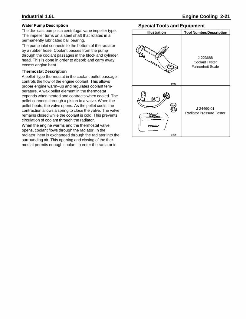
Industrial 1.6L Engine Cooling 2-21
Water Pump DescriptionThe die–cast pump is a centrifugal vane impeller type.The impeller turns on a steel shaft that rotates in apermanently lubricated ball bearing.The pump inlet connects to the bottom of the radiatorby a rubber hose. Coolant passes from the pumpthrough the coolant passages in the block and cylinderhead. This is done in order to absorb and carry awayexcess engine heat.
Thermostat DescriptionA pellet–type thermostat in the coolant outlet passagecontrols the flow of the engine coolant. This allowsproper engine warm–up and regulates coolant tem-perature. A wax pellet element in the thermostatexpands when heated and contracts when cooled. Thepellet connects through a piston to a valve. When thepellet heats, the valve opens. As the pellet cools, thecontraction allows a spring to close the valve. The valveremains closed while the coolant is cold. This preventscirculation of coolant through the radiator.When the engine warms and the thermostat valveopens, coolant flows through the radiator. In theradiator, heat is exchanged through the radiator into thesurrounding air. This opening and closing of the ther-mostat permits enough coolant to enter the radiator in
Special Tools and Equipment
1409
1405
Tool Number/DescriptionIllustration
J 223688Coolant Tester
Fahrenheit Scale
J 24460-01Radiator Pressure Tester

Industrial 1.6L Engine Electrical 3-1
Fastener Notice ........................................................ 3-2Engine Electrical - 1.6L .......................................... 3-3Specifications ......................................................... 3-3Fastener Tightening Specifications ........................... 3-3Battery Usage........................................................... 3-3Starter Motor Usage ................................................. 3-3Generator Usage ...................................................... 3-3Spark Plug Usage..................................................... 3-3Schematic and Routing Diagrams .......................... 3-3Wiring Schematic - Genie 1.6L GM Dual Fuel ............ 3-4Wiring Diagram - 1.6L Generic .................................... 3-5Wiring Schematic - Tennant 1.6L GM GAS/L.P.G. ...... 3-6Component Locator ................................................. 3-7Engine Electrical Components ................................... 3-7Engine Electrical Component Locator Views .............. 3-7Diagnostic Information and Procedures ................. 3-8Charging System Check ............................................ 3-8Starting System Check .............................................. 3-8Battery Common Causes of Failure ............................ 3-9Battery Cautions ........................................................ 3-9Important Battery Diagnosis Information .................... 3-9Battery Check .......................................................... 3-10Battery Terminal Check ............................................ 3-11Battery Not Operating Properly ................................ 3-12Battery Electrical Drain/Parasitic Load ..................... 3-13Current Drain Test ..................................................... 3-16Battery Hydrometer Displays Dark or Yellow Dot ...... 3-18Battery is Undercharged or Overcharged .................. 3-18Engine Cranks/Cranks Slowly but Does Not Start .... 3-19Generator Noise Test ................................................ 3-20Generator Not Operating Properly ............................ 3-20Generator Assembly Bench Check .......................... 3-23Starter Motor Noise Diagnosis ................................. 3-23High-Pitched Whine During Cranking ........................ 3-23High-Pitched Whine after the Engine Fires ............... 3-23Loud Whoop Sound after the Engine Fires ................ 3-24Rumble Growl or Knock ........................................... 3-24Starter No Load Test ................................................ 3-24Starter Solenoid Does Not Click ............................... 3-25Starter Solenoid Clicks, Engine Does Not Crank or
Cranks Slowly .................................................... 3-26
Section 3Engine Electrical
Spark Plug Wires Not Operating Properly ................. 3-28Spark Plug Wire Resistance Test .............................. 3-28Spark Plug Wire Routing .......................................... 3-28Repair Instructions ................................................. 3-28Battery Cable Replacement ...................................... 3-29Battery Charging ...................................................... 3-30Charging Procedure .................................................. 3-30Charging Time Required ........................................... 3-31Battery Charge Low or Completely Discharged ......... 3-32Battery Replacement ............................................... 3-32Jump Starting in Case of Emergency....................... 3-33Jump Starting Procedure ......................................... 3-33Starter Motor Inspection .......................................... 3-34Cleaning Procedure .................................................. 3-34Component Electrical Testing ................................... 3-34Armature Bearing Replacement ................................ 3-34Starter Motor Replacement ...................................... 3-35Generator Replacement ........................................... 3-36DIS Ignition Module Replacement ............................ 3-37Setting Ignition Timing .............................................. 3-37Crankshaft Position (CKP) Sensor Replacement ...... 3-37Description and Operation .................................... 3-39Starting System Description .................................... 3-39Cranking Circuit ....................................................... 3-39Starter Motor ............................................................ 3-39Starting System Circuit Description ......................... 3-39Batteries .................................................................. 3-40
Built-In Hydrometer - If Equipped ........................ 3-40Charging System Description ................................... 3-41SI Series Generators ............................................... 3-41Voltage Regulator ..................................................... 3-42Charging System Circuit Description ........................ 3-42Ignition System Description ..................................... 3-43Ignition Switch ......................................................... 3-43DIS Ignition Module .................................................. 3-43Spark Plugs ............................................................. 3-44Secondary Wiring ..................................................... 3-44Crankshaft Position (CKP) Sensor ........................... 3-44Special Tools and Equipment ............................... 3-45

3-2 Engine Electrical Industrial 1.6L
Fastener NoticeNOTICE: Always use the correct fastener in the proper location. When you replace a fastener, use ONLY the exact partnumber of that application.
UNLESS OTHERWISE SPECIFIED, Do Not use supplemental coatings (paints, greases or other corrosion inhibitors) onthreaded fasteners or fastener joint interfaces. Generally, such coating adversely affect the fastener torque and the jointclamping force, and may damage the fastener.
When you install fasteners, use the correct tightening sequence and specifications.
Following these instructions can help you avoid damage to parts and systems.

Industrial 1.6L Engine Electrical 3-3
Engine Electrical - 1.6L
SpecificationsFastener Tightening Specifications
Battery Usage
Starter Motor Usage
Generator Usage
Cold Cranking Amperes Rating Reserve Capacity Load Test Amperes600 100 340
EngineApplication
Part Number Series
1.6L 93427646 Bosch
Spark Plug Usage
Spark Plug GapEngine Application Spark Plug TypeMetric English
1.6L AC Delco 93206675 0.8 - 0.9 mm 0.031 - 0.035 in
EngineApplication
Generator Series Rated Output(Amperes)
Rotor FieldResistance
(Ohms at 80°F)
Rotation ViewingDrive End
Load Test (Amps)
1.6L 7SI 70 2.1-2.4 CW 91
SpecificationApplication Metric English
Battery Case Retainer Nut or Bolt 18 N•m 13 lb ftBattery Case Top Bar Nut 10 N•m 89 lb inBattery Side Terminal Bolts 12 N•m 106 lb inBattery Top Terminal Nuts 18 N•m 13 lb ftDIS Ignition Module Mounting Bolts 8 N•m 71 lb inGenerator Output (Battery) Terminal Nut 8 N•m 71 lb inBottom Generator to Mounting Bracket Bolt 35 N•m 26 lb ftTop Generator to Bracket Mounting Bolt 20 N•m 15 lb ftSpark Plugs 25 N•m 18 lb ftSolenoid (Starter Motor) Positive (+) Battery Cable Terminal Nut 15 N•m 11 lb ftStarter Motor Mounting Bolt/Stud 25 N•m 18 lb ftStarter Motor S terminal Nut 6.5 N•m 55 lb in
93288991
SCHEMATIC AND ROUTING DIAGRAMSNote: The schematic and wiring diagrams shown on the next few pages are only current up to theprinting date of this book. Please contact Power Solutions, Inc. for additional schematics at 800-551-2938.

3-4 Engine Electrical Industrial 1.6L
80363001
Schematic and Routing Diagrams - Continued

Industrial 1.6L Engine Electrical 3-5
Schematic and Routing Diagrams - Continued
80363010

3-6 Engine Electrical Industrial 1.6L
Schematic and Routing Diagrams - Continued
80363011

Industrial 1.6L Engine Electrical 3-7
80363003
Component LocatorEngine Electrical Components
Engine Electrical Component Locator Views
Name Location Locator View Wiring Diagram
Battery Determined by customer usage and application — N/A
Generator At the RH front of the engine Engine ElectricalComponent Locator
Views
Pages 3xx
Ignition Switch Determined by customer usage and application — N/A
Starter Motor At the lower RH side of the engine Engine ElectricalComponent Locator
Views
N/A
Starter Solenoid On the starter at the lower RH side of theengine
Engine ElectricalComponent Locator
Views
Pages 3xx
Page 3-4
Page 3-4
80363002

3-8 Engine Electrical Industrial 1.6L
Step Action Normal Result(s) Abnormal Result(s)*1 1. Disengage any power
transmission component, ifapplicable.
2. Turn the ignition switch toRUN, leaving the engine off.
The voltmeter shows approximately12 V.
Charging System Check
2 Turn the ignition switch to START. The engine cranks normally and thestarter does not make unusualnoises.
Starter Solenoid Does Not ClickStarter Solenoid Clicks, EngineDoes Not CrankStarter Motor Noise Diagnosis
*Refer to the appropriate symptom diagnostic table for the applicable abnormal result.
Diagnostic Information and ProceduresCharging System Check
Starting System Check
Step Action Normal Result(s) Abnormal Result* / Action1 Check the generator pulley drive
belt tension.The drive belt is correctlytensioned.
Adjust or replace the drive beltRefer to Drive Belt Replacement inEngine Cooling.
2 Visually inspect the battery forphysical damage.
The battery case is not cracked orbroken.
Battery damaged. Replace Battery
3 Inspect the battery terminalconnections.
The battery terminals are clean andtight.
Refer to Fastener TighteningSpecifications; Clean or ReplaceBattery Cable
4 Visually inspect the built–in batteryhydrometer (if equipped).
The battery hydrometer displays agreen dot (if equipped).
Battery Hydrometer Displays Darkor Yellow Dot (if equipped)
5 Inspect the generator outputterminal for a loose connection.
The generator output terminal isclean and tight.
Refer to Fastener TighteningSpecifications
6 Inspect the generator connector forlooseness or damaged terminals.
Generator connector terminals arenot loose or damaged.
Connector Repairs
7 Battery Not Operating Properly The battery passes the load test. Replace Battery
8 Generator Not Operating Properly The generator passes the electricaltest.
Refer to Generator Replacement
9 1. Connect a digital multimeteracross the battery terminals.
2. Start the engine and allow it toidle.
The volts gauge in the instrumentcluster is in the normal range.
*Voltmeter Displaying High or Low
10 Increase the engine speed to 2500RPM.
The volts gauge in the instrumentcluster is in the normal range.
*Voltmeter Displaying High or Low
*Refer to the appropriate symptom diagnostic table for the applicable abnormal result.
The voltmeter is in the normalrange.
The voltmeter is in the normalrange.

Industrial 1.6L Engine Electrical 3-9
Battery Common Causes of Failure• The battery may be damaged.
- Cracked case- Corroded battery cable terminals- Loose battery cable connections- Loose battery hold–down- There may be a mechanical problem.- Loose or slipping drive belt- Structural failure of aftermarket mounting brackets- Misaligned pulleys
• There may be an electrical drain caused by a parasitic load.• The electrical load may be greater than the output of the generator.• There may be an electrical problem in the charging system.
- Poor ground circuits- Electrical shorts- Faulty generator
Battery CautionsCaution: Batteries produce explosive gases. Batteries contain corrosive acid. Batteries supply levels ofelectrical current high enough to cause burns. Therefore, in order to reduce the risk of personal injury whileworking near a battery, observe the following guidelines:
• Always shield your eyes.• Avoid leaning over the battery whenever possible.• Do not expose the battery to open flames or sparks.• Do not allow battery acid to contact the eyes or the skin.
- Flush any contacted areas with water immediately and thoroughly.- Get medical help.
Important Battery Diagnosis Information
PSI does not supply batteries to equipment manufacturers. However, on the following pages, you will find somegeneric methods used to diagnosis common battery problems. You may need to contact the equipment manufacturerfor specific procedures for the battery you are working with.

3-10 Engine Electrical Industrial 1.6L
Battery Check
Step Action Normal Result(s) Abnormal Result(s)*1 1. Inspect the following areas
for battery acid:• The battery case• The battery tray• The area around and
underneath the battery tray2. Inspect the battery for a
cracked, broken, or damaged case.
• The battery case, the batterytray, and the surroundingarea are dry.
• The battery is not cracked,broken, or damaged.
Replace battery.
2 Compare the Cold CrankingAmperage (CCA) and the ReserveCapacity (RC) of the battery or theEquipment Manufacturer'sspecification
The ratings of the vehicle batterymeet or exceed the CCA and theRC of the original equipmentspecification.
Replace battery.
3 Inspect the battery hydrometer for agreen dot (if equipped).
The battery hydrometer displays agreen dot.
• If the battery hydrometer has adark dot (no green dot visible),test the condition of thebattery. Refer to Battery NotOperating Properly.
• If the battery hydrometer has ayellow dot, check the batteryfor low electrolyte. Refer toBattery Hydrometer DisplaysDark or Yellow Dot.
4 Turn the ignition key to START andcheck to see if the engine cranksnormally and starts.
The engine cranks normally andstarts.
• Engine does not crank orcranks slowly, refer to BatteryNot Operating Properly.
• Engine cranks normally butdoes not start, refer to EngineCranks But Does Not Run inEngine Controls.
• Engine starts but does not startovernight or after a couple ofdays, refer to Charging SystemCheck and Battery ElectricalDrain/Parasitic Load.
5 1. Inspect the battery for properinstallation and retention in thebattery tray.
2. Inspect the battery terminalsfor clean and tight connections.
• The battery is firmly held inplace in the tray and the hold–down bolt is properly tightened.
• The battery terminals are cleanand tight.
• Install the battery in the batterytray correctly.
• Refer to Battery TerminalCheck.
*Refer to the appropriate symptom diagnostic table for the applicable abnormal result.

Industrial 1.6L Engine Electrical 3-11
Battery Terminal Checkq¯¤ _¢¯¨¬« t ©°¤F®G w¤® l¬
a °¯¨¬«X>p¤¥¤ >¯¬>` ¯¯¤ ´>a °¯¨¬«®>¬«> ¦¤>QKUL
O OL r°�«>¯§¤>¨¦«¨¯¨¬«>�¤´>¯¬>¯§¤>mdd>¬®¨¯¨¬«L
PL _¯¯¤ª¯>¯¬>�¬¯ ¯¤>¯§¤>«¤¦ ¯¨±¤>FKG>¡ ¯¯¤�´>¢ ¡©¤¢¬««¤¢¯¬�>¢©¬¢�²¨®¤>²¨¯§>©¨¦§¯>¥¨«¦¤�>�¤®®°�¤L
b¬¤®>¯§¤>«¤¦ ¯¨±¤>FKG>¢¬««¤¢¯¬�>�¬¯ ¯¤]
Å
e¬>¯¬>q¯¤>P e¬>¯¬>q¯¤>Q
P s®¤> >¯¬�&°¤>²�¤«¢§>¨«>¬�£¤�>¯¬>±¤�¨¥´>¯§¤>¯¬�&°¤>¯¬>©¬¬®¤«
¯§¤>«¤¦ ¯¨±¤>FKG>¡ ¯¯¤�´>¯¤�ª¨« ©>¡¬©¯Lg®>¯§¤>¯¬�&°¤> ¡¬±¤>¯§¤>®¤¢¨¥¨¤£>± ©°¤]
ON>lĪFVR>©¡>¨«G
e¬>¯¬>q¯¤>R e¬>¯¬>q¯¤>Q
Q b¨®¢¬««¤¢¯>¯§¤>«¤¦ ¯¨±¤>FKG>¡ ¯¯¤�´>¢ ¡©¤Lg®>¯§¤>¢ ¡©¤>£¨®¢¬««¤¢¯¤£]
Åe¬>¯¬>q¯¤>S
Å
R c«®°�¤>¯§¤>«¤¦ ¯¨±¤>FKG>¡ ¯¯¤�´>¢ ¡©¤>¨®>£¨®¢¬««¤¢¯¤£Lg«®¤¢¯>¥¬�>¯§¤>¥¬©©¬²¨«¦>¢¬«£¨¯¨¬«®> «£>�¤ ¨�> ®>«¤¤£¤£X
• r§¤>¢ ¡©¤>¡¬©¯>¨®>¯¬¬>©¬«¦>¬�>ª¨®¥¬�ª¤£> ¯>¯§¤>¤«£L• r§¤�¤>¨®>¥¬�¤¨¦«>ª ¯¤�¨ ©>�¤®¤«¯>¨«®¨£¤>¯§¤>«°¯>¨«
¯§¤>¡ ¯¯¤�´>¯¤�ª¨« ©L• b ª ¦¤>¯¬>¯§¤>¡ ¯¯¤�´>¯¤�ª¨« ©>¥ ¢¤>¬�>¢ ¡©¤
¢¬««¤¢¯¬�>�¨«¦Lg®>¯§¤>�¤ ¨�>¢¬ª©¤¯¤]
Å
e¬>¯¬>q¯¤>S
Å
S p¬¯ ¯¤>¯§¤>¬®¨¯¨±¤>FIG>¡ ¯¯¤�´>¢ ¡©¤>¢¬««¤¢¯¬�>¢©¬¢�²¨®¤²¨¯§>©¨¦§¯>¥¨«¦¤�>�¤®®°�¤Lb¬¤®>¯§¤>¬®¨¯¨±¤>FIG>¢¬««¤¢¯¬�>�¬¯ ¯¤]
Å
e¬>¯¬>q¯¤>T e¬>¯¬>q¯¤>U
T s®¤> >¯¬�&°¤>²�¤«¢§>¨«>¬�£¤�>¯¬>±¤�¨¥´>¯§¤>¯¬�&°¤>¯¬>©¬¬®¤«¯§¤>¬®¨¯¨±¤>FIG>¡ ¯¯¤�´>¯¤�ª¨« ©>¡¬©¯Lg®>¯§¤>¯¬�&°¤> ¡¬±¤>¯§¤>®¤¢¨¥¨¤£>± ©°¤]
ON>lĪ
FVR>©¡>¨«Ge¬>¯¬>q¯¤>V e¬>¯¬>q¯¤>U
U b¨®¢¬««¤¢¯>¯§¤>¬®¨¯¨±¤>FIG>¡ ¯¯¤�´>¢ ¡©¤Lg®>¯§¤>¢ ¡©¤>£¨®¢¬««¤¢¯¤£]
Åe¬>¯¬>q¯¤>W
Å
V OL c«®°�¤>¯§¤>¬®¨¯¨±¤>FIG>¡ ¯¯¤�´>¢ ¡©¤>¨®>£¨®¢¬««¤¢¯¤£LPL g«®¤¢¯>¥¬�>¯§¤>¥¬©©¬²¨«¦>¢¬«£¨¯¨¬«®> «£>�¤ ¨�> ®
«¤¤£¤£X• r§¤>¢ ¡©¤>¡¬©¯>¨®>¯¬¬>©¬«¦>¬�>ª¨®¥¬�ª¤£> ¯>¯§¤>¤«£L• r§¤�¤>¨®>¥¬�¤¨¦«>ª ¯¤�¨ ©>�¤®¤«¯>¨«®¨£¤>¯§¤>«°¯>¨«
¯§¤>¡ ¯¯¤�´>¯¤�ª¨« ©L• b ª ¦¤>¯¬>¯§¤>¡ ¯¯¤�´>¯¤�ª¨« ©>¥ ¢¤>¬�>¢ ¡©¤
¢¬««¤¢¯¬�>�¨«¦Lg®>¯§¤>�¤ ¨�>¢¬ª©¤¯¤]
Å
e¬>¯¬>q¯¤>W
Å
W OL a©¤ «> «£>²¨�¤>¡�°®§>¯§¤>©¤ £>¥ ¢¤>¬¥>¡¬¯§>¡ ¯¯¤�´¯¤�ª¨« ©®> «£>¯§¤>ª¤¯ ©>¢¬«¯ ¢¯>�¨«¦®>¨«>¡¬¯§>¢ ¡©¤¢¬««¤¢¯¬�®L
PL p¤ª¬±¤>¯§¤>¡¬©¯®>¥�¬ª>¯§¤>¢ ¡©¤>¢¬««¤¢¯¬�®>¨«>¬�£¤�¯¬>�¬±¨£¤> ¢¢¤®®>¯¬>¯§¤>¢¬««¤¢¯¬�>�¨«¦®> ®>«¤¤£¤£L
QL g¥>¤¨¯§¤�>¯§¤>¡ ¯¯¤�´>¯¤�ª¨« ©®>¬�>¯§¤>¢ ¡©¤>�¨«¦®> �¤¤³¢¤®®¨±¤©´>£ ª ¦¤£>¬�>¢¬��¬£¤£J>�¤© ¢¤> ®>«¤¤£¤£L
_�¤>¯§¤>ª¤¯ ©>¢¬««¤¢¯¨«¦> �¯®>¢©¤ «> «£>¨«>¦¬¬£¢¬«£¨¯¨¬«]
Å
e¬>¯¬>q¯¤>ON
Å

3-12 Engine Electrical Industrial 1.6L
Battery Terminal Check (cont�d)
q¯¤ _¢¯¨¬« t ©°¤F®G w¤® l¬
ON OL a¬««¤¢¯>¯§¤>¬®¨¯¨±¤>FIG>¡ ¯¯¤�´>¢ ¡©¤>¯¬>¯§¤>¡ ¯¯¤�´¬®¨¯¨±¤>FIG>¯¤�ª¨« ©L
PL r¨¦§¯¤«>¯§¤>¢ ¡©¤>¡¬©¯>¯¬>¯§¤>®¤¢¨¥¨¤£>± ©°¤Lg®>¯§¤>¢ ¡©¤>¡¬©¯>�¬¤�©´>¯¨¦§¯¤«¤£]
OP>lĪFONT>©¡>¨«G
e¬>¯¬>q¯¤>OO
Å
OO OL a¬««¤¢¯>¯§¤>«¤¦ ¯¨±¤>F-G>¡ ¯¯¤�´>¢ ¡©¤>¯¬>¯§¤>¡ ¯¯¤�´«¤¦ ¯¨±¤>FKG>¯¤�ª¨« ©L
PL r¨¦§¯¤«>¯§¤>¢ ¡©¤>¡¬©¯>¯¬>¯§¤>®¤¢¨¥¨¤£>± ©°¤Lg®>¯§¤>¢ ¡©¤>¡¬©¯>�¬¤�©´>¯¨¦§¯¤«¤£]
OP>lĪFONT>©¡>¨«G
` ¯¯¤�´>r¤�ª¨« ©®mi
Å
Battery Not Operating ProperlyNotice: Always turn the ignition switch OFF whenconnecting or disconnecting batteries, battery chargers,or jumper cables. Failure to do so may damage theelectronic control unit or other electrical components.
Important: The battery test using the J 42000 BatteryTester requires correct connections to the batteryterminals. A failure to obtain the correct connectionsduring the test may result in replacing the batteryunnecessarily. Adhere to the following instructions inorder to avoid an incorrect diagnosis due to poorconnections:
• When testing the equipment with the batterycables still connected, rock the J 42000 clipsback and forth on the terminal bolt in order tocut through any coating or oxidation that maybe present on the bolt.
• Even new bolts contain a protective coatingthat may insulate or cause a resistance in thetest circuit.
• If it is uncertain that correct connections canbe made to the battery terminal bolts in theequipment, perform the following steps:
1. Disconnect the battery cables.
2. Install the test adapters on the terminals.
3. Follow the instructions for testing thebattery outside of the equipment.
• If a REPLACE BATTERY result is obtained fora battery tested in the equipment with thebattery cables connected, perform the followingsteps:
1. Disconnect the battery cables.
2. Install the approved battery terminal
adapters.
3. Follow the instructions for testing thebattery outside of the equipment.
4. Replace the battery only if the second testshows a REPLACE BATTERY result.
• For warranty purposes, use the test codefrom the second test.
• On side post batteries, use the approvedterminal adapters. Do not use any commonbolts or a combination of bolts, nut, andwashers as adapters when testing the battery.
• Use the test adapters that are provided withthe J 42000 tester or GM part number12303040 terminal adapters. If the adaptersthat are provided with the J 42000 testerrequire replacement, only use adapters withthe GM part number 12303040. Any otheradapters may not contact the correct areas ofthe battery terminal, causing resistance thatmay result in an invalid battery test result.
• In order to test the top terminal, threaded studbatteries outside of the equipment, use GMpart number 12303040 adapters. Do notconnect the tester to the plain threadedterminals.
Important: For warranty purposes, always place thetest code displayed by the tester on the repair order.The number is a unique identifier that describes thetest data for a particular battery at a particular time.
While the test code may occasionally repeat whenretesting the same battery, it is more likely that adifferent code will result each time the battery is tested.

Industrial 1.6L Engine Electrical 3-13
Battery Not Operating Properlyq¯¤ _¢¯¨¬« t ©°¤F®G w¤® l¬
r¬¬©®>p¤�°¨�¤£h>RPNNN>` ¯¯¤�´>r¤®¯¤�h>QWPNN>b¨¦¨¯ ©>k°©¯¨ª¤¯¤�>FbkkG
nMl>OPQNQNRN>` ¯¯¤�´>r¤�ª¨« ©>_£ ¯¤�®>Fq¨£¤>n¬®¯>` ¯¯¤�¨¤®>m«©´G
O f ®>¯§¤>` ¯¯¤�´>a§¤¢�>¡¤¤«>¤�¥¬�ª¤£] Åe¬>¯¬>q¯¤>P
e¬>¯¬>` ¯¯¤�´a§¤¢�L
P g®>¯§¤>¡ ¯¯¤�´>¨«>¯§¤>±¤§¨¢©¤J>²¨¯§>¯§¤>¡ ¯¯¤�´>¢ ¡©¤®¢¬««¤¢¯¤£]
Åe¬>¯¬>q¯¤>R e¬>¯¬>q¯¤>Q
Q OL j¨¦§¯©´>²¨�¤>¡�°®§>¯§¤>©¤ £>¥ ¢¤®>¬¥>¡¬¯§>¡ ¯¯¤�´¯¤�ª¨« ©®L
PL g«®¯ ©©>¯§¤>¯¤�ª¨« ©> £ ¯¤�®>¯¬>¡¬¯§>¬¥>¯§¤>¡ ¯¯¤�´¯¤�ª¨« ©®L>p¤¥¤�>¯¬>nMl>OPQNQNRNL
_�¤>¯§¤>¡ ¯¯¤�´>¯¤�ª¨« ©> £ ¯¤�®>¨«®¯ ©©¤£]
Å
e¬>¯¬>q¯¤>T
Å
R c«®°�¤>¯§ ¯>¯§¤>¡ ¯¯¤�´>¯¤�ª¨« ©®> �¤>¢©¤ «J>¯¨¦§¯J> «£>¨«¦¬¬£>¢¬«£¨¯¨¬«_�¤>¯§¤>¯¤�ª¨« ©>¢¬««¤¢¯¨¬«®>mi]
Å
e¬>¯¬>q¯¤>Se¬>¯¬>` ¯¯¤�´
r¤�ª¨« ©>a§¤¢�L
S OL r°�«>¯§¤>¨¦«¨¯¨¬«>®²¨¯¢§>¯¬>¯§¤>mdd>¬®¨¯¨¬«LPL r°�«>¯§¤>¤©¤¢¯�¨¢ ©>©¬ £®> «£> ©©> ¢¢¤®®¬�´>©¨¦§¯®>¯¬>¯§¤
mdd>¬®¨¯¨¬«L_�¤> ©©>¬¥>¯§¤>¤©¤¢¯�¨¢ ©>©¬ £®> «£> ¢¢¤®®¬�´>©¨¦§¯®>mdd]
Å
e¬>¯¬>q¯¤>T
Å
T gª¬�¯ «¯X>u§¤«>¯¤®¯¨«¦>¯§¤>¡ ¯¯¤�´>¬«>¯§¤>¤&°¨ª¤«¯J¢¬««¤¢¯>¯§¤>¯¤®¯¤�>£¨�¤¢¯©´>¯¬>¯§¤>¢ ¡©¤>¡¬©¯®L>b¬>«¬¯¢¬««¤¢¯>¤¨¯§¤�>¬¥>¯§¤>¯¤®¯¤�>¢© ª®>¯¬> >�¤ª¬¯¤>¯¤�ª¨« ©J®°¢§> ®> >\°«¢¯¨¬«>¡©¬¢�>¬�> >\°ª>®¯ �¯>¯¤�ª¨« ©L>r§¤>°®¤¬¥> >�¤ª¬¯¤>¯¤�ª¨« ©>²¨©©>¢ °®¤>¨«± ©¨£>¯¤®¯>�¤®°©¯®L
OL a¬««¤¢¯>¯§¤>�¤£>¢© ª>¬«>¯§¤>h>RPNNN>¯¬>¯§¤> £ ¯¤�¬�>¯§¤>¢ ¡©¤>¡¬©¯>¬«>¯§¤>¡ ¯¯¤�´>¬®¨¯¨±¤>FIG>¯¤�ª¨« ©L
PL a¬««¤¢¯>¯§¤>¡© ¢�>¢© ª>¬«>¯§¤>¯¤®¯¤�>¯¬>¯§¤> £ ¯¤�
¬�>¢ ¡©¤>¡¬©¯>¬«>¯§¤>¡ ¯¯¤�´>«¤¦ ¯¨±¤>FKG>¯¤�ª¨« ©LQL p¬¢�>¡¬¯§>¬¥>¯§¤>¯¤®¯¤�>¢© ª®>¡ ¢�> «£>¥¬�¯§>¨«>¬�£¤�
¯¬>¢°¯>¯§�¬°¦§>¯¬>¯§¤>¡ �¤>ª¤¯ ©Lr§¤>ª¤®® ¦¤>ek>kgapm>RON>®§¬°©£> ¤ �>¥¬�> >®§¬�¯¯¨ª¤>¬«>¯§¤>¯¤®¯¤�>£¨®© ´J> «£>¯§¤«>¢§ «¦¤>¯¬>qcjcarrcqrLb¬¤®>¯§¤>£¨®© ´>�¤ £>qcjcar>rcqr]
Å
e¬>¯¬>q¯¤>ON e¬>¯¬>q¯¤>U
U b¬¤®> >afcai>amllcargml>ª¤®® ¦¤> ¤ �>¬«>¯§¤h>RPNNN>¯¤®¯¤�>£¨®© ´]
Åe¬>¯¬>q¯¤>V e¬>¯¬>q¯¤>W
V g«®¤¢¯>¯§¤>¯¤®¯¤�>¢¬««¤¢¯¨¬«®>¯¬>¯§¤>¡ ¯¯¤�´>¯¤�ª¨« © £ ¯¤�®>¬�>¢ ¡©¤>¡¬©¯®>¥¬�>¯§¤>¥¬©©¬²¨«¦>¢¬«£¨¯¨¬«®X
• `¬¯§>®¨£¤®>¬¥>¤ ¢§>¯¤®¯¤�>¢© ª>ª°®¯>ª �¤>¯§¤¢¬��¤¢¯>¢¬«¯ ¢¯L
• c«®°�¤>¯§ ¯>¯§¤>�¤£>¢© ª>¨®>¢¬««¤¢¯¤£>¯¬>¯§¤¬®¨¯¨±¤>FIG>¯¤�ª¨« ©> «£>¯§¤>¡© ¢�>¢© ª>¨®
¢¬««¤¢¯¤£>¯¬>¯§¤>«¤¦ ¯¨±¤>FKG>¯¤�ª¨« ©L
• I¥>¯§¤> £ ¯¤�®>¬�>¯§¤>¡¬©¯®> ¤ �>¢¬��¬£¤£J>�¬¢�¯§¤>¢© ª®>¡ ¢�> «£>¥¬�¯§>¨«>¬�£¤�>¯¬>¤«®°�¤> ¢¬��¤¢¯>¢¬««¤¢¯¨¬«L
• s®¤> >²¨�¤>¡�°®§>¨«>¬�£¤�>¯¬>¢©¤ «>¯§¤> £ ¯¤�®>¬�¢ ¡©¤>¡¬©¯®J>¨¥>«¤¤£¤£L
b¬¤®>¯§¤>¯¤®¯¤�>£¨®© ´>«¬²>�¤ £>qcjcar>rcqr]
Å
e¬>¯¬>q¯¤>OU e¬>¯¬>q¯¤>OP

3-14 Engine Electrical Industrial 1.6L
Battery Not Operating Properly (cont�d)
q¯¤ _¢¯¨¬« t ©°¤F®G w¤® l¬
W s®¤> >h>QWPNN>£¨¦¨¯ ©>ª°©¯¨ª¤¯¤�>FbkkG>¨«>¬�£¤�>¯¬>¯¤®¯>¯§¤¡ ¯¯¤�´>±¬©¯ ¦¤>²¨¯§>¯§¤>h>RPNNN>¯¤®¯¤�>¢¬««¤¢¯¤£Lg®>¯§¤>±¬©¯ ¦¤> ¯>¬�>¡¤©¬²>¯§¤>®¤¢¨¥¨¤£>± ©°¤]
SLS>t
e¬>¯¬>q¯¤>PS e¬>¯¬>q¯¤>PW
ON s®¤>¯§¤>®¢�¬©©>�¤´®>¬«>¯§¤>h>RPNNN>¯¤®¯¤�>¯¬>®¤©¤¢¯>¤¨¯§¤�gl^tcfgajc>F¥¬�>¬«K¤&°¨ª¤«¯>¯¤®¯¨«¦G>¬�>msr^md^tcfgajc>F¥¬�>¬¥¥K¤&°¨ª¤«¯>¯¤®¯¨«¦GJ>£¤¤«£¨«¦>¬«>¯§¤¥¬©©¬²¨«¦>¢¬«£¨¯¨¬«®X
• s®¤>gl^tcfgajc>¯¤®¯¨«¦>¨¥>¯§¤>¡ ¯¯¤�´>¢ ¡©¤®> �¤¢¬««¤¢¯¤£>¯¬>¯§¤>¡ ¯¯¤�´L
• s®¤>msr^md^tcfgajc>¯¤®¯¨«¦>¨¥>¯§¤>¡ ¯¯¤�´¢ ¡©¤®> �¤>£¨®¢¬««¤¢¯¤£> «£>¯§¤>¯¤�ª¨« ©> £ ¯¤�® �¤>¨«®¯ ©©¤£L
u ®>gl^tcfgajc>¯¤®¯¨«¦>®¤©¤¢¯¤£]
Å
e¬>¯¬>q¯¤>OO e¬>¯¬>q¯¤>OP
OO r§¤>£¨®© ´>¬«>¯§¤>¯¤®¯¤�>²¨©©>®§¬²>_ju_wq>rcqr>_r`_rrcpw>rcpkgl_jJ> «£>¯§¤«>¢§ «¦¤>¯¬>qcjcarp_rgleLb¬¤®>¯§¤>£¨®© ´>�¤ £>qcjcar>p_rgle]
Å
e¬>¯¬>q¯¤>OQ e¬>¯¬>q¯¤>QU
OP d¬�>¬¥¥>¤&°¨ª¤«¯>¯¤®¯¨«¦J>¯§¤>£¨®© ´>¬«>¯§¤>¯¤®¯¤�>²¨©©®§¬²>sqc>rcpkgl_j>_b_nrcpqJ> «£>¯§¤«>¢§ «¦¤>¯¬qcjcar>p_rgleLb¬¤®>¯§¤>¯¤®¯¤�>£¨®© ´>�¤ £>qcjcar>p_rgle]
Å
e¬>¯¬>q¯¤>OQ e¬>¯¬>q¯¤>QU
OQ gª¬�¯ «¯X>p¤¥¤�>¯¬>¯§¤>` ¯¯¤�´>s® ¦¤>a§ �¯>¬�>c&°¨ª¤«¯ª «°¥ ¢¯°�¤�E®>®¤¢¨¥¨¢ ¯¨¬«®>¥¬�>¯§¤>¢¬��¤¢¯>� ¯¨«¦>¥¬�>¯§¤¬�¨¦¨« ©>¤&°¨ª¤«¯>FmcG>¡ ¯¯¤�´L>g¥> >¡ ¯¯¤�´>²¨¯§> >©¬²¤�¢¬©£>¢� «�¨«¦> ª¤� ¦¤>Faa_G>� ¯¨«¦>§ ®>¡¤¤«>¨«®¯ ©©¤£¬«>¯§¤>¤&°¨ª¤«¯J>¯§¤>¡ ¯¯¤�´>ª ´>«¬¯>¤�¥¬�ª>�¬¤�©´£°�¨«¦>¯§¤>°®¤>¬¥>¯§¤>±¤§¨¢©¤>¤±¤«>¨¥>¯§¤>¡ ¯¯¤�´> ®®¤®>¯§¤¯¤®¯>°®¨«¦>¯§¤>h>RPNNN>¯¤®¯¤�L
OL s®¤>¯§¤>®¢�¬©©>�¤´®>¬«>¯§¤>h>RPNNN>¯¤®¯¤�>¯¬>®¤©¤¢¯>¯§¤aa_>� ¯¨«¦>¬«>¯§¤>¡ ¯¯¤�´>© ¡¤©L
PL n�¤®®>¯§¤>clrcp>�¤´>¬«>¯§¤>¯¤®¯¤�Lrcqrgle>²¨©©> ¤ �>¡�¨¤¥©´>¬«>¯§¤>£¨®© ´J>¥¬©©¬²¤£>¡´>¯§¤�¤®°©¯®>¬¥>¯§¤>¯¤®¯L_�¤>¯§¤>�¤®°©¯®>¬¥>¯§¤>¯¤®¯>£¨®© ´¤£]
Å
e¬>¯¬>q¯¤>OR
Å
OR b¬¤®>emmb>`_rrcpw> ¤ �>¬«>¯§¤>h>RPNNN>£¨®© ´] Å e¬>¯¬>q¯¤>PP e¬>¯¬>q¯¤>OS
OS b¬¤®>emmbKpcaf_pec> ¤ �>¬«>¯§¤>¯¤®¯¤�>£¨®© ´] Å e¬>¯¬>q¯¤>PS e¬>¯¬>q¯¤>OT
OT b¬¤®>af_pec> ª>pcrcqr> ¤ �>¬«>¯§¤>¯¤®¯¤�£¨®© ´]
Åe¬>¯¬>q¯¤>PW e¬>¯¬>q¯¤>OU
OU b¬¤®>pcnj_ac>`_rrcpw> ¤ �>¬«>¯§¤>¯¤®¯¤�>£¨®© ´] Å e¬>¯¬>q¯¤>PT e¬>¯¬>q¯¤>OV
OV b¬¤®>`_b>acjjKpcnj_ac> ¤ �>¬«>¯§¤>¯¤®¯¤�>£¨®© ´] Å e¬>¯¬>q¯¤>PV e¬>¯¬>q¯¤>OW
OW b¬¤®>qspd_ac>af_pec>bcrcarcb> ¤ �>¬«>¯§¤¯¤®¯¤�>£¨®© ´]
Åe¬>¯¬>q¯¤>QN e¬>¯¬>q¯¤>PN
PN b¬¤®>qcjcar>rckn> ¤ �>¬«>¯§¤>¯¤®¯¤�>£¨®© ´] Å e¬>¯¬>q¯¤>QQ e¬>¯¬>q¯¤>PO
PO b¬¤®>qwqrck>lmgqcKafcai>jm_bqJ> ©¯¤�« ¯¨«¦>²¨¯§pcrcqrgleJ> ¤ �>¬«>¯§¤>¯¤®¯¤�>£¨®© ´]
Åe¬>¯¬>q¯¤>QR e¬>¯¬>q¯¤>QU
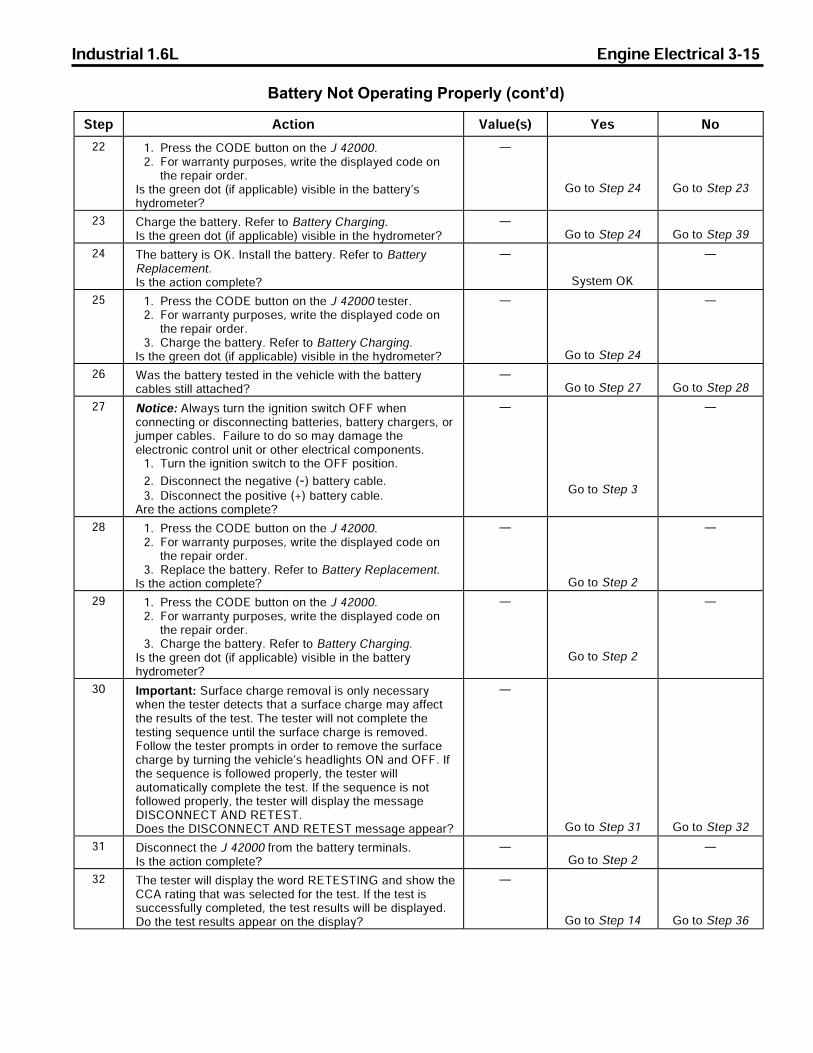
Industrial 1.6L Engine Electrical 3-15
Battery Not Operating Properly (cont�d)
q¯¤ _¢¯¨¬« t ©°¤F®G w¤® l¬
PP OL n�¤®®>¯§¤>ambc>¡°¯¯¬«>¬«>¯§¤>h>RPNNNLPL d¬�>² �� «¯´>°�¬®¤®J>²�¨¯¤>¯§¤>£¨®© ´¤£>¢¬£¤>¬«
¯§¤>�¤ ¨�>¬�£¤�Lg®>¯§¤>¦�¤¤«>£¬¯>F¨¥> ©¨¢ ¡©¤G>±¨®¨¡©¤>¨«>¯§¤>¡ ¯¯¤�´j®§´£�¬ª¤¯¤�]
Å
e¬>¯¬>q¯¤>PR e¬>¯¬>q¯¤>PQ
PQ a§ �¦¤>¯§¤>¡ ¯¯¤�´L>p¤¥¤�>¯¬>` ¯¯¤�´>a§ �¦¨«¦Lg®>¯§¤>¦�¤¤«>£¬¯>F¨¥> ©¨¢ ¡©¤G>±¨®¨¡©¤>¨«>¯§¤>§´£�¬ª¤¯¤�]
Åe¬>¯¬>q¯¤>PR e¬>¯¬>q¯¤>QW
PR r§¤>¡ ¯¯¤�´>¨®>miL>g«®¯ ©©>¯§¤>¡ ¯¯¤�´L>p¤¥¤�>¯¬>` ¯¯¤�´p¤© ¢¤ª¤«¯Lg®>¯§¤> ¢¯¨¬«>¢¬ª©¤¯¤]
Å
q´®¯¤ª>mi
Å
PS OL n�¤®®>¯§¤>ambc>¡°¯¯¬«>¬«>¯§¤>h>RPNNN>¯¤®¯¤�LPL d¬�>² �� «¯´>°�¬®¤®J>²�¨¯¤>¯§¤>£¨®© ´¤£>¢¬£¤>¬«
¯§¤>�¤ ¨�>¬�£¤�LQL a§ �¦¤>¯§¤>¡ ¯¯¤�´L>p¤¥¤�>¯¬>` ¯¯¤�´>a§ �¦¨«¦L
g®>¯§¤>¦�¤¤«>£¬¯>F¨¥> ©¨¢ ¡©¤G>±¨®¨¡©¤>¨«>¯§¤>§´£�¬ª¤¯¤�]
Å
e¬>¯¬>q¯¤>PR
Å
PT u ®>¯§¤>¡ ¯¯¤�´>¯¤®¯¤£>¨«>¯§¤>±¤§¨¢©¤>²¨¯§>¯§¤>¡ ¯¯¤�´¢ ¡©¤®>®¯¨©©> ¯¯ ¢§¤£]
Åe¬>¯¬>q¯¤>PU e¬>¯¬>q¯¤>PV
PU l¬¯¨¢¤X>_©² ´®>¯°�«>¯§¤>¨¦«¨¯¨¬«>®²¨¯¢§>mdd>²§¤«¢¬««¤¢¯¨«¦>¬�>£¨®¢¬««¤¢¯¨«¦>¡ ¯¯¤�¨¤®J>¡ ¯¯¤�´>¢§ �¦¤�®J>¬�\°ª¤�>¢ ¡©¤®L>>d ¨©°�¤>¯¬>£¬>®¬>ª ´>£ ª ¦¤>¯§¤¤©¤¢¯�¬«¨¢>¢¬«¯�¬©>°«¨¯>¬�>¬¯§¤�>¤©¤¢¯�¨¢ ©>¢¬ª¬«¤«¯®L
OL r°�«>¯§¤>¨¦«¨¯¨¬«>®²¨¯¢§>¯¬>¯§¤>mdd>¬®¨¯¨¬«L
PL b¨®¢¬««¤¢¯>¯§¤>«¤¦ ¯¨±¤>FKG>¡ ¯¯¤�´>¢ ¡©¤LQL b¨®¢¬««¤¢¯>¯§¤>¬®¨¯¨±¤>FIG>¡ ¯¯¤�´>¢ ¡©¤L
_�¤>¯§¤> ¢¯¨¬«®>¢¬ª©¤¯¤]
Å
e¬>¯¬>q¯¤>Q
Å
PV OL n�¤®®>¯§¤>ambc>¡°¯¯¬«>¬«>¯§¤>h>RPNNNLPL d¬�>² �� «¯´>°�¬®¤®J>²�¨¯¤>¯§¤>£¨®© ´¤£>¢¬£¤>¬«
¯§¤>�¤ ¨�>¬�£¤�LQL p¤© ¢¤>¯§¤>¡ ¯¯¤�´L>p¤¥¤�>¯¬>` ¯¯¤�´>p¤© ¢¤ª¤«¯L
g®>¯§¤> ¢¯¨¬«>¢¬ª©¤¯¤]
Å
e¬>¯¬>q¯¤>P
Å
PW OL n�¤®®>¯§¤>ambc>¡°¯¯¬«>¬«>¯§¤>h>RPNNNLPL d¬�>² �� «¯´>°�¬®¤®J>²�¨¯¤>¯§¤>£¨®© ´¤£>¢¬£¤>¬«
¯§¤>�¤ ¨�>¬�£¤�LQL a§ �¦¤>¯§¤>¡ ¯¯¤�´L>p¤¥¤�>¯¬>` ¯¯¤�´>a§ �¦¨«¦L
g®>¯§¤>¦�¤¤«>£¬¯>F¨¥> ©¨¢ ¡©¤G>±¨®¨¡©¤>¨«>¯§¤>¡ ¯¯¤�´§´£�¬ª¤¯¤�]
Å
e¬>¯¬>q¯¤>P
Å
QN gª¬�¯ «¯X>q°�¥ ¢¤>¢§ �¦¤>�¤ª¬± ©>¨®>¬«©´>«¤¢¤®® �´²§¤«>¯§¤>¯¤®¯¤�>£¤¯¤¢¯®>¯§ ¯> >®°�¥ ¢¤>¢§ �¦¤>ª ´> ¥¥¤¢¯¯§¤>�¤®°©¯®>¬¥>¯§¤>¯¤®¯L>r§¤>¯¤®¯¤�>²¨©©>«¬¯>¢¬ª©¤¯¤>¯§¤¯¤®¯¨«¦>®¤&°¤«¢¤>°«¯¨©>¯§¤>®°�¥ ¢¤>¢§ �¦¤>¨®>�¤ª¬±¤£Ld¬©©¬²>¯§¤>¯¤®¯¤�>�¬ª¯®>¨«>¬�£¤�>¯¬>�¤ª¬±¤>¯§¤>®°�¥ ¢¤¢§ �¦¤>¡´>¯°�«¨«¦>¯§¤>±¤§¨¢©¤j®>§¤ £©¨¦§¯®>ml> «£>mddL>g¥¯§¤>®¤&°¤«¢¤>¨®>¥¬©©¬²¤£>�¬¤�©´J>¯§¤>¯¤®¯¤�>²¨©© °¯¬ª ¯¨¢ ©©´>¢¬ª©¤¯¤>¯§¤>¯¤®¯L>g¥>¯§¤>®¤&°¤«¢¤>¨®>«¬¯¥¬©©¬²¤£>�¬¤�©´J>¯§¤>¯¤®¯¤�>²¨©©>£¨®© ´>¯§¤>ª¤®® ¦¤bgqamllcar>_lb>pcrcqrLb¬¤®>¯§¤>bgqamllcar>_lb>pcrcqr>ª¤®® ¦¤> ¤ �]
Å
e¬>¯¬>q¯¤>QO e¬>¯¬>q¯¤>QP
QO b¨®¢¬««¤¢¯>¯§¤>h>RPNNN>¥�¬ª>¯§¤>¡ ¯¯¤�´>¯¤�ª¨« ©®Lg®>¯§¤> ¢¯¨¬«>¢¬ª©¤¯¤]
Åe¬>¯¬>q¯¤>P
Å
QP r§¤>¯¤®¯¤�>²¨©©>£¨®© ´>¯§¤>²¬�£>pcrcqrgle> «£>®§¬²>¯§¤aa_>� ¯¨«¦>¯§ ¯>² ®>®¤©¤¢¯¤£>¥¬�>¯§¤>¯¤®¯L>g¥>¯§¤>¯¤®¯>¨®®°¢¢¤®®¥°©©´>¢¬ª©¤¯¤£J>¯§¤>¯¤®¯>�¤®°©¯®>²¨©©>¡¤>£¨®© ´¤£Lb¬>¯§¤>¯¤®¯>�¤®°©¯®> ¤ �>¬«>¯§¤>£¨®© ´]
Å
e¬>¯¬>q¯¤>OR e¬>¯¬>q¯¤>QT

Industrial 1.6L Engine Electrical 3-21
Generator Not Operating Properly (cont�d)
q¯¤ _¢¯¨¬« t ©°¤F®G w¤® l¬
U OL b¨®¢¬««¤¢¯>¯§¤>«¤¦ ¯¨±¤>¡ ¯¯¤�´>¢ ¡©¤>¥�¬ª>¯§¤>¡ ¯¯¤�´L
PL b¨®¢¬««¤¢¯>¯§¤>¡ ¯¯¤�´>F²§¨¯¤G>²¨�¤>¥�¬ª>¯§¤>¦¤«¤� ¯¬�¡ ¯¯¤�´>¯¤�ª¨« ©L
QL a¬««¤¢¯>¯§¤>�¤£> ªª¤¯¤�>©¤ £>¯¬>¯§¤>¦¤«¤� ¯¬�>¡ ¯¯¤�´¯¤�ª¨« ©> «£>¯§¤>¡© ¢�>©¤ £>¯¬>¯§¤>¦¤«¤� ¯¬�>¡ ¯¯¤�´²¨�¤>¯¤�ª¨« ©L
RL p¤K¢¬««¤¢¯>¯§¤>«¤¦ ¯¨±¤>¡ ¯¯¤�´>¢ ¡©¤>¯¬>¯§¤>¡ ¯¯¤�´LSL m¡®¤�±¨«¦>¬© �¨¯´J>¢¬««¤¢¯>¯§¤>±¬©¯ª¤¯¤�>©¤ £®>¯¬>¯§¤
¬®¨¯¨±¤> «£>«¤¦ ¯¨±¤>¡ ¯¯¤�´>¯¤�ª¨« ©®Lg®>¯§¤>±¬©¯ ¦¤> ¡¬±¤>¯§¤>®¤¢¨¥¨¤£>± ©°¤]
OP>t
e¬>¯¬>q¯¤>W e¬>¯¬>q¯¤>V
V OL p¤¢§¤¢�>¯§¤>¢¬««¤¢¯¨¬«®>¯§ ¯>²¤�¤>ª £¤>¨«>q¯¤>UL
PL a¬��¤¢¯>¯§¤>¢¬««¤¢¯¨¬«®>¨¥>¯§¤´>²¤�¤>�¤±¤�®¤£L
Å
e¬>¯¬>q¯¤>W
Å
W a °¯¨¬«X>k �¤>®°�¤>¯§ ¯>¯§¤>©¬ £>¨®>¢¬ª©¤¯¤©´>¯°�«¤£¬¥¥>¡¤¥¬�¤>¢¬««¤¢¯¨«¦>¬�>£¨®¢¬««¤¢¯¨«¦>¯§¤>¢ �¡¬«>¨©¤©¬ £>¯¤®¯¤�>¯¬>¯§¤>¡ ¯¯¤�´L>>m¯§¤�²¨®¤J>® ��¨«¦>¢¬°©£¨¦«¨¯¤>¡ ¯¯¤�´>¦ ®®¤®>²§¨¢§> �¤>¤³¯�¤ª¤©´>¥© ªª ¡©¤ «£>ª ´>¤³©¬£¤>±¨¬©¤«¯©´L
OL n�¨¬�>¯¬>¢¬««¤¢¯¨«¦> >¢ �¡¬«>¨©¤>©¬ £>¯¤®¯¤�J>¤«®°�¤¯§ ¯>¯§¤>©¬ £>£¨ ©>¬¥>¯§¤>¢ �¡¬«>¨©¤>¯¤®¯¤�>¨®>¯°�«¤£¢¬ª©¤¯¤©´>¯¬>¯§¤>mdd>¬®¨¯¨¬«L>a¬««¤¢¯>¯§¤>¢ ¡©¤©¤ £®>¬¥>¯§¤>¢ �¡¬«>¨©¤>¯¤®¯¤�>¯¬>¯§¤>¡ ¯¯¤�´>¯¤�ª¨« ©®L
PL q¯ �¯>¯§¤>¤«¦¨«¤> «£> ©©¬²>¨¯>¯¬>¨£©¤>¡�¨¤¥©´LQL g«¢�¤ ®¤>¯§¤>¤«¦¨«¤>®¤¤£>¯¬>PSNN>pnkLRL u§¨©¤>ª ¨«¯ ¨«¨«¦>¯§¤>¤«¦¨«¤>®¤¤£> ¯>PSNN>pnk
¨«¢�¤ ®¤>¯§¤>©¬ £>°«¯¨©>¯§¤>¦¤«¤� ¯¬�>¬°¯°¯>¨®>²¨¯§¨«ON> ª®>¬¥>¯§¤>� ¯¤£>¬°¯°¯>F©¬ £>¯¤®¯G>± ©°¤>¦¨±¤«>¨«e¤«¤� ¯¬�>s® ¦¤L
_®>¯§¤>©¬ £>¨®>¨«¢�¤ ®¤£J>¨®>¯§¤>¦¤«¤� ¯¬�>¢ ¡©¤>¬¥�¬£°¢¨«¦>¯§¤>� ¯¤£>¬°¯°¯>± ©°¤>©¬ £>¯¤®¯>¢°��¤«¯>®¤¢¨¥¨¤£¨«>e¤«¤� ¯¬�>s® ¦¤>²¨¯§¨«>ON> ª®]
UN>_
e¬>¯¬>q¯¤>ON
p¤© ¢¤>¬�>�¤ ¨�¯§¤>¦¤«¤� ¯¬�
ON k ¨«¯ ¨«>¯§¤>¤«¦¨«¤>®¤¤£> ¯>PSNN>pnk> «£>¢¬«¯¨«°¤>¯¬¬¤� ¯¤>¯§¤>¦¤«¤� ¯¬�> ¯>¯§¤>©¬ £>¯¤®¯>± ©°¤Lg®>¯§¤>±¬©¯ ¦¤>²¨¯§¨«>¯§¤>®¤¢¨¥¨¤£>± ©°¤]
OQLS>t>¯¬OSLO>t
e¤«¤� ¯¬�>mi e¬>¯¬>q¯¤>OO
OO OL k ¨«¯ ¨«>¯§¤>¤«¦¨«¤>®¤¤£> ¯>PSNN>pnk> «£>¢¬«¯¨«°¤¯¬>¬¤� ¯¤>¯§¤>¦¤«¤� ¯¬�> ¯>¯§¤>©¬ £>¯¤®¯>± ©°¤L
PL a¬««¤¢¯> >£¨¦¨¯ ©>ª°©¯¨ª¤¯¤�>¡¤¯²¤¤«>¯§¤>¦¤«¤� ¯¬�¡ ¯¯¤�´>²¨�¤>¯¤�ª¨« ©>¯¬>¯§¤>¡ ¯¯¤�´>¬®¨¯¨±¤>FIG¯¤�ª¨« ©L
g®>¯§¤>±¬©¯ ¦¤> ¡¬±¤>¯§¤>®¤¢¨¥¨¤£>± ©°¤]
NLS>t
e¬>¯¬>q¯¤>OQ e¬>¯¬>q¯¤>OP
OP OL k ¨«¯ ¨«>¯§¤>¤«¦¨«¤>®¤¤£> ¯>PSNN>pnk> «£>¢¬«¯¨«°¤¯¬>¬¤� ¯¤>¯§¤>¦¤«¤� ¯¬�> ¯>¯§¤>©¬ £>¯¤®¯>± ©°¤L
PL a¬««¤¢¯> >£¨¦¨¯ ©>ª°©¯¨ª¤¯¤�>¥�¬ª>¯§¤>¦¤«¤� ¯¬�>ª¤¯ ©§¬°®¨«¦>¯¬>¯§¤>¡ ¯¯¤�´>«¤¦ ¯¨±¤>F8G>¯¤�ª¨« ©L
g®>¯§¤>±¬©¯ ¦¤> ¡¬±¤>¯§¤>®¤¢¨¥¨¤£>± ©°¤]
NLS>t
e¬>¯¬>q¯¤>OR e¬>¯¬>q¯¤>OS

3-22 Engine Electrical Industrial 1.6L
Generator Not Operating Properly (cont�d)q¯¤ _¢¯¨¬« t ©°¤F®G w¤® l¬
OQ a °¯¨¬«X>k �¤>®°�¤>¯§ ¯>¯§¤>©¬ £>¨®>¢¬ª©¤¯¤©´>¯°�«¤£¬¥¥>¡¤¥¬�¤>¢¬««¤¢¯¨«¦>¬�>£¨®¢¬««¤¢¯¨«¦> >¢ �¡¬«>¨©¤©¬ £>¯¤®¯¤�>¯¬>¯§¤>¡ ¯¯¤�´L>m¯§¤�²¨®¤J>® ��¨«¦>¢¬°©£¨¦«¨¯¤>¡ ¯¯¤�´>¦ ®®¤®>²§¨¢§> �¤>¤³¯�¤ª¤©´>¥© ªª ¡©¤ «£>ª ´>¤³©¬£¤>±¨¬©¤«¯©´L
OL b¨®¢¬««¤¢¯>¯§¤>£¨¦¨¯ ©>ª°©¯¨ª¤¯¤�LPL r°�«>mdd>¯§¤>©¬ £>¨«>¯§¤>¢ �¡¬«>¨©¤>¯¤®¯¤�LQL r°�«>¯§¤>¨¦«¨¯¨¬«>®²¨¯¢§>¯¬>mdd>¯¬>®¯¬>¯§¤>¤«¦¨«¤LRL b¨®¢¬««¤¢¯>¯§¤>¢ �¡¬«>¨©¤>¯¤®¯¤�>¢ ¡©¤®>¥�¬ª>¯§¤
¡ ¯¯¤�´LSL b¨®¢¬««¤¢¯>¯§¤>¡ ¯¯¤�´>«¤¦ ¯¨±¤>¯¤�ª¨« ©LTL g«®¤¢¯>¯§¤>¢¨�¢°¨¯>¡¤¯²¤¤«>¯§¤>¡ ¯¯¤�´>¬®¨¯¨±¤>FIG
¯¤�ª¨« ©> «£>¯§¤>¦¤«¤� ¯¬�>¬°¯°¯>¯¤�ª¨« ©>¥¬�> >§¨¦§8�¤®¨®¯ «¢¤>¢¬««¤¢¯¨¬«L>b¨® ®®¤ª¡©¤> «£>¢©¤ «> ©©¢¬««¤¢¯¨¬«®>¨«>¯§¨®>¢¨�¢°¨¯L
UL _®®¤ª¡©¤>¯§¤>¢¬««¤¢¯¨¬«®> «£>¯¨¦§¯¤«>¯¬®¤¢¨¥¨¢ ¯¨¬«®L
VL a¬««¤¢¯>¯§¤>¡ ¯¯¤�´>«¤¦ ¯¨±¤>F8G>¯¤�ª¨« ©L>r¨¦§¯¤«>¯¬®¤¢¨¥¨¢ ¯¨¬«®L>p¤¥¤�>¯¬>d ®¯¤«¤�>r¨¦§¯¤«¨«¦q¤¢¨¥¨¢ ¯¨¬«®L
g®>¯§¤>�¤ ¨�>¢¬ª©¤¯¤]
Å e¬>¯¬>a§ �¦¨«¦q´®¯¤ª>a§¤¢�
Å
OR a °¯¨¬«X>k �¤>®°�¤>¯§ ¯>¯§¤>©¬ £>¨®>¢¬ª©¤¯¤©´>¯°�«¤£¬¥¥>¡¤¥¬�¤>¢¬««¤¢¯¨«¦>¬�>£¨®¢¬««¤¢¯¨«¦> >¢ �¡¬«>¨©¤©¬ £>¯¤®¯¤�>¯¬>¯§¤>¡ ¯¯¤�´L>m¯§¤�²¨®¤J>® ��¨«¦>¢¬°©£¨¦«¨¯¤>¡ ¯¯¤�´>¦ ®®¤®>²§¨¢§> �¤>¤³¯�¤ª¤©´>¥© ªª ¡©¤ «£>ª ´>¤³©¬£¤>±¨¬©¤«¯©´L
OL b¨®¢¬««¤¢¯>¯§¤>£¨¦¨¯ ©>ª°©¯¨ª¤¯¤�LPL r°�«>mdd>¯§¤>©¬ £>¨«>¯§¤>¢ �¡¬«>¨©¤>¯¤®¯¤�LQL r°�«>¯§¤>¨¦«¨¯¨¬«>®²¨¯¢§>¯¬>mdd>¯¬>®¯¬>¯§¤>¤«¦¨«¤LRL b¨®¢¬««¤¢¯>¯§¤>¢ �¡¬«>¨©¤>¯¤®¯¤�>¢ ¡©¤®>¥�¬ª>¯§¤
¡ ¯¯¤�´LSL g«®¤¢¯>¯§¤>¦�¬°«£>¢¨�¢°¨¯>¥¬�>§¨¦§>�¤®¨®¯ «¢¤>¥�¬ª>¯§¤
¡ ¯¯¤�´>«¤¦ ¯¨±¤>F8G>¯¤�ª¨« ©>¯¬>¯§¤>¦¤«¤� ¯¬�>§¬°®¨«¦Lb¨® ®®¤ª¡©¤> «£>¢©¤ «> ©©>¢¬««¤¢¯¨¬«®L
TL _®®¤ª¡©¤>¯§¤>¢¬««¤¢¯¨¬«®> «£>¯¨¦§¯¤«>¯¬®¤¢¨¥¨¢ ¯¨¬«®L>p¤¥¤�>¯¬>d ®¯¤«¤�>r¨¦§¯¤«¨«¦q¤¢¨¥¨¢ ¯¨¬«®L
g®>¯§¤>�¤ ¨�>¢¬ª©¤¯¤]
Å e¬>¯¬>a§ �¦¨«¦q´®¯¤ª>a§¤¢�
Å
OS p¤© ¢¤>¯§¤>±¬©¯ ¦¤>�¤¦°© ¯¬�Lg®>¯§¤>�¤ ¨�>¢¬ª©¤¯¤]
Å e¬>¯¬>a§ �¦¨«¦q´®¯¤ª>a§¤¢�
Å

Industrial 1.6L Engine Electrical 3-23
STARTER MOTOR NOISE DIAGNOSIS
High-Pitched Whine During Cranking
Generator Assembly Bench CheckThis test requires both a fully charged battery and agenerator test stand to operate the generator. Thegenerator can be tested quicker and easier while it isstill on the equipment. Refer to Generator Not Operat-ing Properly.
1. Ensure the carbon pile is off before making connec-tions as shown.
• The ground polarity of the generator and battery must be the same.• The battery must be fully charged.• Use a 30-500 ohm resistor between the battery and the BAT terminal of the generator.
2. Slowly increase the generator speed and observe thevoltage.
3. If the voltage is uncontrolled and increases above 16volts, the rotor field is shorted, the regulator is notworking properly, or both. A shorted rotor field coilcan cause repeat regulator failure.
4. If the voltage is below 16 volts, increase speed andturn on and adjust the carbon pile to obtain maximumamperage output. Maintain the voltage above 13volts.
5. If the output is within 15 amperes of the rated output,the generator is good. If the output is not within 15amperes of the rated output, replace the generator.
n�¬¡©¤ª _¢¯¨¬«
bcdglgrgmlX>_>§¨¦§8¨¯¢§¤£>²§¨«¤>£°�¨«¦>¢� «�¨«¦>F¡¤¥¬�¤>¯§¤>¤«¦¨«¤>¥¨�¤®GJ>¡°¯>¯§¤>¤«¦¨«¤>¢� «�®> «£>¥¨�¤®>«¬�ª ©©´L
r§¤>£¨®¯ «¢¤>¨®>¯¬¬>¦�¤ ¯>¡¤¯²¤¤«>¯§¤>®¯ �¯¤�¨«¨¬«> «£>¯§¤>¥©´²§¤¤©L
p¤ª¬±¤>¯§¤>®§¨ª®> ¯>¯§¤>®¯ �¯¤�>ª¬°«¯L>p¤¥¤�>¯¬>q¯ �¯¤�>n¨«¨¬«>a©¤ � «¢¤a§¤¢�L
High-Pitched Whine After the Engine Fires
n�¬¡©¤ª _¢¯¨¬«
bcdglgrgmlX>_>§¨¦§8¨¯¢§¤£>²§¨«¤J> ¥¯¤�>¯§¤>¤«¦¨«¤>¥¨�¤®J> ®>¯§¤>�¤´>¨®>¡¤¨«¦>�¤©¤ ®¤£L>r§¤>¤«¦¨«¤>¢� «�®> «£>¥¨�¤®«¬�ª ©©´L>r§¨®>¢¬ª© ¨«¯>¨®>¬¥¯¤«>£¨ ¦«¬®¤£> ®>®¯ �¯¤�>§ «¦8¨«>¬�>®¬©¤«¬¨£>²¤ �L
r§¤>£¨®¯ «¢¤>¨®>¯¬¬>®ª ©©>¡¤¯²¤¤«>¯§¤>®¯ �¯¤�¨«¨¬«> «£>¯§¤>¥©´²§¤¤©>F¥©´²§¤¤©>�°«¬°¯¢¬«¯�¨¡°¯¤®>¯¬>¯§¤>¨«¯¤�ª¨¯¯¤«¯>« ¯°�¤>¬¥>¯§¤�¬¡©¤ªGL
_££>®§¨ª®> ¯>¯§¤>®¯ �¯¤�>ª¬°«¯L>p¤¥¤�>¯¬>q¯ �¯¤�>n¨«¨¬«>a©¤ � «¢¤>a§¤¢�L
350774

3-24 Engine Electrical Industrial 1.6L
Starter No Load Test
Tools Required• J 35590 Current Clamp• J 39200 Digital Multimeter, or Equivalent
Notice: Never operate the starter motor more than 15seconds at a time without pausing in order to allow it tocool for at least 2 minutes. Overheating will damage thestarter motor.
Important: Verify that the battery is in good condition.Refer to Battery Check.
1. Disable the fuel system. Refer to EngineControls.
2. Calculate the current draw by doing the following:
2.1. Select the 200 amp or the 2000 amp scaleon the J 35590.
2.2. Zero the current clamp.2.3. Clamp the current clamp to the battery
negative cable.2.4. Crank the engine and observe the meter
readings. The reading should be 65-95 amps.
• If the amperage is over 95 amps, an internal starter failure may be the cause.
• If the amperage is under 65 amps, a battery cable or connection may be the cause.
Loud Whoop Sound after the Engine Fires
Rumble, Growl, or a Knock
n�¬¡©¤ª _¢¯¨¬«
bcdglgrgmlX>_>©¬°£>²§¬¬>®¬°«£> ¥¯¤�>¯§¤>¤«¦¨«¤>¥¨�¤®J>¡°¯>²§¨©¤>¯§¤>®¯ �¯¤�>¨®>®¯¨©©>§¤©£>¤«¦ ¦¤£L>r§¤>®¬°«£>¨®>®¨ª¨© �>¯¬> ®¨�¤«>¨¥>¯§¤>¤«¦¨«¤>¨®>�¤±±¤£>²§¨©¤>¯§¤>®¯ �¯¤�>¨®>¤«¦ ¦¤£L
r§¤>®¯ �¯¤�>ª¬¯¬�>¢©°¯¢§>¨®>²¬�«L OL p¤ª¬±¤>¯§¤>®¯ �¯¤�>ª¬¯¬�L>p¤¥¤�>¯¬>q¯ �¯¤�>k¬¯¬�>p¤© ¢¤ª¤«¯LPL a§¤¢�>¯§¤>¢©°¯¢§L>p¤¥¤�>¯¬>q¯ �¯¤�>k¬¯¬�>g«®¤¢¯¨¬«L
n�¬¡©¤ª _¢¯¨¬«
bcdglgrgmlX>_>�°ª¡©¤J>¦�¬²©J>¬�> >�«¬¢�>F¨«>®¤±¤�¤>¢ ®¤®G> ®>¯§¤>®¯ �¯¤�>¨®>¢¬ ®¯¨«¦>£¬²«>¯¬> >®¯¬> ¥¯¤�>®¯ �¯¨«¦>¯§¤¤«¦¨«¤L
r§¤>®¯ �¯¤�> �ª ¯°�¤>¨®>¡¤«¯>¬�>°«¡ © «¢¤£L OL p¤ª¬±¤>¯§¤>®¯ �¯¤�>ª¬¯¬�L>p¤¥¤�>¯¬>q¯ �¯¤�>k¬¯¬�>p¤© ¢¤ª¤«¯LPL a§¤¢�>¯§¤>¢©°¯¢§L>p¤¥¤�>¯¬>q¯ �¯¤�>k¬¯¬�>g«®¤¢¯¨¬«L
182233

Industrial 1.6L Engine Electrical 3-25
Starter Solenoid Does Not Click
q¯¤ _¢¯¨¬« t ©°¤F®G w¤® l¬
O f ®>¯§¤>` ¯¯¤�´>a§¤¢�>¡¤¤«>¤�¥¬�ª¤£] Åe¬>¯¬>q¯¤>P
e¬>¯¬>` ¯¯¤�´a§¤¢�L
P OL n�¬¡¤>¯§¤>®¯ �¯¤�>®¬©¤«¬¨£>²¨¯§> >£¨¦¨¯ ©>ª°©¯¨ª¤¯¤�¥�¬ª>¯¤�ª¨« ©>q>¯¬>¤«¦¨«¤>¦�¬°«£L
PL r°�«>¯§¤>¨¦«¨¯¨¬«>®²¨¯¢§>¯¬>¯§¤>qr_pr>¬®¨¯¨¬«Lb¬¤®>¯§¤>±¬©¯ ¦¤>ª¤ ®°�¤>ª¬�¤>¯§ «>¯§¤>®¤¢¨¥¨¤£>± ©°¤]
ON>t
e¬>¯¬>q¯¤>Q e¬>¯¬>q¯¤>R
Q OL c«®°�¤>¯§ ¯>¯§¤>¡ ¯¯¤�´>¯¤�ª¨« ©®> �¤>¢©¤ «> «£>¯¨¦§¯LPL p¤ª¬±¤>¯§¤>®¯ �¯¤�LQL a©¤ «>¯§¤>®¯ �¯¤�>ª¬¯¬�>ª¬°«¯¨«¦>¡¬©¯®J>¯§¤>®¯ �¯¤�
ª¬¯¬�> «£>¯§¤>ª¬°«¯¨«¦>®°�¥ ¢¤LRL g«®¯ ©©>¯§¤>®¯ �¯¤�LSL _¯¯¤ª¯>¯¬>®¯ �¯>¯§¤>¤«¦¨«¤LTL g¥>¯§¤>¤«¦¨«¤>£¬¤®>«¬¯>®¯ �¯J>�¤© ¢¤>¯§¤>®¯ �¯¤�>ª¬¯¬�L
p¤¥¤�>¯¬>q¯ �¯¤�>k¬¯¬�>p¤© ¢¤ª¤«¯Lg®>¯§¤>�¤ ¨�>¢¬ª©¤¯¤]
Å
q´®¯¤ª>mi
Å
R OL n�¬¡¤>¯§¤>¨¦«¨¯¨¬«>®²¨¯¢§>²¨¯§> >£¨¦¨¯ ©>ª°©¯¨ª¤¯¤�>¥�¬ª¯¤�ª¨« ©>q>¯¬>¤«¦¨«¤>¦�¬°«£L
PL r°�«>¯§¤>¨¦«¨¯¨¬«>®²¨¯¢§>¯¬>¯§¤>qr_pr>¬®¨¯¨¬«Lb¬¤®>¯§¤>±¬©¯ ¦¤>ª¤ ®°�¤>ª¬�¤>¯§ «>¯§¤>®¤¢¨¥¨¤£>± ©°¤]
ON>t
e¬>¯¬>q¯¤>S e¬>¯¬>q¯¤>T
S j¬¢ ¯¤> «£>�¤ ¨�>¯§¤>¬¤«>¢¨�¢°¨¯>¨«>¯§¤>`jsc>²¨�¤¡¤¯²¤¤«>¯§¤>¨¦«¨¯¨¬«>®²¨¯¢§>q>¯¤�ª¨« ©> «£>¯§¤>®¯ �¯¤�®¬©¤«¬¨£>q>¯¤�ª¨« ©Lg®>¯§¤>�¤ ¨�>¢¬ª©¤¯¤]
Å
q´®¯¤ª>mi
Å
T n�¬¡¤>¯§¤>®¯ �¯¤�>®¬©¤«¬¨£>²¨¯§> >£¨¦¨¯ ©>ª°©¯¨ª¤¯¤�>¥�¬ª¯¤�ª¨« ©>`>¯¬>¤«¦¨«¤>¦�¬°«£Lg®>¯§¤>±¬©¯ ¦¤>¤]° ©>¯¬>¬�>ª¬�¤>¯§ «>¯§¤>®¤¢¨¥¨¤£>± ©°¤]
OP>t
e¬>¯¬>q¯¤>V e¬>¯¬>q¯¤>U
U j¬¢ ¯¤> «£>�¤ ¨�>¯§¤>¬¤«>¢¨�¢°¨¯>¨«>¯§¤>¬®¨¯¨±¤>¡ ¯¯¤�´¢ ¡©¤>¡¤¯²¤¤«>¯§¤>¡ ¯¯¤�´> «£>¯§¤>®¯ �¯¤�>®¬©¤«¬¨£>`¯¤�ª¨« ©Lg®>¯§¤>�¤ ¨�>¢¬ª©¤¯¤]
Å
q´®¯¤ª>mi
Å
V n�¬¡¤>¯§¤>¨¦«¨¯¨¬«>®²¨¯¢§>²¨¯§> >£¨¦¨¯ ©>ª°©¯¨ª¤¯¤�>¥�¬ª¯¤�ª¨« ©>`>¯¬>¦�¬°«£Lg®>¯§¤>±¬©¯ ¦¤>¤]° ©>¯¬>¬�>ª¬�¤>¯§ «>¯§¤>®¤¢¨¥¨¤£>± ©°¤]
OP>t
e¬>¯¬>q¯¤>ON e¬>¯¬>q¯¤>W
W j¬¢ ¯¤> «£>�¤ ¨�>¯§¤>¬¤«>¢¨�¢°¨¯>¨«>¯§¤>ufgrc>²¨�¤¡¤¯²¤¤«>¯§¤>¨¦«¨¯¨¬«>®²¨¯¢§>`>¯¤�ª¨« ©> «£>¯§¤>®¯ �¯¤�®¬©¤«¬¨£>`>¯¤�ª¨« ©Lg®>¯§¤>�¤ ¨�>¢¬ª©¤¯¤]
Å
q´®¯¤ª>mi
Å
ON p¤© ¢¤>¯§¤>¨¦«¨¯¨¬«>®²¨¯¢§Lg®>¯§¤>�¤ ¨�>¢¬ª©¤¯¤]
Åq´®¯¤ª>mi
Å
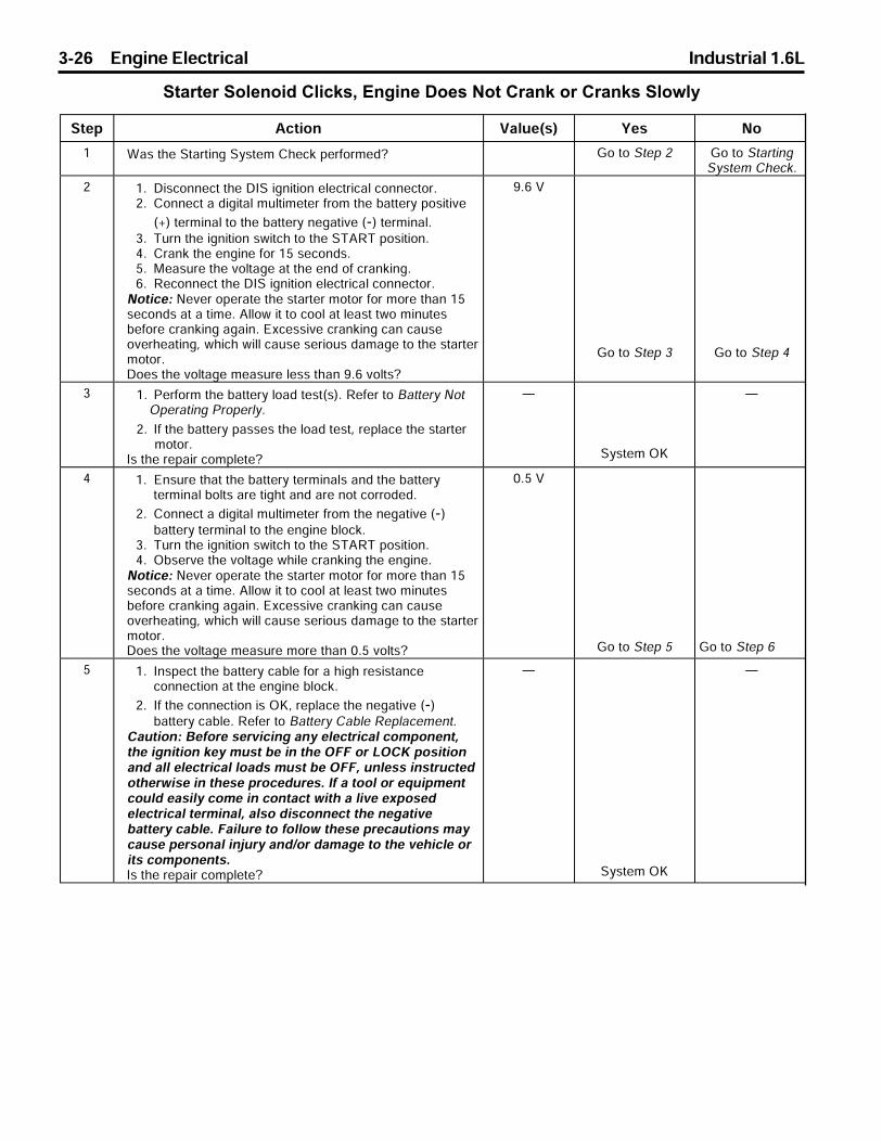
3-26 Engine Electrical Industrial 1.6L
Starter Solenoid Clicks, Engine Does Not Crank or Cranks Slowly
q¯¤ _¢¯¨¬« t ©°¤F®G w¤® l¬
O u ®>¯§¤>q¯ �¯¨«¦>q´®¯¤ª>a§¤¢�>¤�¥¬�ª¤£] e¬>¯¬>q¯¤>P e¬>¯¬>q¯ �¯¨«¦q´®¯¤ª>a§¤¢�L
P OL b¨®¢¬««¤¢¯>¯§¤>bgq>¨¦«¨¯¨¬«>¤©¤¢¯�¨¢ ©>¢¬««¤¢¯¬�LPL a¬««¤¢¯> >£¨¦¨¯ ©>ª°©¯¨ª¤¯¤�>¥�¬ª>¯§¤>¡ ¯¯¤�´>¬®¨¯¨±¤
FIG>¯¤�ª¨« ©>¯¬>¯§¤>¡ ¯¯¤�´>«¤¦ ¯¨±¤>FKG>¯¤�ª¨« ©LQL r°�«>¯§¤>¨¦«¨¯¨¬«>®²¨¯¢§>¯¬>¯§¤>qr_pr>¬®¨¯¨¬«LRL a� «�>¯§¤>¤«¦¨«¤>¥¬�>OS>®¤¢¬«£®LSL k¤ ®°�¤>¯§¤>±¬©¯ ¦¤> ¯>¯§¤>¤«£>¬¥>¢� «�¨«¦LTL p¤¢¬««¤¢¯>¯§¤>bgq>¨¦«¨¯¨¬«>¤©¤¢¯�¨¢ ©>¢¬««¤¢¯¬�L
l¬¯¨¢¤X>l¤±¤�>¬¤� ¯¤>¯§¤>®¯ �¯¤�>ª¬¯¬�>¥¬�>ª¬�¤>¯§ «>OS®¤¢¬«£®> ¯> >¯¨ª¤L>_©©¬²>¨¯>¯¬>¢¬¬©> ¯>©¤ ®¯>¯²¬>ª¨«°¯¤®¡¤¥¬�¤>¢� «�¨«¦> ¦ ¨«L>c³¢¤®®¨±¤>¢� «�¨«¦>¢ «>¢ °®¤¬±¤�§¤ ¯¨«¦J>²§¨¢§>²¨©©>¢ °®¤>®¤�¨¬°®>£ ª ¦¤>¯¬>¯§¤>®¯ �¯¤�ª¬¯¬�Lb¬¤®>¯§¤>±¬©¯ ¦¤>ª¤ ®°�¤>©¤®®>¯§ «>WLT>±¬©¯®]
WLT>t
e¬>¯¬>q¯¤>Q e¬>¯¬>q¯¤>R
Q OL n¤�¥¬�ª>¯§¤>¡ ¯¯¤�´>©¬ £>¯¤®¯F®GL>p¤¥¤�>¯¬>` ¯¯¤�´>l¬¯m¤� ¯¨«¦>n�¬¤�©´L
PL g¥>¯§¤>¡ ¯¯¤�´> ®®¤®>¯§¤>©¬ £>¯¤®¯J>�¤© ¢¤>¯§¤>®¯ �¯¤�ª¬¯¬�L
g®>¯§¤>�¤ ¨�>¢¬ª©¤¯¤]
Å
q´®¯¤ª>mi
Å
R OL c«®°�¤>¯§ ¯>¯§¤>¡ ¯¯¤�´>¯¤�ª¨« ©®> «£>¯§¤>¡ ¯¯¤�´¯¤�ª¨« ©>¡¬©¯®> �¤>¯¨¦§¯> «£> �¤>«¬¯>¢¬��¬£¤£L
PL a¬««¤¢¯> >£¨¦¨¯ ©>ª°©¯¨ª¤¯¤�>¥�¬ª>¯§¤>«¤¦ ¯¨±¤>FKG¡ ¯¯¤�´>¯¤�ª¨« ©>¯¬>¯§¤>¤«¦¨«¤>¡©¬¢�L
QL r°�«>¯§¤>¨¦«¨¯¨¬«>®²¨¯¢§>¯¬>¯§¤>qr_pr>¬®¨¯¨¬«LRL m¡®¤�±¤>¯§¤>±¬©¯ ¦¤>²§¨©¤>¢� «�¨«¦>¯§¤>¤«¦¨«¤L
l¬¯¨¢¤X>l¤±¤�>¬¤� ¯¤>¯§¤>®¯ �¯¤�>ª¬¯¬�>¥¬�>ª¬�¤>¯§ «>OS®¤¢¬«£®> ¯> >¯¨ª¤L>_©©¬²>¨¯>¯¬>¢¬¬©> ¯>©¤ ®¯>¯²¬>ª¨«°¯¤®¡¤¥¬�¤>¢� «�¨«¦> ¦ ¨«L>c³¢¤®®¨±¤>¢� «�¨«¦>¢ «>¢ °®¤¬±¤�§¤ ¯¨«¦J>²§¨¢§>²¨©©>¢ °®¤>®¤�¨¬°®>£ ª ¦¤>¯¬>¯§¤>®¯ �¯¤�ª¬¯¬�Lb¬¤®>¯§¤>±¬©¯ ¦¤>ª¤ ®°�¤>ª¬�¤>¯§ «>NLS>±¬©¯®]
NLS>t
e¬>¯¬>q¯¤>S e¬>¯¬>q¯¤>T
S OL g«®¤¢¯>¯§¤>¡ ¯¯¤�´>¢ ¡©¤>¥¬�> >§¨¦§>�¤®¨®¯ «¢¤¢¬««¤¢¯¨¬«> ¯>¯§¤>¤«¦¨«¤>¡©¬¢�L
PL g¥>¯§¤>¢¬««¤¢¯¨¬«>¨®>miJ>�¤© ¢¤>¯§¤>«¤¦ ¯¨±¤>FKG¡ ¯¯¤�´>¢ ¡©¤L>p¤¥¤�>¯¬>` ¯¯¤�´>a ¡©¤>p¤© ¢¤ª¤«¯L
a °¯¨¬«X>`¤¥¬�¤>®¤�±¨¢¨«¦> «´>¤©¤¢¯�¨¢ ©>¢¬ª¬«¤«¯J¯§¤>¨¦«¨¯¨¬«>�¤´>ª°®¯>¡¤>¨«>¯§¤>mdd>¬�>jmai>¬®¨¯¨¬« «£> ©©>¤©¤¢¯�¨¢ ©>©¬ £®>ª°®¯>¡¤>mddJ>°«©¤®®>¨«®¯�°¢¯¤£¬¯§¤�²¨®¤>¨«>¯§¤®¤>�¬¢¤£°�¤®L>g¥> >¯¬¬©>¬�>¤%°¨ª¤«¯¢¬°©£>¤ ®¨©´>¢¬ª¤>¨«>¢¬«¯ ¢¯>²¨¯§> >©¨±¤>¤³¬®¤£¤©¤¢¯�¨¢ ©>¯¤�ª¨« ©J> ©®¬>£¨®¢¬««¤¢¯>¯§¤>«¤¦ ¯¨±¤¡ ¯¯¤�´>¢ ¡©¤L>d ¨©°�¤>¯¬>¥¬©©¬²>¯§¤®¤>�¤¢ °¯¨¬«®>ª ´¢ °®¤>¤�®¬« ©>¨«&°�´> «£M¬�>£ ª ¦¤>¯¬>¯§¤>±¤§¨¢©¤>¬�¨¯®>¢¬ª¬«¤«¯®Lg®>¯§¤>�¤ ¨�>¢¬ª©¤¯¤]
Å
q´®¯¤ª>mi
Å

Industrial 1.6L Engine Electrical 3-27
Starter Solenoid Clicks, Engine Does Not Crank or Cranks Slowly (cont�d)q¯¤ _¢¯¨¬« t ©°¤F®G w¤® l¬
T OL b¨®¢¬««¤¢¯>¯§¤>bgq>¨¦«¨¯¨¬«>¤©¤¢¯�¨¢ ©>¢¬««¤¢¯¬�LPL a¬««¤¢¯> >£¨¦¨¯ ©>ª°©¯¨ª¤¯¤�>¥�¬ª>¯§¤>¬®¨¯¨±¤>FIG
¡ ¯¯¤�´>¯¤�ª¨« ©>¯¬>®¯ �¯¤�>®¬©¤«¬¨£>¯¤�ª¨« ©>`LQL r°�«>¯§¤>¨¦«¨¯¨¬«>®²¨¯¢§>¯¬>¯§¤>qr_pr>¬®¨¯¨¬«LRL m¡®¤�±¤>¯§¤>±¬©¯ ¦¤>²§¨©¤>¢� «�¨«¦LSL p¤¢¬««¤¢¯>¯§¤>bgq>¨¦«¨¯¨¬«>¤©¤¢¯�¨¢ ©>¢¬««¤¢¯¬�L
l¬¯¨¢¤X>l¤±¤�>¬¤� ¯¤>¯§¤>®¯ �¯¤�>ª¬¯¬�>¥¬�>ª¬�¤>¯§ «>OS®¤¢¬«£®> ¯> >¯¨ª¤L>_©©¬²>¨¯>¯¬>¢¬¬©> ¯>©¤ ®¯>¯²¬>ª¨«°¯¤®¡¤¥¬�¤>¢� «�¨«¦> ¦ ¨«L>c³¢¤®®¨±¤>¢� «�¨«¦>¢ «>¢ °®¤¬±¤�§¤ ¯¨«¦J>²§¨¢§>²¨©©>¢ °®¤>®¤�¨¬°®>£ ª ¦¤>¯¬>¯§¤>®¯ �¯¤�ª¬¯¬�Lb¬¤®>¯§¤>±¬©¯ ¦¤>ª¤ ®°�¤>ª¬�¤>¯§ «>NLS>±¬©¯®]
NLS>t
e¬>¯¬>q¯¤>U e¬>¯¬>q¯¤>V
U g«®¤¢¯>¯§¤>¡ ¯¯¤�´>¢ ¡©¤>¥¬�> >§¨¦§>�¤®¨®¯ «¢¤>¢¬««¤¢¯¨¬« ¯>¯§¤>®¯ �¯¤�>®¬©¤«¬¨£>`>¯¤�ª¨« ©L>g¥>¯§¤>¢¬««¤¢¯¨¬«>¨®>miJ�¤© ¢¤>¯§¤>¬®¨¯¨±¤>FIG>¡ ¯¯¤�´>¢ ¡©¤L>p¤¥¤�>¯¬>` ¯¯¤�´a ¡©¤>p¤© ¢¤ª¤«¯La °¯¨¬«X>`¤¥¬�¤>®¤�±¨¢¨«¦> «´>¤©¤¢¯�¨¢ ©>¢¬ª¬«¤«¯J¯§¤>¨¦«¨¯¨¬«>�¤´>ª°®¯>¡¤>¨«>¯§¤>mdd>¬�>jmai>¬®¨¯¨¬« «£> ©©>¤©¤¢¯�¨¢ ©>©¬ £®>ª°®¯>¡¤>mddJ>°«©¤®®>¨«®¯�°¢¯¤£¬¯§¤�²¨®¤>¨«>¯§¤®¤>�¬¢¤£°�¤®L>g¥> >¯¬¬©>¬�>¤%°¨ª¤«¯¢¬°©£>¤ ®¨©´>¢¬ª¤>¨«>¢¬«¯ ¢¯>²¨¯§> >©¨±¤>¤³¬®¤£¤©¤¢¯�¨¢ ©>¯¤�ª¨« ©J> ©®¬>£¨®¢¬««¤¢¯>¯§¤>«¤¦ ¯¨±¤¡ ¯¯¤�´>¢ ¡©¤L>d ¨©°�¤>¯¬>¥¬©©¬²>¯§¤®¤>�¤¢ °¯¨¬«®>ª ´¢ °®¤>¤�®¬« ©>¨«&°�´> «£M¬�>£ ª ¦¤>¯¬>¯§¤>±¤§¨¢©¤>¬�¨¯®>¢¬ª¬«¤«¯®Lg®>¯§¤>�¤ ¨�>¢¬ª©¤¯¤]
Å
q´®¯¤ª>mi
Å
V p¤© ¢¤>¯§¤>®¯ �¯¤�>ª¬¯¬�L>p¤¥¤�>¯¬>q¯ �¯¤�>k¬¯¬�p¤© ¢¤ª¤«¯Lg®>¯§¤>�¤ ¨�>¢¬ª©¤¯¤]
Å
q´®¯¤ª>mi
Å

3-28 Engine Electrical Industrial 1.6L
Spark Plug Wires Not Operating Properly1. Check the routing of the wires, Improper routing
can cause cross-firing.
2. Check each wire for any signs of cracks or splitsin the wire.
3. Inspect each boot for signs of tears, piercing, arcthrough, or carbon tracking. If the boot needs tobe replaced, twist it a half turn in each direction tobreak the seal before pulling on the boot todisconnect the wire.
Spark Plug Wire Resistance Test
Tools Required
J 39200 Digital Multimeter or Equivalent
1. Disconnect both ends of the wire that you wish tocheck.
Important: Ensure that the wire terminals areclean before proceeding.
2. Connect an ohmmeter lead to each end of thespark plug wire.
3. Gently twist the wire while observing the
ohmmeter reading.
4. If the ohmmeter reads above 30,000 ohms, nomatter how long the wire is, or fluctuates from
infinity to any value, replace the wire.
Spark Plug Wire Routing
Wire routing must be kept intact during service andfollowed exactly when wires have been disconnectedor when replacement of the wires becomes neces-sary. Failure to route the wires can result in cross-firing of the spark plugs or shorting of the wires toground. The correct routing of the spark plug wires isshown in the illustration.
80363004

Industrial 1.6L Engine Electrical 3-29
REPAIR INSTRUCTIONSBattery Cable ReplacementNotice: Always turn the ignition switch OFF when connecting or disconnecting batteries, battery chargers, or
jumper cables. Failure to do so may damage the electronic control unit or other electrical components.
Removal Procedure
Important: Whenever battery cables are replaced, always use a replacement cable that is the same type, diameter,and length. Always route the replacement cable in the same manner as the original cable. Always disconnect thenegative (-) cable from the battery first.
Caution: Refer to Battery Cautions on page 3-9.
1. Remove the negative (-) battery cable from the battery.
2. Remove the positive (+) battery cable from the battery.
3. Remove the battery cable routing ties, if applicable.
4. Remove the starter solenoid nut and the positive (+) battery cable.
5. Remove the bolt and the negative (-) battery cable from the engine block.
Installation Procedure
Caution: Refer to Battery Cautions on page 3-9.
Notice: When installing the positive battery cable to the starter solenoid, the inner nut on the solenoid battery terminalmust be tightened before the battery cable and the other leads are installed in the equipment. Failure to do so willresult in damage to the solenoid terminal and/or the solenoid.
Notice: Refer to Fastener Notice on page 3-2.
1. Install the positive (+) battery cable to the starter solenoid with the nut.
Tighten
Tighten the battery positive (+) cable starter solenoid nut to 16 N•m (12 lb ft).
2. Install the negative (-) battery cable to the engine block or cylinder head with the bolt.
Tighten
Tighten the battery negative cable bolt to 40 N•m (30 lb ft).
3. Install the positive (+) battery cable to the battery.
Tighten
Tighten the battery side terminal bolts (if applicable) to 12 N•m (106 lb in).
Tighten the top terminal nuts (if applicable) to 18 N•m (13 lb ft).
4. Install the negative (-) battery cable to the battery.
Tighten
Tighten the battery side terminal bolts (if applicable) to 12 N•m (106 lb in).
Tighten the top terminal nuts (if applicable) to 18 N•m (13 lb ft).
5. Install the battery cable routing ties, if applicable.

3-30 Engine Electrical Industrial 1.6L
Battery Charging
Basic Rules
When charging the battery, follow these basic rules:• Use a charger with an end of charge voltage of
16.0 volts. The charger should have a voltmeterthat is accurate within 1 percent.
• Ambient temperature should be 15-38°C (60-100°F). An extremely cold battery may notaccept measurable current after several hoursof charging.
• The charging area should be well ventilated.On batteries with a built-in hydrometer:
• Do not charge the battery if the built–inhydrometer is clear or light yellow (3). If cranking problems exist, replace the battery.
• Do not charge a battery that seems to befrozen. Replace the frozen battery.
• A battery with a green dot showing in thehydrometer (1) does not require chargingunless the battery has been discharged, suchas from cranking.
Charging Procedure
Caution: Refer to Battery Cautions on page 3-9.
Notice: Always turn the ignition OFF when connectingor disconnecting battery cables, battery chargers, orjumper cables. Failing to do so may damage theElectronic Control Module (ECU) or other electroniccomponents.
Important: Tighten the adapters against the leadterminals of the battery in order to keep the resistancebetween the adapters and the battery terminals to aminimum.
1. Make sure all connections to the charger are cleanand tight. When charging side terminal batteriesout of the equipment, install a pair of GM P/N12303040 adapters.
Important: Do not use the charger settings for jump–starting equipment in order to charge the battery.
2. Set the charger for 12–volt batteries that gives thehighest charge rate.
NOTE: On batteries with a built in hydrometer,charge the battery until the green dot (1) appears.
• Check the battery periodically while charging. • Lightly tap the hydrometer on top in order to
dislodge any air bubbles that may prevent acorrect indication.
3. Discontinue charging, or reduce the charging rate,if the following apply:
• The battery feels hot, above 52°C (125°F) • Violent gassing or spewing of electrolyte
through the vent holesAfter charging, test the battery. Refer to Battery NotOperating Properly and Battery Electrical Drain/Parasitic Load.
181056
42433

3-16 Engine Electrical Industrial 1.6L
q¯¤ _¢¯¨¬« t ©°¤F®G w¤® l¬
QQ gª¬�¯ «¯X>r¤ª¤� ¯°�¤>¢¬ª¤«® ¯¨¬«>¨®>¬«©´>«¤¢¤®® �´²§¤«>¯§¤>¯¤®¯¤�>£¤¯¤¢¯®>¯§ ¯>¯§¤>¡ ¯¯¤�´>¯¤ª¤� ¯°�¤>ª ´ ¥¥¤¢¯>¯§¤>�¤®°©¯®>¬¥>¯§¤>¯¤®¯L
OL s®¤>¯§¤>®¢�¬©©>�¤´®>¯¬>¨«£¨¢ ¯¤>²§¤¯§¤�>¯§¤>¨«¯¤�« ©¯¤ª¤� ¯°�¤>¬¥>¯§¤>¡ ¯¯¤�´>¨®> ¡¬±¤>¬�>¡¤©¬²>N_aFQP_dGL>s®¤>¯§¤>¯¤ª¤� ¯°�¤>¬¥>¯§¤>¡ ¯¯¤�´>¯¬>²§¨¢§¯§¤>¡ ¯¯¤�´>§ ®>¡¤¤«>¤³¬®¤£>¥¬�>¯§¤> ®¯>®¤±¤� ©§¬°�®>¨«>¬�£¤�>¯¬>¤®¯¨ª ¯¤>¯§¤>¯¤ª¤� ¯°�¤L
PL n°®§>¯§¤>clrcp>�¤´Lr§¤>¯¤®¯¤�>²¨©©>¡�¨¤¥©´>£¨®© ´>¯§¤>pcrcqrgle>ª¤®® ¦¤ «£>¯§¤>aa_>� ¯¨«¦>®¤©¤¢¯¤£>¥¬�>¯§¤>¯¤®¯L>r§¤>¯¤®¯>�¤®°©¯®²¨©©>¯§¤«>®§¬²>¬«>¯§¤>£¨®© ´Lb¬>¯§¤>¯¤®¯>�¤®°©¯®>®§¬²>¬«>¯§¤>£¨®© ´]
Å
e¬>¯¬>q¯¤>OR e¬>¯¬>q¯¤>QU
QR OL r§¤>¯¤®¯¤�>£¤¯¤¢¯®>¯§ ¯> «>¤©¤¢¯�¨¢ ©>©¬ £>¨®>�¤®¤«¯F®°¢§> ®> >©¨¦§¯>¨®>¬«>¬�>¯§¤>¨¦«¨¯¨¬«>�¤´>¨®>«¬¯>¨«>¯§¤mdd>¬®¨¯¨¬«GL
PL r°�«>mdd> ©©>¬¥>¯§¤>®´®¯¤ª>¤©¤¢¯�¨¢ ©>©¬ £®L_�¤> ©©>¬¥>¯§¤>®´®¯¤ª>¤©¤¢¯�¨¢ ©>©¬ £®>mdd]
Å
e¬>¯¬>q¯¤>QS
Å
QS r§¤>h>RPNNN> °¯¬ª ¯¨¢ ©©´>�¤¯¤®¯®>¯§¤>¡ ¯¯¤�´L>_pcrcqrgle>ª¤®® ¦¤> «£>qwqrck>lmgqc>ª¤®® ¦¤>¬«¯§¤>£¨®© ´> ©¯¤�« ¯¤®>°>¯¬>S>Fd¨±¤G>ª¨«°¯¤®>²§¨©¤> ©©¢¨�¢°¨¯®>¬²¤�>£¬²«L>r§¤>¯¤®¯>�¤®°©¯®>²¨©©>¯§¤«>£¨®© ´>¬«¯§¤>¯¤®¯¤�L_�¤>¯§¤>¯¤®¯>�¤®°©¯®>£¨®© ´¤£>¬«>¯§¤>¯¤®¯¤�]
Å
e¬>¯¬>q¯¤>OR e¬>¯¬>q¯¤>QT
QT _«>°«£¤¯¤¢¯¤£>©¬ £>¬�> � ®¨¯¨¢>£� ¨«>¢ «>¢ °®¤>¯§¤ ©¯¤�« ¯¨«¦>pcrcqrgle> «£>qwqrck>lmgqc>ª¤®® ¦¤®¯¬>¢¬«¯¨«°¤>¥¬�>ª¬�¤>¯§ «>S>Fd¨±¤G>ª¨«°¯¤®L
OL b¨®¢¬««¤¢¯>¯§¤>h>RPNNN>¯¤®¯¤�LPL c©¨ª¨« ¯¤> ©©>¤©¤¢¯�¨¢ ©> � ®¨¯¨¢>£� ¨«®L>p¤¥¤�>¯¬>` ¯¯¤�´
c©¤¢¯�¨¢ ©>b� ¨«Mn � ®¨¯¨¢>j¬ £L_�¤> ©©>¤©¤¢¯�¨¢ ©>©¬ £®> «£> � ®¨¯¨¢>£� ¨«®>¤©¨ª¨« ¯¤£]
Å
e¬>¯¬>q¯¤>P
Å
QU _>h>RPNNN>�¬¡©¤ª>¨®>¨«£¨¢ ¯¤£L>g«®¤¢¯>¯§¤>¯¤®¯¤�>¥¬�¢¬��¤¢¯>¬¤� ¯¨¬«Lg®>¯§¤>¯¤®¯¤�>¬¤� ¯¨«¦>�¬¤�©´]
Å
e¬>¯¬>q¯¤>P e¬>¯¬>q¯¤>QV
QV p¤ ¨�>¬�>�¤© ¢¤>¯§¤>¯¤®¯¤�L>g®>¯§¤> ¢¯¨¬«>¢¬ª©¤¯¤] Å e¬>¯¬>q¯¤>O Å
QW _>�¬¡©¤ª>¤³¨®¯®>²¨¯§>¯§¤>¡ ¯¯¤�´j®>¡°¨©¯^¨«>§´£�¬ª¤¯¤�>F¨¥ ©¨¢ ¡©¤GL>p¤© ¢¤>¯§¤>¡ ¯¯¤�´L>p¤¥¤�>¯¬>` ¯¯¤�´p¤© ¢¤ª¤«¯Lg®>¯§¤> ¢¯¨¬«>¢¬ª©¤¯¤]
Å
q´®¯¤ª>mi
Å
Battery Not Operating Properly (cont�d)
Battery Electrical Drain/Parasitic Load
Current Drain TestIf the equipment exhibits a low or dead battery after anovernight period, or discharges over a period of 2 or 3days and no cause is evident, the electrical systemshould be checked for an excessive electrical drain.The cause of the excessive unintended current drain isreferred to as a parasitic load. One or more on–boardsolid–state control modules, such as the ECU, may atsome time exhibit a failure mode that causes a highparasitic drain on the equipment’s battery. Anothersource of parasitic drain could be an unnoticed loadwhich remains on at all times.Testing for a parasitic drain requires a special toolbecause the excessive current drain may not occur
after the battery is disconnected to install an ammeter.Cycling the ignition key to the RUN and then to the OFFposition may cause such a drain to recur, but there maybe drains that will not recur unless the equipmentsystems are reactivated in a use test. The ignitionswitch must not be rotated to the START position withan ammeter installed between the battery terminal andthe battery cable, but the special tool enables theequipment to be run to assure that all equipmentsystems are ready for testing.
Tools Required• J 38758 Draw Test Switch• J 39200 Digital Multimeter, or equivalent

Industrial 1.6L Engine Electrical 3-17
Notice: Always turn the ignition switch OFF whenconnecting or disconnecting batteries, battery charg-ers, or jumper cables. Failure to do so may damagethe electronic control unit or other electricalcomponents.
1. Disconnect the negative battery cable.
2. Ensure that the ignition switch is OFF, andthat all electrical accessories are OFF.
3. Install the male end of the J 38758 to the negativebattery terminal.
4. Turn the J 38758 test switch to the OFF position.
5. Connect the negative battery cable to the femaleend of the J 38758 test switch.
6. Turn the J 38758 test switch to the ON position.
Notice: Do not turn the parasitic draw test switch to theOFF position with the engine running. Damage willoccur to the equipment’s electrical system.
7. Test the electrical system by running the engineand operating the equipment.
8. Turn the ignition switch to the LOCK position andremove the key. Turn all electrical accessories off.
9. In order to avoid a false reading, wait 15 minutesfor all components to power down before continu-ing this test.
10. Before connecting the ammeter, use the followingprocedure to determine whether or not the currentdrain is less than 10 amps:
10.1. Connect a jumper wire with an in–line 10-amp fuse or circuit breaker to the termi-nals of the J 38758 test switch.
10.2. Turn the J 38758 test switch to the OFFposition.
10.3. Wait 10 seconds.
11. If the fuse in the jumper wire does not blow, turnthe J 38758 test switch ON, set the J 39200 to the10–amp scale and connect the digital multimeterto the J 38758 test switch, and then remove thejumper wire. If current is greater than 10 amps,use a test lamp instead of an ammeter.
Important: Always turn the J 38758 test switch to theON position between tests. The ON position allowscurrent to flow through the battery cable. If the testswitch is left in the OFF position between tests, theammeter could be damaged due to accidental over-loading.
12. Remove the fuses one at a time, and install eachone after it is tested. Perform the following stepseach time a fuse is removed:
12.1. Turn the test switch to the OFF positionwhich forces all current to flow through themeter.
12.2. Wait at least 60 seconds. Check thecurrent reading. If the reading is at orbelow 2 amps, turn the test switch to theON position in order to maintain continuityin the electrical system while switching tothe 2 amp scale for a more accuratereading. Turn the test switch to the ONposition between tests.
12.3. The parasitic draw is typically under 60milliamperes. If the ammeter drops to anacceptable reading after a fuse is re-moved, the circuit causing the drain hasbeen identified.
12.4. Install the fuse for the circuit which iscausing the excessive drain. Using theschematic as a guide, disconnect thecomponents of the faulty circuit one at atime until the faulty component is located.
13. When the cause of excessive current draw has been located and repaired, remove the current drain test switch and connect the negative battery cable to the negative battery terminal.
314656

3-18 Engine Electrical Industrial 1.6L
Battery Hydrometer Displays Dark orYellow DotThe maintenance–free battery has a built–in hydrom-eter which consists of a ball floating in the electrolyte.The hydrometer is temperature–compensated. Thecolor of the hydrometer indicates the condition of thebattery.
• A green dot appearing on the hydrometermeans that the battery is ready for testing.
• A dark hydrometer with no green visible meansthat the battery has a low charge.
Refer to Charging System Check or BatteryElectrical Drain/Parasitic Load.
• A clear or light yellow color means thatthe battery fluid level is below the bottom of thehydrometer. Replace the battery if its conditionaffects the cranking system. A low fluid levelcan be caused by any of the followingconditions:
- An excessive charge - Tipping the battery - A faulty charging system. Refer to Charging System Check.
Battery Is Undercharged or Overcharged
q¯¤ _¢¯¨¬« t ©°¤F®G w¤® l¬
O OL b¨®¢¬««¤¢¯>¯§¤>¦¤«¤� ¯¬�>¢¬««¤¢¯¬�LPL n�¬¡¤>¯§¤>¦¤«¤� ¯¬�>¢¬««¤¢¯¬�>²¨¯§> >£¨¦¨¯ ©
ª°©¯¨ª¤¯¤�>¥�¬ª>¯§¤>¦¤«¤� ¯¬�>`_r>¯¤�ª¨« ©>¯¬>¦�¬°«£LQL k¤ ®°�¤>¯§¤>±¬©¯ ¦¤L
b¬¤®>¯§¤>±¬©¯ ¦¤>ª¤ ®°�¤>©¤®®>¯§ «>ON>±¬©¯®]
ON>t
e¬>¯¬>q¯¤>P e¬>¯¬>q¯¤>Q
P j¬¢ ¯¤> «£>�¤ ¨�>¯§¤>¬¤«>¨«>¯§¤>²¨�¤>¡¤¯²¤¤«>¯§¤>®¯ �¯¤�®¬©¤«¬¨£>q>¯¤�ª¨« ©> «£>¯§¤>¦¤«¤� ¯¬�>`_r>¯¤�ª¨« ©Lg®>¯§¤>�¤ ¨�>¢¬ª©¤¯¤]
Å
q´®¯¤ª>mi
Å
Q OL n�¬¡¤>¯§¤>¦¤«¤� ¯¬�>¢¬««¤¢¯¬�>²¨¯§> >£¨¦¨¯ ©ª°©¯¨ª¤¯¤�>¥�¬ª>¢ ±¨¯´>q>¯¬>¦�¬°«£L
PL k¤ ®°�¤>¯§¤>±¬©¯ ¦¤Lb¬¤®>¯§¤>±¬©¯ ¦¤>ª¤ ®°�¤>©¤®®>¯§ «>ON>±¬©¯®]
ON>t
e¬>¯¬>q¯¤>R e¬>¯¬>q¯¤>S
R j¬¢ ¯¤> «£>�¤ ¨�>¯§¤>¬¤«>¨«>¯§¤>pcb>²¨�¤>¡¤¯²¤¤«>¯§¤¦¤«¤� ¯¬�>`_r>¯¤�ª¨« ©> «£>¦¤«¤� ¯¬�>¢¬««¤¢¯¬�>¢ ±¨¯´>qLg®>¯§¤>�¤ ¨�>¢¬ª©¤¯¤]
Å
q´®¯¤ª>mi
Å
S OL r°�«>¯§¤>¨¦«¨¯¨¬«>®²¨¯¢§>¯¬>¯§¤>psl>¬®¨¯¨¬«LPL n�¬¡¤>¯§¤>¦¤«¤� ¯¬�>¢¬««¤¢¯¬�>²¨¯§> >£¨¦¨¯ ©
ª°©¯¨ª¤¯¤�>¥�¬ª>¢ ±¨¯´>g>¯¬>¦�¬°«£LLQL k¤ ®°�¤>¯§¤>±¬©¯ ¦¤L
b¬¤®>¯§¤>±¬©¯ ¦¤>ª¤ ®°�¤>©¤®®>¯§ «>ON>±¬©¯®]
ON>t
e¬>¯¬>q¯¤>T e¬>¯¬>q¯¤>U
T j¬¢ ¯¤> «£>�¤ ¨�>¯§¤>¬¤«>¨«>¯§¤>pcb>²¨�¤>¡¤¯²¤¤«>¯§¤¨¦«¨¯¨¬«>®²¨¯¢§>¯¤�ª¨« ©>g> «£>¦¤«¤� ¯¬�>¢¬««¤¢¯¬�>¢ ±¨¯´>gLg®>¯§¤>�¤ ¨�>¢¬ª©¤¯¤]
Å
q´®¯¤ª>mi
Å
U OL r°�«>¯§¤>¨¦«¨¯¨¬«>®²¨¯¢§>¯¬>¯§¤>mdd>¬®¨¯¨¬«LPL a¬««¤¢¯>¯§¤>¦¤«¤� ¯¬�>¢¬««¤¢¯¬�LQL q¯ �¯>¯§¤>¤«¦¨«¤LRL p°«>¯§¤>¤«¦¨«¤> ¯>¥ ®¯>¨£©¤LSL n�¬¡¤>¯§¤>¡ ¯¯¤�´>²¨¯§> >£¨¦¨¯ ©>ª°©¯¨ª¤¯¤�>¥�¬ª>¯§¤
¬®¨¯¨±¤>FIG>¯¤�ª¨« ©>¯¬>¯§¤>«¤¦ ¯¨±¤>FKG>¯¤�ª¨« ©LTL k¤ ®°�¤>¯§¤>±¬©¯ ¦¤L
b¬¤®>¯§¤>±¬©¯ ¦¤>ª¤ ®°�¤>¡¤¯²¤¤«>OQKOT>±¬©¯®]
OQKOT>t
e¬>¯¬>` ¯¯¤�´>l¬¯m¤� ¯¨«¦n�¬¤�©´L e¬>¯¬>q¯¤>V
V OL b¬> >e¤«¤� ¯¬�>`¤«¢§>r¤®¯L>p¤¥¤�>¯¬>e¤«¤� ¯¬�_®®¤ª¡©´>`¤«¢§>a§¤¢�L
PL g¥>¯§¤>¦¤«¤� ¯¬�>¨®>miJ>£¬> >¡ ¯¯¤�´>©¬ £>¯¤®¯L>p¤¥¤�>¯¬` ¯¯¤�´>l¬¯>m¤� ¯¨«¦>n�¬¤�©´L
g®>¯§¤>�¤ ¨�>¢¬ª©¤¯¤]
Å
q´®¯¤ª>mi
Å

Industrial 1.6L Engine Electrical 3-19
Engine Cranks/Cranks Slowly, But Does Not Start
q¯¤ _¢¯¨¬« t ©°¤F®G w¤® l¬
O s®¤> >£¨¦¨¯ ©>ª°©¯¨ª¤¯¤�>¯¬>ª¤ ®°�¤>¯§¤>±¬©¯ ¦¤>¬¥>¯§¤¡ ¯¯¤�´Lg®>¯§¤>±¬©¯ ¦¤>¦�¤ ¯¤�>¯§ «>¬�>¤&° ©>¯¬>¯§¤>®¤¢¨¥¨¤£>± ©°¤]
OP>t
e¬>¯¬>q¯¤>S e¬>¯¬>q¯¤>P
P OL c«®°�¤>¯§¤>¡ ¯¯¤�´>¯¤�ª¨« ©®> «£>¯¤�ª¨« ©>¡¬©¯®> �¤¥�¤¤>¥�¬ª>¢¬��¬®¨¬«L
PL a§ �¦¤>¯§¤>¡ ¯¯¤�´L>p¤¥¤�>¯¬>` ¯¯¤�´>a§ �¦¨«¦LQL b¨®¢¬««¤¢¯>¯§¤>bgq>¨¦«¨¯¨¬«>ª¬£°©¤>¢¬««¤¢¯¬�LRL _¯¯¤ª¯>¯¬>¢� «�>¯§¤>¤«¦¨«¤L
b¬¤®>¯§¤>¤«¦¨«¤>¢� «�>«¬�ª ©©´]
Å
e¬>¯¬>q¯¤>Q e¬>¯¬>q¯¤>S
Q OL a¬««¤¢¯>¯§¤>bgq>¨¦«¨¯¨¬«>ª¬£°©¤>¢¬««¤¢¯¬�LPL t¤�¨¥´>¯§ ¯>¯§¤>¢§ �¦¨«¦>®´®¯¤ª>¨®>¬¤� ¯¨«¦>¢¬��¤¢¯©´L
p¤¥¤�>¯¬>a§ �¦¨«¦>q´®¯¤ª>a§¤¢�Lg®>¯§¤>¢§ �¦¨«¦>®´®¯¤ª>mi]
Å
q´®¯¤ª>mi e¬>¯¬>q¯¤>R
R p¤ ¨�>¯§¤>¢§ �¦¨«¦>®´®¯¤ªLg®>¯§¤>�¤ ¨�>¢¬ª©¤¯¤]
Åq´®¯¤ª>mi
Å
S OL b¨®¢¬««¤¢¯>¯§¤>bgq>¨¦«¨¯¨¬«>ª¬£°©¤>¢¬««¤¢¯¬�L>b¬>«¬¯¢¬««¤¢¯>¯§¤>bgq>¨¦«¨¯¨¬«>ª¬£°©¤>¢¬««¤¢¯¬�>°«¯¨©> ©©¢� «�¨«¦>¯¤®¯®> �¤>¢¬ª©¤¯¤£L
PL r°�«>¯§¤>¨¦«¨¯¨¬«>®²¨¯¢§>¯¬>¯§¤>qr_pr>¬®¨¯¨¬«LQL s®¤> >h>QWPNN>bkk>¯¬>ª¤ ®°�¤>¯§¤>±¬©¯ ¦¤>¡¤¯²¤¤«
¯§¤>¡ ¯¯¤�´>¯¤�ª¨« ©®>²§¨©¤>¢� «�¨«¦>¯§¤>¤«¦¨«¤>¥¬�>OSF¥¨¥¯¤¤«G>®¤¢¬«£®L
l¬¯¨¢¤X>l¤±¤�>¬¤� ¯¤>¯§¤>®¯ �¯¤�>ª¬¯¬�>¥¬�>ª¬�¤>¯§ «>OS®¤¢¬«£®> ¯> >¯¨ª¤L>_©©¬²>¨¯>¯¬>¢¬¬©> ¯>©¤ ®¯>¯²¬>ª¨«°¯¤®¡¤¥¬�¤>¢� «�¨«¦> ¦ ¨«L>c³¢¤®®¨±¤>¢� «�¨«¦>¢ «>¢ °®¤¬±¤�§¤ ¯¨«¦J>²§¨¢§>²¨©©>¢ °®¤>®¤�¨¬°®>£ ª ¦¤>¯¬>¯§¤>®¯ �¯¤�ª¬¯¬�Lb¬¤®>¯§¤>±¬©¯ ¦¤>£�¬>¡¤©¬²>¯§¤>®¤¢¨¥¨¤£>± ©°¤>²§¨©¤>¯§¤®¯ �¯¤�>¨®>¢� «�¨«¦>¯§¤>¤«¦¨«¤]
WLS>t
e¬>¯¬>q¯¤>T e¬>¯¬>q¯¤>W
T j¬ £>¯¤®¯>¯§¤>¡ ¯¯¤�´L>p¤¥¤�>¯¬>` ¯¯¤�´>l¬¯>m¤� ¯¨«¦n�¬¤�©´Lg®>¯§¤>¡ ¯¯¤�´>mi]
Å
e¬>¯¬>q¯¤>V e¬>¯¬>q¯¤>U
U p¤© ¢¤>¯§¤>¡ ¯¯¤�´L>p¤¥¤�>¯¬>` ¯¯¤�´>p¤© ¢¤ª¤«¯Lg®>¯§¤>�¤ ¨�>¢¬ª©¤¯¤]
Åq´®¯¤ª>mi
Å
V p¤© ¢¤>¯§¤>®¯ �¯¤�>ª¬¯¬�L>p¤¥¤�>¯¬>q¯ �¯¤�>k¬¯¬�p¤© ¢¤ª¤«¯Lg®>¯§¤>�¤ ¨�>¢¬ª©¤¯¤]
Å
q´®¯¤ª>mi
Å
W s®¤> >£¨¦¨¯ ©>ª°©¯¨ª¤¯¤�>¯¬>ª¤ ®°�¤>¯§¤>±¬©¯ ¦¤>¡¤¯²¤¤«¯§¤>¡ ¯¯¤�´>«¤¦ ¯¨±¤>F^G>¯¤�ª¨« ©> «£>¯§¤>¤«¦¨«¤>¡©¬¢�>²§¨©¤¢� «�¨«¦>¯§¤>¤«¦¨«¤Ll¬¯¨¢¤X>l¤±¤�>¬¤� ¯¤>¯§¤>®¯ �¯¤�>ª¬¯¬�>¥¬�>ª¬�¤>¯§ «>OS®¤¢¬«£®> ¯> >¯¨ª¤L>_©©¬²>¨¯>¯¬>¢¬¬©> ¯>©¤ ®¯>¯²¬>ª¨«°¯¤®¡¤¥¬�¤>¢� «�¨«¦> ¦ ¨«L>c³¢¤®®¨±¤>¢� «�¨«¦>¢ «>¢ °®¤¬±¤�§¤ ¯¨«¦J>²§¨¢§>²¨©©>¢ °®¤>®¤�¨¬°®>£ ª ¦¤>¯¬>¯§¤>®¯ �¯¤�ª¬¯¬�Lg®>¯§¤>±¬©¯ ¦¤>¦�¤ ¯¤�>¯§ «>¯§¤>®¤¢¨¥¨¤£>± ©°¤]
NLS>t
e¬>¯¬>q¯¤>ON e¬>¯¬>q¯¤>OQ
ON OL g«®¤¢¯>¯§¤>¡ ¯¯¤�´> «£>«¤¦ ¯¨±¤>F^G>¡ ¯¯¤�´>¢ ¡©¤>¯¬£¤¯¤�ª¨«¤>¨¥>¯§¤�¤>¨®> >§¨¦§^�¤®¨®¯ «¢¤>¢¬««¤¢¯¨¬«> ¯¤¨¯§¤�>¤«£L
PL c«®°�¤>¯§ ¯>¯§¤�¤>¨®> >¢©¤ «>¢¬««¤¢¯¨¬«>¡¤¯²¤¤«>¯§¤®¯ �¯¤�>ª¬°«¯¨«¦>®°�¥ ¢¤> «£>¯§¤>¤«¦¨«¤>¡©¬¢�L
u ®> >§¨¦§^�¤®¨®¯ «¢¤>¢¬««¤¢¯¨¬«>¥¬°«£]
Å
e¬>¯¬>q¯¤>OO e¬>¯¬>q¯¤>OP
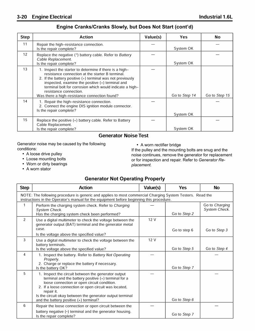
3-20 Engine Electrical Industrial 1.6L
Engine Cranks/Cranks Slowly, but Does Not Start (cont�d)
Generator Not Operating Properly
Generator noise may be caused by the followingconditions:
• A loose drive pulley• Loose mounting bolts• Worn or dirty bearings• A worn stator
• A worn rectifier bridgeIf the pulley and the mounting bolts are snug and thenoise continues, remove the generator for replacementor for inspection and repair. Refer to Generator Re-placement.
Generator Noise Test
q¯¤ _¢¯¨¬« t ©°¤F®G w¤® l¬
lmrcX>r§¤>¥¬©©¬²¨«¦>�¬¢¤£°�¤>¨®>¦¤«¤�¨¢> «£> ©¨¤®>¯¬>ª¬®¯>¢¬ªª¤�¢¨ ©>a§ �¦¨«¦>q´®¯¤ª>r¤®¯¤�®L>>p¤ £>¯§¤¨«®¯�°¢¯¨¬«®>¨«>¯§¤>m¤� ¯¬�E®>ª «° ©>¥¬�>¯§¤>¤&°¨ª¤«¯>¡¤¥¬�¤>¡¤¦¨««¨«¦>¯§¨®>�¬¢¤£°�¤L
O n¤�¥¬�ª>¯§¤>¢§ �¦¨«¦>®´®¯¤ª>¢§¤¢�L>p¤¥¤�>¯¬>a§ �¦¨«¦q´®¯¤ª>a§¤¢�Lf ®>¯§¤>¢§ �¦¨«¦>®´®¯¤ª>¢§¤¢�>¡¤¤«>¤�¥¬�ª¤£]
Å
e¬>¯¬>q¯¤>P
e¬>¯¬>a§ �¦¨«¦q´®¯¤ª>a§¤¢�L
P s®¤> >£¨¦¨¯ ©>ª°©¯¨ª¤¯¤�>¯¬>¢§¤¢�>¯§¤>±¬©¯ ¦¤>¡¤¯²¤¤«>¯§¤¦¤«¤� ¯¬�>¬°¯°¯>F`_rG>¯¤�ª¨« ©> «£>¯§¤>¦¤«¤� ¯¬�>ª¤¯ ©¢ ®¤L
g®>¯§¤>±¬©¯ ¦¤> ¡¬±¤>¯§¤>®¤¢¨¥¨¤£>± ©°¤]
OP>t
e¬>¯¬>®¯¤>T e¬>¯¬>q¯¤>Q
Q s®¤> >£¨¦¨¯ ©>ª°©¯¨ª¤¯¤�>¯¬>¢§¤¢�>¯§¤>±¬©¯ ¦¤>¡¤¯²¤¤«>¯§¤¡ ¯¯¤�´>¯¤�ª¨« ©®Lg®>¯§¤>±¬©¯ ¦¤> ¡¬±¤>¯§¤>®¤¢¨¥¨¤£>± ©°¤]
OP>t
e¬>¯¬>q¯¤>S e¬>¯¬>q¯¤>R
R OL g«®¤¢¯>¯§¤>¡ ¯¯¤�´L>p¤¥¤�>¯¬>` ¯¯¤�´>l¬¯>m¤� ¯¨«¦n�¬¤�©´L
PL a§ �¦¤>¬�>�¤© ¢¤>¯§¤>¡ ¯¯¤�´>¨¥>«¤¢¤®® �´Lg®>¯§¤>¡ ¯¯¤�´>mi]
Å
e¬>¯¬>q¯¤>U
Å
S OL g«®¤¢¯>¯§¤>¢¨�¢°¨¯>¡¤¯²¤¤«>¯§¤>¦¤«¤� ¯¬�>¬°¯°¯¯¤�ª¨« ©> «£>¯§¤>¡ ¯¯¤�´>¬®¨¯¨±¤>FIG>¯¤�ª¨« ©>¥¬�> ©¬¬®¤>¢¬««¤¢¯¨¬«>¬�>¬¤«>¢¨�¢°¨¯>¢¬«£¨¯¨¬«L
PL g¥> >©¬¬®¤>¢¬««¤¢¯¨¬«>¬�>¬¤«>¢¨�¢°¨¯>² ®>©¬¢ ¯¤£J�¤ ¨�>¨¯L
g®>¯§¤>¢¨�¢°¨¯>¬� ´>¡¤¯²¤¤«>¯§¤>¦¤«¤� ¯¬�>¬°¯°¯>¯¤�ª¨« © «£>¯§¤>¡ ¯¯¤�´>¬®¨¯¨±¤>FIG>¯¤�ª¨« ©]
Å
e¬>¯¬>q¯¤>T
Å
T p¤ ¨�>¯§¤>©¬¬®¤>¢¬««¤¢¯¨¬«>¬�>¬¤«>¢¨�¢°¨¯>¡¤¯²¤¤«>¯§¤
¡ ¯¯¤�´>«¤¦ ¯¨±¤>FKG>¯¤�ª¨« ©> «£>¯§¤>¦¤«¤� ¯¬�>§¬°®¨«¦Lg®>¯§¤>�¤ ¨�>¢¬ª©¤¯¤]
Å
e¬>¯¬>q¯¤>U
Å
q¯¤ _¢¯¨¬« t ©°¤F®G w¤® l¬
OO p¤ ¨�>¯§¤>§¨¦§^�¤®¨®¯ «¢¤>¢¬««¤¢¯¨¬«Lg®>¯§¤>�¤ ¨�>¢¬ª©¤¯¤]
Åq´®¯¤ª>mi
Å
OP p¤© ¢¤>¯§¤>«¤¦ ¯¨±¤>F*G>¡ ¯¯¤�´>¢ ¡©¤L>p¤¥¤�>¯¬>` ¯¯¤�´a ¡©¤>p¤© ¢¤ª¤«¯Lg®>¯§¤>�¤ ¨�>¢¬ª©¤¯¤]
Å
q´®¯¤ª>mi
Å
OQ OL g«®¤¢¯>¯§¤>®¯ �¯¤�>¯¬>£¤¯¤�ª¨«¤>¨¥>¯§¤�¤>¨®> >§¨¦§^�¤®¨®¯ «¢¤>¢¬««¤¢¯¨¬«> ¯>¯§¤>®¯ �¯¤�>`>¯¤�ª¨« ©L
PL g¥>¯§¤>¡ ¯¯¤�´>¬®¨¯¨±¤>FIG>¯¤�ª¨« ©>² ®>«¬¯>�¤±¨¬°®©´¨«®¤¢¯¤£J>¤³ ª¨«¤>¯§¤>¬®¨¯¨±¤>FIG>¯¤�ª¨« ©> «£¯¤�ª¨« ©>¡¬©¯>¥¬�>¢¬��¬®¨¬«>²§¨¢§>²¬°©£>¨«£¨¢ ¯¤> >§¨¦§^�¤®¨®¯ «¢¤>¢¬««¤¢¯¨¬«L
u ®>¯§¤�¤> >§¨¦§^�¤®¨®¯ «¢¤>¢¬««¤¢¯¨¬«>¥¬°«£]
Å
e¬>¯¬>q¯¤>OR e¬>¯¬>q¯¤>OS
OR OL p¤ ¨�>¯§¤>§¨¦§^�¤®¨®¯ «¢¤>¢¬««¤¢¯¨¬«LPL a¬««¤¢¯>¯§¤>¤«¦¨«¤>bgq>¨¦«¨¯¨¬«>ª¬£°©¤>¢¬««¤¢¯¬�L
g®>¯§¤>�¤ ¨�>¢¬ª©¤¯¤]
Å
q´®¯¤ª>mi
Å
OS p¤© ¢¤>¯§¤>¬®¨¯¨±¤>FIG>¡ ¯¯¤�´>¢ ¡©¤L>p¤¥¤�>¯¬>` ¯¯¤�´a ¡©¤>p¤© ¢¤ª¤«¯Lg®>¯§¤>�¤ ¨�>¢¬ª©¤¯¤]
Å
q´®¯¤ª>mi
Å

Industrial 1.6L Engine Electrical 3-31
Charging Time Required
The time required to charge a battery will vary. The time depends on the following factors:• Size of the battery - A completely discharged heavy–duty battery requires more than twice the recharging
time as a completely discharged light–duty battery.• Temperature - Colder batteries require more time to recharge.• Cold batteries accept only very low current at first during charging. The cold battery will
accept a higher charging rate as the battery warms.• Charger Capacity - A charger with higher amperage charges batteries in less time.• State–Of–Charge - A completely discharged battery requires more than twice as much charge as a one–half
charged battery.The electrolyte in a completely discharged battery is nearly pure water, so the electrolyte is a very poor conductor. Inthis condition, the battery accepts very low current at first. Later, as the charging current increases the acid content ofthe electrolyte, the charging current also increases.
Any battery discharged by parasitic current drain, and then allowed to stand in this condition for a period of time, maynot readily accept a charge. However, recharged long enough, many batteries will return to a usable condition.
Prolonged periods in a discharged state can result in permanent damage to the battery. This damage can accelerateunder changing temperatures. Batteries that are extremely discharged can freeze at temperatures as high as -7°C(20°F). This results in permanent damage.
Disconnect the negative battery cable of equipment that is not going to be in service within a 30–day period. This willremove the constant drain on the battery. This can prevent damage to the battery and recharge problems. If this is notpossible, recharge the battery every 30-45 days until the green dot is visible.

3-32 Engine Electrical Industrial 1.6L
Battery Charge Low or Completely Discharged
Tools Required
J 39200 Digital Multimeter (DMM), or Equivalent
Caution: Refer to Battery Cautions on page 3-9.
Notice: Always turn the ignition OFF when connecting or disconnecting battery cables, battery chargers, or jumpercables. Failing to do so may damage the Electronic Control Module (ECU) or other electronic components.
Important: Tighten the adapters against the lead terminals of the battery in order to keep the resistance between theadapters and the battery terminals to a minimum.
Use the following procedure in order to recharge a very low or completely discharged battery. Carefully follow theprocedure in order to avoid the replacement of a usable battery.
1. Measure the battery voltage at the battery terminals using the multimeter.• A reading of less than 11 volts indicates that the initial charging will be very low.• It could take some time before the battery accepts current in excess of a few milliamperes.
2. Set the battery charger on the high setting.
3. If necessary, disable the polarity protection circuitry.• This circuitry, available on most chargers, prevents charging unless the charger leads are properly connected
to the battery terminals.• A completely discharged battery may not have enough voltage to activate this circuitry, even though the leads
are properly connected, implying that the battery will not accept a charge.• Most chargers have an override or a bypass function so that the charger will turn ON and charge a low
voltage battery.
Important: If the charging current is not measurable at the end of the charging time, replace the battery.
If the charging current is measurable during the charging time, the battery is good.
The required battery charge time varies according to the voltage capabilities of the battery charger. Charging time atvarious voltages may be as follows:
• 16.0 volts or more - up to 4 hours• 14.0-15.9 volts - 8 hours• 13.9 volts or less - 16 hours
4. In order to determine the amount of hours the battery may need to be charged, the following calculation can bemade:• The reserve capacity rating on the battery label is the number of ampere–hours of charge required in order to
produce the green hydrometer dot.• After the meter on the charger starts to show current flow, note the number of amps being accepted.• Determine the reserve capacity of the battery. Refer to Battery Usage.• Divide the reserve capacity by the number of amps shown on the meter in order to determine how many
hours of charging is needed.
5. When the green dot appears in the hydrometer, discontinue charging.
6. If the green hydrometer dot is not visible after an ampere–hour charge equal to twice the reserve capacity rating,replace the battery. Refer to Battery Replacement.
7. After charging, load test the battery. Refer to Battery Not Operating Properly.
Battery Replacement
Removal Procedure
Caution: Refer to Battery Cautions on page 3-9.
Notice: Always turn the ignition OFF when connecting or disconnecting battery cables, battery chargers, or jumpercables. Failing to do so may damage the Electronic Control Module (ECU) or other electronic components.
1. Disconnect the negative cable from the negative battery terminal.
2. Disconnect the positive cable from the positive battery terminal.
3. Remove the battery hold–down retainers.
4. Remove the battery.
5. Inspect the battery for damage.
6. Inspect the battery cables and the connections.7. Inspect the carrier for damage or foreign objects. If damage is found, correct the cause.

Industrial 1.6L Engine Electrical 3-33
Battery Replacement - Continued
Installation Procedure
1. Install the battery into the carrier.
Notice: Refer to Fastener Notice on page 3-2.
2. Install the battery hold–down retainers or the top bars.
Tighten
Tighten the retainer bolt to 18 N•m (13 lb ft). Tighten the top bar nut to 10 N•m (89 lb in).
3. Install the positive (+) battery cable to the battery.
Tighten
Tighten the battery side terminal bolts (if applicable) to 12 N•m (106 lb in).
Tighten the top terminal nuts (if applicable) to 18 N•m (13 lb ft).
4. Install the negative (-) battery cable to the battery.
Tighten
Tighten the battery side terminal bolts (if applicable) to 12 N•m (106 lb in).
Tighten the top terminal nuts (if applicable) to 18 N•m (13 lb ft).
Jump Starting in Case of EmergencyDo not try to jump start equipment if you are unsure of the voltage or ground of the other equipment, or if the voltageand ground of the other equipment is different.
Be careful of the booster battery and the discharged battery when using jumper cables. Be careful in order to avoidcausing sparks.
Notice: To protect the electronic control module, do jump the battery with “Hot Shot” (over 14 V) charging aids. Donot disconnect the battery while the engine is running to verify charging system operation.
Jump Starting Procedure
Caution: Refer to Battery Cautions on page 3-9.
Notice: Always turn the ignition OFF when connecting or disconnecting battery cables, battery chargers, or jumpercables. Failing to do so may damage the Electronic Control Module (ECU) or other electronic components.
1. If equipped, check the built–in hydrometer. If the hydrometer is clear or light yellow (3), do not jump start thebattery. Replace the battery. Refer to Battery Replacement.
2. Ensure the jumper cables do not have loose or missing insulation.
3. Position the equipment with the booster (good) battery so that the jumper cables will reach, but DO NOT let theequipment touch.
4. Connect one jumper cable to the positive terminal of the booster battery and the positive terminal of the dis-charged equipment.
5. Attach one end of the other jumper cable to the negative terminal of the booster battery.
6. Attach the remaining end of the jumper cable to a solid ground at least 450 mm (18 in) from the booster battery.
7. Start the engine of the equipment with the booster battery. Turn off all electrical accessories.
8. Start the engine of the equipment with the discharged battery.
9. Disconnect the jumper cable from the ground.
10. Disconnect the other end of the jumper cable from the negative terminal of the booster battery.11. Remove the jumper cable connecting the positive terminals.

3-34 Engine Electrical Industrial 1.6L
Starter Motor Inspection
Cleaning Procedure
Notice: Do not use grease dissolving solvents for cleaning the overrunning clutch or armature. Solvents dissolve thegrease packed in the clutch and damage the armature and the field coil insulation.
Clean all starter motor parts with a soft cloth prior to testing.
Inspection Procedure
Inspection in the following steps refers to visual inspection of the starter motor parts and assemblies in order todetermine the serviceability of the parts.
1. Inspect all parts for cracks, distortion, or other structural damage. Replace parts and assemblies that arecracked, bent, or otherwise damaged.
2. Inspect the threaded parts for stripped, crossed, or otherwise damaged threads. Replace parts as necessary.• Replace the parts with thread damage that cannot be cleaned up using a suitable tap or die.• Replace any hardware items that have damaged threads.
3. Inspect the solenoid assembly for a cut or torn boot. If the boot is damaged, replace the solenoid assembly.
4. Inspect the clutch drive assembly. Replace the clutch drive assembly as necessary. Look for the followingdamage:• The pinion gear turns roughly or turns in both directions.• The pinion gear teeth are broken or show evidence of step wear.• The shift lever collar shows deep scoring or other damage.
Component Electrical Testing
Perform the following electrical tests in order to determine the serviceability of the starter assemblies.
1. Using an ohmmeter, check the windings of the solenoid assembly for continuity using the following procedure:• Check the resistance of the solenoid pull–in and hold–in windings in a series by measuring the resis
tance between the motor terminal and the solenoid case.• A resistance reading well above 1.95 ohms indicates a break or fault in the winding continuity.• A resistance reading well below 1.95 ohms indicates a short or ground in the winding circuit.• Replace the solenoid assembly if the resistance reading is extremely high or very low.
2. Check the armature for shorts, opens and grounds using the following procedure. Replace armature if it isshorted, grounded, or has any evidence of an open circuit.2.1. Rotate the armature in a growler.2.2. Hold a steel strip such as a hacksaw against the armature.2.3. If the steel strip vibrates in an area, a short is present.
− Using a self–powered test lamp or ohmmeter, check for continuity between the armature shaft and any point on the commutator. Continuity indicates a ground.
− Inspect the points where the armature conductors join the commutator for signs of arcing or burning. These signs indicate opens.
Armature Bearing Replacement
Notice: Ball bearings that are removed from the armature must be replaced with new bearings. The removal proce-dure causes internal damage to the bearings.
Removal Procedure
Remove the commutator end or drive end bearings from the armature assembly using a suitable bearing puller.
Installation Procedure
1. Install the new commutator end and/or drive end bearings to the armature assembly using a tube that bears onlyon the bearing inner race.
2. Press on the bearing until the inner race bottoms out against the shoulder of the armature shaft.

Industrial 1.6L Engine Electrical 3-35
Starter Motor Replacement
Removal Procedure
Notice: Never operate the starter motor more than 15seconds at a time without pausing to allow it to cool forat least 2 minutes. Overheating, caused by excessivecranking, will damage the starter motor.
Starter motors do not require lubrication except duringoverhaul.
Caution: Refer to Battery Cautions on page 3-8.
1. Disconnect the negative (-) battery cable.
2. Disconnect the wires and the positive (+) batterycable from the starter solenoid.
3. Remove the mounting bolt, stud and the washersthat hold the starter to the engine.
4. Remove the starter and shims (if present) from theengine.
5. Remove the starter shield, if equipped.
Installation Procedure1. Install the shield to the starter motor, if equipped.
2. Position the starter motor and shims (if used) onthe engine.
Notice: Refer to Fastener Notice on page 3-2.
3. Install the mounting bolt, stud, and washers.
Tighten
Tighten the starter bolt and stud to 25 N•m(18 lb ft).
3. Install the positive (+) battery cable and wires tothe starter solenoid with the nut.
Tighten• Tighten the battery positive (+) cable starter solenoid nut to 15 N•m (11 lb ft).• Tighten the S terminal nut to 6.5 N•m (55 lb in).
5. Install the negative (-) battery cable to the battery.
Tighten• Tighten the battery side terminal bolts (if applicable) to 12 N•m (106 lb in).
• Tighten the top terminal nuts (if applicable)
to 18 N•m (13 lb ft).
8036012
80363003
80363003

3-36 Engine Electrical Industrial 1.6L
Generator Replacement
Removal Procedure
The removal and installation instructions serve only asa guide. Additional operations may be required onsome equipment to remove other equipment in order togain access to the generator, the drive belt, and thebrackets.
Caution: Failure to observe Step 1 in this proce-dure may result in an injury from the live batterylead at the generator.
Caution: Refer to Battery Cautions on page 3-8.
1. Disconnect the negative (-) battery cable.
2. Disconnect the electrical connectors from thegenerator.
3. Disconnect the battery lead from the back of thegenerator.
4. Disconnect the generator ground wire.
5. Remove the drive belt. Refer to Drive Belt Re-placement in Engine Cooling.
6. Remove the upper generator mounting bolt.
7. Remove the lower generator mounting bolt andnut.
8. Remove the generator from the generator mounting bracket.
Installation Procedure
1. Install the generator into the generator mountingbracket.
Notice: Refer to Fastener Notice on page 3-2.
2. Install the generator mounting bolts.
Tighten• Tighten the top mounting bolt to 20 N•m (15 lb ft).• Tighten the bottom mounting bolt and nut to 35 N•m (26 lb ft).
3. Install the drive belt. Refer to Drive Belt Replace-ment in Engine Cooling.
4. Install the generator ground wire.
5. Connect the electrical connectors to the generator.
6. Connect the battery lead to the back of thegenerator.
Tighten
Tighten to battery terminal nut to 8 N•m (71 lb in).
7. Connect the negative (-) battery cable to thebattery.
Tighten
Tighten the battery side terminal bolts (if appli-
cable) to 12 N•m (106 lb in).
Tighten the top terminal nuts (if applicable) to 18
N•m (13 lb ft).
80363002
80363002

Industrial 1.6L Engine Electrical 3-37
DIS Ignition Module Replacement
Removal Procedure
1. Noting their positions, remove the spark plug wiresfrom the module.
2. Disconnect the engine wiring harness connector fromthe module.
3. Remove the three module mounting bolts.
4. Remove the module from the camshaft housing.
Installation Procedure
1. Position the module on the camshaft housing.
2. Install the three module mounting bolts.
Tighten
Tighten the mounting bolts to 8 N•m (71 lb in).
3. Connect the engine wiring harness connector tothe module.
4. Install the spark plug wires to the module in the samepositions noted during removal.
Setting Ignition Timing
The PSI 1.6L engine has a distributorless ignitionsystem (DIS). The ignition timing adjustments arecontrolled by the Electronic Control Unit, or ECU.
A timing indicator and timing marks are still visible atthe crankshaft pulley, but are not used to set or adjust
ignition timing.
Crankshaft Position (CKP) SensorReplacement
Removal Procedure
1. Disconnect the engine wiring harness connector fromthe crankshaft position sensor pigtail.
2. Remove the crankshaft position sensor pigtail fromthe camshaft housing cover bracket.
80363005
80363006
80363005
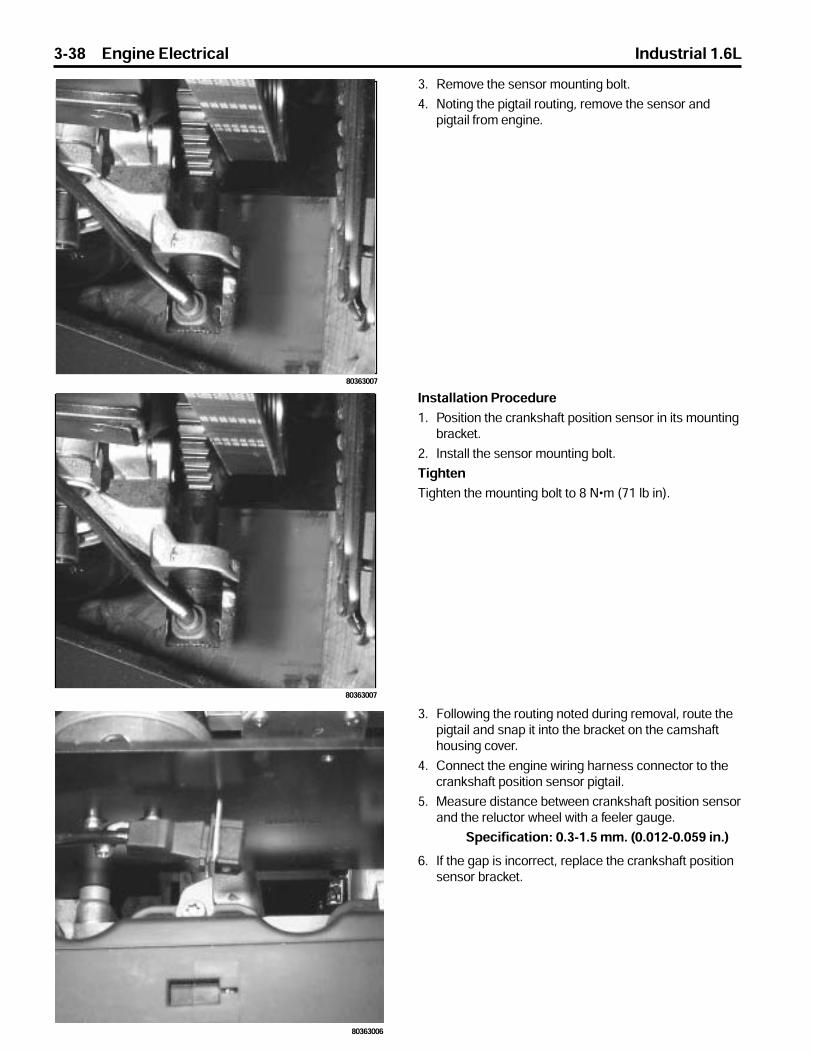
3-38 Engine Electrical Industrial 1.6L
3. Remove the sensor mounting bolt.
4. Noting the pigtail routing, remove the sensor andpigtail from engine.
Installation Procedure
1. Position the crankshaft position sensor in its mountingbracket.
2. Install the sensor mounting bolt.
Tighten
Tighten the mounting bolt to 8 N•m (71 lb in).
3. Following the routing noted during removal, route thepigtail and snap it into the bracket on the camshafthousing cover.
4. Connect the engine wiring harness connector to thecrankshaft position sensor pigtail.
5. Measure distance between crankshaft position sensorand the reluctor wheel with a feeler gauge.
Specification: 0.3-1.5 mm. (0.012-0.059 in.)
6. If the gap is incorrect, replace the crankshaft positionsensor bracket.
80363006
80363007
80363007

Industrial 1.6L Engine Electrical 3-39
Description and Operation
Starting System Description
Cranking CircuitThe cranking circuit consists of the following compo-nents:
• The battery• The starter motor• The ignition switch• All related electrical wiring
For detailed schematics of the starting system refer toSchematic and Routing Diagrams.
Starter MotorThe 1.6 liter 4-cylinder engine uses a Bosch startermotor that is considered repairable.
The starter has an over running roller–type clutch andan enclosed shift lever. The solenoid is sealed in orderto prevent entry of foreign material. The part number isstamped on a label attached to the field frame.
The shift lever mechanism and the solenoid plunger areenclosed in the drive housing in order to protect themfrom exposure to dirt, icing conditions, and splash.The solenoid windings energize when the ignitionswitch is in the START position. The resulting plungerand the shift lever movement causes the pinion tomesh with the engine flywheel ring gear, the solenoidmain contacts close, and the engine cranking takesplace. When the engine starts, the pinion overrunningclutch protects the armature from excessive speed untilthe ignition switch is released, at which time theplunger return spring causes the pinion to disengage.In order to prevent excessive overrunning, release theignition switch immediately when the engine starts.
With battery voltage applied directly to the startermotor, the pull–in coil now has voltage applied to bothends of the coil and current ceases to flow. The startersolenoid remains engaged due to the current flowthrough the hold–in coil alone. The starter motorcontinues to operate until the ignition switch is returnedto the RUN position.
With the ignition switch in the RUN position, voltage isremoved from the starter solenoid S terminal. Voltage isapplied at the solenoid B terminal, so both coils are stillenergized by battery voltage through the closed motorcontacts. However, the forces from these coil windingsnow oppose one another and the plunger returns to thedisengaged position through the operation of the returnspring. This opens the contact within the solenoid toremove battery voltage from the starter motor and themotor stops. Both coils also de–energize. This plungeroperation also retracts the starter drive assembly fromthe flywheel and the engine operates on its own power.
Starting System Circuit Description
Battery voltage is applied at all times to the startersolenoid B (battery) terminal through the positivebattery cable.
When the ignition switch is turned to the STARTposition, battery voltage is applied from the closedcontacts of the ignition switch to S terminal of thestarter solenoid through the BLUE wire.
With voltage applied to the starter solenoid S terminal,current flows through the hold–in coil to the mechanicalground at the solenoid. At the same time, current flowsthrough the pull–in coil and the starter motor to thestarter motor’s mechanical ground. The combinedmagnetic force of the coil windings overcomes the forceof the return spring to pull in and hold in the plunger.The plunger moves the shift lever. This causes the driveassembly to engage with the engine flywheel.
The plunger actuation also operates a contact withinthe starter solenoid which closes to apply batteryvoltage directly to the starter motor. The starter motornow cranks the engine.
80363003

3-40 Engine Electrical Industrial 1.6L
Built–in Hydrometer–If EquippedA built–in temperature compensation hydrometer ismolded into the top of some maintenance free batter-ies. When observing the hydrometer, make sure thebattery top is clean. Use a light in poorly–lit areas.Under normal operating conditions, one of threeindications can be observed:
1. Any green appearance in the hydrometer isinterpreted as a green dot . This means thebattery is ready for testing.
2. A dark dot is visible. If the green dot is not visibleand there is a complaint about cranking, refer toBattery Not Operating Properly or Battery Electri-cal Drain/Parasitic Load.
Batteries
PSI does not supply batteries to equipment manufac-turers. However, on the previous pages, you will findsome generic methods used to diagnosis commonbattery problems. You may need to contact the equip-ment manufacturer for specific procedures and specifi-
cations for the battery you are working with.
3. A clear or light yellow dot means the electrolytelevel is below the bottom of the hydrometer and istoo low for diagnosis. When you find a battery inthis condition, this may indicate high chargingvoltages caused by a faulty charging system.Because of this, the charging and electricalsystems must be checked. Refer to ChargingSystem Check. The yellow dot may have beencaused by the following conditions:
• Excessive or prolonged charging• A broken case• Excessive tipping• If the battery has a yellow or clear hydrometer, replace the battery if a cranking complaint exists.
181056

Industrial 1.6L Engine Electrical 3-41
Charging System DescriptionThe charging system consists of the following compo-nents:
• The battery• The generator• The voltmeter gauge• All related electrical wiring
The generator supplies the electrical power for charg-ing the battery and for operating the accessories.
SI–Series Generators
All PSI 1.6L industrial engines use a Delco-RemyDiode Rectified AC generator. Since these units havean integral voltage regulator, they are referred to as aSystem Integral Charging Unit, or “SI” for short.
The 1.6L engine uses a model 7-SI which provides theproper current output (up to 70 amperes) to meet theneeds of various industrial applications.
A terminal marked “P” on the rear of the generator isavailable to provide a speed input to the tachometer, ifneeded.
The generator has an internal regulator and does nothave a diode trio. The delta stator (1), the rectifierbridge (4), and the rotor with slip rings and brushes (3),are electrically similar to other Delco-Remy generators.The generator uses a conventional fan and pulley. Aninternal fan cools the slip rings, the end frame, therectifier bridge, and the regulator. The voltmeter gaugeindicates the battery’s state of charge in DC volts whenthe ignition switch is in the RUN position and the engineis not running.
When the engine is running, the voltmeter indicates thecondition of the charging system. Indications betweenthe low and high warning zones represent the normaloperating range. Readings in the low warning zone mayoccur when a large number of electrical accessoriesare operating in the vehicle and the engine is left at anidle for an extended period. This condition is normalsince the charging system is not able to provide fullpower at engine idle.
As engine speeds are increased, this condition shouldcorrect itself as higher engine speeds allow the charg-ing system to create maximum power. Continuousreadings in either warning zone indicate problems ifany of the following conditions occur:
• Any abnormal charging condition
• System voltage is too high or too low
80363002
181768

3-42 Engine Electrical Industrial 1.6L
Voltage Regulator
The integral voltage regulator protects the unit’soperating accessories from receiving high voltage andthe battery from being overcharged. No currentregulation is needed because it determined by thedesign of the generator.
The regulator is an extremely reliable device composedof two circuits. One of these circuits is used to sensevoltage and control the other circuit which cycles thefield current “on and off” to prevent voltage from goingto high.
The regulator limits system voltage by controlling therotor field current. When the field current is on, theregulator switches the rotor field on and off at a fixedrate of about 400 cycles per second. By varying theoverall on/off time, correct average field current forproper system voltage control is maintained. At highspeeds, the on time may be 10 percent and the off timemay be 90 percent. At low speeds, and with highelectrical loads, the on/off time may be 90 percent and10 percent respectively.
The regulator has four terminals, The terminals are P,L, I, and S. These letters are stamped on the regulator.
Generally, in SI generators the S terminal senses thestate of the battery and allows field current flow whenthe switch is closed.
When the battery voltage rises to predetermined level,the sensing circuit tells the regulator to turn OFF. Thisdecreases the magnetic field around the field coil andgenerator voltage is limited to a safe value.
When the battery voltage drops below a predeterminedlevel, the sensing circuit tells the regulator to turn ON.This increases the magnetic field around the field coiland generator voltage begins to charge the battery.
Charging System Circuit Description
The generator provides voltage that operates theelectrical system of the vehicle and that also chargesthe battery and the secondary battery. A magnetic fieldis created when current flows through the rotor. Thefield rotates as the rotor is driven by the engine,creating an AC voltage in the stator windings. Therectifier bridge converts the AC voltage to DC and thisgoes to the electrical system at the terminal to thebattery.
The digital regulator of the generator uses digitaltechniques in order to supply the rotor current. Be-cause of this, the digital regulator controls the outputvoltage. The rotor current is proportional the width ofthe electrical pulses supplied from the electrical systemthrough the RED wire connected between the batteryand S terminals on the generator .
When the ignition switch is turned to the RUN position,current from the battery flows through the closedcontacts of the switch, to the voltmeter gauge on theinstrument panel, the voltage regulator, and through thefield coil of the generator rotor.
With current applied to the digital regulator, the regula-tor turns on. Narrow width pulses go to the digital rotorcircuit, creating a weak magnetic field. When theengine starts, the digital regulator senses the rotationof the generator by detecting AC voltage at the statorthrough an internal wire. Once the engine is running,the digital regulator varies the field current by control-ling the pulse width. This regulates the output voltage ofthe generator for proper charging of the battery andoperation of the electrical system.
375662

Industrial 1.6L Engine Electrical 3-43
IGNITION SYSTEM DESCRIPTION
The 1.6 Liter, 4-cylinder engine, is equipped with adistributorless ignition system (DIS). The electroniccontrol unit (ECU) performs all of the ignition controlfunctions based on signals from the crankshaftposition sensor.
The ignition system consists of a battery, the DISignition module containing two coil packs, a crankshaftposition sensor, an ignition switch, the spark plugs, andthe primary and secondary ignition wiring.
Ignition Switch
The ignition switch mounting location is determined bythe customer. The switch has three terminals. The “B”(battery) terminal is connected directly to the batteryand is “hot” at all times. The “I” (ignition) terminal is“hot” when the switch is in the RUN or START posi-tions. This terminal provides current to the ignitionsystem and the engine electrical components such asthe generator field circuit. The “S” terminal is “hot” inSTART only. It provides current to energize the startersolenoid, allowing the starter motor to operate.
DIS Ignition Module
The DIS ignition module contains two ignition coilpacks and is mounted at the rear of the camshafthousing. It is powered by an ignition feed or primarycircuit. Battery voltage is available at the primaryignition terminal “D” of the module anytime the ignitionswitch is in the RUN or START position and terminal“C” provides a dedicated ground.
The secondary circuit is connected to the module andspark plugs by a high tension wires.
The DIS ignition module is controlled by pulses pro-vided by the ECU. The ECU causes a spark to occurby pulsing an IC circuit, which triggers an ignition coiland fires the appropriate spark plug.
One ignition coil pack fires cylinders 1 and 4 while theother coil pack fires cylinders 2 and 3.
80363005

3-44 Engine Electrical Industrial 1.6L
Spark Plugs
The 1.6 Liter engine uses resistor type spark plugs.The plugs used in this engine have a tapered seat,so a gasket is not required.
A spark plug must operate within certain temperaturelimits to provide the performance and service lifeexpected. The plug selected for this engine is basedon the normal service for which the engine wasdesigned. Depending on operating conditions, thespark plug heat range may have to be adjustedupward or downward one range in order to match thespecific engine requirements.
Secondary Wiring
The secondary wires, often referred to as “spark plugwires”, carry voltage between the ignition coil packsand the spark plugs.
The secondary wiring used with the 1.6 Liter engineis a carbon impregnated cord conductor encased inan 8 mm (5/16-inch) diameter silicone rubber jacket.The silicone wiring will withstand very high tempera-tures and also provides an excellent insulator for thehigher voltages of a distributorless ignition system.
The secondary wire connections are covered withrubber boots and form a tight seal to prevent arcing.
Notice: Because the secondary wires are designedfor a tight fit, always remove the wires by pulling onthe boot while exerting a gentle twisting action. Thiswill prevent damage to the wire connectors. Pullingdirectly on the spark plug wires can damage them.
Crankshaft Position (CKP) Sensor
The crankshaft position (CKP) sensor is located atthe lower right front of the engine, near the crank-shaft pulley.
The sensor works in conjunction with a 58 toothreluctor wheel on the crankshaft. The electroniccontrol unit (ECU) monitors the voltage from the CKPsensor circuits.
As the reluctor wheel tooth passes past the sensor,the sensor creates an analog voltage signal. Thisanalog signal is used by the ECU to properly syn-chronize the fuel injectors and the ignition timing.
On some engine applications, this signal can also beused to detect engine misfires.
80363008
Sensor
Reluctor Wheel
80363009
80363004

Industrial 1.6L Engine Electrical 3-45
Special Tools and EquipmentNOTE: The diagnostic tools shown here are available from Kent-Moore. However, equivalenttools supplied by other manufacturers are permissible for use.
8439
95591
3432
3430
Tool Number/DescriptionIllustration
J 21008 -ASelf-Powered Test Light
J 35590Current Clamp
J 38758Parasitic Draw Test Switch
J 39200Digital Multimeter
5382
3431
1025
404758
Tool Number/DescriptionIllustration
J 42000Battery Load Test Tool
J 36169-AFused Jumper Wire
P/N 12303040Battery Terminal Adapters
J 34142-BUnpowered Test Light