Orientational Behavior of Ellipsoidal SilicaCoated ...
9
ISSN 1022–1352 · MCHPES 212 (6) 533–656 (2011) · Vol. 212 · No. 6 · March 15, 2011 D 51046 6/2011 Macromolecular Chemistry and Physics Founded by Hermann Staudinger
Transcript of Orientational Behavior of Ellipsoidal SilicaCoated ...
ISSN 1022–1352 · MCHPES 212 (6) 533–656 (2011) · Vol. 212 · No. 6 · March 15, 2011 D 51046
6/2011
MacromolecularChemistryand Physics Founded by
Hermann Staudinger
Full Paper
Orientational Behavior of Ellipsoidal Silica-Coated Hematite Nanoparticles Integratedwithin an Elastomeric Matrix and itsMechanical Reinforcement
Antoni Sanchez-Ferrer, Raffaele Mezzenga, Herve Dietsch*
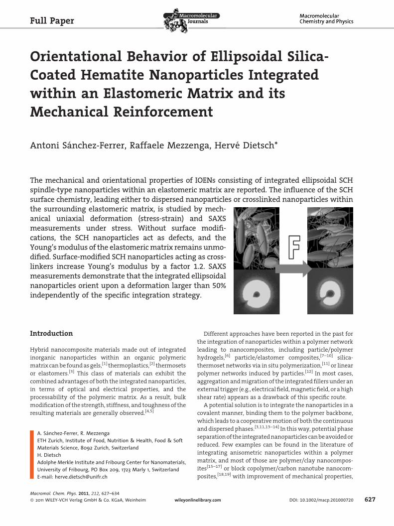
The mechanical and orientational properties of IOENs consisting of integrated ellipsoidal SCHspindle-type nanoparticles within an elastomeric matrix are reported. The influence of the SCHsurface chemistry, leading either to dispersed nanoparticles or crosslinked nanoparticles withinthe surrounding elastomeric matrix, is studied by mech-anical uniaxial deformation (stress-strain) and SAXSmeasurements under stress. Without surface modifi-cations, the SCH nanoparticles act as defects, and theYoung’smodulus of the elastomericmatrix remains unmo-dified. Surface-modified SCH nanoparticles acting as cross-linkers increase Young’s modulus by a factor 1.2. SAXSmeasurements demonstrate that the integrated ellipsoidalnanoparticles orient upon a deformation larger than 50%independently of the specific integration strategy.
Introduction
Hybrid nanocomposite materials made out of integrated
inorganic nanoparticles within an organic polymeric
matrix canbe foundasgels,[1] thermoplastics,[2] thermosets
or elastomers.[3] This class of materials can exhibit the
combined advantages of both the integrated nanoparticles,
in terms of optical and electrical properties, and the
processability of the polymeric matrix. As a result, bulk
modification of the strength, stiffness, and toughness of the
resulting materials are generally observed.[4,5]
A. Sanchez-Ferrer, R. MezzengaETH Zurich, Institute of Food, Nutrition & Health, Food & SoftMaterials Science, 8092 Zurich, SwitzerlandH. DietschAdolphe Merkle Institute and Fribourg Center for Nanomaterials,University of Fribourg, PO Box 209, 1723 Marly 1, SwitzerlandE-mail: [email protected]
Macromol. Chem. Phys. 2011, 212, 627–634
� 2011 WILEY-VCH Verlag GmbH & Co. KGaA, Weinheim wileyonlin
Different approaches have been reported in the past for
the integration of nanoparticles within a polymer network
leading to nanocomposites, including particle/polymer
hydrogels,[6] particle/elastomer composites,[7–10] silica-
thermoset networks via in situ polymerization,[11] or linear
polymer networks induced by particles.[12] In most cases,
aggregationandmigrationof the integratedfillersunder an
external trigger (e.g., electricalfield,magneticfield, orahigh
shear rate) appears as a drawback of this specific route.
A potential solution is to integrate the nanoparticles in a
covalent manner, binding them to the polymer backbone,
which leads to a cooperativemotion of both the continuous
and dispersed phases.[3,11,13–14] In thisway, potential phase
separationof the integratednanoparticles canbeavoidedor
reduced. Few examples can be found in the literature of
integrating anisometric nanoparticles within a polymer
matrix, and most of those are polymer/clay nanocompos-
ites[15–17] or block copolymer/carbon nanotube nanocom-
posites,[18,19] with improvement of mechanical properties,
elibrary.com DOI: 10.1002/macp.201000720 627
628
www.mcp-journal.de
A. Sanchez-Ferrer, R. Mezzenga, H. Dietsch
but still with aggregation of the nanoparticles in clusters.
Tworecentsuccessfulworksonthe integrationofwires into
a liquid-crystalline polymer network,[20] and ellipsoidal
nanoparticles into block copolymers[21] were also reported.
So far, no examples are available where anisometric
nanoparticles are present in a chemical elastomeric
network as crosslinkers, and the mechanical and orienta-
tional behavior of both nanoparticles and polymer matrix
are studied in detail. In this context, a strategy towards
inorganic/organic elastomer nanocomposites (IOENs) was
also recently proposed using silica-coated hematite (SCH)
which was integrated within an elastomeric matrix.[22]
Evidence concerning the quality of the dispersion and
distribution of the nanofillers within the matrix was
obtained for surface-treated SCH with one of both
functionalities taking part in the polyaddition process.[3]
However, the impact on the structural and mechanical
properties provided by the presence of integrated nano-
particles within the elastomeric matrix was not disclosed,
which is the main motivation for the present work.
In the current study we investigate whether integrated
ellipsoidal nanoparticles can bothmechanically reinforce an
elastomeric matrix and orient under stress (i.e., coupling
between the polymer network and the nanoparticles). To
this end, nanoparticles acting as crosslinkers or mixed in an
uncontrolledwayhavebeencomparedatanequivalentfiller
concentration and evaluated by both classical mechanical
tests and scattering patterns under mechanical stress.
Experimental Part
Materials
Iron(III) perchlorate hexahydrate [Fe(ClO4)3 �6H2O], poly(vinylpyr-
rolidone) (PVP, 10000g �mol�1), and a 25% solution of tetramethyl-
ammonium hydroxide (TMAH) in methanol were all provided by
Sigma-Aldrich and used as received. Sodium dihydrogen phosphate
monohydrate (NaH2PO4 �H2O), urea, and absolute ethanol were
provided by Fluka. Tetraethylorthosilicate (TEOS) and acetone were
provided byMerck, and 3-aminopropyltriethoxysilane (APTES) from
ABCR, were also used without further purification. Ultrapure water
(18.2MV � cm) purifiedby aMilliQ system,wasused throughout the
experiments. The diamine-terminated poly(propylene oxide) poly-
mer Jeffamine D-2000 with approximate number-average mole-
cularmass (Mn) of2 000g �mol�1waskindlyprovidedbyHuntsman
Corporation and degassed before use. The triisocyanate crosslinker
BasonatHI-100waskindlyprovidedbyBASFSE
and used as received.
Fe(ClO4)3NaH2PO4
Urea H2O98 ºC, 24 h
PVP
H2O25 ºC, 12 h
TEOS
H2O/EtOHMe4N+Cl-
25 ºC, 1 h
APTES
25 ºC, 24 h
NP FNPHematite PVP-Hematite
Fe(ClO4)3NaH2PO4
Urea H2O98 ºC, 24 h
PVP
H2O25 ºC, 12 h
TEOS
H2O/EtOHMe4N+Cl-
25 ºC, 1 h
APTES
25 ºC, 24 h
NP FNPHematite PVP-Hematite
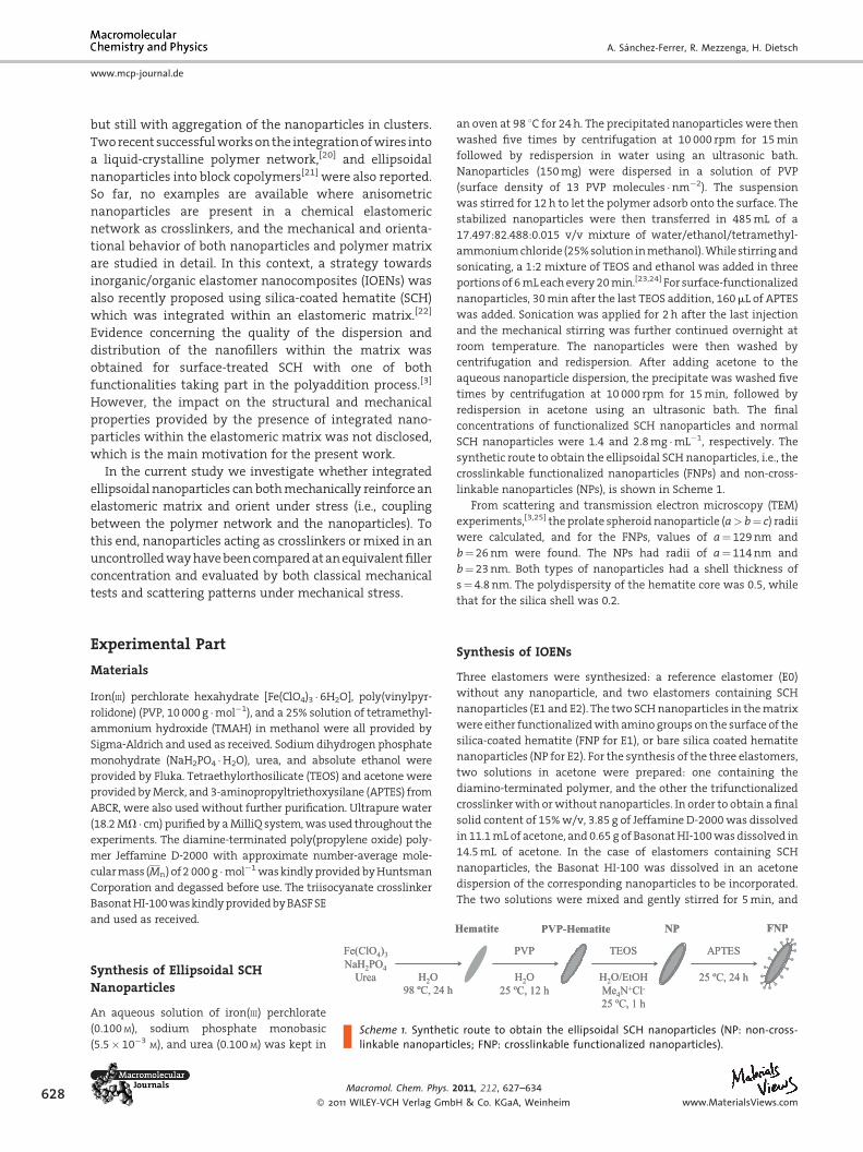
Scheme 1. Synthetic route to obtain the ellipsoidal SCH nanoparticles (NP: non-cross-linkable nanoparticles; FNP: crosslinkable functionalized nanoparticles).
Synthesis of Ellipsoidal SCH
Nanoparticles
An aqueous solution of iron(III) perchlorate
(0.100M), sodium phosphate monobasic
(5.5� 10�3M), and urea (0.100M) was kept in
Macromol. Chem. Phys. 2
� 2011 WILEY-VCH Verlag Gmb
an oven at 98 8C for 24h. The precipitated nanoparticles were then
washed five times by centrifugation at 10 000 rpm for 15min
followed by redispersion in water using an ultrasonic bath.
Nanoparticles (150mg) were dispersed in a solution of PVP
(surface density of 13 PVP molecules �nm�2). The suspension
was stirred for 12h to let the polymer adsorb onto the surface. The
stabilized nanoparticles were then transferred in 485mL of a
17.497:82.488:0.015 v/v mixture of water/ethanol/tetramethyl-
ammoniumchloride (25%solution inmethanol).While stirringand
sonicating, a 1:2 mixture of TEOS and ethanol was added in three
portionsof 6mLeachevery20min.[23,24] For surface-functionalized
nanoparticles, 30min after the last TEOS addition, 160mL of APTES
was added. Sonication was applied for 2h after the last injection
and the mechanical stirring was further continued overnight at
room temperature. The nanoparticles were then washed by
centrifugation and redispersion. After adding acetone to the
aqueous nanoparticle dispersion, the precipitate was washed five
times by centrifugation at 10 000 rpm for 15min, followed by
redispersion in acetone using an ultrasonic bath. The final
concentrations of functionalized SCH nanoparticles and normal
SCH nanoparticles were 1.4 and 2.8mg �mL�1, respectively. The
synthetic route to obtain the ellipsoidal SCH nanoparticles, i.e., the
crosslinkable functionalized nanoparticles (FNPs) and non-cross-
linkable nanoparticles (NPs), is shown in Scheme 1.
From scattering and transmission electron microscopy (TEM)
experiments,[3,25] the prolate spheroid nanoparticle (a> b¼ c) radii
were calculated, and for the FNPs, values of a¼ 129nm and
b¼26nm were found. The NPs had radii of a¼114nm and
b¼23nm. Both types of nanoparticles had a shell thickness of
s¼4.8 nm. The polydispersity of the hematite core was 0.5, while
that for the silica shell was 0.2.
Synthesis of IOENs
Three elastomers were synthesized: a reference elastomer (E0)
without any nanoparticle, and two elastomers containing SCH
nanoparticles (E1 and E2). The two SCHnanoparticles in thematrix
were either functionalizedwith amino groups on the surface of the
silica-coated hematite (FNP for E1), or bare silica coated hematite
nanoparticles (NP for E2). For the synthesis of the three elastomers,
two solutions in acetone were prepared: one containing the
diamino-terminated polymer, and the other the trifunctionalized
crosslinkerwith orwithout nanoparticles. In order to obtain a final
solid content of 15%w/v, 3.85 g of Jeffamine D-2000was dissolved
in 11.1mLof acetone, and0.65 g of BasonatHI-100wasdissolved in
14.5mL of acetone. In the case of elastomers containing SCH
nanoparticles, the Basonat HI-100 was dissolved in an acetone
dispersion of the corresponding nanoparticles to be incorporated.
The two solutions were mixed and gently stirred for 5min, and
011, 212, 627–634
H & Co. KGaA, Weinheim www.MaterialsViews.com
H2NO
NH2
33 N N
N
NCO
NCO
OCN
O O
O
6
66
Nanoparticles
acetone25 ºC, 1 day
+
Polymer(Jeffamine® D-2000)
Crosslinker(Basonat® HI-100)
IOEN
H2NO
NH2
33 N N
N
NCO
NCO
OCN
O O
O
6
66
Nanoparticles
acetone25 ºC, 1 day
+
Polymer(Jeffamine® D-2000)
Crosslinker(Basonat® HI-100)
IOEN
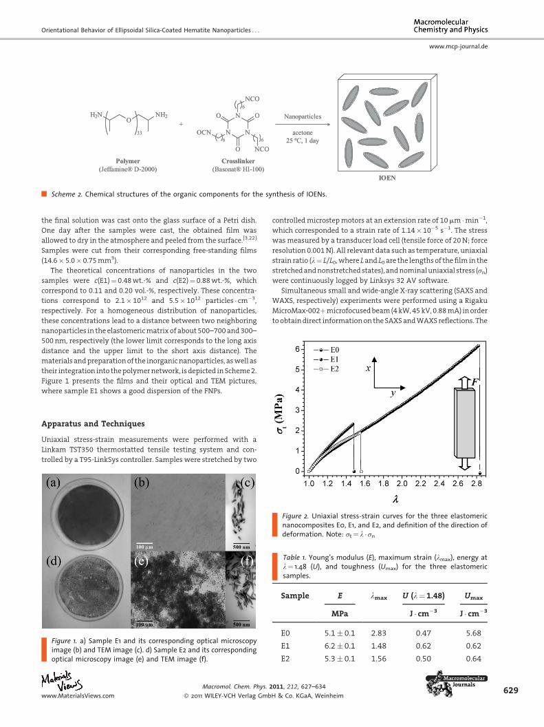
Scheme 2. Chemical structures of the organic components for the synthesis of IOENs.
Orientational Behavior of Ellipsoidal Silica-Coated Hematite Nanoparticles . . .
www.mcp-journal.de
the final solution was cast onto the glass surface of a Petri dish.
One day after the samples were cast, the obtained film was
allowed to dry in the atmosphere and peeled from the surface.[3,22]
Samples were cut from their corresponding free-standing films
(14.6�5.0�0.75mm3).
The theoretical concentrations of nanoparticles in the two
samples were c(E1)¼ 0.48wt.-% and c(E2)¼ 0.88wt.-%, which
correspond to 0.11 and 0.20 vol.-%, respectively. These concentra-
tions correspond to 2.1�1012 and 5.5� 1012 particles � cm�3,
respectively. For a homogeneous distribution of nanoparticles,
these concentrations lead to a distance between two neighboring
nanoparticles in the elastomericmatrix of about500–700and300–
500nm, respectively (the lower limit corresponds to the long axis
distance and the upper limit to the short axis distance). The
materialsandpreparationof the inorganicnanoparticles, aswell as
their integration into thepolymernetwork, isdepicted inScheme2.
Figure 1 presents the films and their optical and TEM pictures,
where sample E1 shows a good dispersion of the FNPs.
Apparatus and Techniques
Uniaxial stress-strain measurements were performed with a
Linkam TST350 thermostatted tensile testing system and con-
trolled by a T95-LinkSys controller. Samples were stretched by two
Figure 1. a) Sample E1 and its corresponding optical microscopyimage (b) and TEM image (c). d) Sample E2 and its correspondingoptical microscopy image (e) and TEM image (f).
www.MaterialsViews.com
Macromol. Chem. Phys. 2
� 2011 WILEY-VCH Verlag Gmb
controlledmicrostepmotors at an extension rate of 10mm �min�1,
which corresponded to a strain rate of 1.14�10�5 s�1. The stress
wasmeasured by a transducer load cell (tensile force of 20N; force
resolution 0.001N). All relevant data such as temperature, uniaxial
strain ratio (l¼ L/L0,where Land L0 are the lengthsof thefilm in the
stretchedandnonstretchedstates), andnominaluniaxial stress (sn)
were continuously logged by Linksys 32 AV software.
Simultaneous small and wide-angle X-ray scattering (SAXS and
WAXS, respectively) experiments were performed using a Rigaku
MicroMax-002þmicrofocusedbeam(4 kW,45 kV,0.88mA) inorder
toobtaindirect informationon theSAXSandWAXS reflections. The
Figure 2. Uniaxial stress-strain curves for the three elastomericnanocomposites E0, E1, and E2, and definition of the direction ofdeformation. Note: st ¼ l � sn
Table 1. Young’s modulus (E), maximum strain (lmax), energy atl¼ 1.48 (U), and toughness (Umax) for the three elastomericsamples.
Sample E lmax U (l¼ 1.48) Umax
MPa J � cm�3 J � cm�3
E0 5.1� 0.1 2.83 0.47 5.68
E1 6.2� 0.1 1.48 0.62 0.62
E2 5.3� 0.1 1.56 0.50 0.64
011, 212, 627–634
H & Co. KGaA, Weinheim629
1 10q (nm-1)
E2
Intensity
(a.u
.) E1
E0
11.0q (nm-1)
E2
Intensity
(a.u
.) E1
E0
qPC
qMPS )b )a
qFNPa
qFNPb
qNPa
qNPb
qMPS
qMPS
qMPS
qMPS
qMPS
qPC
qPC
qH
qH
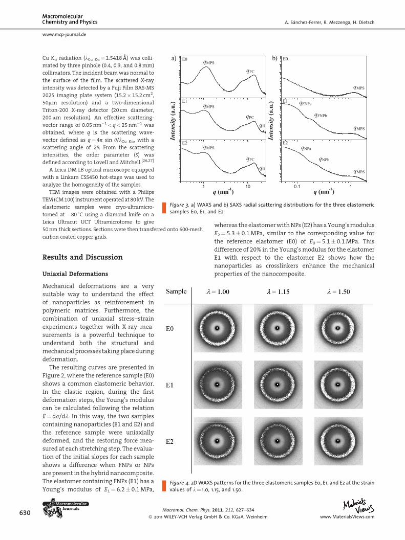
Figure 3. a) WAXS and b) SAXS radial scattering distributions for the three elastomericsamples E0, E1, and E2.
630
www.mcp-journal.de
A. Sanchez-Ferrer, R. Mezzenga, H. Dietsch
Cu Ka radiation (lCu Ka¼1.5418 A) was colli-
mated by three pinhole (0.4, 0.3, and 0.8mm)
collimators. The incident beamwas normal to
the surface of the film. The scattered X-ray
intensity was detected by a Fuji Film BAS-MS
2025 imaging plate system (15.2�15.2 cm2,
50mm resolution) and a two-dimensional
Triton-200 X-ray detector (20 cm diameter,
200mm resolution). An effective scattering-
vector range of 0.05nm�1< q<25nm�1 was
obtained, where q is the scattering wave-
vector defined as q¼4p sin u/lCu Ka, with a
scattering angle of 2u. From the scattering
intensities, the order parameter (S) was
defined according to Lovell and Mitchell.[26,27]
A Leica DM LB optical microscope equipped
with a Linkam CSS450 hot-stage was used to
analyze the homogeneity of the samples.
TEM images were obtained with a Philips
TEM(CM100) instrumentoperatedat80kV.The
elastomeric samples were cryo-ultramicro-
tomed at �80 8C using a diamond knife on a
Leica Ultracut UCT Ultramicrotome to give
50nm thick sections. Sections were then transferred onto 600-mesh
carbon-coated copper grids.
Results and Discussion
Uniaxial Deformations
Figure 4. 2D WAXS patterns for the three elastomeric samples E0, E1, and E2 at the strainvalues of l¼ 1.0, 1.15, and 1.50.
Mechanical deformations are a very
suitable way to understand the effect
of nanoparticles as reinforcement in
polymeric matrices. Furthermore, the
combination of uniaxial stress–strain
experiments together with X-ray mea-
surements is a powerful technique to
understand both the structural and
mechanicalprocesses takingplaceduring
deformation.
The resulting curves are presented in
Figure 2, where the reference sample (E0)
shows a common elastomeric behavior.
In the elastic region, during the first
deformation steps, the Young’s modulus
can be calculated following the relation
E¼ds/dl. In this way, the two samples
containing nanoparticles (E1 and E2) and
the reference sample were uniaxially
deformed, and the restoring force mea-
sured at each stretching step. The evalua-
tion of the initial slopes for each sample
shows a difference when FNPs or NPs
are present in the hybrid nanocomposite.
The elastomer containing FNPs (E1) has a
Young’s modulus of E1¼ 6.2� 0.1MPa,
Macromol. Chem. Phys. 2
� 2011 WILEY-VCH Verlag Gmb
whereas theelastomerwithNPs (E2)hasaYoung’smodulus
E2¼ 5.3� 0.1MPa, similar to the corresponding value for
the reference elastomer (E0) of E0¼ 5.1� 0.1MPa. This
difference of 20% in the Young’smodulus for the elastomer
E1 with respect to the elastomer E2 shows how the
nanoparticles as crosslinkers enhance the mechanical
properties of the nanocomposite.
011, 212, 627–634
H & Co. KGaA, Weinheim www.MaterialsViews.com
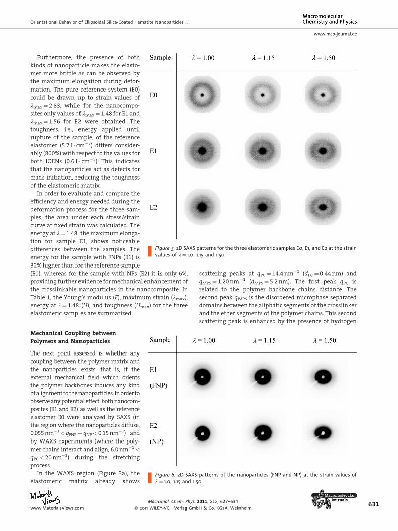
Figure 5. 2D SAXS patterns for the three elastomeric samples E0, E1, and E2 at the strainvalues of l¼ 1.0, 1.15 and 1.50.
Orientational Behavior of Ellipsoidal Silica-Coated Hematite Nanoparticles . . .
www.mcp-journal.de
Furthermore, the presence of both
kinds of nanoparticle makes the elasto-
mer more brittle as can be observed by
the maximum elongation during defor-
mation. The pure reference system (E0)
could be drawn up to strain values of
lmax¼ 2.83, while for the nanocompo-
sites only values of lmax¼ 1.48 for E1 and
lmax¼ 1.56 for E2 were obtained. The
toughness, i.e., energy applied until
rupture of the sample, of the reference
elastomer (5.7 J � cm�3) differs consider-
ably (800%)with respect to the values for
both IOENs (0.6 J � cm�3). This indicates
that the nanoparticles act as defects for
crack initiation, reducing the toughness
of the elastomeric matrix.
In order to evaluate and compare the
efficiency and energy needed during the
deformation process for the three sam-
ples, the area under each stress/strain
curve at fixed strain was calculated. The
energy at l¼ 1.48, themaximumelonga-
tion for sample E1, shows noticeable
differences between the samples. The
energy for the sample with FNPs (E1) is
32% higher than for the reference sample
(E0), whereas for the sample with NPs (E2) it is only 6%,
providing further evidence formechanical enhancement of
the crosslinkable nanoparticles in the nanocomposite. In
Table 1, the Young’s modulus (E), maximum strain (lmax),
energy at l¼ 1.48 (U), and toughness (Umax) for the three
elastomeric samples are summarized.
Figure 6. 2D SAXS patterns of the nanoparticles (FNP and NP) at the strain values ofl¼ 1.0, 1.15 and 1.50.
Mechanical Coupling betweenPolymers and Nanoparticles
The next point assessed is whether any
coupling between the polymer matrix and
the nanoparticles exists, that is, if the
external mechanical field which orients
the polymer backbones induces any kind
ofalignmenttothenanoparticles. Inorderto
observeanypotential effect, bothnanocom-
posites (E1 and E2) as well as the reference
elastomer E0 were analyzed by SAXS (in
the region where the nanoparticles diffuse,
0.055nm�1< qFNP� qNP< 0.15nm�1) and
by WAXS experiments (where the poly-
mer chains interact and align, 6.0nm�1<
qPC< 20nm�1) during the stretching
process.
In the WAXS region (Figure 3a), the
elastomeric matrix already shows
www.MaterialsViews.com
Macromol. Chem. Phys. 2
� 2011 WILEY-VCH Verlag Gmb
scattering peaks at qPC¼ 14.4 nm�1 (dPC¼ 0.44nm) and
qMPS¼ 1.20nm�1 (dMPS¼ 5.2 nm). The first peak qPC is
related to the polymer backbone chains distance. The
second peak qMPS is the disordered microphase separated
domains between the aliphatic segments of the crosslinker
and the ether segments of the polymer chains. This second
scattering peak is enhanced by the presence of hydrogen
011, 212, 627–634
H & Co. KGaA, Weinheim631
0 90 180 270 360
ϕ (deg)
λ = 1.50
Intensity
(a.u
.) λ = 1.15
λ = 1.00 6.0 < qPC < 20
0 90 180 270 360
ϕ (deg)
λ = 1.50
Intensity
(a.u
.) λ = 1.15
0.60 < qMPS < 2.0λ = 1.00
0 90 180 270 360
ϕ (deg)
λ = 1.50
Intensity
(a.u
.) λ = 1.15
0.14 < qFNPb < 0.30λ = 1.00
0 90 180 270 360
ϕ (deg)
λ = 1.50
Intensity
(a.u
.) λ = 1.15
0.055 < qFNPa < 0.14λ = 1.00
)b )a
)d )c
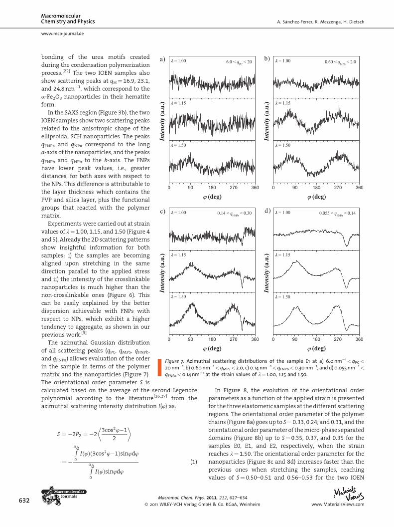
Figure 7. Azimuthal scattering distributions of the sample E1 at a) 6.0 nm�1<qPC <
20 nm�1, b) 0.60 nm�1<qMPS< 2.0, c) 0.14 nm�1<qFNPb<0.30 nm�1, and d) 0.055 nm�1<
qFNPa<0.14 nm�1 at the strain values of l¼ 1.00, 1.15 and 1.50.
632
www.mcp-journal.de
A. Sanchez-Ferrer, R. Mezzenga, H. Dietsch
bonding of the urea motifs created
during the condensation polymerization
process.[22] The two IOEN samples also
show scattering peaks at qH¼ 16.9, 23.1,
and 24.8 nm�1, which correspond to the
a-Fe2O3 nanoparticles in their hematite
form.
In the SAXS region (Figure 3b), the two
IOEN samples show two scattering peaks
related to the anisotropic shape of the
ellipsoidal SCH nanoparticles. The peaks
qFNPa and qNPa correspond to the long
a-axis of the nanoparticles, and the peaks
qFNPb and qNPb to the b-axis. The FNPs
have lower peak values, i.e., greater
distances, for both axes with respect to
the NPs. This difference is attributable to
the layer thickness which contains the
PVP and silica layer, plus the functional
groups that reacted with the polymer
matrix.
Experiments were carried out at strain
values of l¼ 1.00, 1.15, and 1.50 (Figure 4
and5). Already the2Dscatteringpatterns
show insightful information for both
samples: i) the samples are becoming
aligned upon stretching in the same
direction parallel to the applied stress
and ii) the intensity of the crosslinkable
nanoparticles is much higher than the
non-crosslinkable ones (Figure 6). This
can be easily explained by the better
dispersion achievable with FNPs with
respect to NPs, which exhibit a higher
tendency to aggregate, as shown in our
previous work.[3]
The azimuthal Gaussian distribution
of all scattering peaks (qPC, qMPS, qFNPb,
and qFNPa) allows evaluation of the order
in the sample in terms of the polymer
matrix and the nanoparticles (Figure 7).
The orientational order parameter S is
calculated based on the average of the second Legendre
polynomial according to the literature[26,27] from the
azimuthal scattering intensity distribution I(w) as:
S ¼ �2P2 ¼ �23cos2’�1
2
� �
¼ �
Rp=20
Ið’Þ 3cos2’�1ð Þsin’d’
Rp=20
Ið’Þsin’d’(1)
Macromol. Chem. Phys. 2
� 2011 WILEY-VCH Verlag Gmb
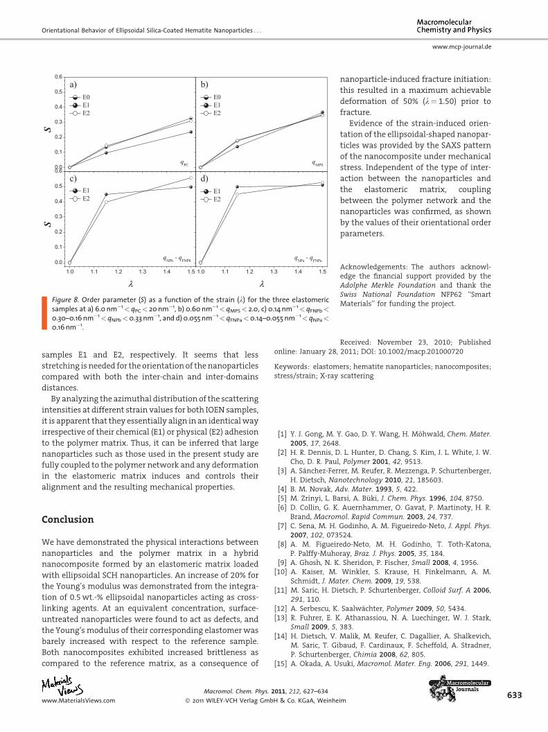
In Figure 8, the evolution of the orientational order
parameters as a function of the applied strain is presented
for the three elastomeric samples at the different scattering
regions. The orientational order parameter of the polymer
chains (Figure 8a) goes up to S¼ 0.33, 0.24, and 0.31, and the
orientational orderparameterof themicro-phase separated
domains (Figure 8b) up to S¼ 0.35, 0.37, and 0.35 for the
samples E0, E1, and E2, respectively, when the strain
reaches l¼ 1.50. The orientational order parameter for the
nanoparticles (Figure 8c and 8d) increases faster than the
previous ones when stretching the samples, reaching
values of S¼ 0.50–0.51 and 0.56–0.53 for the two IOEN
011, 212, 627–634
H & Co. KGaA, Weinheim www.MaterialsViews.com
0.0
0.1
0.2
0.3
0.4
0.5
0.6
E0 E1 E2
S
qPC
a) b)
qMPS
E0 E1 E2
1.0 1.1 1.2 1.3 1.4 1.5
0.0
0.1
0.2
0.3
0.4
0.5
0.6c)
qNPb - qFNPb
E1 E2
S
λ1.0 1.1 1.2 1.3 1.4 1.5
d)
qNPa - qFNPa
E1 E2
λ
Figure 8. Order parameter (S) as a function of the strain (l) for the three elastomericsamples at a) 6.0 nm�1<qPC< 20 nm�1, b) 0.60 nm�1<qMPS< 2.0, c) 0.14 nm�1< qFNPb<
0.30–0.16 nm�1<qNPb<0.33 nm�1, and d) 0.055 nm�1< qFNPa<0.14–0.055 nm�1<qNPa<
0.16 nm�1.
Orientational Behavior of Ellipsoidal Silica-Coated Hematite Nanoparticles . . .
www.mcp-journal.de
samples E1 and E2, respectively. It seems that less
stretching is needed for the orientation of thenanoparticles
compared with both the inter-chain and inter-domains
distances.
By analyzing the azimuthal distribution of the scattering
intensities at different strain values for both IOEN samples,
it is apparent that they essentially align in an identicalway
irrespective of their chemical (E1) or physical (E2) adhesion
to the polymer matrix. Thus, it can be inferred that large
nanoparticles such as those used in the present study are
fully coupled to the polymer network and any deformation
in the elastomeric matrix induces and controls their
alignment and the resulting mechanical properties.
Conclusion
We have demonstrated the physical interactions between
nanoparticles and the polymer matrix in a hybrid
nanocomposite formed by an elastomeric matrix loaded
with ellipsoidal SCH nanoparticles. An increase of 20% for
the Young’s modulus was demonstrated from the integra-
tion of 0.5wt.-% ellipsoidal nanoparticles acting as cross-
linking agents. At an equivalent concentration, surface-
untreated nanoparticles were found to act as defects, and
the Young’smodulus of their corresponding elastomerwas
barely increased with respect to the reference sample.
Both nanocomposites exhibited increased brittleness as
compared to the reference matrix, as a consequence of
www.MaterialsViews.com
Macromol. Chem. Phys. 2011, 212, 627–634
� 2011 WILEY-VCH Verlag GmbH & Co. KGaA, Weinhe
nanoparticle-induced fracture initiation:
this resulted in a maximum achievable
deformation of 50% (l¼ 1.50) prior to
fracture.
Evidence of the strain-induced orien-
tation of the ellipsoidal-shaped nanopar-
ticles was provided by the SAXS pattern
of the nanocomposite under mechanical
stress. Independent of the type of inter-
action between the nanoparticles and
the elastomeric matrix, coupling
between the polymer network and the
nanoparticles was confirmed, as shown
by the values of their orientational order
parameters.
Acknowledgements: The authors acknowl-edge the financial support provided by theAdolphe Merkle Foundation and thank theSwiss National Foundation NFP62 ‘‘SmartMaterials’’ for funding the project.
Received: November 23, 2010; Published
online: January 28, 2011; DOI: 10.1002/macp.201000720Keywords: elastomers; hematite nanoparticles; nanocomposites;stress/strain; X-ray scattering
[1] Y. J. Gong, M. Y. Gao, D. Y. Wang, H. Mohwald, Chem. Mater.2005, 17, 2648.
[2] H. R. Dennis, D. L. Hunter, D. Chang, S. Kim, J. L. White, J. W.Cho, D. R. Paul, Polymer 2001, 42, 9513.
[3] A. Sanchez-Ferrer, M. Reufer, R. Mezzenga, P. Schurtenberger,H. Dietsch, Nanotechnology 2010, 21, 185603.
[4] B. M. Novak, Adv. Mater. 1993, 5, 422.[5] M. Zrınyi, L. Barsi, A. Buki, J. Chem. Phys. 1996, 104, 8750.[6] D. Collin, G. K. Auernhammer, O. Gavat, P. Martinoty, H. R.
Brand, Macromol. Rapid Commun. 2003, 24, 737.[7] C. Sena, M. H. Godinho, A. M. Figueiredo-Neto, J. Appl. Phys.
2007, 102, 073524.[8] A. M. Figueiredo-Neto, M. H. Godinho, T. Toth-Katona,
P. Palffy-Muhoray, Braz. J. Phys. 2005, 35, 184.[9] A. Ghosh, N. K. Sheridon, P. Fischer, Small 2008, 4, 1956.[10] A. Kaiser, M. Winkler, S. Krause, H. Finkelmann, A. M.
Schmidt, J. Mater. Chem. 2009, 19, 538.[11] M. Saric, H. Dietsch, P. Schurtenberger, Colloid Surf. A 2006,
291, 110.[12] A. Serbescu, K. Saalwachter, Polymer 2009, 50, 5434.[13] R. Fuhrer, E. K. Athanassiou, N. A. Luechinger, W. J. Stark,
Small 2009, 5, 383.[14] H. Dietsch, V. Malik, M. Reufer, C. Dagallier, A. Shalkevich,
M. Saric, T. Gibaud, F. Cardinaux, F. Scheffold, A. Stradner,P. Schurtenberger, Chimia 2008, 62, 805.
[15] A. Okada, A. Usuki, Macromol. Mater. Eng. 2006, 291, 1449.
im633
634
www.mcp-journal.de
A. Sanchez-Ferrer, R. Mezzenga, H. Dietsch
[16] S. Pradhan, F. R. Costa, U. Wagenknecht, D. Jehnichen, A. K.Bhowmick, G. Heinrich, Eur. Polym. J. 2008, 44, 3122.
[17] H. S. Lee, P. D. Fasulo, W. R. Rodgers, D. R. Paul, Polymer 2005,46, 11673.
[18] A. Kelarakis, K. Yoon, I. Sics, R. H. Somani, B. S. Hsiao, B. Chu,Polymer 2005, 46, 5103.
[19] Y. Li, H. Shimizu, Macromolecules 2009, 42, 2587.[20] Y. Y. Huang, J. Biggins, Y. Ji, E. M. Tenrentjev, J. Appl. Phys.
2010, 107, 083515.[21] M. R. Hammond, H. Dietsch, O. Pravaz, P. Schurtenberger,
Macromolecules 2010, 43, 8340.
Macromol. Chem. Phys. 2
� 2011 WILEY-VCH Verlag Gmb
[22] A. Sanchez-Ferrer, D. Rogez, P. Martinoty, Macromol. Chem.Phys. 2010, 211, 1712.
[23] M. Ocana, M. P. Morales, C. J. Serna, J. Colloid Interface Sci.1999, 212, 317.
[24] S. Sacanna, L. Rossi, B.Kuipers,A. Philipse, Langmuir2006,22,1822.[25] M. Reufer, H. Dietsch, U. Gasser, A. M. Hirt, A. Menzel,
P. Schurtenberger, J. Phys. Chem. B 2010, 114, 4763.[26] R. Lovell, G. R. Mitchell, Acta Crystallogr. A 1981, 37, 135.[27] G. R. Mitchell, A. H. Windle, ‘‘Development in Crystalline
Polymers-2’’,D. C. Basset, Ed., Elsevier Applied Science, London1988, Vol. 3, p. 115.
011, 212, 627–634
H & Co. KGaA, Weinheim www.MaterialsViews.com