Optimization of a 3-Cylinder CNG Engine within a Hybrid Powertrain€¦ · · 2015-08-20Engine...
19
Optimization of a 3-Cylinder CNG Engine within a Hybrid Powertrain Universität Stuttgart In Kooperation mit: Di l I D ilBl d 11/5/2008; Dateiname Folie 1 Dipl.-Ing. Daniel Boland October 20th, 2008
Transcript of Optimization of a 3-Cylinder CNG Engine within a Hybrid Powertrain€¦ · · 2015-08-20Engine...
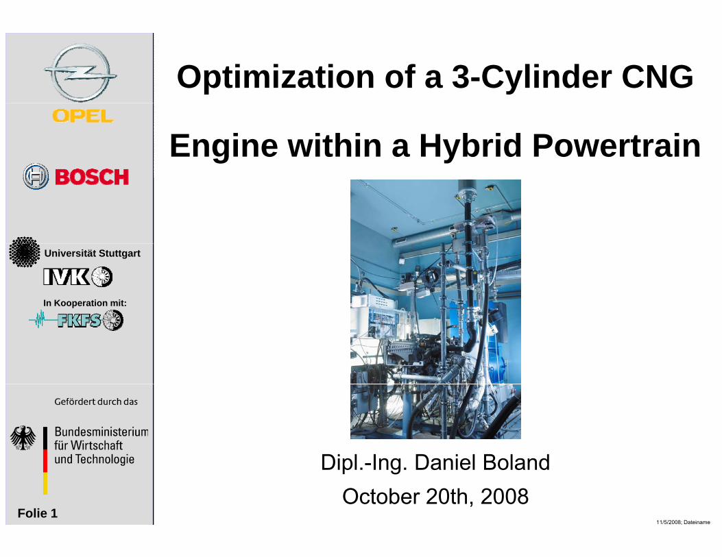
Optimization of a 3-Cylinder CNG
Engine within a Hybrid Powertrain
Universität Stuttgart
In Kooperation mit:
Di l I D i l B l d
11/5/2008; DateinameFolie 1
Dipl.-Ing. Daniel Boland October 20th, 2008
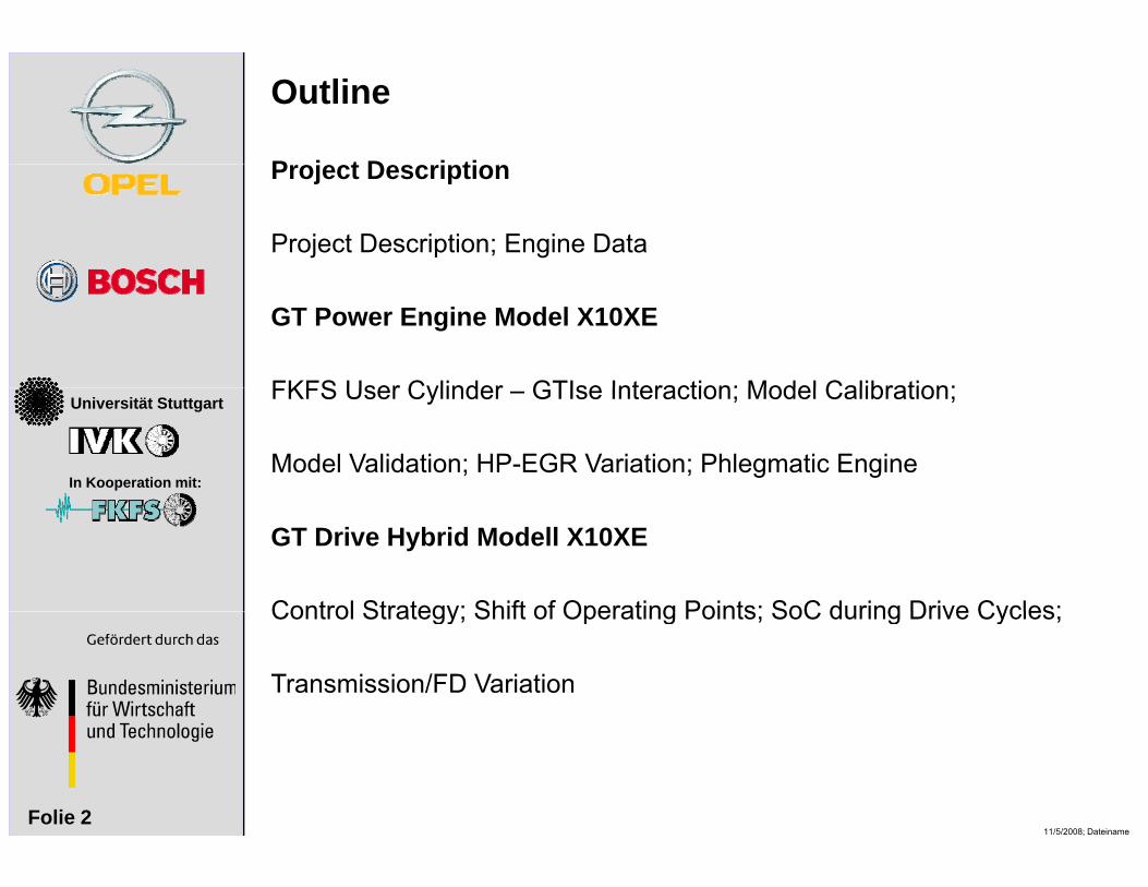
Outline
P j t D i tiProject Description
Project Description; Engine Data
GT Power Engine Model X10XE
FKFS User Cylinder GTIse Interaction; Model Calibration;Universität Stuttgart
In Kooperation mit:
FKFS User Cylinder – GTIse Interaction; Model Calibration;
Model Validation; HP-EGR Variation; Phlegmatic Engine
GT Drive Hybrid Modell X10XE
Control Strategy; Shift of Operating Points; SoC during Drive Cycles;Control Strategy; Shift of Operating Points; SoC during Drive Cycles;
Transmission/FD Variation
11/5/2008; DateinameFolie 2
Universität Stuttgart
In Kooperation mit:
Project Description
11/5/2008; DateinameFolie 3
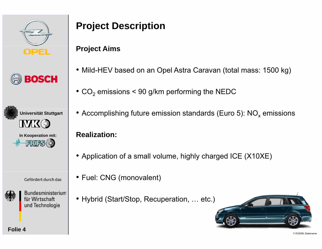
Project Description
P j t AiProject Aims
• Mild-HEV based on an Opel Astra Caravan (total mass: 1500 kg)
• CO2 emissions < 90 g/km performing the NEDC
Universität Stuttgart
In Kooperation mit: Realization:
• Accomplishing future emission standards (Euro 5): NOx emissions
• Application of a small volume, highly charged ICE (X10XE)
• Hybrid (Start/Stop, Recuperation, … etc.)
• Fuel: CNG (monovalent)
11/5/2008; DateinameFolie 4
y ( )

Engine Data
E i D t U itEngine Data: Unit:Type Family 0 (1. Gen.)Number of Cylinders 3Displacement 973 cm3
Compression Ratio ε* 1:10.6 (TD)Connecting Rod length* 132.5 mm
Universität Stuttgart
In Kooperation mit:
g gStroke* 78.6 mmBore 72.5 mmNumber of Valves 4 (IV: 2; EV: 2)Number of Valves 4 (IV: 2; EV: 2)Rated Power* 71 kW (5500 rpm)Rated Torque* 160 Nm
(2000 4000 )(2000 - 4000 rpm)Rated Engine Speed* 5500 rpmInjection Valve NGI 2 (Bosch)
11/5/2008; DateinameFolie 5
ECU* ME 1.5.5
* modified in comparison to series engine
Universität Stuttgart
In Kooperation mit:
GT Power Engine Model X10XE
11/5/2008; DateinameFolie 6
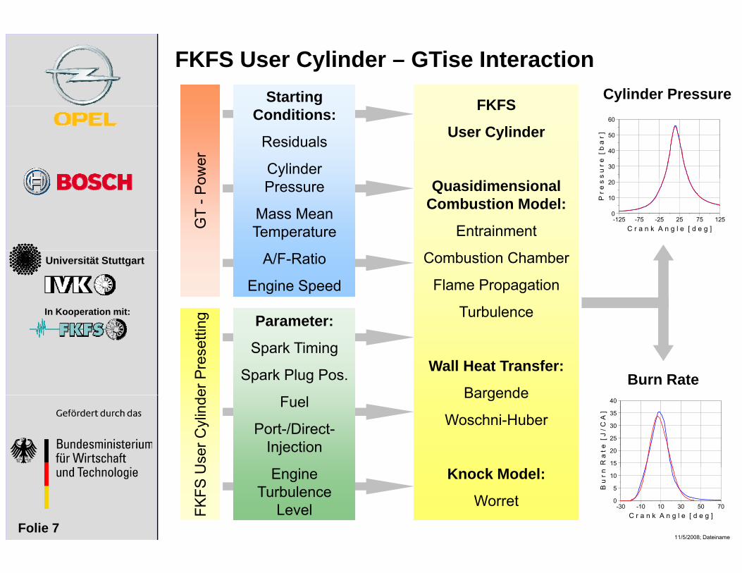
FKFS User Cylinder – GTise InteractionStarting FKFS
Cylinder Pressure
s u
r e [
b a
r ]
30
40
50
60Conditions:
Residuals
Cylinder
FKFS
User Cylinder
ower
P r e
s
0
10
20
C r a n k A n g l e [ d e g ]-125 -75 -25 25 75 125
Pressure
Mass Mean Temperature
Quasidimensional Combustion Model:
EntrainmentGT
-Po
Universität Stuttgart
In Kooperation mit:Parameter:
A/F-Ratio
Engine Speed
Combustion Chamber
Flame Propagation
Turbulence
ng Parameter:
Spark Timing
Spark Plug Pos. Wall Heat Transfer:
Bargendeer P
rese
ttin
Burn Rate
R a
t e
[ J
/ C A
]
15
20
25
30
35
40Fuel
Port-/Direct-Injection
Bargende
Woschni-Huber
Use
r Cyl
inde
11/5/2008; DateinameFolie 7
B u
r n
0
5
10
C r a n k A n g l e [ d e g ]-30 -10 10 30 50 70
Engine Turbulence
Level
Knock Model:
Worret
FKFS
U
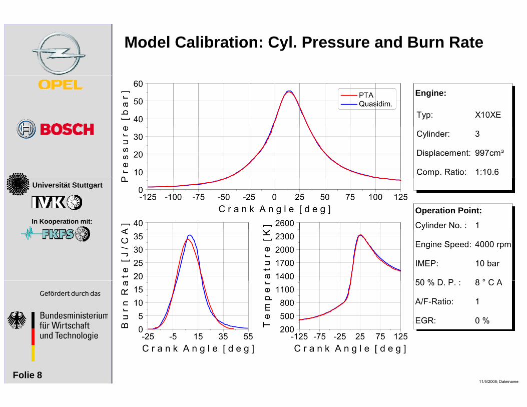
Model Calibration: Cyl. Pressure and Burn Rate
e [
b a
r ]40
50
60 PTA Quasidim.
Typ: X10XE
Engine:
P r e
s s
u r
e
10
20
30 Cylinder:
Displacement:
Comp. Ratio:
3 997cm³
1:10.6Universität Stuttgart
In Kooperation mit:
P
0
C r a n k A n g l e [ d e g ]-125 -100 -75 -50 -25 0 25 50 75 100 125
A ] 40 ] 2600 1Cylinder No. :
Operation Point:
t e [
J /
C A
20253035
a t u
r e
[ K
1400170020002300
4000 rpm
10 bar
8 ° C A
y
Engine Speed:
IMEP:
50 % D P
B u
r n R
a
05
1015
T e
m p
e r
200500800
11008 ° C A
1
0 %
50 % D. P. :
A/F-Ratio:
EGR:
11/5/2008; DateinameFolie 8
0
C r a n k A n g l e [ d e g ]-25 -5 15 35 55
200
C r a n k A n g l e [ d e g ]-125 -75 -25 25 75 125
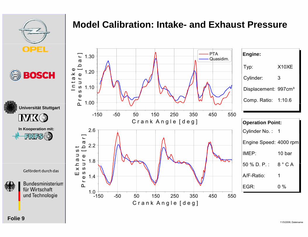
Model Calibration: Intake- and Exhaust Pressure
Typ: X10XE
Engine:
k e
e [
b a
r ]1.20
1.30 PTA Quasidim.
Cylinder:
Displacement:
Comp. Ratio:
3 997cm³
1:10.6
I n t
a k
P r e
s s
u r
e
1 00
1.10
Universität Stuttgart
In Kooperation mit: 1Cylinder No. :
Operation Point:
P 1.00
C r a n k A n g l e [ d e g ]-150 -50 50 150 250 350 450 550
2.6
4000 rpm
10 bar
8 ° C A
y
Engine Speed:
IMEP:
50 % D Ph a
u s
tu
r e [
b a
r ]
1.8
2.2
8 ° C A
1
0 %
50 % D. P. :
A/F-Ratio:
EGR:
E x
hP
r e s
s u
1.0
1.4
11/5/2008; DateinameFolie 9
1.0
C r a n k A n g l e [ d e g ]-150 -50 50 150 250 350 450 550
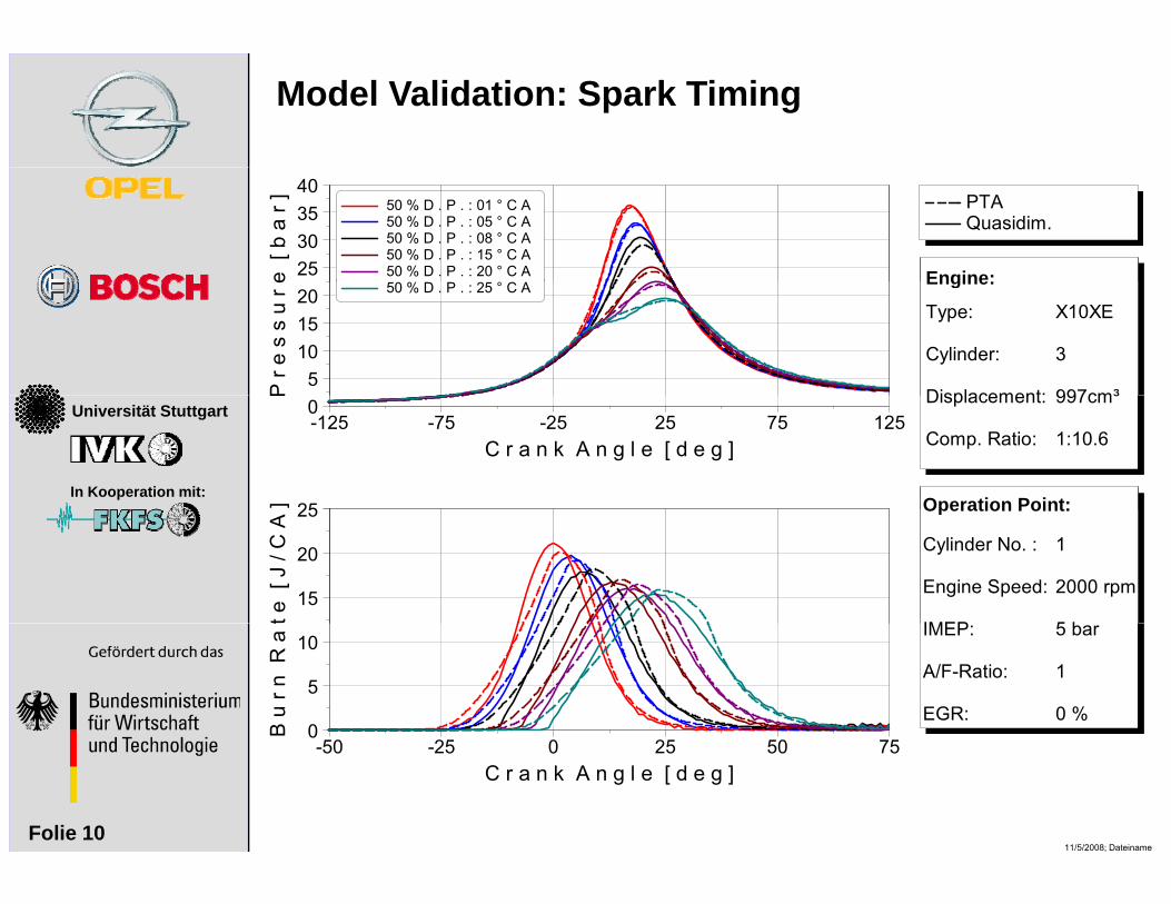
Model Validation: Spark Timing
Engine:
PTA Quasidim.
e [
b a
r ]25303540
50 % D . P . : 01 ° C A 50 % D . P . : 05 ° C A 50 % D . P . : 08 ° C A 50 % D . P . : 15 ° C A 50 % D . P . : 20 ° C A
Type:
Cylinder:
Displacement:
X10XE
3 997cm³
Engine:P
r e s
s u
r e
5101520 50 % D . P . : 25 ° C A
Universität Stuttgart
In Kooperation mit:
Displacement:
Comp. Ratio:
997cm³
1:10.6
Operation Point:
P
0
C r a n k A n g l e [ d e g ]-125 -75 -25 25 75 125
] 25
1
2000 rpm
5 b
Cylinder No. :
Engine Speed:
IMEP
Operation Point:
t e [
J /
C A
15
20
25
5 bar
1
0 %
IMEP:
A/F-Ratio:
EGR:
B u
r n R
a t
0
5
10
11/5/2008; DateinameFolie 10
0
C r a n k A n g l e [ d e g ]-50 -25 0 25 50 75
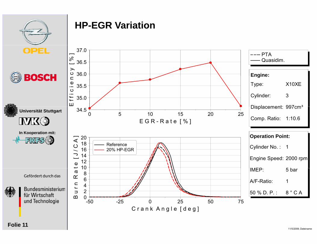
HP-EGR Variation
Engine:
PTA Quasidim.
c y
[ %
]36.0
36.5
37.0
Type:
Cylinder:
Displacement:
X10XE
3 997cm³
Engine:E
f f i
c i e
n
35.0
35.5
Universität Stuttgart
In Kooperation mit:
Displacement:
Comp. Ratio:
997cm³
1:10.6
Operation Point:
34.5
E G R - R a t e [ % ]0 5 10 15 20 25
] 20
1
2000 rpm
5 b
Cylinder No. :
Engine Speed:
IMEP
Operation Point:
t e [
J /
C A
101214161820
Reference 20% HP-EGR
5 bar
1
8 ° C A
IMEP:
A/F-Ratio:
50 % D. P. :
B u
r n R
a t
02468
10
11/5/2008; DateinameFolie 11
0
C r a n k A n g l e [ d e g ]-50 -25 0 25 50 75

Phlegmatic EnginePhlegmatic Engine: Theory• OP of high TPR can be shifted to lower (wider turbine neck square area)
Lower exhaust gas back pressure
Hi h i ffi i ( d d PMEP)
Better cylinder filling due to reduced internal EGR
0.8
Higher engine efficiency (reduced PMEP)
• Worse transient behavior of the engine can be compensated by e-motor
Universität Stuttgart
In Kooperation mit: w R
a t
i o
0 6
0.7
M a
s s
F l
o
0.5
0.6
T u
r b i
n e
M
0.3
0.4
1 8 0 m m 2 2 0 0 m m 2 2 4 0 m m 2
11/5/2008; DateinameFolie 12
T
0.2
T u r b i n e P r e s s u r e R a t i o1.0 1.5 2.0 2.5 3.0
Δ Π t2 8 0 m m 2
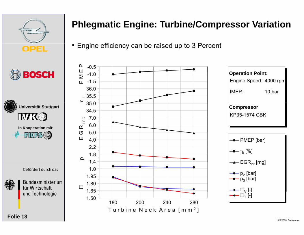
Phlegmatic Engine: Turbine/Compressor Variation
E i ffi i b i d t 3 P t
Operation Point:E P
1 0-0.5
• Engine efficiency can be raised up to 3 Percent
Operation Point:4000 rpm
10 bar
Engine Speed:
IMEP:
P M
-1.5-1.0
η i
35 035.536.0
Universität Stuttgart
In Kooperation mit:
CompressorKP35-1574 CBK
34.535.0
G R
i n t
5 06.07.0
PMEP [bar]
ηi [%]
EGR [mg]
E G
4.05.0
p 1 41.82.2
EGRint [mg]
p2 [bar] p3 [bar]
ΠV [-]
1.01.4
Π
1 651.801.95
11/5/2008; DateinameFolie 13
V [ ] ΠT [-]
T u r b i n e N e c k A r e a [ m m 2 ]180 200 240 280
1.501.65
Universität Stuttgart
In Kooperation mit:
GT Drive Hybrid Model
11/5/2008; DateinameFolie 14
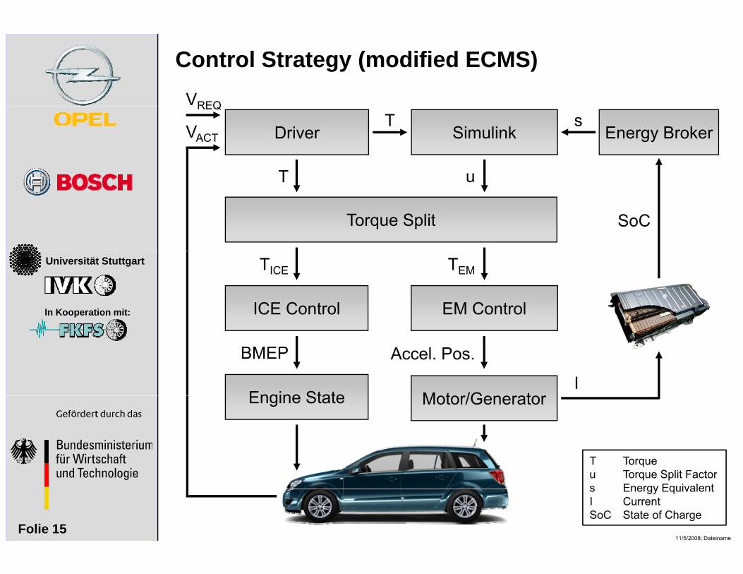
Control Strategy (modified ECMS)VREQ
Simulink Energy BrokerDriver
T u
T sREQ
VACT
Torque Split
T u
SoC
Universität Stuttgart
In Kooperation mit: ICE Control EM Control
TICE TEM
Engine State Motor/Generator
BMEP Accel. Pos.
IEngine State Motor/Generator
T Torque
11/5/2008; DateinameFolie 15
u Torque Split Factors Energy EquivalentI CurrentSoC State of Charge
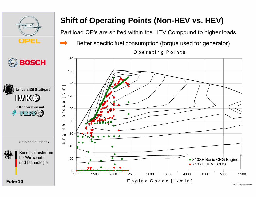
Shift of Operating Points (Non-HEV vs. HEV)Part load OP's are shifted within the HEV Compound to higher loads
O p e r a t i n g P o i n t s180
Better specific fuel consumption (torque used for generator)
] 140
160
Universität Stuttgart
In Kooperation mit: q u
e [
N m
]
100
120
g i n
e T
o r
60
80
E n
g
20
40
X10XE Basic CNG Engine
11/5/2008; DateinameFolie 16
0
E n g i n e S p e e d [ 1 / m i n ]1000 1500 2000 2500 3000 3500 4000 4500 5000 5500
X10XE Basic CNG Engine X10XE HEV ECMS
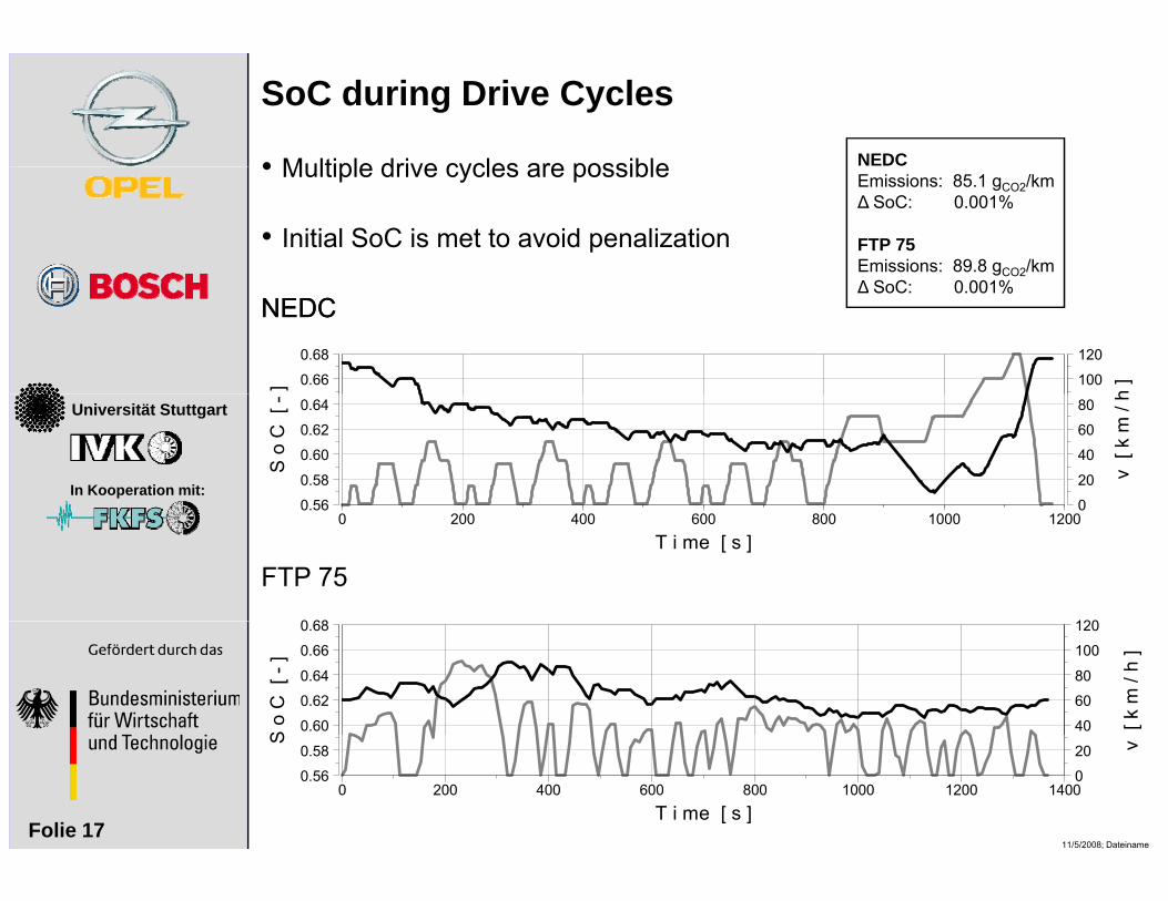
SoC during Drive CyclesNEDC• Multiple drive cycles are possible Emissions: 85.1 gCO2/km ∆ SoC: 0.001%
FTP 75Emissions: 89.8 gCO2/km∆ S C 0 001%
• Multiple drive cycles are possible
• Initial SoC is met to avoid penalization
h ]100
120
] 0.66
0.68
∆ SoC: 0.001% NEDCNEDC
Universität Stuttgart
In Kooperation mit:
v [
k m
/ h
0
20
40
60
80
S o
C [
-
0 56
0.58
0.60
0.62
0.64
00.56
T i me [ s ]0 200 400 600 800 1000 1200
1200 68
FTP 75
[ k m
/ h
]
40
60
80
100
120
S o
C [
- ]
0.60
0.62
0.64
0.66
0.68
11/5/2008; DateinameFolie 17
v
0
20
S
0.56
0.58
T i me [ s ]0 200 400 600 800 1000 1200 1400
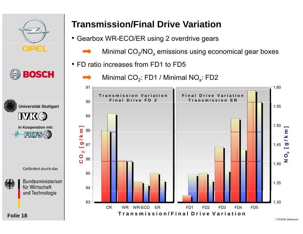
Transmission/Final Drive Variation• Gearbox WR-ECO/ER using 2 overdrive gears
• FD ratio increases from FD1 to FD5
Minimal CO2/NOx emissions using economical gear boxes
1.60
90
91
T r a n s m i s s i o n V a r i a t i o nF i n a l D r i v e F D 2
F i n a l D r i v e V a r i a t i o nT r a n s m i s s i o n E R
Minimal CO2: FD1 / Minimal NOx: FD2
Universität Stuttgart
In Kooperation mit:
m ]1.50
1.55
m ]
88
89
90
N O
x [ g
/ k
m
1.45
C O
2 [
g / k
m
86
87
N
1.35
1.40C
84
85
11/5/2008; DateinameFolie 18
1.3083
T r a n s m i s s i o n / F i n a l D r i v e V a r i a t i o nCR WR WR-ECO ER FD1 FD2 FD3 FD4 FD5

Thank you for your kind Universität Stuttgart
In Kooperation mit: AttentionAttention
11/5/2008; DateinameFolie 19