
Optimization & Control of PMSM Based Wind Energy Using...
7
International Journal of Science, Engineering and Technology Research (IJSETR), Volume 4, Issue 5, May 2015 1702 ISSN: 2278 – 7798 All Rights Reserved © 2015 IJSETR Abstract— In recent years, the increasing concerns to the environmental issues and the limited availability of conventional fossil fuels lead to rapid research and development for more sustainable and alternative electrical sources. Wind energy, as one of the most prominent renewable energy sources, is gaining increasing significance throughout the world. In this paper, a design fuzzy logic controller for a variable speed permanent magnet wind generator connected to a grid system is proposed. A new current control method of grid side conversion is developed by integrating the fuzzy controller, in which both active and reactive power, delivered to a power grid system, is controlled effectively. The fuzzy logic controller is designed to adjust the gain parameters of the PI controllers under any operating conditions, so that the dynamic stability is enhanced. The simulations have been performed using Matlab. Simulation results prove the excellent performance of fuzzy control unit as improving power quality and stability of wind turbine. Index Terms— PMSM; Fuzzy Logic Controller; PI Controller; Wind Energy; Renewable Energy. I. INTRODUCTION The global demand for electrical energy and fossil fuel is increasing at breath taking pace worldwide. Whilst demand is increasing, the days of overcapacity in electricity production are coming to an end. Many older power plants will soon reach to the end of their working lives. About half of the estimated capacity will be required to replace the existing aging power plants. The world may have to face a severe energy crisis in future in the absence of suitable precautionary measures, especially when there is already shortage of the fossil fuels widely used for power generation. The fossil fuels provides about three quarters of the world’s energy. The burning of fossil fuels produces lot of carbon dioxide, one of the main greenhouse gases, which is also considered as the main culprit for global warming and other environmental hazards like melting of the polar ice caps, flooding of low-lying land, storms, droughts and violent changes in weather patterns. Considering all these problems associated with fossil fuels, there is sudden need of the more efficient ways the world produces and consumes energy. Alongside the more efficient generation and use of energy, renewable sources of energy offer the great potential for deep cuts in carbon dioxide emissions. Despite the global abundance of renewable energy resources, renewable energy generation capacity represents merely 3% of the world’s installed power capacity. Since the past decade, however, there has been a renewed interest in many countries on renewable energy for power generation. The wind power generation is rapidly becoming competitive with conventional fossil fuel sources and already today is at par with new coal or gas fired power stations. The wind turbine design objectives have changed over the past decade from being convention-driven to being optimized driven within the operating regime and market environment. The wind turbines are growing in size, designs are progressing from fixed speed, stall-controlled having drive trains with gearboxes, to become pitch controlled, variable speed and with or without gearboxes. The advancement in power electronics devices further supports the trend toward variable speed turbines. Today, the wind turbines in the market have a variety of innovative concepts, with proven technology for both generators and power electronics interface. However, the increasing penetration of large wind farms into electrical power systems also poses different kind of challenges due to their intermittent nature. This inspires the designers to develop both custom generators and power electronics devices with sophisticated modern control system strategies. Recently, variable-speed permanent magnet synchronous generator (PMSG) based wind energy systems are becoming more attractive in comparison to fixed-speed wind energy system. In the variable-speed generation system, the wind turbine can be operated at maximum power operating points over a wide speed range by adjusting the shaft speed optimally. Moreover, the use of Permanent Magnet reduces size, and weight of overall wind energy system, as there is no need of field winding and its excitation system. The absence of rotor winding also reduces heat dissipation in the rotor and hence improves the overall efficiency. This kind of configuration also find special favour for off-shore wind application, where the geared doubly fed induction generator requires regular maintenance due to tearing-wearing in brushes and gear box. To perform maximum power point tracking at different wind speeds, the variable speed operation of PMSG is required. For the variable speed operation of PMSG, generally vector control is preferred as it allows the independent torque and field control just like a simple DC motor control. The vector control of PMSG essentially requires the rotor position and speed information. For this purpose, usually shaft mounted speed and position sensors are used, resulting into additional cost and complexity of the system. In order to eliminate the sensors and their associated problems, a fuzzy logic controller (FLC) is proposed for rotor position and speed estimation over wide range of speed operation. In the proposed work a PMSG based Wind energy system is modelled for grid connected system. In grid connected system, the fault ride through capability of wind energy Optimization & Control of PMSM Based Wind Energy Using PI and Fuzzy Logic Controller Munendra Pratap Singh, Er. Vinay Kumar Tripathi
Transcript of Optimization & Control of PMSM Based Wind Energy Using...

International Journal of Science, Engineering and Technology Research (IJSETR), Volume 4, Issue 5, May 2015
1702
ISSN: 2278 – 7798 All Rights Reserved © 2015 IJSETR
Abstract— In recent years, the increasing concerns to the
environmental issues and the limited availability of conventional
fossil fuels lead to rapid research and development for more
sustainable and alternative electrical sources. Wind energy, as
one of the most prominent renewable energy sources, is gaining
increasing significance throughout the world.
In this paper, a design fuzzy logic controller for a variable
speed permanent magnet wind generator connected to a grid
system is proposed. A new current control method of grid side
conversion is developed by integrating the fuzzy controller, in
which both active and reactive power, delivered to a power grid
system, is controlled effectively. The fuzzy logic controller is
designed to adjust the gain parameters of the PI controllers
under any operating conditions, so that the dynamic stability is
enhanced. The simulations have been performed using Matlab.
Simulation results prove the excellent performance of fuzzy
control unit as improving power quality and stability of wind
turbine.
Index Terms— PMSM; Fuzzy Logic Controller; PI
Controller; Wind Energy; Renewable Energy.
I. INTRODUCTION
The global demand for electrical energy and fossil fuel is
increasing at breath taking pace worldwide. Whilst demand is
increasing, the days of overcapacity in electricity production
are coming to an end. Many older power plants will soon
reach to the end of their working lives. About half of the
estimated capacity will be required to replace the existing
aging power plants. The world may have to face a severe
energy crisis in future in the absence of suitable precautionary
measures, especially when there is already shortage of the
fossil fuels widely used for power generation. The fossil fuels
provides about three quarters of the world’s energy. The
burning of fossil fuels produces lot of carbon dioxide, one of
the main greenhouse gases, which is also considered as the
main culprit for global warming and other environmental
hazards like melting of the polar ice caps, flooding of
low-lying land, storms, droughts and violent changes in
weather patterns. Considering all these problems associated
with fossil fuels, there is sudden need of the more efficient
ways the world produces and consumes energy. Alongside the
more efficient generation and use of energy, renewable
sources of energy offer the great potential for deep cuts in
carbon dioxide emissions. Despite the global abundance of
renewable energy resources, renewable energy generation
capacity represents merely 3% of the world’s installed power
capacity. Since the past decade, however, there has been a
renewed interest in many countries on renewable energy for
power generation.
The wind power generation is rapidly becoming competitive
with conventional fossil fuel sources and already today is at
par with new coal or gas fired power stations. The wind
turbine design objectives have changed over the past decade
from being convention-driven to being optimized driven
within the operating regime and market environment. The
wind turbines are growing in size, designs are progressing
from fixed speed, stall-controlled having drive trains with
gearboxes, to become pitch controlled, variable speed and
with or without gearboxes. The advancement in power
electronics devices further supports the trend toward variable
speed turbines. Today, the wind turbines in the market have a
variety of innovative concepts, with proven technology for
both generators and power electronics interface. However, the
increasing penetration of large wind farms into electrical
power systems also poses different kind of challenges due to
their intermittent nature. This inspires the designers to
develop both custom generators and power electronics
devices with sophisticated modern control system strategies.
Recently, variable-speed permanent magnet synchronous
generator (PMSG) based wind energy systems are becoming
more attractive in comparison to fixed-speed wind energy
system. In the variable-speed generation system, the wind
turbine can be operated at maximum power operating points
over a wide speed range by adjusting the shaft speed
optimally. Moreover, the use of Permanent Magnet reduces
size, and weight of overall wind energy system, as there is no
need of field winding and its excitation system. The absence
of rotor winding also reduces heat dissipation in the rotor and
hence improves the overall efficiency. This kind of
configuration also find special favour for off-shore wind
application, where the geared doubly fed induction generator
requires regular maintenance due to tearing-wearing in
brushes and gear box.
To perform maximum power point tracking at different wind
speeds, the variable speed operation of PMSG is required. For
the variable speed operation of PMSG, generally vector
control is preferred as it allows the independent torque and
field control just like a simple DC motor control. The vector
control of PMSG essentially requires the rotor position and
speed information. For this purpose, usually shaft mounted
speed and position sensors are used, resulting into additional
cost and complexity of the system. In order to eliminate the
sensors and their associated problems, a fuzzy logic controller
(FLC) is proposed for rotor position and speed estimation
over wide range of speed operation.
In the proposed work a PMSG based Wind energy system is
modelled for grid connected system. In grid connected
system, the fault ride through capability of wind energy
Optimization & Control of PMSM Based Wind
Energy Using PI and Fuzzy Logic Controller
Munendra Pratap Singh, Er. Vinay Kumar Tripathi
International Journal of Science, Engineering and Technology Research (IJSETR), Volume 4, Issue 5, May 2015
1703
ISSN: 2278 – 7798 All Rights Reserved © 2015 IJSETR
system is demonstrated under grid voltage sag/swell
conditions.
Another objective is to develop an advance controller for grid
side inverter. Since the inverter works under highly
fluctuating operating conditions, it is not possible to set the
optimal value of gains for the conventional
proportional-integral (PI) regulator. This may lead to false
operation of inverter.
The main objective is to achieve smooth operation of grid side
inverter, where the conventional PI controller may fail due to
the rapid change in the dynamics of the overall system. The
combined capability of PI-fuzzy controller in handling the
uncertainties and learning from the processes is proved to be
advantageous while controlling the inverter under fluctuating
operating conditions.
II. MODEL OF WIND TURBINE
The static characteristic of the turbine (output as a function of
wind speed) can be described by the relationship between the
total power and mechanical energy of the wind:
where ρ is the air density (1,225 kg/m3), Rturbine is then rotor
radius (m), vwind is the wind speed (m/s). It is impossible to
extract all the kinetic energy of wind, so it extracts a fraction
of the power of wind as shown in (2) as the power coefficient
Cp.
Pm is the mechanical power of the wind (Nm/s). The
maximum power coefficient CpM is 0.59. This coefficient is
also known as Betz limit. It can be expressed in terms of
reduced velocity λ and angle of light θ: Cp = Cp (λ, θ).
If W is the rotor speed, the reduced speed λ is defined:
Assuming a constant wind speed vwind, the reduced speed λ
varies proportionally to the rotor speed [10]. The maximum
value of Cp is generally obtained for values of λ around 8 to 9
(when the tip of the movements of blade is 8 to 9 times faster
than the wind). On modern wind turbines, it is possible to
adjust the angle of the blades through a control mechanism
[11]. If Cp-λ curve is known for a specific wind with a radius
of turbine rotor Rturbine, it is easy to construct the curve of Cp as
a function of rotational speed Ω for a wind speed vwind. The
output torque of the turbine is calculated :
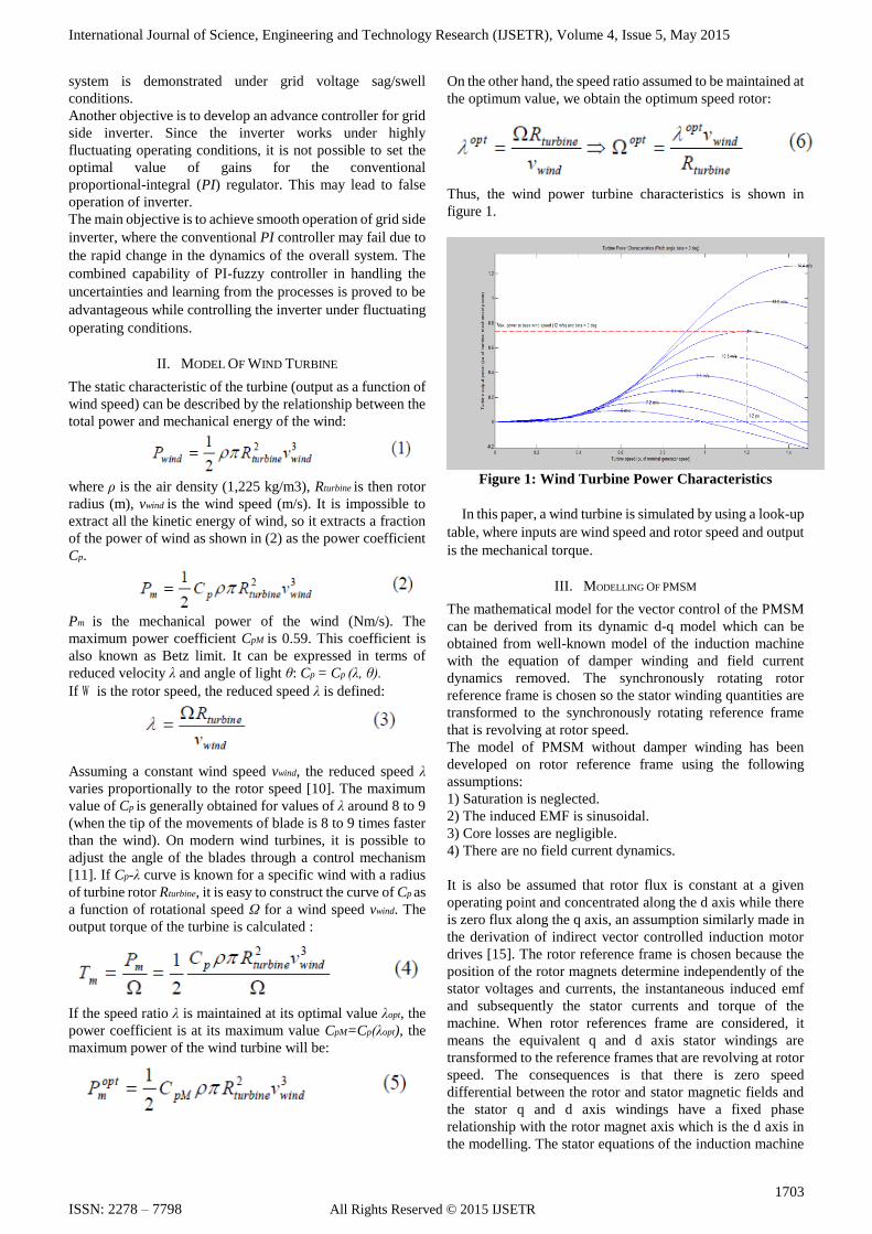
If the speed ratio λ is maintained at its optimal value λopt, the
power coefficient is at its maximum value CpM=Cp(λopt), the
maximum power of the wind turbine will be:
On the other hand, the speed ratio assumed to be maintained at
the optimum value, we obtain the optimum speed rotor:
Thus, the wind power turbine characteristics is shown in
figure 1.
Figure 1: Wind Turbine Power Characteristics
In this paper, a wind turbine is simulated by using a look-up
table, where inputs are wind speed and rotor speed and output
is the mechanical torque.
III. MODELLING OF PMSM
The mathematical model for the vector control of the PMSM
can be derived from its dynamic d-q model which can be
obtained from well-known model of the induction machine
with the equation of damper winding and field current
dynamics removed. The synchronously rotating rotor
reference frame is chosen so the stator winding quantities are
transformed to the synchronously rotating reference frame
that is revolving at rotor speed.
The model of PMSM without damper winding has been
developed on rotor reference frame using the following
assumptions:
1) Saturation is neglected.
2) The induced EMF is sinusoidal.
3) Core losses are negligible.
4) There are no field current dynamics.
It is also be assumed that rotor flux is constant at a given
operating point and concentrated along the d axis while there
is zero flux along the q axis, an assumption similarly made in
the derivation of indirect vector controlled induction motor
drives [15]. The rotor reference frame is chosen because the
position of the rotor magnets determine independently of the
stator voltages and currents, the instantaneous induced emf
and subsequently the stator currents and torque of the
machine. When rotor references frame are considered, it
means the equivalent q and d axis stator windings are
transformed to the reference frames that are revolving at rotor
speed. The consequences is that there is zero speed
differential between the rotor and stator magnetic fields and
the stator q and d axis windings have a fixed phase
relationship with the rotor magnet axis which is the d axis in
the modelling. The stator equations of the induction machine
International Journal of Science, Engineering and Technology Research (IJSETR), Volume 4, Issue 5, May 2015
1704
ISSN: 2278 – 7798 All Rights Reserved © 2015 IJSETR
in the rotor reference frames using flux linkages are taken to
derive the model of the PMSM as shown in Fig.2:
Fig.2: PM machine synchronously rotating d-q reference
frame.
So an PM machine is described by the following set of general
equations:
Voltage equations are given by:
Vd = Rsid – ωrλq + (1)
Vq = Rsiq – ωrλd + (2)
Flux linkages are given by
λq = Lqiq (3)
λd = Ldid + λf (4)
Substituting (3) & (4) into (1) & (2), we get
Vq = Rsiq + ωr(Ldid + λf ) + (Lqiq) (5)
Vd = Rsid - ωrLqiq + (Ldid + λf ) (6)
Arranging equations (5) and (6) in matrix
form
The developed torque motor is being given by
Te = 3/2 (P/2) (λdiq – λqid) (8)
Te = 3/4 P[λfiq + (Ld - Lq) iqid] (9)
The mechanical torque equation is
Te = TL + Bωm + J (10)
Solving for rotor mechanical speed from (10), we get
ωm = ( Te – TL- Bωm / J ) dt (11)
and rotor electrical speed is ωr = ωm(P/2). (12)
3.1. Park Transformation and Dynamic d-q Modelling:
The dynamic d-q modelling is used for the study of motor
during transient and steady state. It is done by converting the
three phase voltages and currents to dqo variables by using
Parks transformation [16]. Converting the phase voltages
variables Vabc to Vdqo variables in rotor reference frame the
following equations are obtained:
In contrast, Vdqo can be converted to Vabc as:
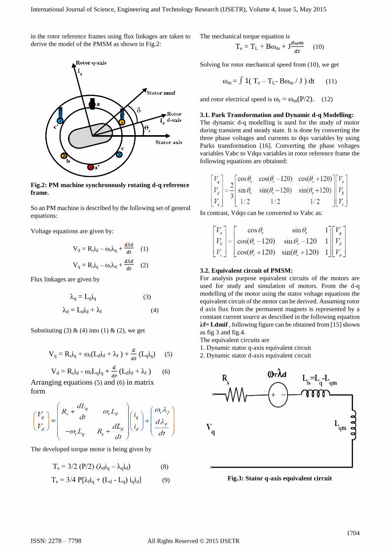
3.2. Equivalent circuit of PMSM:
For analysis purpose equivalent circuits of the motors are
used for study and simulation of motors. From the d-q
modelling of the motor using the stator voltage equations the
equivalent circuit of the motor can be derived. Assuming rotor
d axis flux from the permanent magnets is represented by a
constant current source as described in the following equation
λf= Ldmif , following figure can be obtained from [15] shown
as fig 3 and fig.4.
The equivalent circuits are
1. Dynamic stator q-axis equivalent circuit
2. Dynamic stator d-axis equivalent circuit
Fig.3: Stator q-axis equivalent circuit
International Journal of Science, Engineering and Technology Research (IJSETR), Volume 4, Issue 5, May 2015
1705
ISSN: 2278 – 7798 All Rights Reserved © 2015 IJSETR
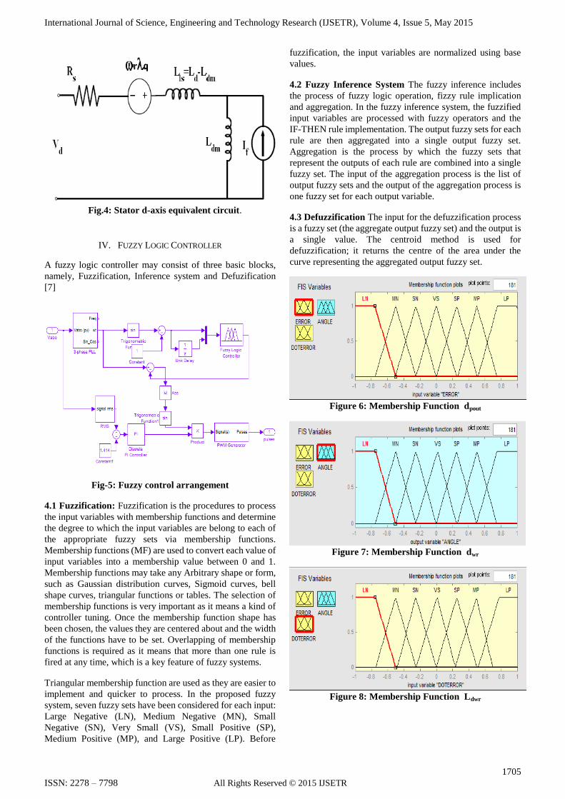
Fig.4: Stator d-axis equivalent circuit.
IV. FUZZY LOGIC CONTROLLER
A fuzzy logic controller may consist of three basic blocks,
namely, Fuzzification, Inference system and Defuzification
[7]
Fig-5: Fuzzy control arrangement
4.1 Fuzzification: Fuzzification is the procedures to process
the input variables with membership functions and determine
the degree to which the input variables are belong to each of
the appropriate fuzzy sets via membership functions.
Membership functions (MF) are used to convert each value of
input variables into a membership value between 0 and 1.
Membership functions may take any Arbitrary shape or form,
such as Gaussian distribution curves, Sigmoid curves, bell
shape curves, triangular functions or tables. The selection of
membership functions is very important as it means a kind of
controller tuning. Once the membership function shape has
been chosen, the values they are centered about and the width
of the functions have to be set. Overlapping of membership
functions is required as it means that more than one rule is
fired at any time, which is a key feature of fuzzy systems.
Triangular membership function are used as they are easier to
implement and quicker to process. In the proposed fuzzy
system, seven fuzzy sets have been considered for each input:
Large Negative (LN), Medium Negative (MN), Small
Negative (SN), Very Small (VS), Small Positive (SP),
Medium Positive (MP), and Large Positive (LP). Before
fuzzification, the input variables are normalized using base
values.
4.2 Fuzzy Inference System The fuzzy inference includes
the process of fuzzy logic operation, fizzy rule implication
and aggregation. In the fuzzy inference system, the fuzzified
input variables are processed with fuzzy operators and the
IF-THEN rule implementation. The output fuzzy sets for each
rule are then aggregated into a single output fuzzy set.
Aggregation is the process by which the fuzzy sets that
represent the outputs of each rule are combined into a single
fuzzy set. The input of the aggregation process is the list of
output fuzzy sets and the output of the aggregation process is
one fuzzy set for each output variable.
4.3 Defuzzification The input for the defuzzification process
is a fuzzy set (the aggregate output fuzzy set) and the output is
a single value. The centroid method is used for
defuzzification; it returns the centre of the area under the
curve representing the aggregated output fuzzy set.
Figure 6: Membership Function dpout
Figure 7: Membership Function dwr
Figure 8: Membership Function Ldwr

International Journal of Science, Engineering and Technology Research (IJSETR), Volume 4, Issue 5, May 2015
1706
ISSN: 2278 – 7798 All Rights Reserved © 2015 IJSETR
Fig-9: Rule view of the next fuzzy control system
Fig-10 surface view of the next fuzzy control system
V. MODELLING & RESULT
In this proposed model, a 3-phase permanent magnet
synchronous machine with sinusoidal back EMF is
implemented. The sinusoidal machine is modelled in the dq
rotor reference frame. Stator windings are connected in wye
to an internal neutral point. The rest system parameter values
are tabulated in appendix A.
Figure 11: Complete model of wind energy with PI and
Fuzzy Controller
In wind turbine block implements a variable pitch wind
turbine model. The performance coefficient Cp of the turbine
is the mechanical output power of the turbine divided by wind
power and a function of wind speed, rotational speed, and
pitch angle (beta). Cp reaches its maximum value at zero beta.
The base generator speed is the 1.2 p.u. For a synchronous
generator, the base speed is the synchronous speed. For a
permanent-magnet generator, the base speed is defined as the
speed producing nominal voltage at no load.
The blade pitch angle is zero degree and the wind speed is
12m/s. the nominal output mechanical power is 150 x 103 W.
In this model a PLL is also implemented. The Phase Locked
Loop (PLL) system can be used to synchronize on a set of
variable frequency, three-phase sinusoidal signals. If the
Automatic Gain Control is enabled, the input (phase error) of
the PLL regulator is scaled according to the input signal
magnitude.
PMSG Values
Rated Speed 4250 rpm
Stator Resistence 1.6 ohm
Magnetic flux Linkage 0.1852 wb
Stator inductance (Ld, Lq) 0.006365, 0.006365 mH
Rated Torque 3.2 Nm
Torque Constant 0.5556 Nm
Friction Factor 5.369 * 10-005
Appendix : A
The output results are

International Journal of Science, Engineering and Technology Research (IJSETR), Volume 4, Issue 5, May 2015
1707
ISSN: 2278 – 7798 All Rights Reserved © 2015 IJSETR
Figure 12: Waveform of Permanent Magnet synchronous
machine : (i) Electromagnetic Torque Te, (ii) Rotor Speed
rad/sec and (iii) waveform of Stator Current in Ampere.
Figure 13: Waveform of active and reactive power at
sending end.
Figure 14: Waveform of active and reactive power at
receiving end
Figure 15: Waveform of current at sending end
Figure 16: Waveform of current at receiving end
Figure 17: waveform of voltage at sending end

International Journal of Science, Engineering and Technology Research (IJSETR), Volume 4, Issue 5, May 2015
1708
ISSN: 2278 – 7798 All Rights Reserved © 2015 IJSETR
Figure 18: waveform of voltage at receiving end.
VI. CONCLUSION
In this paper, a new Fuzzy-PI controller for variable speed
permanent magnet wind generators connected to a power grid
is proposed and investigated in order to enhance its dynamic
performances. The controller combines fuzzy logic with a
classical PI controller in order to adjust the PI gains online.
The stabilizing effect of the proposed PMSG system on the
fixed speed wind generators is also investigated. The results
show that the proposed Fuzzy-PI controller is very effective in
improving the transient stability of overall wind farm systems
during temporary and permanent fault conditions. The steady
state performance of the proposed system is analyzed using
variable wind speed data, and it is demonstrated that the
terminal voltage of wind farm under randomly varying wind
speed can be controlled constantly.
REFERENCES
[1]. A.Morales and J.C. Maun: ―Power quality
responsibilities by grid impedance assessment at a wind
power production‖, CIRED, Barcelona, Spain, 12-15
May 2003.
[2]. AWEA Electrical guide to utility scale wind turbines,
March 2005.
[3]. R. Andersen, L. Xu, and P. J. Horton, ―Topologies for
VSC transmission,‖ Power Eng. J., vol. 16, pp.
142–150, Jun. 2002.
[4]. Dr. Rakesh Saxena, Sonali Barod, ―Analysis of power
Quality in power Supplies‖, International Journal of
Scientific & Engineering Research Volume 3, Issue 8,
August-2012
[5]. G. Venkataramanan and B. K. Johnson, ―A
superconucting dc transmission system based on VSC
transmission technologies,‖ IEEE Trans.Appl.
Superconduct., pt. 2, vol. 13, no. 2, pp. 1922–1925, Jun.
2003.
[6]. H.Polinder, F .F .A. van der pijl, G.J. de Vilder, and P.J.
Tavner, ―Comparison of Direct Drive and geared
generator concepts for wind turbines,‖IEEE
Trans.Energy Convers., vol.21, no3, pp.725- 733,sep
2006.
[7]. Jay Verma, Yogesh Tiwari, Anup Mishra, Nirbhay
Singh International Journal of Recent Technology and
Engineering (IJRTE) ISSN: 2277-3878, Volume-2,
Issue-6, January 2014 33 Published By: Blue Eyes
Intelligence Engineering & Sciences Publication Pvt.
Ltd. Performance, Analysis and Simulation of Wind
Energy Conversion System Connected With Grid.
[8]. Jonathan D.Rose and Ian A.Hiskens, ‖Challenges of
Integrating Large Amounts of Wind Power‖,1st Annual
IEEE systems conference,USA,April 9-12,2007.
[9]. Kenneth.E.Okedu ― Effects of drive train model
parameters on a variable speed wind turbine.‖
International journal of renewable energy research , vol
2 , no 2 ,2012.
[10]. Molinas M, Suul JA and Undeland T (2008). Low
voltage ride through of wind farms with cage generators:
STATCOM versus SVC. IEEE Trans Power.
[11]. Muyeen SM, Mannan MA, Ali MH, Takahashi R,
Murata T and Tamura J (2006). Stabilization of wind
turbine generator system by STATCOM. IEEJ
Transactions on Power and Energy 126-B(10) 1073-82.
[12]. Muyeen SM, Takahashi R, Ali MH, Murata T and
Tamura J (2000) Transient stability augmentation of
power system including wind farms by using ECS. IEEE
Transactions on Power Systems 23(3) 1179-87.
[13]. N.G.Hingorani and Laszlo gyugyi, ”Understanding
FACTS Concepts and Technology of FACTS”,Standard
Publishers Distributors,2000.
[14]. Power Quality issues standards and guide lines‖, IEEE
[15]. S. W. Mohod and M. V. Aware,‖ Power quality issues &
its mitigation technique in wind energy conversion,‖
inProc. of IEEE Int. Conf. Quality Power & Harmonic,
Wollongong, Australia, 2008
BIOGRAPHY
.
Munendra Pratap Singh Belongs to UP received
his Bachelor of Technology degree from Ideal
Institute of technology, Ghaziabad in 2013. He is
pursuing his M.Tech in Electrical Engg. (Power
System) from SHIATS, Allahabad, UP-India. His
field of interest includes power quality,
embedded system, programmable logic controller
and electric drives.
Er. Vinay kumar tripathi belongs to district
Allahabad of uttar pradesh. He received his bachelor
of technology degree from UCER, allahabad in
2003. He obtained his M. Tech. in electrical eng.
(control & instrumentation) from MNNIT,
allahabad, Uttar pradesh in 2006 and pusuing Phd.
from sam higginbottom institute of agriculture
technology and sciences university (SHIATS),
allahabad, up, india. He is having 10 years’
experience in teaching and presently working as
asst. prof. in electrical engineering department,
SSET, SHIATS, allahabad. His field of interest
includes control and instrumentation, multiphase
system, power quality and electric drive