Operations Manual for WM-WM1 - rgf.com · Operations Manual for Model WM-WM1 Overview 1 Overview...
117
Operations Manual for WM-WM1 By RGF Environmental Group, Inc
Transcript of Operations Manual for WM-WM1 - rgf.com · Operations Manual for Model WM-WM1 Overview 1 Overview...

Operations Manual for
WM-WM1
By RGF Environmental Group, Inc

Copyright @ 1999 RGF Environmental Group Inc All rights reserved
1101 West 13th Street, Riviera Beach, Florida 33404 1-800-842-7771, FL/INT-561-848-1826, Fax-561-848-9454
www.rgf.com, e-mail: [email protected]

Operations Manual for WM-WM1
Table of Contents
Table of Contents i
Overview 1
Introduction ............................................................................................................................... 1 How to Use This Manual ........................................................................................................... 1 How This Manual Is Organized ................................................................................................. 2 Sources of Help .......................................................................................................................... 3
Shipment Inspection 1
Shipment Inspection .................................................................................................................. 1 Pre-Installation Checklist ........................................................................................................... 1
Safety 3
Labeling Conventions in This Manual ....................................................................................... 3 General Safety Issues ................................................................................................................. 4
Chapter 1: The WM-WM1 System 5
The Vision 2000 Concept .......................................................................................................... 5 The WasteManagement System ............................................................................................... 6 Unit Familiarization / Flow Diagram ......................................................................................... 6
Chapter 2: Installation 9
Installation Requirements .......................................................................................................... 9 Installation Procedure ................................................................................................................ 9
Equipment Placement ................................................................................................ 10 Main Drain Return Line ............................................................................................ 10 Main Electrical Connection ....................................................................................... 10 Centrifugal Coalescing Clarifier (CCC Tank) ........................................................... 10 Hydrocarbon Accumulator ........................................................................................ 10 Biosorb Series I ......................................................................................................... 11 Series II Equipment Skid ........................................................................................... 13 Series III Storage Tank .............................................................................................. 17
Chapter 3: System Startup and Operation 19
System Startup ......................................................................................................................... 19 System Operation ..................................................................................................................... 23
Centrifugal Coalescing Clarifier (CCC Tank ............................................................ 23 Biosorb Series I ......................................................................................................... 23 Series II Equipment Skid ........................................................................................... 23 Series III Storage Tank .............................................................................................. 24

Operations Manual for Model WM-WM1
Operational Notes .................................................................................................................... 25
Chapter 4: Preventative Maintenance Schedule 27
Overview .................................................................................................................................. 27 Required Tools and Supplies ................................................................................................... 27 Daily Maintenance ................................................................................................................... 28
Centrifugal Coalescing Clarifier (CCC Tank) ........................................................... 28
BIOSORB System Maintenance ............................................................................ 28 Weekly Maintenance .......................................................................................... 28 Series II Equipment Skid ........................................................................................... 29 Polishing Filters ......................................................................................................... 29 UV/O3 Catalytic Chambers ........................................................................................ 29
Weekly Maintenance ............................................................................................................... 30 Trenches, Sumps, Pits, and Clarifiers ........................................................................ 30 Y-Strainer .................................................................................................................. 30 Multi-Media Filter ..................................................................................................... 30 Polishing Filters ......................................................................................................... 31 Storage Tanks ............................................................................................................ 31
Monthly Maintenance .............................................................................................................. 32 UV/O3 Catalytic Chambers ........................................................................................ 32
As Required Maintenance ........................................................................................................ 33 Multi-Media Filter ..................................................................................................... 33 Programmable Auto BackFlush ................................................................................. 33
Winterizing the System ............................................................................................................ 34
Chapter 5: General Theory 35
Overview .................................................................................................................................. 35 Biosorb Series I System ........................................................................................................... 35
Biosorb Series I ......................................................................................................... 35 Series II Equipment Skid ......................................................................................................... 35
Process System .......................................................................................................... 35 Supply Header ........................................................................................................... 36 Continuous Flow Control System (CFC System) ...................................................... 36 CFC Pump ................................................................................................................. 36
Catalytic Oxidation Process (CO3P System) ............................................................. 36 UV/O3 Catalytic Chamber ........................................................................................ 37 Delivery Pump ........................................................................................................... 37
Chapter 6: Controlling Water Quality 38
Overview .................................................................................................................................. 38 pH / Alkalinity ......................................................................................................................... 39
pH .............................................................................................................................. 39 Total Alkalinity ......................................................................................................... 39
Oxidizers .................................................................................................................................. 40 Ozone ......................................................................................................................... 40 UltraViolet Light ....................................................................................................... 40
Cleaning Agents ....................................................................................................................... 40 Enviro-Control ........................................................................................................... 40 Water Conditioner-1 (WC-1) ..................................................................................... 41
Dissolved and Suspended Solids .............................................................................................. 41 Total Dissolved Solids (TDS) .................................................................................... 41 Total Suspended Solids (TSS) ................................................................................... 41

Operations Manual for WM-WM1
Chapter 7: Engineering Drawings 43
Outline ..................................................................................................................................... 43 Biosorb Series I ........................................................................................................................ 45 ................................................................................................................................................. 45 Series II Equipment Skid ......................................................................................................... 47 ................................................................................................................................................. 47 Series III Storage Tank ............................................................................................................ 49 Piping & Instrumentation Diagram .......................................................................................... 51 Electrical Ladder Diagram ....................................................................................................... 53 Electrical Diagram ................................................................................................................... 55
Chapter 8: Troubleshooting 57
Flow ......................................................................................................................................... 57 Electrical .................................................................................................................................. 59 Chemistry ................................................................................................................................. 60
Chapter 9: Replacement Parts 61
General Ordering Information ................................................................................................. 61 Replacement Parts List ............................................................................................................ 61
Filters and Parts ......................................................................................................... 61 Pumps and Parts ........................................................................................................ 61 Valves and Unions ..................................................................................................... 62 Misc. Parts ................................................................................................................. 62
Chapter 10: Sub-Component Manuals 63
GFI Reset ................................................................................................................................. 64 Process Pump ........................................................................................................................... 65 CFC System Pump ................................................................................................................... 69 Auto Backflush Timer ............................................................................................................. 80
System Warranty 89
Product Registration and Return Forms 96
Glossary of Terms 106


Operations Manual for Model WM-WM1 Overview 1
Overview
Introduction
About RGF
Congratulations on the purchase of your new RGF Waste Water Treatment System. For over 25 years RGF Environmental Group, Inc. has been the industry leader in industrial wash water treatment systems with thousands of installations worldwide.
RGF Environmental Group, Inc. is committed to helping industry comply with strict EPA regulations. Founded in 1985, RGF pioneered the development of heavy equipment zero discharge wash water recycling systems. Since then, RGF has continuously expanded to encompass the entire scopes of water treatment concerns of industry. Today RGF offers a variety of products and services that is among the widest available in the pollution control equipment industry.
How to Use This Manual
As with any piece of new equipment, the first thing you should do is obtain a complete understanding of the operation and maintenance of the system before you begin. The best way to do this is to read the manual and associated documentation sent with the unit well before it is scheduled to be installed. RGF has invested a great deal of effort to make our manuals as informative and user friendly as possible to make the task of learning about your new system as enjoyable as possible.

2 Overview Operations Manual for Model WM-WM1
How This Manual Is Organized This manual is divided into the following major sections.
Shipment Inspection/ Receipt Checklist: This section should be read immediately upon receipt of your system.
Safety: A description of the labeling conventions employed in the manual to
point out specific items relating to issues of personnel safety and proper operation of the system. General safety concerns and overall operational guidelines for the system.
Chapter 1: The WM-WM1 System Unit familiarization, basic system information and system flow
diagrams. Covers the overall concepts of the Vision 2000 UltraSorb System.
Chapter 2: Installation Provides important information to ensure proper equipment placement
and connection.
Chapter 3: System Startup and Operation Contains the steps required to properly start up your new system. The
Operating Instructions outline the normal course of action for the routine operation of the system.
Chapter 4: Preventative Maintenance Schedule Recommended periodicities for maintenance routines are located in this
section. Personnel who will be maintaining the unit should familiarize themselves fully with this section.
Chapter 5: General Theory A description of how the RGF WM-WM1 system actually separates,
clarifies and treats the waste stream. In depth explanations of the processes and supporting information to help operators understand the physics and chemistry of the system.
Chapter 6: Controlling Water Quality Without proper water chemistry control, even the most sophisticated
systems will fail to perform to expectations. This section covers important topics, which must be continually considered for proper system operation.

Operations Manual for Model WM-WM1 Overview 3
Chapter 7: Engineering Drawings Reference drawings and schematics of the system.
Chapter 8: Troubleshooting This section provides possible remedies for unusual operating
conditions that occur from time to time.
Chapter 9: Replacement Parts List A convenient source for locating part numbers and nomenclature of
commonly replaced items on the system.
Chapter 10: Sub-Component Manuals Additional literature provided on individual components of the system.
This section is useful for more detailed knowledge of technical specifications regarding a specific sub-component.
Sources of Help
If you are unable to answer questions you have about your system from the information in this manual, RGF provides the following additional sources of help.
1) Your local RGF Licensed Distributor. He has a service support staff that is trained on all systems.
2) RGF Web Site Help Page provides answers to commonly asked questions and late breaking information concerning system operation and maintenance.
http://www.rgf.com
3) If you still have questions or have comments, the RGF Service Department can be contacted by e-mail at:
e-mail: [email protected]
E-mail queries receive first priority through the Service Department. Please include as much information as possible so our service staff can quickly return an answer.


Operations Manual for Model WM-WM1 Shipment Inspection 1
Shipment Inspection
Shipment Inspection
Immediately upon receipt of the WM-WM1 System, you are responsible as the purchaser to take the shipping containers off the truck and inspect the equipment, storage tanks and parts for damage.
IF ANY VISIBLE DAMAGE TO THE EQUIPMENT IS EVIDENT:
Notify the driver for the courier company immediately and write on the Bill of Lading what is damaged or missing.
Call RGF immediately at (561)-848-1826 or FAX (561)-848-9454 a copy of the Bill of Lading with damage or missing items to RGF.
Pre-Installation Checklist
Remove the RGF PACKING SLIP and the BILL OF LADING. Verify the condition and presence of all the parts and components found on the pallets and skids. Remove the LOOSE PARTS CHECKLIST from inside of the LOOSE PARTS BOX and verify the condition and presence of all the parts and components within the box. If any of the items are missing, please contact your distributor immediately or RGF at (561)-848-1826 or FAX (561)-848-9454.


Operations Manual for Model WM-WM1 Safety 3
Safety
Labeling Conventions in This Manual
Certain information contained in this manual is VERY IMPORTANT. In addition, there are varying degrees of importance of this special information. Since most of the special information regards safety related issues, this section explains the conventions used throughout this manual. The following information explains the various conventions used to highlight important information
This statement directly regards an immediate RISK TO LIFE.
This designation, along with its associated graphical representation, denotes information that must be completely understood and heeded in order to prevent Serious Personal Harm or Significant Environmental Consequences.
This designation brings special attention to information that sensitizes the reader to the importance of following the instruction carefully. Typically used for information that reduces the risk of equipment damage or increases personal safety of the operator.
Note:
This designation clarifies or brings attention to particularly useful information that increases unit performance or reduces operating costs.
DANGER!
!
!

4 Safety Operations Manual for Model WM-WM1
General Safety Issues
All operating procedures, cautions, and warnings MUST be adhered to when operating the WM-WM1 system and when using the recycled water processed through the system.
All OSHA guidelines should be followed and material safety data sheets (MSDS) for all chemicals being used to treat the recycled water should be posted by the owner or operator of the system in a conspicuous place for all persons coming into contact with the system.
Appropriate personal protective equipment MUST be used by all persons utilizing chemicals when maintaining and operating the system to avoid personal injury.
Ensure all areas surrounding the system are adequately ventilated.
Avoid adding excessive chemicals to the recycling system. (Refer to section 6.0, controlling water quality)
Note:
Additional safety precautions are listed throughout the manual.

Operations Manual for Model WM-WM1 Chapter 1: The WM-WM1 System 5
Chapter 1: The WM-WM1 System
The Vision 2000 Concept The Vision 2000 line was designed with modularity in mind, to suit each individual waste stream properly. RGF has available several standard models that may be integrated together as shown in Figure 1.1. However, depending on how your particular waste stream needs to be treated, depends on if your distributor or system integrator has added additional components to the standard system. If additional components have been added, it is important to become familiar with the components’ names and functions and where they will fit into the waste streams flow through the system. Basic System Layout
Figure 1.1

6 Chapter 1: The WM-WM1 System Operations Manual for Model WM-WM1
The WasteManagement System
This manual contains information on system installation, start-up, operation and maintenance as well as containing useful information on controlling water quality, training bulletins, and the theory behind how the WM-WM1 System operates. In order to perform installation, start-up and maintenance procedures easily and correctly, it is important to become familiar with the system that you have. Chapter 1.0 is designed for just that purpose.
Unit Familiarization / Flow Diagram
CCC-400

Operations Manual for Model WM-WM1 Chapter 1: The WM-WM1 System 7
Biosorb Series I
Process Skid
8 Chapter 1: The WM-WM1 System Operations Manual for Model WM-WM1
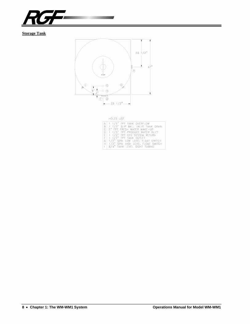
Storage Tank

Operations Manual for Model WM-WM1 Chapter 2: Installation 9
Chapter 2: Installation
Installation Requirements
The WM-WM1 System must be installed in strict compliance with these procedures in order for the warranty to be activated. The purchaser is responsible for bringing the required utilities (i.e. water, electricity and drainage) to the system and connecting them according to local codes. If the system must be modified by RGF or the distributor in order to meet the requirements of local codes, the purchaser will be required to pay the modification costs. When the purchaser has completed all of the above, a field representative will be furnished by the RGF Distributor. He will provide installation check-out, testing and training at no charge.
Please read the installation procedure completely and thoroughly before installing and operating the unit.
Installation Procedure
It is important to fully understand Chapter 1.0 to help to become familiar with all of the components and equipment names of your particular system for installation, start up, operating and maintenance procedures
NOTE:
Make sure to use Teflon tape or Teflon paste on all threaded connections and PVC glue (medium blue PVC cement) on all slip connections.

10 Chapter 2: Installation Operations Manual for Model WM-WM1
Equipment Placement Place all of the equipment skids and tanks on the concrete pad location as desired. Allow a minimum of 2' clearance between components for access ways.
Main Drain Return Line A. MAIN DRAIN RETURN LINE should be imbedded in the equipment
pad prior to system installation. If there is not one available, one should be plumbed to accommodate drain return lines from the components of the system. This return line should be readily accessible from the rear of each component such that all of the drain lines from each component can be plumbed into a common manifold and fed into the Main Drain Return Line (refer to the "Suggested Layout).
Main Electrical Connection A. MAIN ELECTRICAL JUNCTION for the particular system
components should be planned into the equipment pad prior to system installation. Most installations will require 220 VAC, 30 amps, 1 phase, 60 Hz with a neutral and a ground as a minimum.
Centrifugal Coalescing Clarifier (CCC Tank) Make the following connections to the Centrifugal Coalescing Clarifier.
A. Plumb a 1 1/2" PVC pipe line from the SUMP LIFT STATION to the
1 1/2" CCC TANK INLET. This line requires the use of a back flow
preventor and an isolation valve.
B. Plumb a 1 1/2" PVC pipe line from the 1 1/2" CCC TANK OUTLET
to gravity feed to a recycling system or sewer discharge. This line requires the use of a anti-siphon and a throttle/isolation valve.
C. Assemble the BAG FILTER underneath the cone tank. Attach the 1 1/2" BALL VALVE to the 1 1/2" FPT DRAIN CONNECTION.
Plumb the TANK DRAIN to the MAIN DRAIN RETURN LINE.
Hydrocarbon Accumulator Assemble the Hydrocarbon Accumulator and stand by the following procedure (Refer to the following figure for details).
A. Assemble the ACCUMULATOR STAND by forming a "+" with the
two 9" x 16" cross pieces with the flat sides up and placing the 16" square stand top on top of them. Use the 9 S.S. #6 x 5/8" Pan Phillips Screws and fasten the stand top to the cross pieces. Place and level it near the CCC Tank.
B. Place the HYDROCARBON ACCUMULATOR on the stand.
C. Plumb the 1 1/2" OIL SKIMMER OUTLET from the CCC Tank to
the HYDROCARBON ACCUMULATOR INLET.

Operations Manual for Model WM-WM1 Chapter 2: Installation 11
D. Attach the OIL ACCUMULATOR PIPE to the inlet connection on the inside of the tank being sure the INNER CHAMBER is positioned so the pipe will pass through the side of the inner chamber.
E. Attach the 11/2" OUTLET PIPE ASSEMBLY to the Oil Accumulator
Outlet. Plumb the Outlet Pipe Assembly from the "T" back to the main drain return line.
F. Attach the 11/2" SLIP BALL VALVE with the 11/2" Dia. x 3" L to the
11/2" threaded DRAIN CONNECTION on the side of the Accumulator.
Plumb the Drain Connection of the Accumulator back to the main drain return line.
Hydrocarbon Accumulator Assembly
Biosorb Series I
Biosorb Series I and Clarifier Position
A. Position the inlet of the Biosorb Series I Tank to face towards the CCC 400 tank and the Clarifier should be positioned next to the Transfer tank.
HYDROCARBONACCUMULATOR TANK
INNER CHAMBER
DRAIN BALL VALVE
ACCUMULATOR STAND
OUTLET PIPEASSEMBLY
DRAIN RETURNTO MAIN SUMP
OIL ACCUMULATORPIPE
ACCUMULATOR LID
INLET INTO ACCUMULATOR

12 Chapter 2: Installation Operations Manual for Model WM-WM1
Inlet Pipe Assembly Pipe Lubrication Application
Figure 2.1
A. Plumb a 2" line from the CCC 400 Outlet the Inlet of the Biosorb
Series I. Include in this line a 2” Throttle/Isolation ball valve. This valve is provided to throttle the feed flow rate to the Biosorb during operation. Lubricate the 2” pipe with a soap and water mixture to allow for easy installation as illustrated above.
B. Plumb a 3” outlet pipe from the Outlet of the Biosorb Series I Tank to the inlet on the Clarifier 3” tee fitting at top of tank.
Outlet Connection A. Plumb the Clarifier Outlet to the inlet of the transfer tank from either
side of the skimmer assembly. The unused side of the skimmer should be capped.
Additional Biosorb Series I Connections A. Position the Air Blower in a convenient position next to the Biosorb.
Plumb the Blower into the Air Inlet on the Biosorb Tank. Install the air filter to the suction side of the blower. The suction side can be located by observing direction arrows.
B. Plumb the Clarifier Sludge Suction line from the ¾” connection on the Clarifier Tank to the sludge lift return on the Biosorb Tank.
C. Connect the supplied 3/8” poly line on the Clarifier and connect it to the 3/8” compression ball valve located at the end of the Air Supply Manifold.
D. Plumb all of the 1 ½” drain lines to the Main Drain Return Line.
Operations Manual for Model WM-WM1 Chapter 2: Installation 13
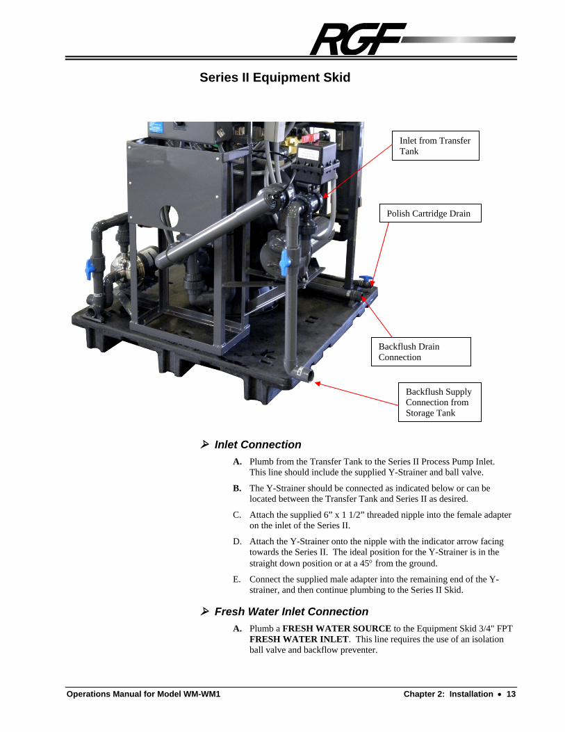
Series II Equipment Skid
Inlet Connection
A. Plumb from the Transfer Tank to the Series II Process Pump Inlet. This line should include the supplied Y-Strainer and ball valve.
B. The Y-Strainer should be connected as indicated below or can be located between the Transfer Tank and Series II as desired.
C. Attach the supplied 6” x 1 1/2” threaded nipple into the female adapter on the inlet of the Series II.
D. Attach the Y-Strainer onto the nipple with the indicator arrow facing towards the Series II. The ideal position for the Y-Strainer is in the straight down position or at a 45 from the ground.
E. Connect the supplied male adapter into the remaining end of the Y-strainer, and then continue plumbing to the Series II Skid.
Fresh Water Inlet Connection
A. Plumb a FRESH WATER SOURCE to the Equipment Skid 3/4" FPT FRESH WATER INLET. This line requires the use of an isolation ball valve and backflow preventer.
Backflush Supply Connection from Storage Tank
Backflush Drain Connection
Inlet from Transfer Tank
Polish Cartridge Drain

14 Chapter 2: Installation Operations Manual for Model WM-WM1
CFC System Inlet / Outlet Connection
A. Plumb from the CFC SYSTEM INLET to the SERIES III STORAGE TANK OUTLET. This line requires the use of an isolation ball valve.
B. Plumb from the ¾” CFC SYSTEM OUTLET fitting on the top of the UV/O3 Catalytic Chamber to the SERIES III STORAGE TANK CFC SYSTEM RETURN INLET.
C. Plumb the CFC BLEED BACK from the 1/4” fitting on top of the UV/O3 Catalytic Chamber using part of the supplied 1/4" poly hose and lead into the MAIN DRAIN RETURN LINE.
Drain Return / Bleed Line Connections
A. Plumb the 3/4" POLISHING FILTER DRAIN to the MAIN DRAIN RETURN LINE.
B. Plumb the POLISHING FILTER BLEED LINES (petcock valves on the sides and tops of the filters) to the MAIN DRAIN RETURN LINE.
E. Plumb the 1 1/2” MULTI-MEDIA FILTER DRAIN to the MAIN DRAIN RETURN LINE.
C. Plumb the Polishing Filters SOLIDS BLEED VALVES (bottom hose valves on housings) using part of the supplied 3/8" poly hose and lead back to the MAIN DRAIN RETURN.
NOTE:
The top hose valves are only needed for bleeding air from canister during startup.
CFC System Inlet
Outlet to Hose or Pressure Washer
UVO3 Venturi

Operations Manual for Model WM-WM1 Chapter 2: Installation 15
Electrical Connections
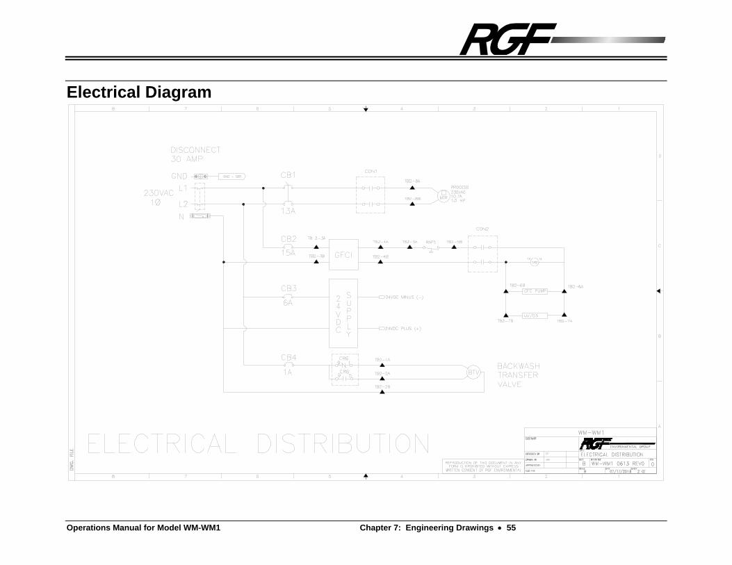
A. The 220 volt Electrical Connections to the SERIES II ELECTRICAL JUNCTION BOX should be connected by a certified electrician, according to local and national codes (refer to Section 8.3, Electrical Diagram).
IMPORTANT:
Do not turn on the power to the unit until instructed by this manual to do so. Damage to the system pumps will result otherwise.
Polish Filter Product Connection
A. Plumb the PRODUCT OUTLET to the SERIES III STORAGE TANK PRODUCT INLET (1 1/2" Product Inlet hole on top of Storage Tank).
NEUTRAL L1 L2 GROUND
24VDC PWR SUPPLY

16 Chapter 2: Installation Operations Manual for Model WM-WM1
Polish Filter Backwash Connection
A. Plumb the BACKFLUSH OUTLET to the MAIN DRAIN RETURN LINE.
Delivery System Inlet / Outlet Connection
A. Plumb the DELIVERY SYSTEM INLET to the STORAGE TANK DELIVERY OUTLET. This line requires the use of an isolation ball valve.
B. Plumb the DELIVERY SYSTEM OUTLET to the desired wash equipment.
Multi-Media Filter
A. Fill the Multi-Media Filter housing with the supplied media using the following procedure. Remove the Multi-Media Filter head assembly of the filter by unscrewing the lid from the top of the vessel using the supplied head wrench. Remove the head from the body assembly being careful not to lose the o-ring.
B. Ensure the standpipe is properly installed and in the vertical position.
C. Fill the media filter with water to just above the bottom laterals to prevent damage during media installation.
D. Make a funnel out of cardboard to help install the media. First install all of the rock media in the bottom of the housing. Ensure the standpipe remains centered during media installation. Level out the fist layer of media. Next, install all of the sand media into the housing, leveling upon completion. Then, install all of the anthracite carbon media, leveling upon completion.
E. Reinstall the filter head. Ensure the o-ring for the head is intact before re-installation.
Product Outlet

Operations Manual for Model WM-WM1 Chapter 2: Installation 17
Series III Storage Tank
Overflow / Drain Connection
A. Plumb from the STORAGE TANK OVERFLOW to the nearest overflow / storm water containment, sanitary sewer or secondary storage tank according to local and national code or plumb to the Main Drain Return Line.
NOTE:
Check with local authorities as to local codes for overflow water.
B. Plumb from the STORAGE TANK DRAIN, to the MAIN DRAIN RETURN LINE. This line requires the use of an isolation ball valve.
Fresh Water Inlet Connection
A. Plumb a FRESH WATER SOURCE to the 3/4" FRESH WATER MAKE UP INLET. This line requires the use of an isolation ball valve and backflow preventer.
Float Switch Connections
A. Attach all of the STORAGE TANK FLOAT SWITCHES according to Section 8.3 Electrical Diagram. These connections should be connected by a certified electrician according to local codes.


Operations Manual for Model WM-WM1 Chapter 3: System Startup and Operation 19
Chapter 3: System Startup and Operation
System Startup
Before you begin
The following startup procedures must be followed thoroughly in order to prevent damage to the system components.
Do not apply power to the system until directed to do so in the specific startup procedure!
Centrifugal Coalescing Clarifier (CCC Tank
Filling the System A. Close the drain valve at the bottom of the tank and
close the Hydrocarbon Accumulator drain. B. Fill the CCC Tank with water to its' normal operating
level (where it starts to gravity overflow). C. Turn on the sump pump and adjust the Oil Skimmer
so it will skim the surface of the water in the tank when the pump is in operation.
D. Check the optional Macro Aerators to see that they are functioning properly (i.e. bubbling evenly inside of tank).
!

20 Chapter 3: System Startup and Operation Operations Manual for Model WM-WM1
Biosorb Series I
Filling the System
A. Close all DRAIN VALVES (e.g. valves PF-1 and PD-2).
B. Close all of the ISOLATION VALVES between the components of the system.
C. Fill the tanks of the system evenly and at the same time in order to prevent damage to the compartment baffles of the tank. Continue to fill the system until the water in the tank starts to flow out of the Clarifier Skimmer.
Series III Storage Tank, Misc. Tanks and Pits A. Close the Storage Tank DRAIN VALVE and ISOLATION
VALVES.
NOTE:
Do Not Open the Isolation Valves until directed to do so.
B. Turn on the Fresh Water Supply to the Storage Tank. Fill the Storage Tank approximately 3/4 full (400 gallon mark) with fresh water with a garden hose.
C. Ensure all of the FLOAT SWITCHES inside of the Storage Tank are free to swing.
D. Fill the remaining tanks and pits of the system and wash pad to the filled position.
Series II Equipment Skid
Filling the System
A. Close all DRAIN VALVES (e.g. valves PF-1 and PD-2).
E. Recheck all unions to ensure they are not missing o-rings and are all hand tightened.
F. Ensure all filters are installed and the lids are hand tightened.
G. Open all of the purge valves on top of the filter housings (PF-1, PF-2, and PF-3).
H. Open the fresh water valves for the system (e.g., FW-1, FW-2 and FW-3). Allow the system to fill until water starts streaming from the purge valves, and then return the fresh water valves to close and then close all of the purge valves (PF-1, PF-2, PF-3, and PF-4).
I. Open all of the ISOLATION VALVES between the components of the system.
J. Prime the Process Pump by removing the square priming plug from the Process Pump housing until water starts streaming from the priming hole, then replace the plug. If the process tank is located below ground the pump will need to be primed by un-doing the top union of the pump and filling the casing with water.
Operations Manual for Model WM-WM1 Chapter 3: System Startup and Operation 21
F. Prime the CFC System Pump by removing the gauge fitting on the top of the CFC Pump piping assembly. Water should start emitting from the gauge fitting. Continue until a steady stream emits, then replace the gauge fitting.
NOTE:
Proper priming of this pump is of extreme importance. Failure to ensure proper priming will inhibit proper operation of the pump and destroy it.
H. Prime the Delivery Pump (Optional) by removing the square priming plug from the Delivery Pump housing until water starts streaming from the priming hole, then replace the plug.
Polishing Filter System
A. Prepare the Polishing Filter System valve positions for normal operation by opening PF-3 and PP-1 and closing PB-1 and PD-2. For AUTOMATIC SYSTEMS these valves are electric solenoid valves and will open and close automatically
CFC / CO3P System
A. Prepare the CFC System for normal operating by opening CFC-1.
Start-Up A. Open all of the isolation ball valves between the components of the
system.
B. POWER CAN NOW BE APPLIED TO THE SYSTEM COMPONENTS.
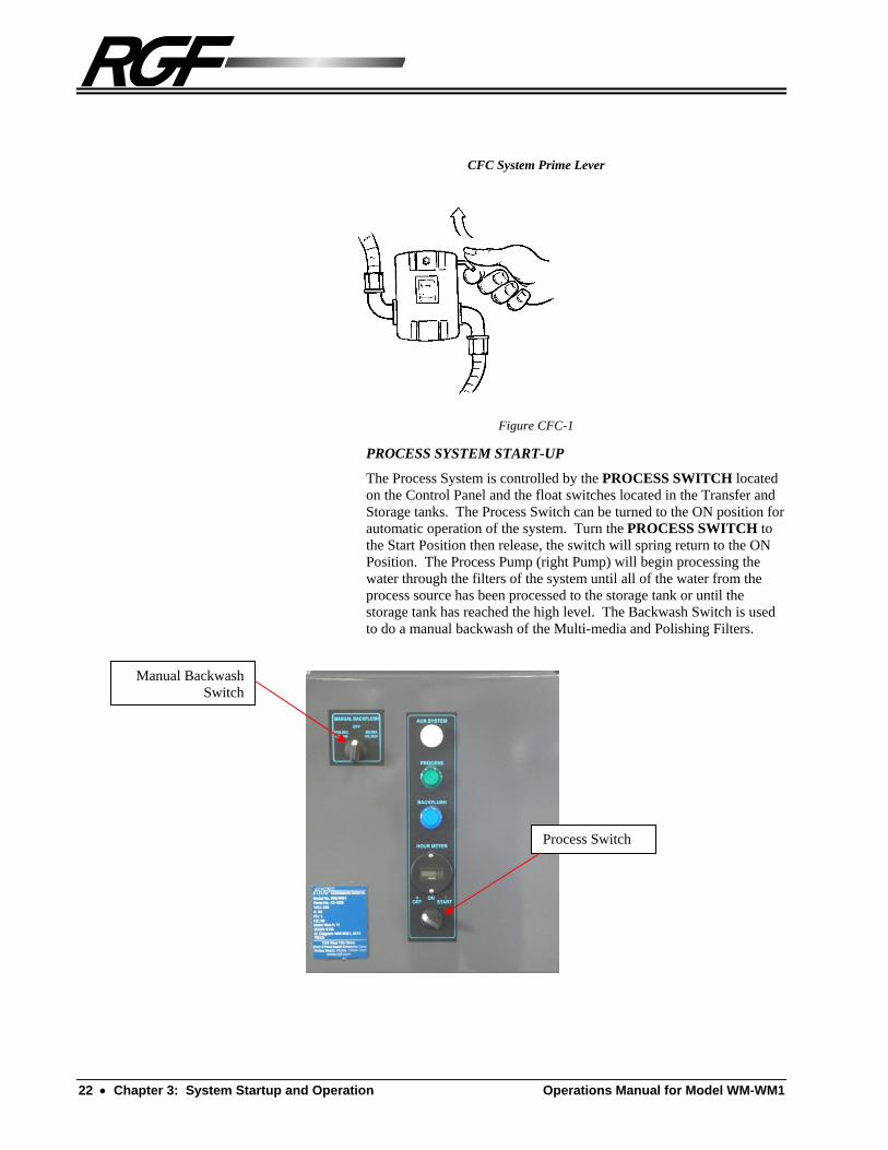
CFC SYSTEM START-UP
Start the CFC system by holding the CFC SYSTEM PRIME LEVER up (refer to Figure CFC-1) until the CFC pressure reaches approx. 11 psi, then release. The lever should remain in the up position. If it does not, then the CFC System is not properly primed, check the system valves to ensure they are properly opened and re-bleed the CFC pump. Once the CFC System is properly started, the Aux. System light and UV/O3 Catalytic Chamber indicator (blue light on the side of the chamber) should be illuminate indicating that power has been applied to the CFC System. Also, the CFC Pump will run continuously, and the Chemical Injector Pump will pump periodically. If in the event the CFC system loses prime, the lever will shut down to prevent equipment damage.
22 Chapter 3: System Startup and Operation Operations Manual for Model WM-WM1
CFC System Prime Lever
Figure CFC-1
PROCESS SYSTEM START-UP
The Process System is controlled by the PROCESS SWITCH located on the Control Panel and the float switches located in the Transfer and Storage tanks. The Process Switch can be turned to the ON position for automatic operation of the system. Turn the PROCESS SWITCH to the Start Position then release, the switch will spring return to the ON Position. The Process Pump (right Pump) will begin processing the water through the filters of the system until all of the water from the process source has been processed to the storage tank or until the storage tank has reached the high level. The Backwash Switch is used to do a manual backwash of the Multi-media and Polishing Filters.
Manual Backwash Switch
Process Switch

Operations Manual for Model WM-WM1 Chapter 3: System Startup and Operation 23
System Operation
Centrifugal Coalescing Clarifier (CCC Tank The system operates on a gravity flow / gravity separation process. Water from the sump pump enters the CCC Tank from the Inlet Manifold, invoking a whirlpool. This centrifugal action helps to separate the oils and solids from the waste stream causing oils to float to the surface and solids to fall to the bottom. The oils are removed by the oil skimmer and deposited in the Hydrocarbon Accumulator, where the remaining water and oils are further separated. The solids settle to the bottom of the cone tank. They are removed during periodic maintenance by dumping the accumulated solids into the bag filter, for easy transportation and disposal. The clarified water is then gravity fed out of the system to a recycling system or to sewer.
Biosorb Series I
Process Description:
Biosorb Series I Tank:
The main job of treating and breaking down the pollutant and biological material in the reclaimed washwater takes place in the aeration chambers or “BIOZONES” of the Biosorb Series I Tank. A large volume of air is supplied to the aeration chambers from the supplied regenerative air blower. This air is introduced at the bottom of the chambers through a series of simple diffusers to create a fully aerated liquid. A complex system of microorganisms, supported on plastic media, uses the aerated conditions to break down the biodegradable material present in the wash water. This form of treatment is called secondary treatment and it produces a much cleaner effluent than the traditional septic tank style of primary treatment.
Clarification Stage – Biosorb Series I Clarifier:
Any solids or flocs produced in the Biosorb Series I “Bio-Zones” will settle out in this compartment under quiescent conditions. The sludge that accumulates at the bottom of this chamber is automatically returned to the Biosorb Series I tank for re-activation. The clarified effluent then passes through to the #2 Anaerobic Tank.
Series II Equipment Skid
Process System
Water enters the Process System from the #2 Anaerobic Tank or optional process tank by the suction of the Process Pump and is passed through the Multi-Media Filter and then through the three Polishing Filters by the process pump where it is delivered to the Storage Tank.
For Automatic Systems, the Multi-Media Filter is automatically controlled and backwashed by the Multi-Media Filter Controller and the Polishing Filters are automatically backflushed by the PB-1, PF-3, PP-1 and PD-2 valves which are electric solenoid valves controlled by the BackwashTimer located in the main electrical junction box.

24 Chapter 3: System Startup and Operation Operations Manual for Model WM-WM1
Controlling Flow
Flow through the Process System is controlled by the Multi-Media Filter Valve and the Polishing Filter Valves.
CFC System (Continuous Flow Control)
Water is continuously fed through the CFC system from the Storage Tank by the
suction of the CFC System Pump and is supplied to the CO3P Process. Flow through
the CO3P Process passes recycled water through the Ozone and Chemical Venturi and the O3/UV Catalytic Chamber, and is returned to the Storage Tank.
NOTE:
In order for the catalytic oxidation process (CO3P) to operate correctly, it is necessary to keep the hydrogen peroxide level in the Storage Tank above 10 ppm. For the first several weeks of operation of the system, monitor the level very closely. If the residual hydrogen peroxide level falls below the 10 ppm range, it will be necessary to increase the injection rate accordingly. The chemical output of the pump ranges from 0.96 GPD at the minimum setting to 16.2 GPD at the maximum setting.
Controlling Flow
Valve CFC-1 should be fully opened for normal operating conditions.
IMPORTANT:
Valve CFC-1 must never be shut completely off. The UV/O3 Catalyzation Chamber requires continuous flow or the chamber will overheat and malfunction.
WATER SUPPLY (Optional)
The water supply to the washing equipment is supplied by the optional Delivery Pump. This pump maintains pressurized feed to the washing equipment. If in-sufficient pressure is achieved, the delivery pump pressure can be increased by changing the pressure switch to a maximum of 45 psi.
Series III Storage Tank
Operation
Water enters the Tank from either the Series II Skid or fresh water make-up. The
water inside the tank is continuously pumped by the CFC System, through the CO3P Process, and returned. When wash water supply is needed, wash water flow is pumped by the optional delivery pump to the point of use. Float switches inside of the tank control the operation of the system.
This system has a high level (pump up) float switch. In addition, if the tank water level reaches a level below 18”, the fresh water make-up valve will allow fresh water to enter the tank.

Operations Manual for Model WM-WM1 Chapter 3: System Startup and Operation 25
Operational Notes
UV/O3 CATALYTIC CHAMBER
1) DO NOT look at the UV light in the chamber. PERMANENT DAMAGE OR BURNS TO EYES OR SKIN MAY RESULT.
2) DO NOT run the UV Chamber without water flow through the Chamber, The UV bulb needs water flow to keep it cool. DAMAGE TO THE BULB WILL RESULT.
2) DO NOT open or attempt to repair the chamber. If problems occur, call your serviceman or distributor for further instruction.
3) DO NOT BREATHE OR INHALE THE OZONE GAS. PROLONGED BREATHING OF NOTICEABLE AMOUNTS OF OZONE may result in: respiratory irritation to nasal passages, throat, bronchial and pulmonary membranes; headache, nausea, burning, watery irritated eyes. In some instances (such as enclosed spaces and tanks), significant concentrations of ozone may collect. Adequately vent all tanks and enclosed spaces before entering for maintenance or repair until the level of ozone has depleted down to acceptable levels (<0.1 ppm). If an ozone odor is still noticeable, continue ventilating until the odor is non-detectable. Ozone odor is similar to the smell near copy machines when making copies or Mig and Tig welders in operation and is the "fresh air " odor one sometimes notices after a thunderstorm.
GENERAL NOTE:
At a level of 1 ppm, ozone becomes intolerable to humans. A humans reaction to this level is the same as the reaction to a strong bleach or ammonia odor. Usually, the nose will indicate discomfort.
POLISHING FILTER
1) Before servicing be sure to RELIEVE THE PRESSURE on the Polishing Filter(s) by using the drain valve and bleed valve or PERSONAL INJURY COULD RESULT!!!.
2) RGF Filters have been lab tested and time tested - COPY FILTERS HAVE BEEN KNOWN TO BREAK UP OR DISSOLVE, THEREBY PLUGGING OTHER PARTS OF THE UNIT CAUSING EXCESSIVE PRESSURE AND EQUIPMENT DAMAGE!!!
!
!

26 Chapter 3: System Startup and Operation Operations Manual for Model WM-WM1
CFC SYSTEM PUMP:
1) Proper priming of the CFC System Pump is essential to the operation of the pump. Improper priming of the pump will cause poor performance and eventual pump failure.
2) DO NOT OPERATE the CFC System Pump if the Storage Tank is emptied or DAMAGE TO THE PUMP WILL RESULT.
PROCESS PUMP:
1) TO PREVENT DAMAGE TO THE PROCESS PUMP, DO NOT OPERATE without sufficient prime and net positive suction head (NPSH).
2) DO NOT OPERATE THE PUMP while the system valves are closed.
DELIVERY PUMP (OPTIONAL):
1) TO PREVENT DAMAGE TO THE DELIVERY PUMP, DO NOT OPERATE without sufficient prime and net positive suction head (NPSH).
2) DO NOT OPERATE THE PUMP while the system valves are closed.
!
!
!

Operations Manual for Model WM-WM1 Chapter 4: Preventative Maintenance Schedule 27
Chapter 4: Preventative Maintenance Schedule
Overview
The following section is developed to keep the WM-WM1 System in top working order. It is NECESSARY to follow the maintenance procedures below precisely as stated. The lack of maintenance, in the long run, will reduce productivity and can be both costly and time consuming. It is recommended that this format be copied and incorporated as a regular work routine.
Turn off all power, and release pressure before servicing the system. All gauges must read zero!
Required Tools and Supplies Hammer Adjustable End
Wrench 5 H.P. Shop VAC
For Extracting Old Media
Garden Hose For Back Flushing
Tube Brush For UV/O3 Chamber Cleaning
pH Test Strips
Garden Hose Nozzle
#1 Flat Head Screw Driver For Venturi Adjustment If Needed
Garbage Bag For Proper Filter Disposal
Rubber Boots And Gloves
Proper Safety Equipment
Square Head Shovel For Digging Out Trench Valley
!

28 Chapter 4: Preventative Maintenance Schedule Operations Manual for Model WM-WM1
Daily Maintenance
Centrifugal Coalescing Clarifier (CCC Tank) A. Open the Drain Valve on the bottom of the CCC
Tank and the Bag Filter Tank and allow to drain for several minutes to flush out sediments. Return valve to close. Remove the Filter Bag and properly dispose of the collected debris and sediment.
B. Drain the water out of the bottom of the Hydrocarbon Accumulator using the Drain Valve. Let run until oil starts coming out of the drain. Return valve to close. If there is a large amount of oil in the accumulator, then it will need to be drained off and disposed of properly. Drain the oil off by connecting a hose to the tank drain and leading it to a 5 gallon can or drum.
BIOSORB System Maintenance
Weekly Maintenance A. Remove floating solids from the surface of the Clarifier.
B. Check that the blower, sludge lift, and discharge pump are operating properly.
Sludge Maintenance Procedure
Large solids in the wastewater will settle out in both the holding tanks and the primary chamber. These solids collect at the base of these compartments and form sludge. This sludge degrades biologically over time but accumulates gradually and needs to be removed periodically.
It is important that the correct procedure for the de-sludging of the “BIOSORB” is carried out. The following steps need to be performed.
IMPORTANT: Please post Health and Safety information and issue a copy to personnel involved in the de-sludging of the system before commencing.
A. Ensure that all power to the unit is switched off.
B. Open the drain valves of the Biosorb Series I Tank for 30 seconds to remove settled sludges from the bottom of the tank.
C. Liquid should be removed until approximately six inches (150 mm) is removed from each chamber.
D. After de-sludging, the chambers and holding tanks should be refilled by adding clear water.
E. After refilling, all electrical power to the units should be restored.

Operations Manual for Model WM-WM1 Chapter 4: Preventative Maintenance Schedule 29
Series II Equipment Skid
Daily System Check
Daily, with the system running, log the pressure gauge readings. Check the status of the indicator lights, hour meter, and chemical injection pump. Check the water level in the Storage Tank. Keep an accurate record of all of the readings and indicators to determine when certain components of the equipment skid will need maintenance
.
NOTE:
Use the following as general rules:
Multi-Media Filter
If the pressure difference across the Multi-Media Filter is greater than 20 psi, the filter will need to be backwashed according to the Multi-Media Filter Procedure.
Polish Filter Gauges
If the pressure difference for the Polishing Filters is 10 psi or more, the filters need to be back flushed or manually cleaned.
CFC Pump Discharge Gauge
This gauge indicates the pressure in the CFC System. The system should operate at approximately 11 psi when there is no recycled water usage and 4-10 psi when there is recycled water usage.
Polishing Filters
Daily Maintenance
Daily, or if the inlet and outlet pressure difference on the Polishing Filters is greater than 10 psi, the filters need to be back flushed by the following procedure.
AUTO BACK FLUSH NOTE:
For Automatic Systems, if it is found that the Polishing Filters are not being back flushed properly, then the Auto Back Flush Sequence will need to be adjusted accordingly.
UV/O3 Catalytic Chambers
DAILY MAINTENANCE
A. Ensure the UV/O3 Catalytic Chamber indicator light on the side of the chambers (at the top) is illuminated.

30 Chapter 4: Preventative Maintenance Schedule Operations Manual for Model WM-WM1
Weekly Maintenance
Trenches, Sumps, Pits, and Clarifiers
Weekly Maintenance
Weekly, or as required, the trenches, sumps, pits and clarifiers of the pad need to be checked for sediment level. The trenches' sediment level should not be more than half of the depth of the trench. Dig out the trench using a shovel, and dispose of the waste accordingly. The sumps and pits should be dug out if there is at least 1/4 of the depth full of sediment. The clarifiers should be removed and dug out on a weekly basis, or as required, regardless of the amount of sediment.
IMPORTANT:
Dig out the trenches, sumps, pits and clarifiers as regularly as possible. Keeping them cleared of sediment build up will result in better water quality throughout the entire system.
Y-Strainer
Weekly Maintenance
A. Turn the Process Control Switch to OFF.
B. Close the isolation valve to the Series I and valve PF-4 on the Series II.
C. Unscrew bottom of the Y-strainer, taking care not to lose the o-ring, and completely clean screen basket.
D. Reassemble Y-strainer bottom with o-ring in place.
E. Open isolation valve to the Series I and valve PF-4 on the Series II and reapply power.
F. Check for leaks.
Multi-Media Filter
Weekly Maintenance
Weekly, or if the pressure difference across the Multi-Media Filter is greater than 20 psi, then the filter will need to be manually backwashed by the following procedure.
AUTOMATIC MULTI-MEDIA FILTERS
Manually Backwashing the Multi-Media Filter
A. The Process Control Switch must remain in the ON position for this operation.
B. Ensure there is sufficient water in the Process Tank to perform a sufficient backwash.
C. Initiate a manual backwash cycle by placing the Manual Backwash switch in the Media Filter position. The following control sequence will occur:
The Process Pump will turn off.

Operations Manual for Model WM-WM1 Chapter 4: Preventative Maintenance Schedule 31
The backwash valve will move to the backwash position.
The Process Pump will restart, moving the water through the filter in the backwash direction then to the waste line. Backwashing will continue for 3 minutes.
The process Pump will turn off.
The Backwash valve will move back to the filter position.
The sandbed will be allowed to settle for 1 minute.
The Process Pump will turn back on and normal filtering will proceed.
E. Return the Manual Backwash Switch to the OFF position. The pump will continue to process water.
Polishing Filters
Weekly Maintenance
Weekly the Polishing Filters need to be removed and manually cleaned by the following procedure:
A. Place the Process Switch in the OFF position
B. Open the Filter Housing drain valve to release pressure and drain the filter housing.
C. Remove the Filter Housing Lid.
D. Remove Polish Filter Cartridge and clean with fresh water. Do not use pressure washer to clean filter cartridge.
E. Re-install Filter Cartridge into the filter housing.
F. Verify Housing Lid o-ring is in place.
G. Install Filter Housing Lid.
H. Close the Filter Housing drain valve.
I. Place the Process Switch in the ON position
Storage Tanks
Weekly Maintenance
A. Open the drain valve to the Storage Tank and allow to drain for 1 minute to remove any accumulated solids from the bottom of the tank.
B. Check inside the tank to ensure the float switches are free to swing. Remove any accumulated debris or scum from the surface of the tank water.

32 Chapter 4: Preventative Maintenance Schedule Operations Manual for Model WM-WM1
Monthly Maintenance
UV/O3 Catalytic Chambers
Monthly Maintenance
Once a month, or as required, the UV/O3 Catalytic Chamber needs to be cleaned by the following procedure:
Shut off all power to the system before attempting to service or repair the UV/O3 Catalytic Chamber. The chamber operates under high voltage, which can cause severe shock if ends are removed while power is applied.
A. Turn the main power to the system OFF.
B. Close the Isolation Ball Valves (CFC-1) to the CFC System.
C. Disconnect the union at the top of the UV/O3 chamber. It may be necessary to disconnect the bottom union to thoroughly clean the lower portion of the tube.
NOTE:
Use caution in handling the UV/O3 Catalytic Chamber. The UV bulb is extremely fragile and will break if the chamber is mishandled.
D. Insert an appropriate sized bottle brush and scrub the interior of the quartz glass tube. If a heavy build up of scale is present, prepare a solution of Citric Acid and scrub the tube until clean.
E. Reconnect the inlet and outlet and open isolation ball valve (CFC-1).
F. Turn the main power to the system back ON.
!

Operations Manual for Model WM-WM1 Chapter 4: Preventative Maintenance Schedule 33
As Required Maintenance
Multi-Media Filter
As Required Maintenance
If the Multi-Media Filter has a high-pressure differential after continued backwashing or if the Polishing Filters are continually fouled, then the media will have to be changed by the following procedure.
Changing the Filter Media
A. Turn the Process Control Switch to OFF.
B. Ensure all pressure is relieved from the system (all gauges should read zero). Loosen the unions of the Multi-Media Filter and remove the head. Remove the drain Plug from the bottom of the Multi-Media Filter.
C. Once all of the water has drained, use a 5 horsepower wet / dry shop vacuum to remove the old media. Once all the media has been removed, thoroughly clean and flush out the filter housing.
D. Replace the media with RGF Filter part # FL-078 and replace media to filter housing according to the Multi-Media Filter installation instructions.
E. Re-assemble the filter housing and return to normal operation.
Programmable Auto BackFlush Change the Programmable Auto-Backflush sequence if the filters need to be back flushed more frequently. The Auto Back Flush Timer is factory pre-set to 24 hours between back flushes (T OFF dial) and two minutes of back flush (T On dial).
A. Turn the main power to the system OFF.
B. Open the Electrical Junction Box and remove the ODR relay
C. The dials on the face of the relay control the amount of time between back flushes (T OFF dial) and the amount of time the back flush is performed (T ON dial).
To change the amount of time between back flushes, turn the T OFF dial to the desired amount of time (scale is in hours). To change the amount of time the back flush is performed, turn the T ON dial to the desired amount of time (scale is in minutes.
If more than 10 minutes of back flushing is preferred, it will be necessary to change the time scales of the relay. On the side of the relay are the Repeat Cycle switch settings which control the scale of the time OFF and time ON functions of the relay. They are factory set so the relay time OFF dial is in hours and the time ON dial is in minutes. To change them, refer to Chapter 10; Auto Back Flush Timer.
34 Chapter 4: Preventative Maintenance Schedule Operations Manual for Model WM-WM1
NOTE:
If the power to the system is turned OFF, the timer restarts it's cycle from zero. The timer relay does not retain it's time cycle during power OFF.
Winterizing the System In areas of the country where the system will be shut down for the winter or there is a possibility of local freezing, the system will need to be drained down to prevent damage to the internal components and piping of the system. The water from the system should be hauled off or evaporated. All main sumps to the system should be turned off, pumps removed and covered to prevent damage to the sump basins. All power to the system should be shut off completely. The components of the system should be drained completely (e.g. pumps, filter housings, UV/O3 Chamber)
Operations Manual for Model WM-WM1 Chapter 5: General Theory 35
Chapter 5: General Theory
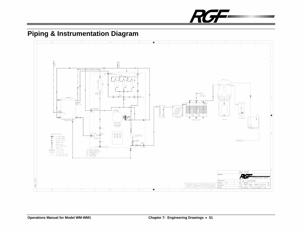
Overview The Piping and Instrumentation Diagram in the Engineering Diagram Section outlines the path that the waste stream follows as it is recycled. The General Theory section explains each process of the recycling process. A comprehensive understanding of theory of the WM-WM1 System should be achieved to assist in the proper installation, operation and maintenance of the system.
Biosorb Series I System
Biosorb Series I The Biosorb was designed to accommodate a variety of wastewater applications with high B.O.D. and C.O.D. levels. Our goal in treating wastewater high in organic contaminants is to convert the carbon into microorganisms that we can remove from the water by settling. The Biosorb provides an aerobic environment that encourages the growth of organisms - organisms that use organic material for both their carbon and energy source. The clarifier provides a method for settling out the bugs and re-activating them within the system.
Series II Equipment Skid
Process System The process water enters the Process System of the Series II equipment Skid by the suction of the Process Pump. The water is filtered through the Multi-Media Filter removing large particulate from the waste stream then passed through the Polishing Filters for final polishing of the water. The Multi-Media and Polishing Filters are periodically backwashed to remove accumulated particulate.
The process water enters the Process System of the Series II equipment Skid by the suction of the Process Pump. The water is filtered through the two primary Polishing Filters of the system down to the 10 micron range before passing it on to the MS3 Membrane System. The third filter is the Back-Up Supply Filter, which is only activated by a low level signal in the Series III Storage Tank, which opens the SB-7 solenoid valve, then supplies this water to the Storage Tank. The Polishing Filters are equipped with air and solids purge valves and have a system for back flushing the filters. From the Process System, the water then enters into the MS3 Membrane System.

36 Chapter 5: General Theory Operations Manual for Model WM-WM1
Supply Header The supply header comprises a manifold of piping and valves, which allows the operator to select the water source to be supplied to the wash equipment. The operator may select either wash or rinse water to be delivered to the wash equipment. Rinse water typically is municipally supplied 40-60 psig "tap" water. Recycled wash water will come from one of the following sources depending on system parameters:
1) The CFC system is the primary source of recycled wash water.
2) When the Storage Tank is below the Low Level float set point, the wash water is supplied by the effluent of the #3 Back-Up Polish Filter.
Continuous Flow Control System (CFC System) The CFC system consists of the CFC Pump, the UV/O3 Chamber, venturi injection, and hydrogen peroxide injection. The purpose of the system is to continuously provide recycled water at moderate supply header pressure and to continuously circulate water through the Catalytic Oxidation Process (CO3P). Although the terms CFC and CO3P are related and the systems utilize the same components. CFC refers to the mechanism for the hydraulic delivery system, and CO3P refers to the chemical and photochemical process for water treatment.
CFC Pump The CFC Pump is a 1/6 Hp. centrifugal circulation pump that pumps the processed
water from the storage tank to the Supply Header and through the CO3P system.
Catalytic Oxidation Process (CO3P System) The Catalytic Oxidation Process is designed to reduce the Biologic Oxygen Demand (B.O.D.) and Chemical Oxygen Demand (C.O.D) of the recycled water. This is accomplished through the contact with hydrogen peroxide, ozone and ultraviolet light. The tri-reaction is completed when the ultraviolet light (catalyst and oxidizer) in the chamber excites the ozone (oxidizer) and hydrogen peroxide (oxidizer) to cause them to react faster in the aqueous solution (refer to Figure TRI-1). Ultraviolet light is also a remarkable sterilizer of living organics such as bacteria and algae. In turn, the three work together in breaking down organics to clarify the water before it is reused. This is all accomplished by the CFC system, which transfers the water from the tank passing it by the hydrogen peroxide injection and ozone injection and through the UV/O3 Catalytic Chamber and returning it back to the tank.

Operations Manual for Model WM-WM1 Chapter 5: General Theory 37
RGF Catalytic Oxidation Process
Figure TRI-1
UV/O3 Catalytic Chamber A cylindrical vessel used to produce Ozone (O3) which is venturi injected in the
CFC system, to prevent bacteria or algae growth. The chamber also produces ultraviolet light, which is a sterilizer used to UV destruct organics and excite ozone
and hydrogen peroxide in the Catalytic Oxidation Process (CO3P) as the water passes through the chamber (refer to figure UV/O3-1).
UV/O3 Catalytic Chamber
Figure UV/O3-1
Delivery Pump The Delivery pump is utilized to deliver the recycled water to the washing equipment. This pump supplies water at a rate of 45 gallons per minute at 20 - 40 psi. The pump contains a pressure switch and pressure tank.
H2O2 O3OZONE
UVULTRAVIOLET LIGHT
HYDROGENPEROXIDE
UV
LIG
HT
EX
CIT
ES
HY
DR
OG
EN
PE
RO
XID
E
UV
LIGH
TE
XC
ITES
OZO
NE
RGFCATALYTICOXIDATIONPROCESS
HYDROGEN PEROXIDE INCREASESOZONE SOLUBILITY

38 Chapter 6: Controlling Water Quality Operations Manual for Model WM-WM1
Chapter 6: Controlling Water Quality
Overview
Controlling the waste water quality on the WASHMASTER System is a very important process that can greatly enhance the quality of your recycled water. By controlling the pH level, Total Alkalinity, the amount of oxidizers and soaps that are used, you will be able to improve the quality of water in your system. There are many factors which control the water quality. These factors are listed below in order of their appearance in the following section:
pH / Alkalinity
pH
Total Alkalinity
Oxidizers
Hydrogen Peroxide
Ozone
Ultraviolet Light
Cleaning Agents
Enviro-Control
Water Conditioner 1 (WC-1)
Solids
Total Dissolved Solids (T.D.S.)
Total Suspended Solids (T.S.S.)
Operations Manual for Model WM-WM1 Chapter 6: Controlling Water Quality 39
pH / Alkalinity
pH pH (potential hydrogen) is a relative measure to indicate how acidic or alkaline a substance is. Thus, it denotes the degree or strength of alkaline or acidity. Some acids or alkaline substances are stronger than others and, in order to compare them, the pH scale has been devised. The pH numerical index ranges from 1.0 (extremely acidic) to 14.0 (extremely alkaline). The midpoint of 7.0 indicates that the solution is neutral. That is, it is neither acidic nor alkaline. Pure distilled water is a neutral solution. Note: High pH’s tend to emulsify oils and reduce the efficiency of the unit. The use of high pH cleaners should be minimized.
The pH scale is a logarithmic scale and even though the difference from 0 to 14.0 doesn't seem very great, every unit on the pH scale is a difference of 10 times, and every two units is a difference of 100. For example, if you have an alkaline cleaning solution of 10.0 and increase it to 11.0, you are making that solution 10 times more alkaline. If you go up two degrees to a pH of 12.0, the solution becomes 100 times more alkaline, and so on.
Controlling pH:
To Raise pH:
One chemical usually added to raise the pH level is Sodium Carbonate. How much to add is basically a trial and error operation, but a general rule of thumb that is good to follow is to add 1/4 pounds of Soda Ash for every 1,000 gallons of water within the system. After adding the Soda Ash, wait for about an hour before re-checking the pH level. Take whatever further action is indicated by the test.
To Lower pH:
The chemical normally added to lower the pH level is called Muriatic Acid, which is actually a dilute form of the more hazardous hydrochloric acid and comes in liquid form. Another acid product is the so called Dry Acid or Sodium Sulfate, which comes in a granular form. Acid of any type should always be added directly to the water, NEVER the water to the acid! The amount of acid required is determined by performing an acid demand test with the water test kit.
Total Alkalinity Total Alkalinity is the measure of the total amount of alkaline chemicals in the water and not the same as pH. pH measures the strength of an alkaline (or acid), while alkalinity measures the amount of alkalis present. While pH and Total Alkalinity are not the same thing, Total Alkalinity can have an effect on how fast or easily changes in pH can be accomplished.

40 Chapter 6: Controlling Water Quality Operations Manual for Model WM-WM1
Controlling Alkalinity
For our purposes, the Total Alkalinity should be kept at about 150 ppm. In general, alkalinity has not been a problem for recycling, providing you are using a neutral soap. If you have a drum of water and introduce a scoop of alkaline clearer, you may change the pH and get a reading of 12. That does not mean that if you add a second scoop of cleaner, you will get a different reading - in fact, it will probably be identical. What will change is the Total Alkalinity.
Oxidizers
Ozone Ozone is another oxidizer that exhibits outstanding purifying characteristics. Ozone is different than hydrogen peroxide in that it is not in a liquid form. Ozone is produced by a unique process developed by RGF in which a special chamber called the TurboHydrozone uses air as it's agent to produce the ozone. A simple look at the blue indicator light on the chamber assures ozone is being produced. The ozonated air is then bubbled inside of the storage tank or is vacuum dragged into the
CO3P System by the Ozone Venturi, which agitates the water thus oxidizing it, which reduces B.O.D.'s and C.O.D.'s, removes odors and improves water clarity.
UltraViolet Light UltraViolet (UV) light is the third oxidizer used by RGF to complete the catalytic
oxidation process (CO3P). UV light is a sterilizer, which kills organics by emitting ultraviolet light inside of the UV Catalytic Chamber. This ultraviolet energy is also used to excite the hydrogen peroxide and the ozone that is already in the water to enhance their individual oxidation potentials.
Cleaning Agents In discharge systems the use of soaps or chemical additives is not recommended. If one must use detergents or additives they should be neutral pH, quick splitting variety and used sparingly. Cleaning Agents are added to open-looped recycling water systems to help remove the oils and road film off of the equipment being cleaned. Cleaning agents contain surfactants, which help to relieve the surface tension of the water, enabling the oils and particles to detach more readily from the equipment being cleaned. Some cleaning agents, however, may cause the oils to emulsify, which will not allow for easy removal, which in turn may end up back on the equipment. In order to prevent this, the cleaning agents in consideration for use with the system should be formulated with low to moderate foaming and limited oil emulsifying properties while remaining a neutral pH cleaner. RGF recommends the following two cleaning agents to be used with your system.
Enviro-Control RGF has developed a specially formulated soap for closed-looped recycling systems called Enviro-Control to use with your system. This soap is a water white blend of biodegradable surfactants containing all of the qualities listed above, plus it helps

Operations Manual for Model WM-WM1 Chapter 6: Controlling Water Quality 41
prevent bacteria and algae growth, inhibit corrosion. It has no dyes, perfumes or thickeners added, and it helps to flocculate oil accumulation.
Enviro-Control can be purchased in a super concentrated form through your distributor or RGF at 1-561-848-1826 or FAX 1-561-848-9454.
Water Conditioner-1 (WC-1) Water conditioners are a good addition to a recycling system because they help to maintain good water quality and help in releasing suspended solids. RGF has available a water conditioner that can do all of this and more, the Water Conditioner 1 (WC-1). This water conditioner has many water quality improving abilities. It aids in the flocculation of suspended solids, reduces B.O.D. and C.O.D. loading, and helps to soften the water. WC-1 also inhibits corrosion on your system, providing more years of service and will help to lower the total suspended solids count, which will improve the color and clarity of your recycled water. Since WC-1 can provide all of these benefits, it should be made a regular part of the chemical additions to your system.
Dissolved and Suspended Solids
Total Dissolved Solids (TDS) T.D.S. represents the total conductive material actually dissolved in the water (refer to Section 11.0 Addendums / Training Bulletin - TB 001). It is the same as salt or sugar dissolved in water and should not be confused with suspended solids or turbidity. Total dissolved solids can include both organic and inorganic materials. Inorganic materials can be soluble in many cases and add to T.D.S.. Any chemical addition to the water will increase T.D.S. (except hydrogen peroxide). Water treatment chemicals often solve one problem but create another problem. While an addition of a floccing agent may remove suspended solids and turbidity, it may drastically increase T.D.S.
Eventually, a solution with increasing T.D.S. will reach a level where it is considered to be saturated (i.e. it has reached its solubility constant). Saturation is when the addition of a soluble or dissolved solid reaches the maximum ability of the water to hold it in solution at a given temperature. When the T.D.S. level exceeds this level, the material comes out of solution and either settles or forms crystals, which is how rock candy is made.
T.D.S. is measured by a special conductivity meter, which works on the principle that "pure" water has no conductivity of electrical current. The addition of material such as T.D.S. increases the electrical conductivity; therefore, the higher the reading, the higher the T.D.S. level. Readings are in microsiemens - a unit of low electrical current.
Total Suspended Solids (TSS) T.S.S. represents the total amount of fine colloidal particles floating in a liquid, too small to settle out, but kept in motion by Brownian movement (refer to Section 11.0 Addendums / Training Bulletins - TB 002). Brownian movement is the rapid vibratory motion of particles suspended in a liquid caused by the bombardment of the particle by the moving molecules of the liquid. The velocity varies inversely

42 Chapter 6: Controlling Water Quality Operations Manual for Model WM-WM1
with the size of the particles and also depends on the viscosity of the medium. T.S.S., unlike T.D.S. (Total Dissolved Solids), does not dissolve in water and are deemed important because these solids will create unsightly conditions, sludge deposits and a demand for oxygen. Suspended solids can be organic or inorganic.
The standard way of testing waste water for suspended solids is to filter the waste water through a 0.45 m (1 micron = 1 millionth of a meter) porosity filter. Anything on the filter paper after drying at a temperature of approximately 103C is considered a portion of the suspended solids. Another way to measure suspended solids is by a device called a spectrophotometer. This device is used to measure photo metrically the quantity of light of a particular wavelength (S.S. = 810 nm) that is absorbed by the suspended solids in solution.

Operations Manual for Model WM-WM1 Chapter 7: Engineering Drawings 43
Chapter 7: Engineering Drawings
Outline
Biosorb Series I An engineered diagram of the Biosorb Series I which indicates all of the inlet and outlet connections and dimensions, as well as location of major components.
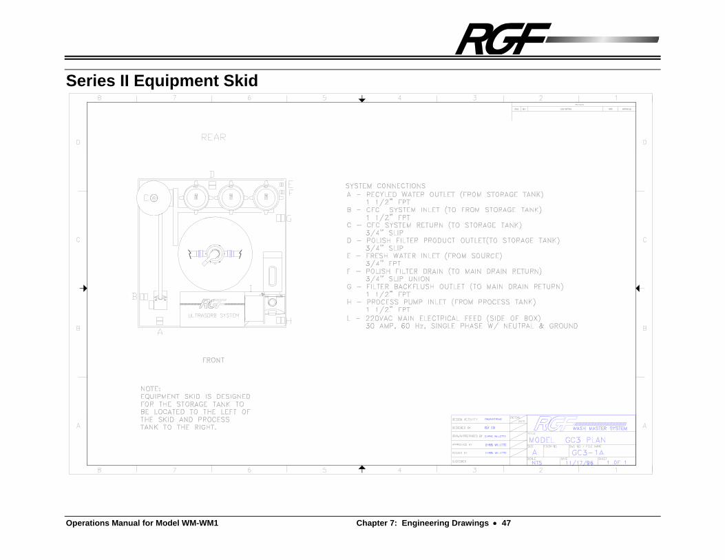
Series II Equipment Skid An engineered diagram of the Series II Equipment Skid which indicates all of the inlet and outlet connections and dimensions of the skid, as well as location of major components.
Series III Storage Tank An engineered diagram of the Series III Storage Tank which indicates all of the inlet and outlet connections and dimensions associated with the tank.
Plumbing & Instrumentation Diagram (P&ID) An engineered diagram which indicates the flow path of the system outlining placement and nomenclature of valves, pressure gauges and unions.
Electrical Diagram An engineered diagram of the electrical connections and components associated with the system. This diagram is a very useful tool for the electrician when the installation is performed.


Operations Manual for Model WM-WM1 Chapter 7: Engineering Drawings 45
Biosorb Series I

Operations Manual for Model WM-WM1 Chapter 7: Engineering Drawings 47
Series II Equipment Skid


Operations Manual for Model WM-WM1 Chapter 7: Engineering Drawings 49
Series III Storage Tank

Operations Manual for Model WM-WM1 Chapter 7: Engineering Drawings 51
Piping & Instrumentation Diagram


Operations Manual for Model WM-WM1 Chapter 7: Engineering Drawings 53
Electrical Ladder Diagram

Operations Manual for Model WM-WM1 Chapter 7: Engineering Drawings 55
Electrical Diagram


Operations Manual for Model WM-WM1 Chapter 8: Troubleshooting 57
Chapter 8: Troubleshooting Flow
SYMPTOM PROBABLE CAUSE SOLUTION
PROCESS SYSTEM 1. PROCESS PUMP
NOT OPERATING
A) POWER IS NOT APPLIED TO PUMP
B) PUMP HAS LOST
PRIME C) SYSTEM VALVES
ARE IMPROPERLY ALIGNED
A) VERIFY POWER IS APPLIED; THE PROCESS SYSTEM CONTROL SWITCH IS IN THE PROCESS POSITION AND THE BREAKER IS SHUT.
ENSURE FLOAT SWITCHES ARE PROPERLY POSITIONED, UNOBSTRUCTED AND FREE TO SWING AND ADEQUATE WATER IS IN BOTH SUCTION AND DISCHARGE TANKS
ENSURE THE PROPER ELECTRICAL CONNECTIONS WERE MADE TO THE SYSTEM. REFER TO THE PROCESS PUMP COMPONENT MANUAL.
B) VERIFY SYSTEM LINEUP. ENSURE UNOBSTRUCTED FLOW TO PUMP SUCTION. REPRIME PUMP ENSURING THAT PUMP CASING IS WATER FILLED. OPEN THE PRIMING PLUG AND RE-PRIME PUMP.
C) CONDUCT VALVE LINEUP WITH P&ID.
2. NO OR LOW FLOW THROUGH PROCESS SYSTEM
A) POLISH FILTERS ARE CLOGGED WITH PARTICULATE
A) PERFORM A POLISHING FILTER BACK FLUSH IN ACCORDANCE WITH PMS. IF THIS DOES NOT REMEDY PROBLEM THEN FILTERS ARE FOULED AND NEED TO BE REPLACED.
2. NO OR LOW FLOW THROUGH PROCESS SYSTEM
A) MULTI-MEDIA FILTER IS CLOGGED WITH PARTICULATE
B) POLISH FILTERS
ARE CLOGGED WITH PARTICULATE
A) PERFORM A MULTI-MEDIA FILTER BACK FLUSH IN ACCORDANCE WITH PMS. IF THIS DOES NOT REMEDY PROBLEM THEN FILTER IS FOULED AND NEEDS TO BE REPLACED.
B) PERFORM A POLISHING FILTER BACK FLUSH IN ACCORDANCE WITH PMS. IF THIS DOES NOT REMEDY PROBLEM THEN FILTERS ARE FOULED AND NEED TO BE REPLACED.

58 Chapter 8: Troubleshooting Operations Manual for Model WM-WM1
CFC SYSTEM 1. CFC PUMP NOT
OPERATING A) POWER IS NOT
APPLIED TO PUMP B) PUMP HAS LOST
PRIME C) SYSTEM VALVE IS
IMPROPERLY ALIGNED
A) VERIFY POWER IS APPLIED; BREAKER IS SHUT.
ENSURE THE PROPER ELECTRICAL CONNECTIONS WERE MADE TO THE SYSTEM. REFER TO THE CFC PUMP COMPONENT MANUAL.
B) CHECK WATER LEVEL IN STORAGE TANK. ENSURE UNOBSTRUCTED FLOW TO PUMP SUCTION. REPRIME PUMP ENSURING THAT PUMP CASING IS WATER FILLED. CONDUCT VALVE LINEUP WITH P&ID.
C) CONDUCT VALVE LINEUP WITH P&ID.
2. UV/O3 CHAMBER ON HOUSING IS OFF
A) OZONE GENERATOR IS DEFECTIVE
A) CALL YOUR DISTRIBUTOR OR RGF FOR FURTHER TROUBLESHOOTING ADVICE.
3. UV/O3 CHAMBER LEAKS
A) UV BULB RUBBER GROMMET IS IMPROPERLY SEATED.
B) UV CHAMBER IS OVER PRESSURIZED
C) INNER CHAMBER GLASS IS CRACKED OR BROKEN.
A) RE-SEAT BULB INTO GROMMET.
B) ENSURE UNOBSTRUCTED
FLOW. CONDUCT VALVE LINEUP WITH P&ID.
C) INNER CHAMBER MUST BE REPLACED.
4. CHEMICAL INJECTION PUMP NOT OPERATING CORRECTLY.
A) POWER IS NOT APPLIED TO PUMP
B) LOW OR EMPTY CHEMICAL CONTAINER.
C) SUCTION AND DISCHARGE HOSES ARE KINKED.
D) PUMP IS NOT
RUNNING.
A) CHECK FOR POWER TO THE PUMP.
B) FILL CHEMICAL CONTAINER WITH APPROPRIATE MIXTURE.
C) CHECK HOSES FOR KINKS. REMOVE PUMP FLEXIBLE HOSE REALIGN AND REPLACE.
D) CHECK CHEMICAL METERING KNOB FOR SETTING. IF NOT OFF, AND PUMP STILL NOT RUNNING, THEN PUMP IS DEFECTIVE.
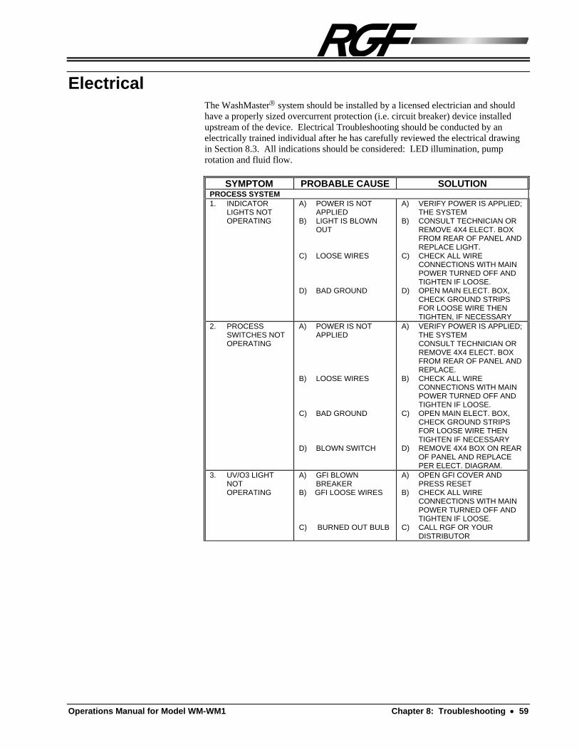
Operations Manual for Model WM-WM1 Chapter 8: Troubleshooting 59
Electrical The WashMaster system should be installed by a licensed electrician and should have a properly sized overcurrent protection (i.e. circuit breaker) device installed upstream of the device. Electrical Troubleshooting should be conducted by an electrically trained individual after he has carefully reviewed the electrical drawing in Section 8.3. All indications should be considered: LED illumination, pump rotation and fluid flow.
SYMPTOM PROBABLE CAUSE SOLUTION PROCESS SYSTEM 1. INDICATOR
LIGHTS NOT OPERATING
A) POWER IS NOT APPLIED
B) LIGHT IS BLOWN OUT
C) LOOSE WIRES D) BAD GROUND
A) VERIFY POWER IS APPLIED; THE SYSTEM
B) CONSULT TECHNICIAN OR REMOVE 4X4 ELECT. BOX FROM REAR OF PANEL AND REPLACE LIGHT.
C) CHECK ALL WIRE CONNECTIONS WITH MAIN POWER TURNED OFF AND TIGHTEN IF LOOSE.
D) OPEN MAIN ELECT. BOX, CHECK GROUND STRIPS FOR LOOSE WIRE THEN TIGHTEN, IF NECESSARY
2. PROCESS SWITCHES NOT OPERATING
A) POWER IS NOT APPLIED
B) LOOSE WIRES C) BAD GROUND D) BLOWN SWITCH
A) VERIFY POWER IS APPLIED; THE SYSTEM
CONSULT TECHNICIAN OR REMOVE 4X4 ELECT. BOX FROM REAR OF PANEL AND REPLACE.
B) CHECK ALL WIRE CONNECTIONS WITH MAIN POWER TURNED OFF AND TIGHTEN IF LOOSE.
C) OPEN MAIN ELECT. BOX, CHECK GROUND STRIPS FOR LOOSE WIRE THEN TIGHTEN IF NECESSARY
D) REMOVE 4X4 BOX ON REAR OF PANEL AND REPLACE PER ELECT. DIAGRAM.
3. UV/O3 LIGHT NOT OPERATING
A) GFI BLOWN BREAKER
B) GFI LOOSE WIRES C) BURNED OUT BULB
A) OPEN GFI COVER AND PRESS RESET
B) CHECK ALL WIRE CONNECTIONS WITH MAIN POWER TURNED OFF AND TIGHTEN IF LOOSE.
C) CALL RGF OR YOUR DISTRIBUTOR
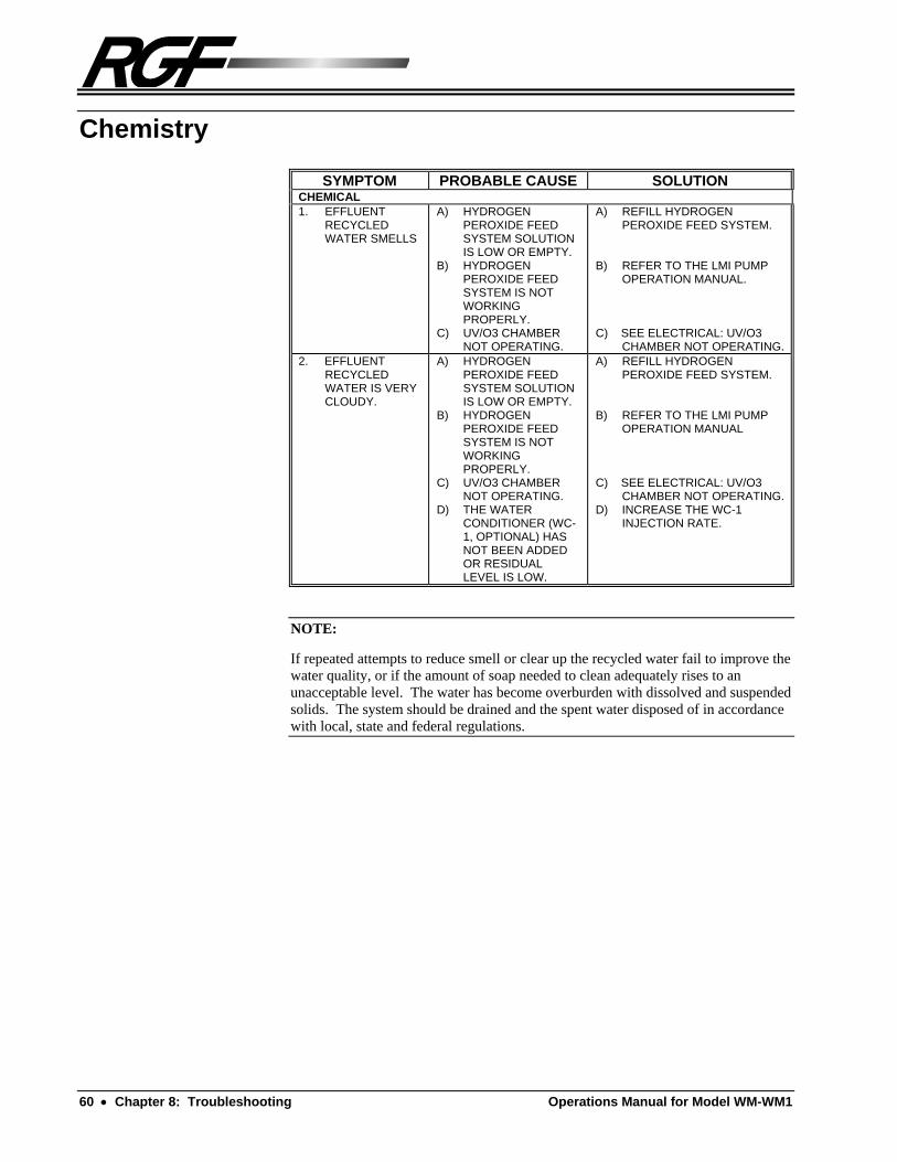
60 Chapter 8: Troubleshooting Operations Manual for Model WM-WM1
Chemistry
SYMPTOM PROBABLE CAUSE SOLUTIONCHEMICAL 1. EFFLUENT
RECYCLED WATER SMELLS
A) HYDROGEN PEROXIDE FEED SYSTEM SOLUTION IS LOW OR EMPTY.
B) HYDROGEN PEROXIDE FEED SYSTEM IS NOT WORKING PROPERLY.
C) UV/O3 CHAMBER NOT OPERATING.
A) REFILL HYDROGEN PEROXIDE FEED SYSTEM.
B) REFER TO THE LMI PUMP
OPERATION MANUAL. C) SEE ELECTRICAL: UV/O3
CHAMBER NOT OPERATING.2. EFFLUENT
RECYCLED WATER IS VERY CLOUDY.
A) HYDROGEN PEROXIDE FEED SYSTEM SOLUTION IS LOW OR EMPTY.
B) HYDROGEN PEROXIDE FEED SYSTEM IS NOT WORKING PROPERLY.
C) UV/O3 CHAMBER NOT OPERATING.
D) THE WATER CONDITIONER (WC-1, OPTIONAL) HAS NOT BEEN ADDED OR RESIDUAL LEVEL IS LOW.
A) REFILL HYDROGEN PEROXIDE FEED SYSTEM.
B) REFER TO THE LMI PUMP
OPERATION MANUAL C) SEE ELECTRICAL: UV/O3
CHAMBER NOT OPERATING. D) INCREASE THE WC-1
INJECTION RATE.
NOTE:
If repeated attempts to reduce smell or clear up the recycled water fail to improve the water quality, or if the amount of soap needed to clean adequately rises to an unacceptable level. The water has become overburden with dissolved and suspended solids. The system should be drained and the spent water disposed of in accordance with local, state and federal regulations.

Operations Manual for Model WM-WM1 Chapter 9: Replacement Parts 61
Chapter 9: Replacement Parts General Ordering Information
When preparing to order replacement parts for your system:
Have the Model # and Serial # of the unit ready when trying to order.
Have the ship to address ready.
Identify the part needed with the part # and description and call RGF or your local distributor to place an order.
Replacement Parts List
The following is a list of commonly needed replacement parts.
PART # DESCRIPTION
Filters and Parts FL-078 FILTER MEDIA FOR MULTI-MEDIA FILTER FP-073 MULTI-MEDIA FILTER VALVE ASSEMBLY FL-086 POLISHING FILTER CARTRIDGE (ONE) FP-51 O-RING FOR POLY FILTER HOUSING
Pumps and Parts PU-131 1/2 Hp. CFC SYSTEM PUMP PU-140 1-1/2 Hp. CENTRIFUGAL PROCESS PUMP PU-142 VITON SEAL FOR 1 1/2 Hp., PUMP PU-32 1/3 Hp. S.S. LIFT STATION SUMP PUMP PU-20 PUMP UP FLOAT SWITCH (30' CORD) PU-25 PUMP DOWN FLOAT SWITCH (30' CORD)
PU-129Y PERISTALTIC CHEMICAL INJECTION PUMP
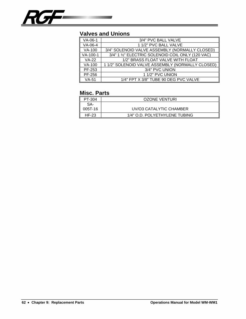
62 Chapter 9: Replacement Parts Operations Manual for Model WM-WM1
Valves and Unions VA-06-1 3/4" PVC BALL VALVE VA-06-4 1 1/2" PVC BALL VALVE VA-100 3/4” SOLENOID VALVE ASSEMBLY (NORMALLY CLOSED)
VA-100-1 3/4” 1 ½” ELECTRIC SOLENOID COIL ONLY (120 VAC) VA-22 1/2” BRASS FLOAT VALVE WITH FLOAT VA-100 1 1/2” SOLENOID VALVE ASSEMBLY (NORMALLY CLOSED)PF-253 3/4" PVC UNION PF-256 1 1/2" PVC UNION VA-51 1/4" FPT X 3/8" TUBE 90 DEG PVC VALVE
Misc. Parts PT-304 OZONE VENTURI
SA-005T-16
UV/O3 CATALYTIC CHAMBER
HF-23 1/4" O.D. POLYETHYLENE TUBING

Operations Manual for Model WM-WM1 Chapter 10: Sub-Component Manuals 63
Chapter 10: Sub-Component Manuals
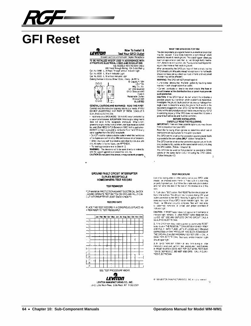
64 Chapter 10: Sub-Component Manuals Operations Manual for Model WM-WM1
GFI Reset

Operations Manual for Model WM-WM1 Chapter 10: Sub-Component Manuals 65
Process Pump

66 Chapter 10: Sub-Component Manuals Operations Manual for Model WM-WM1

Operations Manual for Model WM-WM1 Chapter 10: Sub-Component Manuals 67

68 Chapter 10: Sub-Component Manuals Operations Manual for Model WM-WM1
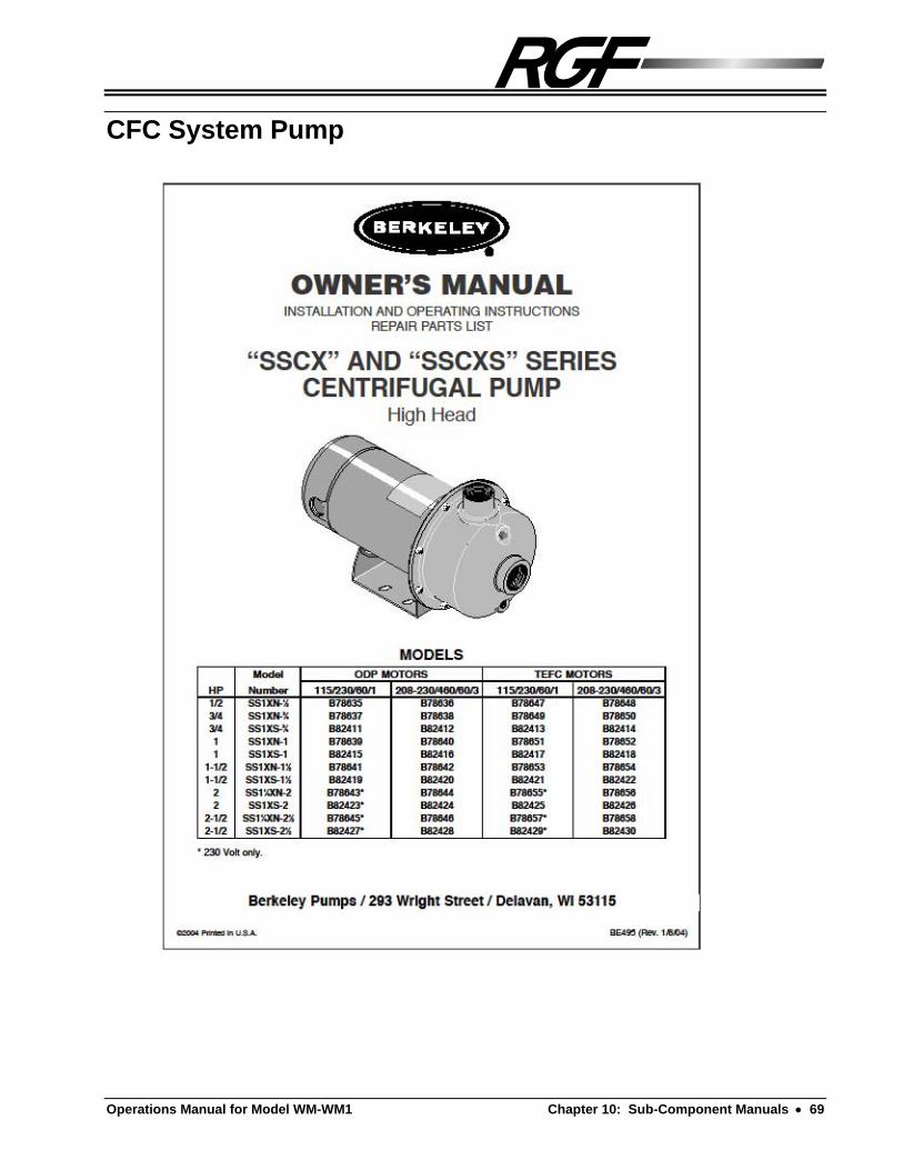
Operations Manual for Model WM-WM1 Chapter 10: Sub-Component Manuals 69
CFC System Pump
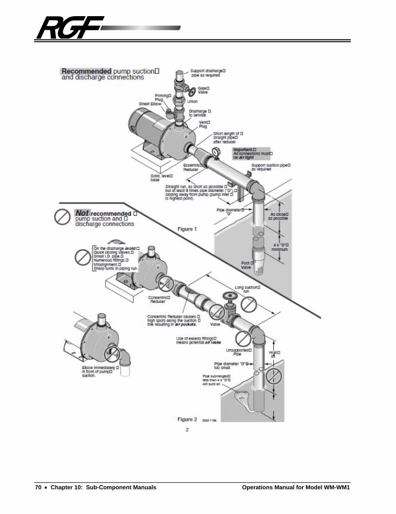
70 Chapter 10: Sub-Component Manuals Operations Manual for Model WM-WM1

Operations Manual for Model WM-WM1 Chapter 10: Sub-Component Manuals 71

72 Chapter 10: Sub-Component Manuals Operations Manual for Model WM-WM1

Operations Manual for Model WM-WM1 Chapter 10: Sub-Component Manuals 73

74 Chapter 10: Sub-Component Manuals Operations Manual for Model WM-WM1

Operations Manual for Model WM-WM1 Chapter 10: Sub-Component Manuals 75
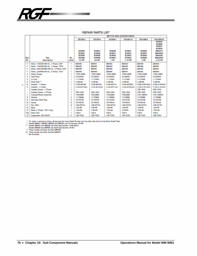
76 Chapter 10: Sub-Component Manuals Operations Manual for Model WM-WM1

Operations Manual for Model WM-WM1 Chapter 10: Sub-Component Manuals 77

78 Chapter 10: Sub-Component Manuals Operations Manual for Model WM-WM1

Operations Manual for Model WM-WM1 Chapter 10: Sub-Component Manuals 79

80 Chapter 10: Sub-Component Manuals Operations Manual for Model WM-WM1
Auto Backflush Timer

Operations Manual for Model WM-WM1 Chapter 10: Sub-Component Manuals 81

82 Chapter 10: Sub-Component Manuals Operations Manual for Model WM-WM1
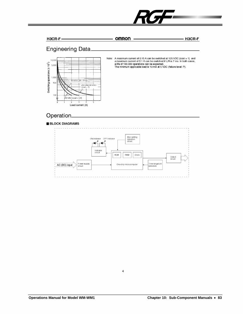
Operations Manual for Model WM-WM1 Chapter 10: Sub-Component Manuals 83

84 Chapter 10: Sub-Component Manuals Operations Manual for Model WM-WM1

Operations Manual for Model WM-WM1 Chapter 10: Sub-Component Manuals 85

86 Chapter 10: Sub-Component Manuals Operations Manual for Model WM-WM1
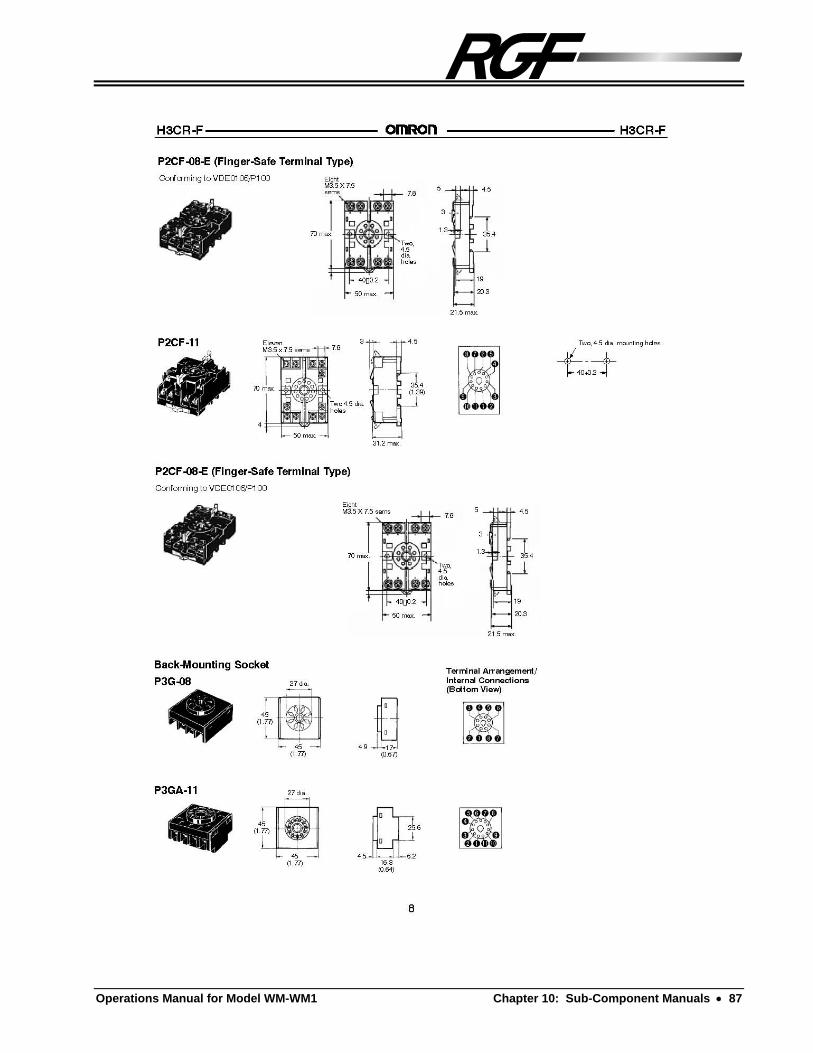
Operations Manual for Model WM-WM1 Chapter 10: Sub-Component Manuals 87
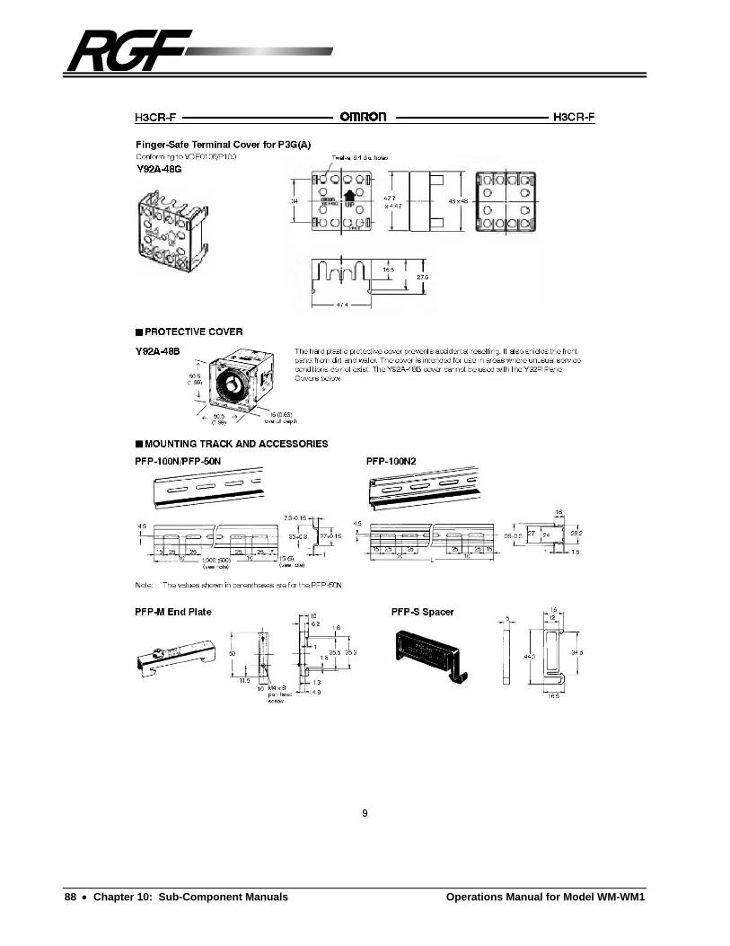
88 Chapter 10: Sub-Component Manuals Operations Manual for Model WM-WM1

W-1
System Warranty
ULTRASORB System Limited Warranty
This warranty supersedes and replaces any warranty statements orally made by the Sales Person, Distributor, or Dealer or contained in written instructions or other Brochures or informational documents in relation to this product. THERE ARE NO WARRANTIES WHICH EXTEND BEYOND THE DESCRIPTION ON THE
FACE HEREOF The Manufacturer Warrants, parts only for a period of twelve (12) months from the time of startup, not to exceed fourteen (14) months from the date of shipment, the new ULTRASORB System to be free from defects in material and workmanship under the normal use and service when operated and maintained in strict accordance with the ULTRASORB System operating instructions. The Manufacturer's obligations under this warranty is being limited to repairing or replacing any part found to its satisfaction to be so defective, provided that such part is, upon request, returned to the Distributor or Manufacturer, with freight prepaid. This warranty does not cover parts damaged by decomposition from chemical action or wear caused by abrasive materials, nor does it cover damage resulting from misuse, abuse, or any other than its intended use, accident, neglect, or from improper operation, maintenance, installation, modification or adjustments. This warranty does not cover parts or equipment used with the ULTRASORB System that are not made by the manufacturer, since these items are covered by warranties from the respective manufacturer. The Manufacturer makes no warranty as to electrical apparatus or other materials not of its manufacturer. The Manufacturer's sole responsibility shall be limited to repair or replacement of the equipment within the terms stated herein above.


W-2
The Manufacturer shall not be liable for consequential or punitive damages whether or not caused by manufacturer's negligence or resulting from any expressed or implied warranty or breach thereof. Consequential damages for the purpose of this agreement shall include, but are not limited to, the loss of use, income or profit, or loss of or damage to property occasioned by or arising out of in-operation, use, the operation, installation, repair, or replacement of the equipment or otherwise. It is understood that any controversy or claim arising out of or relating to the ULTRASORB System Warranty herein or the alleged breach thereof, shall be settled by arbitration in accordance with the rules of the Arbitration Association of America, Palm Beach County, Florida, and judgment upon the award rendered by the arbitrator(s) may be entered in any court baring jurisdiction thereof.
PROCESS PERFORMANCE WARRANTY
The Manufacturer Warrants that when installed and operated in accordance with the Manufacturer's
written instructions, the ULTRASORB System will remove dirt, oil, and grease from wash water. No other warranty expressed or implied should be considered valid. There are numerous operating
conditions which will affect the efficiency of the ULTRASORB System, thereby making any general water quality statement unrealistic.
WARRANTY SERVICE In order to validate your warranty, fill out the Warranty Validation Form and return to RGF at the address below: RGF WARRANTY DEPARTMENT Outside of Florida (800) - 842 - 7771 In Florida (561) - 848 - 1826 or FAX (561) - 848 - 9454 To obtain warranty service contact RGF and a warranty representative will help with the warranty problem and determine the status and a Warranty Authorization Number will be given at that time. Be prepared to answer specific questions on the problem at hand. If there are warranted parts that need to be returned, fill in the Warranty Authorization Number on the Warranty Request Form along with the items being submitted for warranty and an brief explanation of the problem or defect and return it and the part(s) to: RGF Environmental Group, Inc. c/o Warranty Department 1101 West 13th Street Riviera Beach, Florida 33404

WP-3
ULTRASORB System Limited Warranty Policy
RGF ENVIRONMENTAL GROUP, INC. ["Manufacturer"] Warrants the ULTRASORB System to be free from DEFECTS in Material and Workmanship. HOW LONG IS THE WARRANTY? For twelve (12) months from the date of initial startup of the system; not to exceed fourteen (14)
months from the date of delivery. The Installation / Startup Record and Warranty Registration Form should be signed and dated by an
authorized officer or employee of the customer and returned to RGF promptly to activate the warranty.
HOW DO I CONTACT RGF ENVIRONMENTAL GROUP ABOUT MY WARRANTY, A QUESTION, OR A COMPLAINT? A question or a complaint mat be addressed directly by your local Distributor or dealer. If they can not answer the question or complaint directly, then call or FAX the Warranty
Department at RGF at: RGF WARRANTY DEPARTMENT Outside of Florida (800) - 842 - 7771 In Florida (561) - 848 - 1826 or FAX (561) - 848 - 9454

ARE THERE ANY PARTS THAT ARE NOT COVERED BY THIS WARRANTY? (That the Manufacturer will not repair or replace) Parts that are damaged by decomposition from chemical action or wear caused by abrasive
materials, nor does it cover damage resulting from misuse, abuse, any other than it's intended use, accident, neglect, or from improper operation, maintenance, installation modification or adjustments.
Parts not made by the Manufacturer, such as the electric pressure pump motor or other materials
not of it's manufacturer. However, RGF will process the claim with the pump or other manufacturer.
WHAT SHOULD BE DONE IN THE EVENT THAT THE EQUIPMENT IS DAMAGED BY SHIPPING? Immediately upon receipt of the system, the purchaser is responsible to take the shipping
containers off of the truck and inspect the equipment and parts for damage. If there is any visible damage to the equipment: 1. Notify the driver of the courier company immediately and write on the Bill of Lading what
is damaged or missing. 2. Call RGF immediately at 1 - (800) - 842 - 7771 outside of Florida, 1 - (561) - 848- 1826 in
Florida, or FAX 1- (561) - 848 - 9454. WHAT IF DAMAGE IS FOUND ON THE EQUIPMENT AFTER THE COURIER HAS LEFT? Claims for concealed shipping damage must be reported to the courier and a copy sent to RGF in
writing via FAX 1 - (561) 848 - 9454 or certified U.S. mail within fifteen (15) days from the date of delivery.
NOTE: The courier company will not cover the damages if the foregoing steps are not adhered to. STEPS THAT SHOULD BE TAKEN IF WARRANTY WORK OR REPLACEMENT IS NEEDED. Call your local distributor or RGF Warranty Department and notify them of the problem or
malfunction. Be prepared to be very descriptive with the problem. If it is determined that a part has malfunctioned due to defect, a Warranty Authorization
Number will be given for tracking the part. Fill out the Warranty Request Form along with the Warranty Authorization number and return it along with the defective part prepaid to:
RGF Environmental Group, Inc c/o Warranty Department 1101 West 13th Street Riviera Beach, Florida 33404


THINGS THAT SHOULD BE DONE TO HELP KEEP THE ULTRASORB SYSTEM RUNNING EFFICIENTLY. Read the Operations Manual thoroughly. Make sure all of the employees who operate the system are fully trained on the procedures for
operating the system and follow preventive maintenance routines strictly. Do not run water that has contaminants through the system that it is not designed to remove. Make sure the system is operated in accordance with the Manufacturer's suggested instructions. Replace filters as recommended in the Operations Manual. Control the water quality in accordance with RGF's suggested guidelines. Keep sump pits, trenches, and weirs cleared of heavy sediment build up. Heavy solids build up
will cause the sump pump to overheat and fail to operate properly. Failure to prevent this will void the sump pumps warranty.
Lack of a water clarifier (such as hydrogen peroxide, chlorine, WC-1, Ozone, etc.) will cause
algae to grow resulting in plugged filters and foul smell. WHAT SERVICE CAN IS EXPECTED FROM THE DISTRIBUTOR? The Distributor will install, perform the initial startup, and train your personnel. Should there be any questions relating to this warranty policy information, please feel free to contact our customer service representative at: RGF Customer Service Outside of Florida (800) - 842 - 7771 In Florida (561) - 848 - 1826 FAX (561) - 848 - 9454 or Write RGF Environmental Group, Inc. c/o Customer Service Dept.
1101 West 13th Street Riviera Beach, FL 33404

WP-3
Product Registration and Return Forms

ULTRASORB System Warranty Request Form
NOTE: THIS FORM MUST BE COMPLETED AND ACCOMPANY ALL RETURNED ITEMS
Warranty Authorization Number: W-____________________________
CUSTOMER: NAME ADDRESS PHONE FAX DISTRIBUTOR: NAME ADDRESS CONTACT UNIT: MODEL SERIAL # DATE OF PURCHASE ITEMS BEING SUBMITTED FOR WARRANTY:
PLEASE LIST THE PARTS AND GIVE A BRIEF DESCRIPTION OF THE PROBLEM.
ITEMS 1) 2) DESCRIPTION (COMMENTS) 1) 2) 3) SHIP TO: RGF ENVIRONMENTAL GROUP, INC. c/o WARRANTY DEPTMENT 1101 West 13th Street RIVIERA BEACH, FLORIDA 33404 FAX 561-848-9454
(FOR RGF USE ONLY)
DATE ITEMS RECV'D
RECEIVED BY
REPLACEMENT PART SENT/WARRANTY APPROVED WARRANTY DENIED


ULTRASORB System Warranty Validation Form
To validate the Warranty for the system, this form must be read, signed and returned to: RGF Environmental Group, Inc c/o Warranty Department 1101 West 13th Street Riviera Beach, Florida 33404 FAX 561-848-9454
1. I have inspected the system upon arrival for shipping damage and have reported any problems to the local
distributor, the courier company, or RGF within the required time period. 2. I have been provided with training on the operation and procedures for the system by the distributor or RGF
representative, during the installation and startup of the system. 3. I understand it is the customer's responsibility to:
Regularly monitor and maintain the water chemistry of the system and to utilize properly only any chemicals
or cleaning agents that are compatible with the equipment. To regularly clean out the sump pit and perform suggested preventive maintenance on the system in order to
keep the system in good working order. I understand that failing to do so will adversly effect the efficiency of the system. I also understand, that it is my responsibility to properly dispose of the used filters, pit sediment, and any other by-products accordingly.
Protect the system from extreme (high/low) temperatures to prevent damage to the components and piping of the system.
Notify the local distributor or RGF Warranty Dept. immediately upon any malfunction of the system in order to receive warranted work or parts.
4. I understand that any controversy or claim arising out of or relating to the ULTRASORB System Warranty
herein or the alleged breach thereof, shall be settled by arbitration in accordance with the rules of the Arbitration Association of America, Palm Beach County, Florida, and judgment upon the award rendered by the arbitrator(s) may be entered in any court baring jurisdiction thereof.
I hereby acknowledge the above. Customers Name ___________________________ Address ___________________________ ___________________________ Signature Date


ULTRASORB System Installation / Startup Record
Model Number Installation Date
Serial Number Start-Up Tech.
Distributer Customer
Address
Phone ( ) FAX ( ) Contact
Names of Trainees Position Initials
What is Being Cleaned Hr's. Per Day
Washpad Design & Const. By?
Is the Washpad Satisfactory? Yes ___ No ___ If No, Explain
Was the Unit Missing Parts? Yes ___ No ___ If Yes, Explain
Did the Unit Have Shipping or Hidden Damage? Yes ___ No ___ If Yes, Explain
List Any Options/Modifications with this Unit.


ULTRASORB System Installation / Startup Checklist
MAINTENANCE PROCEDURES, CHECK IF COVERED & APPLICABLE
Overall System Description Sump Pump & Maintenance EPA & Sewer Rules Electrical, Shutoffs, Etc. Wash Pad Maintenance Centrifugal Separator Solids Cleaning Procedure Oil Accumulator Bleed Lines Coalescing Tubes Solids Grid Hydrocarbon Absorber II Filter Media Centrifugal Pump Hydrocarbon Absorber III Chlorinator Jet Pump and Switch Fresh Water Make-up TurboHydrozone Air Compressor Polishing Filters Pressure Gauges Pressure Tank 3 Way Control Valve Options: Options: Options: Options:
CRITICAL FUNCTIONS AND PROCEDURE DISCUSSIONS
Basic Water Chemistry; Operator Safety; pH, Alkalinity, TDS Clothing, Ventilation, Etc. Algae/Bacteria Control; Cleaning Agents; Enviro- Chlorine, Hydrogen Peroxide Control, Ultra-Safe Water Cycling, WC1 Water Management Water Testing; ETS Kit, Recycled / Fresh Water pH Paper, TDS Meter Where to Get Help; Manuals, Distributor, RGF
CUSTOMER HANDOUTS AND SUPPORT MATERIAL
Operating Manuals Water Test Kit Maintenance Video Spare Parts List
CUSTOMER EVALUATION OF START-UP TRAINING: How Would You Rate Your Training? Good ___ Fair ___ Poor ___ General Comments RGF Tech. Rep. Signature Trainees Signature


Operations Manual for Model WM-WM1 Product Registration and Return Forms 105
ULTRASORB System
Client Questionnaire
Company Name Contact Person Location Phone ( ) RGF Dealer/Salesman Purchase Date (approx.) Model Serial Number HOW WOULD YOU RATE THE FOLLOWING: GOOD FAIR POOR General Operation Recycled Water Quality Quality of System Service & Support Warranty Installation / Training Safety RGF Dealer / Salesman Value Would you purchase another RGF System? Yes ___ No ____ Comments Completed By: Date Please return this form to: RGF Environmental Group, Inc. c/o Customer Service Dept. 1101 West 13th Street Riviera Beach, FL 33404 Fax: 516-848-9454 -

106 Glossary of Terms Operations Manual for Model WM-WM1
Glossary of Terms Aeration Tower Tall 2" dia. PVC pipe on the Series I Tank used to mix air into the waste stream to enhance oil separation and remove V.O.C.'s (volatile organic compounds).
Back Flush Cartridge Filter A small cartridge filter used to remove any solids from the back flush water which may clog the MS3 Membranes or Polishing Filters during back flushing.
CFC System Pump A continuous flow control centrifugal pump used to circulate the recycled water through the CO3P System (Chemical Injection, Ozone Venturi and UV/O3 Catalytic Chamber) and supplies the water to the cleaning equipment.
CO3P system (Catalytic Oxidation Process) System of low cost oxidant production is designed to provide a hydroxyl radical for contaminated water treatment. This system utilizes ozone, UV and hydrogen peroxide to create a hydroxyl radical ion for maximum oxidation and biodegradation.
Control Panel Contains all the controls for the system: flow control valves, pressure gauges, indicator lights, and the hour meter.
H.I.P. Absorber An absorption media filter designed to remove herbicides, insecticides and pesticides from the recycled water stream.
HCA-3 Absorber Housed in a polyethylene vessel, is a hydrocarbon absorber used as a final measure of removing oils before the water is processed through the Polishing Filters or MS3 Membranes. The Absorber consists of two highly absorbent medium, polyisocyanurate and fibrous polypropylene, to absorb low micron particles of oils, fuels, solvents, and hydrocarbons.
Main Drain Return Line A recommended method of returning the drains of the system to the front end of the trench system. This line should be sized accordingly to accommodate the system drains.
Operations Manual for Model WM-WM1 Glossary of Terms 107
Ozone and Chemical Venturi A venturi used in the CO3P system, which draws ozone produced by the UV/O3 Catalytic Chamber and mixes it with the hydrogen peroxide before it enters the chamber.
Polishing Filter Housed in a polypropylene vessel, used to pre-filter the water before it is processed through the rest of the system.
Process Pump A centrifugal pump located on the equipment rack of the Series II Equipment Skid, pumps the process water through the specific filters of the system.
Series II Electrical Junction Box Contains all the electrical relays, timers and terminals for the system and connects them to the motors, lights, switch and UV chambers of the system.
Series II Equipment Skid Contains all of the components of the system for processing the water.
Series III Storage Tank A 500 (or 800) gallon cylindrical polyethylene tank used to store the recycled water for later use.
UV/O3 Catalytic Chamber The new UV/O3 combination chamber produces over three times the ozone and approximately twice the ultraviolet radiation as our initial design. When these two components of the CO3P process are combined into one unit, they become more effective, efficient and compact.