Operationalizing Synchrophasors for Enhanced …. Baone GE...INSERT ORG LOGO (Optional)...
25
Operationalizing Synchrophasors for Enhanced Electric Grid Reliability and Asset Utilization Chaitanya A. Baone GE Global Research [email protected] June 13, 2017 Washington, DC DOE/OE Transmission Reliability Program
Transcript of Operationalizing Synchrophasors for Enhanced …. Baone GE...INSERT ORG LOGO (Optional)...

INSERT ORG LOGO (Optional)
Operationalizing Synchrophasors for Enhanced Electric Grid
Reliability and Asset Utilization
Chaitanya A. BaoneGE Global Research
[email protected] 13, 2017
Washington, DC
DOE/OE Transmission Reliability Program

INSERT ORG LOGO (Optional)
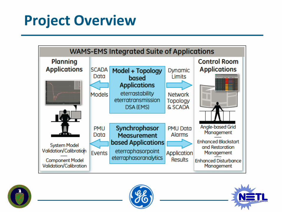
Overall Project Objectives
• Develop and demonstrate multiple production-grade synchrophasor applications to enhance system planning and operations
• Designed to enhance grid reliability and asset utilization through utilization of existing WAMS infrastructure along with EMS network applications available at control rooms
• Project includes field demonstrations at multiple utility locations
INSERT ORG LOGO (Optional)
Project Overview

INSERT ORG LOGO (Optional)
Project Overview
• Develop and demonstrate three Synchrophasor Applications:
1. Model Validation/Calibration tool for improving models to meet emerging NERC requirements
2. Angle-based grid management (AGM) tool for improved transmission asset utilization in voltage stability limited systems
3. Operator guidance tool for enhanced blackstart/restoration and disturbance management
• Two phases: Phase I – R&D, Phase II – Factory Acceptance Testing and Field Demonstration
• Project duration: March, 2017 – March, 2019
INSERT ORG LOGO (Optional)
Disturbance based Model Validation/Calibration
• Production-grade software tool for disturbance based model validation/calibration
• Design approach driven by industry challenges associated with model validation/calibration
• Leverage GE’s engineering analysis WAMS software platform to build this application
• Software application will have API’s to interface with GE PSLF, Powertech TSAT simulation tools
• Solution generic enough to be applicable to wide variety of models (traditional generating plant, wind, solar, dynamic load, etc.)

INSERT ORG LOGO (Optional)
• Key considerations to ensure successful model validation/calibration:
1. Account for non-linearity in models
2. Account for multiple different events
3. Physical constraints of parameters need to be enforced during model calibration
4. Calibration results may be strongly dependent on assumed default parameter values
5. Avoid tuning parameters that may already be at their true values
Disturbance based Model Validation/Calibration

INSERT ORG LOGO (Optional)
• Parameter identifiability analysis to determine the set of identifiable parameters across a range of events and default values
• Candidate calibration algorithms
– Unscented Kalman Filter (UKF)
– Optimization-based Calibration
Disturbance based Model Validation/Calibration
PMU data from
events
Set of Identifiable Parameters
Dynamic Simulation Engine (PSLF/TSAT)
𝑃, 𝑄
𝑉, 𝑓
𝑃, 𝑄
𝛥 Parameters𝑃, 𝑄, auxiliary quantities
𝛥 Parameters
Model CalibrationAlgorithm
Parameter Identifiability
Analysis

INSERT ORG LOGO (Optional)
Model Validation/Calibration on 2-area System
Target Generating Plant
PMU location(Feed playback data here)
Rest of the system(Its dynamic behavior is recorded in playback data)

INSERT ORG LOGO (Optional)
Parameters Subject to Tune (PST Model)
• Generator Parameters (6th order model):
• Exciter Parameters (1st order model):
• Governor Parameters (3rd order model):
p1 p2 p3 p4 p5 p6 p7 p8 p9 p10 p11 p12 p13 p14 P15
xl ra xd x'd x"d T'do T"do xq x'q x"q T'qo T"qo H D0 D1
p16 p17 P18
Tr Ka Ta
p19 p20 p21 p22 p23 p24
R Ts Tc T3 T4 T5

INSERT ORG LOGO (Optional)
Parameter Identifiability using Sensitivity Analysis
Output sensitivities to different parameters
• Difficult to recognize dependency without data analysis
• Two aspects to be considered:– Magnitude of output sensitivity to parameter changes
– Dependency among multiple parameter sensitivities

INSERT ORG LOGO (Optional)
Parameter Identifiability Spiral Graph
• Sensitivity magnitude: reduces in counter-clockwise direction
• Sensitivity dependency: represented by connecting lines
P-spiral Q-spiral

INSERT ORG LOGO (Optional)
Accounting for Multiple Events• Different events may result in different parameter sensitivities
Event A Event B
Sensitivity Analysis B
Sensitivity Analysis A

INSERT ORG LOGO (Optional)
P,Q-spiral for Multiple EventsEvent A Event B Event C
P-spiral
Q-spiral
P-spiral
Q-spiral
P-spiral
Q-spiral

INSERT ORG LOGO (Optional)
UKF based Model Calibration
Power system model(PSLF/TSAT)
• Compute sigma points based on covariance/std. deviation information
• Compute Kalman Gain matrix 𝐾, based on ො𝑦
• Update the parameters𝑥𝑘 = 𝑥𝑘−1 + 𝐾(𝑦𝑚 − ො𝑦)
• Quit when 𝑥𝑘 converged
Measured input/output
𝑢, 𝑦𝑚
Estimated parameters
𝑥𝑘 ො𝑦
GE WAMS Platform

INSERT ORG LOGO (Optional)
Preconditioning for UKF (PST model)Ev
ent
AEven
t B
Q-spiral
P-spiral P-spiral
Q-spiral
• p1, p3, p6, p9, p11, p17 are less identifiable for event A than for event B

INSERT ORG LOGO (Optional)
UKF based Model Calibration (PST model)
Parameters to tune: p1, p3, p6, p9, p11, p17
Event A Event B
P
Q Q
P
Time Samples Time Samples

INSERT ORG LOGO (Optional)
Event A Event BP Error
Q Error Q Error
P Error
Default True Tuned
P1 (Xl) 0.24 0.2 0.1847
P3 (Xd) 3.6 1.8 2.099
P6 (T’do) 16 8 7.332
P9 (X’q) 1.1 0.55 0.5353
P11 (T’qo) 0.8 0.4 0.4058
P17 (Ka) 400 200 182.04
Default True Tuned
P1 (Xl) 0.24 0.2 0.2001
P3 (Xd) 3.6 1.8 1.8016
P6 (T’do) 16 8 8.0169
P9 (X’q) 1.1 0.55 0.5527
P11 (T’qo) 0.8 0.4 0.3993
P17 (Ka) 400 200 200.59
UKF based Model Calibration (PST model)

INSERT ORG LOGO (Optional)
UKF based Model Calibration (PSLF model)
• Hydro Power Plant Model*:gentpj – Synchronous Generator Modelesst1a – Bus-fed Static Excitation Systemieeeg3 – IEEE Type 3 Turbine-Governorpss1a – Analog Single-Input Stabilizer
• GE PSLF as the simulation tool• Use recorded PMU data* for
playback simulation
* Courtesy: BPA TIP 352 project

INSERT ORG LOGO (Optional)
Measured – TrueUKF – EstimatedInitial – Corrupt
UKF based Model Calibration (PSLF model)

INSERT ORG LOGO (Optional)
MODELPARAMETER
NAME
DEFAULT/
CORRUPTTRUE UKF ESTIMATED
gentpj tpdo 4.3 6.17 3.78
gentpj h 4 5.5 5.31
gentpj ld 0.55 0.67 0.28
esst1a tc 2.1 0.9 0.84
esst1a tb 2.5 3.85 2.67
esst1a ka 50 125 68.5
ieeeg3 rperm 0.05 0.065 0.069
ieeeg3 rtemp 0.24 0.42 0.58
ieeeg3 tr 1.2 2.4 1.92
pss1a a1 0.035 0.035 0.017
pss1a t5 15 10 9.81
pss1a t6 0.035 0.035 0.017
pss1a ks 35 20 21.09
Initial evaluation suggests UKF performs well with respect to P, Q match as well as parameter match
UKF based Model Calibration (PSLF model)

INSERT ORG LOGO (Optional)
Key Milestones in Phase I (R&D)
Key Milestones in Phase IYear 1 Year 2
Apr-Jun
Jul-Sep
Oct-Dec
Jan-Mar
Apr-Jun
Jul-Sep
Oct-Dec
Jan-Mar
Model Validation/Calibration ToolModel validation/calibration functional specification
Model validation/calibration developed and tested with simulated data
Model validation/calibration software platform integration with commercial simulation tools (PSLF, TSAT)
Angle-based Grid Management (AGM) ToolAGM functional specification
AGM algorithm developed and tested with simulated data
AGM software platform integration
Operator Guidance ToolOperator guidance tool functional specification
Operator guidance algorithm developed and tested with simulated data
Operator guidance software platform integration
INSERT ORG LOGO (Optional)
Project Status & Accomplishments
• Accomplishments so far:– Development of a parameter identifiability tool for successful
model calibration
– Evaluation of multiple candidate model calibration techniques, including successful demonstration using realistic models & data
– Patent disclosure for novel model calibration approach
– IEEE paper on model calibration approach in progress
– Initial evaluation of angle-based grid management for voltage stability limited systems
• Deliverables for this year:– Quarterly reports, annual report describing developed algorithms
and validation results with simulation data

INSERT ORG LOGO (Optional)
Next Steps
Year 1:
• Finalize functional specifications for all three software applications in consultation with utility partners
• Rigorous testing and validation of developed algorithms
• Software architecture design and platform integration
• Data sharing agreements with all utility partners
Year 2:
• Field demonstration planning and preparation
• Factory acceptance testing and algorithm tuning
• Field demonstrations at utility host locations

INSERT ORG LOGO (Optional)
Thank You!