Operational Amplifiers 1
31
Operational Amplifiers
Transcript of Operational Amplifiers 1

Operational Amplifiers

Agenda• Introduction• Background• Amplifier Introduction• Basic Circuits Review• Characteristics of an Ideal Op Amp• Types of Op Amps• Practical Applications• Conclusion• Quiz

Introduction
• Operational Amplifiers are represented both schematically and realistically below:– Active component!

Background
• Originally invented in early 1940s using vacuum tube technology– Initial purpose was to execute math operations in analog
electronic calculating machines
• Shrunk in size with invention of transistor• Most now made on integrated circuit (IC)
– Only most demanding applications use discrete components
• Huge variety of applications, low cost, and ease of mass production make them extremely popular

Amplifiers
• Differential Amplifier– Amplifies difference
between inputs
Single-ended Amplifier

Operational Amplifier• Output gain high
– A ~= 106 • Tiny difference in the input
voltages result in a very large output voltage– Output limited by supply
voltages• Comparator
– If V+>V-, Vout = HVS– If V+<V-, Vout = LVS– If V+=V-, Vout = 0V

3-stage Op-Amp

Why are they useful?
• Sensor signals are often too weak or too noisy– Op Amps ideally increase the signal amplitude
without affecting its other properties

Why are they useful?
• Negative feedback leads to stable equilibrium• Voltage follower (direct feedback)
– If Vout = V- , then Vout ~ V+
Closed Loop Transfer Function
H(s) = A / (1 + AF)
When AF >> 1…
H(s) = 1 / FWhere: A = Op Amp Open Loop Gain
F = Feedback Loop Gain

1. The output attempts to do whatever is necessary to make the voltage difference between the inputs zero.
2. The inputs draw no current.

Basic Circuits Review
• Kirchoff’s Law– Voltage Law: The sum of
all the voltage drops around the loop = Vin
• Resistance (Ohms – Ω)– Series
– Parallel
V1 + V2 + V3 = Vin

Basic Circuits Review
• Capacitance (Farad – F)– Series
– Parallel
• Inductance (Henry – H)– Series
– Parallel

Ideal Op Amp
• Zin is infinite
• Zout is zero
• Amplification (Gain) Vout / Vin = ∞• Unlimited bandwidth• Vout = 0 when Voltage inputs = 0

Ideal Op Amp
Ideal Op-Amp Typical Op-Amp
Input Resistance infinity 106 (bipolar)109 - 1012 (FET)
Input Current 0 10-12 – 10-8 A
Output Resistance 0 100 – 1000
Operational Gain infinity 105 - 109
Common Mode Gain 0 10-5
Bandwidth infinity Attenuates and phases at high frequencies (depends on slew
rate)
Temperature independent Bandwidth and gain

How are Op-Amps used?
• Comparator (seen earlier)• Voltage follower (seen earlier)• Signal Modulation• Mathematical Operations• Filters• Voltage-Current signal conversion

Non-inverting Op-Amp
Uses: Amplify…straight up
www.wikipedia.org

Inverting Op-Amp
Uses: Analog inverter
www.wikipedia.org
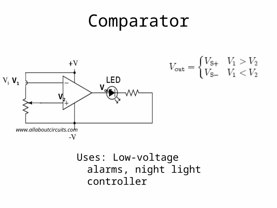
Comparator
www.allaboutcircuits.com
Uses: Low-voltage alarms, night light controller
V2
V1 Vout

Pulse Width Modulator
• Output changes when – Vin ~= Vpot
• Potentiometer used to vary duty cycle
www.allaboutcircuits.com Uses: Motor controllers

Summation
Uses: Add multiple sensors inputs until a threshold is reached.
www.wikipedia.org

Difference
1
31
124
4132
)( RRV
RRRRRRV
Vout
12 VVVout
If all resistors are equal:

Integrating Op-Amp
Uses: PID Controller
www.wikipedia.org

Differentiating Op-Amp
(where Vin and Vout are functions of time)
www.wikipedia.org
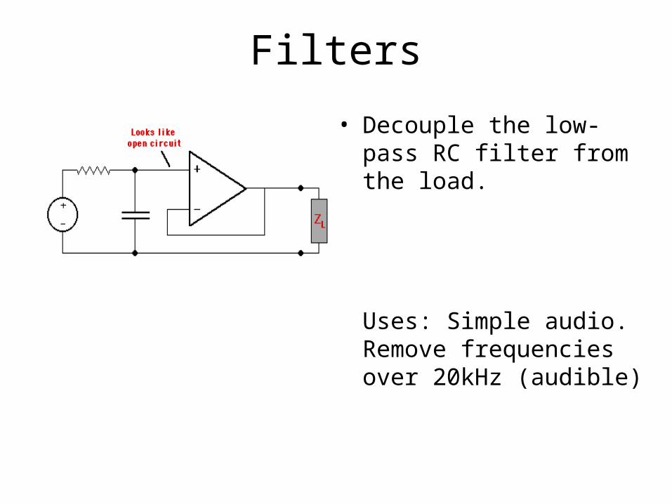
Filters
• Decouple the low-pass RC filter from the load.
Uses: Simple audio. Remove frequencies over 20kHz (audible)

Low-pass Filter (active)
• Cutoff frequency
• This works because the capacitor needs time to charge.
www.wikipedia.org

High pass filter (active)
Band-pass filter cascades both high-pass and low-pass!
www.wikipedia.org

Measuring current
• Current (I) better than voltage (V) for measurement– Voltage suffers losses due to resistances in path– Low impedance is better for resisting noise
• So how do we generate a constant current source?– Transconductance Amplifier

Transconductance Amp
• Precision 250Ω resistor• 1V / 250 Ω = 4mA• 5V / 250 Ω = 20mA• RLoad doesn’t matter, just
as long as op-amp has high enough voltage rails
Uses: - In: Sensors (temp, pressure, etc), - Out : Radios (Variable Freq Osc)
www.allaboutcircuits.com

Conclusions
• Op-Amps are often used for– Sensor amplification– Mathematical operations (sums, difference,
inverse)– Filters (High/Low/Band pass)– Measurement devices
• Current in –> Voltage out

Questions?
• Does an Op-Amp amplify current or voltage?• Can you use an Op-Amp as a buffer? If so, How?• Why should you care about the device bandwidth
rating?• What is the most common Op Amp chip?• What is an ‘active’ component? Is an Op Amp an
active or a passive component?• What is the advantage of an active vs. passive filter?
Practical Tips
• Try to use single supply op-amps in order to minimize need for a 10V difference from power supply
• Good low resistance, twisted, and shielded wire should be used when a sensor is located far away from the op-amp circuit.
• Minimize current draw in sensor circuits to reduce thermal drift• Filter power into op-amp circuits using capacitors• Design op-amp circuits so output cannot be negative in order to protect
68HC11 A/D port.• Isolate op-amp circuit output with unity gain op-amp if connected to an
actuator.• Make sure bandwidth of op-amp is adequate• Use trimmer potentiometers to balance resistors in differential op-amp
circuits• Samples of op-amps can be obtained from National Semiconductor
(http://www.national.com)