OPERATION MANUAL - LaboModerne · This operation manual consists of the following chapters covering...
51
(Form: CE-014a-01) No. S10G-000-A OPERATION MANUAL AUTOCLAVE HICLAVE HGD-113 , HGD-133 ● Read this manual carefully and follow the instructions to use the equipment correctly. Issued on May 8, 2010 IMPORTANT
Transcript of OPERATION MANUAL - LaboModerne · This operation manual consists of the following chapters covering...

(Form: CE-014a-01)
No. S10G-000-A
OPERATION MANUAL
AUTOCLAVEHICLAVE
HGD-113 , HGD-133
● Read this manual carefully and follow the instructions to use the equipment correctly.
Issued on May 8, 2010
IMPORTANT

- 1 -
Introduction● We would like to express our gratitude for your purchase of our autoclave. This manual covers the
operation procedure and a simple maintenance method for the Autoclave HGD-113 or HGD-133 you now own. We hope that owing to your proper handling, the autoclave can demonstrate its fullperformance and that you will make regular use of it for a long time.
● For optional equipment (□ Floating sensor, □ Printer), if any, read the attached instruction manualsfor the options.
● Please check whether or not the product conforms to your order and confirm that it was not damagedduring transportation. Should it be damaged or out of order, please contact our authorized distributor in your region.
① No part or all of this manual may be reproduced without our permission.
② The contents of this procedure are subject to change without prior notice.
③ Although we tried hard to make this manual error free, if you find any unclear descriptions, errors or omissions, please contact our authorized distributor in your region.
Read Carefully Before Using● Nominate a person who is responsible for handling this product.● In this manual, the following headings are applied to items to which great attention should be given:
WARNING Precaution indicating an imminent dangerous situation which if notavoided may lead to death or serious injury
CAUTION Precaution indicating a dangerous situation which if not avoided may lead to moderate or slight injury.
IMPORTANT Indicates items you are strongly advised to obey.△NOTE Items that will aid in proper operation of the equipment.
WARNING

- 2 -
●Never use the autoclave to sterilize any of the following hazardous materials or substances withalkali content. Sterilization of such objects can cause explosion, corrosion of the working chamberor chamber piping, and deterioration of gaskets.
List of Hazardous Materials
①Explosive substances・Nitroglycol, nitroglycerin, nitrocellulose, and other explosive nitric esters.・Trinitrobenzene, trinitrotoluene, picric acid, and other explosive nitro compounds.・Peracetic acid, methyl ethyl ketone peroxide, benzoyl peroxide, and other organic peroxides.
②Ignitable substances・Metallic lithium, potassium, sodium, yellow phosphorous, phosphorus sulfide, and red phosphorus.・Celluloids, calcium carbide (carbide), lime phosphide, and magnesium powder・Aluminum powder, magnesium powder, and metallic powders other than aluminum powder
・Sodium dithionite (or sodium hydrosulfite)③Oxidizing agents・Potassium chlorate, sodium chlorate, ammonium chlorate, and other chlorates・Potassium perchlorate, sodium perchlorate, ammonium perchlorate, and other perchlorates.・Potassium peroxide, sodium peroxide, barium peroxide, and other inorganic peroxides
・Potassium nitrate, sodium nitrate, ammonium nitrate, and other nitrates・Sodium chlorite and other chlorites・Calcium hypochlorite and other hypochlorites④Flammable substances・Ethyl ether, gasoline, acetaldehyde, propylene oxide, carbon disulfide, and other substances
whose flash points range from -30 to 0C.・Methanol, ethanol, xylene, benzyl acetate (or amyl acetate), and other substances whose flash
points range from 0 to 30C.・Kerosene, gas oil, turpenine oil, isopentyl alcohol (or isoamyl alcohol), acetic acid, and other
substances whose flash points range from 30 to 65C.⑤Flammable gas (hydrogen, acetylene, ethylene, methane, ethane, propane, butane, and other
substances that are gases at a temperature of 15C under 1 atmospheric pressure.)
●When liquid with salt water and much salinity of salt agar etc. spills in the chamber, blowing,discharge water in the chamber and wipe up drop of water around the lid gasket beautifully. It causes the corrosion of the chamber and the piping when leaving just as it is.
●Check that the pressure is below "0 MPa" before opening the lid.
●Absolutely do not attempt to remodel or alter this product.
●Do not use this autoclave for the purpose other than sterilization or agar dissolution.
●Do not use the autoclave if there is any foreign matter (metals, liquid) that entered inside through thevent hole. It may cause trouble with the equipment, fire or electric shock.
CAUTIONCompound Gauge
0.20. 1
0.3
0.4- 0.1
00

- 3 -
●Do not forcibly bend, twist, tie or extend the power cord. Do not place heavy objects on the cord. A damaged cord or exposed wire can cause fire or electric shock.
●Never connect the power cord to a power supply other than one of the rated voltage. Connectionto such a power supply can cause fire or electric shock.
●When plugging in the socket other than the grounded socket, ground the equipment using a separate ground wire before connecting the power cord to the power source.
●Be sure to connect the grounding wire to properly installed grounding terminal. Never connect thegrounding wire to gas pipes or water pipes.
●Close the lid after confirming that no foreign matter is adhering to the section contacting the lidgasket. Foreign matter in this section can cause steam leaks.
●When using a waste bag or the like for sterilization, put the bag in the wire basket and thenplace it into the chamber. Putting the bag directly into the chamber may cause over-temperature,over-pressure, boil dry, etc..
●Do not contact the mouth of the container which is placed in the chamber with the inner surfaceof the lid. If the mouth of the container is closed by the lid inner surface, gas or liquid will gush outof the container when opening the lid.
●Be careful not to pinch your hands with the lid when closing the lid.
●Do not touch the lid or lid cover when opening or closing the lid..●Do not put your face or hands close to the chamber when lifting the lid immediately after
completion of the operation; steam will gush out of the chamber.
●The lid, chamber, gasket and panel are extremely hot after completion of the operation. Do not touch the equipment or you may get burned.
●When taking out a load from the chamber, put on heat insulating gloves and confirm that steamhas been discharged.●Some time is required for liquids to cool. Be sure to check that the temperature has dropped
sufficiently before unloading a liquid from the chamber or burns can result.●If the liquid surface which is placed in the chamber is covered with oil, etc, the liquid may gush out
when taking out or carrying. Be sure to check that the temperature has dropped sufficiently beforeunloading the liquid from the chamber or it may cause burns.
●Do not remove the drain bottle or drain the chamber when the chamber is under pressure.Boiling water or steam may gush out and it may cause burns.
●Remove the drain bottle after water in the bottle has sufficiently cooled down.
●If any abnormality occurs (e.g. abnormal sounds, smells, smoke), immediately shut off the powerkey and main power. After checking to see that the abnormal condition does not continue, contactour authorized distributor in your region.
●If any abnormality in display occurs, turn the Main power switch off then on again. If the problemcontinues, turn the Main power switch off and contact our authorized distributor in your region.

- 4 -
How to Read this Manual● This operation manual consists of the following chapters covering the information required for proper
operation of the Autoclave HGD-113 or HGD-133.
Chapter 1. What is the Autoclave HGD-113, HGD-133?This chapter describes the uses and features of the product and the names and functions of its parts.
Chapter 2. InstallationThis chapter explains where the equipment should be installed and how to install it. The product incorporates precision parts, so be sure to follow the instructions covered in this chapter.
Chapter 3. Operation MethodThis chapter illustrates how to change the set values, and describes operations before starting the equipment and after the end of automatic operation. This chapter also explains the display and operationof the equipment during automatic operation.
Chapter 4. Maintenance and Service This chapter explains the methods for cleaning the chamber interior, cleaning the main body,and replacing the parts.
Chapter 5. SpecificationsThis chapter includes dimensions, power consumption and working range of the product. Refer to this chapter as is required.
Chapter 6. TroubleshootingThis chapter covers troubleshooting procedures for the product. If you encounter a problem, read this chapter first.
AppendixThis chapter contains information on the warranty and a glossary of terms that appear in the manual. Please refer to this chapter when necessary.
- 5 -
CONTENTS
Introduction..........................................................................................................1Read Carefully Before Using..............................................................................1How to Read this Manual ....................................................................................4CONTENTS ...........................................................................................................5Chapter 1. What is the Autoclave HGD-113,HGD-133? ...................................6
1. Product application ........................................................................................................... 62. Product features ............................................................................................................... 63. Part names and functions ................................................................................................. 6
Chapter 2. Installation .........................................................................................81. Installation instructions ..................................................................................................... 82. Installation procedure ....................................................................................................... 9
Chapter 3. Operation Method...........................................................................13Basic operation procedure.................................................................................................. 131. Power supply .................................................................................................................. 142. Placing the load .............................................................................................................. 153. Selecting the cycle and program .................................................................................... 174. Changing the set value (how to register the set value.).................................................. 195. Recording function.......................................................................................................... 286. Starting the operation...................................................................................................... 307. Taking out the load.......................................................................................................... 318. After completion of operation .......................................................................................... 329. How to interrupt the operation ........................................................................................ 3310. When the power supply is interrupted during a cycle ................................................... 3311. The operation of each stage ......................................................................................... 33
Chapter 4. Maintenance and Service ..............................................................371. Cleaning the steam generator ........................................................................................ 372. Cleaning the chamber..................................................................................................... 383. Cleaning the main body .................................................................................................. 394. Replacing the sterilization filter ....................................................................................... 39
Chapter 5. Specifications..................................................................................40Chapter 6. Troubleshooting..............................................................................41
1. Error detection (alarms) .................................................................................................. 412. Early troubleshooting...................................................................................................... 42
Appendix.............................................................................................................441. Limited warranty ............................................................................................................. 442. Periodic replaced parts ................................................................................................... 443. First aid for external injuries, burns or bacterial contamination ...................................... 454. User maintenance items ................................................................................................. 455. User Inspection Procedure ............................................................................................. 46
5.1 Pipe and tube.................................................................................................................................... 465.2 Electric leakage breaker................................................................................................................... 475.3 Overheat prevention device for a steam generator ......................................................................... 475.4 Safety valve ...................................................................................................................................... 48
6. Glossary.......................................................................................................................... 50

- 6 -
Chapter 1. What is the Autoclave HGD-113,HGD-133?1. Product application・The product is mainly used to sterilize the material which can withstand high temperature and high
pressure steam such as gauze, fabric, instruments made of glass or ceramic or metal or rubber, water, media, reagents and liquid medicines.・The product is used to dissolve the media.
2. Product features・In order to ensure safety, the lid cover is attached on the lid that becomes hot during operation.・The lid of the product is opened and closed automatically. It is not necessary for a operator to put
hands on the upper portion of the chamber when opening or closing the lid. So, safety becomes still higher.・This autoclave can forcibly remove air by a vacuum air removal system from a container or a bag
in which air is difficult to remove. (FABRIC, SOLID)・This autoclave has the agar cycle which prevents clotting of sterilized media when it is not taken out
soon after the end of sterilization. (AGAR)・Once the exhaust level is set, fine exhaust is conducted automatically after sterilization. (LIQ, AGAR)
・For safety, the temperature at which the load cannot be taken out can be set for every cycle and everyprogram number. (SOLID, LIQ, AGAR)・The reservation timer which has the setting range of 1 minute to 1 week is built into this autoclave.
3. Part names and functions●External view
Lid cover Operation panel
Drain strainer forsteam generator
Caster
vent holes
Electric leakagebreaker Cooling water inlet
Lid
Lid gasketChamber
Top panel
FRONT RIGHT
REAR
The lid is open
Power cord
Compoundgauge
Level adjuster
USB connector
Printer attaching portion
0 .20 .1
0.3
0.4- 0 .1
0
Water inlet forsteam generator
Drain outlet

- 7 -
●Operation panel
① Digital display window (temperature)This digital display window shows the set sterilization temperature, etc. during standby state, and indicates the chamber temperature during operation.
② Digital display window (time and pressure)This digital display window shows the set time, reservation time, etc. during standby state, and indicatesthe chamber pressure, the remaining time until the completion of sterilization, remaining time until the completion of dry stage and the remaining time until the completion of warming stage during operation.
③ Digital display window (warming)This digital display window shows the set drying time, set warming temperature, function number, etc. during standby state, and it indicates the error when detected.
④ Display of the unit ( 、 、 、 )The unit corresponding to the currently displayed numeric value illuminates.
⑤ Stage displayAll the stages included in the selected cycle light up and the currently operating stage blinks.
⑥ Display of the program numberThe currently operating program number illuminates
⑦ Cleaning indicator for steam generatorThe cleaning indicator lit in green turns into blinking when the time to clean the steam generator comes near, and when the time to clean comes the indicator turns into red. The indicator goes back to greenwhen the cleaning finished.
⑧ Cycle switchUsed to select the cycle and program number.
⑨ FUNC switchUsed to change and confirm the setting of respective functions.
⑩ SET switchUsed to change and confirm the set value.
⑪ UP/Down switch (▲ ▼)Used to increase or decrease the set value.
⑫ Exhaust level switch ( )Used to change the exhaust level.
⑬ Water Cooling ON/OFF setting switchUsed to change the water cooling ON/OFF setting.
⑭ POWER switchUsed to turn on or off the autoclave.
⑮ LID OPEN switchUsed to open the lid. The green lamp is lit when it is possible to open the lid, and the red lamp lightsup while autoclave is in operation or when it is not possible to open the lid because temperature or pressure inside the chamber is high.
⑯ LID CLOSE switchUsed to close the lid.
⑰ START switchUsed to start operation.
⑱ STOP switch
ST- BY HEAT STERIDISSOL EXHT COOL WARM COMP
TEMP ℃ TIME h:min DRY min
MPaPRESS
EXHT WATER CLEANING
SOLIDFABRIC LIQ AGARSETFUNC
ON
OFF 1 2 3PROGM
PO W ER
LID
CLOSE
OPEN
LID
① ④ ④
⑤
⑦⑥
⑧⑨ ⑩ ⑪
⑫ ⑬
⑭
⑰
⑱⑯
⑮③②
START
STOP
DRY
WARM ℃
COOLING
- 8 -
Used to stop operation.
Chapter 2. Installation
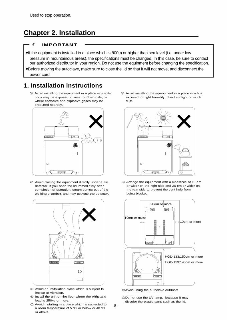
●If the equipment is installed in a place which is 800m or higher than sea level (i.e. under lowpressure in mountainous areas), the specifications must be changed. In this case, be sure to contactour authorized distributor in your region. Do not use the equipment before changing the specification.●Before moving the autoclave, make sure to close the lid so that it will not move, and disconnect the
power cord.
1. Installation instructions
IMPORTANT
20cm or more
10cm or more10cm or more
0.20.30.400.1 0.20.30.400.1
HGD-133:150cm or more
⑧Avoid using the autoclave outdoors
⑨Do not use the UV lamp, because it maydiscolor the plastic parts such as the lid.
HGD-113:140cm or more
① Avoid installing the equipment in a place where itsbody may be exposed to water or chemicals, orwhere corrosive and explosive gases may beproduced neareby.
② Avoid installing the equiopment in a place which isexposed to hight humidity, direct sunlight or muchdust.
③ Avoid placing the equipment directly under a firedetector. If you open the lid immediately aftercompletion of operation, steam comes out of theworking chamber, and may activate the detector.
④ Arrange the equipment with a clearance of 10 cmor wider on the right side and 20 cm or wider onthe rear side to prevent the vent hole frombeing blocked.
⑤ Avoid an installation place which is subject toimpact or vibration.
⑥ Install the unit on the floor where the withstandload is 250kg or more.
⑦ Avoid installing in a place which is subjected toa room temperature of 5 ℃ or below or 40 ℃or above.

- 9 -
2. Installation procedure
① Secure the main body firmly.・Install the autoclave in a place where there is no foreign matter or convex surface on the floor.
・Do not install in a place where an operation of the Electric leakage breaker located in the right side of the main body becomes difficult.
・Turn the level adjusters so that the casters are slightly lifted and the body is installed ashorizontally as possible.
② Connect the power cord to the rated power supply.
●Do not forcibly bend, twist, tie, or extend the power cord. Do not place heavy objects on the cord. A damaged cord or exposed wire may cause fire or electric shock.●Never connect the power cord to a power supply with a voltage other than the rated voltage.
Connection to such a power supply may cause fire or electric shock.●Be sure to ground the autoclave before connecting it to the power source.●Be sure to connect the grounding wire to properly installed grounding terminal. Never connect the
grounding wire to gas pipes or water pipes.
・Connect the Green/Yellow earth wires to the grounding terminal securely.・Prepare near the main body a dedicated circuit breaker or a switch and connect the autoclave to it.
CAUTION
Level adjusters
BrownBlack Grey Blue
G reen/Yellow
AC400V 3φ Power supply wires
Neutral wire{
Ea rth wire
Power co rd

- 10 -
③ Turn ON the electric leakage breaker.・Raise the lever of the electric leakage breaker located on the right side of the main body.・Identification code is displayed on the operation panel for 2 seconds.
④ Press the POWER switch on the operation panel. (refer to “1 Power supply “ ofChapter 3. Operation procedure)
⑤ Press the LID OPEN switch to open the lid and take out the supplied accessories from the chamber. (refer to “ 8. Taking out the load” of Chapter 3. Operation procedure.)
⑥ Put the bottom plate in the chamber.
To turn on, raise the leverElectric leakage breaker
ONI
Bottom plate

- 11 -
⑦ Connecting to the drain system.(1) Attach the hose to the drain outlet located in the body rear.
(2) Adjust the length of the hose according to the distance between a drain outlet and a drain pipeand cut the hose off at a length that there is no slack in the hose.
(3) Connect both ends of the hose to the drain outlet of the main body and the drain pipe.
・When draining to the drain pipe, connect the hose so as not to leak air from the drain pipe.
●Avoid connecting the hose as shown below, for water in the chamber can not be discharged.
・The position of the drain hose is higher than the drain outlet・ There is slack in the drain hose.
Drain pipe
Drain hose
IMPORTANT
Drain pipe
This position is higherthan the drain outlet.
There is slack in the hose
Drain hose
- 12 -
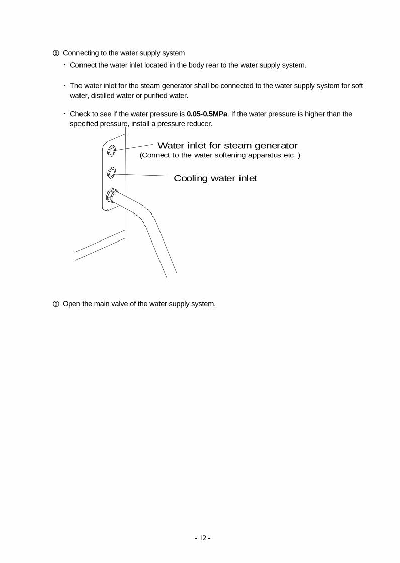
⑧ Connecting to the water supply system・Connect the water inlet located in the body rear to the water supply system.
・The water inlet for the steam generator shall be connected to the water supply system for softwater, distilled water or purified water.
・Check to see if the water pressure is 0.05-0.5MPa. If the water pressure is higher than the specified pressure, install a pressure reducer.
⑨ Open the main valve of the water supply system.
Water inlet for steam generator
Cooling water inlet
(Connect to the water softening apparatus etc. )

- 13 -
Chapter 3. Operation MethodBasic operation procedure
Turn ON the Power Supply ―――――― See "1. Power supply” on page 14.
▼Open the lid
▼ See "2. Placing the load" on page 15.Place the load
▼Check and select
the cycle See "3. Selecting the cycle and program" on page 17.
▼Check and change
the set value See "4. Changing the set value" on page 19.
▼
▼ ▼
(In the case of a reservation timer operation)
See “■Setting the reservation timer” on page 24
Start operation See "6. Starting the operation" on page 31.▼
Check if the operationhas been completed
▼Open the lid ――――― See "7. Taking out the load" on page 32.
▼Take out the load
▼Turn OFF the power supply ―――――― See "8. After completion of operation" on page 33.
Set the resvation timer

- 14 -
1. Power supply
① Press the "POWER" switch on the operation panel.
・ blinks, the set value is displayed and the autoclave becomes the standby state.
●The set values are stored in the internal memory when starting the operation. Before an operation isstarted with the changed cycle, temperature or time, if the power supply is cut off by power failure orby turning off the Electric leakage breaker, the changed values return to the previous values at the time when the power supply is turned on again. Therefore, the cycle, temperature and time set for theprevious operation are displayed.
・When the chamber temperature is higher than the lid lock temperature, or when the chamber pressureis not same as atmospheric pressure, temperature and pressure in the chamber are displayed on thedigital display window. In addition, when temperature in the steam generator is high, “ “ is displayed on the digital display window.
・When an operation switch is left untouched for 10 minutes during standby state, the equipment becomespower saving mode. Once the autoclave becomes power saving mode, the display disappears and a dot blinks on the digital temperature display window.Pressing any switches other than the LID OPEN switch during power saving mode returns the autoclave to the standby state.
ST-BY
●When the POWER switch is pressed, the autoclave becomes the stand-by state, " " is displayedon the digital display window and an electric alarm rings to inform it that the operation has not beencompleted. An event of power failure is stored and notified even if the POWER switch is pressedrepeatedly to turn the equipment on or off. When power failure is being notified, press the STOPswitch and the equipment becomes standby state (the state before starting the operation).Then, redo an operation.
W AR M C O M P
W A R M ℃
SO LID D IS S O L
1 2 3PR O G M
Alternate displaySTART
STOP
During operation, if the POWER switch is pressed and turned off, or when the power supply is interrupted due to power failure, etc.,
△ NOTE
POWER
LID
CLOSE
OPEN
LID
START
STOP
ST- BY HEAT STERIDISSOL EXHT COOL WARM COMP
TEMP ℃ TIME h:min DRY min
MPaPRESS
EXHT WATER CLEANING
SOLIDFABRIC LIQ AGARSETFUNC
ON
OFF 1 2 3PROGM
DRY
WARM ℃
COOLING
TIME
ST- BY H EAT STERIDISSOL EXHT COOL WARM CO MP
TEMP ℃ h:min min
MPaPRESS
DRY
WAR M
DRY
℃

- 15 -
2. Placing the load
① Press the "LID OPEN" switch.
・When the LID OPEN indicator lights up in redto show that the temperature or pressure withinthe chamber is high, the lid can not be opened.Wait until the LED indicator turns into green.
・The door will open automatically with the warning beep.
●Do not touch the lid or lid cover while the warning beep sounds.
② Place the material to be sterilized (or to be dissolved) in the chamber.
●When using a waste bag or the like for sterilization, place the bag in the wire basket and put it into the chamber. Putting the bag directly into the chamber clogs the piping and may causeover-temperature, over-pressure, boil-dry, etc.
●Do not contact the mouth of the container which is placed in the chamber with the inner surface ofthe lid. If the mouth of the container is closed by the lid inner surface, gas or liquid will gush out ofthe container when opening the lid.
・The lid gasket installed in the chamber opening isan important part to hold chamber pressure. Do not damage it with the load.
・Be careful not to pinch the waste bag etc. betweenthe lid and the lid gasket.
・Do not put into the chamber the material which is longerthan the inner depth of the chamber specified in the specification.
●Be sure to use the bottom plate.
CAUTION
IMPORTANT
CLOSELID
LIDOPEN
Green
IMPORTANT
- 16 -
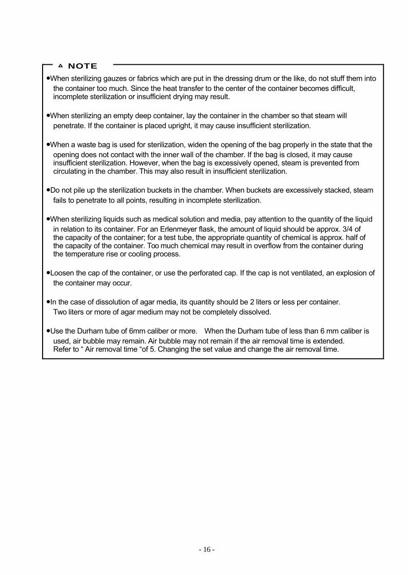
●When sterilizing gauzes or fabrics which are put in the dressing drum or the like, do not stuff them intothe container too much. Since the heat transfer to the center of the container becomes difficult,incomplete sterilization or insufficient drying may result.
●When sterilizing an empty deep container, lay the container in the chamber so that steam willpenetrate. If the container is placed upright, it may cause insufficient sterilization.
●When a waste bag is used for sterilization, widen the opening of the bag properly in the state that theopening does not contact with the inner wall of the chamber. If the bag is closed, it may causeinsufficient sterilization. However, when the bag is excessively opened, steam is prevented fromcirculating in the chamber. This may also result in insufficient sterilization.
●Do not pile up the sterilization buckets in the chamber. When buckets are excessively stacked, steamfails to penetrate to all points, resulting in incomplete sterilization.
●When sterilizing liquids such as medical solution and media, pay attention to the quantity of the liquidin relation to its container. For an Erlenmeyer flask, the amount of liquid should be approx. 3/4 ofthe capacity of the container; for a test tube, the appropriate quantity of chemical is approx. half ofthe capacity of the container. Too much chemical may result in overflow from the container duringthe temperature rise or cooling process.
●Loosen the cap of the container, or use the perforated cap. If the cap is not ventilated, an explosion ofthe container may occur.
●In the case of dissolution of agar media, its quantity should be 2 liters or less per container.Two liters or more of agar medium may not be completely dissolved.
●Use the Durham tube of 6mm caliber or more. When the Durham tube of less than 6 mm caliber isused, air bubble may remain. Air bubble may not remain if the air removal time is extended.Refer to “ Air removal time “of 5. Changing the set value and change the air removal time.
△ NOTE
- 17 -
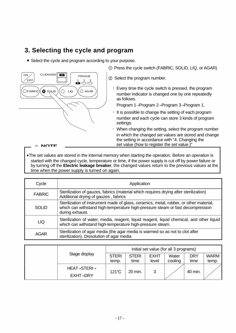
3. Selecting the cycle and program● Select the cycle and program according to your purpose.
① Press the cycle switch (FABRIC, SOLID, LIQ, or AGAR)
② Select the program number.
・Every time the cycle switch is pressed, the programnumber indicator is changed one by one repeatedlyas follows.Program 1→Program 2→Program 3→Program 1,・It is possible to change the setting of each program
number and each cycle can store 3 kinds of program settings.・When changing the setting, select the program number
in which the changed set values are stored and changethe setting in accordance with "4. Changing the set value (how to register the set value.)"
●The set values are stored in the internal memory when starting the operation. Before an operation isstarted with the changed cycle, temperature or time, if the power supply is cut off by power failure orby turning off the Electric leakage breaker, the changed values return to the previous values at the time when the power supply is turned on again.
Cycle Application
FABRIC Sterilization of gauzes, fabrics (material which requires drying after sterilization)Additional drying of gauzes , fabrics
SOLIDSterilization of instrument made of glass, ceramics, metal, rubber, or other material,which can withstand high-temperature high-pressure steam or fast decompressionduring exhaust.
LIQ Sterilization of water, media, reagent, liquid reagent, liquid chemical, and other liquid which can withstand high-temperature high-pressure steam.
AGAR Sterilization of agar media (the agar media is warmed so as not to clot aftersterilization), Dissolution of agar media
Initial set value (for all 3 programs)Stage display STERI
temp.STERItime
EXHTlevel
Water cooling
DRYtime
WARM temp.
HEAT→STERI→EXHT→DRY
121℃ 20 min. 3 40 min.
△ NOTE
CLEANING
SOLIDFABRIC LIQ AGAR
ON
OFF 1 2 3PROGM

- 18 -
FABRICcycle
Initial set value (for all 3 programs)Stage display STERI
temp.STERItime
EXHTlevel
Water cooling
DRYtime
WARMtemp.
HEAT→STERI→ EXHT→COOL 121℃ 20 min. 3 (fixed) OFF
SOLIDcycle
Initial set value (for all 3 programs)Stage display STERI
temp.STERItime
EXHTlevel
Water cooling
DRYtime
WARMtemp.
HEAT→STERI→EXHT→COOL
121℃ 20 min. 0 OFF
LIQcycle
Initial set value (for all 3 programs)AGARcycle Stage display STERI
temp.STERItime
EXHTlevel
Water cooling
DRYtime
WARMtemp.
ST- BY HEAT STERIDISSOL EXHT COOL WARM COMP
TEMP ℃ TIME h:min DRY min
MPaP RE S S
EXHT W A TE R CLEANING
SOLIDFABRIC LIQ AGARSETFUNC
ON
OFF 1 2 3PROGM
DRY
W A R M ℃
C O O LIN G
ST- BY HEAT STERIDISSOL EXHT COOL WARM COMP
TEMP ℃ TIME h:min D R Y min
MPaP RE S S
EXHT W A TE R CLEANING
SOLIDFABRIC LIQ AGARSETFUNC
ON
OFF 1 2 3PROGM
DRY
W A R M ℃
C O O LIN G
ST- BY HEAT STERIDISSOL EXHT COOL WARM COMP
TEMP ℃ TIME h:min D R Y m in
MPaP R E S S
EXHT W A TE R CLEANING
SOLIDFABRIC LIQ AGARSETFUNC
ON
OFF 1 2 3PROGM
DRY
W A R M ℃
C O O L IN G

- 19 -
HEAT→STERI→EXHT→COOL→WARM
121℃ 20 min. 0 OFF 50℃
4. Changing the set value (how to register the set value.)
●The set values are stored in the internal memory when starting the operation. Before an operation isstarted with the changed cycle, temperature or time, if the power supply is cut off by power failure orby turning the Electric leakage breaker off , the changed values return to the previously set valueswhen the power supply is turned on.
■Sterilization temperature, sterilization time, drying time, warming temperature,
When changing the set values, select the cycle of which setting is changed and the program number in which the changed set values are stored, and follow the steps below. The set values cannot be changed during operation.
① Press the "SET" switch.The display of the set sterilization (dissolution) temperature blinks and the setting change becomes possible.
② When changing the setting other than the sterilization temperature, press the "SET" switchfurther and select the setting item of which set values are changed.・Every time the switch is pressed, the alterable setting item is changed in turn.
Switch input
▽ ▽ ▽
FABRIC cycle Sterilization temperature
Sterilization time
Dryingtime
SOLID cycle Sterilization temperature
Sterilization time
LIQ cycle Sterilization temperature
Sterilization time
AGAR cycle Sterilizationtemperature
Sterilizationtime
Warmingtemperature
△ NOTE
SET SET SET
ST- BY HEAT STERIDISSOL EXHT COOL WARM COMP
TEMP ℃ TIME h:min D R Y m in
MPaP RE S S
EXHT W A TE R CLEANING
SOLIDFABRIC LIQ AGARSETFUNC
ON
OFF 1 2 3PROGM
DRY
WARM ℃
C O O LIN G
S T - B Y H E A T S T E R ID IS S O L E X H T C O O L W A R M C O M P
T E M P ℃ T I M E h :m in W A R M ℃
M P aP R E S S
E X H T F A N D R A I N
A G A RL I Q S O L ID D IS S O LS E TF U N C
B O T T L EO N
O F F 1 2 3P R O G M
- 20 -
・When performing the additional drying only, set the sterilization time in FABRIC cycle to 0.The additional drying stage is performed without sterilization stage.・When performing dissolution of agar media, set the sterilization temperature to 60-104℃.
③ Press UP/DOWN switch (▲ ▼) to change the value.・Every time the switch is pressed, the set value increases or decreases as follows;
1). Sterilization temperature: within the following range and in increments of 1℃.On FABRIC, SOLID or LIQ cycle: within the range of 105℃-135℃, On AGAR cycle:
within the range of 60℃-135℃(he temperature of 104℃ or less is for dissolution)2). Sterilization time: within the following range and in increments of 1 minute.
On FABRIC cycle: within the range of 0-5 hoursOn SOLID, LIQ or AGAR cycle: within the range of 1-5 hours.
3). Drying time: within the range of 1-99 minutes, in increments of 1minute4). Warming temperature: within the range of 45℃-60℃, in increments of 1℃
・Holding down the switch increases (decreases ) the value in increments of 10, and it returns tothe lower (upper) limit when the value exceeds the upper (lower) limit.
④ If the switch is left untouched for 5 seconds, the display will return from blinking to lighting state. Registration of the set value has been completed.
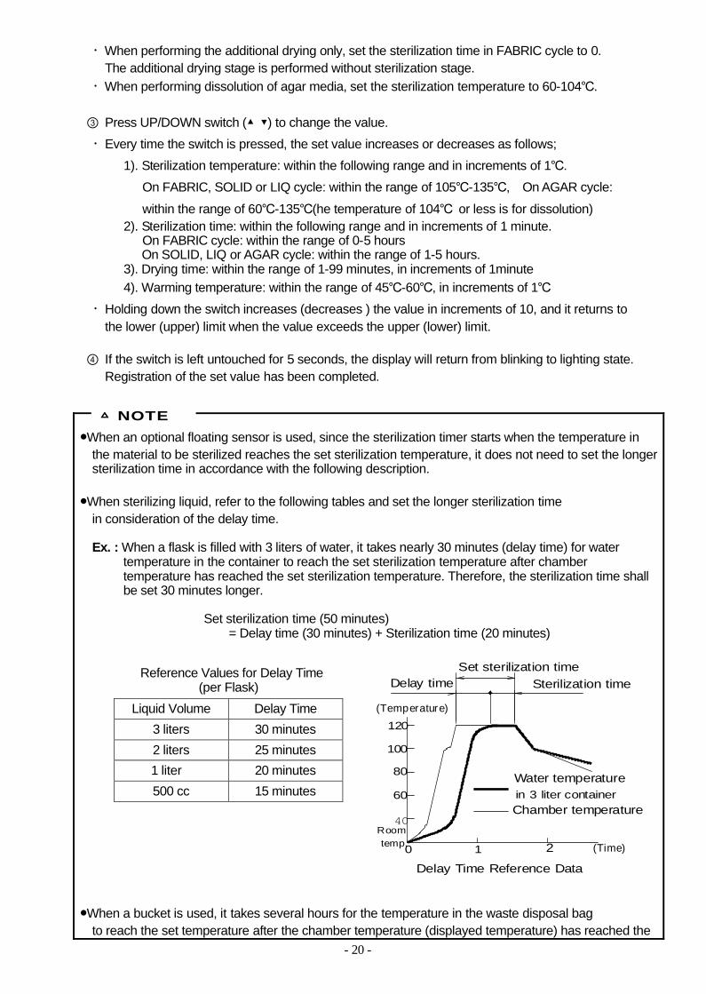
●When an optional floating sensor is used, since the sterilization timer starts when the temperature inthe material to be sterilized reaches the set sterilization temperature, it does not need to set the longersterilization time in accordance with the following description.
●When sterilizing liquid, refer to the following tables and set the longer sterilization time in consideration of the delay time.
Ex. : When a flask is filled with 3 liters of water, it takes nearly 30 minutes (delay time) for watertemperature in the container to reach the set sterilization temperature after chamber temperature has reached the set sterilization temperature. Therefore, the sterilization time shallbe set 30 minutes longer.
Set sterilization time (50 minutes) = Delay time (30 minutes) + Sterilization time (20 minutes)
Reference Values for Delay Time(per Flask)
Liquid Volume Delay Time3 liters 30 minutes2 liters 25 minutes1 liter 20 minutes500 cc 15 minutes
●When a bucket is used, it takes several hours for the temperature in the waste disposal bag to reach the set temperature after the chamber temperature (displayed temperature) has reached the
△ NOTE
4 0
60
80
100
120
1 20
(Temperature)
(Time)
Set sterilization timeDelay time Sterilization time
Water temperature
Chamber temperature
Delay Time Reference Data
in 3 liter container
temp.Room
- 21 -
set temperature (delay time). However, if there is approx. 300 ~ 500 milliliters of water in the wastedisposal bag, steam is generated in the bag and drives the air out. This will significantly reduce the delay time of a temperature rise. Refer to the table below and take this delay time into account when setting the sterilization time. In addition, the delay time will be reduced when a perforated sterilization bucket is used.
Reference Values for Delay Time in the Waste BagWater in Bag Delay time
No water 206 minutesWater is in Bag 48 minutes
Load : A large number of φ15 x 100 test tubesare placed in the waste bag.
●When dissolving the coagulated agar media, set an appropriate dissolution temperature and time, referring to the table below.
Reference Values for Dissolution Time (per Flask)Quantity of Liquid Dissolution Temperature Dissolution Time
2 liters 60 minutes1 liter 45 minutes500 cc
100℃25 minutes
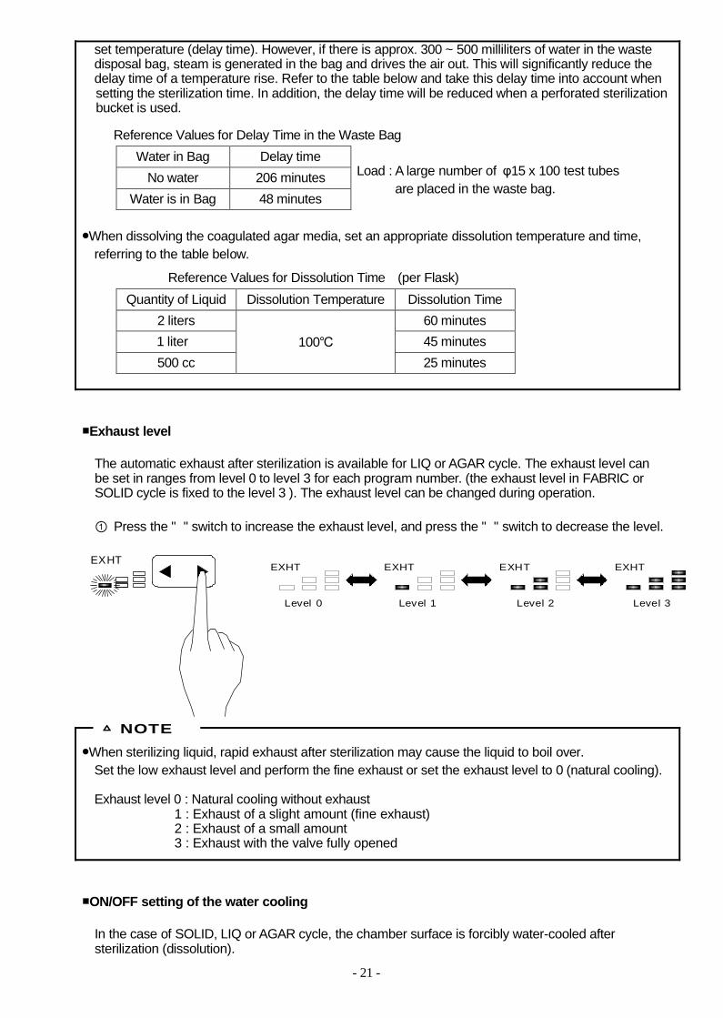
■Exhaust level
The automatic exhaust after sterilization is available for LIQ or AGAR cycle. The exhaust level canbe set in ranges from level 0 to level 3 for each program number. (the exhaust level in FABRIC orSOLID cycle is fixed to the level 3 ). The exhaust level can be changed during operation.
① Press the "" switch to increase the exhaust level, and press the "" switch to decrease the level.
●When sterilizing liquid, rapid exhaust after sterilization may cause the liquid to boil over. Set the low exhaust level and perform the fine exhaust or set the exhaust level to 0 (natural cooling).
Exhaust level 0 : Natural cooling without exhaust 1 : Exhaust of a slight amount (fine exhaust)2 : Exhaust of a small amount 3 : Exhaust with the valve fully opened
■ON/OFF setting of the water cooling
In the case of SOLID, LIQ or AGAR cycle, the chamber surface is forcibly water-cooled aftersterilization (dissolution).
△ NOTE
EXHTEXHT EXHT EXHT EXHT
Level 0 Level 1 Level 2 Level 3

- 22 -
ON/OFF of the water cooling can be set for each program number. The ON/OFF setting can bechanged during operation.
① Press the "WATER COOLING ON/OFF" switch.
・WATER COOLING indicator lights up and the chamber is cooled after sterilization (dissolution).
■Air removal time
Default setting for the air removal time in LIQ or AGAR cycle is 6 minutes from detection of 97℃. If the exhaust is often repeated during sterilization stage, or, if air bubbles remain in a Durham tube, set the air removal time a little long.
The air removal time in LIQ or AGAR cycle can be set for each program number.When changing the set values, select the cycle of which setting is changed and the program number inwhich the changed set values are stored, and follow the steps below. The set values cannot bechanged during operation.
①Press the "FUNC" switch two times during the stand-by state.
・"F2" is displayed on the digital display section, and the display of the air removal time blinks. The setting change becomes possible.
WATER ONOFFCOOLING
ST- BY HEAT STERIDISSOL EXHT COOL WARM COMP
TEMP ℃ TIME h:min DRY min
MPaPRESS
EXHT WATER CLEANING
SOLIDFABRIC LIQ AGARSETFUNC
ON
OFF 1 2 3PROGM
DRY
WARM ℃
COOLING

- 23 -
②Press UP/DOWN switch (▲,▼) to change the value.
・Every time the switch is pressed, the displayed value increases (decreases) in increments of1 minute within the range of 6-12 minutes.・When the value exceeds the upper (lower) limit, it returns to the lower (upper) limit.
③If the switch is left untouched for 5 seconds, the display returns to the stand-by state and the registration ends .
■Lid lock temperature
In the case of SOLID, LIQ or AGAR cycle, for safety purposes, the lid lock temperature whichdisables the removal of the load can be set on each program number.The default setting of the lid lock temperature is as follows.SOLID cycle : 97℃LIQ or AGAR cycle : 80℃
The set value cannot be changed during operation.
When an optional floating sensor is used, the load can not be taken out until the temperaturedetected by the floating sensor (the load temperature) drops to less than the lid lock temperature.
●It takes considerable time for the central temperature of the liquid to fall. Set the lid lock temperature in consideration of the delay of temperature drop. There is a possibility to cause burns.
①In the case of SOLID cycle, press the "FUNC" switch three times during the standby state.(In the case of LIQ or AGAR cycle, press it three times.)
・"F3" appears on the digital display section, and the set lid lock temperature blinks.The setting change becomes possible.
②Press UP/DOWN switch (▲,▼) to change the set value.
・Every time the switch is pressed, the value increases (or decreases) in increments of 1℃within the following range.SOLID cycle : 60-97℃LIQ or AGAR cycle : 60-80℃
CAUTION
ST-BY HEAT S T E R ID IS S O L EXHT COOL WA R M COMP
TEMP ℃ T I M E h:min D R Y m in
MPaP R E S S
EXHT W A T E R CLEANING
SOLIDFABRIC LIQ AGARSETFUNC
ON
OFF 1 2 3PROGM
D R Y
W A R M ℃
C O O L IN G

- 24 -
・Holding down the switch increases (decreases) the value in increments of 10℃.When the value exceeds the upper (lower) limit, it returns to the lower (upper) limit.
③If the switch is left untouched for 5 seconds, the display returns to the stand-by state and the registration ends.
■Setting the reservation timer
Once the reservation timer is set, the equipment becomes the stand-by state until the set time comes. The operation stage advances when the set time has come. The settable range of the timer is until 23:59 6-day later from the current time.
●Before setting the reservation timer, check that the clock time is correct .●The set reservation time is effective only for one operation. When operation is completed or stopped,
the set time is reset and becomes 0 day 0 hour 0 minute.
①Press the "FUNC" switch one time during the standby state.
・"F1" is displayed on the digital display section, and the reservation time is displayed.・If the switch is left untouched for 5 seconds, the display returns to the standby state.
②Press the "SET" switch
・"DAY" display blinks and the setting for the number of days becomes possible.・When the SET switch is pressed further, the change of HOUR and MINUTE becomes possible in
sequence.・If the switch is left untouched for 15 seconds during the change of setting, the set reservation time
is cancelled and the display returns to the stand-by state.
△ NOTE
S T- B Y H E A T STERIDISSOL E X H T C O O L WARM C O M P
T E M P ℃ T IM E h :m in DRY min
M P aPRESS
E X H T WATER C L E A N IN G
S O L IDF A BR IC L IQ A G ARS E TF U N C
O N
O F F 1 2 3P R O G M
DRY
WARM ℃
COOLING
ST- BY HEAT STERIDISSOL EXHT COOL WARM COMP
TEMP ℃ TIME h:min DRY min
MPaPRESS
EXHT WATER CLEANING
SOLIDFABRIC LIQ AGARSETFUNC
ON
OFF 1 2 3PROGM
DRY
WARM ℃
COOLING

- 25 -
③Change the set value with UP/DOWN switch (▲,▼) while the item to be set is blinking.
・Every time the switch is pressed, the displayed value increases (decreases) as follows.
DAY : within the range of 0-6, in increments of 1 dayHOUR : within the range of 0-23, in increments of 1 hourMINUTE : within the range of 0-59, in increments of 1 minute
・Holding down the switch increases (decreases) the value in increments of 10-unit.When the displayed value exceeds the upper (lower) limit, it returns to the lower (upper) limit.(except DAY setting)
・If the switch is left untouched for 15 seconds during the change of setting, the set reservation timeis cancelled and the display returns to the stand-by state.
●When the SET switch is pressed further in the state where the change of MINUTE setting is possible, the display returns to the stand-by state and the set time of the reservation timer is registered.
When an operation is started with the START switch, the autoclave becomes the stand-by state untilthe set time comes.
●When confirming the set time while the reservation timer is operating, press the "FUNC" switch.The set time is displayed for 5 seconds. When you need to change the set time, stop theoperation with the STOP switch and resume the operation after changing the set time.
■Check and correction of the clock function
Check if time of the clock function is correct before setting the reservation time.
①Press the FUNC switch a few times in stand-by state to display “ ” on the digital displaywindow. (the number of times to press the FUNC switch is different depending on the selectedcycle or the attached option.)
・The current time is displayed on the digital display window.
How to confirm the reservation time while the reservation timer is operating.
ST- BY HEAT STERIDISSOL EXHT COOL WAR M COMP
TEMP ℃ TIME h:min D R Y m in
MPaP R E S S
EXHT W A T E R CLEANING
SOLIDFABRIC LIQ AGARSETFUNC
ON
OFF 1 2 3PROGM
DRY
W A R M ℃
C O O L IN G
ST- BY HEAT STERIDISSOL EXHT COOL WARM COMP
TEMP ℃ TIME h:min DRY min
MPaPRESS
EXHT WATER CLEANING
SOLIDFABRIC LIQ AGARSETFUNC
ON
OFF 1 2 3PROGM
DRY
WARM ℃
COOLING
It indicates 17:08on March 27.

- 26 -
・When time is correct, leave as it is. The display returns to the stand-by state after 5 seconds.When time is incorrect, proceed to the next ② and correct the time.
②Press the SET switch while the current time is displayed.
・" " is displayed and the calendar year data blinks. Correction of the YEAR becomespossible.
・When the SET switch is pressed further, correction of MONTH, DAY, HOUR or MINUTEbecomes possible in sequence.
・If the switch is left untouched for 15 seconds in the state where the time correction is possible, the corrected time is cancelled and the display returns to the stand-by state.
③Change the set value with UP/DOWN switch (▲,▼) while the item to be set is blinking.
・Every time the switch is pressed, the displayed value increases (or decreases) as follows.
YEAR. : within the range of 2000-2099, in increments of 1 year MONTH : within the range of 1-12, in increments of 1 monthDAY : within the range of 1-31, in increments of 1 dayHOUR : within the range of 0-23, in increments of 1 hourMINUTE : within the range of 0-59, in increments of 1 minute
・Holding down the switch increases (decreases) the value in increments of the 10 units.When the displayed value exceeds the upper (lower) limit, it returns to the lower (upper) limit.
・If the switch is left untouched for 15 seconds in the state where the time correction is possible, the corrected time is cancelled and the display returns to the stand-by state.
ST- BY HEAT STERIDISSOL EXHT COOL WARM COMP
TEMP ℃ TIME h:min DRY min
MPaPRESS
EXHT WATER CLEANING
SOLIDFABRIC LIQ AGARSETFUNC
ON
OFF 1 2 3PROGM
DRY
WARM ℃
COOLING

- 27 -
ST-BY HEAT S TE RIDISS OL EXHT COOL WARM COMP
TEMP ℃ TIME h:min W A R M ℃
MPaP R E S S
EXHT FAN DRAIN
AGARLIQ SOLID DISSOLSETFUNC
BOTTLEON
OFF 1 2 3PROGM
●When the SET switch is pressed further in the state where the MINUTE correction is possible, the display returns to the stand-by state and the corrected time is registered.
■Preheating
The total cycle time is reduced by heating the chamber before starting the operation. If the preheating is set to ON, the autoclave heats the chamber up to a certain temperature level when turning on the power supply. However, the power saving mode in stand-by state does not operate.
①Press the FUNC switch a few times in stand-by state to display “ “ on the digital displaywindow. (the number of times to press the FUNC switch is different depending on the selectedcycle or the attached option.)
・The setting of ON or OFF displayed on the digital display window is blinking, allowing the change of the setting.
②Change the set value by pressing UP/DOWN switch (▲,▼)
・Every time the switch while the item to be set is blinking. is pressed, display of ON or OFF changes alternately.
③If the key is left untouched for 5 seconds, the display returns to the stand-by state and the setting ends .
ST- BY HEAT S T E R ID IS S O L EXHT COOL W A R M COMP
TEMP ℃ T I M E h:min D R Y m in
MPaP R E S S
EXHT W A T E R CLEANING
SOLIDFABRIC LIQ AGARSETFUNC
ON
OFF 1 2 3PROGM
D R Y
W A R M ℃
C O O L IN G

- 28 -
5. Recording function
●The temperature and pressure in the chambercan be recorded with the PC or the USB flash memory.
■Connecting to the PC
・Connect the PC connector of the autoclave to a USB connector of the PC with USB cableduring the standby state.
・When the autoclave is connected with the PC, the driver is automatically installed in the PC and a USB serial port (COM) is added to the device manager. If the driver can not be installed automatically, install VCP driver by downloading it from the website of FTDI(http://www.ftdichip.com/Drivers/VCP.htm)
The USB Serial Port (COM)that was added to the PC devicemanager.
・Change the setting of PC communication port as follows.Port : COM number that was added, Baud rate : 9600, Data bits : 8 bits, Parity : even numberStop bits : 1 bit, Flow control : OFF
・When an operation starts, such data as shown in the next page is output. The temperature and pressure in the chamber are recorded every second. When the operation advances to the warmingstage, when the operation ends or stops or when an error occurs, output of the data stops.
・When importing the recorded data into Excel spreadsheets, choose " ○Delimited -Characters such as commas or tabs separate each field " from Original data type in the Text Import Wizard - Step 1 of 3.In the second step, choose " □Space " from Delimiters in the Text Import Wizard - Step 2 of 3, then,import the data.
USB connector
For flash memory For PC
at right side of the main body

- 29 -
■Connecting the USB flash memory to the autoclave. ・Connect the USB flash memory which was formatted to FAT32 to the USB connector of the autoclave
during the standby state.
・When an operation starts, such data as shown below is saved into the flash memory as the name of "HMC_(Cycle number).LOG". The temperature and pressure in the chamber are recorded every second. When the operation advances to the warming stage or when the operation ends or stops the data is saved.
・Remove the flash memory when autoclave is in the standby or the completion state. Do not removethe flash memory during operation, for the data may be broken.
・The recorded data is a text file. When importing the recorded data into Excel spreadsheets, choose" ○Delimited -Characters such as commas or tabs separate each field " from Original data type in the Text Import Wizard - Step 1 of 3. In the second step, choose " □Space " from Delimiters in the Text Import Wizard - Step 2 of 3, then, import the data.
●If the access indicator for the flash memory does not blink during operation, the data is not beingrecorded. Turn off the "Electric leakage breaker" and start an operation again. If the access indicator does not blink yet, please contact our authorized distributor in your region.
■The record and output format
△ NOTE

- 30 -
Manufacturer HMCDevice Name HICLAVEModel. HGD-113Version Number. 1.0Cycle Count. 0001Date. 23 Apr 2010Program. FABRIC1Sterilization Temperature 121℃Sterilization Time 00:20Drying time 40
15:30:32 28.0 28.0 0.000 Heating15:30:33 28.0 28.0 0.000 Heating::15:55:25 121.5 121.0 0.106 Steri.15:55:26 121.5 121.5 0.106 Steri.::16:15:26 121.3 121.4 0.105 Exhaust16:15:27 121.2 121.4 0.105 Exhaust::Status = SuccessStatus = CanceledError ○
Manufacturer
Device name
Model
Software version number
Cycle identification number(Total number of operations) Date of cycle start
Selected cycle
Set sterilization temperature
Set sterilization temperature
Set drying time
Current time, Control sensor temperature, Floating sensortemperature (When not used, display shows 000.0)Chamber pressure, Stage
Completion of operation ( proceed to warming stage)
Stop of operation
Error occurred
6. Starting the operation①Press the START switch.
・The lid is closed automatically with the warning beep. "ST-BY" goes outand the following stages are automatically performed according to theselected cycle. Refer to "11. Operation of each stage" on page 34 for detailed operation of each stage.
・An operation does not start except when the lid is fully open or completelyclosed. Press the LID OPEN switch to open the lid completely, then pressthe START switch.
● Be careful not to pinch your hand when closing the lid.● Do not touch the lid or lid cover while the warning beep sounds.● Start an operation after confirming that there is no foreign matter on the contacting surface of the
chamber where the lid gasket is installed. It may cause steam leaks.
●If the lid is closed when the chamber temperature is high, the sound that air in the chambercomes out through the gasket can be heard. Continue operation, for it is not failure.
Operation stages of each cycle
CAUTION
START
STOP
△ NOTE

- 31 -
・If the sterilization time in FABRIC cycle is set to 0, a drying stage is executed after closing the lid.・If the sterilization temperature is set to 60-104℃, a sterilization stage is switched to a dissolution stage.
●When confirming the set temperature or time during operation, press the SET switch.The set value is displayed while holding down the switch. But, the value can not be changed with any switch.
7. Taking out the load
●When the cycle was completed, or when the sterilization stage in AGAR cycle was completed and thechamber temperature became lower than the lid lock temperature or the chamber pressure droppedto 0MPa, the lid can be opened.
●When a salt solution or a high-salt liquid such as salt agar spillsin the chamber, discharge water in the chamber and wipe updrops of water around the lid gasket. If such state is leftuntouched, It causes corrosion of the chamber and pipingand leads to an explosion accident.
●Open the lid after confirming that the chamber pressure has dropped to 0MPa.
How to confirm the setting during operation.
FABRIC cycle SOLID cycle LIQ cycle AGAR cycle
Closing the lid
Starting the reservation timer
Vacuum air removal
Heating
Sterilization
Drainage
Gravity air displacement
Cooling
Exhaust / Cooling
Warming
Completion
WARNING
CAUTION
Exhaust
Cooling
Drying
Compound Gauge
0.20. 1
0.3
0.4-0.1
00

- 32 -
●Do not bring your face or hands close to the chamber when you open the lid shortly after the end of operation, because hot air may gush out of the chamber opening.
●The lid, chamber, gasket, etc, becomes very hot after an operation ends. Do not touch them, oryou may get burned.
●It takes considerable time for liquid to be cooled down. Therefore, before taking out the sterilizedliquid from the chamber, be sure to check that temperature has dropped sufficiently, or you mayget burned.
●If the liquid surface which is placed in the chamber is covered with oil, etc, the liquid may gush outwhen taking out or carrying. Be sure to check that the liquid temperature has dropped sufficientlybefore taking out the liquid from the chamber, or it may cause burns.
●Put on the heat-resistant gloves for preventing burns and take out the load after hot air in the chamberhas been discharged.
①Press the LID OPEN switch.
・The lid is automatically opened with the warning beep.・When the temperature or pressure in the chamber is high
and the LID OPEN indicator lights up in red, the lid cannot be opened. Wait until it turns into green.
②Taking out the load.
③Press the LID CLOSE switch.
・When the chamber temperature is high, you may hearthe sound that air in the chamber comes out of the gasket. Continue operation, for it is not failure.
・The lid cannot be closed in the state where the lid isnot completely open. Press the LID OPEN switch tofully open the lid, then, press the LID CLOSE switch.
8. After completion of operation①At the end of operation of the day, press the POWER switch to turn off power.
●The cycle, set temperature or set time for the previous operationis stored in the memory even after power failure or the Electric leakage breaker switch is turned off.
△ NOTE
CL O S ELID
L IDOP E N
Green
POWER
LID
CLOSE
OPEN
LID
START
STOP

- 33 -
9. How to interrupt the operation
10. When the power supply is interrupted during a cycle● When the power supply is cut off due to a power failure or the like, the cycle is interrupted.
When the POWER switch is pressed again the equipment becomes stand-by state, “ ” isdisplayed on the digital display window and an electric alarm sounds indicating that the cycle wasnot completed due to a power failure. The power failure notice is saved and the notice is indicated even if ON/OFF of the POWER switch isrepeatedly switched. When the power failure notice is displayed, pressing the STOP switch turns thedisplay into the ST-BY state. (the state before starting an operation). Redo an operation.When the POWER switch is pressed to turn off the power during a cycle, the same power failure notice is displayed.
11. The operation of each stage
Display of a stage
■A process to close the lid…… Common to all cycles
・The temperature and pressure in the chamber are displayed on the digital display window.
①Press the STOP switch.
・The automatic operation is interrupted and the equipment returns to the stand-by state (the state before starting an operation). If the chamber temperature is higher than the lid lock temperature or the chamber pressure is not atmospheric pressure, the temperature and pressure in the chamber are displayed. When the temperature in the steam generator is high, “ ” is displayed on the digital display window.
・If the operation is interrupted while the vacuum pump is running, thevacuum pump continues to operate until the motor valve is closed.
・When taking out the load, refer to "7. Taking out the load" on theprevious page. The lid can not be opened unless the chambertemperature becomes lower than the lid lock temperature or thechamber pressure falls to 0MPa.
STOP
WARM COMP
WARM ℃
SOLID DISSOL
1 2 3PROGM
Alternate displaySTART
STOP
ST-BY HEAT STERIDISSOL EXHT COOL DRY COMPWARM

- 34 -
・The lid is closed with the warning beep.
■A process to operate the reservation timer …… Common to all cycles (When the reservation timer is set.)
・A LED segment in the digital display window lights up sequentially in a loop state untilthe set reservation time comes.
・When confirming the set time, press the FUNC switch.The set time is displayed for 5 seconds.
■Vacuum air removal process …… FABRIC, and SOLID cycle
・ in the stage display turns into blinking from lighting state.
・After air in the chamber is drawn by a vacuum pump, water is automatically supplied to the steamgenerator and the heater is turned on to generate steam.
・When the chamber pressure becomes atmospheric pressure or more, vacuum air removal is carried out again.
■Gravity air displacement process …… LIQ, and AGAR cycle
・ in the stage display turns into blinking from lighting state.
・Water is automatically supplied to the steam generator and the heater is turned on to generate steam.
・Air purge by steam is carried out until the set air removal time passes after the chamber temperaturereaches 97℃.
■Heating stage …… Common to all cycles
・The exhaust valve is closed and temperature rises until it reaches to the set sterilization temperature(pressure).
■Sterilization stage …… Common to all cycles
・ in the stage display turns into blinking from lighting state, and the set sterilization time is displayed on the digital display window simultaneously with start of the sterilization timer.
・The temperature (pressure) is kept constant during period of the set sterilization time.
・When the chamber temperature drops 0.1℃ or more from the set value due to a trouble, the overcoolmark on the digital display lights up, and the sterilization timer stops. When the set temperature is regained, the timer restarts operation.
A L E D l i g h t s u p i n a l o o p s t a t e
HEAT
STERIDISSOL
HEAT
Overcool mark
℃ TIME h:min.
Blinking stops
TEMP

- 35 -
・The digital timer indicates the remaining time during the sterilization stage. When confirming the settime, press the SET switch. While the switch is being pressed, the set value is displayed. However, theset value cannot be changed.
●In sterilization of petri dishes or empty containers, the air remaining in the container expands and
the pressure within the chamber may become higher than usual. If the pressure in the chamberexceeds the saturated steam pressure, the exhaust valve opens and discharges the residual air inthe chamber.
●The chamber temperature is a little high so that it will not become lower than the set
sterilization temperature.
■Dissolution stage …… AGAR cycle (when the sterilization temperature is set to 60-104℃.)
・ in the stage display turns into blinking from lighting state, and the set dissolution time is displayed on the digital display window simultaneously with start of the dissolution timer.
・The digital timer indicates the remaining time during the dissolution stage. When confirming the settime, press the SET switch. While the switch is being pressed, the set value is displayed. However, theset value cannot be changed.
■Exhaust stage …… FABRIC cycle
・ in the stage display turns into blinking from lighting state, and the chamber pressure is displayed on the digital display window.
・The exhaust valve is opened and steam in the chamber is discharged rapidly.■Exhaust / Cooling stage …… SOLID, LIQ, and AGAR cycle
・ in the stage display turns into blinking from lighting state, and the chamber pressure is displayed on the digital display window.
・On SOLID cycleThe exhaust valve is opened and steam in the chamber is discharged rapidly. In addition, when thewater cooling function is set to ON, the cooling valve is opened and outside of the chamber is cooledwith water. The ON/OFF setting change of the water cooling function is possible during theexhaust/cooling stage.
・On LIQ or AGAR cycleWhen the exhaust level is set to 1 or 2, the exhaust solenoid valve is opened rhythmically to dischargesteam in the chamber finely. When the exhaust level is set to 0, the exhaust solenoid valve is not opened and the load is cooled naturally. When the exhaust level is set to 3, the exhaust solenoidvalve is opened to discharge steam in the chamber rapidly.In addition, when the water cooling function is set to ON, the cooling valve is opened and outside of the chamber is cooled with water. The ON/OFF setting change of the water cooling function ispossible during the exhaust/cooling stage.
△ NOTE
STERIDISSOL
EXH T
EXHT

- 36 -
●When sterilizing liquid, rapid exhaust after sterilization may cause the liquid to boil over. Set the low exhaust level and perform the fine exhaust or set the exhaust level to 0 (natural cooling).
Exhaust level 0 : Natural cooling without exhaust 1 : Pulse exhaust (Exhaust of a slight amount)2 : Pulse exhaust (Exhaust of a small amount)3 : Exhaust (Rapid exhaust)
■Drainage stage …… FABRIC, and SOLID cycle
The drain valve is opened and water in the steam generator is discharged.
■Cooling stage …… SOLID, LIQ, and AGAR cycle
・ in the stage display turns into blinking from lighting state.
・The exhaust valve is fully opened. When the water cooling function is set to ON, the cooling valve isopened and outside of the chamber is cooled with water. The ON/OFF setting change of the watercooling function is possible during the exhaust/cooling stage.
・In the case of AGAR cycle, the lid can be opened or closed when the chamber temperature dropsbelow the lid lock temperature.
■Drying stage …… FABRIC cycle
・ in the stage display turns into blinking from lighting state. The set drying time is digitally
displayed at the same time that the drying timer begins to operate. "---" is displayed on thetemperature display window.
・The digital timer indicates the remaining time. When confirming the set time, press the SET switch.While the switch is being pressed, the set value is displayed. However, the set value cannot bechanged.
・The heater is turned on to vaporize moisture. Steam in the chamber is drawn by a vacuum pump. And when the chamber pressure drops to the certain level, the filtered air is supplied to the chamber.Air sucking and air supply are alternately repeated during the set dry time.
■Warming stage …… AGAR cycle
・ in the stage display turns into blinking from lighting state, and remaining time of warming timer is digitally displayed .
・Start of the warming stage is notified with a bleep.
・The warming timer is fixed to 24hours.
△ NOTE
COOL
WARMDRY
WARMDRY

- 37 -
● After the warming time is over (after 24 hr), the chamber is not heated anymore. The chambertemperature drops to the room temperature, and the agar media, etc. is clotted.
● When taking out the load during warming stage, refer to "7. Taking out the load" on page 32.
■Completion …… Common to all cycles
・When all stages of a cycle have been completed, a beep rings three times and in the stage display blinks indicating that all stages have been completed.
・If any switch is left untouched for 10 minutes, the power saving mode is activated. The display disappears and a dot blinks on the temperature digital display window. Pressing any switches exceptthe LID OPEN switch returns to the completion state.
Chapter 4. Maintenance and Service● For safe use of the autoclave, inspect the parts once for every period not exceeding one year according
to the maintenance and service procedure.
1. Cleaning the steam generator●When the "CLEANIG" indicator lights up in red, execute cleaning to remove scale that accumulates
inside the steam generator.
①Press the FUNC switch a few times in stand-by state to display "" on the digital displaywindow. (the number of times to press the FUNC switch is different depending on the selectedcycle or the attached option.)
・Leaving it untouched for 5 secondsreturns the display to stand-by state.
△ NOTE
COMP
TI ME
ST-BY HEAT STERIDISSOL EXHT COOL WARM COMP
TEMP ℃ h:min min
MPaP RE SS
DRY
WA R M
D R Y
℃
ST- BY HEAT S TE R ID IS S O L EXHT COOL WA R M COMP
TEMP ℃ T I M E h:min D R Y m in
MPaP R E S S
EXHT W A T E R CLEANING
SOLIDFABRIC LIQ AGARSETFUNC
ON
OFF 1 2 3PROGM
D RY
W A R M ℃
C O O L IN G
- 38 -
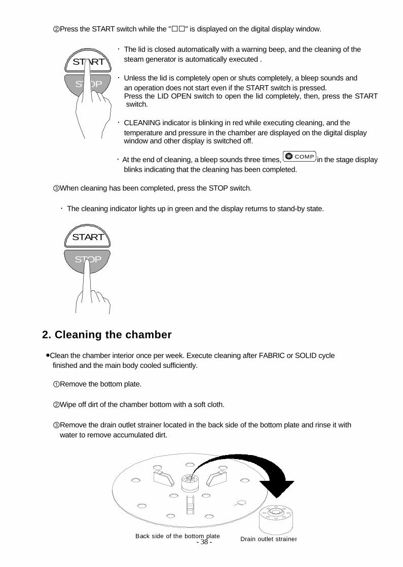
②Press the START switch while the "" is displayed on the digital display window.
・The lid is closed automatically with a warning beep, and the cleaning of thesteam generator is automatically executed .
・Unless the lid is completely open or shuts completely, a bleep sounds and an operation does not start even if the START switch is pressed.Press the LID OPEN switch to open the lid completely, then, press the START switch.
・CLEANING indicator is blinking in red while executing cleaning, and thetemperature and pressure in the chamber are displayed on the digital displaywindow and other display is switched off.
・At the end of cleaning, a bleep sounds three times, in the stage displayblinks indicating that the cleaning has been completed.
③When cleaning has been completed, press the STOP switch.
・The cleaning indicator lights up in green and the display returns to stand-by state.
2. Cleaning the chamber
●Clean the chamber interior once per week. Execute cleaning after FABRIC or SOLID cyclefinished and the main body cooled sufficiently.
①Remove the bottom plate.
②Wipe off dirt of the chamber bottom with a soft cloth.
③Remove the drain outlet strainer located in the back side of the bottom plate and rinse it withwater to remove accumulated dirt.
START
STOP
START
STOP
COMP
Drain outlet strainerBack side of the bottom plate
- 39 -
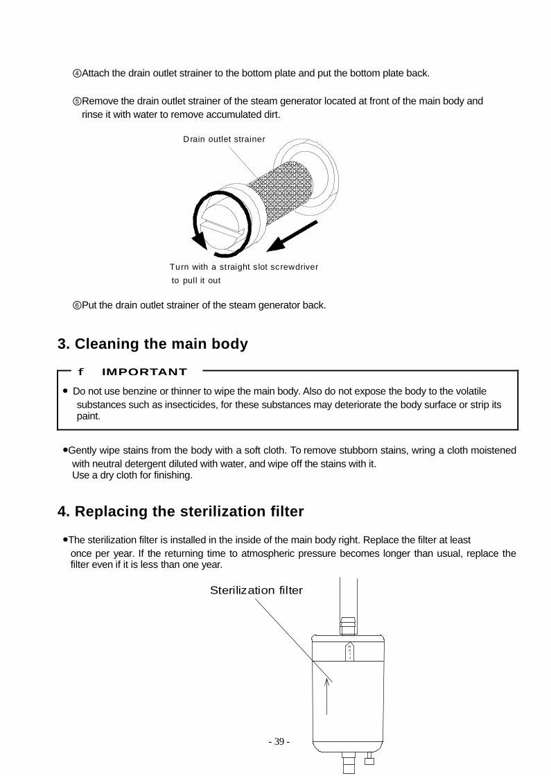
④Attach the drain outlet strainer to the bottom plate and put the bottom plate back.
⑤Remove the drain outlet strainer of the steam generator located at front of the main body andrinse it with water to remove accumulated dirt.
⑥Put the drain outlet strainer of the steam generator back.
3. Cleaning the main body
● Do not use benzine or thinner to wipe the main body. Also do not expose the body to the volatilesubstances such as insecticides, for these substances may deteriorate the body surface or strip itspaint.
●Gently wipe stains from the body with a soft cloth. To remove stubborn stains, wring a cloth moistened with neutral detergent diluted with water, and wipe off the stains with it.Use a dry cloth for finishing.
4. Replacing the sterilization filter
●The sterilization filter is installed in the inside of the main body right. Replace the filter at leastonce per year. If the returning time to atmospheric pressure becomes longer than usual, replace the filter even if it is less than one year.
IMPORTANT
Drain outlet strainer
Turn with a straight s lot screwdriverto pull it out
FLOW
Sterilization filter

- 40 -
Chapter 5. Specifications
Model HGD-113 HGD-133
Outside dimension W686 ° H930 ° D870 mm W686 ° H1034 ° D870 mm
Inside dimension Φ500 ° D576m(Effective volume: 113 liters)
Φ500 ° D680m(Effective volume: 133 liters)
Rated power supply AC400 V ²10%, Φ3, 50/60 Hz, 11 A or more
Environmental condition
Ambient temperature: 5-35℃. Relative humidity: 85%RH or less(Dew condensation not allowed.). Range of altitude: 0-2000 m
(change of specification is required when using at altitude of 801m or more.)Indoor use only. Overvoltage Category Ⅱ. Pollution Degree 2
Power consumption 7.1 kW
Net weight 184 kg 192 kg
Chamber material Stainless steel (SUS304)
Sterilization temperaturesetting range 105-135℃, variable
Sterilization timer 1-300 min. (5 hours), Remaining time is displayed
Dissolution temperaturesetting range 60-104℃, variable
Dissolution timer 1-300 min. (5 hours), Remaining time is displayed
Warming temperaturesetting range 45-60℃, variable
Drying timer 1-99 min. Remaining time is displayed
Exhaust level 4 steps, variable
Water cooling ON/OFF
Air removal time 6-12 minutes, variable
Lid lock temperatureLIQ, AGAR cycle: 60-80℃, variable
SOLID cycle: 60-97℃, variable
Reservation timer range 1minutes - 1week, Time setting method
Max. working pressure 0.25MPa
Thermometer Digital display: 5.0-137.9℃
Compound gauge Digital display: -0.1~0.3 MPa, Analog display: -0.1~0.4 MPa
Safety devices andwarning devices
Pressure safety valve, Over current breaker, Overheat prevention device for a steam generator,Error display; Steam generator overheat, Temperature sensor disconnection, Over-cool, Over-temperature, Abnormality in pressure, in the lid, in the vacuum motor valve or in the heater
Supplied AccessoriesWire Basket(2 pcs)Bottom plate(1 pc)
Operation Manual(1 copy)

- 41 -
Chapter 6. Troubleshooting1. Error detection (alarms)● When an abnormality occurs in the autoclave, the error detection circuit is actuated. The heater
circuit is turned off, the error message appears on the digital display window. In addition, an electricalarm sounds, indicating the problem. To stop the alarm sound, press the STOP switch. If an alarm isgenerated, check the error number and turn off the Electric leakage breaker.
Error display Possible cause Corrective action
Er 10~12(Overheat)
・The temperature in the heat generator is unusually high.
・Contact our authorized distributor inyour region.
・The chamber temperature has dropped below the freezing point.
・Adjust the room temperature of theinstallation place to 5-35℃.
Er 20~32
(Temperature sensor wire disconnection) ・Disconnection of the
temperature sensor wireEr 30~32(Over-temperature)
・The chamber temperature is abnormally high.
Er 40(Over-cool)
・The chamber temperature is abnormally low.・The chamber pressure is
abnormally high.
・Contact our authorized distributor in your region.
Er 50,51(Pressure abnormality)
・Piping is clogged by a wastebag or the like.
・When a waste bag or the like is used, place it in the chamber withthe bag put in the wire mesh basket
Er 60~65(Abnormality in the lid)
・There is an abnormality in thelid closing mechanism.
・Check if any foreign substance is caughtbetween the lid and the lid gasket.
Er 70.71
(Abnormality in thevacuum break motor valve)
・There is an abnormality in the vacuum break motor valve.
・Contact our authorized distributor in your region.
Er 80
(Abnormality in theWater supply system)
・The steam generator is notfilled with water even after a long time has passed.
・Check if the main valve of the watersupply system is opened.
Er 90
(Abnormality in theheater)
・The temperature does not reach to the set sterilization temperature even after a long time has passed.
・Reduce the quantity of the materials to be sterilized and redo operation from the beginning.
Erl(Abnormality in the lid lock mechanism)
・There is an abnormality in thelid lock mechanism.
erP
(Abnormality in the vacuum system)
・The chamber does not becomea vacuum during the vacuumair removal process.
・Contact our authorized distributor in your region.
er□(Power failure)
・Power supply was interruptedduring operation.
・Press the STOP switch and redo the operation from the beginning.
●When turning on a power supply, the following error detection is performed.Error display Possible cause Corrective action
erb
(fall of battery voltage)・The battery voltage has fallen.
(The clock stops)
・The battery voltage has fallenand the clock has stopped.
・it is necessary to replace the clockbattery. Please contact our authorizeddistributor in your region.

- 42 -
2.Early troubleshootingProblem Possible cause Corrective action
Display panel is not lit though power is turnedON.
①The power plug is not properlyinserted or the power supplyterminal is insufficiently fastened.②Disconnection of the power cord.③Display panel is faulty.
④Electric leakage breaker is in the OFF state.
①Properly insert the plug andretighten any loose parts.②③Contact our authorized distributor
in your region.④Turn on electric leakage breaker
No air is discharged fromthe chamber.
①Clogging of the drain outlet strainer.
②Exhaust valve is faulty.③The vacuum pump is faulty
①Refer to "Cleaning the chamber” of4. Maintenance and Service" andclean the drain outlet strainer.②Contact our authorized distributor in
your region.Pressure does not rise. ①Safety valve is faulty.
②Compound gauge is faulty.③Disconnection in the heater circuit.
④Exhaust valve is faulty⑤Steam leakage.
①-④Replace the defective partsContact our authorized distributor⑤Contact our authorized distributor in
your region.
Steam leakage fromthe lid gasket
①Deterioration of the lid gasket.②Installation of the lid gasket is
Defective.③Foreign material is caught on a gasket.
①②Contact our authorized distributorin your region.
③ Remove the foreign material.
The lid cannot beopened
①The LID OPEN indicator is lit in red.②The power supply is not turned on.
①Wait until the LID OPEN indicatorturns into green②Press the POWER switch to turn on
power.The lid can not beclosed
①The lid is not opened fully. ①Open the lid fully with the LID OPENswitch and press the LID CLOSEswitch.
Displayed temperatureexceeds the settemperature and theexhaust is repeatedfrequently during thesterilization stage.
①The heater circuit is faulty. ①Contact our authorized distributor inyour region.
The sound is bigger thanusual during vacuum airremoval stage and thedrying stage
①The drain piping is not proper. ①Rework the drain piping.
Dryness is not good. ①Drying time is short.②The load is stuffed too much.③Clogging of the drain outlet strainer
for a steam generator.④Clogging of the sterilization filter.⑤Disconnection of the heater circuit.
①Set the longer drying time.②Reduce the quantity of the load③Refer to "Cleaning the chamber” of
4. Maintenance and Service" andclean the drain outlet strainer.④⑤Contact our authorized distributor
in your region.

- 43 -
The returning time toatmospheric pressureafter drying stage is slow
①Clogging of the sterilization filter ①Contact our authorized distributor inyour region.
●This table of early troubleshooting describes the causes and remedies of simple problems. If you areunable to fix or repair the problem, contact our authorized distributor in your region and provide thefollowing information.
(1) Model and serial number of the autoclave.(2) The fault parts and condition (the error number, if the error was detected).(3) Number of days of operation (or date of purchase).(4) Operating conditions (information on the kind of materials to be sterilized).
When the total number of operation reached the designed nominal number of times, “CH” is displayed in the digital display during operation.As it is close to the lifetime of the pressure vessel, contact your authorized distributor in your region.Therefore, after the total number of operation reached the designed nominal number of times, the autoclave can not start.

- 44 -
Appendix1. Limited warranty
●The autoclave is warranted for any trouble that might occur during normal usage for one (1) year from the date of delivery to the user, but not exceeding eighteen (18) months from the date of B/L or AWBfrom Japan. This warranty does not apply to the troubles caused by any of the items described below:
(1) Any force majeure such as a fire, earthquake, or other natural disasters.(2) Disassembly, retrofit, or repair by someone other than us (or our authorized distributors).(3) Incorrect usage.
●In the case of trouble, please contact our authorized distributor in your region. In this case, be sure to tell them the name, model and serial number of the product and details of trouble.
●Supply period for spare parts (with charge) for this product shall be seven (7) years after thediscontinuance of sales.
●It is recommended to sign a maintenance contract to use the product in the best condition. If you have any questions regarding the maintenance contract, please contact our authorized distributor in your region.
2. Periodic replaced parts
●It is recommended to replace the following parts periodically to use the autoclave in the best condition.
Part names Time interval (approx.)
Lid gasket 3 years
Safety valve 10 years
Earth leakage breaker 10 years
Silicon tube 3 yearsOverheat prevention device for a steam generator 5 years
Drain outlet strainer 5 years
Sterilization filter 1 year
Clock battery (CR2032) 5 years
●When the fuse melting occurred, the failure parts of the autoclave are in need of repair. Please contact our authorized distributor in your region.
Fuse Specification
Primary-side fuses T 2A 250V
Secondary-side fuses T 2A 250V

- 45 -
3. First aid for external injuries, burns or bacterial contamination
1. Bacterial contaminationIf the sterilization process is not performed properly, there is a danger of bacterial contamination.If there is any possibility or doubt of bacterial contamination, notify it to a medical expert immediately.And write down the details about objects which may have been contaminated.
2. External injuriesWash the wound with running water.Cover the wound with the gauze and apply direct pressure to the location of bleeding.When the bleeding does not stop, undergo medical treatment by a doctor immediately.
3. BurnsCool the burned area sufficiently with clean running water as soon as possible.When wearing clothes such as stockings, cool the clothes together.Don't break blisters, for the blister protects the burned area from infection.First of all, cool the burned area with water, and cover the burned area except slight fingertip burnswith the gauze or clean towel loosely so that the blisters will not be broken. And, undergo medical treatment by a doctor immediately.
4. User maintenance items●Appoint a person responsible for handling this autoclave.
●Check items before putting the load into the chamber.
・Check to see if there is any foreign material on the lid to which the lid gasket contacts or the lid gasket groove.
●Weekly inspection
Leave the autoclave untouched for a few hours after completion of FABRIC or SOLID cycle,and perform inspection or cleaning of the following items after the chamber has cooled sufficiently.
・Clean the inside of the chamber with a soft cloth.・Check inside of the chamber for corrosion or damage.
・Clean the drain outlet strainer of the chamber.・Clean the drain outlet strainer of the steam generator.
●Annual inspection
・It is recommended for users to perform periodical functional test/inspection of minimum safety critical devices one every year in accordance with the next instruction “ User Inspection Procedure “, in order to use the autoclave safely for long period.When an abnormality is discovered during inspection, please contact our authorized distributor in your region.
Please hang the copy of this page near this autoclave.

- 46 -
5. User inspection procedure
● When putting your hands in the main body, be sure to turn off the electric leakage breaker.
●Required tools
・Phillips screwdriver for M4 screw・Heat-resistant glove・Ball-point pen or a substitute with sharp end
●Remove the right side panel according to the following steps.
①Turn off the electric leakage breaker.②Remove the fixing screws of the front, right and left panels with a Phillips screw driver.③Remove the front and side panels.
5.1 Pipe and tube●Inspect the pipe or tube for corrosion, damage, steam leak, clogging of a foreign material etc.。
▼YES
NO
▼
▼
▼
▼YES
NO ▼
Turn OFF the electric leakage breaker.
There is corrosion or damage on the pipe or tube.
Turn ON the electric leakage breaker.
Press the START switch to start an operation
There is leakage from the pipe or tube, or clogging of a foreign material.
Turn OFF the electric leakage breaker.
Please contact our authorizeddistributor in your region.
Turn OFF the electric leakage breaker immediately.
Please contact our authorizeddistributor in your region.
Select the LIQ cycle.
Set the sterilization temperature to 135℃.
CAUTION

- 47 -
▼
5.2 Electric leakage breaker
●Check that the trip mechanism of the electric leakage breaker operates properly.
▼ ▼
▼NO
YES
▼
5.3 Overheat prevention device for a steam generator●Inspect the error detecting function of the overheat prevention device for a steam generator.
▼
▼
▼
▼
▼
▼
Inspection of the pipe or tube has been completed.
Turn ON the electric leakage breaker.
Press the trip test button of the electricleakage breaker.
The trip switch have tripped to the OFF position.
Inspection of the electric leakage breaker has been completed.
Turn OFF the electric leakage breaker.
Please contact our authorizeddistributor in your region.
Turn OFF electric leakage breaker.
Set the overheat prevention device to 150℃.
Turn ON the electric leakage breaker.
Select the LIQ cycle.
Set the sterilization temperature to 121℃.
Press the START switch to start normal operation.
Turn OFF the electric leakage breaker.O N
I
Main power switch
Trip test button
Trippedpossition
50
100
150
200
250
300
Overheat prevention device
Front lower part
for a steam generator

- 48 -
NO
▼YES
▼
▼
5.4 Safety valve●Perform operational check of the safety valve and inspect it for steam leakage.
● Never do the other work during inspection of the safety valve. If detection of abnormality isdelayed, It may cause an explosion accident.
● Put on heat-resistant glove to prevent burns when operating the safety valve.
Inside of the right side
▼
▼
▼
▼
▼
▼NO
▼
YES
▼
The low water alarm "Er 10" is displayed during temperature rise.
Turn OFF the electric leakage breaker.
Reset the overheat prevention device to 250℃.
Please contact our authorizeddistributor in your region.
There is no abnormality in the overheatprevention device.
WARNING
CAUTION
Turn ON the electric leakage breaker.
Press the START switch to start normal operation.
Turn OFF the electric leakage breaker when the sterilization timer begins to operate.
Loosen the safety valve cap.
Please contact our authorized distributor in your region.
Steam gushes out of the discharge port.
Select the LIQ cycle.
Set the sterilization temperature to 105℃.
Turn OFF the electric leakage breaker.
Tighten the safety valve cap
Turn OFF the electric leakage breaker.
Cap
Safety valve
Dischargeport

- 49 -
▼
▼
▼
▼
▼
Continued
▼YES
NO
NO
▼YES
▼
▼
▼
▼
▼
YES
Leave the autoclave untouched for 30 minutes to lower the temperature and pressure.
Set the S1-7 dip switch of the control board to ON with a ball-point pen or a substitute.
Select the LIQ cycle.
Set the sterilization temperature to 135℃
Press the START switch to start an operation.
Set the S1-7 dip switch of the control board to OFF with a ball-point pen or a substitute.
Turn OFF the electric leakage breakerImmediately.
Turn OFF the electric leakage breaker.
Steam gushes out of the discharge port when the pressure gauge indicates 0.24MPa or less.
Steam gushes out of the discharge port when the pressure gauge indicates the valuebetween 0.24MPa and 0.28MPa.
Press the START switch to start an operation.
Please contact our authorized distributor in your region.
Leave the autoclave untouched for one hourto lower the temperature and pressure.
Turn ON the electric leakage breaker.
Steam leaks from the discharge portduring the sterilization stage.
Turn OFF the electric leakage breaker immediately.
Turn on the electric leakage breaker.
1 2 3 4 5 6 7 8
ON
Front face of
Dip switch S1-7
the control board

- 50 -
▼NO
▼
6. Glossary● Autoclave (High pressure steam sterilizer)
An equipment to sterilize with saturated steam the instrument and gauze for medical treatment and surgical operations and media used in laboratories under a pressure higher than atmospheric pressure.
● Exhaust level
The opening degree of the exhaust valve
● Floating sensor
The sensor which activates the sterilization timer according to the temperature of material to be sterilized. (see the figure below)
● Printer
An equipment for recording the temperature and pressure in the chamber (load) (see the figure below.)
Service:
HMC Europe GmbHKellerstr. 184577 TüslingGermanyPhone:0049 8633 50 54 205Fax: :0049 8633 50 54 210Email: [email protected]
Turn OFF the electric leakage breaker.Please contact our authorizeddistributor in your region.
Inspection of the safety valve has beencompleted.
Floating sensor
FRONTPrinter
0 .20 . 1
0 .3
0 .4- 0 .1
0