OperatiOn and Maintenance Manual - Autoclave · OperatiOn and Maintenance Manual Diaphragm Design...
24
OPERATION AND MAINTENANCE MANUAL DIAPHRAGM DESIGN AIR OPERATED VALVE Parker Autoclave Engineers Instrumentation Products Div. 8325 Hessinger Dr. Erie, PA 16509-4679 Tel: 814-860-5700 Fax: 814-860-5811 www.autoclave.com FOR CL/CM/CH/OL/OM/OH MODEL OPERATORS 10V SW 10SM 20SM 30VM 40VM 60VM 100VM SERIES VALVES ISO-9001 Certified
Transcript of OperatiOn and Maintenance Manual - Autoclave · OperatiOn and Maintenance Manual Diaphragm Design...

OperatiOn and Maintenance Manual
Diaphragm
Design
air OperateD
ValVe
Parker Autoclave EngineersInstrumentation Products Div.8325 Hessinger Dr.Erie, PA 16509-4679Tel: 814-860-5700Fax: 814-860-5811www.autoclave.com
fOrcl/cm/ch/Ol/Om/OhmODel OperatOrs
10VsW10sm20sm30Vm40Vm60Vm100Vmseries ValVes
ISO-9001 Certified

1
DIAPHRAGM DESIGN AIR OPERATED VALVEOPERATION & MAINTENANCE MANUAL
1.0 INSTALLATION
All valves are factory adjusted and tested at the pressure marked on the operator label.
Refer to Parker Autoclave Engineers’ Valves, Fittings and Tubing Catalog (installation section) for proper tubing connection installation.
The air supply connection on the operator is 1/8” NPT. The recommended value for air pressure at the maximum valve operating pressures is shown on the operator label. The maximum allowable working pressure of the operator is 100 psi for OL, CL, OM and CM operators and 70 psi for OH and CH operators.
Anextendingstuffingboxmust be used at temperatures below-100°F. or above 800°F. Refer to Autoclave Engineers’ Valves, Fittings and Tubing Catalog (Specialty Valves Section) for pressure ratings at various temperatures.
Use minimum required air pressure (CL, CM and CH operators) or minimum required spring precompression (OL, OM and OH operators) to increase stem and seat life. Refer to the Air Operator Sizing Data in the Valve Actuators Section of the VFT Catalog.
Applications which require extended cycle life should be considered on an individual basis.
!! CAUTION !!
! For proper operation of air operated valves, the pressure inlet to the valve should always be below the seat.!! Rotating the operator with the valve in the closed position will damage the seat voiding the warranty.

2
SPRING ADJUSTMENT - OL, OM and OH VALVES ONLY
On some sizes of the OL, OM and OH operators, the spring limits the travel at the maximum pressures.Thisaffectstheflowcapacityofthevalve.SeetheAirOperatorSizingDataintheValveActuatorsSectionoftheVFTCatalogforactualsystemtravelandflowcoefficient.
If a longer stem travel is desired when the operating pressure is less than the maximum, then this should be requested at the time of order so that the valve will be properly adjusted at the factory. If a valve has already been set for a higher operating pressure and a longer stem travel is desired, the valvemayhavetobereturnedtothefactoryforstemandpackingreplacementandrefinishingofthe seat to assure an effective valve seat seal in the closed position.
3.0 PACKING ADJUSTMENT
When the valve packing starts to leak, follow the steps below to reseal the valve stem.
1. Relieve all pressure in the valve body. 2. CL, CM and CH Valves Only: Relieve all air pressure to the operator inlet.
OL, OM and OH Valves Only: Apply and maintain air pressure to the operator inlet (so the stem is unseated).
3. Loosen the packing gland locking device.
4. While holding the valve body secure, use a torque wrench to tighten the packing gland to the value shown on the attached installation summary chart. If a torque wrench is not available, tighten the packing gland approximately 1/16 turn.
5. Pressurize the valve and check for leaks.
6. If the packing still leaks, relieve all pressure in the valve and repeat steps 4 and 5. If the packing does not seal after several attempts, it probably needs replacement (refer to section 4.0).
NOTE: Do not attempt to tighten packing gland by grasping and turning the diaphragm operator housing.
7. Install the packing gland locking device. 8. OL, OM and OH Valves Only: Relieve air pressure to the operator.

3
4.0 PACKING OR STEM REPLACEMENT
To change packing or stem, follow the steps listed below. 1. Relieve all pressure from the valve and operator. 2. OL, OM and OH Valves Only: Loosen the jam nut on top of the spring housing, then loosen the screw until all spring compression is relieved. Apply air (approximately 20 psi) and maintain pressure to the operator (so the stem is unseated).
3. Loosen the packing gland locking device.
4. While holding the valve body secure, loosen the packing gland.
5. Completely loosen the packing gland and remove the valve body. The packing will stay on the stems that have a larger stem tip below the packing.
6. If the stem does not have a larger stem tip and only the packing is being replaced, go to Step #7. For stems that do have a larger stem tip or if the stem is being replaced, the operator must be disassembled so that the stem may be removed. Follow the instructions for disassembly of the operator in section 5.0 and remove the stem from the diaphragm head. Remove the packing gland and o-ring retainer (OL, OM and OH only) from the stem. 7. Remove the packing from the stem (stems with larger stem tip) or from the valve body (stems without this tip).
8. Place new packing and washers on the stem or in the valve body.
9. For stems with a larger stem tip, slide the stem through the packing gland and place the o-ring retainer (OL, OM and OH only) over the stem as shown in Figure 1. Follow the operator reassembly instructions in Section 5.0.
10 Place the packing gland locking device over the gland and install the gland into the valve body. OL, OM and OH only: apply and maintain air pressure to the operator (approximately 20 psi). While holding the valve body secure, tighten the packing gland to the value shown on the attached installation summary chart.
11. Secure the packing gland locking device.
12. OL, OM and OH Valves Only: Relieve air pressure to the operator and tighten the screw on top of the spring housing until the stem bottoms out on the seat. Back the screw off, then hand tighten. Tighten the screw the distance shown on the installation summary table. An equivalent amount of screw revolutions is also given. Once completed, tighten the jam nut securely in place.

4
5.0 SEAT REPLACEMENT (Replacement Seat Valves)
When the seat requires replacement, use the following procedure.
1. Relieve all pressure from the valve.
2. (OL, OM, and OH valves only) Loosen the jam nut on top of the spring housing then loosen the screw until all spring compression is relieved. Apply and maintain air (approximately 20 psi) to the operator to move the stem to the "open" position. (CL, CM and CH valves only)
Relieve all pressure to the air operator.
3. While holding the valve body secure, remove the seat retainer or the seat.
4. Inspect the seat for signs of wear or damage. Replaceable seats may be reversed if only one side is worn. If both sides are worn, use a new seat.
5. Place the seat in the body and install the seat retainer. While holding the body secure, torque the seat retainer to the valve in the installation summary chart.
6. OL, OM, and OH valves only. Relieve all air pressure to the operator. Adjust the spring pre-compression per the specificationsheets.
6.0 OL, OM, OH Operators (Refer to Figures 1, 4, 5, 6, 7, 8, and 9 for parts diagrams). 1. Disassemble the operator from the valve body as indicated in Section 4.0, Steps 1- 5.
2. Loosen the set screw (Item #14) in the lower housing (Item #2).
3. Unscrew the packing gland from the lower housing.
4. Loosen and remove the hex nuts (Item #12) around the perimeter of the housing. Remove the lock washers (Item #13) and hex head screws (Item #11) and remove the lower housing from the upper housing (Item #1).
5. Remove the diaphragm (Item #5) and diaphragm head (Item #6). If the stem does not have a larger stem tip, remove the o-ring retainer (Item #22) if the operator has one then go to Step #8. If the stem must be removed from the diaphragm head, follow Steps 6 and 7.
NOTE: Some operators have a lock nut in lieu of a set screw. Loosen the lock nut prior to removal of the lower housing.
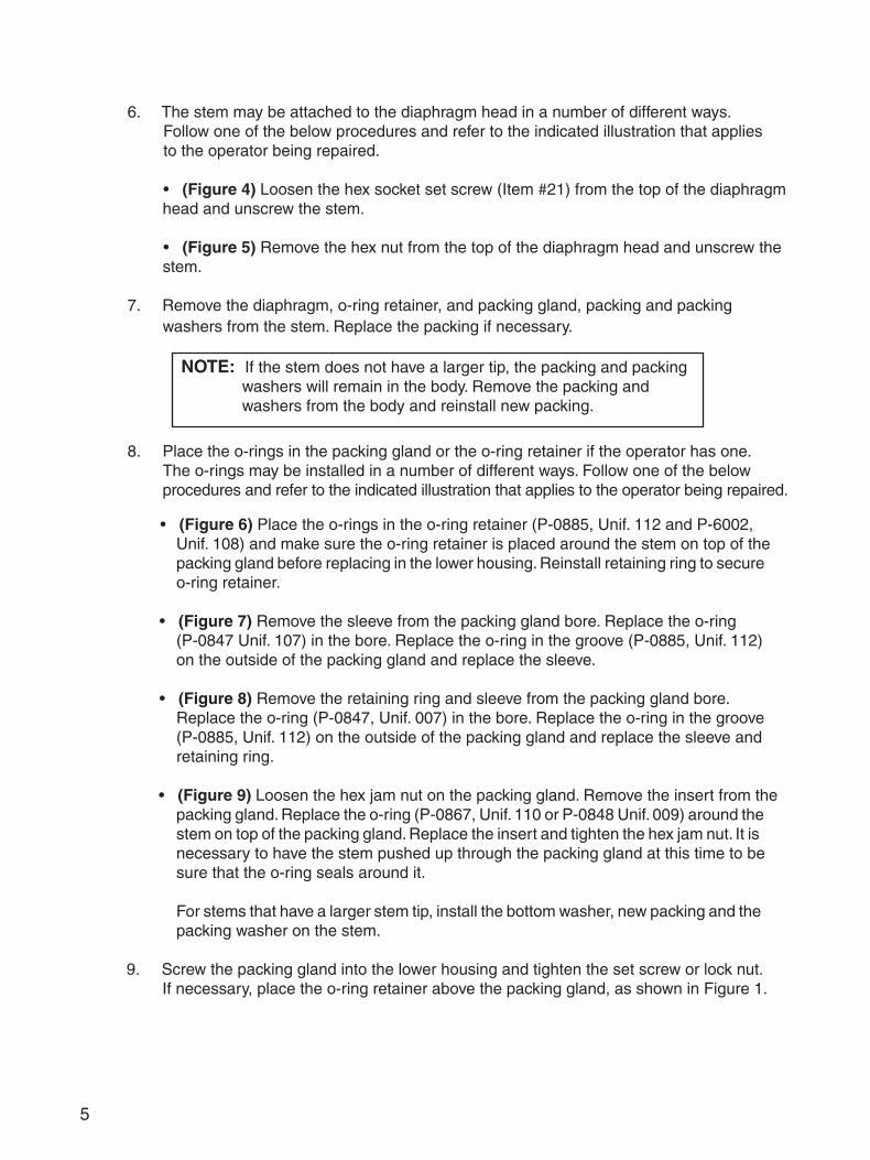
6. The stem may be attached to the diaphragm head in a number of different ways. Follow one of the below procedures and refer to the indicated illustration that applies to the operator being repaired.
• (Figure 4) Loosen the hex socket set screw (Item #21) from the top of the diaphragm head and unscrew the stem.
• (Figure 5) Remove the hex nut from the top of the diaphragm head and unscrew the stem.
7. Remove the diaphragm, o-ring retainer, and packing gland, packing and packing washers from the stem. Replace the packing if necessary.
8. Place the o-rings in the packing gland or the o-ring retainer if the operator has one. The o-rings may be installed in a number of different ways. Follow one of the below procedures and refer to the indicated illustration that applies to the operator being repaired.
5
NOTE: If the stem does not have a larger tip, the packing and packing washers will remain in the body. Remove the packing and washers from the body and reinstall new packing.
• (Figure 6) Place the o-rings in the o-ring retainer (P-0885, Unif. 112 and P-6002, Unif. 108) and make sure the o-ring retainer is placed around the stem on top of the packing gland before replacing in the lower housing. Reinstall retaining ring to secure o-ring retainer.
• (Figure 7) Remove the sleeve from the packing gland bore. Replace the o-ring (P-0847 Unif. 107) in the bore. Replace the o-ring in the groove (P-0885, Unif. 112) on the outside of the packing gland and replace the sleeve.
• (Figure 8) Remove the retaining ring and sleeve from the packing gland bore. Replace the o-ring (P-0847, Unif. 007) in the bore. Replace the o-ring in the groove (P-0885, Unif. 112) on the outside of the packing gland and replace the sleeve and retaining ring.
• (Figure 9) Loosen the hex jam nut on the packing gland. Remove the insert from the packing gland. Replace the o-ring (P-0867, Unif. 110 or P-0848 Unif. 009) around the stem on top of the packing gland. Replace the insert and tighten the hex jam nut. It is necessary to have the stem pushed up through the packing gland at this time to be sure that the o-ring seals around it.
For stems that have a larger stem tip, install the bottom washer, new packing and the packing washer on the stem.
9. Screw the packing gland into the lower housing and tighten the set screw or lock nut. If necessary, place the o-ring retainer above the packing gland, as shown in Figure 1.

6
10.Placeanewdiaphragminthelowerhousing,makingsurethatitfitsintotherecess, as shown in Figure 1. Refer to the replacement parts list for the proper diaphragm part number.
11. Place the diaphragm head over the diaphragm, place the washer onto the stem, push the stem through the packing gland, o-ring retainer and diaphragm, and attach it into the diaphragm head. If necessary, replace the tighten the set screw or hex nut depending on whichfigure(4or5)isapplicabletothestemattachment.
12. Place the spring (Item #8) over the diaphragm head and place the spring suppressor (Item #4) over the spring.
13. Place the upper housing on the lower housing, reinsert the hex head cap screws (Item #11), install the washers (Item #13) and nuts (Item #12) and gradually tighten the nuts around the perimeter of the housing.
14. Follow the instructions in Section 4.0, Steps 10-12 to install the operator to the body and adjust the spring.
6.1 CL, CM and CH Operators (refer to Figures 2 and 3 for parts diagrams).
1. Disassemble the operator from the valve body as indicated in Section 4.0, steps 1 - 5.
2. Loosen and remove the hex nuts (Item #9) around the perimeter of the housing. Re move the lock washers (Item #10) and hex head screws (Item #8) and remove the upper housing (Item #1) from the lower housing (Item #2).
CH only - remove the nut and stop from the top of the diaphragm head.
3. Remove the diaphragm (Item #4) and diaphragm head (Item #3).
4. If the stem has a larger tip below the packing and the packing or stem requires replace- ment, the stem must be removed from the diaphragm head. If not, proceed to Step 9.
5. Refer to Figure 3. Loosen the hex nut under the diaphragm head or the set screw above the diaphragm and unscrew the stem.
6. Remove the packing washer from the stem and replace the packing, if necessary.
NOTE: If the stem does not have a larger tip, the packing and packing washers will remain in the body. Remove the packing and washers from the body and replace the packing.

7
7. Slide the stem up through the packing gland and spring (Item #7).
8. Screw the stem into the diaphragm head and tighten the hex nut or hex socket set screw depending on how the stem is attached (Figure 3).
CH only - Place stop onto stem above the diaphragm head then install and tighten nut. 9. Be sure that the spring (Item #7) is sitting on top of the packing gland and the diaphragm head sits on top of the spring, as shown in Figure 2.
10.Placeanewdiaphragminthelowerhousing,makingsurethatitfitsintotherecess, as shown in Figure 2. Refer to the replacement parts list for the proper diaphragm part number.
11. Place the upper housing on the lower housing, insert the hex head cap screws (Item #8), install the washers (Item #10) and nuts (Item #9) and gradually tighten the nuts around the perimeter of the housing.
12. Follow the instructions in Section 4.0, Steps 10-12 to install the operator to the body.
7.0 SERVICE
For service, contact the Parker Autoclave Engineers Representative in your area, or FAX Parker Autoclave Engineers’ Customer Support at 1-814-860-5811.
NOTE: Make sure that the diaphragm head is free of sharp edges before installing, as it may cause damage to the diaphragm.

8
REPLACEMENT PARTS LISTS - Diaphragm Part NumberVALVE SERIES
10V2 10V4 10V6 10V8 SW4 SW6 SW8 10/20SM4 10/20SM6 10/20SM9 30VM4 30VM6 30VM9 60VM4 60VM6 60VM9
Packing Gland Hex Size in (mm)
13/16 (20.6) 13/16 (20.6) 13/16 (20.6) 15/16 (23.8) 13/16 (20.6) 15/16 (23.8) 13/16 (20.6) 13/16 (20.6) 13/16 (20.6) 13/16 (20.6) 13/16 (20.6) 13/16 (20.6) 13/16 (20.6) 13/16 (20.6) 13/16 (20.6) 13/16 (20.6) 13/16 (20.6) 13/16 (20.6) 15/16 (23.8) 15/16 (23.8) 15/16 (23.8) 1-3/8 (34.9) 13/16 (20.6) 13/16 (20.6) 13/16 (20.6)
Tube GlandHex Sizein (mm)
1/2 (12.7) 1/2 (12.7) 13/16 (20.6) 13/16 (20.6) 13/16 (20.6) 13/16 (20.6) 7/8 (22.2) 9/16 (14.3) 9/16 (14.3) 11/16 (17.5) 7/8 (22.2) 7/8 (22.2) 1/2 (12.7) 1/2 (12.7) 5/8 (15.9) 5/8 (15.9) 7/8 (22.2) 7/8 (22.2) 1-3/16 (30.2) 1-3/16 (30.2) 1-3/8 (34.9) 1-3/8 (34.9) 5/8 (15.9) 5/8 (15.9) 5/8 (15.9)
Tube GlandTorque
ft-lbs (Nm) Note 4 Note 4 Note 4 Note 4 Note 4 Note 4 Note 4 Note 4 Note 4 Note 4 Note 4 Note 4 20 (27.1) 20 (27.1) 30 (40.7) 30 (40.7) 30 (40.7) 40 (54.2) 25 (33.8) 45 (60.9) 40 (54.2) 50 (67.8) 10 (13.6) 15 (20.3) 15 (20.3)
Seat RetainerTorque
ft-lbs (Nm) 12 (16.3) 12 (16.3) 10 (13.6) 20 (27.1) 20 (27.1) 30 (40.8) 15 (20.3) 15 (20.3) 30 (40.8) 40 (54.4) 70 (95.2) 80 (108.8) 35 (47.4) 35 (47.4) 40 (54.2) 40 (54.2) 55 (74.5) 35 (47.4) 20 (27.1) 35 (47.4) 50 (67.8) 65 (81.3) 15 (20.3) 35 (47.4) 35 (47.4)
DIAPHRAGM AIR OPERATED VALVES - Installation Summary Chart - Air-to-Close
VALVE SERIES
10V2-CL 10V2-CM 10V4-CL 10V4-CM 10V6-CL 10V6-CM 10V8-CM SW4-CL SW4-CM SW6-CM SW8-CM SW8-CH 20SM4-CM 20SM4-CH 20SM6-CM 20SM6-CH 10/20SM9-CM 10/20SM9-CH 10/20SM12-CM 10/20SM12-CH 10/20SM16-CM 10/20SC16-CH 30VM4-CL 30VM4-CM 30VM4-CH
Packing Gland Torque
ft-lbs (Nm) 15 (20.4) 15 (20.4) 35 (47.4) 50 (67.8) 50 (67.8) 65 (88.4) 50 (67.8) 15 (20.3) 25 (47.3) 50 (67.8) 60 (81.6) 65 (88.4) 40 (54.2) 40 (54.2) 60 (81.3) 60 (81.3) 25 (33.9) 60 (81.3) Note 2 Note 2 Note 2 Note 2 25 (33.9) 40 (54) 40 (54)
OL
3030-1414 3030-1414 3030-1414 - - - - - - - 3030-1414 3030-1414 3030-1414 - - -
OM
105A-0226 103A-0326 103A-0326 103A-0326 105A-0326 105A-0326 105A-0326 105A-0326 105A-0326 105A-0326 103A-0326 103A-0326 103A-0326 103A-0326 103A-0326 103A-0326
OH
-------
3100-2023 3100-2023 3100-2023 3040-1897 3040-1897 3040-1897 3040-1897 3040-1897 3040-1897
CL
3030-1414 3030-1414 3030-1414 - - - - - - - 3030-1414 3030-1414 3030-1414 - - -
CM
102A-0326 102A-0326 102A-0326 102A-0326 102A-0326 102A-0326 102A-0326 102A-0326 102A-0326 102A-0326 102A-0326 102A-0326 102A-0326 102A-0326 102A-0326 102A-0326
CH
-------
3100-2023 3100-2023 3100-2023 3040-1897 3040-1897 3040-1897 3040-1897 3040-1897 3040-1897

9
Notes: 1. Torque may vary +/- 10%. Torque applies to PTFE or nylon/leather packings. Add 10% to above values for PTFE Glass and 25% to above values for graphite yarn.2. Finger tight then 3/4 turn with wrench. (PTFE only).3. Spring pre-compression required at the maximum working pressure of the valve.4. Torque wrench not required for AE SpeedBite tube connections. Tighten the gland until the sleeve begins to grip the tubing, then 1-1/4 turns.
DIAPHRAGM AIR OPERATED VALVES - Installation Summary Chart - Air-to-Close
Packing Gland Hex Size in (mm)
13/16 (20.6) 13/16 (20.6) 13/16 (20.6) 13/16 (20.6) 13/16 (20.6) 13/16 (20.6) 13/16 (20.6) 13/16 (20.6) 13/16 (20.6) 13/16 (20.6) 13/16 (20.6) 13/16 (20.6) 15/16 (23.8)
VALVE SERIES
30VM6-CL 30VM6-CM 30VM6-CH 30VM9-CL 30VM9-CM 30VM9-CH 60VM4-CM 60VM4-CH 60VM6-CM 60VM6-CH 60VM9-CM 60VM9-CH 100VM5-CH
Packing Gland Torque
ft-lbs (Nm)1
35 (47.4) 40 (54) 40 (54) 35 (47.4) 40 (54) 40 (54) 60 (81.3) 60 (81.3) 60 (81.3) 60 (81.3) 60 (81.3) 60 (81.3) 60 (81.3)
Tube GlandHex Sizein (mm)
13/16 (20.6) 13/16 (20.6) 13/16 (20.6) 1-3/16 (30.2) 1-3/16 (30.2) 1-3/16 (30.2) 5/8 (15.9) 5/8 (15.9) 13/16 (20.6) 13/16 (20.6) 1-3/16 (30.2) 1-3/16 (30.2) 11/16 (17.5)
Tube GlandTorque
ft-lbs (Nm) 10 (13.6) 25 (33.8) 25 (33.8) 10 (13.6) 55 (74.5) 55 (74.5) 25 (33.8) 25 (33.8) 50 (67.8) 50 (67.8) 110 (149.0) 110 (149.0) 110 (149.0)
Seat RetainerTorque
ft-lbs (Nm) 15 (20.3) 35 (47.4) 35 (47.4) 15 (20.3) 35 (47.4) 35 (47.4) 45 (60.9) 45 (60.9) 45 (60.9) 45 (60.9) 45 (60.9) 45 (60.9) 70 (95.2)

10
Packing Gland
Hex Size in (mm)
13/16 (20.6) 13/16 (20.6) 15/16 (23.8) 13/16 (20.6) 15/16 (23.8) 13/16 (20.6) 13/16 (20.6) 13/16 (20.6) 13/16 (20.6) 13/16 (20.6) 13/16 (20.6) 13/16 (20.6) 13/16 (20.6) 13/16 (20.6) 13/16 (20.6) 13/16 (20.6) 13/16 (20.6) 15/16 (23.8) 1-3/8 (34.9) 13/16 (20.6) 13/16 (20.6) 13/16 (20.6) 13/16 (20.6) 13/16 (20.6)
VALVE SERIES
10V2-OL 10V2-OM 10V4-OL 10V4-OM 10V6-OL 10V6-OM 10V8-OM SW4-OM SW6-OM SW8-OM SW8-OH 20SM4-OM 20SM4-OH 20SM6-OM 20SM6-OH 10/20SM9-OM 10/20SM9-OH 10/20SM12-OH 10/20SM16-OH 30VM4-OL 30VM4-OM 30VM4-OH 30VM6-OM 30VM6-OH
SpringPre-
Compressionin (mm)
0.38 (9.5) 0.25 (6.4) 0.38 (9.5) 0.38 (9.5) 0.38 (9.5) 0.22 (5.6) 0.44 (11.2) 0.46 (11.7) 0.56 (14.2) 0.56 (14.2) 0.56 (14.2) 0.56 (14.2) 0.69 (17.5) 0.56 (14.2) 0.56 (14.2) 0.44 (11.2) 0.56 (14.2) 0.38 (9.5) 0.69 (17.5) 0.69 (17.5) 0.312 (7.9) 0.44 (11.2) 0.50 (12.7) 0.38 (9.5)
Equiv-alent Turns
7.6 3.25 7.6 5 7.6 2.9 5.7 5.7 7.4 7.4 7.4 7.3 9 7.3 7.3 5.7 7.3 5 9 13.8 4 5.7 6.5 4.8
Tube Gland
Hex Sizein (mm)
1/2 (12.7) 1/2 (12.7) 13/16 (20.6) 13/16 (20.6) 13/16 (20.6) 13/16 (20.6) 7/8 (22.2) 9/16 (14.3) 11/16 (17.5) 7/8 (22.2) 7/8 (22.2) 1/2 (12.7) 1/2 (12.7) 5/8 (15.9) 5/8 (15.9) 7/8 (22.2) 7/8 (22.2) 1-3/16 (30.2) 1-3/8 (34.9) 5/8 (15.9) 5/8 (15.9) 5/8 (15.9) 13/16 (20.6) 13/16 (20.6)
Tube GlandTorqueft-lbs (Nm)
Note 4 Note 4 Note 4 Note 4 Note 4 Note 4 Note 4 Note 4 Note 4 Note 4 Note 4 20 (27.1) 20 (27.1) 30 (40.7) 30 (40.7) 30 (40.7) 40 (54.2) 45 (60.9) 50 (67.8) 10 (13.6) 15 (20.3) 15 (20.3) 25 (33.9) 25 (33.9)
DIAPHRAGM AIR OPERATED VALVES - Installation Summary Chart - Air-to-Open
VALVE SERIES
30VM9-OM 30VM9-OH 60VM4-OM 60VM4-OH 60VM6-OM 60VM6-OH 60VM9-OM 60VM9-OH 100VM5-OH
Packing Gland
Hex Size in (mm)
13/16 (20.6) 13/16 (20.6) 13/16 (20.6) 13/16 (20.6) 13/16 (20.6) 13/16 (20.6) 13/16 (20.6) 13/16 (20.6) 15/16 (23.8)
Seat RetainerTorqueft-lbs (Nm)
35 (47.4) 35 (47.4) 45 (60.9) 45 (60.9) 45 (60.9) 45 (60.9) 45 (60.9) 45 (60.9)
70 (95.2)
Equivalent Turns
6.5 4.8 4.8 6.5 4.8 6.5 7.3 13.8 7.3
SpringPre-
Compressionin (mm)
0.5 (12.7) 0.38 (9.5) 0.38 (9.5) 0.5 (12.7) 0.38 (9.5) 0.5 (12.7) 0.56 (14.2) 0.69 (17.5) 0.56 (14.2)
Tube Gland
Hex Sizein (mm)
1-3/16 (30.2) 1-3/16 (30.2) 5/8 (15.9) 5/8 (15.9) 13/16 (20.6) 13/16 (20.6) 1-3/16 (30.2) 1-3/16 (30.2) 11/16 (17.5)
Tube GlandTorqueft-lbs (Nm)
55 (74.5) 55 (74.5) 25 (33.8) 25 (33.8) 50 (67.8) 50 (67.8) 110 (149.0) 110 (149.0) 110 (149.0)
DIAPHRAGM AIR OPERATED VALVES - Installation Summary Chart - Air-to-Open
Notes: 1. Torque may vary +/- 10%. Torque applies to PTFE or nylon/leather packings. Add 10% to above values for PTFE Glass and 25% to above values for graphite yarn.2. Finger tight then 3/4 turn with wrench. (PTFE only).3. Spring pre-compression required at the maximum working pressure of the valve.4. Torque wrench not required for AE SpeedBite tube connections. Tighten the gland until the sleeve begins to grip the tubing, then 1-1/4 turns.
Packing Gland Torque ft-lbs (Nm)
40 (54) 40 (54) 60 (81.3) 60 (81.3) 60 (81.3) 60 (81.3) 60 (81.3) 60 (81.3) 45 (61.4)
Packing Gland Torque ft-lbs (Nm)
10 (13.6) 15 (20.4) 35 (47.4) 50 (68.0) 35 (47.4) 50 (68.0) 50 (67.8) 35 (47.6) 40 (54.4) 50 (67.8) 65 (88.4) 60 (81.3) 60 (81.3) 40 (54.2) 60 (81.3) 25 (33.9) 65 (88.0) Note 2 Note 2 25 (33.9) 40 (54) 40 (54) 40 (54) 40 (54)
Seat RetainerTorqueft-lbs (Nm)
10 (13.6) 12 (16.3) 10 (13.6) 20 (27.2) 10 (13.6) 20 (27.2) 15 (20.3) 30 (40.8) 50 (68.0) 50 (67.8) 80(108.8) 35 (47.4) 40 (54.2) 35 (47.4) 40 (54.2) 55 (74.6) 55 (74.6) 80 (108) 65 (81.3) 15 (20.3) 35 (47.4) 35 (47.4) 35 (47.4) 35 (47.4)

11
-OMfigure#1
14
22 5
2
61
8
4
3
10
9
29
11
13
12
23
15
21
16
17
18
20
7
19
24

12
-CMfigure#2
5
7
6
17
18
13
15
14
16
12
11
2
23 341

13
-CH ONLYfigure#3
figure#4
HEX NUT
SET SCREW
HEX NUT
WASHER
HEX NUT (-OH ONLY)
figure#5
WASHER

14
figure#6OM OPERATOR 1/8” 1OV, ALL SW 8 20SM VALVES
figure#7OL OPERATORS
RETAINING RING
O-RING RETAINER
O-RING P-6002 (UNIF #108)O-RING P-0885 (UNIF #112)
O-RING P-0885 (UNIF #112)
O-RING P-0847 (UNIF #007)
SLEEVE
CAUTION: While testing has shown O-rings to provide satisfactory service life, both cyclic and shelf life may vary widely with differing service conditions, properties of reactants, pressure and temperature cycling and age of the O-ring, FREQUENT INSPECTIONS SHOULD BE MADE to detect any deterioration, and O-rings replaced as required.

15
figure#8OM OPERATOR 1/4, 3/8, 1/2 1OV & ALL 30VM & 60VM VALVES
figure#9OH OPERATORS
RETAINING RING
O-RING P-0885 (UNIF #112)
O-RING P-0847 (UNIF #007)
SLEEVE
O-RING P-0867 (UNIF #110) OR P-0848 (UNIF #009)
PACKING GLAND
HEX NUT
CAUTION: While testing has shown O-rings to provide satisfactory service life, both cyclic and shelf life may vary widely with differing service conditions, properties of reactants, pressure and temperature cycling and age of the O-ring, FREQUENT INSPECTIONS SHOULD BE MADE to detect any deterioration, and O-rings replaced as required.

ValveSeries Operator Duty
Medium Duty
AirPressurepsi (bar)
System Pressure KSI (Mpa)Maximum Pressure psi (bar)*
Stem Travel in (mm)
FlowCoefficient**
10V2
1-4 6 8 10 12 14 15 (6.89-27.57) (41.37) (55.16) (68.95) (82.74) (96.53) (103.42)
30 40 55 65 85 95 100 15,000 0.16 0.12 (2.07) (2.76) (3.79) (4.48) (5.86) (6.55) (6.89) (1034.20) (4.06)
25 25 25 25 25 25 30 (1.72) (1.72) (1.72) (1.72) (1.72) (1.72) (2.07)
Light Duty
Medium Duty10V4
Light Duty 40 60 75 95 10,000 0.19 0.20 (2.76) (4.13) (5.17) (6.55) (689.46) (4.83)
30 30 30 30 35 35 40 15,000 (2.07) (2.07) (2.07) (2.07) (2.41) (2.41) (2.76) (1034.20)
Medium Duty10V6
Light Duty 40 60 75 100 10,000 0.19 0.20 (2.76) (4.13) (5.17) (6.89) (689.46) (4.83)
30 30 30 35 35 35 40 15,000 (2.07) (2.07) (2.07) (2.41) (2.41) (2.41) (2.76) (1034.20)
Medium Duty
10V8 Medium Duty 50 50 55 65 75 85 90 10,000 0.31 0.086 (3.45) (3.45) (3.79) (4.48) (5.10) (5.86) (6.21) (689.46) (7.90)
40 40 40 50 55 60 65 15,000 0.25 0.065 (2.76) (2.76) (2.76) (3.45) (3.79) (4.13) (4.48) (1034.20) (6.40)
Medium Duty
SW6Medium Duty
50 50 55 70 75 85 90 15,000 0.25 0.095 (3.45) (3.45) (3.79) (4.83) (5.17) (5.86) (6.21) (1034.20) (6.40)
65 70 100 8,500 0.38 1.90 (4.48) (4.83) (6.89) (586.46) (9.70)
Heavy DutySW8
35 35 50 60 10,000 (2.41) (2.41) (3.45) (4.13) (698.46)
SW4
Heavy Duty 20 25 30 35 40 45 50 15,000 (1.38) (1.72) (2.07) (2.41) (2.76) (3.10) (3.45) (1034.20)
AirPressurepsi (bar)
Heavy Duty10SM12
Medium Duty 90 100 4,800 0.44 2.80 (6.21) (6.89) (330.94) (11.18)
45 45 60 80 100 10,000 (3.10) (3.10) (4.13) (5.52) (6.89) (689.46)
Heavy Duty10SM16
Medium Duty 100 2,800 0.56 5.20 (6.89) (193.05) (14.22)
60 70 100 6,300 (4.13) (4.83) (6.89) (434.36)
ValveSeries Operator Duty System Pressure KSI (Mpa)
Maximum Pressure psi (bar)*
Stem Travel in (mm)
FlowCoefficient**
1-3 4 6 8 10 12 14 16 18 20 (6.89-20.68) (27.58) (41.37) (55.16) (68.95) (82.74) (96.53) (110.31) (124.10) (137.89)
Heavy Duty10SM9
Medium Duty 65 65 75 100 8,600 0.38 1.75 (4.48) (4.48) (5.17) (6.89) (592.94) (9.65)
35 35 40 50 55 10,000 (2.41) (2.41) (2.76) (3.45) (3.79) (689.46)
Series 10SM
Series 10V and SW ValvesAir-to-Close -
** Cv data is for 2-way straight valves.For angle pattern, add approximately 50% to the CV valve.
*Maximum pressure rating is based on the lowest rating of any component. Actual working pressure may be determined by tubing pressure rating, if lower.
All dimensions for reference only and subject to change.For prompt service, Parker Autoclave stocks select products. Consult your local representative.
NOTE: OperatorSuffix:CL - Light Duty CM - Medium Duty CH - Heavy Duty
16

17
ValveSeries Operator Duty
Heavy Duty
AirPressurepsi (bar)
System Pressure KSI (Mpa)Maximum Pressure psi (bar)*
Stem Travel in (mm)
FlowCoefficient**
20SM4
1-3 4 6 8 10 12 14 16 18 20 (6.89-20.68) (27.58) (41.37) (55.16) (68.95) (82.74) (96.53) (110.31) (124.10) (137.89)
40 40 40 40 50 60 70 80 85 95 20,000 0.25 0.31 (2.76) (2.76) (2.76) (2.76) (3.45) (4.13) (4.83) (5.52) (5.86) (6.55) (1378.93) (6.35) Medium Duty
Heavy Duty20SM6
Medium Duty
Heavy Duty20SM9
Medium Duty 60 60 65 80 100 10,700 0.38 1.30 (4.13) (4.13) (4.48) (5.52) (6.89) (737.73) (9.65)
30 30 30 40 50 55 60 70 80 85 20,000 (2.07) (2.07) (2.07) (2.76) (3.45) (3.79) (4.13) (4.83) (5.52) (5.86) (1378.93)
Series 20SM Valves
45 45 45 45 55 65 75 85 95 100 19,000 0.25 0.75 (3.10) (3.10) (3.10) (3.10) (3.79) (4.48) (5.17) (5.86) (6.55) (6.89) (1309.98) (6.35)
25 25 25 25 30 35 40 45 50 55 20,000 (1.72) (1.72) (1.72) (1.72) (2.07) (2.41) (2.76) (3.10) (3.45) (3.79) (1378.93)
20SM16
Heavy Duty20SM12
Medium Duty 80 80 100 6,100 0.44 2.50 (5.44) (5.44) (6.80) (420.57) (11.18)
40 40 50 60 75 90 100 13,600 (2.72) (2.72) (3.40) (4.08) (5.10) (6.12) (6.80) (937.67)
Heavy Duty
Medium Duty 100 100 3,900 0.56 3.40 (6.89) (6.89) (268.89) (14.22)
50 50 70 100 8,800 (3.45) (3.45) (4.83) (6.89) (606.73)
Air-to-Close -
20 20 20 20 25 30 35 40 45 50 (1.38) (1.38) (1.38) (1.38) (1.72) (2.07) (2.41) (2.76) (3.10) (3.45)
** Cv data is for 2-way straight valves.For angle pattern, add approximately 50% to the CV valve.
*Maximum pressure rating is based on the lowest rating of any component. Actual working pressure may be determined by tubing pressure rating, if lower.
All dimensions for reference only and subject to change.For prompt service, Parker Autoclave stocks select products. Consult your local representative.
NOTE: OperatorSuffix:CL - Light Duty CM - Medium Duty CH - Heavy Duty
ValveSeries Operator Duty
Heavy Duty
System Pressure KSI (Mpa)Maximum Pressure psi (bar)*
Stem Travel in (mm)
FlowCoefficient**
30VM4
1-10 12 14 16 18 20 22 24 26 28 30 (6.89-68.94) (82.74) (96.53) (110.31) (124.10) (137.89) (151.68) (165.47) (179.26) (193.05) (206.84)
25 25 25 30 35 35 40 45 50 50 55 30,000 0.19 0.12 (1.72) (1.72) (1.72) (2.07) (2.41) (2.41) (2.76) (3.10) (3.45) (3.45) (3.79) (2068.39) (4.83)
15 15 15 15 20 20 20 25 25 25 30 (1.03) (1.03) (1.03) (1.03) (1.38) (1.38) (1.38) (1.72) (1.72) (1.72) (2.07)
Medium Duty
Heavy Duty
30VM6 &
30VM9
Medium Duty
Series 30VM Valves
30 30 35 40 45 50 55 60 65 70 75 30,000 0.19 0.23 (2.07) (2.07) (2.41) (2.76) (3.10) (3.45) (3.79) (4.13) (4.48) (4.83) (5.17) (2068.39) (4.83) (30VM6)
15 15 20 20 25 25 30 30 35 35 40 0.33 (1.03) (1.03) (1.38) (1.38) (1.72) (1.72) (2.07) (2.07) (2.41) (2.41) (2.76) (30VM9)
AirPressurepsi (bar)
ValveSeries Operator Duty
Heavy Duty
System Pressure KSI (Mpa)Maximum Pressure psi (bar)*
Stem Travel in (mm)
FlowCoefficient**
40VM9
1-10 15 20 25 30 35 40 ( 6.89-68.94) (103.42) (137.89) (172.37) (206.84) (241.31) (275.79)
40 50 60 70 80 90 90 40,000 0.25 0.28 (2.76) (3.45) (4.13) (4.83) (5.52) (6.21) (6.21) (2757.86) (6.35)
20 25 30 35 40 45 45 (1.38) (1.70) (2.07) (2.41) (2.76) (3.10) (3.10)
Medium Duty AirPressurepsi (bar)
Series 40VM Valves

18
Air-to-Close - Series 60VM ValvesValveSeries Operator Duty
Heavy Duty
System Pressure KSI (Mpa)Maximum Pressure psi (bar)*
Stem Travel in (mm)
FlowCoefficient**
60VM4&
60VM6
1-20 25 30 35 40 45 50 55 60 (6.89-137.89) (172.37) (206.84) (241.31) (275.79) (310.26) (344.73) (379.21) (413.68)
30 30 35 45 50 55 60 70 75 60,000 0.25 0.08 (2.07) (2.07) (2.41) (3.10) (3.45) (3.79) (4.13) (4.83) (5.17) (4136.79) (6.35) (60VM4)
15 15 20 25 25 30 30 35 40 0.09 (1.03) (1.03) (1.38) (1.72) (1.72) (2.07) (2.07) (2.41) (2.76) (60VM6)
Medium Duty
Heavy Duty60VM9
Medium Duty 35 40 50 55 65 70 75 85 90 60,000 0.25 0.14 (2.41) (2.76) (3.45) (3.79) (4.48) (4.83) (5.17) (5.86) (6.21) (4136.79) (6.35)
20 20 25 30 35 35 40 45 45 (1.38) (1.38) (1.72) (2.07) (2.41) (2.41) (2.76) (3.10) (3.10)
AirPressurepsi (bar)
ValveSeries Operator Duty
Heavy Duty
System Pressure KSI (Mpa)Maximum Pressure psi (bar)*
Stem Travel in (mm)
FlowCoefficient**
100VM4100VM5100VM6
1-40 50 60 70 80 90 100 150 (6.89-275.79) (344.73) (413.68) (482.63) (551.57) (620.52) (689.46) (1034.20)
50 55 65 75 85 95 100 100,000 0.12 0.09 (3.45) (3.79) (4.48) (5.17) (5.86) (6.55) (6.89) (6894.65) (3.05)
30 30 35 40 40 45 50 (2.07) (2.07) (2.41) (2.76) (2.76) (3.10) (3.45)
Medium Duty
Series 100VM & 150V Valves
AirPressurepsi (bar)
NOTE: OperatorSuffix:CL - Light Duty CM - Medium Duty CH - Heavy Duty** Cv data is for 2-way straight valves.For angle pattern, add approximately 50% to the CV valve.
*Maximum pressure rating is based on the lowest rating of any component. Actual working pressure may be determined by tubing pressure rating, if lower.
All dimensions for reference only and subject to change.For prompt service, Autoclave stocks select products. Consult your local representative.

ValveSeries Operator Duty System Pressure KSI (Mpa)
10V2
1-6 8 10 12 14 15 (6.89-41.37) (110.31) (124.10) (82.74) (96.53) (103.42)
60 60 (4.13) (4.13)
Light Duty
0.12 0.06 (3.05) (1.52)
Air Pressure: psi (bar)
Spring Pre-Compression:in. (mm)
Stem Travel in (mm)
Maximum Pressure psi (bar)*
Flow Coefficient Cv**
40 40 40 40 40 45 15,000 0.12 (2.76) (2.76) (2.76) (2.76) (2.76) (3.10) (1034.20)
Medium Duty 0.12 0.12 0.12 0.12 0.12 0.16 (3.05) (3.05) (3.05) (3.05) (3.05) (4.06)
0.12 0.12 0.12 0.12 0.12 0.12 (3.05) (3.05) (3.05) (3.05) (3.05) (3.05)
Air Pressure: psi (bar)
Spring Pre-Compression:in. (mm)
Stem Travel in (mm)
10V4 10V6
60 (4.13)
Light Duty
0.06 (1.52)
Air Pressure: psi (bar)
Stem Travel in (mm)
10V4
45 45 50 55 60 65 (3.10) (3.10) (3.45) (3.79) (4.14) (4.48)
Medium Duty
0.19 0.19 0.19 0.19 0.19 0.19 (4.83) (4.83) (4.83) (4.83) (4.83) (4.83)
Air Pressure: psi (bar)
Spring Pre-Compression:in. (mm)
Stem Travel in (mm)
10V6
45 45 50 55 60 65 (3.10) (3.10) (3.45) (3.79) (4.13) (4.48)
Medium Duty 0.12 0.12 0.14 0.18 0.20 0.22 15,000 0.20 (3.05) (3.05) (3.56) (4.57) (5.08) (5.57) (1034.20)
0.19 0.19 0.19 0.19 0.19 0.19 (4.83) (4.83) (4.83) (4.83) (4.83) (4.83)
Air Pressure: psi (bar)
Stem Travel in (mm)
10V8
75 85 95 (5.17) (5.86) (6.55)
Medium Duty 0.25 0.30 0.38 10,000 0.86 (6.35) (7.62) (9.65) (689.46) 0.25 0.25 0.25 (6.35) (6.35) (6.35)
Air Pressure: psi (bar)
Spring Pre-Compression:in. (mm)
Stem Travel in (mm)
Spring Pre-Compression:in. (mm)
Spring Pre-Compression:in. (mm)
0.38 5,600 0.02 (9.65) (386.46) to 0.17***
0.31 0.38 8,200 0.12 (7.87) (9.65) (565.36) to 0.09***
50 55 60 (3.45) (3.79) (4.13)
Heavy Duty 0.14 0.20 0.24 10,000 0.86 (3.56) (5.08) (6.10) (689.46) 0.25 0.25 0.25 (6.35) (6.35) (6.35)
Air Pressure: psi (bar)
Spring Pre-Compression:in. (mm)
Stem Travel in (mm)
0.12 0.12 0.14 0.18 0.20 0.22 15,000 0.20 (3.05) (3.05) (3.65) (4.75) (5.08) (5.59) (1034.20)
Air-to-Open - Series 10V Valves
NOTE: OperatorSuffix:OL - Light Duty OM - Medium Duty OH - Heavy Duty** Cv data is for 2-way straight valves.For angle pattern, add approximately 50% to the CV valve.
*** Cvvariesbecauseofspringcompressionlimitations.Theflowcoefficientrangeisgivenforthemaximumstemtravel(lowestsystempressure) to minimum travel (highest system pressure).
*Maximum pressure rating is based on the lowest rating of any component. Actual working pressure may be determined by tubing pressure rating, if lower.
All dimensions for reference only and subject to change.For prompt service, Parker Autoclave stocks select products. Consult your local representative.
19

Spring Pre-Compression:in. (mm)
ValveSeries Operator Duty System Pressure KSI (Mpa)
SW4
1-6 8 10 12 14 15 (6.89-41.37) (55.16) (68.95) (82.74) (96.53) (103.41)
65 65 75 85 95 95 (4.48) (4.48) (5.17) (5.52) (6.55) (6.55)
Medium Duty 0.19 0.19 0.25 0.31 0.36 0.38 15,000 0.065 (4.83) (4.83) (6.35) (7.87) (9.14) (9.14) (1034.20)
0.25 0.25 0.25 025 025 025 (6.35) (6.35) (6.35) (6.35) (6.35) (6.35)
Air Pressure: psi (bar)
Spring Pre-Compression:in. (mm)
Stem Travel in (mm)
75 75 95 95 95 100 (5.17) (5.17) (6.55) (6.55) (6.55) (6.89)
Medium Duty 0.25 0.25 0.28 0.44 0.52 0.56 13,500 0.62 (6.35) (6.35) (7.11) (11.17) (13.21) (14.22) (930.77) to 0.95 0.25 0.25 0.25 0.19 0.10 0.06 (6.35) (6.35) (6.35) (4.83) (2.54) (1.53)
Air Pressure: psi (bar)
Spring Pre-Compression:in. (mm)
Stem Travel in (mm)
50 55 60 65 70 75 (3.45) (3.79) (4.13) (4.48) (4.83) (5.17)
Heavy Duty 0.14 0.19 0.24 0.28 0.34 0.36 15,000 0.95 (3.56) (4.83) (6.10) (7.11) (8.64) (9.14) (1034.20)
0.25 0.25 0.25 0.25 0.25 0.25 (6.35) (6.35) (6.35) (6.35) (6.35) (6.35)
Air Pressure: psi (bar)
Spring Pre-Compression:in. (mm)
Stem Travel in (mm)
SW6
95 95 (6.55) (6.55)
Medium Duty 0.38 0.56 7,200 1.75 (9.65) (14.22) (469.41) 0.25 0.05 (6.35) (1.53)
Air Pressure: psi (bar)
Stem Travel in (mm)
SW8
65 75 75 (4.48) (5.17) (5.17)
Heavy Duty 0.28 0.38 0.44 10,000 1.14 (7.11) (9.65) (11.18) (689.46)
0.25 0.25 0.19 (6.35) (6.35) (4.83)
Air Pressure: psi (bar)
Spring Pre-Compression:in. (mm)
Stem Travel in (mm)
SW8
Maximum Pressure psi (bar)*
Flow Coefficient Cv**
Air-to-Open - Series SW Valves
SW6
** Cv data is for 2-way straight valves.For angle pattern, add approximately 50% to the CV valve.
*Maximum pressure rating is based on the lowest rating of any component. Actual working pressure may be determined by tubing pressure rating, if lower.
All dimensions for reference only and subject to change.For prompt service, Parker Autoclave stocks select products. Consult your local representative.
NOTE: OperatorSuffix:OL - Light Duty OM - Medium Duty OH - Heavy Duty
20

ValveSeries Operator Duty System Pressure KSI (Mpa)
10SM9
1-4 6 8 10 12 14 16 18 20 (6.89-27.58) (41.37) (55.15) (68.95) (82.74) (96.53) (110.31) (124.10) (137.89)
95 95 95 (6.55) (6.55) (6.55)
0.38 0.44 0.56 7,900 1.74 to 0.72*** (9.65) (11.18) (14.22) (544.68)
0.25 0.19 0.06 (6.35) (4.83) (1.52)
55 65 70 75 (3.79) (4.48) (4.83) (5.17)
0.22 0.28 0.34 0.44 10,000 1.74 to 0.72*** (5.59) (7.11) (8.64) (11.18) (689.46)
0.25 0.25 0.25 0.19 (6.35) (6.35) (6.35) (4.83)
70 75 (4.83) (5.17)
0.24 0.56 7,000 2.23 to 0.78*** (6.10) (14.22) (482.63)
0.25 0.06 (6.35) (1.52)
Series 10SM Valves
10SM12
Air-to-Open -
Medium Duty
Air Pressure: psi (bar)
Spring Pre-Compression:in. (mm)
Stem Travel in (mm)
Heavy Duty
Air Pressure: psi (bar)
Spring Pre-Compression:in. (mm)
Stem Travel in (mm)
Air Pressure: psi (bar)
Spring Pre-Compression:in. (mm)
Stem Travel in (mm)
Heavy Duty
Heavy Duty
Air Pressure: psi (bar)
Spring Pre-Compression:in. (mm)
Stem Travel in (mm)
75 (5.17)
0.56 4,300 0.79 (14.22) (296.47)
0.06 (1.52)
10SM16
Maximum Pressure psi (bar)*
Flow Coefficient Cv**
** Cv data is for 2-way straight valves. For angle pattern, add approximately 50% to the Cv valve.*** Cvvariesbecauseofspringcompressionlimitations.Theflowcoefficientrangeisgivenforthemaximumstem travel (lowest system pressure) to minimum travel (highest system pressure).
NOTE: OperatorSuffix:OL - Light Duty OM - Medium Duty OH - Heavy Duty
Air Pressure: psi (bar)
Spring Pre-Compression:in. (mm)
Stem Travel in (mm)
Medium Duty
Heavy Duty
20SM9Air Pressure: psi
(bar)
Spring Pre-Compression:in. (mm)
Stem Travel in (mm)
65 65 65 75 85 95 95 95 95 (4.48) (4.48) (4.48) (5.17) (5.86) (6.55) (6.55) (6.55) (6.55)
0.19 0.19 0.19 0.25 0.31 0.38 0.44 0.50 0.56 (4.83) (4.83) (4.83) (6.35) (7.87) (9.65) (11.18) (12.70) (14.22)
0.25 0.25 0.25 0.25 0.25 0.25 0.19 0.12 0.06 20,000 0.31 to 0.22*** (6.35) (6.35) (6.35) (6.35) (6.35) (6.35) (4.83) (3.05) (1.52) (1378.93)
35 35 35 40 45 50 50 50 50 (2.41) (2.41) (2.41) (2.76) (3.10) (3.45) (3.45) (3.45) (3.45)
Air Pressure: psi (bar)Medium Duty
Spring Pre-Compression:in. (mm)
Stem Travel in (mm)
Air Pressure: psi (bar)Heavy Duty
20SM4
ValveSeries Operator Duty System Pressure KSI (Mpa)
1-4 6 8 10 12 14 16 18 20 (6.89-27.58) (41.37) (55.15) (68.95) (82.74) (96.53) (110.31) (124.10) (137.89)
65 65 75 85 95 95 95 95 (4.48) (4.48) (5.17) (5.86) (6.55) (6.55) (6.55) (6.55)
0.19 0.19 0.25 0.31 0.38 0.44 0.50 0.56 (4.83) (4.83) (6.35) (7.87) (9.65) (11.18) (12.70) (14.22)
0.25 0.25 0.25 0.25 0.25 0.19 0.12 0.06 18,250 0.75 to 0.57*** (6.35) (6.35) (6.35) (6.35) (6.35) (4.83) (3.05) (1.52) (1258.27)
35 35 40 45 50 50 50 50 (2.41) (2.41) (2.76) (3.10) (3.45) (3.45) (3.45) (3.45)
Air Pressure: psi (bar)Medium Duty
Spring Pre-Compression:in. (mm)
Stem Travel in (mm)
Air Pressure: psi (bar)Heavy Duty
20SM6
85 90 95 95 (5.86) (6.21) (6.55) (6.55)
0.31 0.34 0.47 0.56 9,800 1.29 to 0.53*** (7.87) (8.64) (11.94) (14.22) (675.68)
0.25 0.25 0.15 0.06 (6.35) (6.35) (3.81) (1.52)
50 55 65 70 75 75 75 (3.45) (3.79) (4.48) (4.83) (5.17) (5.17) (5.17)
0.19 0.22 0.28 0.34 0.44 0.50 0.56 15,700 1.29 to 0.53*** (4.83) (5.59) (7.11) (8.64) (11.18) (12.70) (14.22) (1082.46)
0.25 0.25 0.25 0.25 0.19 0.12 0.06 (6.35) (6.35) (6.35) (6.35) (4.83) (3.05) (1.52)
Maximum Pressure psi (bar)*
Flow Coefficient Cv**
Series 20SM Valves
All dimensions for reference only and subject to change.For prompt service, Parker Autoclave stocks select products. Consult your local representative.
21 *Maximum pressure rating is based on the lowest rating of any component. Actual working pressure may be determined by tubing pressure rating, if lower.

ValveSeries Operator Duty System Pressure KSI (Mpa) Maximum Pressure
psi (bar)*
40VM9
1-10 15 20 25 30 35 40 (6.89-68.95) (103.42) (137.89) (172.37) (206.84) (241.31) (275.79)
60 70 75 85 95 100 100 (4.13) (4.83) (5.17) (5.86) (6.55) (6.89) (6.89) Medium Duty
Series 40VM Valves
0.12 0.18 0.25 0.31 0.38 0.43 0.5 40,000 0.28 (3.05) (4.57) (6.35) (7.87) (9.65) (10.92) (12.70) (2757.86)
0.25 0.25 0.25 0.25 0.25 0.25 0.25 (6.35) (6.35) (6.35) (6.35) (6.35) (6.35) (6.35)
Air Pressure: psi (bar)
Stem Travel in (mm)
Flow Coefficient Cv**
Air Pressure: psi (bar)Heavy Duty 30 35 40 45 50 50 55
(2.07) (2.41) (2.76) (3.10) (3.45) (3.45) (3.79)
Spring Pre-Compression: in (mm)
ValveSeries Operator Duty System Pressure KSI (Mpa) Maximum Pressure
psi (bar)*
30VM4
1-10 12 14 16 18 20 22 24 26 28 30 (6.89-68.95) (82.74) (96.53) (110.31) (124.10) (137.89) (151.68) (165.47) (179.26) (193.05) (206.84)
45 45 55 55 55 55 65 65 65 65 75 (3.10) (3.10) (3.79) (3.79) (3.79) (3.79) (4.48) (4.48) (4.48) (4.48) (5.17) Medium Duty
Series 30VM Valves
0.12 0.12 0.19 0.19 0.19 0.19 0.25 0.25 0.25 0.25 0.31 30,000 0.12 (3.15) (3.05) (4.83) (4.83) (4.83) (4.83) (6.35) (6.35) (6.35) (6.35) (7.87) (2068.39)
0.19 0.19 0.19 0.19 0.19 0.19 0.19 0.19 0.19 0.19 0.19 (4.83) (4.83) (4.83) (4.83) (4.83) (4.83) (4.83) (4.83) (4.83) (4.83) (4.83)
Air Pressure: psi (bar)
Spring Pre-Compression:in. (mm)
Stem Travel in (mm)
Flow Coefficient Cv**
Air Pressure: psi (bar)Heavy Duty 25 25 30 30 30 30 35 35 35 35 40
(1.72) (1.72) (2.07) (2.07) (2.07) (2.07) (2.41) (2.41) (2.41) (2.41) (2.76) 45 55 55 65 65 75 75 75 85 85 95 (3.10) (3.79) (3.79) (4.48) (4.48) (5.17) (5.17) (5.17) (5.86) (5.86) (6.55) Medium Duty
0.12 0.19 0.19 0.25 0.25 0.31 0.31 0.31 0.38 0.38 0.44 30,000 0.33 (3.05) (4.83) (4.83) (6.35) (6.35) (7.87) (7.87) (7.87) (9.65) (9.65) (11.18) (2068.39) (30VM6)
0.19 0.19 0.19 0.19 0.19 0.19 0.19 0.19 0.19 0.19 0.19 0.33 (4.13) (4.83) (4.83) (4.83) (4.83) (4.83) (4.83) (4.83) (4.83) (4.83) (4.83) (30VM9)
Air Pressure: psi (bar)
Spring Pre-Compression:in. (mm)
Stem Travel in (mm)
Air Pressure: psi
(bar)Heavy Duty 25 30 30 35 35 40 40 40 45 45 50 (1.72) (2.07) (2.07) (2.41) (2.41) (2.76) (2.76) (2.76) (3.10) (3.10) (3.45)
30VM6&
30VM9
** Cv data is for 2-way straight valves.For angle pattern, add approximately 50% to the CV valve.
*** Cvvariesbecauseofspringcompressionlimitations.Theflowcoefficientrangeisgivenforthemaximumstemtravel(lowestsystempressure) to minimum travel (highest system pressure).
*Maximum pressure rating is based on the lowest rating of any component. Actual working pressure may be determined by tubing pressure rating, if lower.
All dimensions for reference only and subject to change.For prompt service, Parker Autoclave stocks select products. Consult your local representative.
NOTE: OperatorSuffix:OL - Light Duty OM - Medium Duty OH - Heavy Duty
ValveSeries Operator Duty System Pressure KSI (Mpa)
1-4 6 8 10 12 14 16 18 20 (6.89-27.58) (41.37) (55.15) (68.95) (82.74) (96.53) (110.31) (124.10) (137.89)
65 75 75 (4.48) (5.17) (5.17)
0.28 0.38 0.56 (7.11) (9.65) (14.22)
0.25 0.25 0.06 (6.35) (6.35) (1.52)
Air Pressure: psi (bar)
Spring Pre-Compression:in. (mm)
Stem Travel in (mm)
Heavy Duty20SM12
Series 20SM ValvesAir-to-Open -
9,200 0.80 to 0.78*** (634.313)
20SM16
75 75 (5.17) (5.17)
0.38 0.56 6,100 2.73 to .15*** (9.65) (14.22) (420.57)
0.25 0.06 (6.35) (1.52)
Maximum Pressure psi (bar)*
Flow Coefficient Cv**
Air Pressure: psi (bar)
Spring Pre-Compression:in. (mm)
Stem Travel in (mm)
Heavy Duty
22

ValveSeries Operator Duty System Pressure KSI (Mpa) Maximum Pressure
psi (bar)*
1-20 40 60 80 90 100 125 150 (6.89-137.89) (275.79) (13.68) (551.57) (620.52) (689.46) (861.83) (1034.20)
35 40 50 60 70 70 (2.41) (2.76) (3.45) (4.14) (4.83) (4.83)
Heavy Duty
Series 100VM and 150V Valves
Air Pressure: psi (bar)
Spring Pre-Compression:in. (mm)
Stem Travel in (mm)
Flow Coefficient Cv**
ValveSeries Operator Duty System Pressure KSI (Mpa)
60VM9
1-15 20 25 30 35 40 45 50 55 60 (6.89-103.42) (137.89) (172.37) (206.84) (241.31) (275.79) (310.26) (344.73) (379.21) (413.68)
55 65 65 65 75 75 85 85 85 95 (3.79) (4.48) (4.48) (4.48) (5.17) (5.17) (5.86) (5.86) (5.86) (6.55) Medium Duty
Series 60VM Valves
0.12 0.19 0.19 0.19 0.25 0.25 0.31 0.31 0.31 0.38 60,000 0.08 (3.05) (4.83) (4.83) (4.83) (6.35) (6.35) (7.87) (7.87) (7.87) (9.65) (4136.79) (60VM4)
0.25 0.25 0.25 0.25 0.25 0.25 0.25 0.25 0.25 0.25 (6.35) (6.35) (6.35) (6.35) (6.35) (6.35) (6.35) (6.35) (6.35) (6.35)
Air Pressure: psi (bar)
Spring Pre-Compression:in. (mm)
Stem Travel in (mm)
Air Pressure: psi (bar)Heavy Duty 30 35 35 35 40 40 45 45 45 50 0.09
(2.07) (2.41) (2.41) (2.41) (2.76) (2.76) (3.10) (3.10) (3.10) (3.45) (60VM6) 55 65 65 75 75 85 95 95 95 95 (3.74) (4.42) (4.42) (5.10) (5.10) (5.78) (6.46) (6.46) (6.46) (6.46) Medium Duty
0.12 0.19 0.19 0.25 0.25 0.31 0.38 0.38 0.44 0.50 60,000 0.14 (3.05) (4.83) (4.83) (6.35) (6.35) (7.87) (9.65) (9.65) (11.18) (12.70) (4136.79)
0.25 0.25 0.25 0.25 0.25 0.25 0.25 0.25 0.19 0.12 (6.35) (6.35) (6.35) (6.35) (6.35) (6.35) (6.35) (6.35) (4.83) (3.05)
Air Pressure: psi (bar)
Spring Pre-Compression:in. (mm)
Stem Travel in (mm)
Air Pressure: psi (bar)Heavy Duty 30 35 35 40 40 45 50 50 50 50
(2.07) (2.41) (2.41) (2.76) (2.76) (3.10) (3.45) (3.45) (3.45) (3.45)
0.12 0.19 0.25 0.31 0.38 0.38 100,000 0.09 (3.05) (4.83) (6.35) (7.87) (9.65) (9.65) (6894.65) to 0.07***
Air-to-Open -
0.12 0.12 0.12 0.12 0.12 0.12 (3.05) (3.05) (3.05) (3.05) (3.05) (3.05)
100VM4100VM5100VM6
** Cv data is for 2-way straight valves.For angle pattern, add approximately 50% to the CV valve.
*** Cvvariesbecauseofspringcompressionlimitations.Theflowcoefficientrangeisgivenforthemaximumstemtravel(lowestsystempressure) to minimum travel (highest system pressure).
*Maximum pressure rating is based on the lowest rating of any component. Actual working pressure may be determined by tubing pressure rating, if lower.
All dimensions for reference only and subject to change.For prompt service, Parker Autoclave stocks select products. Consult your local representative.
Maximum Pressure psi (bar)*
Flow Coefficient Cv**
60VM4&
60VM6
NOTE: OperatorSuffix:OL - Light Duty OM - Medium Duty OH - Heavy Duty
02-0037ME February 2018© 2018 Parker Hannifin Corporation | Autoclave Engineers is a registered trademark of the Parker Hannifin Corporation
Parker Hannifin Manufacturing Ltd. Instrumentation Products Division, Europe Industrial Estate WhitemillWexford, Republic of IrelandPH: 353 53 914 1566FAX: 353 53 914 1582
Instrumentation Products DivisionAutoclave Engineers Operation8325 Hessinger DriveErie, Pennsylvania 16509-4679 USAPH: 814-860-5700 FAX: 814-860-5811www.autoclave.com
WARNING
FAILURE, IMPROPER SELECTION OR IMPROPER USE OF THE PRODUCTS AND/OR SYSTEMS DESCRIBED HEREIN OR RELATED ITEMS CAN CAUSE DEATH, PERSONAL INJURY AND PROPERTY DAMAGE.This document and other information from Parker Hannifin Corporation, its subsidiaries and authorized distributors provide product and/or system options for further investigation by users having technical expertise. It is important that you analyze all aspects of your application and review the information concerning the product or system in the current product catalog. Due to the variety of operating conditions and applications for these products or systems, the user, through its own analysis and testing, is solely responsible for making the final selection of the products and systems and assuring that all performance, safety and warning requirements of the application are met. The products described herein, including without limitation, product features, specifications, designs, availability and pricing, are subject to change by Parker Hannifin Corporation and its subsidiaries at any time without notice.
Offer of Sale
The items described in this document are available for sale by Parker Hannifin Corporation, its subsidiaries or its authorized distributors. Any sale contract entered by Parker will be governed by the provisions stated in Parker's standard terms and conditions of sale (copy available upon request).
ISO-9001 Certified