Operating Instructions Mobile 3D Sensor UK O3M15xfile/706383_UK.pdf · PRT_IEC...
52
Operating Instructions Mobile 3D Sensor O3M15x 706383 / 00 11/2014 UK Preliminary Version
Transcript of Operating Instructions Mobile 3D Sensor UK O3M15xfile/706383_UK.pdf · PRT_IEC...

Operating Instructions
Mobile 3D Sensor
O3M15x
7063
83 /
00
11/2
014
UK
Prelim
inary Vers
ion

Mobile 3D Sensor O3M15x
2
Inhalt1 Preliminary note . . . . . . . . . . . . . . . . . . . . . . . . . . . . . . . . . . . . . . . . . . . . . . . . . . . . . . . . . . . . . . . . . . .4
1 .1 Symbols used . . . . . . . . . . . . . . . . . . . . . . . . . . . . . . . . . . . . . . . . . . . . . . . . . . . . . . . . . . . . . . . . . . .41 .2 Warning signs used . . . . . . . . . . . . . . . . . . . . . . . . . . . . . . . . . . . . . . . . . . . . . . . . . . . . . . . . . . . . . .4
2 Safety instructions . . . . . . . . . . . . . . . . . . . . . . . . . . . . . . . . . . . . . . . . . . . . . . . . . . . . . . . . . . . . . . . . . .4
2 Items supplied . . . . . . . . . . . . . . . . . . . . . . . . . . . . . . . . . . . . . . . . . . . . . . . . . . . . . . . . . . . . . . . . . . . . .52 .1 Scope of Delivery . . . . . . . . . . . . . . . . . . . . . . . . . . . . . . . . . . . . . . . . . . . . . . . . . . . . . . . . . . . . . . . .52 .2 Accessories . . . . . . . . . . . . . . . . . . . . . . . . . . . . . . . . . . . . . . . . . . . . . . . . . . . . . . . . . . . . . . . . . . . .52 .3 Available Software . . . . . . . . . . . . . . . . . . . . . . . . . . . . . . . . . . . . . . . . . . . . . . . . . . . . . . . . . . . . . . .52 .4 Reference Documents . . . . . . . . . . . . . . . . . . . . . . . . . . . . . . . . . . . . . . . . . . . . . . . . . . . . . . . . . . . .5
3 Hardware installation . . . . . . . . . . . . . . . . . . . . . . . . . . . . . . . . . . . . . . . . . . . . . . . . . . . . . . . . . . . . . . . .63 .1 System overview . . . . . . . . . . . . . . . . . . . . . . . . . . . . . . . . . . . . . . . . . . . . . . . . . . . . . . . . . . . . . . . .63 .2 Hardware components . . . . . . . . . . . . . . . . . . . . . . . . . . . . . . . . . . . . . . . . . . . . . . . . . . . . . . . . . . . .7
3 .2 .1 Sensor Unit . . . . . . . . . . . . . . . . . . . . . . . . . . . . . . . . . . . . . . . . . . . . . . . . . . . . . . . . . . . . . . .73 .2 .2 Illumination Unit . . . . . . . . . . . . . . . . . . . . . . . . . . . . . . . . . . . . . . . . . . . . . . . . . . . . . . . . . . . .83 .2 .3 Power supply . . . . . . . . . . . . . . . . . . . . . . . . . . . . . . . . . . . . . . . . . . . . . . . . . . . . . . . . . . . . . .93 .2 .4 PC or similar device . . . . . . . . . . . . . . . . . . . . . . . . . . . . . . . . . . . . . . . . . . . . . . . . . . . . . . . . .93 .2 .5 Cable connections . . . . . . . . . . . . . . . . . . . . . . . . . . . . . . . . . . . . . . . . . . . . . . . . . . . . . . . . . .9
4 Technical Data . . . . . . . . . . . . . . . . . . . . . . . . . . . . . . . . . . . . . . . . . . . . . . . . . . . . . . . . . . . . . . . . . . . .104 .1 Sensor Unit . . . . . . . . . . . . . . . . . . . . . . . . . . . . . . . . . . . . . . . . . . . . . . . . . . . . . . . . . . . . . . . . . . . .10
4 .1 .1 Electrical specification . . . . . . . . . . . . . . . . . . . . . . . . . . . . . . . . . . . . . . . . . . . . . . . . . . . . . .104 .1 .2 Technical data . . . . . . . . . . . . . . . . . . . . . . . . . . . . . . . . . . . . . . . . . . . . . . . . . . . . . . . . . . . . . .10
4 .1 .3 Connectors . . . . . . . . . . . . . . . . . . . . . . . . . . . . . . . . . . . . . . . . . . . . . . . . . . . . . . . . . . . . . . .104 .1 .4 Dimensions . . . . . . . . . . . . . . . . . . . . . . . . . . . . . . . . . . . . . . . . . . . . . . . . . . . . . . . . . . . . . .10
4 .2 Illumination Unit . . . . . . . . . . . . . . . . . . . . . . . . . . . . . . . . . . . . . . . . . . . . . . . . . . . . . . . . . . . . . . . . 114 .2 .1 Electrical specifications . . . . . . . . . . . . . . . . . . . . . . . . . . . . . . . . . . . . . . . . . . . . . . . . . . . . . 114 .2 .2 Technical data . . . . . . . . . . . . . . . . . . . . . . . . . . . . . . . . . . . . . . . . . . . . . . . . . . . . . . . . . . . . 114 .2 .3 Optical Specifications . . . . . . . . . . . . . . . . . . . . . . . . . . . . . . . . . . . . . . . . . . . . . . . . . . . . . . . 114 .2 .4 Connectors . . . . . . . . . . . . . . . . . . . . . . . . . . . . . . . . . . . . . . . . . . . . . . . . . . . . . . . . . . . . . . . 114 .2 .5 Dimensions . . . . . . . . . . . . . . . . . . . . . . . . . . . . . . . . . . . . . . . . . . . . . . . . . . . . . . . . . . . . . . 11
5 Application Hints . . . . . . . . . . . . . . . . . . . . . . . . . . . . . . . . . . . . . . . . . . . . . . . . . . . . . . . . . . . . . . . . . .125 .1 Installation of System . . . . . . . . . . . . . . . . . . . . . . . . . . . . . . . . . . . . . . . . . . . . . . . . . . . . . . . . . . . .12
5 .1 .1 Choosing the right mounting position . . . . . . . . . . . . . . . . . . . . . . . . . . . . . . . . . . . . . . . . . . .125 .2 Influence of environmental conditions on sensing principle . . . . . . . . . . . . . . . . . . . . . . . . . . . . . . .12
5 .2 .1 Ambient light conditions . . . . . . . . . . . . . . . . . . . . . . . . . . . . . . . . . . . . . . . . . . . . . . . . . . . . .125 .2 .2 Precipitation (rain, snow) . . . . . . . . . . . . . . . . . . . . . . . . . . . . . . . . . . . . . . . . . . . . . . . . . . . .135 .2 .3 Water on sensor front screen . . . . . . . . . . . . . . . . . . . . . . . . . . . . . . . . . . . . . . . . . . . . . . . . .135 .2 .4 Diffuse optical disturbances (dust clouds, smoke, water spray, dense fog etc .) . . . . . . . . . .135 .2 .5 Multi path propagation . . . . . . . . . . . . . . . . . . . . . . . . . . . . . . . . . . . . . . . . . . . . . . . . . . . . . .13
5 .3 Special features of the Sensor . . . . . . . . . . . . . . . . . . . . . . . . . . . . . . . . . . . . . . . . . . . . . . . . . . . . .135 .3 .1 Window heating . . . . . . . . . . . . . . . . . . . . . . . . . . . . . . . . . . . . . . . . . . . . . . . . . . . . . . . . . . .135 .3 .2 Configurable filter on pixel data . . . . . . . . . . . . . . . . . . . . . . . . . . . . . . . . . . . . . . . . . . . . . . .135 .3 .3 Spray detection . . . . . . . . . . . . . . . . . . . . . . . . . . . . . . . . . . . . . . . . . . . . . . . . . . . . . . . . . . .135 .3 .4 User defined world coordinate system . . . . . . . . . . . . . . . . . . . . . . . . . . . . . . . . . . . . . . . . . .13
5 .4 Usage of multiple sensors . . . . . . . . . . . . . . . . . . . . . . . . . . . . . . . . . . . . . . . . . . . . . . . . . . . . . . . .14
6 Downloading program files and system configuration . . . . . . . . . . . . . . . . . . . . . . . . . . . . . . . . . . . . . .156 .1 Downloading program files process . . . . . . . . . . . . . . . . . . . . . . . . . . . . . . . . . . . . . . . . . . . . . . . . .156 .2 Configuration parameters . . . . . . . . . . . . . . . . . . . . . . . . . . . . . . . . . . . . . . . . . . . . . . . . . . . . . . . . .15
6 .2 .1 List of configuration parameters . . . . . . . . . . . . . . . . . . . . . . . . . . . . . . . . . . . . . . . . . . . . . . .16
7 Advanced programming . . . . . . . . . . . . . . . . . . . . . . . . . . . . . . . . . . . . . . . . . . . . . . . . . . . . . . . . . . . .197 .1 General declaration . . . . . . . . . . . . . . . . . . . . . . . . . . . . . . . . . . . . . . . . . . . . . . . . . . . . . . . . . . . . .19
7 .1 .1 Cycle time . . . . . . . . . . . . . . . . . . . . . . . . . . . . . . . . . . . . . . . . . . . . . . . . . . . . . . . . . . . . . . .197 .1 .2 System states . . . . . . . . . . . . . . . . . . . . . . . . . . . . . . . . . . . . . . . . . . . . . . . . . . . . . . . . . . . . .197 .1 .3 Startup of the sensor . . . . . . . . . . . . . . . . . . . . . . . . . . . . . . . . . . . . . . . . . . . . . . . . . . . . . . .207 .1 .4 Fault memory and diagnostic error codes . . . . . . . . . . . . . . . . . . . . . . . . . . . . . . . . . . . . . . .21
6 .2 CAN bus interface . . . . . . . . . . . . . . . . . . . . . . . . . . . . . . . . . . . . . . . . . . . . . . . . . . . . . . . . . . . . . .296 .2 .1 CANopen list of objects . . . . . . . . . . . . . . . . . . . . . . . . . . . . . . . . . . . . . . . . . . . . . . . . . . . . .29
Prelim
inary Vers
ion

3
Mobile 3D Sensor O3M15x
UK
6 .2 .2 SAE J1939 list of messages . . . . . . . . . . . . . . . . . . . . . . . . . . . . . . . . . . . . . . . . . . . . . . . . .326 .3 System diagnosis and diagnostic services . . . . . . . . . . . . . . . . . . . . . . . . . . . . . . . . . . . . . . . . . . . .33
6 .3 .1 Overview . . . . . . . . . . . . . . . . . . . . . . . . . . . . . . . . . . . . . . . . . . . . . . . . . . . . . . . . . . . . . . . .336 .3 .2 ($10) DiagnosticSessionControl . . . . . . . . . . . . . . . . . . . . . . . . . . . . . . . . . . . . . . . . . . . . . . .346 .3 .3 ($11) EcuReset . . . . . . . . . . . . . . . . . . . . . . . . . . . . . . . . . . . . . . . . . . . . . . . . . . . . . . . . . . .346 .3 .4 ($14) ClearDiagnosticInformation . . . . . . . . . . . . . . . . . . . . . . . . . . . . . . . . . . . . . . . . . . . . .356 .3 .5 ($19) ReadDtcInformation - Report DTC by status mask . . . . . . . . . . . . . . . . . . . . . . . . . . .356 .3 .6 ($19) ReadDtcInformation - Report DTC extended data record by DTC number . . . . . . . . .366 .3 .7 ($19) ReadDtcInformation - Report number of DTC by status mask . . . . . . . . . . . . . . . . . . .376 .3 .8 ($19) ReadDtcInformation - Report supported DTC . . . . . . . . . . . . . . . . . . . . . . . . . . . . . . .376 .3 .9 ($19) ReadDtcInformation - ReportDTCFaultDetectionCounter . . . . . . . . . . . . . . . . . . . . . .386 .3 .10 ($19) ReadDtcInformation - ReportDtcSnapshotIdentification . . . . . . . . . . . . . . . . . . . . . . . .386 .3 .11 ($19) ReadDtcInformation - ReportFirstConfirmedDTC . . . . . . . . . . . . . . . . . . . . . . . . . . . . .396 .3 .12 ($19) ReadDtcInformation - ReportFirstTestFailedDTC . . . . . . . . . . . . . . . . . . . . . . . . . . . . .406 .3 .13 ($19) ReadDtcInformation - ReportMostRecentConfirmedDTC . . . . . . . . . . . . . . . . . . . . . . .406 .3 .14 ($19) ReadDtcInformation - ReportMostRecentTestFailedDTC . . . . . . . . . . . . . . . . . . . . . . .416 .3 .15 ($22) ReadDataByIdentifier . . . . . . . . . . . . . . . . . . . . . . . . . . . . . . . . . . . . . . . . . . . . . . . . . .426 .3 .16 ($23) ReadMemoryByAddress . . . . . . . . . . . . . . . . . . . . . . . . . . . . . . . . . . . . . . . . . . . . . . . .426 .3 .17 ($27) SecurityAccess - Request seed . . . . . . . . . . . . . . . . . . . . . . . . . . . . . . . . . . . . . . . . . .436 .3 .18 ($27) SecurityAccess - Send key . . . . . . . . . . . . . . . . . . . . . . . . . . . . . . . . . . . . . . . . . . . . . .436 .3 .19 ($28) CommunicationControl . . . . . . . . . . . . . . . . . . . . . . . . . . . . . . . . . . . . . . . . . . . . . . . . .446 .3 .20 ($2E) WriteDataByIdentifier . . . . . . . . . . . . . . . . . . . . . . . . . . . . . . . . . . . . . . . . . . . . . . . . . .446 .3 .21 ($31) RoutineControl - Start routine . . . . . . . . . . . . . . . . . . . . . . . . . . . . . . . . . . . . . . . . . . . .456 .3 .22 ($34) RequestDownload . . . . . . . . . . . . . . . . . . . . . . . . . . . . . . . . . . . . . . . . . . . . . . . . . . . .456 .3 .23 ($36) TransferData . . . . . . . . . . . . . . . . . . . . . . . . . . . . . . . . . . . . . . . . . . . . . . . . . . . . . . . . .466 .3 .24 ($37) RequestTransferExit . . . . . . . . . . . . . . . . . . . . . . . . . . . . . . . . . . . . . . . . . . . . . . . . . . .476 .3 .25 ($3D) WriteMemoryByAddress . . . . . . . . . . . . . . . . . . . . . . . . . . . . . . . . . . . . . . . . . . . . . . .476 .3 .26 ($3E) TesterPresent . . . . . . . . . . . . . . . . . . . . . . . . . . . . . . . . . . . . . . . . . . . . . . . . . . . . . . . .486 .3 .27 ($85) ControlDTCSetting (off) . . . . . . . . . . . . . . . . . . . . . . . . . . . . . . . . . . . . . . . . . . . . . . . .486 .3 .28 ($85) ControlDTCSetting (on) . . . . . . . . . . . . . . . . . . . . . . . . . . . . . . . . . . . . . . . . . . . . . . . .496 .3 .29 Negative Responses . . . . . . . . . . . . . . . . . . . . . . . . . . . . . . . . . . . . . . . . . . . . . . . . . . . . . . .49
6 .4 Ethernet interface . . . . . . . . . . . . . . . . . . . . . . . . . . . . . . . . . . . . . . . . . . . . . . . . . . . . . . . . . . . . . . .506 .4 .1 iMeas format . . . . . . . . . . . . . . . . . . . . . . . . . . . . . . . . . . . . . . . . . . . . . . . . . . . . . . . . . . . . .516 .4 .2 Overview . . . . . . . . . . . . . . . . . . . . . . . . . . . . . . . . . . . . . . . . . . . . . . . . . . . . . . . . . . . . . . . .516 .4 .3 O3M Output Protocol . . . . . . . . . . . . . . . . . . . . . . . . . . . . . . . . . . . . . . . . . . . . . . . . . . . . . . .516 .4 .4 Channel Format . . . . . . . . . . . . . . . . . . . . . . . . . . . . . . . . . . . . . . . . . . . . . . . . . . . . . . . . . . .516 .4 .5 UDP Packets . . . . . . . . . . . . . . . . . . . . . . . . . . . . . . . . . . . . . . . . . . . . . . . . . . . . . . . . . . . . .51
Licences and trademarksMicrosoft®, Windows®, Windows XP®, Windows Vista®, Windows 7®, Windows 8® und Windows 8 .1® are registered trademarks of Microsoft Corporation .
Adobe® and Acrobat® are registered trademarks of Adobe Systems Inc .
All trademarks and company names are subject to the copyright of the respective companies .
Prelim
inary Vers
ion

Mobile 3D Sensor O3M15x
4
1 Preliminary note1.1 Symbols used
► Instruction> Reaction, result"…" Designation of pushbuttons, buttons or indications→ Cross-reference
Important note Non-compliance can result in malfunctions or interference .Information Supplementary note
1.2 Warning signs used
Warning of serious personal injury .Death or serious irreversible injuries may result
2 Safety instructionsThis description is part of the unit. It contains texts and drawings concerning the correct handling of the controller and must be read before installation or use.
Observe the information of the description . Non-observance of the notes, operation which is not in accor-dance with use as prescribed below, wrong installation or handling can result in serious harm concerning the safety of people and plant .
The device may only be installed, connected and commissioned by qualified personnel .
Disconnect the device externally before doing any work on it . If necessary, also disconnect separately supplied output load circuits .
The installation and connection must comply with the applicable national and international standards . Responsibility lies with the person installing the unit .
In the case of malfunctions or uncertainties please contact the manufacturer . Tampering with the device can lead to considerable risks for the safety of people and plant . It is not permitted and leads to an exclu-sion of any liability and warranty claims .Prel
iminary
Version

5
Mobile 3D Sensor O3M15x
UK
2 Items supplied2.1 Scope of Delivery3D mobile sensor O3M150 .
Operating instructions ident no .: XXXXXX
The device is supplied without installation/connection accessories and software .
2.2 Accessoriesifm.com → Data sheet direct → O3M150 → Accessories
2.3 Available Softwareifm.com → Data sheet direct → O3M150 → Download/Software
2.4 Reference Documents
REF File name Description
DRW_CAM 11018733_O3M15x EcoView CAM 70 cust . interface .pdf
Drawing Sensor
DRW_ILU 11019130_O3M9xx EcoView ILLU 70 cust . interface .pdf
Drawing Illumination
INS_CAL Calibration Instructions – EcoView_1_0 .pdf Calibration Instructions
INS_PST InstructionsParameterSetting .pdf Flashing parameter instruction
PRT_IEC Imeas_over_ethernet_protocol_Customer .pdf Protocol description Ethernet output
PRT_ODI O3M1xx_Output_DI .pdf Device channel description Ethernet output
Programming guide ??? Using the ifm vision assistant for program update and changing
parametersApplication guide ??? Documentation of a
CodeSys function block and library for receiving the mobile sensor CAN output
EDS file coMobCa .eds CANopen definition of the objects
DBC file MobCa .dbc SAE J1939 definition of CAN messages and
signalsCDD file DiagMobCa .cdd UDS diagnosis
specification
Prelim
inary Vers
ion

Mobile 3D Sensor O3M15x
6
3 Hardware installationThis chapter gives a brief description of the 3D measurement system followed by the description of the individual components and the necessary cable connections .
3.1 System overviewThe 3D mobile sensor is a system containing of a sensor and an illumination subsystem . It uses a runtime measurement of a modulated light pulse to calculate a distance image . The PMD chip is built in the sensor subsystem . It performs the runtime measurement of the light pulse . The pulsed light source is built into the illumination subsystem, and is realised as pulsed LED’s . A schematic system overview is shown in Figure 1 .
Figure 1 – Schematic of a 3D measurement system with two illumination units
The sensor unit controls the modulation of the light source via MCI and receives status information . The sensor unit transmits data to the PC over the Ethernet connection (UDP protocol) . The 3D mobile sensor hardware is designed to work at nominally 12V or 24V DC .
Prelim
inary Vers
ion
7
Mobile 3D Sensor O3M15x
UK
3.2 Hardware componentsThis section describes the components of the 3D measurement system . The cables and connectors are marked with letters for reference purposes .
Please note that for sensor and illumination unit the longer side of the measured/illuminated area is aligned with the shorter side of the housing and vice versa .
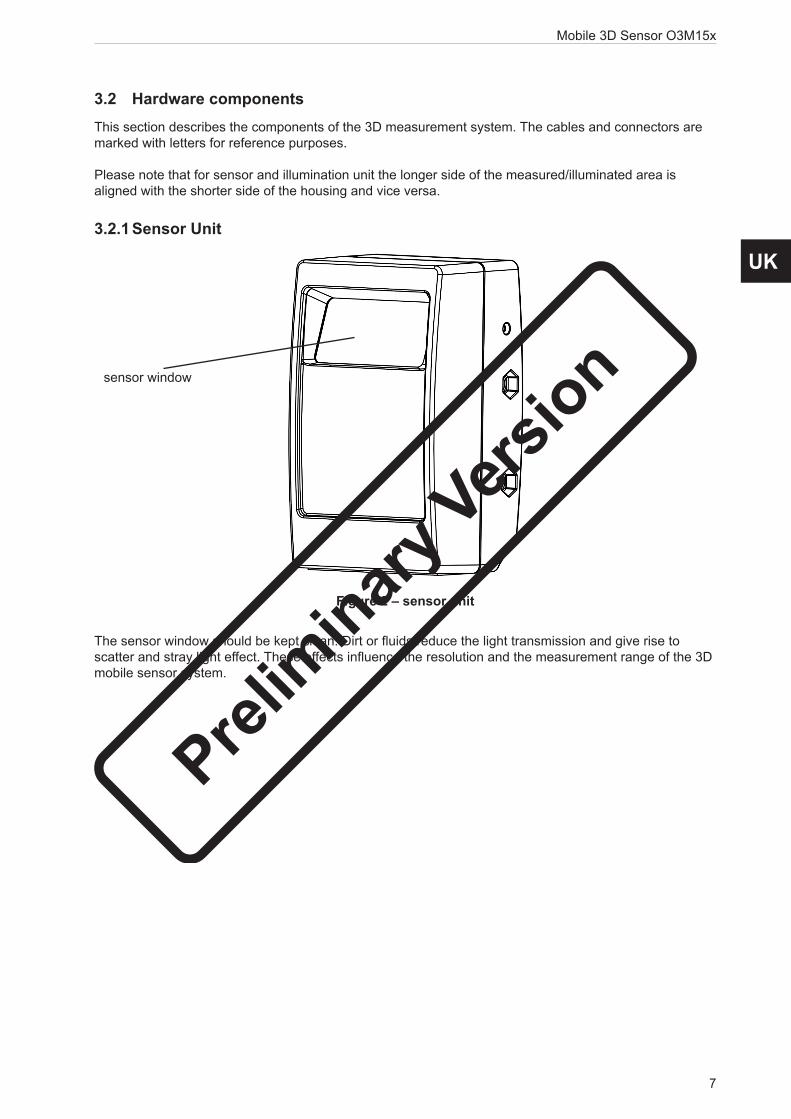
3.2.1 Sensor Unit
Figure 2 – sensor unit
The sensor window should be kept clean. Dirt or fluids reduce the light transmission and give rise to scatter and stray light effect. These effects influence the resolution and the measurement range of the 3D mobile sensor system .
sensor window
Prelim
inary Vers
ion
Mobile 3D Sensor O3M15x
8
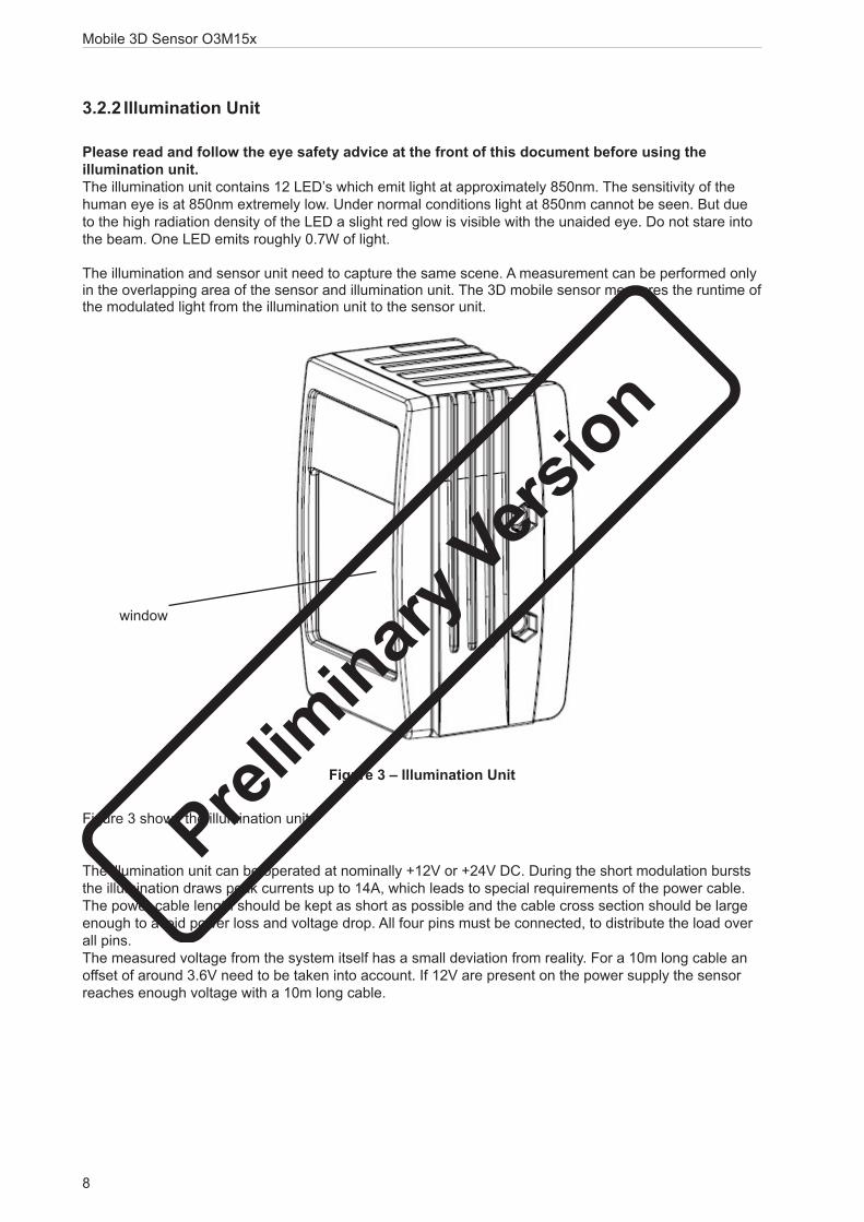
3.2.2 Illumination Unit
Please read and follow the eye safety advice at the front of this document before using the illumination unit. The illumination unit contains 12 LED’s which emit light at approximately 850nm . The sensitivity of the human eye is at 850nm extremely low . Under normal conditions light at 850nm cannot be seen . But due to the high radiation density of the LED a slight red glow is visible with the unaided eye . Do not stare into the beam . One LED emits roughly 0 .7W of light .
The illumination and sensor unit need to capture the same scene . A measurement can be performed only in the overlapping area of the sensor and illumination unit . The 3D mobile sensor measures the runtime of the modulated light from the illumination unit to the sensor unit .
Figure 3 – Illumination Unit
Figure 3 shows the illumination unit:
The illumination unit can be operated at nominally +12V or +24V DC . During the short modulation bursts the illumination draws peak currents up to 14A, which leads to special requirements of the power cable . The power cable length should be kept as short as possible and the cable cross section should be large enough to avoid power loss and voltage drop . All four pins must be connected, to distribute the load over all pins . The measured voltage from the system itself has a small deviation from reality . For a 10m long cable an offset of around 3 .6V need to be taken into account . If 12V are present on the power supply the sensor reaches enough voltage with a 10m long cable .
window
Prelim
inary Vers
ion

9
Mobile 3D Sensor O3M15x
UK
3.2.3 Power supplyA power supply (12/24V DC) need to be provided by the user . The user is responsible for ensuring electrical safety . Adequate fuses should be used to protect against overload . Power cables should be of adequate cross section to reduce the voltage drop along long connections . Colouring schemes of wires may be non-standard and vary . Therefore always check manuals and data sheets before connecting devices .
3.2.4 PC or similar deviceA PC or similar electronic device is able to gather data from the 3D sensor and to display/control and/or store the 3D data . One free Ethernet connector is required (minimum 100MBit, preferably Gigabit Ethernet) which needs to be set to the IP address 192 .168 .1 .X . The X can be any number between 2 and 255 . A direct peer-to-peer connection is recommended . If the sensor is used within a network errors may occur. It is recommended to configure firewalls for the used UDP Port.
3.2.5 Cable connectionsThe following cables are required:
1) Ethernet cable2) MCI cable 3) Power cable (Illumination Unit)4) Power/CAN cable (Sensor Unit)
Connecting order: Sensor with its power/CAN cable, Illumination with its power cable, Sensor with Illumination via MCI cable, Sensor with the Ethernet cable, PC with the Ethernet cable, Optional: CAN module with the CAN cable
Connect at last the Mobile Sensor System with the power supply . All connectors are coded they cannot be connected in the wrong way .
Prelim
inary Vers
ion

Mobile 3D Sensor O3M15x
10
4 Technical Data4.1 Sensor Unit
4.1.1ElectricalspecificationInput voltage 9 . .32V dc (nominal 12V/24V)Current consumption sensor Max . 400mA
4.1.2 Technical data
Temperature range -40° - 85°C (tbc)Sensor resolution (Pixel) 64 horizontal x 16 verticalNominal field of view (H X V) 70° x 23°Modulation frequencies 5 .2 – 8 .8 MHzFrame rate 25 HzEthernet IP address Sensor: 192 .168 .1 .1 UDP
4.1.3 ConnectorsThe sensor subsystem has three connectors, shown in DRW_CAM, Details X,Y,Z: X) Power Y) Ethernet Z) MCI Cable
4.1.4 DimensionsPlease see DRW_CAM
Prelim
inary Vers
ion

11
Mobile 3D Sensor O3M15x
UK
4.2 Illumination Unit
4.2.1ElectricalspecificationsInput voltage 9 . .32V DC (nominal 12V/24V)Current consumption typical values for 1250µs/50µs integration
times and 25Hz frame rate Iavg<2,5AIpeak<14A
To minimise voltage drop and power loss along the cable please keep the power cable as short as possible and always connect all pins of the power connector and power cable (see section DRW_ILU for pinout) . The measured voltage from the system itself has a small deviation from reality . For a 10m long cable an offset of around 3 .6V need to be taken into account . If 12V are present on the power supply the sensor reaches enough voltage with a 10m long cable .
4.2.2 Technical data Temperature range -40° - 85°C (tbc)Nominal field of view (H X V) 70° x 25°Modulation frequencies 5 .2 – 8 .8 MHzFrame rate <25 Hz
4.2.3OpticalSpecificationsMean wavelength at 25°C 850 nm
4.2.4 ConnectorsThe illumination subsystem has two connectors, shown in DRW_ILU, details X, Y:
• 12/24V DC power supply• MCI (modulation and communication signal)
For pin assignment see DRW_ILU
4.2.5 DimensionsPlease see DRW_ILU .
Prelim
inary Vers
ion

Mobile 3D Sensor O3M15x
12
5 Application Hints5.1 Installation of SystemThe O3M15x mobile 3D sensor is operated as a system together with the O3M950 illumination unit .
During installation note the following:►► Operate sensor and illumination unit in combination.►► Install sensor and illumination unit between 0 and 2.80 m apart. It is recommended to mount sensor and illumination directly next to each other looking in the same direction . By this an overlapping of the lighting area of the illumination and the field of view of the sensor can be guaranteed over the whole measurement range . Only if diffuse optical disturbances (e .g . smoke, dust clouds, water spray, very dense fog) are expected, a separation will help the visibility of the sensor in this case . Due to the separation of light source and sensor, direct back scattering effects can be reduced . This is similar to fog lights in a car .►► Select the matching MCI connection cable depending on the distance.►► Use cables with strain relief.►► Keep the area illuminated by the illumination unit free from any obstructions in a close range (up to 50 cm). This prevents direct reflexes back to sensor which otherwise can result in wrong measurement results of the sensor .
5.1.1 Choosing the right mounting positionFor choosing the right mounting position of the system it is essential to define, which area should be within the field of view of the sensor. In general, two cases can be distinguished:
– Forward looking: This mounting position is characterised by a pitch angle of close to 0° (maximum +/- ½ of vertical opening angle) . Therefore it allows the sensor to view the full measurement range close to the ground, enabling to detect objects like persons or vehicles. Close to the sensor the field of view is limited . If objects directly close to sensor shall also be detected, the system should be mounted at a height between 0 .8m and 1 .5m .
– Downward looking: This positioning is characterised by a high mounting and a downward viewing (pitch angle > + ½ of vertical opening angle and < 90° minus ½ of vertical opening angle) . Therefore it maximises the viewing area close to the sensor . However, depending on the height, the foresight may be restricted to a smaller area since the sensor is essentially looking to the ground . In order to keep a decent viewing area, the height of mounting should be maximised within the restraints of the set-up .
5.2 Influence of environmental conditions on sensing principleThe measurement principle is based on the 3D-Time of Flight (ToF) Photonic Mixer Device (PMD) technology . This basically means, that the outgoing infrared light of the illumination is modulated with a carrier frequency, while at the solid state receiver (imager) in the sensor the phase shift of the carrier is measured . This allows to capture 1024 distance information at the same time at high measurement frequencies (up to 50Hz) . Integrated into the imager is a special circuit called Surpression of Backlight Illumination, which reduces the influence of other light sources (e.g. the sun) not modulating with the used frequencies and greatly increases the dynamic range of the system .
5.2.1 Ambient light conditionsDue to the active lighting, maximum system performance is in darkness . However the system also works in any outdoor ambient light conditions up to bright sunlight (~120klux) . Direct sunlight on the target results in an increased noise level in the measurement and therefore in a decreased signal to noise ratio . This means that the distance values are noisier and the measurement range is decreased .Due to the measurement principle, the sensor is less sensitive to direct sunlight into the optic (e .g . in sun low on the horizon situations) than standard 2D sensors . Only the part directly focussing on the sun will result in invalid pixels while otherwise in the scene the sensor will keep measuring correct distances .
Prelim
inary Vers
ion

13
Mobile 3D Sensor O3M15x
UK
5.2.2 Precipitation (rain, snow)The sensing principle is insensitive to precipitation . Only in case of very dense snowfall or torrential rainfall, the measurement range will be decreased .
5.2.3 Water on sensor front screenSince the O3M is an optical system, water drops on the sensor front screen can lead to blurring . This may result in a significant increase of the size of 3D objects and therefore lead to false detections. It is advised to mount the sensor in a way that water on the front screen is prohibited .
5.2.4 Diffuse optical disturbances (dust clouds, smoke, water spray, dense fog etc.)Since the O3M is an optical system it is influenced by diffuse optical disturbances like smoke, dust clouds, fine water spray or dense fog. As a rule of thumb for assessing the application you can compare it with your visual impression of the scenery . The sensor will not be able to see more than the human eye . Please refer to the “Spray Detection” filter for using an automatic detection of such disturbances.
5.2.5 Multi path propagationSince the sensor is based on an optical ToF principle there may occur in certain circumstances multi path propagation issues . This means, that the modulated infrared light emitted by the illumination unit is mirrored by some surface (e .g . mirrors, glas surfaces, polished metal surfaces) . Therefore, the object to be measured is not only illuminated by light on the direct path but also by light coming from a different path (which is longer than the direct path due to the reflection). This may result in distance measurements slightly further than it should be . This effect is more pronounced in tight surroundings, where such surfaces close to the system do occur .
5.3 Special features of the SensorSome special features are implemented in the sensor . They are described in the following:
5.3.1 Window heatingThe sensor front screen has an integrated window heating for de-fogging . The heating function is activated by a setting an on-temperature for heater (window heating is activated, if temperature falls below this value) . The value can be set by using the Vision Assistant PC SW Tool in the device settings .
5.3.2ConfigurablefilteronpixeldataIt is possible to change the filtering of the 3D data before it is computed for the functional output. The filter removes pixels with high distance noise. It is possible to choose between four pre-defined settings. Low filter settings will result in more valid pixels even if data is noisier. Strong filter settings will result in less valid pixels, but these pixels have a higher accuracy . The filter value can be set by using the Vision Assistant PC SW Tool in the application settings under image settings (“Noise reduction filter”). For most applications it is recommended to use the default setting “medium” or the “strong” setting .
5.3.3 Spray detectionThe sensor features a detection algorithm based on the 3D pixel data to identify diffuse optical disturbances (e.g. dust clouds, smoke, fine water spray, dense fog). This filter will change the availability of the system if such a disturbance is detected. The filter can be set to different settings with the Vision Assistant PC SW Tool in the application settings under image settings .
5.3.4UserdefinedworldcoordinatesystemThe sensor features a configurable world coordinate system. By this, the reference point for all outputs can be shifted from the sensor to a point, relevant for the application . In addition, the angles of the mounting can be taken into account .The world coordinate system should be defined in a way, that the origin is moved to the ground and the
Prelim
inary Vers
ion

Mobile 3D Sensor O3M15x
14
pitch angle of the mounting is corrected, so that z points upward (indicating height above ground in the results), while x points forward (positive values meaning distance) . Since this is a right handed coordinate system, y is pointing to the left (seen from the sensor) .If for example the sensor is mounted on top of a vehicle, it is advisable to move the origin to the ground in the middle of the vehicle (in y-direction) and to the foremost point of the bumper . The resulting output values can directly be used in a controller without further conversions .The setting of the user defined world coordinate system can easily be done by help of the Vision Assistant PC SW tool under calibration settings .
5.4 Usage of multiple sensorsAs a result of the operating principle of the system, it is possible to disturb one system by the modulated light of another, if they stare against each other or look in the same area . To minimize such effects, different measures are taken . The system randomly changes between different modulation frequency, which means that the probability of disturbing is greatly reduced . In addition disturbances are detected, so that they will not result in wrong distance values .
Prelim
inary Vers
ion

15
Mobile 3D Sensor O3M15x
UK
6 Downloading program files and system configuration6.1 Downloading program files processThe Mobile Sensor is delivered by default with one specific algorithm or application according to the order number .By downloading a program file from the homepage of the mobile sensor it could be possible to update the application to a newer version or to change the application . This update could be limited by the order number of the sensor. For the link to the program files see also chapter ( 2 .3 Available Software)For further instructions on how to update the sensor with the ifm vision assistant and for a step by step guide please refer to the [programming guide]If you need to create your own diagnosis test equipment that shall download the software to the sensor, please refer to the chapter (6 .3 .3 Diagnosis)
6.2 Configuration parametersThe Mobile Sensor is delivered by default with a set of reasonable parameter settings to control the functionality . These are the so called “customer parameters” .The parameters and their default settings for the O3M150 variant (respectively standard parameters for O3M151 variants) are listed in the chapter (4 .2 .1 List of configuration parameters) . For the parameter descriptions of the embedded functions of the O3M151 please refer to the corresponding function descriptions .The customer parameters could be changed and adjusted according to the application and usage of the sensor . The most intuitive way for changes is the usage of the ifm vision assistant . For further instructions on how to change the configuration parameters with the ifm vision assistant and for a step by step guide please refer to the programming guide of the Vision Assistant software .If you need to create your own diagnosis test equipment that shall update the configuration parameters in the sensor, please refer to the chapter (6 .3 .3 Diagnosis) .
Prelim
inary Vers
ion

Mobile 3D Sensor O3M15x
16
6.2.1ListofconfigurationparametersThe list of configuration parameters could change over. Please check the version of the sensor software to match the version of this operating instruction manual .
Name Value TypeArray-Length Min Max Description Vision Assistant
CycleTime 40 uint8 1 20 40
Internal cycle time of the sensor (20ms/30ms/40ms) . Every cycle time a new 3D image is captured and processed .
Application -> Image Settings -> Frame Rate (value as frequency instead of cycle time)
BeginHeatingTemperature 5 sint8 1 -128 127
Temperature at which the sensor window heating is turned on (in °C)
Device Settings -> Window Heating On Temperature
StopHeatingTemperature 8 sint8 1 -128 127
Temperature at which the sensor window heating is turned off (in °C) . Should be higher than turn on with hysteresis .
Is set by the system automatically as Begin Heating Temperature + 3°C
CANBaudrate 250000 uint32 1 125000 1000000
CAN Baudrate of the sensor . Possible values 125kbs 250kbs 500kbs 1000kbs CAN -> Baudrate
MasterSlaveConfiguration 0 uint8 1 0 8
If multiple sensor are used with overlapping viewing areas and on the same CAN network they can be synchronized with this parameter . Not supported in firmware at SOP. Will be made available by firmware update .
Device Settings -> Synchronisation of multiple sensors
CANProtocol 0 uint8 1 0 1CAN protocol: 0 = J1939, 1 = CANopen CAN -> CAN Protocol
CANopenNodeAddress 10 uint8 1 1 127 CANopen Node value CAN -> Node ID
CANOutputCycleModulo 1 uint8 1 1 3
Defines the the cycletime of can messages: every n-th sensor cycle can messages are sent . With this setting the CAN bus load can be limited .
CAN -> Output Cycle Modulo
J1939SourceAddress 239 uint8 1 1 253 J1939 source address CAN -> Source Address
Ipv4AddressSensor 192 168 1 1 uint8 4 0 255 Ipv4 address of sensor Ethernet -> IP address
SubnetMask255 255 255 0 uint8 4 0 255 Subnet mask of sensor Ethernet -> Subnet Mask
Ipv4AddressDestination255 255 255 255 uint8 4 0 255
Ipc4AddressDestination of the UDP packets
Ethernet -> IP Destination
destinationUDPPort 42000 uint16 1 0 65535Destination UDP port for the UDP packets Ethernet -> UDP Port
EthernetOutputConfiguration 0 uint8 1 0 1
0 is customer output (up to 6MBit/s), 1 is ifm development debug output (up to 60MBit/s)
Only changeable if used for recording of sequences . Monitor -> Record Options -> Debug Data On/Off
EthernetLoadConfiguration 1 uint8 1 1 4EthernetOutput only every n-th system cycle
PMDExtrCalib_camCal_transX 0 float32 1 -10 10
Position of sensor in world: X translation [m] . Please refer to Manual O3M15x for details .
Calibration -> follow instructions
PMDExtrCalib_camCal_transY 0 float32 1 -10 10
Position of sensor in world: Y translation [m] . Please refer to Manual O3M15x for details .
Calibration -> follow instructions
PMDExtrCalib_camCal_transZ 1 float32 1 -10 10
Position of sensor in world: Z translation [m] . Please refer to Manual O3M15x for details .
Calibration -> follow instructions
PMDExtrCalib_camCal_rotX -1,570796 float32 1 -3,142 3,14159Orientation of sensor in world: X rotation [rad]
Calibration -> follow instructions
PMDExtrCalib_camCal_rotY 1,570796 float32 1 -3,142 3,14159Orientation of sensor in world: Y rotation [rad]
Calibration -> follow instructions
PMDExtrCalib_camCal_rotZ 0 float32 1 -3,142 3,14159Orientation of sensor in world: Z rotation [rad]
Calibration -> follow instructions
Prelim
inary Vers
ion
17
Mobile 3D Sensor O3M15x
UK
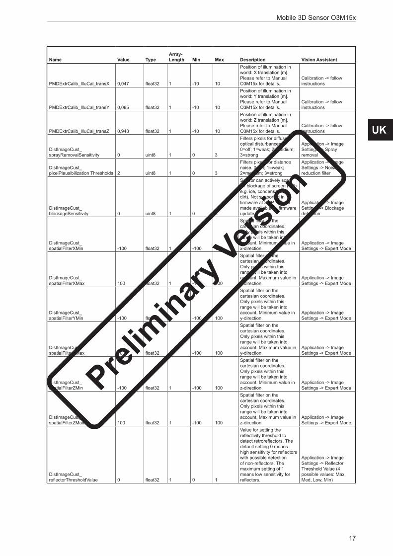
Name Value TypeArray-Length Min Max Description Vision Assistant
PMDExtrCalib_IlluCal_transX 0,047 float32 1 -10 10
Position of illumination in world: X translation [m] . Please refer to Manual O3M15x for details .
Calibration -> follow instructions
PMDExtrCalib_IlluCal_transY 0,085 float32 1 -10 10
Position of illumination in world: Y translation [m] . Please refer to Manual O3M15x for details .
Calibration -> follow instructions
PMDExtrCalib_IlluCal_transZ 0,948 float32 1 -10 10
Position of illumination in world: Z translation [m] . Please refer to Manual O3M15x for details .
Calibration -> follow instructions
DistImageCust_sprayRemovalSensitivity 0 uint8 1 0 3
Filters pixels for diffuse optical disturbances . 0=off; 1=weak; 2=medium; 3=strong
Application -> Image Settings -> Spray removal
DistImageCust_pixelPlausibilization Thresholds 2 uint8 1 0 3
Filters pixels for distance noise . 0=off; 1=weak; 2=medium; 3=strong
Application -> Image Settings -> Noise reduction filter
DistImageCust_blockageSensitivity 0 uint8 1 0 3
Sensor can actively scan for blockage of screen (with e .g . ice, condensation, dirt) . Not supported in firmware at SOP. Will be made available by firmware update .
Application -> Image Settings -> Blockage detection
DistImageCust_spatialFilterXMin -100 float32 1 -100 100
Spatial filter on the cartesian coordinates . Only pixels within this range will be taken into account . Minimum value in x-direction .
Application -> Image Settings -> Expert Mode
DistImageCust_spatialFilterXMax 100 float32 1 -100 100
Spatial filter on the cartesian coordinates . Only pixels within this range will be taken into account . Maximum value in x-direction .
Application -> Image Settings -> Expert Mode
DistImageCust_spatialFilterYMin -100 float32 1 -100 100
Spatial filter on the cartesian coordinates . Only pixels within this range will be taken into account . Minimum value in y-direction .
Application -> Image Settings -> Expert Mode
DistImageCust_spatialFilterYMax 100 float32 1 -100 100
Spatial filter on the cartesian coordinates . Only pixels within this range will be taken into account . Maximum value in y-direction .
Application -> Image Settings -> Expert Mode
DistImageCust_spatialFilterZMin -100 float32 1 -100 100
Spatial filter on the cartesian coordinates . Only pixels within this range will be taken into account . Minimum value in z-direction .
Application -> Image Settings -> Expert Mode
DistImageCust_spatialFilterZMax 100 float32 1 -100 100
Spatial filter on the cartesian coordinates . Only pixels within this range will be taken into account . Maximum value in z-direction .
Application -> Image Settings -> Expert Mode
DistImageCust_reflectorThresholdValue 0 float32 1 0 1
Value for setting the reflectivity threshold to detect retroreflectors. The default setting 0 means high sensitivity for reflectors with possible detection of non-reflectors. The maximum setting of 1 means low sensitivity for reflectors.
Application -> Image Settings -> Reflector Threshold Value (4 possible values: Max, Med, Low, Min)
Prelim
inary Vers
ion

Mobile 3D Sensor O3M15x
18
Name Value TypeArray-Length Min Max Description Vision Assistant
DistImageCust_reflectorCloseRange 1 uint8 1 0 1
The system internally changes the illumination times. For reflectors in close range (<3m) a very short illumination time is necessary . 0 = close reflectors are not expected; 1 = close reflectors are of importance .
Application -> Image Settings -> Reflectors close range
AutoCalibParam_numberOfPatterns 0 uint8 1 0 8
Number of patterns to be used for autocalibration (0,1 : autocalibration disabled) . Specialautocalibration mode for measuring the rotational angles based on reflector targets at defined positions . Number of reflectors used. Should be at least 3 .
Template in Vision Assistant SW will be available with later update .
AutoCalibParam_xPattern 0 float32 8 -30 30
x coordinates [m] of the autocalibration patterns in relation to the defined world coordinate system .
Template in Vision Assistant SW will be available with later update .
AutoCalibParam_yPattern 0 float32 8 -30 30
y coordinates [m] of the autocalibration patterns in relation to the defined world coordinate system .
Template in Vision Assistant SW will be available with later update .
AutoCalibParam_zPattern 0 float32 8 -30 30
z coordinates [m] of the autocalibration patterns in relation to the defined world coordinate system .
Template in Vision Assistant SW will be available with later update .
AutoCalibParam_patternType 0 uint8 8 0 10Type of the autocalibration patterns
Template in Vision Assistant SW will be available with later update .
Prelim
inary Vers
ion

19
Mobile 3D Sensor O3M15x
UK
7 Advanced programmingThis chapter is designated for programmers who want to implement advanced algorithms in a dedicated controller or PLC (here called device) and are not able to use the function block as described in [application guides] . This is the comprehensive description of the interfaces and protocols used by the mobile sensor .
7.1 General declaration
7.1.1 Cycle timeThe sensor captures images with 50Hz/33Hz/25Hz frequency . This frequency can be selected by the user, please see chapter (5 .2 .1 List of configuration parameters) .This frequency also applies for the cycle time on the CAN bus and for the data repetition on Ethernet output . This frequency is also called
- System cycle- CAN cycle- Cycle time
The cycle time can be defined by means of time like 20ms, 30ms, 40ms.
7.1.2 System statesAccording to the current operation mode the system will change the system state . The system state can be inspected
- with the ifm vision assistant or - on the CAN Bus observing the Message “Global_Information” signal “SwCtrl_OpMode” (SAE
J1939)- on the CANOpen bus observing the Object 2201 “Global_Information” SubIndex 3 “SwCtrl_
OpMode” rsp TPDO mapping 1A29- with UDS diagnosis requests (see below)
Table 2: System states
System state Value Definition Description
INIT 0x11
Internal state during startup
Please wait for the RUN state for normal operation .
STARTUP 0x12
Internal state during startup
Please wait for the RUN state for normal operation .
DSP_BOOT 0x13
Internal state during startup
Please wait for the RUN state for normal operation .
SELFTEST 0x14
System is performing selftest during startup
Please wait for the RUN state for normal operation .
WAIT_DSP_BOOTED 0x15
Internal state during startup
Please wait for the RUN state for normal operation .
Prelim
inary Vers
ion

Mobile 3D Sensor O3M15x
20
System state Value Definition Description
PARAMETRIZING 0x17
System is reading Parameters during startup
Please wait for the RUN state for normal operation .
RUN 0x22
Normal operation Normal operation, algorithms are running, illumination is on, CAN- and Ethernet output performing normal according to the configured cycle time
LIMITED_RUN 0x21
Reversible fault with limited impact which could recover .
Internal processes are running, CAN and Ethernet output are produced but limited to some default messagesNo algorithm running .The system tries to recover from this state to normal operation .Diagnosis requests will be processed .
EMERGENCY 0x31
Irreversible error with limited fault impact which could not automatically recover .
Internal processes are running, CAN and Ethernet output are produced but limited to some default messagesNo algorithm running .The system will not recover from this state to normal operation . System must be resetted (e .g . power off and on cycle) to recover .Diagnosis requests will be processed .
SAFE 0x41
Irreversible error with unknown impact which could not recover at all .
No algorithm operating, system tries to prevent further damage, no diagnosis requests will be processed . System should be sent to sales or manufacturer .
7.1.3 Startup of the sensorThe system is performing the following states in this sequence:
- INIT- STARTUP- DSP_BOOT- SELFTEST- WAIT_DSP_BOOTED- PARAMETRIZING- RUN
When reaching the state RUN, the startup is finished.
When the sensor and the illumination are connected for the first time, they will exchange additional data and thus the startup will need more time than during the following startups (up to 20 sec) . This is the so called pairing .
Prelim
inary Vers
ion

21
Mobile 3D Sensor O3M15x
UK
7.1.4 Fault memory and diagnostic error codesThere is a fault memory which stored a certain history of faults . There could be up to 20 entries in the fault memory . These values could be requested by
- Using UDS diagnosis (see below)- On CAN bus (SAE J1939) please use the UDS diagnosis- With CANopen please refer to the object 1003 “Predefined Error Field”
Table 3: List of diagnostic codes
DTC-DFCC
DTC-DFCC TEXT DESCRIPTION RECO-VERAB-LE WI-THOUT REBOOT
0xFE000C CAN_EBS21_TIMEOUT the J1939 signal EBS21 is missing
y
0xFE002C CAN_VDC2_TIMEOUT the J1939 signal VDC2 is missing
y
0xFE004C CAN_TCO1_TIMEOUT the J1939 signal TCO1 is missing
y
0xFE006C PowerSupply_to_high Sensor Power supply is > 32V y0xFE008C PowerSupply_to_low Sensor Power supply is < 9V y0xFE00AC Sensor_InternalPowerSupply_5V9_to_high internal fault y0xFE00CC Sensor_InternalPowerSuppl_5V9_to_low internal fault y0xFE00EC Sensor_InternalPowerSupply_5V0_FER_to_high internal fault y0xFE010C Sensor_InternalPowerSuppl_5V0_FER_to_low internal fault y0xFE012C Sensor_InternalPowerSupply_5V0_FE_to_high internal fault y0xFE020C Sensor_InternalPowerSuppl_5V0_FE_to_low internal fault y0xFE022C Sensor_InternalPowerSupply_5V0_to_high internal fault y0xFE024C Sensor_InternalPowerSuppl_5V0_to_low internal fault y0xFE026C Sensor_InternalPowerSupply_3V3_FER_to_high internal fault y0xFE028C Sensor_InternalPowerSupply_3V3_FER_to_low internal fault y0xFE02AC Sensor_InternalPowerSupply_3V3_to_high internal fault y0xFE02CC Sensor_InternalPowerSupply_3V3_to_low internal fault y0xFE02EC Sensor_InternalPowerSupply_1V8_to_high internal fault y0xFE030C Sensor_InternalPowerSupply_1V8_to_low internal fault y0xFE032C Sensor_InternalPowerSupply_1V8_FeR_to_high internal fault y0xFE040C Sensor_InternalPowerSupply_1V8_FeR_to_low internal fault y0xFE042C Sensor_InternalPowerSupply_1V25_to_high internal fault y0xFE044C Sensor_InternalPowerSupply_1V25_to_low internal fault y0xFE046C Sensor_InternalPowerSupply_1V25_FeR_to_high internal fault y0xFE048C Sensor_InternalPowerSupply_1V25_FeR_to_low internal fault y0xFE04AC Illumination_InternalPowerSupply_3V3_to_high internal fault n0xFE04CC Illumination_InternalPowerSuppl_3V3_to_low internal fault n0xFE04EC Illumination_InternalTemperatur_NoResponse internal fault n0xFE050C Illumination_InternalTemperatur_Analog_Invalid internal fault n0xFE052C Illumination_InternalTemperatur_Digital_Invalid internal fault n0xFE060C Illumination_InternalTemperatur_Inconsistent internal fault n0xFE062C Sensor_FctLimitation_OverTemperatur Sensor temperature > 85°C y
Prelim
inary Vers
ion

Mobile 3D Sensor O3M15x
22
DTC-DFCC
DTC-DFCC TEXT DESCRIPTION RECO-VERAB-LE WI-THOUT REBOOT
0xFE064C Sensor_FctLimitation_UnderTemperatur Sensor temperature < -40°C y0xFE066C Illumination_FctLimitation_OverTemperatur Illumination temperature >
85°Cy
0xFE068C Illumination_FctLimitation_UnderTemperatur Illumination temperature < -40°C
y
0xFE06AC DSP_PARAMETERIZATION_FAILED internal fault y0xFE06CC DSP_NO_IMAGE_DATA internal fault y0xFE072C KP_NVM_E_INTEGRITY_FAILED internal fault y0xFE080C KP_NVM_E_REQ_FAILED internal fault y0xFE082C KP_SCC_DSP_EVENT_INTEGRITY_CHECK internal fault y0xFE084C KP_SCC_UNWRAP_IPC_DEMEVENTS internal fault y0xFE086C KP_SWCTRL_VERSION_COMPATIBILITY_CFG The SW version and/or
parameter data format do not match . An update of program files and configuration data could help . If this problem is persistent please call your vendor or ifm support .
y
0xFE088C KP_MON_TASKMONITORING_FAILED internal fault y0xFE08AC DSP_IPC_RX_TIMEOUT internal fault y0xFE08CC DSP_IPC_RX_CRC internal fault y0xFE08EC DSP_IPC_RX_MSG_CNT internal fault y0xFE090C KP_ILLU_RX_TIMEOUT internal fault y0xFE092C KP_ILLU_RX_CRC internal fault n0xFE0A0C KP_ILLU_RX_MSG_CNT internal fault n0xFE0A2C KP_ILLU_PROTOCOL_ERR internal fault n0xFE0A4C DK_RX_CRC internal fault y0xFE0A8C DSP_RAC_ERROR internal fault n0xFE0AAC DK_MOD_DUTY_CYCLE_BIGGER_THAN_35_
PERCENTinternal fault y
0xFE0ACC DSP_MON_ALGO_TIMING_VIOLATION internal fault y0xFE0AEC DSP_MON_ALGO_ERR internal fault y0xFE0B0C KP_SCC_SYNC_LOST internal fault y0xFE0B2C KP_SWCTRL_WRONG_DSP_STATE_
RECEIVEDinternal fault y
0xFE0C0C DK_MOD_PULSE_LENGTH_BIGGER_THAN_1_5_MS
internal fault y
0xFE0C2C KP_MON_SCC_CYCLE_BEGIN_CHECKPOINT internal fault n0xFE0C4C KP_MON_SCC_CYCLE_SYNC_CHECKPOINT internal fault n0xFE0C6C KP_MON_MAIN_FUNCTION_START_
CHECKPOINTinternal fault n
0xFE0C8C KP_MON_IPC_DATAT_RECEIVED_CHECKPOINT
internal fault n
0xFE0CAC KP_MON_ALGO_START_CHECKPOINT internal fault n0xFE0CCC KP_MON_DSPWATCHDOG_ERROR internal fault n0xFE0CEC KP_IPC_RX_TIMEOUT internal fault n
Prelim
inary Vers
ion

23
Mobile 3D Sensor O3M15x
UK
DTC-DFCC
DTC-DFCC TEXT DESCRIPTION RECO-VERAB-LE WI-THOUT REBOOT
0xFE0D0C KP_IPC_RX_CRC internal fault n
0xFE0D2C KP_IPC_RX_MSG_CNT internal fault n
0xFE0E2C KP_ILLU_PARAM_MISMATCH The SW version and/or parameter data format do not match . An update of program files and configuration data could help . If this problem is persistent please call your vendor or ifm support .
n
0xFE0E4C KP_CAMERA_PARAM_MISMATCH The SW version and/or parameter data format do not match . An update of program files and configuration data could help . If this problem is persistent please call your vendor or ifm support .
y
0xFE0E6C KP_SWCTRL_DSP_NOT_BOOTED internal fault y
0xFE0E8C KP_SWCTRL_PARAMETERIZING_TIMEOUT internal fault y
0xFE0EAC DSP_FHM_PARAM_ERR The SW version and/or parameter data format do not match . An update of program files and configuration data could help . If this problem is persistent please call your vendor or ifm support .
y
0xFE0ECC KP_BLCOM_VERSION_MISMATCH The SW version and/or parameter data format do not match . An update of program files and configuration data could help . If this problem is persistent please call your vendor or ifm support .
y
0xFE0EEC KP_BLCOM_INTEGRITY_FAILED The SW version and/or parameter data format do not match . An update of program files and configuration data could help . If this problem is persistent please call your vendor or ifm support .
y
0xFE100C DK_OVERVOLTAGE_ILLU3 internal fault y
Prelim
inary Vers
ion

Mobile 3D Sensor O3M15x
24
DTC-DFCC
DTC-DFCC TEXT DESCRIPTION RECO-VERAB-LE WI-THOUT REBOOT
0xFE102C DK_UNDERVOLTAGE_ILLU3 internal fault y
0xFE104C DK_ROM_CRC_INVALID The SW version and/or parameter data format do not match . An update of program files and configuration data could help . If this problem is persistent please call your vendor or ifm support .
y
0xFE106C DK_IO_PIN_INVALID internal fault y
0xFE108C DK_OVERVOLTAGE_ILLU2 internal fault y
0xFE10AC DK_OVERVOLTAGE_ILLU1 internal fault y
0xFE10CC DK_OVERCURRENT_ILLU2 internal fault y
0xFE10EC DK_OVERCURRENT_ILLU1 internal fault y
0xFE110C DK_UNDERVOLTAGE_ILLU2 internal fault y
0xFE112C DK_NO_MOD_DETECTED internal fault y
0xFE120C DK_UNDERVOLTAGE_ILLU1 internal fault y
0xFE122C DK_KL15_TOO_HIGH illumination power supply > 32V
y
0xFE124C DK_KL15_TOO_LOW illumination power supply < 9V y
0xFE126C DSP_CPLD_FRAME_MISSING internal fault y
0xFE12AC KP_IPC_COMPATIBILITY_VERSION The SW version and/or parameter data format do not match . An update of program files and configuration data could help . If this problem is persistent please call your vendor or ifm support .
n
Prelim
inary Vers
ion

25
Mobile 3D Sensor O3M15x
UK
DTC-DFCC
DTC-DFCC TEXT DESCRIPTION RECO-VERAB-LE WI-THOUT REBOOT
0xFE12CC KP_IPC_TESTVERSION_FLASHED The SW version and/or parameter data format do not match . An update of program files and configuration data could help . If this problem is persistent please call your vendor or ifm support .
n
0xFE12EC KP_SWCTRL_TESTVERSION_FLASHED The SW version and/or parameter data format do not match . An update of program files and configuration data could help . If this problem is persistent please call your vendor or ifm support .
y
0xFE130C KP_HEAT_HEATING_TIME_EXCEEDED internal fault n
0xFE132C KP_ICOM_DK_NOT_CONNECTED internal fault n
0xFE200C KP_ICOM_CALIBRATION_MISMATCH The SW version and/or parameter data format do not match . An update of program files and configuration data could help . If this problem is persistent please call your vendor or ifm support .
n
0xFE202C KP_NVM_CFG_MISMATCH The SW version and/or parameter data format do not match . An update of program files and configuration data could help . If this problem is persistent please call your vendor or ifm support .
y
0xFE204C KP_OPAR_CRC_MISMATCH The SW version and/or parameter data format do not match . An update of program files and configuration data could help . If this problem is persistent please call your vendor or ifm support .
y
0xFE206C KP_OPAR_VERSION_MISMATCH The SW version and/or parameter data format do not match . An update of program files and configuration data could help . If this problem is persistent please call your vendor or ifm support .
n
Prelim
inary Vers
ion

Mobile 3D Sensor O3M15x
26
DTC-DFCC
DTC-DFCC TEXT DESCRIPTION RECO-VERAB-LE WI-THOUT REBOOT
0xFE208C KP_PPAR_CRC_MISMATCH The SW version and/or parameter data format do not match . An update of program files and configuration data could help . If this problem is persistent please call your vendor or ifm support .
y
0xFE20AC KP_PPAR_VERSION_MISMATCH The SW version and/or parameter data format do not match . An update of program files and configuration data could help . If this problem is persistent please call your vendor or ifm support .
y
0xFE20CC KP_CPAR_CRC_MISMATCH The SW version and/or parameter data format do not match . An update of program files and configuration data could help . If this problem is persistent please call your vendor or ifm support .
y
0xFE20EC KP_CPAR_VERSION_MISMATCH The SW version and/or parameter data format do not match . An update of program files and configuration data could help . If this problem is persistent please call your vendor or ifm support .
y
0xFE210C KP_MCU_E_OTP_NOT_PROGRAMMED The SW version and/or parameter data format do not match . An update of program files and configuration data could help . If this problem is persistent please call your vendor or ifm support .
n
0xFE220C KP_ICOM_DK_NO_APPLICATION The SW version and/or parameter data format do not match . An update of program files and configuration data could help . If this problem is persistent please call your vendor or ifm support .
n
0xFE222C DSP_AUTOCALIB_INVALID The SW version and/or parameter data format do not match . An update of program files and configuration data could help . If this problem is persistent please call your vendor or ifm support .
y
Prelim
inary Vers
ion

27
Mobile 3D Sensor O3M15x
UK
DTC-DFCC
DTC-DFCC TEXT DESCRIPTION RECO-VERAB-LE WI-THOUT REBOOT
0xFE224C DSP_CPAR_INVALID The SW version and/or parameter data format do not match . An update of program files and configuration data could help . If this problem is persistent please call your vendor or ifm support .
y
0xFE226C DSP_OPAR_INVALID The SW version and/or parameter data format do not match . An update of program files and configuration data could help . If this problem is persistent please call your vendor or ifm support .
y
0xFE228C DSP_MPAR_INVALID The SW version and/or parameter data format do not match . An update of program files and configuration data could help . If this problem is persistent please call your vendor or ifm support .
y
0xFE22AC KP_MON_WATCHDOG_TEST_ERROR internal fault y
0xFE22CC DSP_DK_MPAR_INVALID The SW version and/or parameter data format do not match . An update of program files and configuration data could help . If this problem is persistent please call your vendor or ifm support .
y
0xFE22EC KP_IPC_COMPATIBILITY_VARIANT The SW version and/or parameter data format do not match . An update of program files and configuration data could help . If this problem is persistent please call your vendor or ifm support .
n
0xFE230C KP_SWCTRL_VARIANT_COMPATIBILITY_CFG The SW version and/or parameter data format do not match . An update of program files and configuration data could help . If this problem is persistent please call your vendor or ifm support .
y
Prelim
inary Vers
ion
Mobile 3D Sensor O3M15x
28
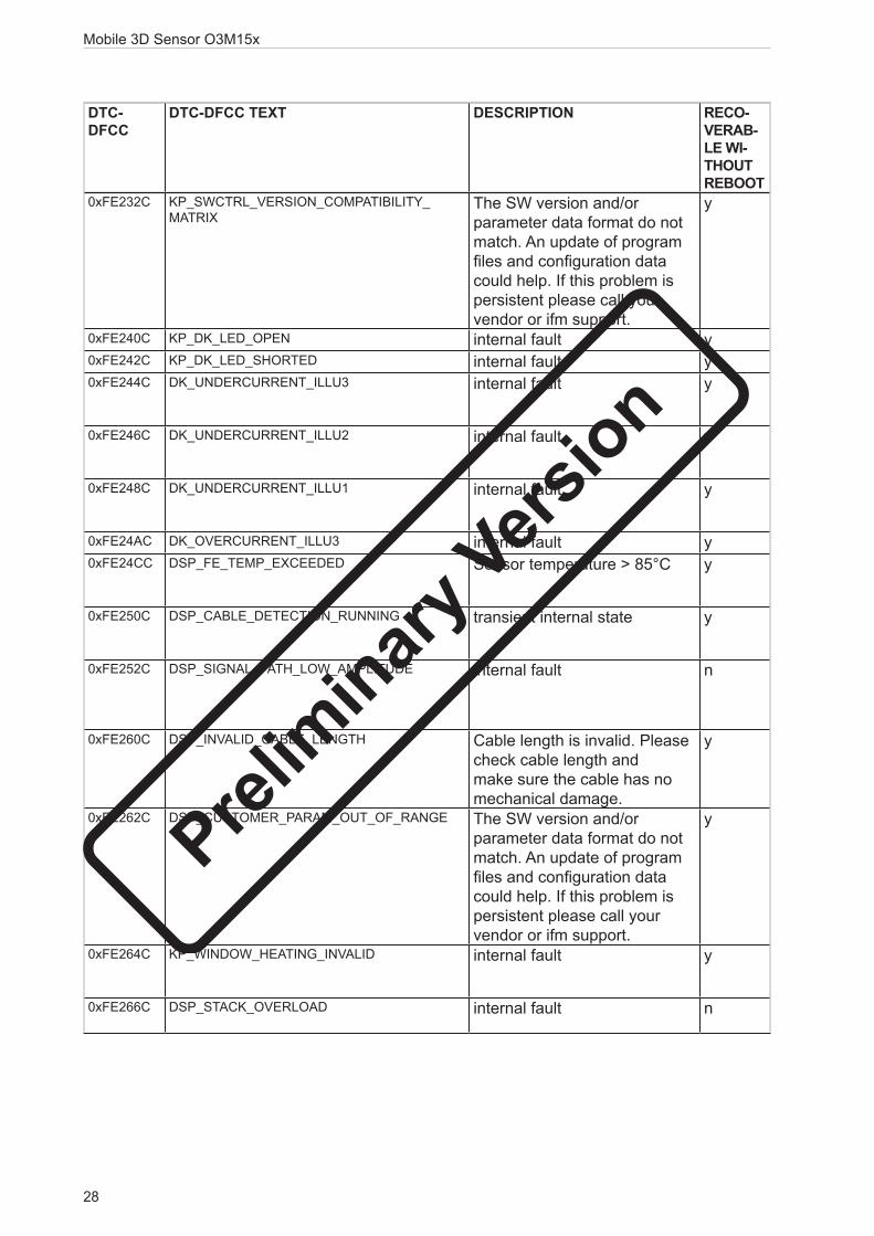
DTC-DFCC
DTC-DFCC TEXT DESCRIPTION RECO-VERAB-LE WI-THOUT REBOOT
0xFE232C KP_SWCTRL_VERSION_COMPATIBILITY_MATRIX
The SW version and/or parameter data format do not match . An update of program files and configuration data could help . If this problem is persistent please call your vendor or ifm support .
y
0xFE240C KP_DK_LED_OPEN internal fault y0xFE242C KP_DK_LED_SHORTED internal fault y0xFE244C DK_UNDERCURRENT_ILLU3 internal fault y
0xFE246C DK_UNDERCURRENT_ILLU2 internal fault y
0xFE248C DK_UNDERCURRENT_ILLU1 internal fault y
0xFE24AC DK_OVERCURRENT_ILLU3 internal fault y0xFE24CC DSP_FE_TEMP_EXCEEDED Sensor temperature > 85°C y
0xFE250C DSP_CABLE_DETECTION_RUNNING transient internal state y
0xFE252C DSP_SIGNAL_PATH_LOW_AMPLITUDE internal fault n
0xFE260C DSP_INVALID_CABLE_LENGTH Cable length is invalid . Please check cable length and make sure the cable has no mechanical damage .
y
0xFE262C DSP_CUSTOMER_PARAM_OUT_OF_RANGE The SW version and/or parameter data format do not match . An update of program files and configuration data could help . If this problem is persistent please call your vendor or ifm support .
y
0xFE264C KP_WINDOW_HEATING_INVALID internal fault y
0xFE266C DSP_STACK_OVERLOAD internal fault n
Prelim
inary Vers
ion

29
Mobile 3D Sensor O3M15x
UK
DTC-DFCC
DTC-DFCC TEXT DESCRIPTION RECO-VERAB-LE WI-THOUT REBOOT
0xFE268C KP_CPAR_INVALID The SW version and/or parameter data format do not match . An update of program files and configuration data could help . If this problem is persistent please call your vendor or ifm support .
n
0xFE26AC KP_APPL_INVALID The SW version and/or parameter data format do not match . An update of program files and configuration data could help . If this problem is persistent please call your vendor or ifm support .
n
6.2 CAN bus interfaceThe mobile sensor has a physical CAN interface . It can use the SAE J1939 or the CANopen protocols .According to the configuration parameter “CANProtocol” (see chapter 5 .2 Configuration parameters) it is possible to choose one of these two protocols . Independent of usage of SAEJ1939 or CANopen it is always possible to start an UDS session . Some of the diagnosis services are restricted for ifm production use only . They are secured by the so called supplier mode .
6.2.1 CANopen list of objectsThe CANopen objects are defined by means of an EDS file. For each variant of the sensor there is a specific EDS file available. Please refer to (EDS file)The following list shows the objects common for all sensor variants .
Please consider the following additional notes about the EDS file and object definitions:
Object 1000 DeviceType:Fixed to “0” (Zero) this EDS file does not follow a CANopen profile
Object 1003 Predefined Error Field:Index 01: Number of Errors is defined according the size of the error memory in the diagnosis.
Object 1008 Manufacturer Device Name:(No Index) is filled at runtime with the article number of the sensor.Device is Sensor: O3M150Device is Smart Sensor: O3M151
Object 1009 Manufacturer Hardware Version:(No Index) is filled at runtime with the HW Version of the sensor
Object 100A Manufacturer Software Version:(No Index) is filled at runtime with the Software version number and variant of the sensor with <Major> .<Minor> .<Patchlevel> <Variant>
Prelim
inary Vers
ion

Mobile 3D Sensor O3M15x
30
Object 1010 Store Parameter Field:Index 02: Save all Parameters: currently not supported
Object 1011 Restore Default Parameters:Index 02: Restore all Default Parameters: currently not supported
Object 1018 Identity Object:Index 02: Vendor ID is 0x0069666D, this is the ID for ifm electronic, is fixedIndex 03: Product Code:O3M150: 0x0020 0010O3M151: 0x0020 0011Index 04: Revision Number: is filled at runtime with 0x00 <Major number> <Minor number> <Patch Level> of the SW Version .Index 05: Serial number: is filled at runtime with the serial number of the sensor.
Objects 1400-1402, 1600-1602: Index02 Transmission Type: 254 (Manufacturer defined):The mobile sensor is typically running with internally defined time/frequencyThus it will send out the data (TPDOs) as available, with cycle time of 20ms, 30ms, 40ms or multiple times: double or three times the cycle time .
Objects 1800-18** Transmit PDO Communication Parameter:There are TPDO parameters defined in such a way that the sensor will immediately start to send out data when the communication state is set to “Operational” . According to the function of the sensor, there are TPDO parameters defined such that for all “real world object” exists a TPDO definition.The sensor sends out only 4 objects in default configuration. For the other TPDOs the settings are such that they are marked as invalid . Bit 31(valid bit) is set to “1” .If these Objects are requested by a Network Master/Configuration Master the according COB ID has to be set accordingly, especially the valid bit has to be set to “0” .
Object 2201: Global_InformationThis object contains global status information of the sensor .SubIndex 1: GLOB_master_timeThis subindex contains a timestamp of the system and could be used for sorting the “real world object” information according to this time stamp .SubIndex 2: GLOB_sensor_availableThis subindex contains summary information about the quality of the measurement Values are bitwise coded and can be coded sumulataneously by bitwise “OR” as follows:
Table 4: Values for GLOB_sensor_available
Bit CommentBIT_INTERFERENCE_DETECTED (1u)
The system detected that it is blinded by another illumination that sends out light with the same frequency . Should occur only for one or two system cycles and disappear because of frequency hopping .
BIT_SPRAY_DETECTION (2u) The system detected that it’s measurement is disturbed by spray . Should disappear when the spray is removed .
BIT_TRACKING_ERROR (4u) The system has problems to track an real world object over time or in the area .
BIT_INVALID_CAM_ORIENTATION (8u)
The system detected that the extrinsic calibration is not plausible, e .g . by ground detection . Please check the customer parameters related to the mounting of the sensor .
BIT_SIGNAL_PATH_MONITORING (16u)
The system found a problem during signal path monitoring . If this bit is set permanently then please check the MKC cabling of the sensor and illumination .
BIT_INTERNAL_ERROR (32u) The system detected an internal error during processing the function or processing the distance image . Please try to reboot the systems . If this error persists please contact ifm support
Prelim
inary Vers
ion

31
Mobile 3D Sensor O3M15x
UK
SubIndex 3: SwCtrl_OpModeThis subindex contains information about the system status or operational mode . Values could be as follows:
Table 5: Values for SwCtrl_OpMode
Value Name Comment0x11 INIT first state in boot process, please wait.0x12 STARTUP second state in boot process, please wait .0x13 DSP_BOOT third state in boot process, please wait .0x14 SELFTEST forth state in boot process, please wait .0x15 WAIT_DSP_BOOTED fifth state in boot process, please wait.0x17 PARAMETRIZING sixth state in boot process, please wait .0x21 LIMITED_RUN system detected recoverable internal state . Please check the
error memory . Usually the system could recover from this state to RUN mode if the source of the error is removed . If this state is persistent, please contact your ifm support .
0x22 RUN normal operating state .0x31 EMERGENCY system detected non recoverable internal state . Please check
the error memory . System can only recover from this mode if the source of the error is removed and the system is rebooted . If this state is persistent, please contact your ifm support .
SubIndex 4: Global_Information_cntThis subindex is used to synchronize all associated objects belonging to one frame . All messages have at least one subindex named “*_cnt” . Two consecutive frames do have different counter values, meaning the subindexes “*_cnt” are different for consecutive frames and are the same for one frame .
Object 2210: SyncMsg SubIndex 1: MasterTime_LastTxTimeStampThis is the system master time and could be used to synchronize the system with other types of sensors to implement time synchronized information .
Prelim
inary Vers
ion

Mobile 3D Sensor O3M15x
32
6.2.2 SAE J1939 list of messagesThe messages and signals of the SAE J1939 protocol are defined by means of a DBC file. For each variant of the sensor there is a specific DBC file available. Please refer to (DBC file)The following table shows the signals common for all sensor variants .
Table 6: list of J1939 signals common for all variants
Name Message Start bit
Length [Bit]
Value Type
Factor Offset Minimum Maximum Unit SPN
GLOB_master_time
Global_Information
0 32 Unsigned 1 0 0 4,29E+14 µs 523000
GLOB_sensor_available
Global_Information
32 8 Unsigned 1 0 0 255 enum 523001
Global_Information_cnt
Global_Information
46 2 Unsigned 1 0 0 3 523003
SwCtrl_OpMode Global_Information
40 6 Unsigned 1 0 0 63
Mastertime_LastTxTimeStamp
SyncMsg 0 32 Unsigned 1 0 0 4,29E+14 us 523500
For the meaning and valid values please refer to the chapter (6 .2 .1CANopen list of objects) . Same object name in CANopen and in SAE J1939 have the same meaning . Please see tables Table 4: Values for GLOB_sensor_available and Table 5: Values for SwCtrl_OpMode .
Prelim
inary Vers
ion

33
Mobile 3D Sensor O3M15x
UK
6.3 System diagnosis and diagnostic servicesFor reading and writing diagnostic information and for calling the diagnosis services, the mobile sensor uses the UDS protocol as defined by ISO 14229 .
6.3.1 OverviewThe following table lists all the Diagnosis services. The predefined adressing mode and the response behaviour are marked with „X“ . In case that services are available in the Diagnosis instances, that differ from the presettings, then this is marked with “(*)” and will be described in the according diagnosis instance .
Table 7: list of diagnostic services
SID Name phys req
func req
phys pos resp
func pos resp
SPRMIB phys req
SPRMIB func req
multi periodic required
$10 DiagnosticSessionControl X X X X 0/1 0/1 X$11 EcuReset X X X X 0/1 0/1$14 ClearDiagnosticInformation X X X X$19 ReadDtcInformation - Report DTC by
status maskX X X X 0/1 0/1
$19 ReadDtcInformation - Report DTC extended data record by DTC number
X X X X 0/1 0/1
$19 ReadDtcInformation - Report number of DTC by status mask
X X X X 0/1 0/1
$19 ReadDtcInformation - Report supported DTC
X X X X 0/1 0/1
$19 ReadDtcInformation - ReportDTCFaultDetectionCounter
X X X X 0/1 0/1
$19 ReadDtcInformation - ReportDtcSnapshotIdentification
X X X X 0/1 0/1
$19 ReadDtcInformation - ReportFirstConfirmedDTC
X X X X 0/1 0/1
$19 ReadDtcInformation - ReportFirstTestFailedDTC
X X X X 0/1 0/1
$19 ReadDtcInformation - ReportMostRecentConfirmedDTC
X X X X 0/1 0/1
$19 ReadDtcInformation - ReportMostRecentTestFailedDTC
X X X X 0/1 0/1
$22 ReadDataByIdentifier X X(*) X X(*)$23 ReadMemoryByAddress X X X X$27 SecurityAccess - Request seed X X X X 0/1 0/1$27 SecurityAccess - Send key X X X X 0/1 0/1$28 CommunicationControl X X X X 0/1 0/1$2E WriteDataByIdentifier X X X X$31 RoutineControl - Start routine X X X X 0/1 0/1$34 RequestDownload X X X X$36 TransferData X X(*) X X(*)$37 RequestTransferExit X X X X$3D WriteMemoryByAddress X X X X$3E TesterPresent X X X X 0/1 0/1 X$85 ControlDTCSetting (off) X X X X 0/1 0/1$85 ControlDTCSetting (on) X X X X 0/1 0/1
phys/func req = Diagnosis tester send physical/functional Requestphys/func pos resp = Mobile sensor implements physical/functional positive responseSPRMIB phys/func req =
Diagnosis tester shall set the SPRMIB(Suppress Positive Message Indication Bit) within the physical/functional Request: 1 = always (SPRMIB is always 1); 0/1 = user defined (SPRMIB could be 0 or 1); 0 = never (SPRMIB is always 0)
Prelim
inary Vers
ion
Mobile 3D Sensor O3M15x
34
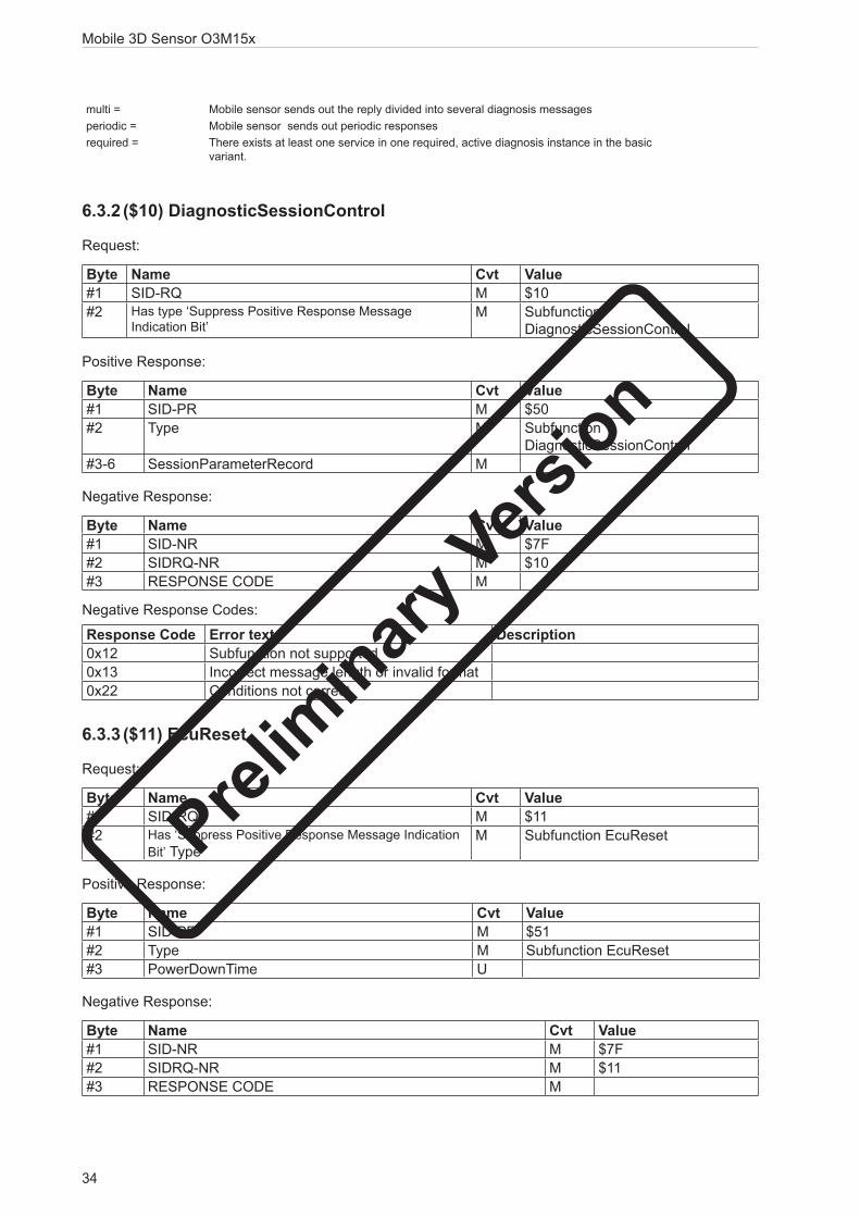
multi = Mobile sensor sends out the reply divided into several diagnosis messagesperiodic = Mobile sensor sends out periodic responsesrequired = There exists at least one service in one required, active diagnosis instance in the basic
variant .
6.3.2 ($10) DiagnosticSessionControl
Request:
Byte Name Cvt Value#1 SID-RQ M $10#2 Has type ‘Suppress Positive Response Message
Indication Bit’M Subfunction
DiagnosticSessionControl
Positive Response:
Byte Name Cvt Value#1 SID-PR M $50#2 Type M Subfunction
DiagnosticSessionControl#3-6 SessionParameterRecord M
Negative Response:
Byte Name Cvt Value#1 SID-NR M $7F#2 SIDRQ-NR M $10#3 RESPONSE CODE M
Negative Response Codes:
Response Code Error text Description0x12 Subfunction not supported0x13 Incorrect message length or invalid format0x22 Conditions not correct
6.3.3 ($11) EcuReset
Request:
Byte Name Cvt Value#1 SID-RQ M $11#2 Has ‘Suppress Positive Response Message Indication
Bit’ TypeM Subfunction EcuReset
Positive Response:
Byte Name Cvt Value#1 SID-PR M $51#2 Type M Subfunction EcuReset#3 PowerDownTime U
Negative Response:
Byte Name Cvt Value#1 SID-NR M $7F#2 SIDRQ-NR M $11#3 RESPONSE CODE M
Prelim
inary Vers
ion
35
Mobile 3D Sensor O3M15x
UK
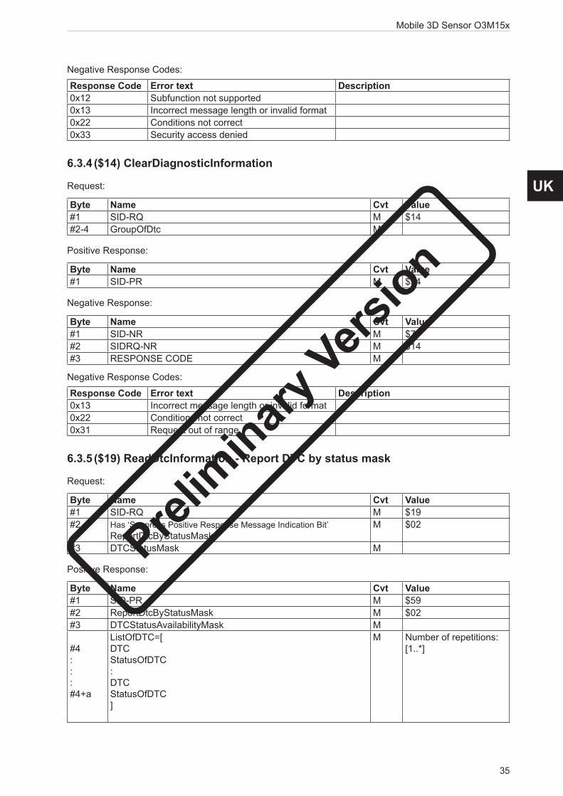
Negative Response Codes:
Response Code Error text Description0x12 Subfunction not supported0x13 Incorrect message length or invalid format0x22 Conditions not correct0x33 Security access denied
6.3.4 ($14) ClearDiagnosticInformation
Request:
Byte Name Cvt Value#1 SID-RQ M $14#2-4 GroupOfDtc M
Positive Response:
Byte Name Cvt Value#1 SID-PR M $54
Negative Response:
Byte Name Cvt Value#1 SID-NR M $7F#2 SIDRQ-NR M $14#3 RESPONSE CODE M
Negative Response Codes:
Response Code Error text Description0x13 Incorrect message length or invalid format0x22 Conditions not correct0x31 Request out of range
6.3.5 ($19) ReadDtcInformation - Report DTC by status mask
Request:
Byte Name Cvt Value#1 SID-RQ M $19#2 Has ‘Suppress Positive Response Message Indication Bit’
ReportDtcByStatusMaskM $02
#3 DTCStatusMask M
Positive Response:
Byte Name Cvt Value#1 SID-PR M $59#2 ReportDtcByStatusMask M $02#3 DTCStatusAvailabilityMask M #4 : : : #4+a
ListOfDTC=[ DTC StatusOfDTC : DTC StatusOfDTC ]
M Number of repetitions: [1 . .*]
Prelim
inary Vers
ion

Mobile 3D Sensor O3M15x
36
Negative Response:
Byte Name Cvt Value#1 SID-NR M $7F#2 SIDRQ-NR M $19#3 RESPONSE CODE M
Negative Response Codes:
Response Code Error text Description0x12 Subfunction not supported0x13 Incorrect message length or invalid format0x31 Request out of range
6.3.6 ($19) ReadDtcInformation - Report DTC extended data record by DTC number
Request:
Byte Name Cvt Value#1 SID-RQ M $19#2 Has ‘Suppress Positive Response Message Indication Bit’
ReportDTCExtendedDataRecordByDtcNumberM $06
#3-5 DTC M#6 AvailableExtendedDataRecordNumbers M
Positive Response:
Byte Name Cvt Value#1 SID-PR M $59#2 ReportDTCExtendedDataRecordByDtcNumber M $06#3-5 DTC M#6 Status Of Dtc M #7 : : : #7+a
EndOfServiceIteration=[ ExtendedDataRecordNumber ExtendedDataRecord : ExtendedDataRecordNumber ExtendedDataRecord ]
M Number of repetitions: [1 . .*]
Negative Response:
Byte Name Cvt Value#1 SID-NR M $7F#2 SID-RQ-NR M $19#3 RESPONSE CODE M
Negative Response Codes:
Response Code Error text Description0x12 Subfunction not supported0x13 Incorrect message length or invalid format0x31 Request out of range
Prelim
inary Vers
ion

37
Mobile 3D Sensor O3M15x
UK
6.3.7 ($19) ReadDtcInformation - Report number of DTC by status mask
Request:
Byte Name Cvt Value#1 SID-RQ M $19#2 Has ‘Suppress Positive Response Message Indication Bit’
ReportNumberOfDtcByStatusMaskM $01
#3 DTCStatusMask M
Positive Response:
Byte Name Cvt Value#1 SID-PR M $59#2 ReportNumberOfDtcByStatusMask M $01#3 DTCStatusAvailabilityMask M#4 DTCFormatIdentifier M#5-6 DTCCount M (fd)
Negative Response:
Byte Name Cvt Value#1 SID-NR M $7F#2 SIDRQ-NR M $19#3 RESPONSE CODE M
Negative Response Codes:
Response Code Error text Description0x12 Subfunction not supported0x13 Incorrect message length or invalid format0x31 Request out of range
6.3.8 ($19) ReadDtcInformation - Report supported DTC
Request:
Byte Name Cvt Value#1 SID-RQ M $19#2 Has ‘Suppress Positive Response Message Indication Bit’
ReportSupportedDTCM $0A
Positive Response:
Byte Name Cvt Value#1 SID-PR M $59#2 ReportSupportedDTC M $0A#3 DTCStatusAvailabilityMask M #4 : : : #4+a
ListOfDTCAndStatus=[ DTC statusOfDTC : DTC statusOfDTC ]
M Number of repetitions: [1 . .*]
Prelim
inary Vers
ion

Mobile 3D Sensor O3M15x
38
Negative Response:
Byte Name Cvt Value#1 SID-NR M $7F#2 SID-RQ-NR M $19#3 RESPONSE CODE M
Negative Response Codes:
Response Code Error text Description0x12 Subfunction not supported0x13 Incorrect message length or invalid format0x31 Request out of range
6.3.9 ($19) ReadDtcInformation - ReportDTCFaultDetectionCounter
Request:
Byte Name Cvt Value#1 SID-RQ M $19#2 Has ‘Suppress Positive Response Message Indication Bit’
reportDTCFaultDetectionCounterM $14
Positive Response:
Byte Name Cvt Value#1 SID-PR M $59#2 reportDTCFaultDetectionCounter M $14 #3 : : : #3+a
DTCFaultDetectionCounterRecord=[ DTC DTCFaultDetectionCounter : DTC DTCFaultDetectionCounter ]
M Number of repetitions: [1 . .*]
Negative Response:
Byte Name Cvt Value#1 SID-NR M $7F#2 SID-RQ-NR M $19#3 RESPONSE CODE M
6.3.10 ($19)ReadDtcInformation-ReportDtcSnapshotIdentification
Request:
Byte Name Cvt Value#1 SID-RQ M $19#2 Has ‘Suppress Positive Response Message Indication Bit’
ReportDtcSnapshotIdentificationM $03
Positive Response:
Byte Name Cvt Value#1 SID-PR M $59#2 ReportDtcSnapshotIdentification M $03
Prelim
inary Vers
ion

39
Mobile 3D Sensor O3M15x
UK
Byte Name Cvt Value #3 : : : #3+a
DTCAndDTCSnapshotRecordNumber=[ DTC DTCSnapshotRecordNumber : DTC DTCSnapshotRecordNumber ]
M Number of repetitions: [1 . .*]
Negative Response:
Byte Name Cvt Value#1 SID-NR M $7F#2 SID-RQ-NR M $19#3 RESPONSE CODE M
Negative Response Codes:
Response Code Error text Description0x12 Subfunction not supported0x13 Incorrect message length or invalid format0x31 Request out of range
6.3.11 ($19)ReadDtcInformation-ReportFirstConfirmedDTC
Request:
Byte Name Cvt Value#1 SID-RQ M $19#2 Has ‘Suppress Positive Response Message Indication Bit’
ReportFirstConfirmedDTCM $0C
Positive Response:
Byte Name Cvt Value#1 SID-PR M $59#2 ReportFirstConfirmedDTC M $0C#3 DTCStatusAvailabilityMask M #4 : : : #4+a
ListOfDTC=[ DTC statusOfDTC : DTC statusOfDTC ]
M Number of repetitions: [0 . .1]
Negative Response:
Byte Name Cvt Value#1 SID-NR M $7F#2 SID-RQ-NR M $19#3 RESPONSE CODE M
Negative Response Codes:
Response Code Error text Description0x12 Subfunction not supported0x13 Incorrect message length or invalid format0x31 Request out of range
Prelim
inary Vers
ion

Mobile 3D Sensor O3M15x
40
6.3.12 ($19) ReadDtcInformation - ReportFirstTestFailedDTC
Request:
Byte Name Cvt Value#1 SID-RQ M $19#2 Has ‘Suppress Positive Response Message Indication Bit’
SubfunctionM $0B
Positive Response:
Byte Name Cvt Value#1 SID-PR M $59#2 Subfunction M $0B#3 StatusAvailabilityMask M #4 : : : #4+a
ListOfDTC=[ DTC StatusOfDTC : DTC StatusOfDTC ]
M Number of repetitions: [0 . .1]
Negative Response:
Byte Name Cvt Value#1 SID-NR M $7F#2 SID-RQ-NR M $19#3 RESPONSE CODE M
Negative Response Codes:
Response Code Error text Description0x12 Subfunction not supported0x13 Incorrect message length or invalid format0x31 Request out of range
6.3.13 ($19)ReadDtcInformation-ReportMostRecentConfirmedDTC
Request:
Byte Name Cvt Value#1 SID-RQ M $19#2 Has ‘Suppress Positive Response Message Indication Bit’
ReportMostRecentConfirmedDTCM $0E
Positive Response:
Byte Name Cvt Value#1 SID-PR M $59#2 ReportMostRecentConfirmedDTC M $0E#3 DTCStatusAvailabilityMask M
Prelim
inary Vers
ion

41
Mobile 3D Sensor O3M15x
UK
Byte Name Cvt Value #4 : : : #4+a
ListOfDTC=[ DTC statusOfDTC : DTC statusOfDTC ]
M Number of repetitions: [0 . .1]
Negative Response:
Byte Name Cvt Value#1 SID-NR M $7F#2 SID-RQ-NR M $19#3 RESPONSE CODE M
Negative Response Codes:
Response Code Error text Description0x12 Subfunction not supported0x13 Incorrect message length or invalid format0x31 Request out of range
6.3.14 ($19) ReadDtcInformation - ReportMostRecentTestFailedDTC
Request:
Byte Name Cvt Value#1 SID-RQ M $19#2 Has ‘Suppress Positive Response Message Indication Bit’
SubfunctionM $0D
Positive Response:
Byte Name Cvt Value#1 SID-PR M $59#2 Subfunction M $0D#3 DTCAvailabilityMask M #4 : : : #4+a
ListOfDTCAndStatusRecord=[ DTC StatusOfDTC : DTC StatusOfDTC ]
M Number of repetitions: [0 . .1]
Negative Response:
Byte Name Cvt Value#1 SID-NR M $7F#2 SID-RQ-NR M $19#3 RESPONSE CODE M
Negative Response Codes:
Response Code Error text Description0x12 Subfunction not supported0x13 Incorrect message length or invalid format0x31 Request out of range
Prelim
inary Vers
ion

Mobile 3D Sensor O3M15x
42
6.3.15 ($22)ReadDataByIdentifierWithin one request it is possible to combine several different identifier, in the response these identifiers will be sent with the according data . (*)
Request:
Byte Name Cvt Value#1 SID-RQ M $22#2-3 Identifier (Byteorder: HighLow (Motorola))(*) M DataIdentifier
Positive Response:
Byte Name Cvt Value#1 SID-PR M $62#2-3 Identifier (Byteorder: HighLow (Motorola))(*) M DataIdentifier#4-4+a DataRecord M
Negative Response:
Byte Name Cvt Value#1 SID-NR M $7F#2 SIDRQ-NR M $22#3 RESPONSE CODE M
Negative Response Codes:
Response Code Error text Description0x13 Incorrect message length or invalid format0x22 Conditions not correct0x31 Request out of range0x33 Security access denied
6.3.16 ($23) ReadMemoryByAddress
Request:
Byte Name Cvt Value#1 SID-RQ M $23#2 Address and Length Format Identifier M (fd)#3-3+a Address and Size M (fd)
Positive Response:
Byte Name Cvt Value#1 SID-PR M $63#2-2+a DataRecord M
Negative Response:
Byte Name Cvt Value#1 SID-NR M $7F#2 SIDRQ-NR M $23#3 RESPONSE CODE M
Negative Response Codes:
Response Code Error text Description0x13 Incorrect message length or invalid format0x22 Conditions not correct0x31 Request out of range0x33 Security access denied
Prelim
inary Vers
ion

43
Mobile 3D Sensor O3M15x
UK
6.3.17 ($27) SecurityAccess - Request seed
Request:
Byte Name Cvt Value#1 SID-RQ M $27#2 Has ‘Suppress Positive Response Message Indication Bit’
TypeM Subfunction
SecurityAccess
Positive Response:
Byte Name Cvt Value#1 SID-PR M $67#2 Type M Subfunction
SecurityAccess#3-3+a SecuritySeed M
Negative Response:
Byte Name Cvt Value#1 SID-NR M $7F#2 SIDRQ-NR M $27#3 RESPONSE CODE M
Negative Response Codes:
Response Code Error text Description0x12 Subfunction not supported0x13 Incorrect message length or invalid format0x22 Conditions not correct0x24 Request sequence error0x31 Request out of range0x35 Invalid key0x36 Exceed number of attempts0x37 Required time delay not expired
6.3.18 ($27) SecurityAccess - Send key
Request:
Byte Name Cvt Value#1 SID-RQ M $27#2 Has ‘Suppress Positive Response Message Indication Bit’
TypeM Subfunction
SecurityAccess#3-3+a SecurityKey M
Positive Response:
Byte Name Cvt Value#1 SID-PR M $67#2 Type M Subfunction
SecurityAccess
Negative Response:
Byte Name Cvt Value#1 SID-NR M $7F#2 SIDRQ-NR M $27#3 RESPONSE CODE M
Prelim
inary Vers
ion

Mobile 3D Sensor O3M15x
44
Negative Response Codes:
Response Code Error text Description0x12 Subfunction not supported0x13 Incorrect message length or invalid format0x22 Conditions not correct0x24 Request sequence error0x31 Request out of range0x35 Invalid key0x36 Exceed number of attempts0x37 Required time delay not expired
6.3.19 ($28) CommunicationControl
Request:
Byte Name Cvt Value#1 SID-RQ M $28#2 Has ‘Suppress Positive Response Message Indication Bit’
TypeM Subfunction
CommunicationControl#3 CommunicationType M
Positive Response:
Byte Name Cvt Value#1 SID-PR M $68#2 Type M Subfunction
CommunicationControl
Negative Response:
Byte Name Cvt Value#1 SID-NR M $7F#2 SIDRQ-NR M $28#3 RESPONSE CODE M
Negative Response Codes:
Response Code Error text Description0x12 Subfunction not supported0x13 Incorrect message length or invalid format0x22 Conditions not correct0x31 Request out of range0x33 Security access denied
6.3.20 ($2E)WriteDataByIdentifier
Request:
Byte Name Cvt Value#1 SID-RQ M $2E#2-3 Identifier (Byteorder: HighLow (Motorola)) M DataIdentifier#4-4+a DataRecord M
Positive Response:
Byte Name Cvt Value#1 SID-PR M $6E#2-3 Identifier (Byteorder: HighLow (Motorola)) M DataIdentifier
Prelim
inary Vers
ion

45
Mobile 3D Sensor O3M15x
UK
Negative Response:
Byte Name Cvt Value#1 SID-NR M $7F#2 SIDRQ-NR M $2E#3 RESPONSE CODE M
Negative Response Codes:
Response Code Error text Description0x13 Incorrect message length or invalid format0x22 Conditions not correct0x31 Request out of range0x33 Security access denied0x72 General programming failure
6.3.21 ($31) RoutineControl - Start routine
Request:
Byte Name Cvt Value#1 SID-RQ M $31#2 Has ‘Suppress Positive Response Message Indication Bit’
RoutineControlTypeM $01
#3-4 Identifier (Byteorder: HighLow (Motorola)) M RoutineIdentifier#5-5+a RoutineControlOptionRecord -
Positive Response:
Byte Name Cvt Value#1 SID-PR M $71#2 RoutineControlType M $01#3-4 Identifier (Byteorder: HighLow (Motorola)) M RoutineIdentifier#5-5+a RoutineStatusRecord -
Negative Response:
Byte Name Cvt Value#1 SID-NR M $7F#2 SIDRQ-NR M $31#3 RESPONSE CODE M
Negative Response Codes:
Response Code Error text Description0x12 Subfunction not supported0x13 Incorrect message length or invalid format0x22 Conditions not correct0x24 Request sequence error0x31 Request out of range0x33 Security access denied0x72 General programming failure
6.3.22 ($34) RequestDownload
Request:
Byte Name Cvt Value#1 SID-RQ M $34#2 DataFormatIdentifier M
Prelim
inary Vers
ion
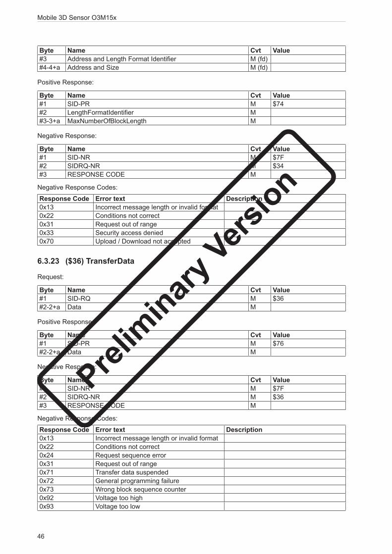
Mobile 3D Sensor O3M15x
46
Byte Name Cvt Value#3 Address and Length Format Identifier M (fd)#4-4+a Address and Size M (fd)
Positive Response:
Byte Name Cvt Value#1 SID-PR M $74#2 LengthFormatIdentifier M#3-3+a MaxNumberOfBlockLength M
Negative Response:
Byte Name Cvt Value#1 SID-NR M $7F#2 SIDRQ-NR M $34#3 RESPONSE CODE M
Negative Response Codes:
Response Code Error text Description0x13 Incorrect message length or invalid format0x22 Conditions not correct0x31 Request out of range0x33 Security access denied0x70 Upload / Download not accepted
6.3.23 ($36) TransferData
Request:
Byte Name Cvt Value#1 SID-RQ M $36#2-2+a Data M
Positive Response:
Byte Name Cvt Value#1 SID-PR M $76#2-2+a Data M
Negative Response:
Byte Name Cvt Value#1 SID-NR M $7F#2 SIDRQ-NR M $36#3 RESPONSE CODE M
Negative Response Codes:
Response Code Error text Description0x13 Incorrect message length or invalid format0x22 Conditions not correct0x24 Request sequence error0x31 Request out of range0x71 Transfer data suspended0x72 General programming failure0x73 Wrong block sequence counter0x92 Voltage too high0x93 Voltage too low
Prelim
inary Vers
ion
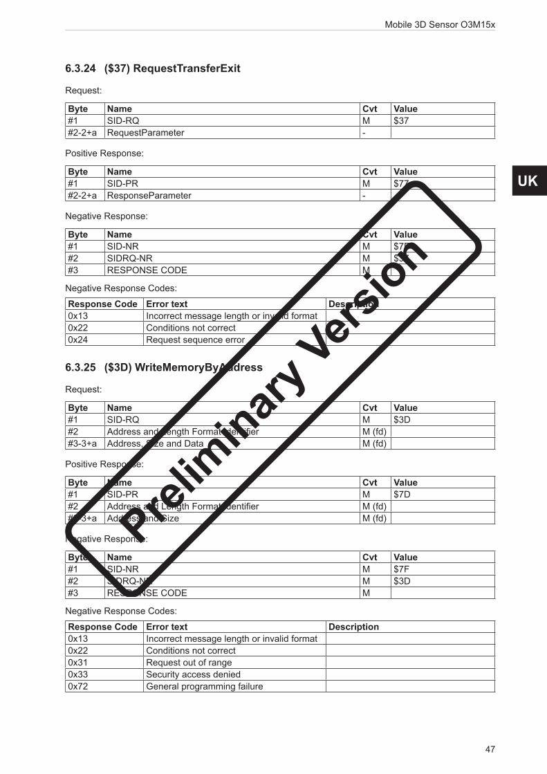
47
Mobile 3D Sensor O3M15x
UK
6.3.24 ($37) RequestTransferExit
Request:
Byte Name Cvt Value#1 SID-RQ M $37#2-2+a RequestParameter -
Positive Response:
Byte Name Cvt Value#1 SID-PR M $77#2-2+a ResponseParameter -
Negative Response:
Byte Name Cvt Value#1 SID-NR M $7F#2 SIDRQ-NR M $37#3 RESPONSE CODE M
Negative Response Codes:
Response Code Error text Description0x13 Incorrect message length or invalid format0x22 Conditions not correct0x24 Request sequence error
6.3.25 ($3D) WriteMemoryByAddress
Request:
Byte Name Cvt Value#1 SID-RQ M $3D#2 Address and Length Format Identifier M (fd)#3-3+a Address, Size and Data M (fd)
Positive Response:
Byte Name Cvt Value#1 SID-PR M $7D#2 Address and Length Format Identifier M (fd)#3-3+a Address and Size M (fd)
Negative Response:
Byte Name Cvt Value#1 SID-NR M $7F#2 SIDRQ-NR M $3D#3 RESPONSE CODE M
Negative Response Codes:
Response Code Error text Description0x13 Incorrect message length or invalid format0x22 Conditions not correct0x31 Request out of range0x33 Security access denied0x72 General programming failure
Prelim
inary Vers
ion
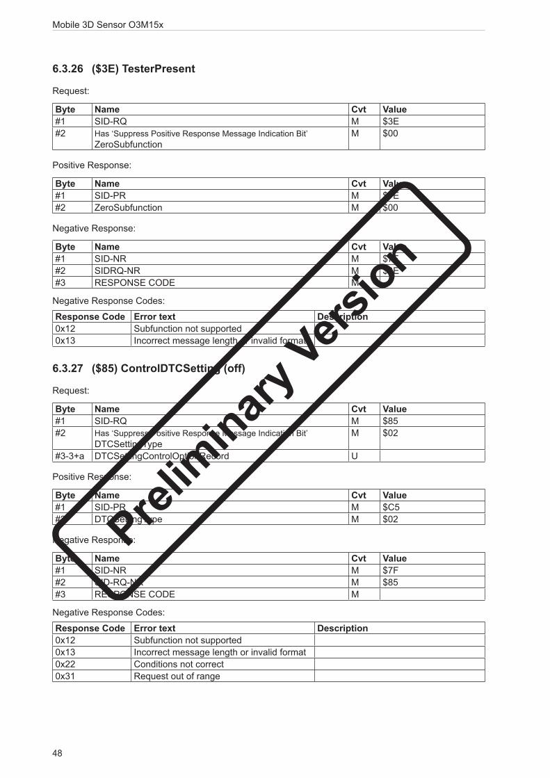
Mobile 3D Sensor O3M15x
48
6.3.26 ($3E) TesterPresent
Request:
Byte Name Cvt Value#1 SID-RQ M $3E#2 Has ‘Suppress Positive Response Message Indication Bit’
ZeroSubfunctionM $00
Positive Response:
Byte Name Cvt Value#1 SID-PR M $7E#2 ZeroSubfunction M $00
Negative Response:
Byte Name Cvt Value#1 SID-NR M $7F#2 SIDRQ-NR M $3E#3 RESPONSE CODE M
Negative Response Codes:
Response Code Error text Description0x12 Subfunction not supported0x13 Incorrect message length or invalid format
6.3.27 ($85) ControlDTCSetting (off)
Request:
Byte Name Cvt Value#1 SID-RQ M $85#2 Has ‘Suppress Positive Response Message Indication Bit’
DTCSettingType M $02
#3-3+a DTCSettingControlOptionRecord U
Positive Response:
Byte Name Cvt Value#1 SID-PR M $C5#2 DTCSettingType M $02
Negative Response:
Byte Name Cvt Value#1 SID-NR M $7F#2 SID-RQ-NR M $85#3 RESPONSE CODE M
Negative Response Codes:
Response Code Error text Description0x12 Subfunction not supported0x13 Incorrect message length or invalid format0x22 Conditions not correct0x31 Request out of range
Prelim
inary Vers
ion

49
Mobile 3D Sensor O3M15x
UK
6.3.28 ($85) ControlDTCSetting (on)
Request:
Byte Name Cvt Value#1 SID-RQ M $85#2 Has ‘Suppress Positive Response Message Indication Bit’
DTCSettingTypeM $01
#3-3+a DTCSettingControlOptionRecord U
Positive Response:
Byte Name Cvt Value#1 SID-PR M $C5#2 DTCSettingType M $01
Negative Response:
Byte Name Cvt Value#1 SID-NR M $7F#2 SID-RQ-NR M $85#3 RESPONSE CODE M
Negative Response Codes:
Response Code Error text Description0x12 Subfunction not supported0x13 Incorrect message length or invalid format0x22 Conditions not correct0x31 Request out of range
6.3.29 Negative ResponsesIn case the Mobile sensor could not respond to a request, then the mobile sensor will reply with the following Negative Response Codes (depending on the error) . Specific Negative Response Codes are described at the according Service.
Table 8: Supported negative Response Codes
Response Code Error text Description0x10 General reject0x11 Service not supported0x12 Subfunction not supported0x13 Incorrect message length or invalid format0x14 Response too long0x21 Busy repeat request0x22 Conditions not correct0x24 Request sequence error0x31 Request out of range0x33 Security access denied0x35 Invalid key0x36 Exceed number of attempts0x37 Required time delay not expired0x70 Upload / Download not accepted0x71 Transfer data suspended0x72 General programming failure0x73 Wrong block sequence counter
Prelim
inary Vers
ion

Mobile 3D Sensor O3M15x
50
Response Code Error text Description0x78 Request correctly received - response
pending0x7E Subfunction not supported in active session0x7F Service not supported in active session0x81 RPM too high0x82 RPM too low0x83 Engine is running0x84 Engine is not running0x85 Engine runtime too low0x86 Temperature too high0x87 Temperature too low0x88 Vehicle speed too high0x89 Vehicle speed too low0x8A Throttle / Pedal too high0x8B Throttle / Pedal too low0x8C Transmission range not in neutral0x8D Transmission range not in gear0x8F Break switch(es) not closed0x90 Shifter lever not in park0x91 Torque converter clutch locked0x92 Voltage too high0x93 Voltage too low
Table 9: Negative Response Codes for unsupported services
Response Code Error text Description0x11 Service not supported0x12 Subfunction not supported0x31 Request out of range
6.4 Ethernet interfaceThe Ethernet is used only for output data .The mobile sensor is sending out data via IP and UDP protocols .The mobile sensor supports addresses of type IP v4, fixed addresses or broadcast.For the default configuration of the Ethernet output refer to chapter (Fehler! Verweisquelle konnte nicht gefunden werden. Fehler! Verweisquelle konnte nicht gefunden werden.), parameters
- Ipv4AddressSensor,- SubnetMask, - Ipv4AddressDestination, - destinationUDPPort
Prelim
inary Vers
ion

51
Mobile 3D Sensor O3M15x
UK
6.4.1 iMeas format
6.4.2 OverviewThe Ethernet output of the O3M is organized as follows:
1 . O3M sensor1 .1 . KP Device
1 .1 .1 . Measurement Cycle (according to cycle time)1 .1 .1 .1 . KP Customer Output Channel1 .1 .1 .2 . KP Debug Channel 11 .1 .1 .3 . KP Debug Channel 21 .1 .1 .4 . …
1 .2 . DSP Device1 .2 .1 . Measurement Cycle (according to cycle time)
1 .2 .1 .1 . DSP Customer Output Channel1 .2 .1 .2 . DSP Debug Channel 11 .2 .1 .3 . DSP Debug Channel 21 .2 .1 .4 . …
Each channel is a binary large object (BLOB) and the description of the data format is provided in separate documents .
The O3M sensor uses the UDP protocol for the Ethernet output . Therefore, the channel data has to be split up into UDP packets . The protocol used is described in this document .
6.4.3 O3M Output Protocol
6.4.4 Channel Format
At the start of each channel there is a start delimiter and a channel header and at the end of the channel there is an end delimiter . The channel contains reserved information used by ifm .
Offset 0 1 2 3 4 5 6 7 8 9 10 11 12 13 14 15 16 17 18 19 20 21 22 23 24 25 26 27 ..Description
Length 4 Byte
End Delimiter
Binary Payload…
n byte
reserved
24 byte4 byte
StartDelimiter
• Start Delimiter: 0xaa55aa55
• End Delimiter: 0x55aa55aa
6.4.5 UDP PacketsThe above defined channels are split up into several UDP packets. Each UDP packet has the format described below:
Offset 0 1 2 3 4 5 6 7 8 9 10 11 12 13 14 15Description Version
Length 2 Byte
Reserved
2 Byte
Index of packet in
cycle
Packet Counter
4 byte
Cycle Counter
4 byte
Number of packets in
cycle
2 byte2 byte
Prelim
inary Vers
ion

Mobile 3D Sensor O3M15x
52
16 17 18 19 20 21 22 23 24 25 26 27 28 29 30 31 32 … … …
2 byte
Length Payload (incl. channel
header)
4 byte
Total length of channel (in byte)
in this cycle
4 byte
Number of
packets in
channel
2 byte
Index of packet in channel
4 byte
Channel part as referenced by
"Index of packet in channel"
Channel ID
Byte order: Little Endian
• Version Length: 2 byte Value: 3 Protocol version used .
• Reserved Length: 2 byte
• Packet Counter Length: 4 byte Counts up with each UDP packet . Should be used to check for missing packets . Set to zero at reset . Wraparound at overrun .
• Cycle counter Length: 4 byte Counter for the measurement cycles . Set to zero at reset .
• Number of UDP packets in this cycle Length: 2 byte Total number of UDP packets for the current cycle (all channels) .
• Index of the UDP packet in this cycle Length: 2 byte Example: If a cycle consists of 20 packets, the index goes from 0 to 19
• Number of UDP packets in this channel Length: 2 byte
• Index of UDP packet in this channel Length: 2 byte
• Channel ID Length: 4 byte Can be used to filter for data of interest. Channel 8 is the customer output channel containing the O3M measurement output .
• Total Length of channel (in bytes) in this cycle Length: 4 byte
• Payload/actual data Length: n bytes For the structure definition of the payload, see separate XML documents.
Prelim
inary Vers
ion