Operating instructions Airlock MPSN-66543-1-1-1308-en-US ...-ex)airlock... · Operating...
38
Operating instructions Airlock MPSN-MS (-Ex) Original operating instructions MPSN-66543-1-1-1308-en-US
Transcript of Operating instructions Airlock MPSN-66543-1-1-1308-en-US ...-ex)airlock... · Operating...

Operating instructions Airlock MPSN-MS (-Ex)
Original operating instructionsMPSN-66543-1-1-1308-en-US

Table of contents
1 Important information 51.1 Scope of validity ............................................................................................ 51.2 Applicable documents ................................................................................... 51.3 Contact .......................................................................................................... 5
1.3.1 Address .......................................................................................... 51.3.2 Feedback regarding this manual .................................................. 5
1.4 Personnel qualifications ................................................................................ 51.4.1 Mechanics ...................................................................................... 51.4.2 Electrician ...................................................................................... 61.4.3 Welders .......................................................................................... 6
1.5 Presentation conventions .............................................................................. 61.5.1 Explanation of warnings ................................................................ 6
2 Safety 72.1 Intended use ................................................................................................. 72.2 Technical condition ....................................................................................... 72.3 ATEX labeling ............................................................................................... 72.4 Personnel qualifications ................................................................................ 72.5 Safety devices ............................................................................................... 82.6 Safety markings ............................................................................................ 82.7 Safe working environment ............................................................................ 8
2.7.1 Slipping and tripping hazards ....................................................... 8
3 Technical data 93.1 Ambient conditions ........................................................................................ 93.2 Performance characteristics .......................................................................... 9
3.2.1 Maximum permissible torque ........................................................ 93.2.2 Rotor volume ................................................................................. 9
3.3 Operating temperature .................................................................................. 103.4 Airborne noise emission ............................................................................... 10
3.4.1 Measured values ........................................................................... 103.5 Weights and volumes ................................................................................... 10
3.5.1 Transport weights not including drive .......................................... 103.5.2 Transport weights including drive ................................................. 103.5.3 Volumes packaged in seaworthy manner .................................... 10
3.6 Dimensions .................................................................................................... 113.7 Pneumatic system ......................................................................................... 123.8 Options .......................................................................................................... 12
4 Description 134.1 Identification .................................................................................................. 13
4.1.1 Type plate ...................................................................................... 134.1.2 Type code ...................................................................................... 134.1.3 ATEX designation for use in Ex zone 22 .................................... 144.1.4 ATEX designation without approval for use in potentially explo-
sive zones ..................................................................................... 14
2Bühler AGMPSN-66543-1-1-1308-en-USTable of contents

4.2 Overview ........................................................................................................ 144.3 Mode of operation ......................................................................................... 154.4 EMERGENCY STOP .................................................................................... 164.5 Protection devices ......................................................................................... 164.6 Safety symbols .............................................................................................. 16
5 Transport 185.1 Packaging symbols ....................................................................................... 185.2 Checking delivery .......................................................................................... 185.3 Temporary storage ........................................................................................ 185.4 Lifting instructions ......................................................................................... 19
6 Installation 206.1 Preparing installation location ....................................................................... 206.2 Series arrangement ....................................................................................... 216.3 Connecting the utilities .................................................................................. 21
6.3.1 Electrical systems .......................................................................... 21
7 Commissioning 237.1 Checking commissioning .............................................................................. 23
7.1.1 Checking the rotor ......................................................................... 237.2 Conformity ..................................................................................................... 24
7.2.1 Checking EC conformity ............................................................... 24
8 Operation 258.1 Starting and stopping .................................................................................... 25
8.1.1 Starting .......................................................................................... 258.1.2 Stopping ......................................................................................... 25
8.2 Checks during operation ............................................................................... 25
9 Trouble-shooting 269.1 Faults ............................................................................................................. 26
10 Maintenance 2710.1 Cleaning ........................................................................................................ 2710.2 Lubrication ..................................................................................................... 27
10.2.1 Lubrication schedule ..................................................................... 2710.2.2 Bearing .......................................................................................... 27
10.3 Maintenance .................................................................................................. 2810.3.1 Maintenance schedule .................................................................. 2810.3.2 Maintaining airlock ......................................................................... 28
11 Maintenance and repair 3011.1 Replace speed sensor .................................................................................. 30
11.1.1 Removing speed sensor ............................................................... 3011.1.2 Installing speed sensor ................................................................. 32
11.2 Replacing bearing and shaft seal ................................................................ 3411.2.1 Removing bearing and shaft seal ................................................ 3411.2.2 Fitting bearing and shaft seal ....................................................... 34
11.3 Replacing rotor .............................................................................................. 34
12 Decommissioning 3612.1 Dismantle ....................................................................................................... 3612.2 Disposal ......................................................................................................... 36
Bühler AGMPSN-66543-1-1-1308-en-US
Table of contents 3

12.2.1 Disposal of operating materials .................................................... 3612.2.2 Disposing of machine .................................................................... 36
4Bühler AGMPSN-66543-1-1-1308-en-USTable of contents
1 Important information
1.1 Scope of validity
TypeMPSN-25/15-MS MPSN-25/15-MS-Ex
MPSN-25/23-MS MPSN-25/23-MS-Ex
MPSN-28/30-MS MPSN-28/30-MS-Ex
1.2 Applicable documents
Designation Identification numberGearmotor Refer to the manufacturer's documentation.
Frequency converter Refer to the manufacturer's documentation.
Speed monitoring Refer to the manufacturer's documentation.
Spare parts catalog MPSN-8230-x-1
1.3 Contact
► If you have any questions, please contact the relevant branch of the manu-facturer.
► Keep the instructions to hand.
1.3.1 Address
Bühler AGCustomer Service Grain ProcessingCH-9240 Uzwil, Schweiz+41 71 955 30 40+41 71 955 33 [email protected]
1.3.2 Feedback regarding this manual
Requests and suggestions relevant to this [email protected].
1.4 Personnel qualifications
1.4.1 Mechanics
Individuals who work on mechanical equipment must be technically trained orhave attended and passed the manufacturer's training.
Bühler AGMPSN-66543-1-1-1308-en-US
Chapter 1 Important information 5
1.4.2 Electrician
Individuals who work on electrical equipment must be technically trained or haveattended and passed the manufacturer's training.
1.4.3 Welders
Personnel who weld on the equipment must have specialized training.
1.5 Presentation conventions
1.5.1 Explanation of warnings
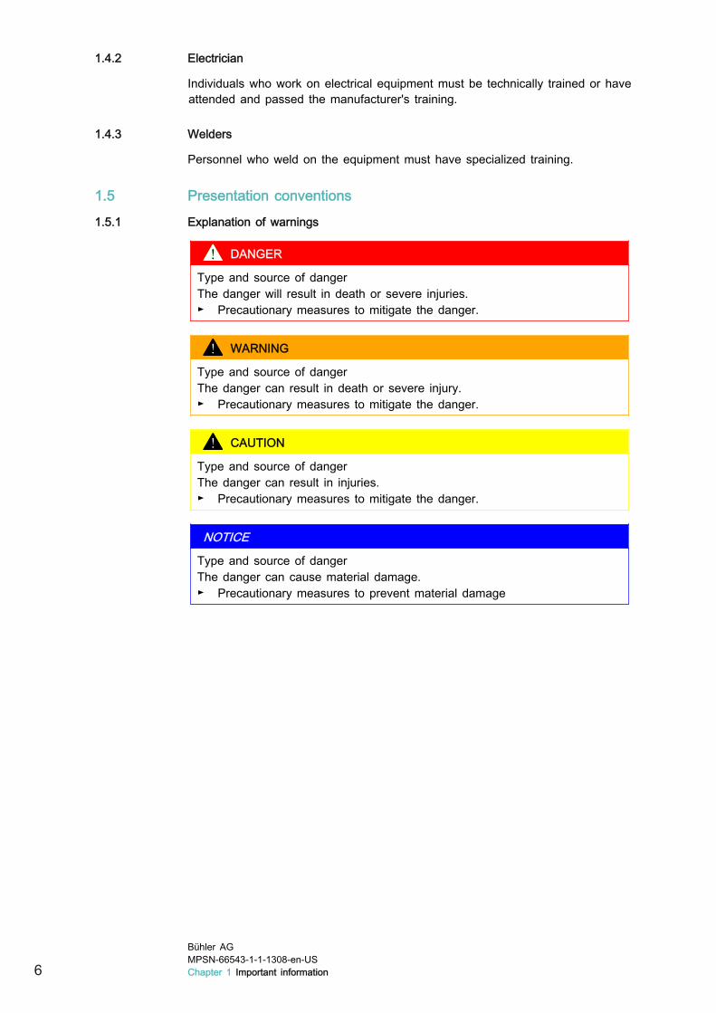
DANGER
Type and source of dangerThe danger will result in death or severe injuries.► Precautionary measures to mitigate the danger.
WARNING
Type and source of dangerThe danger can result in death or severe injury.► Precautionary measures to mitigate the danger.
CAUTION
Type and source of dangerThe danger can result in injuries.► Precautionary measures to mitigate the danger.
NOTICE
Type and source of dangerThe danger can cause material damage.► Precautionary measures to prevent material damage
6Bühler AGMPSN-66543-1-1-1308-en-USChapter 1 Important information

2 Safety
2.1 Intended use
The airlock is designed for powdery to granular, free-flowing bulk materials inaccordance with the requirements list. It is used to feed pneumatic intake andpressurized conveyance lines, for volumetric metering and for discharge from fil-ters and other containers.
► Use the machine only as intended.► Only operate the machine in accordance with the instructions in these oper-
ating instructions.
2.2 Technical condition
If the machine is in poor technical condition, safety, proper operation and availa-bility are compromised.
► Operate the machine only when it is in faultless technical condition.► Comply with the maintenance schedule.► Use only genuine replacement parts as listed in the spare parts catalog.► If the performance characteristics of the machine change, check the machine
for malfunctions.► Correct malfunctions immediately.► The machine must not be modified or altered without approval from the man-
ufacturer.
2.3 ATEX labeling
The ATEX designation indicates the conditions under which the machine may beused in a potentially explosive zone or connected to a potentially explosivezone.
► Note the type plate.
2.4 Personnel qualifications
Unqualified personnel cannot recognize risks and are thus exposed to greaterdanger.
► Allow only technically qualified personnel to perform the activities describedin these operating instructions.
► Ensure that personnel comply with local laws and regulations for safe andhazard-conscious work.
► Define and communicate work responsibilities. Only give keys and pass-words to appointed staff.
Bühler AGMPSN-66543-1-1-1308-en-US
Chapter 2 Safety 7

2.5 Safety devices
If safety devices are not functioning effectively, people are at risk.
► Before operating the machine, ensure that all safety devices are functioningeffectively.
2.6 Safety markings
If safety markings are not noticeable, people are at risk.
► Replace unreadable safety markings.► Do not remove or cover safety markings.
2.7 Safe working environment
2.7.1 Slipping and tripping hazards
Slippery surfaces and tripping hazards may result in serious accidents.
► Keep aisles, handles, steps, ladders, platforms and handrails free of grease,oil and other types of dirt.
► Do not use the machine as a climbing aid or storage area. Use only thesteps and platforms provided.
► Wear anti-slip safety shoes.
8Bühler AGMPSN-66543-1-1-1308-en-USChapter 2 Safety

3 Technical data
3.1 Ambient conditions
Description Value UnitTemperature range 0 … +40 °C
Relative humidity < 90 %
3.2 Performance characteristics
3.2.1 Maximum permissible torque
Description Value UnitMPSN-25/15 415 Nm
MPSN-25/23 415 Nm
MPSN-28/30 425 Nm
3.2.2 Rotor volume
Fig. 3.1
Description Value UnitMPSN-25/15 5.8 dm3
MPSN-25/23 9.0 dm3
MPSN-28/30 14.6 dm3
Bühler AGMPSN-66543-1-1-1308-en-US
Chapter 3 Technical data 9

3.3 Operating temperature
Description Value UnitFor low-temperature bulk material Up to 60 °C
ΔTmax (between ambient temperature and bulkmaterial temperature)
20 °C
3.4 Airborne noise emission
3.4.1 Measured values
The measured values do not take room effects into account.
Description Value UnitEquivalent workplace emission level Lp ≤ 70 dB (A)
3.5 Weights and volumes
3.5.1 Transport weights not including drive
Description Value UnitMPSN-25/15 50 kg
MPSN-25/23 65 kg
MPSN-28/30 85 kg
3.5.2 Transport weights including drive
Description Value UnitMPSN-25/15 85 kg
MPSN-25/23 100 kg
MPSN-28/30 115 kg
3.5.3 Volumes packaged in seaworthy manner
Description Value UnitMPSN-25/15 0.14 m3
MPSN-25/23 0.16 m3
MPSN-28/30 0.20 m3
10Bühler AGMPSN-66543-1-1-1308-en-USChapter 3 Technical data

3.6 Dimensions
B A
I
M N O
J K
P
L
H D
D E
ø 3
5h6
F
max. Q
max. Q
C
Fig. 3.2
MPSN 25/15 25/23 28/30A 320 * 410 * 490
B 160 205 320
C 320 320 350
D 160 160 175
E 10 10 12
F 57 57 137
H 220 330 370
I 120 200 270
J 100 150 200
K 175 270 335
L 240 240 320
M 150 150 220
N 100 150 200
O 205 210 285
P 8×M10 8×D 11.5 8×D 13.5
Q max. 520 560 640
* Standard shaft, other shafts are optional.
Bühler AGMPSN-66543-1-1-1308-en-US
Chapter 3 Technical data 11

3.7 Pneumatic system
Description Value UnitMaximum pressure in continuous operation 0.6 bar
Maximum upper pressure limit 0.8 bar
3.8 Options■ NORD or SEW gearmotor■ NORD or SEW spur gearmotor■ NORD or SEW bevel gearmotor■ Frequency converter MOVIMOT®■ Frequency converter TRIO SK200E■ Speed monitoring■ Airlock table
□ with intermediate shafts, couplings and covers■ Sight glass■ Transition piece for airlock outlet■ Feed nozzle■ Distribution box
12Bühler AGMPSN-66543-1-1-1308-en-USChapter 3 Technical data

4 Description
4.1 Identification
4.1.1 Type plate
Model:Serial No.: Manufactured:
* (2)(3)(4)
(5)
(1)
(6)
Fig. 4.1 Type plate
(1) Manufacturer (4) Year of manufacture(2) Place of manufacture (5) Machine number(3) Machine type (6) ATEX labeling
Position
Fig. 4.2 Airlock with drive
4.1.2 Type code
MPSN-25/23-MS-ExMPSN Machine code
25, 28 Rotor diameter in cm
15, 23, 30 Rotor length in cm
MS Mild steel version
Ex Approval for potentially explosive zone
Bühler AGMPSN-66543-1-1-1308-en-US
Chapter 4 Description 13

4.1.3 ATEX designation for use in Ex zone 22
The ATEX designation indicates the conditions under which the machine may beused in a potentially explosive zone or connected to a potentially explosivezone.
II */3D T=135 °C
Explanation of symbols:
→ ATEX symbol
II → Device group
*/ → Internal category: Does not have its own internal source of ignition
/3 → External category 3
D → Dust atmosphere
T → Maximum expected surface temperature in °C in normal operation atfull load and at an ambient temperature of 40 °C
4.1.4 ATEX designation without approval for use in potentially explosive zones
II */-D
Explanation of symbols:
→ ATEX symbol
II → Device group
*/ → Internal category: Does not have its own internal source of ignition
/- → Not approved for use in potentially explosive zones
D → Dust atmosphere
4.2 Overview
The airlock is intended for dosing and introducing free-flowing bulk materials to apneumatic form of conveyance.
The use of toxic conveyance gases is only permitted with restrictions. The air-lock is not approved for hybrid mixtures. Special protective measures should betaken by the operator or customer (e.g. gas detectors, sealing gas) to ensuresafe operation. The airlock must be operated in the vacuum range.
14Bühler AGMPSN-66543-1-1-1308-en-USChapter 4 Description
(1)
(2)
(3)
(4)
(5)
(6)
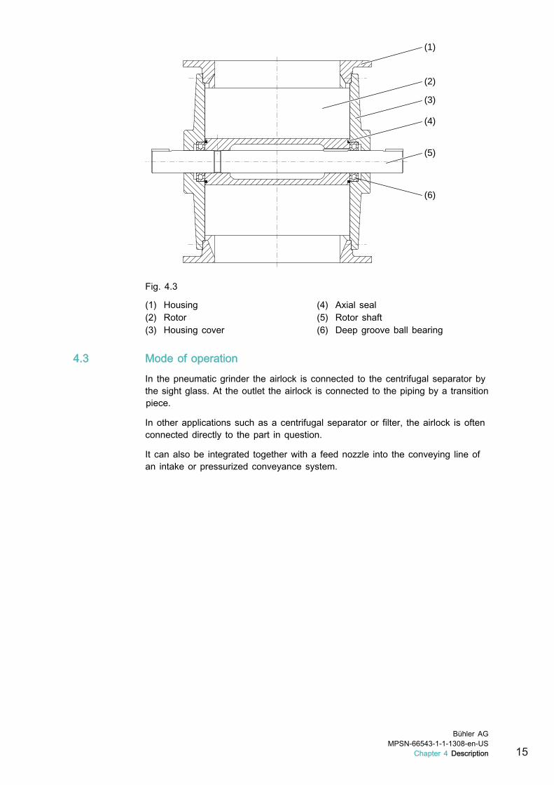
Fig. 4.3
(1) Housing (4) Axial seal(2) Rotor (5) Rotor shaft(3) Housing cover (6) Deep groove ball bearing
4.3 Mode of operation
In the pneumatic grinder the airlock is connected to the centrifugal separator bythe sight glass. At the outlet the airlock is connected to the piping by a transitionpiece.
In other applications such as a centrifugal separator or filter, the airlock is oftenconnected directly to the part in question.
It can also be integrated together with a feed nozzle into the conveying line ofan intake or pressurized conveyance system.
Bühler AGMPSN-66543-1-1-1308-en-US
Chapter 4 Description 15

(1)
(2)
(3)
Fig. 4.4
The bulk material enters the airlock through the inlet (1). It is captured by therotor (2) and guided to the outlet (3).
4.4 EMERGENCY STOP■ The EMERGENCY STOP button is integrated in the system control unit.■ The machine is stopped when the EMERGENCY STOP is triggered.■ Only trigger the EMERGENCY STOP to prevent imminent injury or damage
to property.
4.5 Protection devices■ The airlock must be integrated in the system such that people cannot reach
into the area near the rotor on either the inlet or outlet side. This is achievedusing permanently screwed-down inlet and outlet channels.
■ A lockable safety switch is present, and personnel have the matching pad-lock.
4.6 Safety symbols■ The "Move safety switch to “0” and lock" sign is affixed to the system.■ Service covers located less than 850 mm away from the rotor feature a “Do
not reach in” prohibition sign.
16Bühler AGMPSN-66543-1-1-1308-en-USChapter 4 Description

Fig. 4.5 Airlock with drive
Bühler AGMPSN-66543-1-1-1308-en-US
Chapter 4 Description 17

5 Transport
5.1 Packaging symbols
(1) (2) (4)(3) (5)
Fig. 5.1 Packaging symbols
(1) Top (4) Fragile(2) Protect against moisture (5) Attach here(3) Center of gravity
► Note packaging symbols.
5.2 Checking delivery
► Check for completeness of delivery according to the delivery note.► Report any missing parts or transport damage. See page 5, chapter “Con-
tact”.
5.3 Temporary storage
► Note packaging symbols.► Leave the machine and machine parts in the original packaging until starting
assembly work.► Do not store the machine outdoors.► Protect the machine from the effects of weather.► Prevent temperature fluctuations.
18Bühler AGMPSN-66543-1-1-1308-en-USChapter 5 Transport
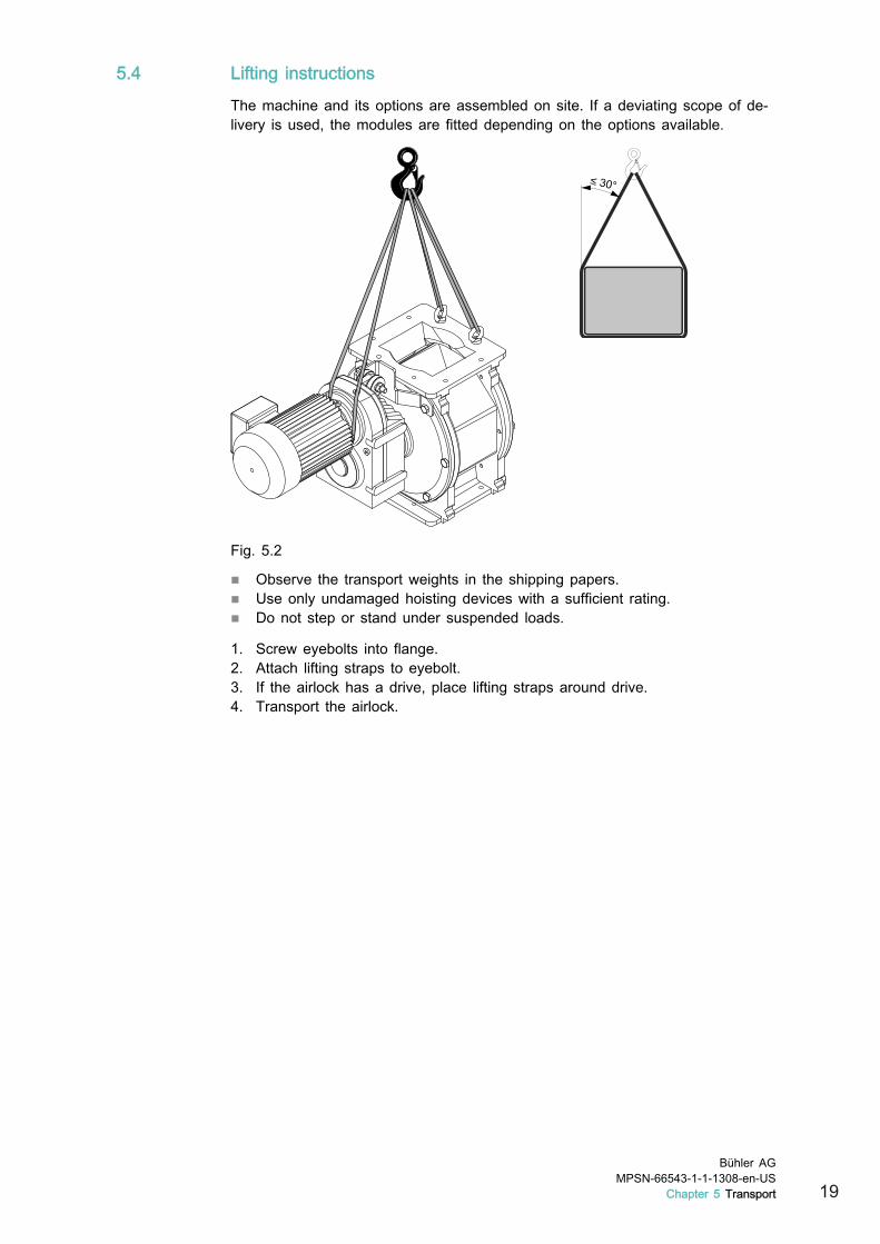
5.4 Lifting instructions
The machine and its options are assembled on site. If a deviating scope of de-livery is used, the modules are fitted depending on the options available.
Fig. 5.2
■ Observe the transport weights in the shipping papers.■ Use only undamaged hoisting devices with a sufficient rating.■ Do not step or stand under suspended loads.
1. Screw eyebolts into flange.2. Attach lifting straps to eyebolt.3. If the airlock has a drive, place lifting straps around drive.4. Transport the airlock.
Bühler AGMPSN-66543-1-1-1308-en-US
Chapter 5 Transport 19
6 Installation
6.1 Preparing installation location
850
mm
850
mm
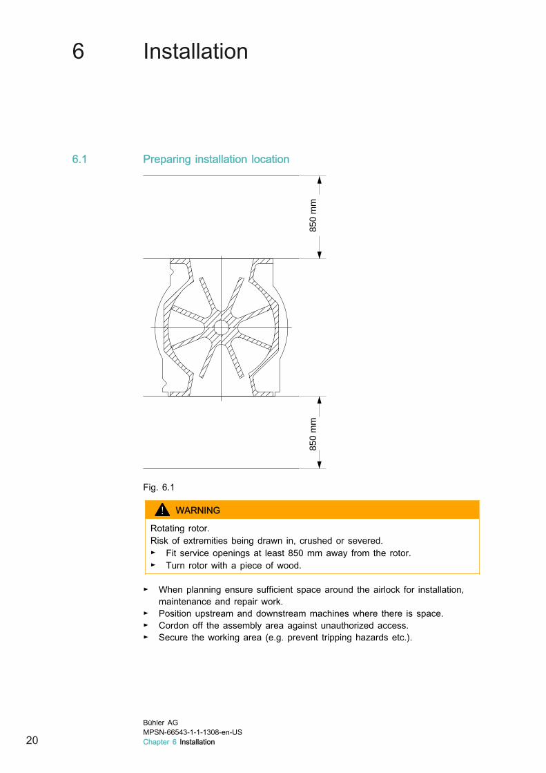
Fig. 6.1
WARNING
Rotating rotor.Risk of extremities being drawn in, crushed or severed.► Fit service openings at least 850 mm away from the rotor.► Turn rotor with a piece of wood.
► When planning ensure sufficient space around the airlock for installation,maintenance and repair work.
► Position upstream and downstream machines where there is space.► Cordon off the assembly area against unauthorized access.► Secure the working area (e.g. prevent tripping hazards etc.).
20Bühler AGMPSN-66543-1-1-1308-en-USChapter 6 Installation

6.2 Series arrangement
Airlock series on airlock table.
(1) (2) (3)
(4)
(5) (2) (3)
(4)
Fig. 6.2
(1) Spur gear (4) Clamping bracket(2) Coupling (5) Shaft-mounted gear unit(3) Bearing cover
Important
► Align axle horizontally and mount airlock in deenergized system.
1. Ensure there is sufficient space around airlocks and intermediate shafts.→ The coupling must function correctly.
2. Fit airlock.3. Mount clamping bracket.4. Mount bearing cover.5. Where a spur gear is fitted, align and mount airlocks from drive side.6. Where slip-on gear unit is fitted, align and mount airlocks from both sides.
6.3 Connecting the utilities
6.3.1 Electrical systems
► Fit overload protection upstream of drive motor. This may take the form of amotor protection switch or a contactor with thermal overload trigger.
► Near the airlock, install a lockable safety switch which can be used to fullydisconnect the drive motor from the electrical supply (provided by customer).→ This ensures that the drive is blocked in the event of maintenance and
repair work.
► Check that the rotor is turning in the right direction.
Bühler AGMPSN-66543-1-1-1308-en-US
Chapter 6 Installation 21

► To change the direction of rotation, swap the two phases in the terminal box.The direction of rotation is changed in the frequency converter by swappingthe corresponding phases.
► Ensure that the bulk material is flowing freely. If connecting to an intake orpressurized conveyance system, first switch on the blower for the convey-ance air and then the drive for the airlock.
► If available: Install speed monitoring device in plant control system.
Earthing
(1)(1)
Fig. 6.3
Connect all earthing connections and check for electrostatic charging by theproduct being conveyed.
Earthing in the piping is ensured by earthing the system. Ensure conductivity forscrewed/bolted connections with contact washers or copper strands.
Check:
■ Inspect the screw unions.■ Resistance across butt joints may not exceed 10 ohms. If resistance ex-
ceeds 10 ohms, restore electrical conductivity.
Safety switch
► Fit a lockable safety switch with a performance level (PL) “c” according toISO 13849-1 near the machine.
► Note local specifications.
22Bühler AGMPSN-66543-1-1-1308-en-USChapter 6 Installation
7 Commissioning
7.1 Checking commissioning
No. Check ✓1 There are no foreign objects in the machine.
2 Rotor is freely rotating. See page 23, chapter “Checking the ro-tor”.
3 All transport aids and assembly fixings have been removed.
4 Product feed and discharge are present and connected correctly.
5 Electrical connections and connection voltages correspond tospecifications on sign.
6 All electrical terminal boxes and plug sockets are closed.
7 Machine is earthed.
8 Airlock is turning in correct direction.
9 All controls and warning systems are functional.
10 A lockable safety switch is present, and personnel have a match-ing padlock.
11 The EMERGENCY STOP button is working.
12 All screwed/bolted connections have been properly tightened.
13 The gearmotor is filled with lubricant.
14 All connections for the lines are leak tight.
15 A safety valve has been provided for pneumatic conveyance sys-tems. The maximum pressure depends on the form of conveyanceand must be observed.
16 Warning signs are fitted to the side of the housing.
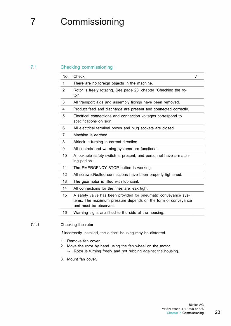
7.1.1 Checking the rotor
If incorrectly installed, the airlock housing may be distorted.
1. Remove fan cover.2. Move the rotor by hand using the fan wheel on the motor.
→ Rotor is turning freely and not rubbing against the housing.
3. Mount fan cover.
Bühler AGMPSN-66543-1-1-1308-en-US
Chapter 7 Commissioning 23

7.2 Conformity
7.2.1 Checking EC conformity
Operate the machine in the European Union only if EC conformity has beenchecked and confirmed using the following checklist.
Checklist
No. Check ✓1 The operator has been informed that the operating instructions
must be accessible to the personnel at all times.
2 The operator is responsible for instructing the personnel.
3 Assembly and installation have been carried out in accordancewith the operating instructions.
4 Machine has been connected and checked by an electrician. Allconnection sockets and boxes are properly closed.
5 Warnings and signs are attached so they are clearly visible.
6 A lockable safety switch has been fitted. Personnel are in posses-sion of the padlock for this.
7 Components on the inlet and outlet side can only be removed witha tool. This prevents access to the machine's moving parts.
8 Inspection covers fitted on the system are at least 850 mm away
from danger areas or fitted with a prohibition sign:
24Bühler AGMPSN-66543-1-1-1308-en-USChapter 7 Commissioning

8 Operation
8.1 Starting and stopping■ The machine is started and stopped using a superordinate system control
unit.■ The EMERGENCY STOP button is integrated in the system control unit.■ The machine is stopped as soon as the EMERGENCY STOP button is trig-
gered.
8.1.1 Starting
1. Ensure that the bulk material is flowing freely.2. If connecting to an intake or pressurized conveyance system, first switch on
the blower for the conveyance air and then the drive for the airlock.3. Start airlock.4. Supply product.
8.1.2 Stopping
1. Interrupt product feed.2. Wait until airlock is free of product.3. Stop airlock.
8.2 Checks during operation
► Regularly check the elements.→ This allows you to detect faults early on and initiate any actions required.
► Check bearing temperature.► Check seal integrity (traces of conveyed product or air leaking).
Bühler AGMPSN-66543-1-1-1308-en-US
Chapter 8 Operation 25

9 Trouble-shooting
9.1 Faults
Fault Cause RemedyThroughput toolow.
Insufficient bulk material feed. ► Check feed.
Speed too low. ► Increase speed up to maximum oflimit speed.
Insufficient feeding. ► Improve feeding or adjust feedingflap.
Product deposits on rotor. ► Clean rotor.
Irregular running. Defective bearing. ► Check bearing and replace if nec-essary.
Rotor blocked. Foreign objects in airlock. ► Remove and maintain rotor.
Temperatures or differences in tem-perature too high.
► Increase clearance.► Insulate or heat airlock.
Airlock not start-ing.
Defect in machine or plant control sys-tem.
► See operating instructions for con-trol system.
Gearmotor not connected. ► Correctly connect gearmotor.
Gearmotor overheating. ► Allow gearmotor to cool and rectifywhatever is causing it to overheat.
Gearmotor ther-mally overload-ed.
Excessive product friction. Occurs withmelted product.
► Clean airlock.► Cool product.► Enlarge rotor and slope rotor
blades.
Bearing hot. ► Replace bearing.
Product leakingout at rotorshaft.
Rotor seal not tight. ► Remove and clean seal.► If defective, replace seal.
Bearing shaft seal not tight. ► Replace bearing.
Lubricant on ro-tor shaft.
Bearing shaft seal not tight. ► Remove and clean seal.► If defective, replace seal.
Oil on gearmo-tor.
Gear leaking. ► Replace seals in gearmotor.
Ventilation positioned incorrectly. ► Correct position. Refer to the doc-umentation supplied by the gear-motor manufacturer.
26Bühler AGMPSN-66543-1-1-1308-en-USChapter 9 Trouble-shooting

10 Maintenance
CAUTION
Conveyed product may be blown out when opening the airlock.Eye injuries.► Only open or disassemble airlocks if the system is depressurized and the
pressure system is protected against being switched on by locking theassociated safety switch.
10.1 Cleaning
The cleaning intervals depend on the product, location and climate and have tobe determined by the user.
► Keep airlock clean. Remove dust, dirt or product deposits.► Always clean dry with cloths, brush or vacuum cleaner.► If dirty, clean the fan cover's intake apertures and the cooling fins on the
electric motor.► If changing product, clean rotor and other cavities.
10.2 Lubrication
10.2.1 Lubrication schedule
Interval Machine part Dura-tion
Measure
500 h /once amonth
Gearmotor __:__ ► Check the oil level. Top up ifnecessary.
10.2.2 Bearing
The bearings in the airlock have lifetime lubrication with lubricant of classNSF H1 as defined by the FDA. The bearing seals prevent grease from leakingout and becoming contaminated. When the grease is used up, replace bearing.Minimum lifetime of bearings: 30,000 hours.
Bühler AGMPSN-66543-1-1-1308-en-US
Chapter 10 Maintenance 27

10.3 Maintenance
10.3.1 Maintenance schedule
Interval Machine part Dura-tion
Measure
Frequency convert-er
__:__ ► Refer to the manufacturer'sdocumentation.
120 h /once aweek
Bearing seal __:__ ► If product, air or grease is es-caping at rotor shaft, checkbearing seal for wear and re-place if there are signs ofwear.
10.3.2 Maintaining airlock
(2)
(3)
(1)
(5)
(4)
(6)(7)
(1)
Fig. 10.1
Dismantling airlock
1. Stop the machine.2. Set safety switch to “0” and lock it.3. Switch off product feed and rinse air/conveyance air.4. If necessary, first remove the drive or speed monitoring.5. Remove coupling halves and keys (1).6. Release screws (2) from housing cover (3).7. Remove housing cover from shaft (5) of rotor.8. If necessary, loosen grub screw (7) to separate rotor and shaft.9. Leave bearing on shaft or in cover.10. Check and clean following parts.
► Remove axial groove rings, check for damage and clean grooves.► Clean surface of shaft.► Check and clean bearing, replace if necessary.► Replace worn or damaged parts.► If there is insufficient grease in bearing, replace bearing.
28Bühler AGMPSN-66543-1-1-1308-en-USChapter 10 Maintenance

Assembling airlock
1. Assemble rotor and shaft with setscrew.► Ensure that rotor is easy to turn by hand.► Do not distort bearing.
2. Press housing cover onto rotor's shaft.3. Install coupling halves and key.4. Install drive and speed monitoring.5. Check the rotor. See page 23, chapter “Checking the rotor”.
Bühler AGMPSN-66543-1-1-1308-en-US
Chapter 10 Maintenance 29

11 Maintenance and repair
11.1 Replace speed sensor
11.1.1 Removing speed sensor
1. Stop the machine.2. Set safety switch to “0” and lock it.3. Switch off product feed and rinse air.4. Separate electric plug (2) from sensor.
(1) (2)
5. Remove 3 screws and lid (1).6. Release counter nut (4).
(3) (4) (5)
7. Remove nut (3) and speed sensor (5).
30Bühler AGMPSN-66543-1-1-1308-en-USChapter 11 Maintenance and repair

8. Perform the following work if necessary.
(6) (7)
► Loosen screw (7) and remove housing (6).
9. Loosen setscrew (8) and remove contact tab (9) from shaft.
(9)
(8)
Bühler AGMPSN-66543-1-1-1308-en-US
Chapter 11 Maintenance and repair 31

11.1.2 Installing speed sensor
1. Slide contact tab (2) onto shaft.
(2)
(1)
► Do not tighten setscrew (1).
2. Secure housing (3) to machine with screw (4).
(3) (4)(2) (2)
3. Center contact tab (2) in threaded hole.4. Tighten setscrew (1) to contact tab.
→ Contact tab is fixed.
32Bühler AGMPSN-66543-1-1-1308-en-USChapter 11 Maintenance and repair

5. Insert speed sensor (7).
(5) (6) (7)
6. Use nut (5) to set distance between speed sensor and contact tab.► Distance between speed sensor and contact tab: 1 … 5 mm
7. Tighten counter nut (6).8. Ensure that contact tab cannot touch speed sensor.9. Secure lid (8) to housing with 3 screws.
(8) (9)
10. Connect electric plug (9) with sensor.
Bühler AGMPSN-66543-1-1-1308-en-US
Chapter 11 Maintenance and repair 33
11.2 Replacing bearing and shaft seal
(1)
(2)
(4)
(3)
(5)
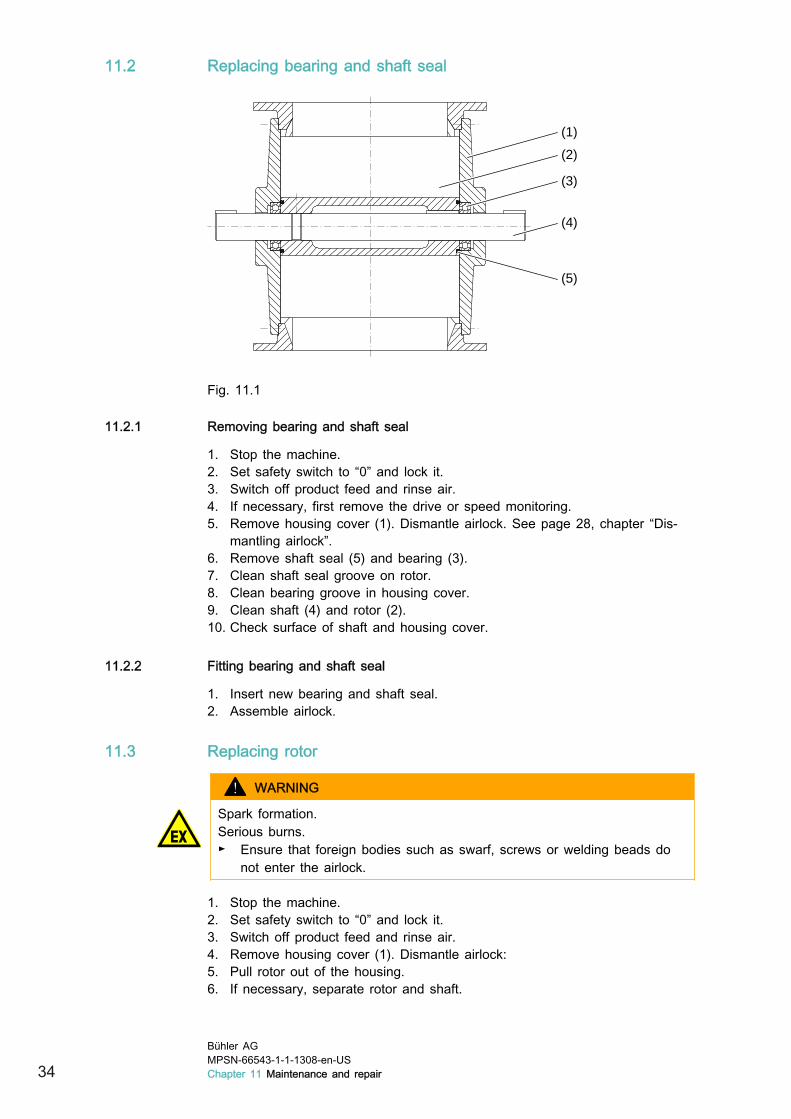
Fig. 11.1
11.2.1 Removing bearing and shaft seal
1. Stop the machine.2. Set safety switch to “0” and lock it.3. Switch off product feed and rinse air.4. If necessary, first remove the drive or speed monitoring.5. Remove housing cover (1). Dismantle airlock. See page 28, chapter “Dis-
mantling airlock”.6. Remove shaft seal (5) and bearing (3).7. Clean shaft seal groove on rotor.8. Clean bearing groove in housing cover.9. Clean shaft (4) and rotor (2).10. Check surface of shaft and housing cover.
11.2.2 Fitting bearing and shaft seal
1. Insert new bearing and shaft seal.2. Assemble airlock.
11.3 Replacing rotor
WARNING
Spark formation.Serious burns.► Ensure that foreign bodies such as swarf, screws or welding beads do
not enter the airlock.
1. Stop the machine.2. Set safety switch to “0” and lock it.3. Switch off product feed and rinse air.4. Remove housing cover (1). Dismantle airlock:5. Pull rotor out of the housing.6. If necessary, separate rotor and shaft.
34Bühler AGMPSN-66543-1-1-1308-en-USChapter 11 Maintenance and repair

7. Insert new rotor.8. Assemble airlock. See page 29, chapter “Assembling airlock”.9. Check rotor. See page 23, chapter “Checking the rotor”.
Bühler AGMPSN-66543-1-1-1308-en-US
Chapter 11 Maintenance and repair 35
12 Decommissioning
12.1 Dismantle
Once work with the machine is complete (inspection, removal or disposal), themachine is disassembled in reverse order to the assembly process.
► Before starting the disassembly process, the person who is responsible mustobtain instructions from the manufacturer for safe disassembly.
► The machine may only be disassembled in accordance with all accident pre-vention measures and only by instructed personnel. This personnel must befamiliar with the safety precautions.
12.2 Disposal
12.2.1 Disposal of operating materials
► Remove operating materials completely from the machine and dispose ofthem properly in accordance with the local legal requirements.
12.2.2 Disposing of machine
1. Dismantle machine into its components.2. Sort components according to materials and dispose of them in compliance
with local applicable laws and regulations.
36Bühler AGMPSN-66543-1-1-1308-en-USChapter 12 Decommissioning


Bühler AGCH-9240 Uzwil, Schweiz+41 71 955 11 11+41 71 955 33 79www.buhlergroup.com