
Operating instructions Discharge airlock MPSJ-66481-1 … · MPSJ-LP 45/45 61.7 dm3 MPSJ-LP 60/60...
46
Operating instructions Discharge airlock MPSJ-LP MPSJ-LP-Ex MPSJ-66481-1-en-gb
Transcript of Operating instructions Discharge airlock MPSJ-66481-1 … · MPSJ-LP 45/45 61.7 dm3 MPSJ-LP 60/60...

Operating instructions Discharge airlockMPSJ-LPMPSJ-LP-Ex
MPSJ-66481-1-en-gb

Copyright by Bühler AGOriginal operating instructionsTotal no. of pages 462010-08-30

Table of contents
1 Important Information 61.1 Scope of validity 61.2 Applicable documents 61.3 Contact 6
1.3.1 Address 61.4 Personnel Qualification 7
1.4.1 Fitter 71.4.2 Electrician 71.4.3 Welders 7
1.5 Symbol Conventions 71.5.1 Explanation of the warning signs 7
2 Safety 82.1 Intended use 82.2 Technical Condition 82.3 ATEX designation 82.4 Personnel Qualification 82.5 Safety Devices 92.6 Safety warning notices 92.7 Safe Working Environment 9
2.7.1 Slipping and tripping hazard 9
3 Technical data 103.1 Performance characteristics 10
3.1.1 Maximum permissible torque 103.1.2 Rotor volume 10
3.2 Operating temperature 113.3 Pneumatic system 123.4 Dimension sheet 12
3.4.1 Available versions 133.5 Transport weights and volumes 143.6 Sound data 143.7 Options 14
3.7.1 MOVIMOT® option 143.7.2 MOVIMOT® 153.7.3 Frequency converter TRIO SK300E 16
3.8 Compressed air 17
4 Description 184.1 Identification 18
4.1.1 Nameplate 184.1.2 Type code 184.1.3 ATEX marking for use in Ex zone 22 184.1.4 ATEX marking without approval for use in potentially ex-
plosive zones19
4.2 Overview 19
Bühler AGMPSJ-66481-1-en-gb
Table of contents 3

4.3 Function 204.4 EMERGENCY STOP 214.5 Safety devices 214.6 Safety warning notices 21
5 Transport 225.1 Packaging mark 225.2 Checking delivery 225.3 Temporary storage 225.4 Lifting instructions 22
6 Assembly 246.1 Preparing the setup location 246.2 Installation 256.3 Connecting supplies 25
6.3.1 Electrical systems 256.3.2 Compressed air 26
7 Commissioning 277.1 Checking commissioning 277.2 Conformity 28
7.2.1 Checking EC conformity 287.3 Test run 28
8 Operation 298.1 Starting and stopping 29
8.1.1 Starting 298.1.2 Stopping 29
8.2 Checks during operation 29
9 Fault Clearance 309.1 Faults 30
10 Maintenance 3110.1 Cleaning 3110.2 Lubrication 31
10.2.1 Lubrication schedule 3210.2.2 Grease volumes 32
10.3 Maintenance 3210.3.1 Maintenance schedule 32
11 Maintenance and repair 3311.1 Removing adjustment cover 3311.2 Removing housing cover 3311.3 Replacing rotary valve 3411.4 Repairing rotary valve shaft 3411.5 Replacing bearing shaft seals 3511.6 Replacing product and air shaft seals 3511.7 Replacing rotational speed sensor 36
12 Removal from Service 3712.1 Dismantling 3712.2 Disposal 37
4Bühler AGMPSJ-66481-1-en-gbTable of contents

13 Spare parts 3813.1 Spare parts stock 3813.2 Ordering instructions 3813.3 Spare part identification 3813.4 Spare parts lists 39
13.4.1 MPSJ-LP 18/15 3913.4.2 MPSJ-LP 22/22 4013.4.3 MPSJ-LP 28/30 4113.4.4 MPSJ-LP 36/38 4213.4.5 MPSJ-LP 45/45 4313.4.6 MPSJ-LP 60/60 44
Bühler AGMPSJ-66481-1-en-gb
Table of contents 5
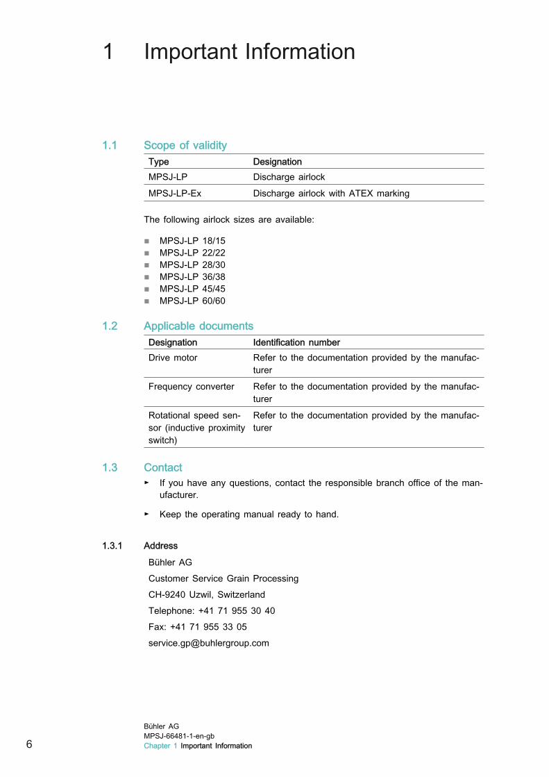
1 Important Information
1.1 Scope of validityType DesignationMPSJ-LP Discharge airlock
MPSJ-LP-Ex Discharge airlock with ATEX marking
The following airlock sizes are available:
■ MPSJ-LP 18/15■ MPSJ-LP 22/22■ MPSJ-LP 28/30■ MPSJ-LP 36/38■ MPSJ-LP 45/45■ MPSJ-LP 60/60
1.2 Applicable documentsDesignation Identification numberDrive motor Refer to the documentation provided by the manufac-
turer
Frequency converter Refer to the documentation provided by the manufac-turer
Rotational speed sen-sor (inductive proximityswitch)
Refer to the documentation provided by the manufac-turer
1.3 Contact► If you have any questions, contact the responsible branch office of the man-
ufacturer.
► Keep the operating manual ready to hand.
1.3.1 Address
Bühler AGCustomer Service Grain ProcessingCH-9240 Uzwil, SwitzerlandTelephone: +41 71 955 30 40Fax: +41 71 955 33 [email protected]
6Bühler AGMPSJ-66481-1-en-gbChapter 1 Important Information

1.4 Personnel Qualification1.4.1 Fitter
Persons who work on mechanical equipment must be technically qualified orhave competed training by the manufacturer.
1.4.2 ElectricianPersons who work on electrical equipment must be technically qualified or havecompeted training by the manufacturer.
1.4.3 WeldersPersonnel who weld on the fixtures must have specialised training
1.5 Symbol Conventions1.5.1 Explanation of the warning signs
DANGER
Type and source of the hazardThe hazard results in death or severe injuries.► Measures for protection against the hazard.
WARNING
Type and source of the hazardThe hazard can result in death or severe injuries.► Measures for protection against the hazard.
CAUTION
Type and source of the hazardThe hazard can result in injuries.► Measures for protection against the hazard.
NOTICE
Type and source of the hazardThe hazard can result in property damage.► Measures for protection against property damage.
Bühler AGMPSJ-66481-1-en-gb
Chapter 1 Important Information 7
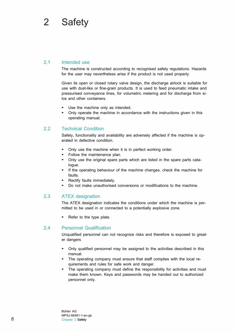
2 Safety
2.1 Intended useThe machine is constructed according to recognised safety regulations. Hazardsfor the user may nevertheless arise if the product is not used properly.
Given its open or closed rotary valve design, the discharge airlock is suitable foruse with dust-like or fine-grain products. It is used to feed pneumatic intake andpressurised conveyance lines, for volumetric metering and for discharge from si-los and other containers.
► Use the machine only as intended.► Only operate the machine in accordance with the instructions given in this
operating manual.
2.2 Technical ConditionSafety, functionality and availability are adversely affected if the machine is op-erated in defective condition.
► Only use the machine when it is in perfect working order.► Follow the maintenance plan.► Only use the original spare parts which are listed in the spare parts cata-
logue.► If the operating behaviour of the machine changes, check the machine for
faults.► Rectify faults immediately.► Do not make unauthorised conversions or modifications to the machine.
2.3 ATEX designationThe ATEX designation indicates the conditions under which the machine is per-mitted to be used in or connected to a potentially explosive zone.
► Refer to the type plate.
2.4 Personnel QualificationUnqualified personnel can not recognize risks and therefore is exposed to great-er dangers
► Only qualified personnel may be assigned to the activities described in thismanual.
► The operating company must ensure that staff complies with the local re-quirements and rules for safe work and danger.
► The operating company must define the responsibility for activities and mustmake them known. Keys and passwords may be handed out to authorizedpersonnel only.
8Bühler AGMPSJ-66481-1-en-gbChapter 2 Safety

2.5 Safety DevicesPeople are endangered if safety devices are not effective.
► Ensure that all safety devices are functioning before operating the machine.
2.6 Safety warning noticesIf safety warning notices are not legible, people are at risk.
► Replace illegible safety warning notices.► Do not remove or cover safety warning signs.
2.7 Safe Working Environment2.7.1 Slipping and tripping hazard
Slippery surfaces and tripping hazards can result in serious accidents.
► Keep gangways, handles, steps, railings, pedestals and ladders free ofgrease, oil and other soiling.
► Do not use the machine as a climbing aid or storage place. Only use thesteps and pedestals provided.
► Wear anti-slip safety shoes.
Bühler AGMPSJ-66481-1-en-gb
Chapter 2 Safety 9

3 Technical data
3.1 Performance characteristics3.1.1 Maximum permissible torque
Description Value UnitMPSJ-LP 18/15 150 Nm
MPSJ-LP 22/22 415 Nm
MPSJ-LP 28/30 425 Nm
MPSJ-LP 36/38 910 Nm
MPSJ-LP 45/45 910 Nm
MPSJ-LP 60/60 1720 Nm
3.1.2 Rotor volumeDesign with open rotary valve
Description Value UnitMPSJ-LP 18/15 2.5 dm3
MPSJ-LP 22/22 6.1 dm3
MPSJ-LP 28/30 13.8 dm3
MPSJ-LP 36/38 30.7 dm3
MPSJ-LP 45/45 60.1 dm3
MPSJ-LP 60/60 143.8 dm3
10Bühler AGMPSJ-66481-1-en-gbChapter 3 Technical data

Design with closed rotary valve
Description Value UnitMPSJ-LP 18/15 2.6 dm3
MPSJ-LP 22/22 6.4 dm3
MPSJ-LP 28/30 14.3 dm3
MPSJ-LP 36/38 31.6 dm3
MPSJ-LP 45/45 61.7 dm3
MPSJ-LP 60/60 146.5 dm3
3.2 Operating temperatureThe following versions are available for various operating temperatures. Selectthe relevant version depending on the greatest difference in temperature be-tween the housing and rotary valve and depending on whether insulation is nee-ded (accident protection).
Description Value UnitFor low-temperature bulk material Up to 60 °C
ΔTmax (rotary valve housing) 20 °C
Description Value UnitFor high-temperature bulk material Up to 140 °C
ΔTmax 40 °C
Description Value UnitFor bulk material of higher temperatures (onlyin version with closed rotary valves)
Up to 220 °C
ΔTmax 60 °C
Bühler AGMPSJ-66481-1-en-gb
Chapter 3 Technical data 11

3.3 Pneumatic system
Description Value UnitMaximum operating pressure 1.5 bar
3.4 Dimension sheet
:Item-Nr.
Buehler GmbH, Ernst-Amme-Strasse 19D-38023 Braunschweig
mm
Typ :
:
:
:
Baujahr
Masch.-Nr.
Spiel im ø
M
øH h
7
K
C
F
G
f
e
LL
II
B
A
MPSJ-LP 60/60
MPSJ-LP 36/38,45/45MPSJ-LP 18/15,22/22,28/30
R
T
Y Sa U
X3xZ
Y
R
a ST
X
U
2xZ
R
Y
T
a S
X
U
Z
E
D
d
Type MPSJ 18/15 22/22 28/30 36/38 45/45 60/60A 280 320 410 480 580 800
B 135 160 205 240 290 400
C 531 629 718 861 931 1218
D 8 10 10 12 12 14
E 28 38.3 38.3 43.3 43.3 53.8
12Bühler AGMPSJ-66481-1-en-gbChapter 3 Technical data

Type MPSJ 18/15 22/22 28/30 36/38 45/45 60/60F 303 366 411 500 535 695
G 97 105 106 141 141 174
H 40 35 35 40 40 50
I 140 154 185 225 275 370
K 128 200 270 350 408 566
L 75 80 95 105 150 200
M 12 12 15 15 18 28
R 210 280 370 450 512 686
S 210 250 320 350 410 520
T 130 200 270 350 408 566
U 130 150 220 250 306 400
X 180 250 335 420 476 636
Y 180 220 285 320 374 470
Z 100 150 200 300 320 450
a 100 100 200 180 220 300
d 11 11 13.5 13.5 13.5 17.5
e M16 M16 M16 M16 M20 M20
f 62.5 81
3.4.1 Available versions
B
On left: version for direct assembly on the floor. Right: with additional feet. Fig. 3.4
MPSJ-LP A B C D E F18/15 348 135 145 117 226 228
22/22 483 160 160 260 261 263
28/30 483 200 205 340 305 307
36/38 563 240 240 440 359 361
45/45 563 290 290 500 394 396
60/60 665 400 400 640 521 523
Bühler AGMPSJ-66481-1-en-gb
Chapter 3 Technical data 13
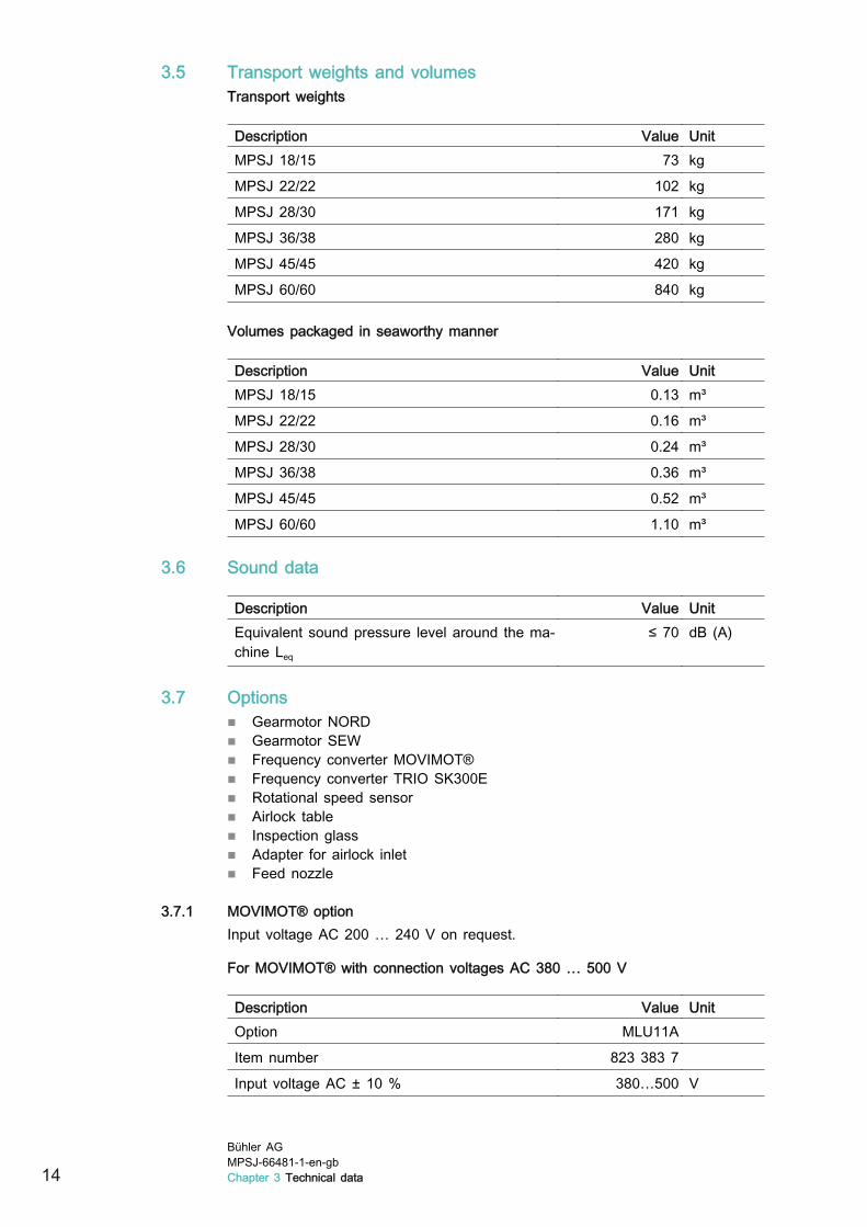
3.5 Transport weights and volumesTransport weights
Description Value UnitMPSJ 18/15 73 kg
MPSJ 22/22 102 kg
MPSJ 28/30 171 kg
MPSJ 36/38 280 kg
MPSJ 45/45 420 kg
MPSJ 60/60 840 kg
Volumes packaged in seaworthy manner
Description Value UnitMPSJ 18/15 0.13 m³
MPSJ 22/22 0.16 m³
MPSJ 28/30 0.24 m³
MPSJ 36/38 0.36 m³
MPSJ 45/45 0.52 m³
MPSJ 60/60 1.10 m³
3.6 Sound data
Description Value UnitEquivalent sound pressure level around the ma-chine Leq
≤ 70 dB (A)
3.7 Options■ Gearmotor NORD■ Gearmotor SEW■ Frequency converter MOVIMOT®■ Frequency converter TRIO SK300E■ Rotational speed sensor■ Airlock table■ Inspection glass■ Adapter for airlock inlet■ Feed nozzle
3.7.1 MOVIMOT® optionInput voltage AC 200 … 240 V on request.
For MOVIMOT® with connection voltages AC 380 … 500 V
Description Value UnitOption MLU11A
Item number 823 383 7
Input voltage AC ± 10 % 380…500 V
14Bühler AGMPSJ-66481-1-en-gbChapter 3 Technical data

Description Value UnitOutput voltage DC 24 V ± 25 % V
Output current 250 mA
Protection type IP65
3.7.2 MOVIMOT®UL versions and input voltage AC 200 … 240 V on request.
Description Value UnitConnection voltages AC 3 x 380 / 400 /
415 /460 /500V
Permissible range of Umains AC (+/‑10 %) 380 … 500 V
Mains frequency (+/‑10 %) 50 … 60 Hz
Output voltage 0 … Umains V
Output frequency 2 … 100 Hz
Resolution 0.01 Hz
Operating point at 50 Hz / 100 Hz 400 V
MM 03B-503-00
Description Value UnitItem number 823 022 6
Output rating when Umains = 380 … 500 V 1.1 kVA
Nominal mains current 1.3 A
Nominal output current 1.6 A
Motor rating 0.37 kW
MM 05B-503-00
Description Value UnitItem number 823 023 4
Output rating when Umains = 380 … 500 V 1.4 kVA
Nominal mains current 1.6 A
Nominal output current 2.0 A
Motor rating 0.55 kW
MM 07B-503-00
Description Value UnitItem number 823 024 2
Output rating when Umains = 380 … 500 V 1.8 kVA
Nominal mains current 1.9 A
Nominal output current 2.5 A
Motor rating 0.75 kW
Bühler AGMPSJ-66481-1-en-gb
Chapter 3 Technical data 15
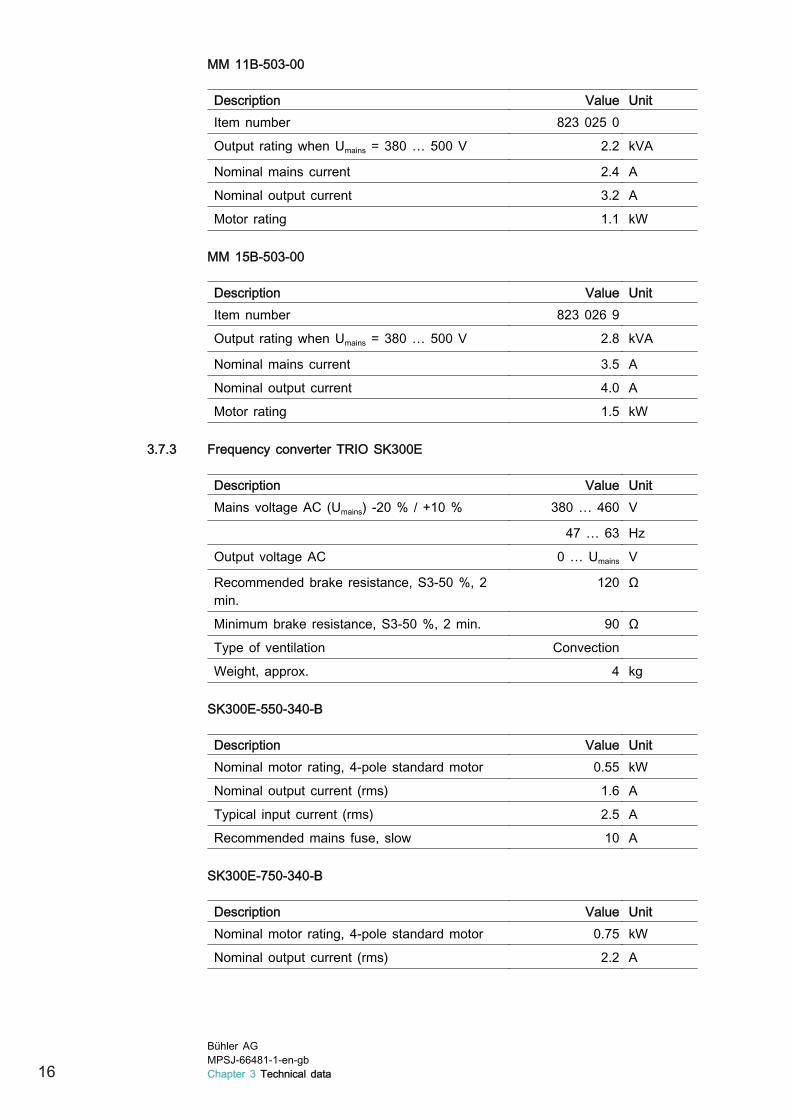
MM 11B-503-00
Description Value UnitItem number 823 025 0
Output rating when Umains = 380 … 500 V 2.2 kVA
Nominal mains current 2.4 A
Nominal output current 3.2 A
Motor rating 1.1 kW
MM 15B-503-00
Description Value UnitItem number 823 026 9
Output rating when Umains = 380 … 500 V 2.8 kVA
Nominal mains current 3.5 A
Nominal output current 4.0 A
Motor rating 1.5 kW
3.7.3 Frequency converter TRIO SK300E
Description Value UnitMains voltage AC (Umains) ‑20 % / +10 % 380 … 460 V
47 … 63 Hz
Output voltage AC 0 … Umains V
Recommended brake resistance, S3‑50 %, 2min.
120 Ω
Minimum brake resistance, S3‑50 %, 2 min. 90 Ω
Type of ventilation Convection
Weight, approx. 4 kg
SK300E-550-340-B
Description Value UnitNominal motor rating, 4-pole standard motor 0.55 kW
Nominal output current (rms) 1.6 A
Typical input current (rms) 2.5 A
Recommended mains fuse, slow 10 A
SK300E-750-340-B
Description Value UnitNominal motor rating, 4-pole standard motor 0.75 kW
Nominal output current (rms) 2.2 A
16Bühler AGMPSJ-66481-1-en-gbChapter 3 Technical data

Description Value UnitTypical input current (rms) 3.1 A
Recommended mains fuse, slow 10 A
SK300E-111-340-B
Description Value UnitNominal motor rating, 4-pole standard motor 1.1 kW
Nominal output current (rms) 3.0 A
Typical input current (rms) 4.2 A
Recommended mains fuse, slow 10 A
SK300E-151-340-B
Description Value UnitNominal motor rating, 4-pole standard motor 1.5 kW
Nominal output current (rms) 3.7 A
Typical input current (rms) 5.2 A
Recommended mains fuse, slow 10 A
3.8 Compressed airCompressed air consumption depends on the airlock. Used to rinse shafts withthe open rotary valve design.
Quality class acc. to DIN ISO 8573-1
Description Value UnitSolids 2
Water 3
Oil content 1
Input and pressure
Description Value UnitInput for type 18/15 G3/8 "
Input for all other types G1/2 "
Pressure from supply network 6 bar
Bühler AGMPSJ-66481-1-en-gb
Chapter 3 Technical data 17

4 Description
4.1 Identification4.1.1 Nameplate
The ATEX marking is only used on machines with approval for use in potentiallyexplosive zones.
Fig. 4.1
(1) Manufacturer (4) Machine number(2) Place of manufacture (5) Year of manufacture(3) Machine type (6) ATEX designation
4.1.2 Type codeMPSJ-LP 36/38-ExMPSJ → Code
LP → Low Pressure (pressure levels up to 1.5 bar)
36 → Rotary valve diameter in cm
38 → Rotary valve length in cm
Ex → Approval for a potentially explosive zone
4.1.3 ATEX marking for use in Ex zone 22The ATEX designation indicates the conditions under which the machine is per-mitted to be used in a potentially explosive zone or connected to a potentiallyexplosive zone.
II */3D T=135 °C
Explanation of symbols:
— ATEX symbol
II — Device group
18Bühler AGMPSJ-66481-1-en-gbChapter 4 Description

II */3D T=135 °C
*/ — Internal category: no own internal ignition source
/3 — External category 3
D — Dust atmosphere
T — Maximum expected surface temperature in °C in normal operation atfull load and at an ambient temperature of 40 °C
4.1.4 ATEX marking without approval for use in potentially explosive zonesII */-D
Explanation of symbols:
→ ATEX symbol
II → Device group
*/ → Internal category: no own internal ignition source
/- → Not approved for use in potentially explosive zones
D → Dust atmosphere
4.2 OverviewThe discharge airlock is intended for metering and introducing free-flowing bulkmaterials to a pneumatic form of conveyance. It can also be used to separatetwo pressurised containers and therefore to inhibit an explosion from spreading.
If using toxic or explosive carrier gases and products, special, further protectivemeasures should be taken by the operator or customer (e.g. gas detectors, seal-ing gas).
The rotary valve is produced in an open and closed version. See illustrations be-low.
Open rotary valve Fig. 4.6
Bühler AGMPSJ-66481-1-en-gb
Chapter 4 Description 19

Closed rotary valve Fig. 4.7
(1) Rotary valve shaft (5) Housing cover(2) Roller bearing (6) Housing(3) Grease nipple (7) Open rotary valve(4) Shaft seals (8) Closed rotary valve
4.3 FunctionThe bulk material flowing to the inlet (1) is captured by the rotating rotary valve(2) and guided into the outlet (3). With a pressurised conveyance system, theairlock's bulk material is fed through a venting inlet box. This prevents air leak-ing from the airlock stirring up the product and resulting in throughput losses.The leaking air can be extracted by the inlet box or discharged to the surround-ings via a filter hose. Depending on the conveyance process, a feed nozzle con-nects the airlock with the conveying line.
2
1
3
MPSJ system Fig. 4.8
(1) Inlet(2) Rotary valve(3) Outlet
20Bühler AGMPSJ-66481-1-en-gbChapter 4 Description
4.4 EMERGENCY STOP■ The emergency stop button is integrated in the system control unit.■ The machine is stopped as soon as the emergency stop is triggered.■ Only trigger the emergency stop button to prevent imminent injury or dam-
age to property.
4.5 Safety devices■ The airlock must be integrated in the system such that people cannot reach
into the area near the rotor on either the inlet or outlet side. This is achievedusing permanently screwed down inlet and outlet channels.
■ A lockable safety switch is present, and the personnel have a matching pad-lock.
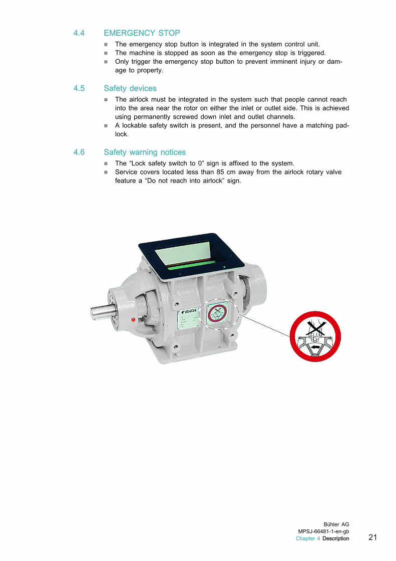
4.6 Safety warning notices■ The “Lock safety switch to 0” sign is affixed to the system.■ Service covers located less than 85 cm away from the airlock rotary valve
feature a “Do not reach into airlock” sign.
Bühler AGMPSJ-66481-1-en-gb
Chapter 4 Description 21

5 Transport
5.1 Packaging mark
Fig. 5.1
(1) Top (4) Fragile(2) Protect against moisture (5) Attach here(3) Centre of gravity
► Observe packaging mark.
5.2 Checking delivery► Check for completeness of delivery according to the delivery note.
► Report any missing parts and transport damage. See Chapter 1.3 “Contact”.
5.3 Temporary storage► Observe packaging mark.
► Leave the machine and machine parts in the original packaging until startingassembly work.
► Do not store the machine outdoors.
► Protect the machine from the effects of weather.
► Avoid temperature fluctuations.→ Temperature fluctuations cause corrosion due to condensation.
5.4 Lifting instructionsThe machine and its options are assembled on site. If a deviating scope of de-livery is used, the modules are fitted depending on the options available.
■ Observe the transport weights in the shipping papers.■ Check the crane and the lifting gear to make sure they have the required
design and are approved for the necessary load capacity.■ When lifting, only use the specified attachment points.■ Never step or remain under suspended loads.
1. Screw eyebolts into flange.
22Bühler AGMPSJ-66481-1-en-gbChapter 5 Transport

2. Attach lifting straps to eyebolt.
Bühler AGMPSJ-66481-1-en-gbChapter 5 Transport 23

6 Assembly
6.1 Preparing the setup location
850m
m85
0mm
DANGER
Rotating rotary valveRisk of body parts being drawn in, crushed or severed.► Fit service openings at least 850 mm away from the rotor.
24Bühler AGMPSJ-66481-1-en-gbChapter 6 Assembly
► When planning ensure sufficient space around the airlock for installation,maintenance and repair work.
► Position upstream and downstream machines where there is space.
► Cordon off the installation area so that no unauthorised persons have accessto it.
► Secure the working area (e.g. prevent tripping hazards etc.).
6.2 Installation
Important
► Ensure that the axle is fitted perfectly horizontally and that the airlock isnot energised.
1. Fit feet.► Lift the machine. See Chapter 5.4 “Lifting instructions”.► Screw feet to housing.
2. Lift machine up to installation site. See Chapter 5.4 “Lifting instructions”.
3. Draw on retaining holes.► Lift machine again and put to one side.
4. Drill holes.
5. Put machine back in assembly position.
6. Level the machine.► Adjust feet height.
7. Screw down.
6.3 Connecting supplies6.3.1 Electrical systems
► Fit overload protection upstream of drive motor. This may take the form of amotor protection switch or a contactor with thermal overload trigger.
► Near the airlock, install a lockable safety switch which can be used to fullydisconnect the drive motor from the electrical supply (provided by customer).→ This ensures that the drive is blocked in the event of maintenance and
repair work.
Bühler AGMPSJ-66481-1-en-gbChapter 6 Assembly 25

► Connect all grounding connections and check for electrostatic charging bythe product being conveyed.
► Check that the rotary valve is rotating in the specified direction (arrow indi-cating direction of rotation on housing).
► To change the direction of rotation, swap the two phases in the terminal box.The direction of rotation is changed in the frequency converter by swappingthe corresponding phases.
► Ensure that the bulk material is flowing freely. If connecting to an intake orpressurised conveyance system, first switch on the fan for the conveyanceair and then the drive for the airlock.
► If present: integrate rotational speed sensor in system control unit.
6.3.2 Compressed air
Important
► Fit the supply and discharge lines such that the airlock housing remainsde-energised.
26Bühler AGMPSJ-66481-1-en-gbChapter 6 Assembly
7 Commissioning
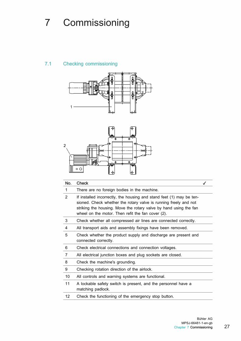
7.1 Checking commissioning
No. Check ✓1 There are no foreign bodies in the machine.
2 If installed incorrectly, the housing and stand feet (1) may be ten-sioned. Check whether the rotary valve is running freely and notstriking the housing. Move the rotary valve by hand using the fanwheel on the motor. Then refit the fan cover (2).
3 Check whether all compressed air lines are connected correctly.
4 All transport aids and assembly fixings have been removed.
5 Check whether the product supply and discharge are present andconnected correctly.
6 Check electrical connections and connection voltages.
7 All electrical junction boxes and plug sockets are closed.
8 Check the machine's grounding.
9 Checking rotation direction of the airlock.
10 All controls and warning systems are functional.
11 A lockable safety switch is present, and the personnel have amatching padlock.
12 Check the functioning of the emergency stop button.
Bühler AGMPSJ-66481-1-en-gb
Chapter 7 Commissioning 27
No. Check ✓13 All screw connections have been properly tightened.
14 All geared motors and bearings have been filled with lubricant.
15 All connections for the lines are leak tight.
16 A safety valve should be provided for pneumatic conveyance sys-tems. The specified pressure depends on the form of conveyanceand must be observed.
17 If using a gas-tight inlet box, ensure that the leaking air is notpressurised, i.e. can flow at a pressure of < 50 mbar.
18 Warning signs are fitted to the side of the housing.
7.2 Conformity7.2.1 Checking EC conformity
► Within the European Union, this machine may only be operated if its con-formity with EC regulations has been checked and confirmed in accordancewith the following checklist.
Checklist
No. Check ✓1 The operating company has been informed that the operating
manual must always be accessible for the personnel, and that heis responsible for training the personnel.
2 Assembly and installation have been carried out in accordancewith the operating manual.
3 See Chapter 4.5 “Safety devices”.
4 See Chapter 4.6 “Safety warning notices”.
5 If the airlock is hotter than 80 °C, insulation or protection againstcontact must be used to prevent it being touched or at least awarning sign should be fitted.
7.3 Test runThe rinse pressure is set at an upstream filter control unit.
► Never start up the airlock for the first time without on-site supervision.
► Limit the test run to 10 minutes.
► Check whether the rinse pressure is set correctly. The rinse pressure can bereduced for conveyed products which do not build up and have a convey-ance pressure < 0.5 bar. The rinse pressure must be > 0.3 bar higher thanthe maximum conveyance pressure and no less than 0.5 bar.
28Bühler AGMPSJ-66481-1-en-gbChapter 7 Commissioning
8 Operation
8.1 Starting and stopping■ The machine is started and stopped using a superordinate system control
unit.■ The emergency stop button is integrated in the system control unit.■ The machine is stopped as soon as the emergency stop is triggered.
8.1.1 Starting1. Ensure that the bulk material is flowing freely.
2. If connecting to an intake or pressurised conveyance system, first switch onthe fan for the conveyance air and then the drive for the airlock.
3. Start airlock.
4. Supply product.
8.1.2 Stopping1. Interrupt product feed.
2. Wait until airlock is free of product.
3. Stop airlock.
8.2 Checks during operation► Regularly check the elements.
→ This allows you to detect faults early on and initiate any actions required.
► Check bearing temperature
► Check seal integrity (traces of conveyed product or air leaking).
Bühler AGMPSJ-66481-1-en-gbChapter 8 Operation 29

9 Fault Clearance
9.1 Faults
Fault Cause RemedyThroughput toolow.
Insufficient bulk material feed. ► Check feed.
Speed too low. ► Increase speed.
Insufficient feeding. ► Improve feeding or adjust feedingflap.
Product deposits on rotary valve. ► Clean rotary valve.
Irregular running. Defective bearing. ► Check bearing and lubrication. Ifdefective, replace bearing.
Rotary valveblocked.
Foreign objects in airlock. ► Disassemble and repair airlock.
Temperatures or differences in tem-perature too high.
► Increase clearance or insulate orheat airlock.
Airlock not start-ing.
Defect in machine or system controlunit.
► See operating manual for controlunit.
Geared motor not connected. ► Correctly connect geared motor.
Geared motor overheating. ► Allow geared motor to cool andrectify whatever is causing it tooverheat.
Geared motorthermally over-loaded.
Excessive product friction. Occurs withmelted product.
► Clean airlock.► Cool product.► Increase airlock clearance and
chamfer valve blades.
Bearing hot. ► Lubricate bearing.► Correct bearing preload.► Replace bearing.
Product escap-ing from rotaryvalve shaft.
Rotary valve shaft seal leaking. ► Remove and clean seal.► If defective, replace seal.
Auxiliary rinsing not connected. ► Connect auxiliary rinsing to rinseair.
Lubricant on ro-tary valve shaft.
Bearing shaft seal leaking. ► Remove and clean seal.► If defective, replace seal.
Oil on gearedmotor.
Gear leaking. ► Replace seals in geared motor.
Ventilation positioned incorrectly. ► Correct position. Refer to the doc-umentation supplied by the gearedmotor manufacturer.
30Bühler AGMPSJ-66481-1-en-gbChapter 9 Fault Clearance

10 Maintenance
WARNING
Conveyed product may be blown out when opening the airlock.Injuries to eyes.► Only open or disassemble airlocks if the system is depressurised and the
pressure system is protected against being switched on by locking the as-sociated safety switch.
10.1 Cleaning► Keep airlock clean. Remove dust, dirt or product deposits.
► Always clean dry with cloths, brush or vacuum cleaner.
► If dirty, clean the fan cover's intake apertures and the cooling fins on theelectric motor.
► If changing product, clean rotary valve and other cavities.
10.2 LubricationLubricate tapered roller bearing via lubrication nipples (1).
Bühler AGMPSJ-66481-1-en-gb
Chapter 10 Maintenance 31

NOTICE
Too much grease in the bearing will result in increased bearing temperature.Possible damage to bearings.► When lubricating again, fill grease chamber to 2/3 with bearing grease.► Do not exceed the grease volumes given.► Remove excess grease outside the bearings.
10.2.1 Lubrication schedule
Interval Machine part Dura-tion
Measure
500 h /once amonth
Geared motor __:__ ► Check the oil level. Top up ifnecessary.
3,000 h /6 months
Airlock bearings ofthe 60 … 220 °Cversions.
__:__ ► Lubricate with MOLYKOTEHP-870 lubricant.
6,000 h /once a year
Airlock bearings ofthe -20 … 60 °Cversions.
__:__ ► Lubricate with lithium soapgrease lubricant (NLGI consis-tency class 3).
10.2.2 Grease volumesThe following grease volumes apply to subsequent lubrication. Thermally insula-ted airlocks must be lubricated again more frequently because more heat willform on the bearings.
Airlock type 18/15 22/22 28/30 36/38 45/45 60/60Grease volume in g 7.5 7.5 10 12.5 12.5 23
10.3 Maintenance10.3.1 Maintenance schedule
Interval Machine part Dura-tion
Measure
120 h /once aweek
Product and airshaft seal
__:__ ► If product or air is escapingfrom the rotary valve shaft,check shaft seals for wear andreplace if worn.See Chap-ter 11.6 “Replacing productand air shaft seals”.
Bearing shaft seals __:__ ► If grease is escaping from therotary valve shaft, replace shaftseals.See Chapter 11.5 “Re-placing bearing shaft seals”.
32Bühler AGMPSJ-66481-1-en-gbChapter 10 Maintenance

11 Maintenance and repair
11.1 Removing adjustment cover1. Stop machine, set the safety switch to “0” and lock.
2. Remove drive and rotational speed sensor.
3. Mark position of adjustment cover on scale ring.
4. Loosen the locking screw ((2)).
5. Remove adjustment cover (1).
11.2 Removing housing cover1. Stop machine, set the safety switch to “0” and lock.
2. Remove drive and rotational speed sensor.
Bühler AGMPSJ-66481-1-en-gb
Chapter 11 Maintenance and repair 33

3. Remove rinsing air line or release connections on housing cover.
4. Mark position of adjustment cover on scale ring.
5. Remove housing cover with adjustment cover, roller bearing outer race andseals from rotary valve shaft.
6. If the housing cover is jammed, pry it off the housing with two screws. Thereare two threaded holes in the housing cover for this purpose.
11.3 Replacing rotary valve1. Stop machine, set the safety switch to “0” and lock.
2. Remove housing cover. See Chapter 11.2 “Removing housing cover”.
3. Pull rotary valve out of housing.
4. Fit new rotary valve.
5. Fit housing cover.
11.4 Repairing rotary valve shaft1. Stop machine, set the safety switch to “0” and lock.
2. Remove housing cover. See Chapter 11.2 “Removing housing cover”.
3. Pull rotary valve out of housing.
4. Polish surface of rotary valve shaft with emery cloth.
5. Refit rotary valve if repair is a success. If not, replace rotary valve. SeeChapter 11.3 “Replacing rotary valve”.
6. Fit housing cover.
34Bühler AGMPSJ-66481-1-en-gbChapter 11 Maintenance and repair
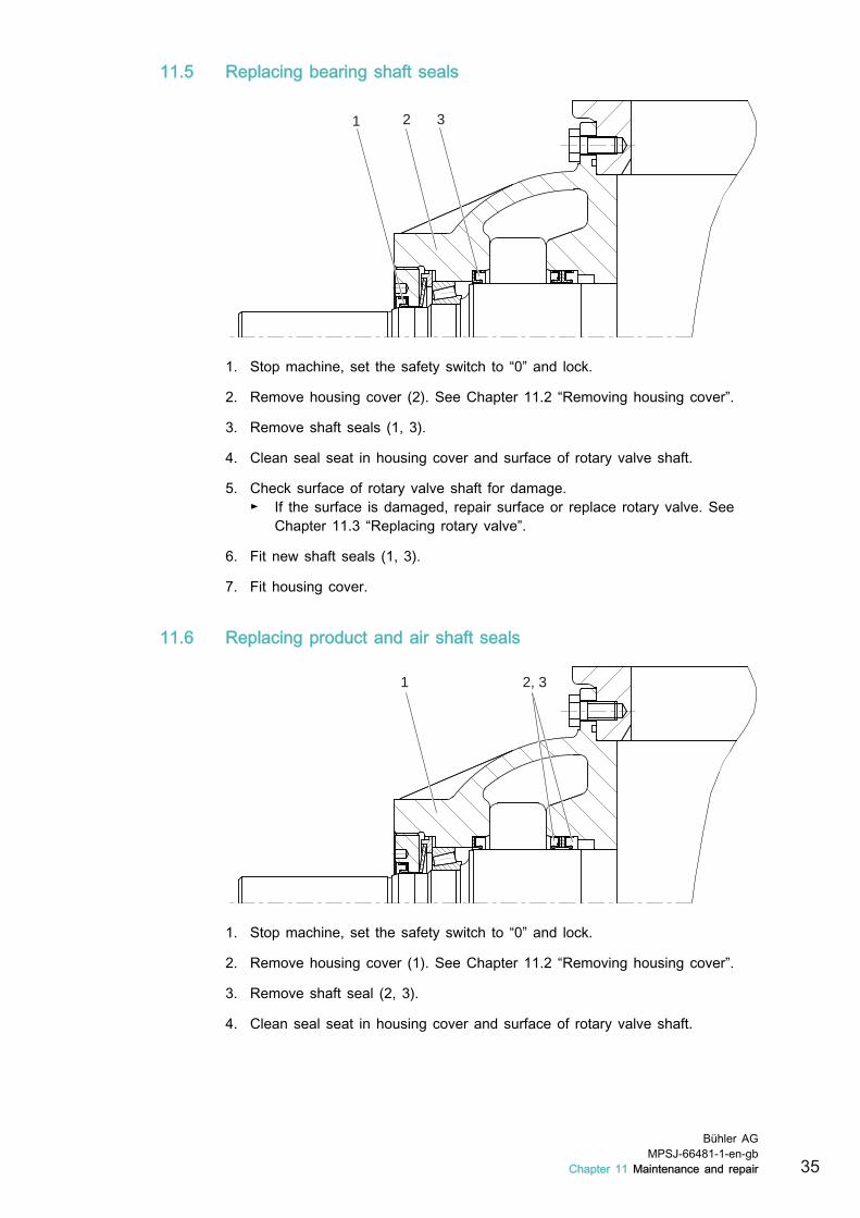
11.5 Replacing bearing shaft seals
31 2
1. Stop machine, set the safety switch to “0” and lock.
2. Remove housing cover (2). See Chapter 11.2 “Removing housing cover”.
3. Remove shaft seals (1, 3).
4. Clean seal seat in housing cover and surface of rotary valve shaft.
5. Check surface of rotary valve shaft for damage.► If the surface is damaged, repair surface or replace rotary valve. See
Chapter 11.3 “Replacing rotary valve”.
6. Fit new shaft seals (1, 3).
7. Fit housing cover.
11.6 Replacing product and air shaft seals
2, 31
1. Stop machine, set the safety switch to “0” and lock.
2. Remove housing cover (1). See Chapter 11.2 “Removing housing cover”.
3. Remove shaft seal (2, 3).
4. Clean seal seat in housing cover and surface of rotary valve shaft.
Bühler AGMPSJ-66481-1-en-gb
Chapter 11 Maintenance and repair 35
5. Check surface of rotary valve shaft for damage.► If the surface is damaged, repair surface (See Chapter 11.4 “Repairing
rotary valve shaft”.) or replace rotary valve. See Chapter 11.3 “Replacingrotary valve”.
6. Fit new shaft seals (2, 3).
7. Fit housing cover.
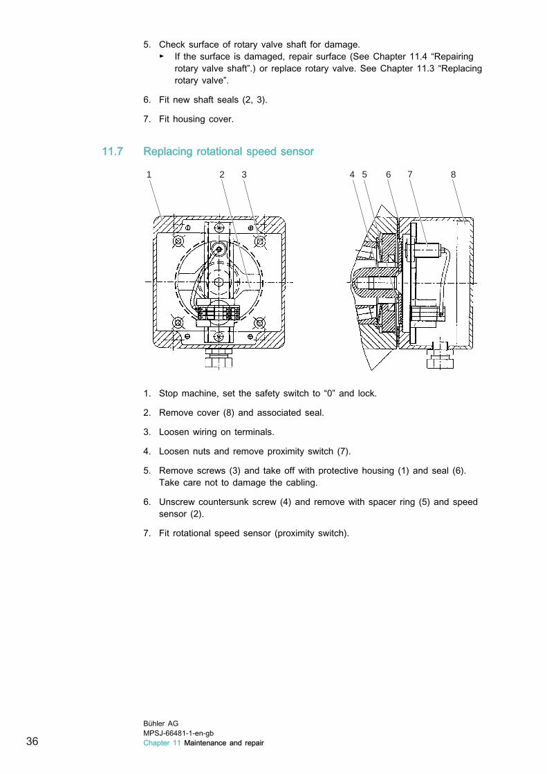
11.7 Replacing rotational speed sensor
1 72 3 4 5 6 8
1. Stop machine, set the safety switch to “0” and lock.
2. Remove cover (8) and associated seal.
3. Loosen wiring on terminals.
4. Loosen nuts and remove proximity switch (7).
5. Remove screws (3) and take off with protective housing (1) and seal (6).Take care not to damage the cabling.
6. Unscrew countersunk screw (4) and remove with spacer ring (5) and speedsensor (2).
7. Fit rotational speed sensor (proximity switch).
36Bühler AGMPSJ-66481-1-en-gbChapter 11 Maintenance and repair
12 Removal from Service
12.1 DismantlingAfter completing work with the machine (overhaul, removal or disposal), the ma-chine is dismantled in reverse order to the assembly.
► The responsible person must obtain instructions from the manufacturer forsafe dismantling before starting the dismantling work.
► The machine must only be dismantled in accordance with all accident pre-vention measures and only by instructed personnel. These personnel mustbe familiar with the safety precautions.
12.2 DisposalDispose of machine and component parts in accordance with the local applica-ble legal regulations.
► Sort metal parts according to type of metal and dispose of accordingly.
► Dispose of electric motors properly.
► Dispose of electronic parts properly.
► Dispose of plastic parts properly.
Bühler AGMPSJ-66481-1-en-gb
Chapter 12 Removal from Service 37

13 Spare parts
13.1 Spare parts stockA ready supply of spare parts and wearing parts plays an important role in en-suring the availability and correct operation of the machine.
Only use original spare parts listed in the spare parts catalogue. Parts obtainedfrom third-party suppliers may have an adverse effect on the operating behav-iour of the machine and can compromise its safety.
13.2 Ordering instructionsIncorrect parts may be shipped if the information in spare parts orders is incom-plete.
A spare parts order must contain the following information:
■ Machine number■ Component assembly number or part number■ Designation■ Quantity■ Motors: manufacturer and motor number■ Gearboxes: manufacturer and gearbox number
In case of any doubt, please enclose a dimensional drawing with a description.
13.3 Spare part identificationCode [C] DescriptionV Wear part
■ Parts which wear during normal operation.■ Parts which have to be replaced once or several times a year.
E Normal spare part■ Parts which in the event of their failure or defectiveness can
result in limited functionality of the machine.
38Bühler AGMPSJ-66481-1-en-gbChapter 13 Spare parts

13.4 Spare parts lists13.4.1 MPSJ-LP 18/15
Spare parts list no.: MPSJ-80000 open rotary valve
Spare parts list no.: MPSJ-80001 closed rotary valve
Item Parts no. Code Designation Quan-tity
23 OKEO-40006-01 E Adjustment cover
24 OKEO-40001-01 E Spacer ring
44 MPSJ-40006-01 E Seal ring 18/15 NBR
45 MPSJ-40006-08 E Seal ring FPM 75.5/VA75 for versions up to 140 °C andup to 220 °C
48 UXN-56014-032 E Tapered roller bearing 45/75x20
49 UNN-28002-744 E Spring wedge, shape A 8/7x63
50 UNN-48048-029 E Cup spring D41/80x2.25
51 UVN-44009-023 V Shaft seal NBR D72/90x10
52 UVN-44010-583 V Shaft seal PTFE D72/90x10 for versions up to 140 °Cand up to 220 °C
53 UNN-44009-019 V Shaft seal NBR D40/55x7
52 UVN-44010-565 V Shaft seal PTFE D40/55x8 for versions up to 140 °C andup to 220 °C
Bühler AGMPSJ-66481-1-en-gb
Chapter 13 Spare parts 39
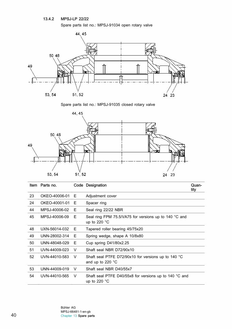
13.4.2 MPSJ-LP 22/22Spare parts list no.: MPSJ-91034 open rotary valve
Spare parts list no.: MPSJ-91035 closed rotary valve
Item Parts no. Code Designation Quan-tity
23 OKEO-40006-01 E Adjustment cover
24 OKEO-40001-01 E Spacer ring
44 MPSJ-40006-02 E Seal ring 22/22 NBR
45 MPSJ-40006-09 E Seal ring FPM 75.5/VA75 for versions up to 140 °C andup to 220 °C
48 UXN-56014-032 E Tapered roller bearing 45/75x20
49 UNN-28002-314 E Spring wedge, shape A 10/8x80
50 UNN-48048-029 E Cup spring D41/80x2.25
51 UVN-44009-023 V Shaft seal NBR D72/90x10
52 UVN-44010-583 V Shaft seal PTFE D72/90x10 for versions up to 140 °Cand up to 220 °C
53 UNN-44009-019 V Shaft seal NBR D40/55x7
54 UVN-44010-565 V Shaft seal PTFE D40/55x8 for versions up to 140 °C andup to 220 °C
40Bühler AGMPSJ-66481-1-en-gbChapter 13 Spare parts
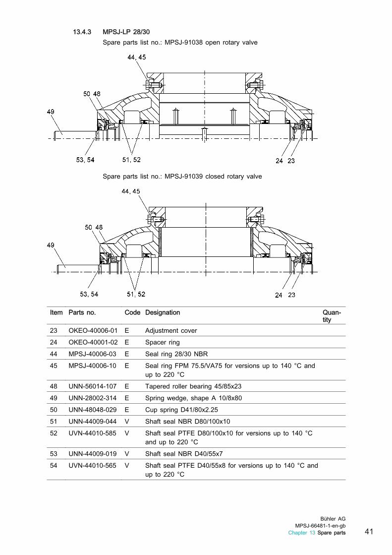
13.4.3 MPSJ-LP 28/30Spare parts list no.: MPSJ-91038 open rotary valve
Spare parts list no.: MPSJ-91039 closed rotary valve
Item Parts no. Code Designation Quan-tity
23 OKEO-40006-01 E Adjustment cover
24 OKEO-40001-02 E Spacer ring
44 MPSJ-40006-03 E Seal ring 28/30 NBR
45 MPSJ-40006-10 E Seal ring FPM 75.5/VA75 for versions up to 140 °C andup to 220 °C
48 UNN-56014-107 E Tapered roller bearing 45/85x23
49 UNN-28002-314 E Spring wedge, shape A 10/8x80
50 UNN-48048-029 E Cup spring D41/80x2.25
51 UNN-44009-044 V Shaft seal NBR D80/100x10
52 UVN-44010-585 V Shaft seal PTFE D80/100x10 for versions up to 140 °Cand up to 220 °C
53 UNN-44009-019 V Shaft seal NBR D40/55x7
54 UVN-44010-565 V Shaft seal PTFE D40/55x8 for versions up to 140 °C andup to 220 °C
Bühler AGMPSJ-66481-1-en-gb
Chapter 13 Spare parts 41

13.4.4 MPSJ-LP 36/38Spare parts list no.: MPSJ-91042 open rotary valve
Spare parts list no.: MPSJ-91043 closed rotary valve
Item Parts no. Code Designation Quan-tity
23 OKEO-40007-01 E Adjustment cover
24 OKEO-40001-03 E Spacer ring
44 MPSJ-40006-04 E Seal ring 36/38 NBR
45 MPSJ-40006-11 E Seal ring FPM 75.5/VA75 for versions up to 140 °C andup to 220 °C
48 UNN-56014-109 E Tapered roller bearing 55/100x25
49 UNN-28002-350 E Spring wedge, shape A 12/8x80
50 UNN-48048-046 E Cup spring D51/100x2.7
51 UNN-44009-053 V Shaft seal NBR D95/120x12
52 UVN-44010-589 V Shaft seal PTFE D95/120x12 for versions up to 140 °Cand up to 220 °C
53 UNN-44009-025 V Shaft seal NBR D50/68x8
54 UVN-44010-571 V Shaft seal PTFE D50/68x8 for versions up to 140 °C andup to 220 °C
42Bühler AGMPSJ-66481-1-en-gbChapter 13 Spare parts

13.4.5 MPSJ-LP 45/45Spare parts list no.: MPSJ-91046 open rotary valve
Spare parts list no.: MPSJ-91047 closed rotary valve
Item Parts no. Code Designation Quan-tity
23 OKEO-40007-01 E Adjustment cover
24 OKEO-40001-03 E Spacer ring
44 MPSJ-40006-05 E Seal ring 45/45 NBR
45 MPSJ-40006-12 E Seal ring FPM 75.5/VA75 for versions up to 140 °C andup to 220 °C
48 UNN-56014-109 E Tapered roller bearing 55/100x25
49 UNN-28002-350 E Spring wedge, shape A 12/8x80
50 UNN-48048-046 E Cup spring D51/100x2.7
51 UNN-44009-053 V Shaft seal NBR D95/120x12
52 UVN-44010-589 V Shaft seal PTFE D95/120x12 for versions up to 140 °Cand up to 220 °C
53 UNN-44009-025 V Shaft seal NBR D50/68x8
54 UVN-44010-571 V Shaft seal PTFE D50/68x8 for versions up to 140 °C andup to 220 °C
Bühler AGMPSJ-66481-1-en-gb
Chapter 13 Spare parts 43

13.4.6 MPSJ-LP 60/60Spare parts list no.: MPSJ-91054 open rotary valve
Spare parts list no.: MPSJ-91055 closed rotary valve
Item Parts no. Code Designation Quan-tity
23 OKEO-40008-01 E Adjustment cover
24 OKEO-40001-04 E Spacer ring
44 MPSJ-40006-07 E Seal ring 60/60 NBR
45 MPSJ-40006-14 E Seal ring FPM 75.5/VA75 for versions up to 140 °C andup to 220 °C
48 UNN-56014-114 E Tapered roller bearing 80/140x33
49 UNN-28002-386 E Spring wedge, shape A 14/9x80
50 UNN-48048-026 E Cup spring D72/140x3.8
51 UVN-44010-018 V Shaft seal NBR D135/160x15
52 UVN-44010-598 V Shaft seal PTFE D135/160x12 for versions up to 140 °Cand up to 220 °C
53 UNN-44009-038 V Shaft seal NBR D70/90x10
54 UVN-44010-581 V Shaft seal PTFE D70/90x10 for versions up to 140 °Cand up to 220 °C
44Bühler AGMPSJ-66481-1-en-gbChapter 13 Spare parts