Nonlinear vibrations of functionally graded cylindrical shells
Volume 4 • Issue 2 • 1000163J Appl Mech EngISSN:2168-9873 JAME, an open access journal
Open AccessResearch Article
Banerjee and Mazumdar, J Appl Mech Eng 2015, 4:2 DOI: 10.4172/2168-9873.1000163
Keywords: Iso-amplitude contour lines; Constant deflectioncontours; Shallow shells
IntroductionIn the linear theory of motion of elastic plates and shallow shells,
the strain of the middle surface can be neglected when the deflections are assumed to be small compared with the thickness of the surface. However, in most practical cases, this basic assumption is no longer valid; instead the deflections have the magnitude of the thickness of the surface. Hence the derivation of governing differential equations exhibiting large deflections needs special attention in such analyses.
The importance of the inclusion of nonlinear effects in problems relating to the strength and stability of modern flight structures has been made initially by von Kármán [1]. Indeed, the von Karman theory is widely used to account for the influence of large deflection in plates and shells. In fact, more than half a century ago it was Herrmann [2] who first proposed the nonlinear plate theory of motion corresponding to the dynamic analogue of the von Kármán theory.
It is well-known that the nonlinear dynamic behavior of thin shallow shell structures is of much technical importance to designers due to its wide range of applications in many fields of engineering. Containers, tanks, domes etc. are common examples of practical importance of such structures. However, the papers on nonlinear vibrations of shallow shell structures to date are limited in number.
The problems of nonlinear vibration of shallow shells have attracted the attention of relatively few investigators in the past [3-6]. Due to the very complicated nature of the basic equations governing the motion of a structure exhibiting large deflection, it has always been a difficult task for investigators to obtain even an approximate solution. Mazumdar in 1970 proposed a new approach which appeared to be quite suitable for bending analysis of elastic plates of arbitrary shapes based on the concept of iso-deflection contour lines on the bent surface of the plate [7]. This simple but efficient method is best known as Constant Deflection Contour Method or CDC-Method. Subsequently, the same method has been extended to the vibration analysis of plates and shallow shells [8,9].
The CDC method has so far been restricted to linear analysis until an attempt has been made recently to extend it to nonlinear analysis of plates [10,11]. In the present paper a similar approach as in [11] is undertaken for extension of the study to shallow shell analysis. This paper is therefore regarded as a sequel to earlier papers and deals with the nonlinear vibration of shallow shells based on the CDC Method. Some specific examples on nonlinear vibrations of shallow shells have
*Corresponding author: Banerjee MM, 202 Nandan Apartment, Hill view(N), Asansol-713304, West Bengal, India, Tel: +91-9434849434; E-mail:[email protected]
Received February 09, 2015; Accepted March 26, 2015; Published March 31, 2015
Citation: Banerjee MM, Mazumdar J (2015) On nonlinear vibration analysis of shallow shells – A new approach. J Appl Mech Eng 4: 163. doi:10.4172/2168-9873.1000163
Copyright: © 2015 Banerjee MM, et al. This is an open-access article distributed under the terms of the Creative Commons Attribution License, which permits unrestricted use, distribution, and reproduction in any medium, provided the original author and source are credited.
On nonlinear vibration analysis of shallow shells – A new approachBanerjee MM1* and Mazumdar J2
1202 Nandan Apartment, Hill view (N), Asansol-713304, West Bengal, India2School of Electrical and Electronic Engineering and School of Mathematical Sciences, the University of Adelaide, Australia
AbstractA method for the analysis of nonlinear vibration of shallow shells of arbitrary shape is presented. The method is
based upon the concept of constant deflection contours on the surface of the shallow shell. The constant deflection contour method has previously been found to be a simple tool for the study of linear vibration analysis of shallow shells of arbitrary shape. A new approach has been made here to utilize this concept to study the large amplitude vibration of shallow shells in conjunction with the Galerkin method. A number of illustrative examples are included to demonstrate the accuracy of the proposed method.
been included to show the efficacy of the method, and that the results are in excellent agreement with known results in the literature.
Derivation of Basic EquationsConsider an elastic, isotropic shallow shell of uniform thickness h
subject to a continuously distributed normal load q. Let the equation of the middle surface of the shell referred to a system of orthogonal coordinates xyz, be given by [9].
2 2
2 2x xy y
x xy yzR R R
= + + (2.1)
Where 2 2r x y= + is small compared to the least of the radii of curvature Rx, Ry, Rxy and (supposed to be constants).
If the shell is assumed to be comparatively thin and the displacements (u, v, w) are predominantly flexural, the strain components can be written as
22
2
1 ( )2
x yx
x
u w w wzx R x x E
σ νσε
−∂ ∂ ∂= + + − =∂ ∂ ∂
, 22
2
1 ( )2
y xy
y
v w w wzy R y y E
σ νσε
−∂ ∂ ∂= + + − =∂ ∂ ∂
( )22 2(1 )2xy xy
xy
v u w w w wzx y x y R x y E
νε σ∂ ∂ ∂ ∂ ∂ += + + + − =∂ ∂ ∂ ∂ ∂ ∂ (2.2)
With usual notations, the total strain energy is given by1 ( )2 x x y y xy xyU dzdxdyσ ε σ ε σ ε= + +∫∫∫ , (2.3)
Whereas the kinetic energy is
( )2 2 2( / 2)eT h u v w dxdyρ= + +∫∫
, (2.4)
And the work done is
kW pw dxdy=∫∫ (2.5)
Journal of Applied Mechanical EngineeringJo
urna
l of A
pplied Mechanical Engineering
ISSN: 2168-9873
Citation: Banerjee MM, Mazumdar J (2015) On nonlinear vibration analysis of shallow shells – A new approach. J Appl Mech Eng 4: 163. doi:10.4172/2168-9873.1000163
Page 2 of 8
Volume 4 • Issue 2 • 1000163J Appl Mech EngISSN:2168-9873, an open access journal
Formulating the Lagrangian with the help of the above expressions and applying Hamilton’s principle, a straightforward application of the variational calculus yield the following equations of motion [3]
4 , ,,( , ) 2 ,yy xyxx
ttx y xy
F FFD w hS F w h q hw
R R Rρ
∇ = − + − + −
(2.6)
and
4 , ,,( , ) 2
2yy xyxx
x y xy
w wwED F hS w w ER R R
∇ =− + + −
(2.7)
Where the operator S (w, F) stands for
2 2 2 2 2 2
2 2 2 2( , ) 2w F w F w FS w Fx y x y x y y x
∂ ∂ ∂ ∂ ∂ ∂≡ − +∂ ∂ ∂ ∂ ∂ ∂ ∂ ∂
Here ‘F’ denotes the Airy-Stress function, defined by
/2 /2 /22 2 2
2 2/2 /2 /2
, , ,h h h
xx x yy y xy xyh h h
F F Fdz N h dz N h dz N hy x x y
σ σ σ− − −
∂ ∂ ∂= = = = = =−
∂ ∂ ∂ ∂∫ ∫ ∫ (2.8a)
Whereas
/2 /2 /2
/2 /2 /2
, , , , , , (1 ) ,h h h
x x xx yy y yy xx xy xy xyh h h
M zdz D w w M zdz D w w M zdz D wσ ν σ ν σ ν− − −
= =− + = =− + = =− − ∫ ∫ ∫ (2.8b)
And the (,) notation signifies partial derivative with respect to the suffix.
A New Approach Mazumdar in [7] put forward a simple method, the so-called CDC-
Method to solve the static and dynamic problems of elastic plates of arbitrary shapes. Mazumdar et al [8,9,12-14] applied this method for solving various problems of elastic plates and shells of arbitrary shapes, restricted to linear cases only. Following Mazumdar [7], a new idea has been put forward by Banerjee [10] to study the dynamic response of structures of arbitrary shapes based on the CDC method. While Mazumdar utilized the concept of Deflection Contour method to deduce the basic dynamical equations using elementary theory of plates and shells [15-17], the authors in [11] found it easy to arrive at the final equations by straightforward utilization of von Kármán field equations and then utilizing the required transformations to u-variables. In most practical cases, it is found that von Kármán field equations in conjunction with the CDC-Method make it easy to apply for nonlinear analyses of plates and shells.
Theory and Derivation of Governing Equations When the plate or the shallow shell vibrates in a normal mode,
then at any instant θt , the intersections between the deflected surface and the parallels z=constant yield contours which after projection onto the base plane z=0 are a set of level curves, u(x,y)=constant, called the “Lines of Equal Deflections” [9], which are, in fact, iso-amplitude contour lines . The boundary of the plate or the shell irrespective of any combination of support is also a simple curve belonging to the family of lines of equal deflections.
As defined by Mazumdar [7] this family of nonintersecting curves may be denoted by uC , where *0 uu ≤≤ , so that 0C (u=0) is the boundary and *
uC coincides with the point(s) at which the maximum u=u* is attained.
Let u=u(x,y)=constant be a member of the family of iso-deflection or iso-amplitude contour lines.
Using the following transformations. 2
22
2
2
, ,
,
∂= = = +
∂
= = +
x x xx x xx
y y xy x y xy
w dw d w dww u w u ux du du du
dw d w dww u w u u udu du du
, etc. (4.1),
Equations (2.6) and (2.7) can be written as
[
tt
i
i
ii
whqdudF
duFdh
dudF
dudw
dudF
dudw
dudh
duwdD
,
]
82
2
7
655
54
1
ρλλ
λλλ
−+
+−
−+
=
−
−
=∑
(4.2)
2 254
9 1051
2
11 122
2
i
i ii
d F E d dw dwdu du du du
d w dwEdu du
λ λ λ
λ λ
−
−=
= − + +
+ +
∑ (4.3)
Where
( )2221 yx uu +=λ ( ) ( )2 2
2 6 2 6 2 8x xx yy y yy xx x y xyu u u u u u u u uλ = + + + +
( ) ( ) ( )2 2 23 3 4 4 4 2xx yy x xxx y yyy x xyy y xxy xy xx yyu u u u u u u u u u u u uλ = + + + + + + +
( ) ( )2 24 5 92 , 2xxxx xxyy yyyy x yy y xx x y xyu u u u u u u u u uλ λ λ= + + = + − =
( )2 2
26 10 7 112 2y x yx
xx yy xyx y xy
u u uuu u u
R R Rλ λ λ λ
= − = = + − =
7 122yy xyxx
x y xy
u uuR R R
λ λ
= + − =
(4.4)
Since Eqns. (4.2) and (4.3) are valid for all points on the surface of the shell, we can have
54
5 651
2
7 82
]
, 0
i
i ii
tt
d w d dw dF dw dFD hdu du du du du du
d F dFh q h w ddu du
λ λ λ
λ λ ρ
−
−=Ω
− +
+ + − + Ω =
∑∫∫ (4.5)
And
2 254
9 1051
2
11 122
( )2
0
i
i ii
d F E d dw dwdu du du du
d w dwE ddu du
λ λ λ
λ λ
−
−=Ω
+ + +
− + Ω =
∑∫∫ (4.6)
The integration is over the region bounded by any contour uC . While performing the above integrals it would be more convenient to utilize the formula in the modified form
2
1 2 32* 1
, , ,....., , ,... ( ) ( , )un
x xx nu
dw d w d w dsu u u d u x y dudu du du λΩ
Ψ Ω = − Ψ Ψ
∫∫ ∫ ∫ (4.7)
Which is a generalization of the formula adopted in Ref.[9]. Often it has been encountered that in the contour integral appearing in Eqn. (4.7), the integrand turns out to be dependent on u, and hence care should be taken to evaluate first the contour integral. Sometimes, it is useful to use the following relations for evaluation of the contour integral
2 21 2
4 , 2x yy x
ds dx dyu up p u u
λ = + = = = (4.8)
Citation: Banerjee MM, Mazumdar J (2015) On nonlinear vibration analysis of shallow shells – A new approach. J Appl Mech Eng 4: 163. doi:10.4172/2168-9873.1000163
Page 3 of 8
Volume 4 • Issue 2 • 1000163J Appl Mech EngISSN:2168-9873, an open access journal
Evaluation of the above integrals will yield two ordinary differential equations. Thus, in accordance with the present method, the basic fourth order partial differential equations reduce to ordinary differential equations which make it rather easy for further study.
Method of SolutionIt should be noted here that the above analysis is valid for any
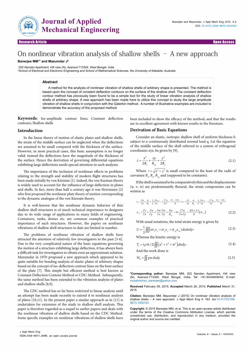
shallow shell structure. It has been already stated that equations (4.5) and (4.6) will yield two ordinary differential equations. For nonlinear analysis one may have to seek an approximate solution for which the form of the deflected function w must be first assumed compatible with the boundary conditions (Figure 1). Mathematically, this may be explained in the following way. Let u(x,y)=u denote a typical member of the family of the iso-deflection curves, then for any prescribed boundary conditions the deflection function w(u,t) can be assumed to take the form
w=A W (u) f (t) (5.1)
Where f(t) is an unknown function of time to be determined. Using this expression for the deflection function in the resultant equation of (4.6), we get the stress function in the form
, ( )F u f t=Φ (5.2)
With this expression for the stress function and previously assumed form of W, the resultant equation of (4.5) will yield, after using the Galerkin procedure, an ordinary time differential equation. Let us suppose that Eqn. (4.5) in combination with (5.1) and (5.2), yields the error function in the form
21 1 12, .. ( ), ( ) ( )u f t f t f tε λ λ = Λ
(5.3)
Because of the approximate nature of equation (5.1), the associated error function may be minimized using Galerkin method. The appropriate orthogonally condition applied to Eqn. (4.5) will yield the following “Time Differential Equation” with known constants in the form.
2 31 2 3( ) ( ) ( ) ( ) *F t F t F t f t qα α α+ + + = (5.4)
The solution of which can be obtained and from which the subsequent analysis can be performed.
Eqn. (5.4) can be studied for the following cases:
(a) Free linear vibration of Plates (when x yR and R → infinity) and shell (as the case may be)
(b) Free nonlinear vibration of plates and shells
(c) Static analysis of plates and shells.
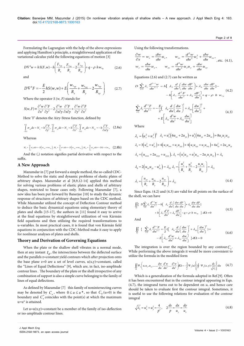
Specific IllustrationLarge vibration of a shallow dome upon an elliptical base
Consider the vibration of a shallow dome of nonzero Gaussian curvature upon an elliptic base. Figure 2 depicts the geometry of the shell. The edges are clamped and immovable. When the shell vibrates in a normal mode, the lines of equal deflections, as described in Sec.3, may reasonably be taken as
2 2
2 2( , ) 1 x yu x ya b
= − − (6.1)
Clearly, in this case u= 0 on the boundary and u=u*=1 at the center of the shell.
The corresponding values of are given by22 2 2 2 4 2 2 4
1 2 34 4 6 6 2 2
3 2 316 , 48 , 4x y x y a a b ba b a b a b
λ λ λ + +
= + = − + =
4 5 9 6 102 2 2 2
8(1 ) 80, ,ua b a b
λ λ λ λ λ−= = − = = =
2 2
7 11 8 124 4 2 2
1 14 , 2y x y x
x ya R b R a R b R
λ λ λ λ
= + = =− + =
(6.2)
Substituting the above values in Equations (4.5) and (4.6), and utilizing the formula given by (4.7) one gets
( ) ( ) ( )4 3 2
2
4 3 21 4 1 2 [(1 ) (1 )
(1 ) ,2 2 tt
d w d w d w d dw dFu u u udu du du du du du
hd dF qu wdu du DP DP
α
ρβ
− − − + = − − −
− − + −
(6.3)
( ) ( ) ( ) 4 3 2
2 2
4 3 21 4 1 2 [ (1 ) ]
(1 )
d F d F d F d dwu u udu du du du du
d dwudu du
γ
δ
− − − + = −
+ −
(6.4)
Where
2 2 2 2
4 2,hh E
DPa b DP Pa bκ
α β γ= = =
Figure 1: Iso-deflection curves.
Figure 2: Shallow dome placed on an elliptical base.
Citation: Banerjee MM, Mazumdar J (2015) On nonlinear vibration analysis of shallow shells – A new approach. J Appl Mech Eng 4: 163. doi:10.4172/2168-9873.1000163
Page 4 of 8
Volume 4 • Issue 2 • 1000163J Appl Mech EngISSN:2168-9873, an open access journal
4 2 2 4
4 4 2 2
3 2 3 1 1
y x
E a a b bPP a b a R b Rκ
δ κ + +
= = = +
(6.5)
It appears that the exact solutions of Eqns. (6.3) and (6.4) are not possible to find. So in order to obtain approximate solutions, let us assume
2( , ) ( ) ( ) ( )= ≈w u t W u f t Au f t (6.6)
Where f (t) is an unknown function of time to be determined.
Substitution of (6.6) in (6.4) the first integral of (6.4) yields
( ) 2 2 3 21
41 ( ) ( )3γ δ − = + +
d dFu A f t u A f t u Adu du
(6.7)
Which further integration reduces to
( ) 2 2 4 31 2
11 ( ) ( )3 3
dFu A f t u A f t u A u Adu
γ δ − = + + +
(6.8)
Considering the case for a clamped immovable edge condition we set the following conditions:
0
0u
dFdu =
= and 2
20
(1 ) 2(1 ) 0u
d F dFudu du
ν=
− − − =
(6.9)
Which make both A1 and A2 to be zero and Eqn. (6.8) reduces to
( ) 2 2 4 311 ( ) ( )3 3
dFu h f t u h f t udu
γ δ − = +
(6.10)
Substituting Equations (6.10) and (6.6) into Equations (6.3) and applying Galerkin procedure one gets after some mathematical operations
2 2 31 2 3 *h f f f f Qρ α α α+ + = (6.11)
Where
) 21 2
3
3
40 10 2 423 9 9
100 5, *21 3
DP DPA A
DP A qQ
α β δ α βγ δ α
γ αα
= + = +
= =
(6.12)
Where
2 2 2 2 2 2
4 1 1 2,y x
h h EDPa b DP a R b R Pa b
α β γ
= = + =
4 2 2 4
2 2 4 4
1 1 3 2 3
y x
E a a b bPP a R b R a b
δ + +
= + =
(6.13)
An indirect verification of the correctness of the time differential equation may be made by considering the case for a flat plate problem. When 0, 0,β δ→ → it implies
2 0α = and further if a=b the problem reduces to that of a circular plate for which Eqn. (6.11) takes the form (for )3.0=ν
42 3
4
59.756 4.762 ( )3
Ehh f f f q present studya
ρ + + =
42 3
4
59.768 4.6023
Ehh f f f qa
ρ + + =
(6.12)
0.0
0.5
1.0
1.5
2.0
2.5
0 10 20 30 40 50 60
Yamaki Present
(qa4/Eh4)w
max
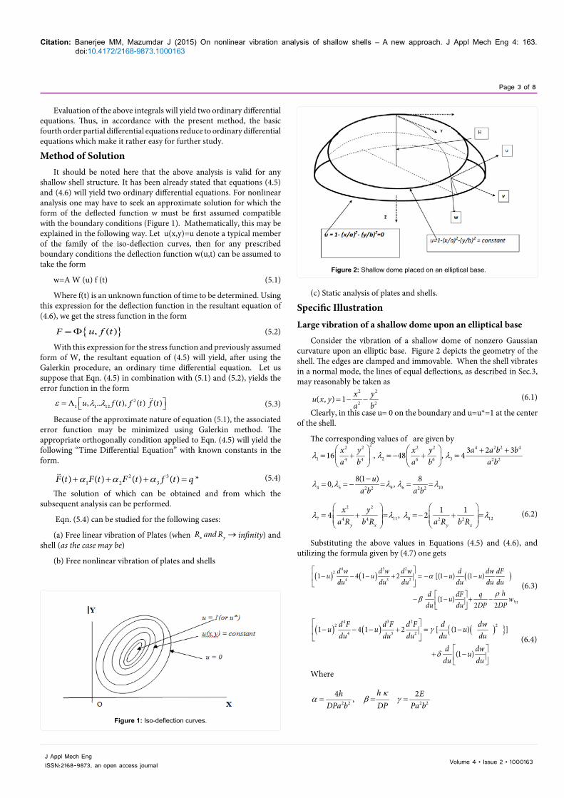
/ hFigure 3: Comparison of result with that of Yamaki [16].
0.0 0.5 1.0 1.5 2.0 2.5
0
400
800
1200
1600
2000
a/b=1v=0.3
γ ∗ = 0 γ ∗ = 1 γ ∗ = 3 γ ∗ = 5 γ ∗ = 10 γ ∗ = 15
(qa4 /E
h4 )
(wmax/h)
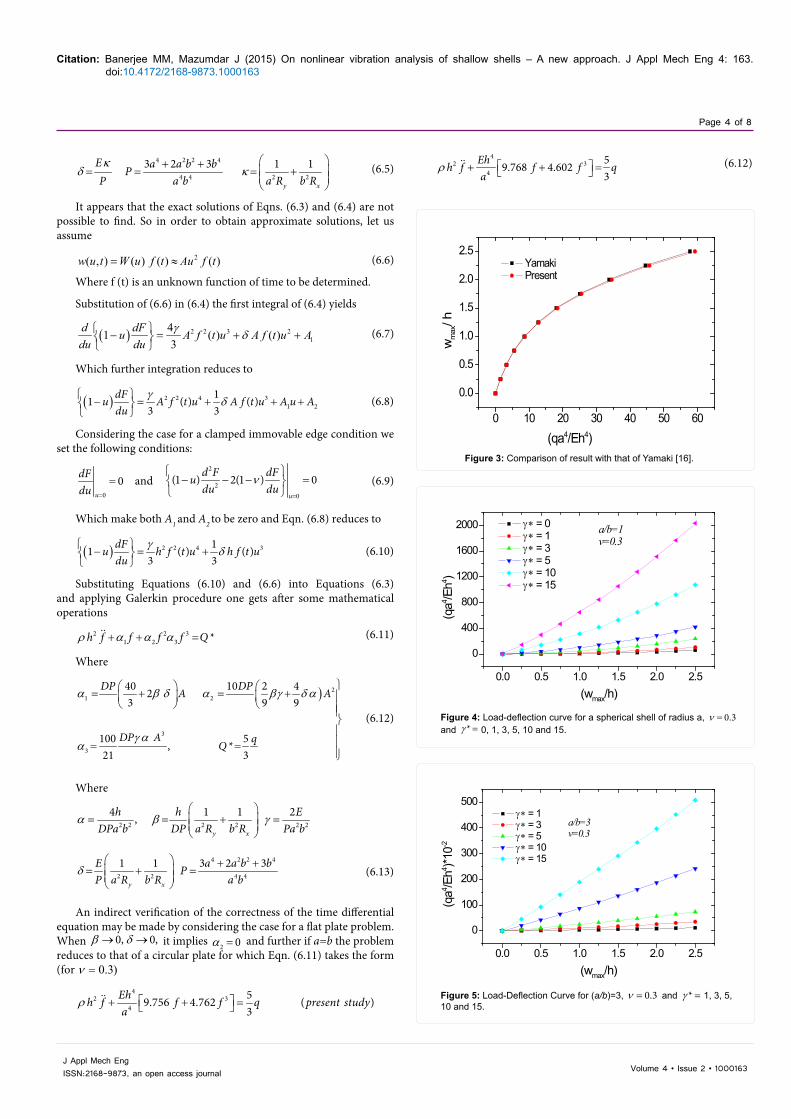
Figure 4: Load-deflection curve for a spherical shell of radius a, 0.3ν = and *γ = 0, 1, 3, 5, 10 and 15.
0.0 0.5 1.0 1.5 2.0 2.5
0
100
200
300
400
500
a/b=3v=0.3
γ ∗ = 1 γ ∗ = 3 γ ∗ = 5 γ ∗ = 10 γ ∗ = 15
(qa4 /E
h4 )*10-2
(wmax/h)
Figure 5: Load-Deflection Curve for (a/b)=3, 0.3ν = and *γ = 1, 3, 5, 10 and 15.
Citation: Banerjee MM, Mazumdar J (2015) On nonlinear vibration analysis of shallow shells – A new approach. J Appl Mech Eng 4: 163. doi:10.4172/2168-9873.1000163
Page 5 of 8
Volume 4 • Issue 2 • 1000163J Appl Mech EngISSN:2168-9873, an open access journal
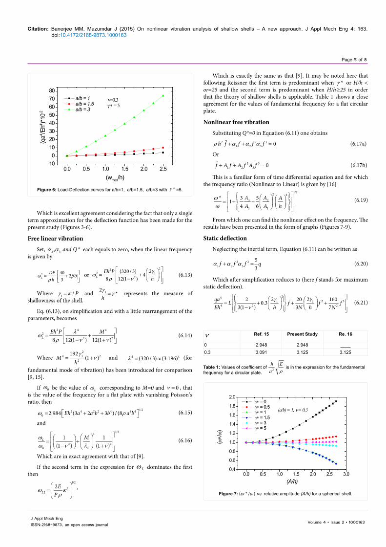
Which is excellent agreement considering the fact that only a single term approximation for the deflection function has been made for the present study (Figures 3-6).
Free linear vibration
Set, 2 3, *and Qα α each equals to zero, when the linear frequency is given by
2 40 23L
DPh
ω βδρ
= + or
222 1
2
2(320 / 3) 48 12(1 )L
Eh Phγ
ωρ ν
= + − (6.13)
Where 1 / Pγ κ= and 12 *hγ
γ= represents the measure of shallowness of the shell.
Eq. (6.13), on simplification and with a little rearrangement of the parameters, becomes
2 4 42
2 28 12(1 ) 12(1 )LEh P Mλωρ ν ν
= + − +
(6.14)
Where 214 2
2
192(1 )M
hγ
ν= + and 4 4(320 / 3) (3.196)λ = ≈ (for
fundamental mode of vibration) has been introduced for comparison [9, 15].
If 0ω be the value of Lω corresponding to M=0 and 0ν = , that is the value of the frequency for a flat plate with vanishing Poisson’s ratio, then
1/22 4 2 2 4 4 40 2.984 (3 2 3 ) / (8Eh a a b b a bω ρ = + + (6.15)
and1/24
2 20 0
1 1(1 ) (1 )
L Mωω ν λ ν
= + − + (6.16)
Which are in exact agreement with that of [9].
If the second term in the expression for Lω dominates the first then
1/2
22
2L
EP
ω κρ
=
,
Which is exactly the same as that [9]. It may be noted here that following Reissner the first term is predominant when *γ or H/h < or=25 and the second term is predominant when H/h≥25 in order that the theory of shallow shells is applicable. Table 1 shows a close agreement for the values of fundamental frequency for a flat circular plate.
Nonlinear free vibration
Substituting Q*=0 in Equation (6.11) one obtains2 2 3
1 2 3 0h f f f fρ α α α+ + = (6.17a)
Or2 3
1 2 3 0f A f A f A f+ + = (6.17b)
This is a familiar form of time differential equation and for which the frequency ratio (Nonlinear to Linear) is given by [16]
1/22 23 2
1 1
* 3 514 6
A A AA A h
ωω
= + −
(6.19)
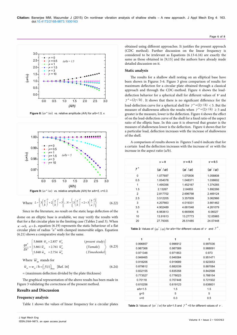
From which one can find the nonlinear effect on the frequency. The results have been presented in the form of graphs (Figures 7-9).
Static deflection
Neglecting the inertial term, Equation (6.11) can be written as
2 31 2 3
53
f f f qα α α+ = (6.20)
Which after simplification reduces to (here f stands for maximum static deflection).
242 31 1
4 2 2
2 22 20 1600.33(1 ) 3 7
qa L f f fEh h N h N
γ γν
= + + + − (6.21)
0.0 0.5 1.0 1.5 2.0 2.5-10
01020304050607080
γ ∗ = 5v=0.3 a/b = 1
a/b = 1.5 a/b = 3
(qa4 /E
h4 )*10-2
(wmax/h)
Figure 6: Load-Deflection curves for a/b=1, a/b=1.5, a/b=3 with *γ =5.
ν Ref. 15 Present Study Re. 16
0 2.948 2.948 ____0.3 3.091 3.125 3.125
Table 1: Values of coefficient of ρE
ah
2 is in the expression for the fundamental frequency for a circular plate.
0.0 0.5 1.0 1.5 2.0 2.5 3.00.4
0.6
0.8
1.0
1.2
1.4
1.6
1.8
2.0
(a/b) = 1, ν = 0.3
γ∗ = 0 γ∗ = 0.5 γ∗ = 1 γ∗ = 1.5 γ∗ = 3 γ∗ = 5
(ω∗/ω
)
(A/h)
Figure 7: ( * / )ω ω vs. relative amplitude (A/h) for a spherical shell.
Citation: Banerjee MM, Mazumdar J (2015) On nonlinear vibration analysis of shallow shells – A new approach. J Appl Mech Eng 4: 163. doi:10.4172/2168-9873.1000163
Page 6 of 8
Volume 4 • Issue 2 • 1000163J Appl Mech EngISSN:2168-9873, an open access journal
0.0 0.5 1.0 1.5 2.0 2.5 3.0
0.0
0.5
1.0
1.5
2.0
2.5
3.0
(a/b) = 1.5 γ∗ = 0 γ∗ = 0.5 γ∗ = 1 γ∗ = 1.5 γ∗ = 3 γ∗ = 10
(ω∗/ω
)
(A/h)
Figure 8: ( * / )ω ω vs. relative amplitude (A/h) for a/b=1.5, v.
0.0 0.5 1.0 1.5 2.0 2.5 3.0
0.97
0.98
0.99
1.00
(a/b) = 5
γ∗= 0 γ∗= 0.5 γ∗= 1 γ∗= 1.5 γ∗= 3 γ∗= 10
(ω∗/ω)
(A/h)Figure 9: ( * / )ω ω vs. relative amplitude (A/h) for a/b=5, v=0.3.
Where 4 2 2 2
3 2 3 , 3 2 3a a a bL Nb b b a
= + + = + +
(6.22)
Since in the literature, no result on the static large deflection of the
dome on an elliptic base is available, we may verify the results with that for a flat circular plate in the limiting case (Tables 2 and 3). When
0, a bκ → = , equation (6.19) represents the static behaviour of a flat circular plate of radius “a” with clamped immovable edges. Equation (6.21) shows a comparative study for the same.
( )
3
43
43
5.8608 2.857 ( )5.861 2.7615.848 2.754 (. )
m m
m m
m m
w w present studyqa w w YamakiEh
w w Timoshenko
+
= + +
(6.23)
Where mw stands for
max
/ ( )m mw w h f t= = [Ref. 16] (6.24)
= (maximum deflection divided by the plate thickness)
The graphical representation of the above results has been made in Figure 3 validating the correctness of the present method.
Results and DiscussionFrequency analysis
Table 1 shows the values of linear frequency for a circular plates
obtained using different approaches. It justifies the present approach (CDC method). Further discussion on the linear frequency is considered to be irrelevant as Equations (6.13-6.16) are exactly the same as those obtained in [9,15] and the authors have already made detailed discussion on it.
Static analysis
The results for a shallow shell resting on an elliptical base have been shown in Figures 3-6. Figure 3 gives comparison of results for maximum deflection for a circular plate obtained through a classical approach and through the CDC-method. Figure 4 shows the load-deflection behavior for a spherical shell for different values of ν and
* (2 / )hγ γ= . It shows that there is no significant difference for the load-deflection curve for a spherical shell for * (2 / )hγ γ= < 5. But the measure of shallowness affects the results when * (2 / )hγ γ= ≥ 5 and greater is the measure, lower is the deflection. Figure 4 shows the effect of on the load-deflection curve of the shell for a fixed ratio of the aspect ratio of the elliptic base. In this case it is observed that greater is the measure of shallowness lower is the deflection. Figure 4 shows that for a particular load, deflection increases with the increase of shallowness of the shell.
A comparison of results shown in Figures 5 and 6 indicate that for a certain load the deflection increases with the increase of or with the increase in the aspect ratio (a/b).
0ν = .0 3ν = .0 5ν =
*γ *( / )ω ω *( / )ω ω *( / )ω ω
0 1.077697 1.070936 1.0588080.5 1.054078 1.048371 1.0386021 1.495356 1.452167 1.374265
1.5 2.13267 2.04855 1.8922662 2.817702 2.696798 2.469124
2.5 3.512205 3.357009 3.0629663 4.207663 4.019331 3.661462
3.5 4.902489 4.681548 4.2610795 6.983613 6.665906 6.0602710 13.91613 13.27773 12.0596520 27.79355 26.51485 24.07448
Table 2: Values of *( / )ω ω for a/b=1for different values of ν and *γ .
1 1 10.996857 0.996912 0.9970360.987368 0.987589 0.9880910.971348 0.971853 0.9730.948465 0.949384 0.9514710.918206 0.919689 0.9230530.879812 0.882039 0.8870840.832155 0.835358 0.8425980.773527 0.778023 0.7881540.70118 0.707448 0.7215020.610256 0.619123 0.638831a/b=1.5 1.5 1.5
g=5 5 5v=0 0.3 0.5
Table 3: Values of *( / )ω ω for a/b=1.5 and *γ =5 for different values of ν .
Citation: Banerjee MM, Mazumdar J (2015) On nonlinear vibration analysis of shallow shells – A new approach. J Appl Mech Eng 4: 163. doi:10.4172/2168-9873.1000163
Page 7 of 8
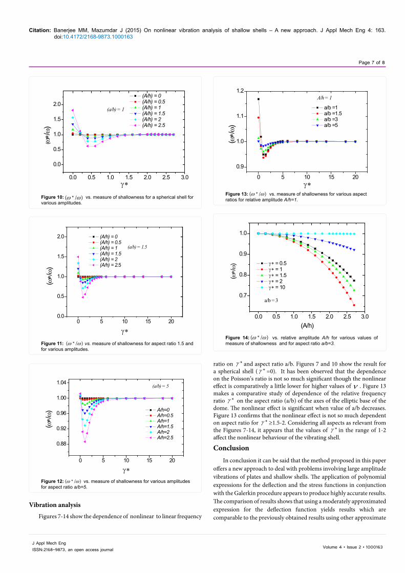
Volume 4 • Issue 2 • 1000163J Appl Mech EngISSN:2168-9873, an open access journal
Vibration analysis
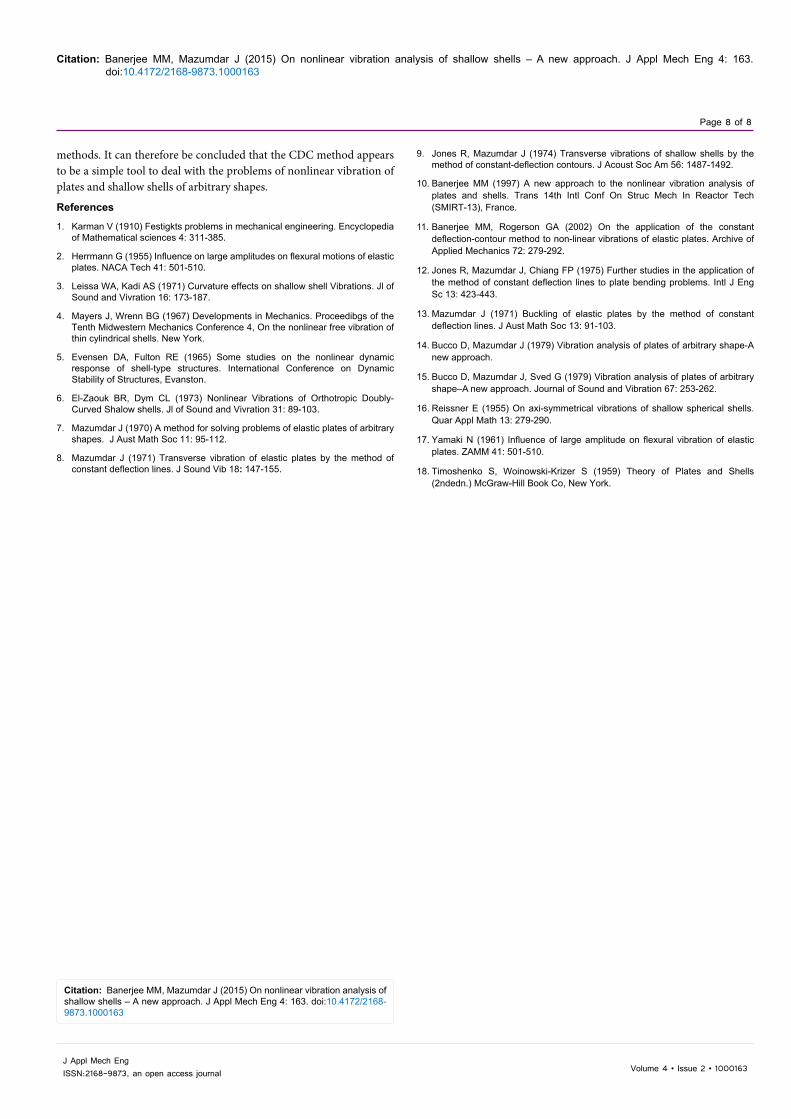
Figures 7-14 show the dependence of nonlinear to linear frequency
ratio on *γ and aspect ratio a/b. Figures 7 and 10 show the result for a spherical shell ( *γ =0). It has been observed that the dependence on the Poisson’s ratio is not so much significant though the nonlinear effect is comparatively a little lower for higher values of ν . Figure 13 makes a comparative study of dependence of the relative frequency ratio *γ on the aspect ratio (a/b) of the axes of the elliptic base of the dome. The nonlinear effect is significant when value of a/b decreases. Figure 13 confirms that the nonlinear effect is not so much dependent on aspect ratio for *γ ≥1.5-2. Considering all aspects as relevant from the Figures 7-14, it appears that the values of *γ in the range of 1-2 affect the nonlinear behaviour of the vibrating shell.
ConclusionIn conclusion it can be said that the method proposed in this paper
offers a new approach to deal with problems involving large amplitude vibrations of plates and shallow shells. The application of polynomial expressions for the deflection and the stress functions in conjunction with the Galerkin procedure appears to produce highly accurate results. The comparison of results shows that using a moderately approximated expression for the deflection function yields results which are comparable to the previously obtained results using other approximate
0.0 0.5 1.0 1.5 2.0 2.5 3.0
0.0
0.5
1.0
1.5
2.0
(a/b) = 1
(A/h) = 0 (A/h) = 0.5 (A/h) = 1 (A/h) = 1.5 (A/h) = 2 (A/h) = 2.5
( ω∗/ω
)
γ ∗
Figure 10: ( * / )ω ω vs. measure of shallowness for a spherical shell for various amplitudes.
0 5 10 15 200.0
0.5
1.0
1.5
2.0
(a/b) = 1.5
(A/h) = 0 (A/h) = 0.5 (A/h) = 1 (A/h) = 1.5 (A/h) = 2 (A/h) = 2.5
(ω∗/
ω)
γ ∗
Figure 11: ( * / )ω ω vs. measure of shallowness for aspect ratio 1.5 and for various amplitudes.
0 5 10 15 20
0.88
0.92
0.96
1.00
1.04
(a/b) = 5
A/h=0 A/h=0.5 A/h=1 A/h=1.5 A/h=2 A/h=2.5
(ω∗/ω
)
γ ∗Figure 12: ( * / )ω ω vs. measure of shallowness for various amplitudes for aspect ratio a/b=5.
0 5 10 15 20
0.9
1.0
1.1
1.2
A/h = 1
a/b =1 a/b =1.5 a/b =3 a/b =5
(ω∗/ω
)
γ ∗Figure 13: ( * / )ω ω vs. measure of shallowness for various aspect ratios for relative amplitude A/h=1.
0.0 0.5 1.0 1.5 2.0 2.5 3.0
0.7
0.8
0.9
1.0
a/b = 3
γ ∗ = 0.5 γ ∗ = 1 γ ∗ = 1.5 γ ∗ = 2 γ ∗ = 10
(ω∗/ω
)
(A/h)
Figure 14: ( * / )ω ω vs. relative amplitude A/h for various values of measure of shallowness and for aspect ratio a/b=3.
Citation: Banerjee MM, Mazumdar J (2015) On nonlinear vibration analysis of shallow shells – A new approach. J Appl Mech Eng 4: 163. doi:10.4172/2168-9873.1000163
Page 8 of 8
Volume 4 • Issue 2 • 1000163J Appl Mech EngISSN:2168-9873, an open access journal
methods. It can therefore be concluded that the CDC method appears to be a simple tool to deal with the problems of nonlinear vibration of plates and shallow shells of arbitrary shapes.
References
1. Karman V (1910) Festigkts problems in mechanical engineering. Encyclopedia of Mathematical sciences 4: 311-385.
2. Herrmann G (1955) Influence on large amplitudes on flexural motions of elastic plates. NACA Tech 41: 501-510.
3. Leissa WA, Kadi AS (1971) Curvature effects on shallow shell Vibrations. Jl ofSound and Vivration 16: 173-187.
4. Mayers J, Wrenn BG (1967) Developments in Mechanics. Proceedibgs of theTenth Midwestern Mechanics Conference 4, On the nonlinear free vibration ofthin cylindrical shells. New York.
5. Evensen DA, Fulton RE (1965) Some studies on the nonlinear dynamicresponse of shell-type structures. International Conference on DynamicStability of Structures, Evanston.
6. El-Zaouk BR, Dym CL (1973) Nonlinear Vibrations of Orthotropic Doubly-Curved Shalow shells. Jl of Sound and Vivration 31: 89-103.
7. Mazumdar J (1970) A method for solving problems of elastic plates of arbitrary shapes. J Aust Math Soc 11: 95-112.
8. Mazumdar J (1971) Transverse vibration of elastic plates by the method ofconstant deflection lines. J Sound Vib 18: 147-155.
9. Jones R, Mazumdar J (1974) Transverse vibrations of shallow shells by themethod of constant-deflection contours. J Acoust Soc Am 56: 1487-1492.
10. Banerjee MM (1997) A new approach to the nonlinear vibration analysis ofplates and shells. Trans 14th Intl Conf On Struc Mech In Reactor Tech(SMIRT-13), France.
11. Banerjee MM, Rogerson GA (2002) On the application of the constantdeflection-contour method to non-linear vibrations of elastic plates. Archive of Applied Mechanics 72: 279-292.
12. Jones R, Mazumdar J, Chiang FP (1975) Further studies in the application ofthe method of constant deflection lines to plate bending problems. Intl J Eng Sc 13: 423-443.
13. Mazumdar J (1971) Buckling of elastic plates by the method of constantdeflection lines. J Aust Math Soc 13: 91-103.
14. Bucco D, Mazumdar J (1979) Vibration analysis of plates of arbitrary shape-Anew approach.
15. Bucco D, Mazumdar J, Sved G (1979) Vibration analysis of plates of arbitraryshape–A new approach. Journal of Sound and Vibration 67: 253-262.
16. Reissner E (1955) On axi-symmetrical vibrations of shallow spherical shells.Quar Appl Math 13: 279-290.
17. Yamaki N (1961) Influence of large amplitude on flexural vibration of elastic plates. ZAMM 41: 501-510.
18. Timoshenko S, Woinowski-Krizer S (1959) Theory of Plates and Shells (2ndedn.) McGraw-Hill Book Co, New York.
Citation: Banerjee MM, Mazumdar J (2015) On nonlinear vibration analysis of shallow shells – A new approach. J Appl Mech Eng 4: 163. doi:10.4172/2168-9873.1000163