on any project where moisture-sensitive floor coverings RH … · 2019-10-03 · 11 12 The ASTM...
9
Transcript of on any project where moisture-sensitive floor coverings RH … · 2019-10-03 · 11 12 The ASTM...

2
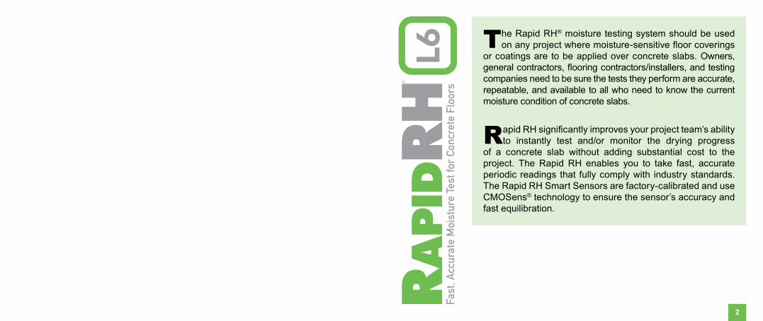
The Rapid RH® moisture testing system should be used on any project where moisture-sensitive floor coverings
or coatings are to be applied over concrete slabs. Owners, general contractors, flooring contractors/installers, and testing companies need to be sure the tests they perform are accurate, repeatable, and available to all who need to know the current moisture condition of concrete slabs.
Rapid RH significantly improves your project team’s ability to instantly test and/or monitor the drying progress
of a concrete slab without adding substantial cost to the project. The Rapid RH enables you to take fast, accurate periodic readings that fully comply with industry standards. The Rapid RH Smart Sensors are factory-calibrated and use CMOSens® technology to ensure the sensor’s accuracy and fast equilibration.

3 4
Correct hole depth and hole diameter are important in complying with the ASTM F2170 standard. For easy installation of a Rapid RH L6 Smart Sensor, a uniformly round hole is also important. Drill a hole in the concrete slab to the required depth using a rotary hammer drill and a ¾”-diameter masonry drill bit. Per the ASTM F2170 standard, drill the hole to a depth equaling 40% of the slab’s thickness for slabs that are drying from one side, or 20% depth for a slab drying from two sides. For proper Rapid RH L6 installation, be sure to position the drill perpendicular (90˚) to the surface being tested.
TIP: If you do not have a depth gauge for your drill, mark or tape-off your drill bit to the correct depth setting.
Step 1: Drill the HoleAttach the vacuum attachment to the straight extension of a shop vacuum cleaner hose* and thoroughly vacuum up the dust in and around the hole.
Next, insert the wire bristle brush into the hole. Turn the brush several times to loosen pulverized concrete from the walls of the hole. Vacuum again. Repeat this step twice to ensure no loose concrete particles remain in the hole.
IMPORTANT: Correct Diameter and Hole Uniformity: Use the ¾”-diameter section of the insertion tool as a diameter and uniformity gauge to ensure a correct and uniformly round hole. If the ¾”-diameter section of the tool will not go easily into the hole, the drill bit may be out-of-spec (worn out, etc.) or the hole may not have a uniform diameter from top to bottom. Not performing this step may cause damage to the L6 Smart Sensor when attempting insertion.
Step 2: Clean the Hole
*The vacuum attachment may require an adapter depending on vacuum model.
Vacuum Brush Clean 3/4” Diameter SectionDrill

5 6
TIP: Check the L6 Smart Sensor prior to installation to ensure there is a properly functioning sensor that is giving a reading.
Directly out of the package, the L6 Smart Sensor is 1.6” in length or 40% of a 4” thick slab. ASTM F2170, Section 10.2 states: “Slab drying from top only (example: slab on ground with vapor retarder below, or slab on metal deck): 40% depth. Slab drying from top and bottom (example: elevated structural slab not in metal deck): 20% depth).” Each Smart Sensor pack includes a number of short (0.4”) extensions that can be inserted into the L6 Smart Sensor barrel to enable use in thicker slabs. Adding one insert extends the Smart Sensor barrel length to 2” for testing 5”-thick slabs to the 40% depth. Keep any unused extensions for future jobs. If needed, you can use additional extensions to increase the length of the sensor barrel for thicker slab applications.
In summary, add one extension insert to an L6 Smart Sensor barrel for every 1” increase in slab thickness over 4” to meet the 40% depth requirement. The extension inserts make the Smart Sensor’s usage flexible for varying thicknesses of concrete.
Now, for all installations, take the L6 Smart Sensor directly out
Step 3: Insert the L6 Smart Sensor
Insert Smart Sensor Using Insertion Tool
of the package, and with no extensions installed, insert the L6 Smart Sensor into the hole using the insertion tool. Push down on the insertion tool until the L6 Smart Sensor is seated firmly at the bottom of the hole (review the IMPORTANT hole diameter and uniformity comment under Step 2). Under no circumstances should you tap or hammer the insertion tool to attempt to insert the sensor. Doing so may cause damage to the L6 Smart Sensor and will void any warranty. At this point, remove the protective liner covering the butyl tape from the underside of the protective cap, place the cap and extension(s), if necessary, onto the base sleeve, and push down to the concrete surface. This last step completes the installation process.
Remember: Correct depth of hole is critical to adhere to the ASTM F2170 standard.
Caution: NEVER use your Total Reader® device to install the L6 Smart Sensor.
Attach Extensions as Appropriate for Concrete
Slab Depth

7 8
When ready to take readings, remove the green rubber plug from the center of the protective cap from the Smart Sensor, and ensure no dust or debris is inside. Insert the Rapid RH L6 Total Reader firmly until it comes fully into contact with the bottom of the Smart Sensor. Hold the Total Reader in place until the first relative humidity reading appears on the screen, then immediately remove the Total Reader. The display will toggle back and forth between the relative humidity value (when the cursor is next to the %RH symbol) and the temperature value (when the cursor is next to the °F or °C symbol). Once the Total Reader is removed from the L6 Smart Sensor, the readings from that L6 Smart Sensor will continue to display for approximately 1 minute or until the Total Reader is reinserted into another Smart Sensor. After removal, wait at least 5 seconds before inserting the Total Reader into another Smart Sensor. Replace the Total Reader’s plastic end caps when not in use.
In most cases, one hour after installation, the L6 Smart Sensor will generally give a reading within 3-5% RH of the reading you would see after the ASTM-required 24-hour mark. Just remember to follow the ASTM F2170 procedures pertaining to equilibration time.
Step 4: Take ReadingsTotal Reader
Inserted into a Smart Sensor
After the initial equilibration has been reached per ASTM F2170 requirements, subsequent readings can be taken instantly. If future testing is needed, replace the protective plug by pushing it back into the protective cap.
Record readings on the enclosed report form in the spaces provided for information required by ASTM F2170, including the date, time, %RH and temperature. The grid at the bottom of the report form can be used to record test-hole locations. Each L6 Smart Sensor is serialized on the outside of the sensor barrel.
Extra copies of the report form and an ASTM F2170 checklist can be downloaded at www.rapidrh.com. You can also visit www.rhspec.com to visit links to various finished flooring manufacturers’ installation guides and their RH thresholds. For any additional questions related to what RH levels are appropriate, please contact the manufacturer of the product to be applied to the concrete slab.
Record readings on report form included with Smart Sensors

9 10
If future readings are no longer needed (for example, when ready to apply a floor covering or coating), remove the plastic cap and place the stainless steel metal disk over the Smart Sensor and skim-coat the hole with a cementitious patching compound compatible with the flooring manufacturer’s installation instructions. The metal disk will help you find the hole with a metal detector if you need to take additional readings, download previous readings, or simply provide evidence that you’ve conducted the test.
Step 5: Encapsulate Smart SensorPlace Metal Disk over Smart Sensor before Encapsulating
Apply Cementitious Patching Compound
Total Reader LCD display shows “ER”: The Rapid RH Total Reader may not be properly communicating with the L6 Smart Sensor for the following reasons:
1. The Total Reader was not in contact with the L6 Smart Sensor long enough. Hold the Total Reader in the L6 Smart Sensor until the first relative humidity reading appears on the screen, then remove.
2. Debris is blocking proper contact. Check the L6 Smart Sensor housing for any debris.
Replace the battery: The Total Reader will read “LO” when the battery is running low. The Total Reader comes with one CR1/3N battery. To replace the battery, open up the battery cover by removing the one battery cover screw with a jeweler’s Phillips screwdriver. DO NOT OPEN UP THE FULL BODY OF THE TOTAL READER AT ANY TIME.
Time-stamped readings: The Total Reader uses an internal clock to store time-stamped measurements. It will sync with your smartphone’s clock when linked to the DataMaster™ L6 app to give you readings stamped with your local time. With the DataMaster L6 app open, touch the Total Reader to an L6 Smart Sensor for 5 seconds or more to sync with your local time. Sync your Total Reader periodically to ensure your readings are recorded with the precise time-stamp.
Troubleshooting
11 12
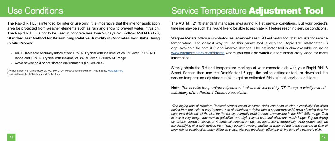
The ASTM F2170 standard mandates measuring RH at service conditions. But your project’s timeline may be such that you’d like to be able to estimate RH before reaching service conditions.
Wagner Meters offers a simple-to-use, science-based RH estimator tool that adjusts for service temperature. The easiest way to use this handy tool is with the Rapid RH DataMaster L6 app, available for both iOS and Android devices. The estimator tool is also available online at www.wagnermeters.com/rhtemp where you can also watch a short introductory video for more information.
Simply obtain the RH and temperature readings of your concrete slab with your Rapid RH L6 Smart Sensor, then use the DataMaster L6 app, the online estimator tool, or download the service temperature adjustment table to get an estimated RH value at service conditions.
Note: The service temperature adjustment tool was developed by CTLGroup, a wholly-owned subsidiary of the Portland Cement Association.
*The drying rate of standard Portland cement-based concrete slabs has been studied extensively. For slabs drying from one side, a very ‘general’ rule-of-thumb as a drying rate is approximately 30 days of drying time for each inch thickness of the slab for the relative humidity level to reach somewhere in the 85%-90% range. This is only a very rough approximate guideline, and drying times can, and often are, much longer if good drying conditions (closed-in space, environmental controls on, etc) are not present. Additionally, other factors such as the densifying of a slab surface from heavy power-troweling, additional water added to the concrete at time of pour, rain or construction water sitting on a slab, etc, can drastically affect the drying time of a concrete slab.
Service Temperature Adjustment ToolThe Rapid RH L6 is intended for interior use only. It is imperative that the interior application area be protected from weather elements such as rain and snow to prevent water intrusion. The Rapid RH L6 is not to be used in concrete less than 28 days old. Follow ASTM F2170, Standard Test Method for Determining Relative Humidity in Concrete Floor Slabs Using in situ Probes1.
• NIST2 Traceable Accuracy Information: 1.5% RH typical with maximal of 2% RH over 0-90% RH range and 1.8% RH typical with maximal of 3% RH over 90-100% RH range.
• Avoid severe cold or hot storage environments (i.e. vehicles). 1Available from ASTM International, P.O. Box C700, West Conshohocken, PA 19428-2959, www.astm.org2National Institute of Standards and Technology
Use Conditions

Wagner Meters warrants the Rapid RH L6 Smart Sensor and Rapid RH Total Reader products against defects in material and workmanship for one (1) year from the date of purchase, subject to the following terms and conditions:
Wagner Meters’ liability under this warranty shall be limited, at Wagner Meters’ option, to the repair or replacement of products or any part thereof, which are demonstrated to be defective. To exercise this warranty, customer must send product back with a copy of the proof of purchase date, the reason for return and, if Wagner determines it is under warranty, Wagner will replace the customer’s product. This limited warranty does not apply if the product has been damaged by accident, negligent handling, misuse, alteration, damage during shipment, or improper service. Wagner Meters shall in no event be liable for any breach of warranty or defect in this product, which exceeds the amount of purchase price of the product.
Relative humidity is one of many factors necessary for construction decisions. Wagner Meters does not assume responsibility for any particular construction decision based on the readings of this instrument and does not guarantee any specific construction results.
The method of use of this instrument and the interpretation of the readings are beyond the control of the manufacturer. Wagner Meters cannot accept responsibility for any loss, consequential or otherwise, resulting from the use of the Rapid RH L6 and its accessories.
All Rapid RH L6 Smart Sensor packs should come with a NIST traceable certificate of calibration that has a calibration assurance date to ensure ASTM F2170 compliance. If the Total Reader does not appear to function properly for any reason, contact Wagner Meters for remedy.
This warranty is in lieu of all other warranties, whether oral or written, express or implied. Any implied warranties, including implied warranties of merchantability and fitness for a particular purpose, are excluded. If this product is not in good working order as warranted above, the customer’s sole remedy shall be repair or replacement as provided above.
This warranty is personal to the customer purchasing the product from Wagner Meters or from its authorized distributors and is not transferable.
The agents and employees of Wagner Meters are not authorized to make modifications of this warranty or additional warranties binding on Wagner Meters. Accordingly, additional statements, whether oral or written, except written statements from an officer of Wagner Meters, do not constitute warranties and should not be relied upon by the customer.
Wagner Meters Limited Warranty Notes
13

For more information on relative humidity testing and to order online go to
www.RapidRH.com
500-R0000-006 REV A
©Wagner Meters 2019
All rights reserved. No part of this publication may be reproduced, stored in a retrieval system, or transmitted, in any form or by any means, electronic, mechanical, photocopying, recording, or otherwise, without the prior written permission of the publisher. The information in this document is subject to change without notice.
Wagner Meters326 Pine Grove Road
Rogue River, OR 97537Worldwide Toll-Free: (844) 296-9656
The RAPID RH®
L6 is registered under U.S. Patent 7231815, 8047056 & 9032791.


![Window Coverings[1]](https://static.fdocuments.in/doc/165x107/54168ab28d7f722f6c8b4b03/window-coverings1.jpg)