O&K Gearboxes
21
Technical Data
description
Planetary gearboxes, winch drives replacement for Bonfiglili gearboxes.
Transcript of O&K Gearboxes
TechnicalData
2 3
D3
D2
D1
L6L5L4
L9L8
L7
L3L2
L1R2R1
D6
D5
D4
D9
D8
D7
TRAVEL DRIVESTRAVEL DRIVES
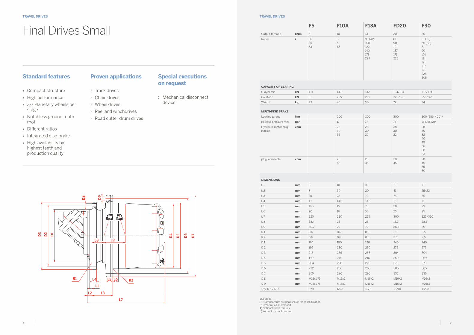
Final Drives Small
1) 2-stage 2) Stated torques are peak values for short duration3) Other ratios on demand 4) Optional brake torques 5) Without Hydraulic motor
Standard features
› Compact structure
› High performance
› 3-7 Planetary wheels per stage
› Notchless ground tooth root
› Different ratios
› Integrated disc-brake
› High availability by highest teeth and production quality
Proven applications
› Track drives
› Chain drives
› Wheel drives
› Reel and winchdrives
› Road cutter drum drives
Special executions on request
› Mechanical disconnect device
F5 F10A F13A FD20 F30
Output torque 2 kNm 5 10 13 20 30
Ratio 3 i 303553
355165
93 (41) 1
108122140178229
8190101137171228
61 (19) 1
66 (32) 1
8190101114121137171228305
CAPACITy oF bEARINg
C-dynamic kN 194 132 132 194/194 132/194
Co-static kN 315 255 255 325/315 255/325
Weigh 5 kg 43 45 50 72 94
MuLTI-DISk bRAkE
Locking torque Nm 200 200 300 300 (255; 400) 4
Release pressure min. bar 17 17 16 16 (16; 22) 4
Hydraulic motor plug in fixed
ccm 283032
283032
283032
2830324045566063
plug in variable ccm 2845
2845
2845
284555 60
DIMENSIoNS
L 1 mm 8 10 10 10 13
L 2 mm 8 30 30 41 25/22
L 3 mm 70 72 72 75 75
L 4 mm 19 13.5 13.5 15 15
L 5 mm 18.5 15 15 28 29
L 6 mm 20 16 16 25 25
L 7 mm 220 230 255 300 323/320
L 8 mm 38.4 28 28 15.3 28.5
L 9 mm 80.2 79 79 86.3 89
R 1 mm 0.6 0.6 0.6 2.5 2.5
R 2 mm 0.6 0.6 0.6 2.5 2.5
D 1 mm 165 190 190 240 240
D 2 mm 192 230 230 275 275
D 3 mm 215 256 256 304 304
D 4 mm 190 216 216 250 269
D 5 mm 204 220 220 270 270
D 6 mm 232 260 260 305 305
D 7 mm 255 290 290 335 335
D 8 mm M12x1.75 M16x2 M16x2 M16x2 M16x2
D 9 mm M12x1.75 M16x2 M16x2 M16x2 M16x2
Qty. D 8 / D 9 9/9 12/8 12/8 18/18 18/18

4 5
D3
D2
D1
L6L5L4
L9L8
L7
L3L2
L1R2R1
D6
D5
D4
D9
D8
D7
TRAVEL DRIVESTRAVEL DRIVES
Standard features
› Compact structure
› High performance
› 3-7 Planetary wheels per stage
› Notchless ground tooth root
› Different ratios
› Integrated disc-brake
› High availability by highest teeth and production quality
Proven applications
› Track drives
› Chain drives
› Wheel drives
› Reel and winchdrives
› Road cutter drum drives
Special executions on request
› Mechanical disconnect device
Final Drives MediumF40 F40A F40Xb F55 F55A F55b F55Xb
Output torque 2 kNm 40 40 40 55 55 55 55
Ratio 3 i 61 (19) 1
66 (22) 1
81 (32) 1
85101 110 117 124 142 181
61 (19) 1
66 (22) 1
81 (32) 1
85101 110 117 124 142 181
61 (19) 1
66 (22) 1
81 (26) 1
85 (32) 1
101110117124142181
63 (16) 1 68 (19) 1 87 (22) 1 94 (32) 1 103117124 137 148 185
63 (16) 1 68 (19) 1 87 (22) 1 94 (32) 1 103117124 137 148 185
63 (16) 1 68 (19) 1 87 (22) 1 94 (32) 1 103117124 137 148 185
63 (16) 1 68 (19) 1 87 (22) 1 94 (32) 1 103117124 137 148 185
CAPACITy oF bEARINg
C-dynamic kN 224 224 395 224 224 224 224
Co-static kN 405 405 670 405 405 405 405
Weight 5 kg 115 123 150 165 177 181 180
PARk bRAkE
Locking torque Nm 420 420 500 420 (390; 500) 4
420 (390; 500) 4
420 (390; 500) 4
420
Release pressure min. bar 18 18 35 15 (15; 21) 4
15 (15; 21) 4
15 (15; 21) 4
18
HyDRAuLIC MoToR
plug in fixed ccm 4045566063
8090
404556606380
8090
4045566063
/ 40455660638090
plug in variable ccm 5560
80 5560
80 5560
107110
556080107
DIMENSIoNS
L 1 mm 16 13 15 12 20 12 11
L 2 mm 16 35 15 25 30 37 12
L 3 mm 91 91 91 110 91 110 110
L 4 mm 21 21 30 24 24 24 26
L 5 mm 34 34 37 36 36 36 23
L 6 mm 26 26 19.5 30 30 30 13
L 7 mm 338 357 341 413 399 425 412.5
L 8 mm 38 38 2 64 45 64 77
L 9 mm 100 100 193 113 113 113 113
R 1 mm 2.5 2.5 2.5 1 4 1 R1
R 2 mm 2.5 2.5 2.5 2.5 2.5 2.5 /
D 1 mm 240 270 300 280 240 290 290
D 2 mm 285 310 340 325 285 335 325
D 3 mm 320 345 375 360 320 370 425
D 4 mm 294 294 294 340 340 340 340
D 5 mm 295 295 350 350 350 350 410
D 6 mm 335 335 400 400 400 400 455
D 7 mm 370 370 435 435 435 435 490
D 8 mm M20x1.5 M20x1.5 M20x2.5 M20x1.5 M20x1.5 M20x1.5 M20x2.5
D 9 mm M20x1.5 M20x1.5 M20x2.5 M20x1.5 M20x1.5 M20x1.5 M20x2.5
Qty. D 8 / D 9 20/20 16/20 16/16 24/20 20/20 20/20 24/24
1) 2-stage 2) Stated torques are peak values for short duration3) Other ratios on demand
4) Optional brake torques 5) Without Hydraulic motor

6 7
D3
D2
D1
L6L5L4
L9L8
L7
L3L2
L1R2R1
D6
D5
D4
D9
D8
D7
TRAVEL DRIVESTRAVEL DRIVES
Standard features
› Compact structure
› High performance
› 3-7 Planetary wheels per stage
› Notchless ground tooth root
› Different ratios
› Integrated disc-brake
› High availability by highest teeth and production quality
Proven applications
› Track drives
› Chain drives
› Wheel drives
› Reel and winchdrives
› Road cutter drum drives
Special executions on request
› Mechanical disconnect device
Final Drives MediumF 80 F80Xb F80XR F100 F100Xb F100XR
Output torque 2 kNm 80 80 80 100 100 100
Ratio 3 i 61 (19) 1
81 (32) 1
101114121137147171187206
61 (19) 1
81101114121137147171187206
61 (19) 1
81101114121137147171187206
77 (21) 1
84 (22) 1
95 (32) 1
121142175192226
77 (21) 1
84 (22) 1
95 (32) 1
121142175192226
77 (21) 1
84 (22) 1
95 (32) 1
121142175192226
CAPACITy oF bEARINg
C-dynamic kN 300 300 300 498 498 498
Co-static kN 570 570 570 1010 1010 1010
Weight 5 kg 230 250 240 330 370 341
PARk bRAkE
Locking torque Nm 600 (375; 550; 1000) 4
600 600 600 (900) 4 600 600
Release pressure min. bar 18 (18; 19; 28) 4 18 18 15 (13) 4 15 15
HyDRAuLIC MoToR
plug in fixed ccm 8090107110125160180
8090107110160180
8090107110160180
107125160180
107125160180
107125160180
plug in variable ccm 80107110160
80107110160
80107110160
107110160
107110160
107110160
DIMENSIoNS
L 1 mm 20 15 20 35/37 21 22
L 2 mm 35 15 35 35/37 35 35
L 3 mm 90 110 90 165 130 148
L 4 mm 22 22 22 28 28 29
L 5 mm 37 37 37 53 33 53
L 6 mm 24 19 23 43 25 30
L 7 mm 415 414.5 414.5 461/463 463 463
L 8 mm 34 68.5 68.5 32 39 32
L 9 mm 123 123 123 139 139 139
R 1 mm 4 2.5 4 10 (12)/60 2.5 2.5
R 2 mm 2.5 2.5 2.5 5 2.5 2.5
D 1 mm 330 290 330 390 420 380
D 2 mm 370 325 370 460 460 430
D 3 mm 410 425 410 500 500 480
D 4 mm 374 374 374 407 407 407
D 5 mm 400 410 400 408 460 430
D 6 mm 450 455 450 460 510 480
D 7 mm 490 490 490 500 550 520
D 8 mm M24x2 M20x2.5 M20x1.5 M24x2 M20x2.5 M24x3
D 9 mm M24x2 M20x2.5 M20x1.5 M24x2 M20x2.5 M24x3
Qty. D 8 / D 9 20/20 24/24 20/20 30/24 24/24 20/20
1) 2-stage 2) Stated torques are peak values for short duration3) Other ratios on demand
4) Optional brake torques 5) Without Hydraulic motor
8 9
D3
D2
D1
D3
D6
D2
D1
L6L5L4
L9L8
L7
L9L8
L4 R2L6
L3
L2
L7
L11
L1
L3L2
L1R2R1
D6
D5
D5
D4
D9
D9
D8
D8
D7
D7
L12
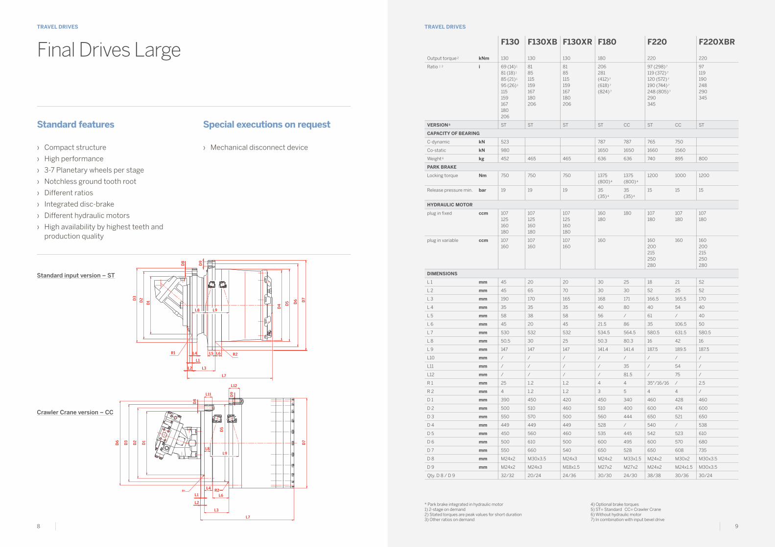
TRAVEL DRIVESTRAVEL DRIVES
Standard features
› Compact structure
› High performance
› 3-7 Planetary wheels per stage
› Notchless ground tooth root
› Different ratios
› Integrated disc-brake
› Different hydraulic motors
› High availability by highest teeth and production quality
Special executions on request
› Mechanical disconnect device
Final Drives Large
Standard input version – ST
Crawler Crane version – CC
F130 F130Xb F130XR F180 F220 F220XbR
Output torque 2 kNm 130 130 130 180 220 220
Ratio 1 3 i 69 (14) 1
81 (18) 1
85 (21) 1
95 (26) 1
115159167180206
8185115159167180206
8185115159167180206
206281(412) 7
(618) 7
(824) 7
97 (298) 7
119 (372) 7
120 (572) 7
190 (744) 7
248 (805) 7
290345
97119190248290345
VERSIoN 5 ST ST ST ST CC ST CC ST
CAPACITy oF bEARINg
C-dynamic kN 523 787 787 765 750
Co-static kN 980 1650 1650 1660 1560
Weight 6 kg 452 465 465 636 636 740 895 800
PARk bRAkE
Locking torque Nm 750 750 750 1375 (800) 4
1375 (800) 4
1200 1000 1200
Release pressure min. bar 19 19 19 35 (35) 4
35 (35) 4
15 15 15
HyDRAuLIC MoToR
plug in fixed ccm 107125160180
107125160180
107125160180
160180
180 107180
107180
107180
plug in variable ccm 107160
107160
107160
160 160200215250280
160 160200215250280
DIMENSIoNS
L 1 mm 45 20 20 30 25 18 21 52
L 2 mm 45 65 70 30 30 52 25 52
L 3 mm 190 170 165 168 171 166.5 165.5 170
L 4 mm 35 35 35 40 80 40 54 40
L 5 mm 58 38 58 56 / 61 / 40
L 6 mm 45 20 45 21.5 86 35 106.5 50
L 7 mm 530 532 532 534.5 564.5 580.5 631.5 580.5
L 8 mm 50.5 30 25 50.3 80.3 16 42 16
L 9 mm 147 147 147 141.4 141.4 187.5 189.5 187.5
L10 mm / / / / / / / /
L11 mm / / / / 35 / 54 /
L12 mm / / / / 81.5 / 75 /
R 1 mm 25 1.2 1.2 4 4 35°/16/16 / 2.5
R 2 mm 4 1.2 1.2 3 5 4 4 /
D 1 mm 390 450 420 450 340 460 428 460
D 2 mm 500 510 460 510 400 600 474 600
D 3 mm 550 570 500 560 444 650 521 650
D 4 mm 449 449 449 528 / 540 / 538
D 5 mm 450 560 460 535 445 542 523 610
D 6 mm 500 610 500 600 495 600 570 680
D 7 mm 550 660 540 650 528 650 608 735
D 8 mm M24x2 M30x3.5 M24x3 M24x2 M33x1.5 M24x2 M30x2 M30x3.5
D 9 mm M24x2 M24x3 M18x1.5 M27x2 M27x2 M24x2 M24x1.5 M30x3.5
Qty. D 8 / D 9 32/32 20/24 24/36 30/30 24/30 38/38 30/36 30/24
* Park brake integrated in hydraulic motor1) 2-stage on demand2) Stated torques are peak values for short duration3) Other ratios on demand
4) Optional brake torques 5) ST= Standard CC= Crawler Crane6) Without hydraulic motor7) In combination with input bevel drive

10 11
D3
D2
D1
D3
D6
D2
D1
L6L5L4
L9L8
L7
L9L8
L4 R2L6
L3
L2
L7
L11
L1
L3L2
L1R2R1
D6
D5
D5
D4
D9
D9
D8
D8
D7
D7
L12
TRAVEL DRIVESTRAVEL DRIVES
Standard features
› Compact structure
› High performance
› 3-7 Planetary wheels per stage
› Notchless ground tooth root
› Different ratios
› Integrated disc-brake
› Different hydraulic motors
› High availability by highest teeth and production quality
Special executions on request
› Mechanical disconnect device
Final Drives Large
Standard input version – ST
Crawler Crane version – CC
F260 F280 F360 F420 F440 F560
Output torque 2 kNm 260 280 360 440 440 560
Ratio 3 i 6997168245345(670) 7
(1115) 7
(1784) 7
201 94 (385) 7
128 (446) 7
161 (670) 7
168 (848) 7
186 (1115) 7
223 (1784) 7
242257283490
259 352555637(445) 7
(528) 7
(705) 7
357739(887) 7
VERSIoN 4 ST CC ST ST ST CC CC
CAPACITy oF bEARINg
C-dynamic kN 750 750 1180 1040 1120 1040 1040
Co-static kN 1560 1560 2600 2450 2550 2450 2450
Weight 5 kg 865 895 1037 1080 1500 1300 2000
PARk bRAkE
Locking torque Nm 1000 1000 1650 1700 1000 1700 (1000)* 900
Release pressure min. bar 15 15 15 12 18 15 (7.8)* 13
HyDRAuLIC MoToR
plug in fixed ccm 355
plug in variable ccm 355250
160 250 355 (2x) 160 250160
160
DIMENSIoNS
L 1 mm 21 21 52 100 60 40 40
L 2 mm 45 25 125 100 132 43 43
L 3 mm 170 165.5 125 130 130 255 255
L 4 mm 40 54 40 40 40 40 45
L 5 mm 48 / 65 60 60 25 45
L 6 mm 60 106.5 45 80 80 25 120
L 7 mm 579 631.5 627 658 1026 820 831.5
L 8 mm 18.5 42 89.3 –25 –43.5 80 80
L 9 mm 189.5 189.5 180.4 215 210.7 213 213
L10 mm / / / / / / /
L11 mm / 54 / / / 40 45
L12 mm / 75 / / / 70 70
R 1 mm 2 / 18°/50/5 18°/100/16 10 4 4
R 2 mm / 4 4 10 10 4< 4
D 1 mm 460 428 530 580 660 450 450
D 2 mm 520 474 630 680 744 515 515
D 3 mm 570 521 685 735 795 569 569
D 4 mm 608 / 608 649 670 669 763
D 5 mm 610 523 610 650 674 570 570
D 6 mm 680 570 685 720 744 620 620
D 7 mm 735 608 740 775 795 670 670
D 8 mm M30x2 M30x2 M30x3.5 M30x3.5 M30x2 M36x3 M36x1.5
D 9 mm 33 M24x1.5 M30x3.5 M30x3.5 M30x2 M30x3 M30x1.5
Qty. D 8 / D 9 24/24 30/36 28/28 30/30 42/42 30/30 29/42
* Park brake integrated in hydraulic motor1) 2-stage on demand2) Stated torques are peak values for short duration3) Other ratios on demand
4) Optional brake torques 5) ST= Standard CC= Crawler Crane6) Without hydraulic motor7) In combination with input bevel drive

12 13
D6
D8
D3
D2
D1
D3
D2
D1
D4
D6
D5
D5
D7
D7
D9
D8 D
9
R1
R1 R2
R2
L10L2
L2
L1L4 L5
L6
L1L4
L8L9
L3L7
L10
L8L9
L3L7
L6
L12L11
TRAVEL DRIVESTRAVEL DRIVES
Standard features
› Compact structure
› High performance
› 3-7 Planetary wheels per stage
› Notchless ground tooth root
› Different ratios
› Integrated disc-brake
› Suitable for various hydraulic motors
› High availability by highest teeth and production quality
Special executions on request
› Mechanical disconnect device
Final Drives XLarge
Standard input version – ST
Crawler Crane version – CC
F620 F650 F700 F700A F800
Output torque 1 kNm 620 650 700 700 800
Ratio 2 i 249 293 328462
682 377 648 283298
VERSIoN 3 ST CC CC CC CC ST
CAPACITy oF bEARINg
C-dynamic kN 1320 1320 1040 1320 1320 2485
Co-static kN 3150 3150 2450 3150 3150 5941
Weight 4 kg 2897 2897 1660 3350 3350 3764
PARk bRAkE
Locking torque Nm 1200 1200 1150 1200 1200 *1000
Release pressure min. bar 28 28 17 28 28 *7.8
HyDRAuLIC MoToR
fixed ccm (2x) 250(1x) 500
(2x) 200(2x) 160
(2x) 250 (2x) 250
variable ccm (2x) 250(2x) 280(1x) 500
(2x) 160 (2x) 215 (2x) 250(2x) 280
(2x) 160 (2x) 250(2x) 280
DIMENSIoNS
L 1 mm 50 30 40 30 30 20
L 2 mm 57.5 33 43 33 33 25
L 3 mm 245 405 255 405 405 229
L 4 mm 52.5 96 89 96 96 60
L 5 mm 53 / / / / 58
L 6 mm 75 306 117 306 306 170
L 7 mm 1232 1159 846.5 1283.5 1372.5 1315
L 8 mm 38 99 133 99 99 161/163
L 9 mm 287 287 213 287 287 257/253
L10 mm 341 352.8 / 352.8 474.8 713
L11 mm / 50 45 50 50 /
L12 mm / 65 70 65 65 /
R 1 mm 4 4 4 4 4 6
R 2 mm / 5 4 5 5 8
D 1 mm 730 668 450 668 668 830
D 2 mm 810 726 515 726 726 980
D 3 mm 880 779 563 779 779 1050
D 4 mm 880 / / / / 916
D 5 mm 885 782 570 780 780 920
D 6 mm 965 830 620 850 850 976
D 7 mm 1020 880 763 900 900 1055
D 8 mm M30x2 M36x1.5 M36x1.5 M36x1.5 M36x1.5 M30x2
D 9 mm M30x2 M30x1.5 M30x1.5 M36x1.5 M36x1.5 M30x2
Qty. D 8 / D 9 41/48 30/45 29/42 30/45 30/45 48/48
* Integrated in hydraulic motor 1) Stated torques are peak values for short duration2) Other ratios on demand3) ST= Standard CC= Crawler Crane4) Without hydraulic motor

14 15
D6
D8
D3
D2
D1
D3
D2
D1
D4
D6
D5
D5
D7
D7
D9
D8 D
9
R1
R1 R2
R2
L10L2
L2
L1L4 L5
L6
L1L4
L8L9
L3L7
L10
L8L9
L3L7
L6
L12L11
TRAVEL DRIVESTRAVEL DRIVES
Standard features
› Compact structure
› High performance
› 3-7 Planetary wheels per stage
› Notchless ground tooth root
› Different ratios
› Integrated disc-brake
› Suitable for various hydraulic motors
› High availability by highest teeth and production quality
Special executions on request
› Mechanical disconnect device
Final Drives XLarge
Standard input version – ST
Crawler Crane version – CC
F1100 F1300 F1800 F2200 F3000
Output torque 1 kNm 1100 1300 1800 2200 2916
Ratio 2 i 406 461 656744
552989
699
VERSIoN 3 ST ST ST CC ST CC ST
CAPACITy oF bEARINg
C-dynamic kN 3900 3900 3900 3900 5100 3900 6110
Co-static kN 7650 7650 7650 7650 11600 7650 11900
Weight 4 kg 7220 7400 7500 9000 10736 9000 11500
PARk bRAkE
Locking torque Nm 1750 1750 1200 1200 2300 1200 1700
Release pressure min. bar 20 20 28 28 22 28 12
HyDRAuLIC MoToR
fixed ccm (2x) 250 (2x) 250 (2x) 250 (2x) 355 (2x) 250
variable ccm (2x) 250(2x) 280
(2x) 250 (2x) 280
(2x) 250(2x) 280
(2x) 355 (2x) 250(2x) 280
(2x) 250(2x) 280
DIMENSIoNS
L 1 mm 57 57 54 55 60 55 60
L 2 mm 60 60 60 60 70 60 70
L 3 mm 503 503 310 478 343 478 343
L 4 mm 74 74 74 158 80 158 80
L 5 mm / / 107 / 100 / 100
L 6 mm / / 191.5 239 80 239 80
L 7 mm 1483 1623 1839.5 1785.5 1846 1956,5 2000
L 8 mm 176 176 176 171 217 171 217
L 9 mm 368 368 368 375 376 375 376
L10 mm 713 395.5 615.5 602.5 591 626 606
L11 mm / / / 50 / 55 /
L12 mm / / / 90 / 93 /
R 1 mm 10 10 10 4 10 4 10
R 2 mm 6 6 10 6 10 6 10
D 1 mm 1110 1110 1110 785 1288 785 1288
D 2 mm 1230 1230 1230 851 1400 858 1400
D 3 mm 1310 1310 1310 923 1500 930 1500
D 4 mm 1116 1116 1224 / 1224 / 1224
D 5 mm - 1100 1250 935 1230 935 1230
D 6 mm 1170 1170 1350 1016 1320 1016 1320
D 7 mm 1226 1226 1430 1224 1400 1224 1400
D 8 mm M36x4 M36x4 M36x1.5 M42x2 M42x3 M48x2 M42x3
D 9 mm M30x3.5 M30x3.5 M42x2 M42x2 M42x3 M48x2 M42x3
Qty. D 8 / D 9 48/52 48/52 48/40 40/40 50/48 36/36 50/48
1) Stated torques are peak values for short duration2) Other ratios on demand3) ST= Standard CC= Crawler Crane4) Without hydraulic motor

16 17
TRAVEL DRIVESTRAVEL DRIVES
Standard features
› Compact structure
› High performance
› 3-7 Planetary wheels per stage
› Notchless ground tooth root
› Different ratios
› Integrated disc-brake
› High availability by highest teeth and production quality
Special executions on request
› Mechanical disconnect device
Final Drives Angular Input
Standard input version – ST
Crawler Crane version – CC
D3
D8
L14
L15
L7
L13 L2 L3
L1
L4
L8 L9
R1 R2L5 L6
D2
D1
D4
D6
D5
D7
D9
D6
R1
L14 L7
L15
L3
L6
L9
L12
L11
L8
L4 R2
L2L13
L1
D3
D2
D1 D7
D5
D8
D9
FP100 FP130 FP180 FP220
Output torque 1 kNm 100 130 180 220
Ratio 2 i 426 825 412 248
VERSIoN 3 ST ST ST ST
CAPACITy oF bEARINg
C-dynamic kN 498 523 787 765
Co-static kN 1010 980 1650 1660
Weight kg 410 452 757 915
PARk bRAkE oPTIoNAL
Locking torque 4 Nm 600 750 1375 1200
Release pressure min. bar 15 19 35 15
DIMENSIoNS
L 1 mm 35 45 30 18
L 2 mm 65 45 30 52
L 3 mm 165 190 168 166.5
L 4 mm 28 35 40 40
L 5 mm 53 58 56 61
L 6 mm 43 45 21.5 35
L 7 mm 463 530 534.5 580.5
L 8 mm 32 50.5 50.3 16
L 9 mm 139 147 141.4 187.5
L10 mm / / / /
L11 mm / / / /
L12 mm / / / /
L13 5 mm 115 311 437.5 448
L14 5 mm 215 411 542.5 593
L15 5 mm 678 941 1077 1173.5
L16 5 mm 60 60 75 85
L17 5 mm 215 215 265 300
R 1 mm 12 / 60 25 4 35°/16/16
R 2 mm 5 4 3 4
D 1 mm 390 390 450 460
D 2 mm 460 500 510 600
D 3 mm 500 550 560 650
D 4 mm 407 449 528 540
D 5 mm 408 450 535 542
D 6 mm 460 500 600 600
D 7 mm 500 550 650 650
D 8 mm M24x2 M24x2 M24x2 M24x2
D 9 mm M24x2 M24x2 M27x2 M24x2
Qty. D 8 / D 9 30/24 32/32 20/30 38/38
D 10 5 mm 40 40 50 55
D 10 Key 5 DIN6885A12x8x50
DIN6885A12x8x50
DIN6885A14x9x70
DIN6885A16x10x80
1) Stated torques are peak values for short duration2) Other ratios on demand3) ST= Standard CC= Crawler Crane4) Optional brake torques5) Other dimensions optional

18 19
TRAVEL DRIVESTRAVEL DRIVES
Standard features
› Compact structure
› High performance
› 3-7 Planetary wheels per stage
› Notchless ground tooth root
› Different ratios
› Integrated disc-brake
› High availability by highest teeth and production quality
Special executions on request
› Mechanical disconnect device
Final Drives Angular Input
Standard input version – ST
Crawler Crane version – CC
D3
D8
L14
L15
L7
L13 L2 L3
L1
L4
L8 L9
R1 R2L5 L6
D2
D1
D4
D6
D5
D7
D9
D6
R1
L14 L7
L15
L3
L6
L9
L12
L11
L8
L4 R2
L2L13
L1
D3
D2
D1 D7
D5
D8
D9
FP360 FP440 FP560 FP900
Output torque 1 kNm 360 440 560 900
Ratio 2 i 446 528 450 406
VERSIoN 3 ST CC CC CC
CAPACITy oF bEARINg
C-dynamic kN 1040 1040 1040 2800
Co-static kN 2450 2450 2450 6390
Weight kg 1065 1300 2222 3750
PARk bRAkE oPTIoNAL
Locking torque 4 Nm 1700 1700 900 /
Release pressure min. bar 12 15 13 /
DIMENSIoNS
L 1 mm 100 40 40 30
L 2 mm 100 43 43 33
L 3 mm 130 255 255 405
L 4 mm 40 40 45 96
L 5 mm 60 / / /
L 6 mm 60 120 120 306
L 7 mm 657.5 814 831.5 965
L 8 mm -25 80 80 129
L 9 mm 215 213 213 258.5
L10 mm / / / /
L11 mm / 40 45 50
L12 mm / 70 70 68
L13 5 mm 380 255 857 612
L14 5 mm 545 400 1104 859
L15 5 mm 1202.5 1214 1935.5 1824
L16 5 mm 110 85 160 120
L17 5 mm 387 300 570 540
R 1 mm 18°/100/16 4 4 4
R 2 mm 10 4 4 5
D 1 mm 580 450 450 668
D 2 mm 680 515 515 726
D 3 mm 735 569 569 779
D 4 mm 649.5 / / /
D 5 mm 650 570 570 780
D 6 mm 720 620 620 850
D 7 mm 775 670 763 900
D 8 mm M30x3.5 M36x1.5 M36x1.5 M36x1.5
D 9 mm M30x3.5 M30x2 M30x1.5 M36x1.5
Qty. D 8 / D 9 30/30 29/42 29/42 30/45
D 10 5 mm 60 55 90 75
D 10 Key 5 DIN6885A18x11x100
DIN6885A16x10x80
DIN6885A25x14x150
DIN6885A25x14x150
1) Stated torques are peak values for short duration2) Other ratios on demand3) ST= Standard CC= Crawler Crane4) Optional brake torques5) Other dimensions optional

20 21
TRAVEL DRIVESTRAVEL DRIVES
Final Drives 2 – Speed
1– Oil filling plug M22×1.5
2– Oil draining plug M22×1.5
3– Low speed clutch port R1/4"G acc. DIN3852 “X”
4– High speed clutch port R1/4"G acc. DIN3852 “X”
5– Flushing oil input port M22×1.5 DIN3852 “X”
6– Flushing oil output port M22×1.5 DIN3852 “X”
PoRT PRESSuRE FuNCTIoN
3 40 bar Small clutch piston pressurized T/M ratio lowgear
4 40 bar Large clutch piston pressurized T/M ratio highgear
3 & 4 0 bar Large & small clutch engaged, T/M in park break position
Project related installation drawings can be available on request.
Dimensions and technical data are subject to change due to continuous product development
Technical data
Output torque max. Nm 40000
Input speed max. RPM 3500
Applicable hydraulic motors
Bosch-rexroth A6VE55 ~ 107 range
Linde HMV 55 ~ 75 range
Sauer danfoss 51C 060 ~ 080 range
Ratio combinations
SHIFTINg STAgE VERSIoNS SHIFTINg STAgE RATIo ISS
1 5.77
2 5.42
3 4.87 *
4 4.44
5 4.26
6 3.81
MAIN STAgE VERSIoNS SHIFTINg STAgE RATIo IMS
A 19.25
B 26 *
C 32.14
All ratios iSS combinable with all ratios iMsFinal ratio if = iSS*iMS* Preferred ratios
Brake torque at input shaft
Nm 600
Brake torque at output min.
Nm 40000
Clutch operating pressure
bar 40 ~ 60
Oil quantity l 3.3
Weight kg 186
Technical features
› Two gear shifting transmission
› Wet disc clutch unit
› Power shift capability
› Hydraulic controlled shifting
› Integrated park & emergency brake
› Optional cooling flow to input stage and clutch unit
› Different hydraulic motors
› Wide variety of ratio combinations
Applications
› Road paving machines
› Construction machines
› Cranes
› Drilling machines
› Winches
› Agricultural machines
› Forestry machines
“A”= 94 for hydraulic motors:Sauer 51C080 D3
Linde HMV75Rexroth A6VE80
“A”= 124 for hydraulic motors:Sauer 51C110Rexroth A6VE107
M20x1.516 stud sor 16 bores
1
2
Ø37
5
Ø29
6
Ø30
0
4540
60∞
193 (Base of bearing)
20391"A "
30
15 7.5 bearing center line
37
Ø35
0
Ø43
5
Ø30
4
TotalStatic load ratingC °=670 [kN]Dynamic load ratingC=395 [kN]
Hydraulic motor screwengagement depth 22
5
3 4
6
2 holes
R137.5
R1 3
1 .5
Ø 340
M2 0
M 2 0 16 holes
224
44
22. 5°
57 °

22 23
D6
D7
D5
D4
D6
D5
D4
D8
D9
D2
D2
D1
D1
D3
D9
D8
D3
D7
L1
L10
L8 L9
L6
R2R1
L2
L1L2
L4 L3
L5
L5L4L5
L7
L7
L6
L6
TRAVEL DRIVESTRAVEL DRIVES
Wheel Drives
Standard features
› Compact structure
› High performance
› 3-7 Planetary wheels per stage
› Notchless ground tooth root
› Different ratios
› Integrated disc-brake
› High availability by highest teeth and production quality
Proven applications
› Towbarless aircraft tractor
› Straddle carriers
› Agricultural machines
› Logging machines
› Forklifts
Special executions on request
› Mechanical disconnect device
Version A
Version B
FR 20 FR 40 FR 60
Output torque (Max) 1 kNm 20 40 60
Output torque (Nominal) kNm 16 23 30
Ratio 2 i 2834
3032
2934
VERSIoN A B A
CAPACITy oF bEARINg
C-dynamic kN 194 300 352
Co-static kN 325 560 735
INPuT ToRquE MAX. Nm 560 715 1066
Weight 4 kg 129 173 500
HyDRAuLIC MoToR 3 ccm 80 107 160
variable 105
operating pressure max. p bar 420 420 420
SERVICE bRAkE Multi-disk brake Multi-disk brake Multi-disk brake
Pressure max. bar 100 110 90
Locking torque dyn. Nm 9500 13000 28000
PARk bRAkE Multi-disk brake Multi-disk brake Multi-disk brake
Release pressure max. bar 80 80 60
Release pressure max. bar 40 40 25
Locking torque max. stat. Nm 24480 23000 30000
DIMENSIoNS
L1 mm 318 441 520
L2 mm 141 135.7 270
L3 mm / 52.7 /
L4 mm 9 80 10
L5 mm 7 43 7
L6 mm 50 63 60
L7 mm 177.5 225 240
L8 mm 58 80 156
L9 mm 110 105 173
L10 mm 29 32 37
R1 mm / 5 /
R2 mm / 1 1.6
D1 mm 335 425 425
D2 mm 280.8 f7 371 - 0.2 375f8
D3 mm 375 465 559
D4 mm 270 f8 290f8 290f8
D5 mm 315 367 330
D6 mm 380 405 554
D7 mm 10xM 24x2 M24(6x) M20(4x) 10xM24x2
D8 mm 10xM 22x1.5 18xM22x1.5 24 M22x1.5
D9 mm 279.5 340 356
1) Stated torques are peak values for short duration2) Other ratios on demand3) Other hydraulic motors on request4) Without hydraulic motor

24 25
D5
D3
D4
D1
D2
L1L3L4
e
L5B
L2
z/m
R1
SLEW DRIVESSLEW DRIVES
Slew Drives
Standard features
› Compact structure
› High performance
› Notchless ground tooth root
› Integrated disc-brake
› Suitable for various hydraulic motors
› High availability by highest teeth and production quality
S5 S7 S10 S13 S17 S30 S34 S35 S54 S90 S130
Output torque 1
kNm 5.5 7 10 13.3 17.5 30 34 35 54 90 130
Ratio 2 i 2533
232733
24273136
36 33 45 45 35 48 39 67
Hydraulic motor 3
ccw 283032
455663
45 5663
80 90
56638090
8090
125 160 180 180200
355500
Electric 6
MuLTI-DISC bRAkE
Braking torque
Nm 310 475 475 740 890 1030 1030 1030 1200 3000 2300
Release pressure min.
bar 14 14 14 18 18 18 18 18 38 14 22.5
Output pinion 4
z/mbD 5
10/1095130
10/1179141
12/1290184
10/1499181
11/14109198
12/16154243
12/16154243
12/18160274
13/22230357
16/24182464
13/30230480
10/1079130
12/1079151
13/1085158
11/1499198
11/16109220
12/20188301
16/22177422
11/1079143
13/1079158
13/1094.5155
12/1299184
12/12104184
14/869134
13/1098155
13/10100158
13/1288195
13/12 5
110 5
190 5
15/6.3577112
13/12110190
13/12 5
110 5
190 5
13/14122221
13/1290195
14/12110199
14/16150273
14/12110201
Weight without Motor (appr.)
kg 68 98 108 123 147 168 540 480 528 867 1225 2276
DIMENSIoNS
L 1 mm 60 60 60 71 86 332 332 239 610 80 578
L 2 mm 262 296 306.5 314 340 355 737 785 653 780 730 622
L 3 mm 31 31 36 30(50) 5 50.5 33 33 30 40 173 95
L 4 mm 40 40.5 50 55(75) 5 55 65 65 91 87 199 160
L 5 mm 302 336.5 356.5 364 395(415) 5 410 802 808 744 917 929 1012
D 1 mm 175 230 250 275 275 350 350 400 460 500 630
D 2 mm 260 285 305 335 335 415 415 460 520 640 675
D 3 mm 288 322 335 370 370 450 450 500 562 690 715
D 4 mm 12x17.5 12x17.5 18x17.5 20x17.5 20x17.5 24x22 24x22 24x26 24x26 18x30 34x26
e mm — — — 1 — — — 2 — — —
R 1 mm 6 6 4 4 4 1.6 1.6 10 — — —
1) Stated torques are peak values for short duration2) Other ratios on demand3) Other hydraulic motors on request4) Output Pinion execution acc. to requirement5) Optional 6) Hydraulic motor connection on demand

26 27
D3
D2
D1
D3
D2
D1
D10
D11
D12 D4
D6
D7
D4
D6
D7
D13
D8
D9
D5
L7
L3
L4
L4
L7L3
L5L6
L5 L6
L9L8
D5
L9L8
L11
D8
D9
L11
L1
L2
L1
L2
L10
CuTTER DRIVESCUTTER DRIVES
Cutter Drives Medium
Standard features
› Compact structure
› High performance
› Notchless ground tooth root
› Different ratios
› Integrated disc-brake
› Suitable for various hydraulic motors
› High availability by highest teeth and production quality
Special executions on request
Standard input version – ST
Mechanical Input version – MI
FA30 FA40 FA55 FA80 FA100
Max. cutting torque kNm 8.5 12 16 23 32
Input power kW 80 110 150 220 300
Ratio 1 i 1922
19 16 1922
19 14212226
VERSIoN 2 ST ST MI ST MI ST ST MI
CAPACITy oF bEARINg
C-dynamic kN 132/194 224 224 224 224 300 498 498
Co-static kN 255/325 405 405 405 405 570 1010 1010
Weight kg 86 122 172 163 223 223 330 360
DIMENSIoNS
L1 mm 13 12 10 12 18 20 35 8
L2 mm 25 35 10 25 18 35 35 8
L3 mm 75 91 125 110 136 90 165 182
L4 mm 15 21 55 24 50 22 28 28
L5 mm 29 34 32 34 34 35 51 40
L6 mm 25 26 26 30 30 24 43 43
L7 mm 278.5 327 631.5 374 688.5 414.5 461 843.5
L8 mm 28 38 72 64 90 34 32 27
L9 mm 89 100 100 113 113 123 139 138
L10 mm / / 402 / 421 / / 540
L11 mm 15 21 55 24 50 22 28 28
R1 mm 2.5 2.5 1 1 1 4 12/60 1.6
R2 mm 2.5 2.5 2.5 2.5 2.5 2.5 5 2.5
D1 mm / 270 270 280 280 330 390 325
D2 mm / 310 310 325 325 370 460 380
D3 mm / 345 360 360 360 410 500 415
D4 mm 269 294 294 329 329 374 407 407
D5 mm 270 295 295 350 350 400 408 408
D6 mm 305 335 335 400 400 450 460 460
D7 mm 335 370 370 435 435 490 502 502
D8 mm M16x2 M20x1.5 M20x1.5 M20x1.5 M20x1.5 M24x2 M24x2 M20x2.5
D9 mm 17.5 17.5 17.5 22 22 25 26 26
Qty. D8 / D9 18/18 16/20 16/20 24/20 24/20 20/20 30/24 12/12
D10 mm / / 138 / 138 / / 165
D11 mm / / 110 / 110 / / 130
D12 mm / / 80 / 80 / / 85
D13 mm / / M16x2 / M16x2 / / M16x2
Qty. D13 / / 6 / 6 / / 8
1) Other ratios on demand2) ST – Standard Input / MI – Mechanical Input (Hydraulic Motor)3) Special bearing
28 29
D3
D2
D1
D3
D2
D1
D10
D11
D12 D4
D6
D7
D4
D6
D7
D13
D8
D9
D5
L7
L3
L4
L4
L7L3
L5L6
L5 L6
L9L8
D5
L9L8
L11
D8
D9
L11
L1
L2
L1
L2
L10
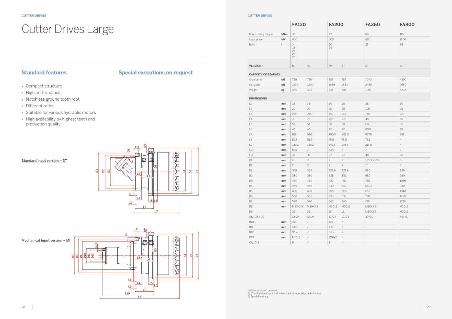
CuTTER DRIVESCUTTER DRIVES
Cutter Drives Large
Standard features
› Compact structure
› High performance
› Notchless ground tooth root
› Different ratios
› Suitable for various hydraulic motors
› High availability by highest teeth and production quality
Special executions on request
Standard input version – ST
Mechanical Input version – MI
FA130 FA200 FA360 FA800
Max. cutting torque kNm 38 47 84 115
Input power kW 400 500 880 1200
Ratio 1 i 14 18 2122 26
2024
25 24
VERSIoN 2 MI ST MI ST ST ST
CAPACITy oF bEARINg
C-dynamic kN 750 750 787 787 1040 4300
Co-static kN 1290 1290 1650 1650 2450 9650
Weight kg 490 426 718 710 1145 4223
DIMENSIoNS
L1 mm 18 18 20 20 35 20
L2 mm 20 20 25 25 100 25
L3 mm 215 215 160 160 130 229
L4 mm 78 78 102 102 40 60
L5 mm 57 57 58 58 60 95
L6 mm 45 45 22 22 80.5 89
L7 mm 913 530 890.5 603.5 657.5 981
L8 mm 81.4 81.4 75.8 75.8 75.1 3)
L9 mm 139.2 139.2 149.4 149.4 214.8 3)
L10 mm 585 / 438 / / /
L11 mm 37 37 37 37 40 60
R1 mm 2 2 2 2 18°/100/16 6
R2 mm 2 2 2 2 10 8
D1 mm 325 325 323.8 323.8 580 830
D2 mm 380 380 381 381 680 980
D3 mm 430 430 482 482 735 1050
D4 mm 449 449 540 540 649.5 930
D5 mm 450 450 605 605 650 1040
D6 mm 500 500 635 635 720 1250
D7 mm 540 540 663 663 775 1329
D8 mm M30x3.5 M30x3.5 M30x2 M30x2 M30x3.5 M30x2
D9 26 26 18 18 M30x3.5 M30x2
Qty. D8 / D9 12/24 12/24 12/24 12/24 30/30 48/48
D10 mm 165 / 165 /
D11 mm 130 / 130 /
D12 mm 85 k6 / 85 k6 /
D13 mm M16x2 / M16x2 /
Qty. D13 8 / 8 /
1) Other ratios on demand2) ST – Standard Input / MI – Mechanical Input (Hydraulic Motor)3) Special bearing

30 31
D9
D7
D4
D6
D5
L5 L6
L3
L10
L7
L1
L8
L9
L4
D14
R1
D1
D8
L11
L2
D12
D11
D13
D2
D3
FLUSHING PORTOIL OUT
SHIFTING PORT50 bar
FLUSHING PORTOIL IN
D10
CuTTER DRIVESCUTTER DRIVES
Cutter Drives 2–Speed
Standard features
› Two speed shifting transmission
› Main drive from proven cutter standard range (FA130/FA200
› Hydraulic shifting unit for gear change
› Cutter main drive & shifting unit modular concept for easy manteinance
Proven applications
› Road rehabilitation
› Surface mining
FA130 - 2S FA200 - 2S
Max. cutting torque kNm 38 47
Input power kW 400 540
VERSIoN 1 2 1 2
Ratio i 21 22.235 19.877 21.05
13.67 18.01 13 17.05
Rotating direction input ccw ccw
CAPACITy oF bEARINg
C-dynamic kN 750 787
Co-static kN 1290 1650
Weight kg 900 1050
SHIFTINg PRESSuRE
min. bar 35 35
max. bar 50 50
DIMENSIoNS
L1 mm 207.65 207.65
L2 mm 25 25
L3 mm 822.2 807.2
L4 mm 413 413
L5 mm 57 32
L6 mm 45 25
L7 optional mm 1418 1378
L8 mm 1442.5 1402.5
L9 mm 688.6 683
L10 mm 139.2 149.4
L11 mm 822.2 1025
R1 mm 40 40
R2 mm 2 2
D1 mm 264.265 264.265
D2 mm 342.9 342.9
D3 mm 393 393
D4 mm 449 533.5
D5 mm 450 590.8
D6 mm 500 641.35
D7 mm 540 679.32
D8 mm 1.25-7 UNC 1.25-7 UNC
Qty. D8 12 12
D9 mm 26 19.84
Qty. D9 24 20
D10 mm 228.6 228.6
D10 optional mm 196.85 196.85
D11 mm 140 140
D11 optional mm 158.75 158.75
D12 mm 140 140
D12 optional mm 120.7 120.7
D13 5/8-11 UNC 5/8-11 UNC
D13 optional STUD 5/8-11 UNF STUD 5/8-11 UNF
Qty. D13 8 8

32 33
WINCH DRIVESWINCH DRIVES
Classification of crane Torque conversion factors kaccording to FEM 1.001 3rd edition,Section 1
Hoisting Slewing boom Activation
Trolley Travelling
Crane Travelling
Erection cranes M 2 - M 3 M 2 - M 3 M 1 - M 2 M 1 - M 2 M 2 - M 3
Loading bridges hook M 5 - M 6 M 4 — M 4 - M 5 M 5 - M 6
Loading bridges grab or magnet
M 7 - M 8 M 6 — M 6 - M 7 M 7 - M 8
Workshop cranes M 6 M 4 — M 4 M 5
Overhead travelling cranes,ram cranes, scrap yard cranes
grab or magnet
M 8 M 6 — M 6 - M 7 M 7 - M 8
Unloading bridges, container gantry cranes
hook or spreader
M 6 - M 7 M 5 - M 6 M 3 - M 4 M 6 - M 7 M 4 - M 5
Other gantry cranes (with trolley and/or live ring)
hook M 4 - M 5 M 4 - M 5 — M 4 - M 5 M 4 - M 5
Unloading bridges,container gantry cranes (with trolley and/or live ring)
grab or magnet
M 8 M 5 - M 6 M 3 - M 4 M 7 - M 8 M 4 - M 5
Berth cranes, shipyard cranes, dismantling cranes
hook M 5 - M 6 M 4 - M 5 M 4 - M 5 M 4 - M 5 M 5 - M 6
Dockside cranes (slewable, gantry type, …), floating cranes, floating sheerlegs
hook M 6 - M 7 M 5 - M 6 M 5 - M 6 — M 3 - M 4
Dockside cranes (slewable, gantry type, …), floating cranes, floating sheerlegs
grab or magnet
M 7 - M 8 M 6 - M 7 M 6 - M 7 — M 4 - M 5
Floating cranes and floating sheerlegs for very high loads (normally above 100 t)
M 3 - M 4 M 3 - M 4 M 3 - M 4 — —
Shipboard cranes hook M 4 M 3 - M 4 M 3 - M 4 M 2 M 3
Shipboard cranes grab or magnet
M 5 - M 6 M 3 - M 4 M 3 - M 4 M 4 - M 5 M 3 - M 4
Tower cranes for construction sites
M 4 M 5 M 4 M 3 M 3
Derrick tower gantry M 2 - M 3 M 1 - M 2 M 1 - M 2 — —
Railroad cranes, approved for service in trains
M 3 - M 4 M 2 - M 3 M 2 - M 3 — —
Vehicle-mounted cranes hook M 3 - M 4 M 2 - M 3 M 2 - M 3 — —
T2 T3 T4 T5 T6 T7 T8
Average usage per day [h] 0.25 - 0.5 0.5 - 1 1 - 2 2 - 4 4 - 8 8 - 16 about 16
Total service life [h] 400 - 800 800 - 1600 1600 - 3200 3200 - 6300 6300 - 12500 12500 - 25000 25000 - 50000
DuTy CyCLE LoAD CLASS MACHINE CLASS & ToRquE CoNVERSIoN FACToR k
L1 light M 11.24
M 21.24
M 31.11
M 41.11
M 50.95
M 60.91
M 70.85
L2 medium M 21.24
M 31.24
M 41.08
M 51
M 60.87
M 70.80
M 80.67
L3 heavy M 30.98
M 40.95
M 50.91
M 60.80
M 70.71
M 80.59
M 80.56
L4 extremely heavy M 40.80
M 50.75
M 60.71
M 70.63
M 80.56
M 80.5
M 80.44
Definition of Nominal Torque TNom
– Drum output speed 25 rpm
– FEM class M5 / T5 / L2
Torque calculation Teff
for alternative FEM – class
Teff = K × TNom
K: torque conversion factor
Additional check – conditions
1- For all machine classes > M5 (M6-M8): to be checked, whether drum output speed 25rpm must be reduced. Refer to Carraro Sales or Application engineering.
2- Brake torque safety must be checked upon formula:
TBrake × i V = > 1.6 Teff
TBrake: brake torque at drive input
i: drive ratio
If brake safety < 1.6 refer to Carraro Sales or Application engineering.

34 35
D1
D2D3
D6
D7
L2
R1
R2
L7
L
Z
8 L9
D4
L3
D9
D9
D8
L4
L5 L6
D5
Detail ZFlange version A
Flange version B
WINCH DRIVESWINCH DRIVES
Winch Drives Small
Standard features
› Compact structure
› Robust layout of planetary gear unit
› Robust taper roller bearings for drum support and cable pull
› Integrated disc-brake
› Easy oil change from front side
› Easy drum mounting
› High variety of ratios and hydraulic motors
1) Other ratios on demand2) Without Hydraulic motor3) Optional brake torques on demand
FW10 FW13 FW30 FW40 FW40A
Nominal torqueTNom (M5 / T5 / L2)
kNm 5.4 7.25 17.6 20 20
Ratio 1 i 3551
93 108122140178229
61 66 81 90101114121137171228305
61 66 81 85101110117124142181
61 66 81 85101110117124142181
CAPACITy oF bEARINg
C-dynamic kN 132 132 132/194 224 224
Co-static kN 255 255 255/325 405 405
Weight 2 kg 45 50 94 115 123
MuLTI-DISk bRAkE
Locking torque version 3 Nm 200 200 300 / 400 420 420
Release pressure min. bar 17 17 16 / 22 18 18
HyDRAuLIC MoToR
plug in fixed ccm 283032
283032
2830324045566063
40455660
8090
plug in variable ccm 2845
2845
285560
5560
80
DIMENSIoNS
L 1 mm 10 10 13 16 13
L 2 mm 30 30 25/22 16 35
L 3 mm 72 72 75 91 91
L 4 mm 13.5 13.5 15 21 21
L 5 mm 15 15 29 34 34
L 6 mm 16 16 25 26 26
L 7 mm 230 255 323/320 338 357
L 8 mm 28 28 28.5 38 38
L 9 mm 79 79 89 100 100
R 1 mm 0.6 0.6 2.5 2.5 2.5
R 2 mm 0.6 0.6 2.5 2.5 2.5
D 1 mm 190 190 240 240 270
D 2 mm 230 230 275 285 310
D 3 mm 256 256 304 320 345
D 4 mm 216 216 269 294 294
D 5 mm 220 220 270 295 295
D 6 mm 260 260 305 335 335
D 7 mm 290 290 335 370 370
D 8 mm M16x2 M16x2 M16x2 M16x1.5 M16x1.5
D 9 Version A mm M16x2 M16x2 M16x2 M16x1.5 M16x1.5
D 9 Version B mm 17 17 17 17.5 17.5
Qty. D 8 / D 9 12/8 12/8 18/18 20/20 16/20

36 37
D1
D2D3
D6
D7
L2
R1
R2
L7
L
Z
8 L9
D4
L3
D9
D9
D8
L4
L5 L6
D5
Detail ZFlange version A
Flange version B
WINCH DRIVESWINCH DRIVES
Winch Drives Medium
Standard features
› Compact structure
› Robust layout of planetary gear unit
› Robust taper roller bearings for drum support and cable pull
› Integrated disc-brake
› Easy oil change from front side
› Easy drum mounting
› High variety of ratios and hydraulic motors
FW55 FW55A FW55b FW80 FW100
Nominal torqueTNom (M5 / T5 / L2)
kNm 25.4 25.4 25.4 42.8 70
Ratio 1 i 63 68 87 94 117124 137 148 185
63 68 87 94 117124 137 148 185
63 68 87 94 117124 137 148 185
61 81101114121137147171187206
77 8495121142175192226
CAPACITy oF bEARINg
C-dynamic kN 224 224 224 300 498
Co-static kN 405 405 405 570 1010
Weight 2 kg 165 177 181 255 330
MuLTI-DISk bRAkE
Locking torque version 3 Nm 420 / 500 420 / 500 420 / 500 600 / 1000 600 / 1500
Release pressure min. bar 15 / 21 15 / 21 15 / 21 18 / 28 15 / 41
HyDRAuLIC MoToR
plug in fixed ccm 8090
40455660
8090107110160180
107125160180
plug in variable ccm 80 5560
107110
80107110160
107110160
DIMENSIoNS
L 1 mm 12 20 12 20 35 / 37
L 2 mm 25 30 37 35 35 / 37
L 3 mm 110 91 110 90 165
L 4 mm 24 24 24 22 28
L 5 mm 36 36 36 37 53
L 6 mm 30 30 30 24 43
L 7 mm 413 399 425 415 461 / 463
L 8 mm 64 45 64 34 32
L 9 mm 113 113 113 123 139
R 1 mm 1 4 1 4 10 (12) / 60
R 2 mm 2.5 2.5 2.5 2.5 5
D 1 mm 280 240 290 330 390
D 2 mm 325 285 335 370 460
D 3 mm 360 320 370 410 500
D 4 mm 340 340 340 374 407
D 5 mm 350 350 350 400 408
D 6 mm 400 400 400 450 460
D 7 mm 435 435 435 490 500
D 8 mm M20x1.5 M20x1.5 M20x1.5 M24x2 M24x2
D 9 Version A mm M20x1.5 M20x1.5 M20x1.5 M24x2 M24x2
D 9 Version B mm 22 22 22 26 26
Qty. D 8 / D 9 24/20 20/20 20/20 20/20 30/24
1) Other ratios on demand2) Without Hydraulic motor3) Optional brake torques on demand

38 39
D1
D2D3
D6
D7
L2
R1
R2
L7
L
Z
8 L9
D4
L3
D9
D9
D8
L4
L5 L6
D5
Detail ZFlange version A
Flange version B
WINCH DRIVESWINCH DRIVES
Winch Drives Large
Standard features
› Compact structure
› Robust layout of planetary gear unit
› Robust taper roller bearings for drum support and cable pull
› Integrated disc-brake
› Easy oil change from front side
› Easy drum mounting
› High variety of ratios and hydraulic motors
1) Other ratios on demand2) Without Hydraulic motor3) Optional brake torques on demand
FW130 FW180 FW220 FW260 FW360
Nominal torqueTNom (M5 / T5 / L2)
kNm 100 112.5 140 175 210
Ratio 1 i 8185115159167180206
206281
97119165190248290345
6997245251345
2494128223257490
CAPACITy oF bEARINg
C-dynamic kN 523 787 765 750 1040
Co-static kN 980 1650 1660 1560 2450
Weight 2 kg 452 636 740 865 1080
MuLTI-DISk bRAkE
Locking torque version 3 Nm 750 / 2200 1200 1200 1000 1700
Release pressure min. bar 19 / 23 35 15 15 12
HyDRAuLIC MoToR
plug in fixed ccm 107125160180
180 107180
355
plug in variable ccm 107160
160200250
355250
355
DIMENSIoNS
L 1 mm 45 30 18 21 100
L 2 mm 45 30 52 45 100
L 3 mm 190 168 166.5 170 130
L 4 mm 35 40 40 40 40
L 5 mm 58 56 61 48 60
L 6 mm 45 21.5 35 60 80
L 7 mm 530 534.5 580.5 579 658
L 8 mm 50.5 50.3 16 18.5 -25
L 9 mm 147 141.4 187.5 189.5 215
R 1 mm 25 4 35°/16/16 2 18°/100/16
R 2 mm 4 3 4 / 10
D 1 mm 390 450 460 460 580
D 2 mm 500 510 600 520 680
D 3 mm 550 560 650 570 735
D 4 mm 449 528 540 608 649
D 5 mm 450 535 542 610 650
D 6 mm 500 600 600 680 720
D 7 mm 550 650 650 735 775
D 8 mm M24x2 M24x2 M24x2 M30x2 M30x3.5
D 9 Version A mm M24x2 M24x2 M24x2 M30x2 M30x3.5
D 9 Version B mm 26 26 26 32 32
Qty. D 8 / D 9 32/32 30/30 38/38 24/24 30/30

German Technology
o&k AntriebstechnikgmbHNierenhofer Str. 10D-45525 Hattingen, GermanyP +49 2324 205 01F +49 2324 205 [email protected]
www.oundka.com
Project related installation drawings can be made available on request as dimensions and technical data are subject to change due to continuous development.


![Prelude and Fugue in E Minor [BWV 847] - Free-scores.com · i i j i j a ] k k [m m k k k k o n i k k m k o ` ` k k k y i k k \ y ` i k n i i j i j a k b k b k k k k k o o o o y o](https://static.fdocuments.in/doc/165x107/60da3b7749c1a759d77b60fe/prelude-and-fugue-in-e-minor-bwv-847-free-i-i-j-i-j-a-k-k-m-m-k-k-k-k-o.jpg)