
Bevel Gearboxes - · PDF fileBevel Gearboxes Product Selection Guide R O N ... Pvt. Ltd. In...
12
Bevel Gearboxes Product Selection Guide R N O I T A C I F I T R E C Y T I L A U Q T V N ISO 9001 - 2008 KEMA NVT - QC CERTIFICATE No. 2033535 DUTCH COUNCIL FOR ACCREDITATION ISO : 9001 - 2008
Transcript of Bevel Gearboxes - · PDF fileBevel Gearboxes Product Selection Guide R O N ... Pvt. Ltd. In...
Bevel Gearboxes
Product Selection Guide
R
NOITACI
FIT
RE
C
YTI
LA
UQ
TVN
ISO 9001 - 2008
KEMA NVT - QC
CERTIFICATE No. 2033535
DUTCH COUNCIL FOR ACCREDITATION
ISO : 9001 - 2008
CONTENTS / INTRODUCTION
2 Gears and Gear Drives (I) Pvt. Ltd.
In the field of power transmission, Bevel Gearboxes
have a special place because of their ability to change
the direction of power transmission, usually to 90°. Bevel
gearboxes can also transmit high torque at high speed
with low power loss unlike worm gearboxes. Gears &
Gear Drives offer straight Bevel gearboxes of different
versions and ratings enabling appropriate solutions to all
kinds of power transmission problems.
Gears & Gear Drives, with over 30 years of experience,
provide products, solutions and services in Power
Transmission Technology. Other products of Gears &
Gear Drives include Worm Gear screw Jacks, Electro
Mechanical Linear Actuators, Bevel Gear Screw Jacks,
Electric cylinders, Geared motors, Universal Joints and
custom designed Gear Units.
IntroductionContents
Introduction 2
Application 3
Design Principle 4
Over view of Types 5
Selection Criteria 6
Preliminary Selection Table 7
Dimension Sheet 8
R

APPLICATION
Primary Purpose Industrial Application
The primary purposes of Bevel Gearboxes are many
fold. Two or more purposes are combined frequently.
Printing machines
Plastic extruders
Conveyors
Packaging machines
Gate valves
Lifts / hoists
Mobile Applications
Commercial movers
Scissors Lift
Cranes
Miscellaneous Applications
Pump drives
Fan/ blowers
Mining equipment
Dryers
Food processing equipment
Agricultural
Lifting systems
3 Gears and Gear Drives (I) Pvt. Ltd.
Transmitting Power At 90°
Splitting Power
Decreasing Speed & Increasing Torque
IN:250 rpm &220 Nm
OUT: 125 rpm &440 Nm
2:1 Reduction
Increasing Speed &Decreasing Torque
IN: 250 rpm &400Nm
OUT:500 rpm &200 Nm
1:2 Speed-Up
OUT
IN
OUT
IN
OUT
OUT
IN
OUT
IN
Functioning as a Power Take-off Devicewith the Cross-shaft as a Common Input
IN
OUT OUT
R
DESIGN PRINCIPLE
Housing Input, Output Shafts
Seals
Bevel Gears
Lubricant
Design Advantages
Bearings
Six models in modular design
Easy to mount electric motor or hydraulic
motor
Solid, hollow shaft designs for universal
application
Can be turned upside down due to
symmetry in mounting
4 Gears and Gear Drives (I) Pvt. Ltd.
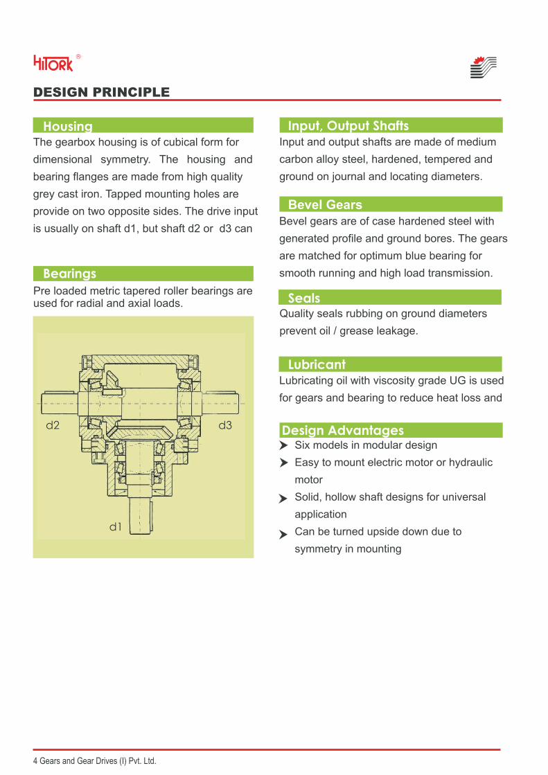
The gearbox housing is of cubical form for
dimensional symmetry. The housing and
bearing flanges are made from high quality
grey cast iron. Tapped mounting holes are
provide on two opposite sides. The drive input
is usually on shaft d1, but shaft d2 or d3 can
Input and output shafts are made of medium
carbon alloy steel, hardened, tempered and
ground on journal and locating diameters.
Bevel gears are of case hardened steel with
generated profile and ground bores. The gears
are matched for optimum blue bearing for
smooth running and high load transmission.
Quality seals rubbing on ground diameters
prevent oil / grease leakage.
Lubricating oil with viscosity grade UG is used
for gears and bearing to reduce heat loss and
Pre loaded metric tapered roller bearings are used for radial and axial loads.
d1
d3d2
R
OVER VIEW OF TYPES
5 Gears and Gear Drives (I) Pvt. Ltd.
R
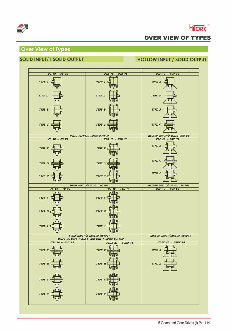
Over View of Types
SOLID INPUT/1 SOLID OUTPUT HOLLOW INPUT / SOLID OUTPUT

SELECTION CRITERIA
Directions of Rotation
Torque and Power Calculation
Maximum input power required is calculatedfrom
P = P1 x C1 x C2
Where,
P = maximum input power to bevel gearbox kWP1 = Power to be transmittedC1 = Shock load factor (Table)C2 = Ambient temperature factor (Table)
From calculated input power P, calculate output torque M2
Where,M2 = Output torque, NmP = Input power, kW0.95= Efficiency of gearboxn2 = Output speed, rpm
In the performance Table maximum input power P(kW) to gearbox, input speed n1(rpm)
Ambient temperature factor C2
Ambient temperature C2
0 to 20°C
20 to 30°C
30 to 40°C
40 to 60°C
1
1.1
1.2
1.4
Shock load factor C1UniformSpeed
No. of workinghrs/day
MediumShocks
HeavyShocks
8
12
24
1.08
1.2
1.3
1.3
1.45
1.6
1.6
1.7
1.82
Output speed n2 (rpm) and output torque
M2 (Nm) are given for easy selection of
gearbox.
6 Gears and Gear Drives (I) Pvt. Ltd.
With reference to direction of rotation of input
shaft, direction of rotation of output shaft is
given below depending upon position of
The direction of rotation is given considering
view towards the shaft under consideration.
n2 M2 = 9550 PX 0.95
R
X
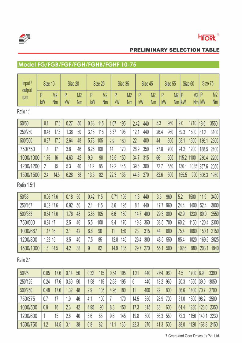
PRELIMINARY SELECTION TABLE
Model FG/FGB/FGF/FGH/FGHB/FGHF 10-75
Ratio 1:1
Ratio 1.5:1
Ratio 2:1
Input /outputrpm
Size 10
P M2kW Nm
Size 20
P M2kW Nm
Size 25
P M2kW Nm
Size 35
P M2kW Nm
Size 45
P M2kW Nm
Size 55
P M2kW Nm
Size 60
P M2kW Nm
Size 75
P M2kW Nm
50/50
50/33
50/25
250/250
250/167
250/125
500/500
500/333
500/250
750/750
750/500
750/375
1000/1000
1000/667
1000/500
1200/1200
1200/800
1200/600
1500/1500
1500/1000
1500/750
0.1 17.6
0.06 17.6
0.48 17.6
0.32 17.6
0.97 17.6
0.64 17.6
1.4 17
0.94 17
1.76 16
1.17 16
2 15
1.32 15
2.4 14.5
1.6 14.5
0.27 50
0.18 50
1.38 50
0.92 50
2.64 48
1.76 48
3.8 46
2.5 46
4.63 42
3.1 42
5.3 40
3.5 40
6.28 38
4.2 38
0.63 115
0.42 115 0.71 195 1.6 440 3.5 960 5.2 1500 11.9 3400
3.18 115
2.1 115 3.6 195 8.1 440 17.7 960 24.4 1400 52.4 3000
5.78 105
3.85 105 6.6 180 14.7 400 29.3 800 42.9 1230 89.0 2550
8.26 100
5.5 100 9.4 170 19.3 350 38.5 700 60.2 1150 120.4 2300
9.9 90
6.6 90 11 150 23 315 44 600 75.4 1080 150.1 2150
11.2 85
7.5 85 12.8 145 26.4 300 48.5 550 85.4 1020 169.6 2025
13.5 82
9 82 14.9 135 29.7 270 55.1 500 102.6 980 203.1 1940
1.07 195
5.37 195
9.9 180
14 170
16.5 150
19.2 145
22.3 135
2.42 440
12.1 440
22 400
28.9 350
34.7 315
39.6 300
44.6 270
5.3 960
26.4 960
44 800
57.8 700
66 600
72.7 550
82.6 500
9.0 1710 18.6 3550
39.3 1500 81.2 3100
68.1 1300 136.1 2600
94.2 1200 188.5 2400
115.2 1100 230.4 2200
130.1 1035 257.6 2050
155.5 990 306.3 1950
0.05 17.6
0.24 17.6
0.48 17.6
0.7 17
0.9 16
1 15
1.2 14.5
0.14 50
0.69 50
1.32 48
1.9 46
2.3 42
2.6 40
3.1 38
0.32 115
1.58 115
2.9 105
4.1 100
4.95 90
5.6 85
6.8 82
0.54 195
2.68 195
4.96 180
7 170
8.3 150
9.6 145
11.1 135
1.21 440
6 440
11 400
14.5 350
17.3 315
19.8 300
22.3 270
2.64 960
13.2 960
22 800
28.9 700
33 600
36.3 550
41.3 500
4.5 1700 8.9 3390
20.3 1550 39.9 3050
36.6 1400 70.7 2700
51.0 1300 98.2 2500
64.4 1230 123.0 2350
72.3 1150 140.1 2230
88.0 1120 168.8 2150
R
7 Gears and Gear Drives (I) Pvt. Ltd.

8 Gears and Gear Drives (I) Pvt. Ltd.
DIMENSION SHEET
FG 10 to FG 75
FGH 20 to FGH 75
R

9 Gears and Gear Drives (I) Pvt. Ltd.
TYPE
FG 10
FG 20
FG 25
FG 35
FG 45
FG 60
FG 55
A AB AC AD B BB BC BD CB CC L Ød W(N9) X
132
195
247
326
395
500
445
100
145
181
250
300
360
335
45
76
108
114
152
220
184
65
100
132
152
190
280
220
144
216
268
330
416
534
480
116
176
219
265
336
422
377
44
68
85
100
128
155
137
72
108
134
165
208
267
65
92
108
156
190
295
220
32.5
46
54
78
95
140
110
26
35
48
60
75
110
100
12
20
25
32
38
60
55
4
6
8
10
10
18
16
9.5
16.5
21
27
33
53
49240
MxL
M4x8
M8x12
M10x20
M12x24
M12x24
M16x24
M16x32
FG 75 625 445 280 360 650 527 202 382 180 120 75 20 67.5325 M20x30
TYPE
FGH 20
FGH 25
FGH 35
FGH 45
FG 75
FGH 55
FGH 60
A AB AC AD B BB BC CB CC L Ød Ød1 W(N9)
195
247
326
395
625
445
500
145
181
250
300
445
335
360
76
108
114
152
280
184
220
100
132
152
190
360
220
280
142
176
210
266
410
284
314
136
170
200
256
404
274
310
68
85
100
128
202
137
115
92
108
156
190
382
220
295
46
54
78
95
180
110
140
35
48
60
75
120
100
110
20
25
32
38
75
55
60
18
25
32
35
75
42
60
6
8
10
10
20
16
18
X
16.5
21
27
33
67.5
49
53
Ød2
30
40
45
50
100
80
85
MxL
M8x12
M8x16
M12x24
M12x24
M20x30
M16x32
M16x24
Type FGH Solid Input/Hollow Output
Type FG Solid Input/Solid Output
DIMENSION SHEET
R

10 Gears and Gear Drives (I) Pvt. Ltd.
DIMENSION SHEET
FGB 10 to FGB 75 & FGHB 20 to FGHB 75
FGF 10 to FGF 75
FGHF 20 to FGHF 75
R

11 Gears and Gear Drives (I) Pvt. Ltd.
FGB 10 to FGB 75 & FGHB 20 to FGHB 75
DIMENSION SHEET
Bevel Gearbox Model Size Type Ratio
Model SizeFGFGHFGBFGHB
FGFFGHF
10,20,25,35,45,55,60,7520,25,35,45,55,60,7510,20,25,35,45,55,60,7520,25,35,45,55,60,7510,20,25,35,45,5510,20,25,35,45,55
A BC DE FG HI JK L
1:1
1.5:1
2:1
TYPE
FGB 10
FGB/FGHB20
FGB/FGHB25
FGB/FGHB35
FGB/FGHB45
FGB/FGHB55
FGB/FGHB60
Ød
7
9
11
11
14
18
18
L1
23
25
30
35
45
50
60
L2
120
160
210
230
280
350
385
L3
10
10
15
15
15
30
25
L4
30
35
50
55
65
90
110
L5
60
70
100
110
152
180
220
L6
60
80
105
115
140
175
192.5
L7
100
130
180
200
250
300
335
L8
50
65
90
100
125
150
167.5
L9
75
90
120
136
197
230
280
L10
37.5
45
60
68
78
115
140
L11
42.5
56
69
93
110
140
165
TYPE Ød1 Ød2 Ød3 Ød4 Ød5 L15 L16 L17 L18 W X
11
14
24
28
38
55
FGF 10
FGF 20
FGF 25
FGF 35
FGF 45
FGF 55
----------
FGHF 20
FGHF 25
FGHF 35
FGHF 45
FGHF 55
70
80
95
70
80
95
110
80
95
110
130
95
110
130
180
110
130
180
230
180
230
250
300
85
100
115
85
100
115
130
100
115
130
165
115
130
165
215
130
165
215
265
215
265
300
350
105
120
145
105
120
140
160
120
140
160
200
140
160
200
250
160
200
250
300
250
300
350
400
M4
M4
M4
M6
M6
M6
M8
M8
M8
M8
M8
M8
M8
M10
M10
M10
M12
M16
M16
M12
M12
M12
M12
90
115
145
175
190
250
26 4 410 12.8
35
55
65
85
115
4
4
5
5
5
12
12
15
15
25
5
8
8
10
16
16.3
27.3
31.3
41.3
54.3
FGF 10 to FGF 55 & FGHF 20 to FGHF 55
FGB/FGHB75 22 80 480 30 140 280 240 430 215 360 180 210
R
M N

R
Gears and Gear Drives (India) Pvt. Ltd. (ISO 9001 : 2008 Certified)
No.14, 2nd Main 2nd Cross, Sai Layout, Bhattrahalli, Virgonagar Post,Bangalore - 560049. Tel +91-8088931951
Website : www.gearsandgeardrives.comEmail: [email protected]
Worm Gear Screw Jacks CUBICAL
Worm Gear Screw Jacks CLASSIC
Bevel GearScrew Jacks
Ball Screw Jack
Lifting Systems
ElectricCylinder
UV Joints
Bevel Gear Box, FG Bevel Gear Box, L Drive
Worm Reducer