Off-grid Inverter SUNNY ISLAND 8.0H / 6 · Off-grid Inverter SUNNY ISLAND 8.0H / 6.0H Installation...
156
SI80H-60H-OffGrid-IA-en-11 | IMEN-SI80H | Version 1.1 EN Off-grid Inverter SUNNY ISLAND 8.0H / 6.0H Installation Manual
-
Upload
truongduong -
Category
Documents
-
view
227 -
download
4
Transcript of Off-grid Inverter SUNNY ISLAND 8.0H / 6 · Off-grid Inverter SUNNY ISLAND 8.0H / 6.0H Installation...
SI80H-60H-OffGrid-IA-en-11 | IMEN-SI80H | Version 1.1 EN
Off-grid InverterSUNNY ISLAND 8.0H / 6.0HInstallation Manual


SMA Solar Technology AG Table of Contents
Installation Manual SI80H-60H-OffGrid-IA-en-11 3
Table of Contents1 Information on this Document. . . . . . . . . . . . . . . . . . . . . . . 92 Safety . . . . . . . . . . . . . . . . . . . . . . . . . . . . . . . . . . . . . . . . . 122.1 Intended Use. . . . . . . . . . . . . . . . . . . . . . . . . . . . . . . . . . . . . . . 122.2 Qualification of Skilled Persons . . . . . . . . . . . . . . . . . . . . . . . . 132.3 Safety Precautions. . . . . . . . . . . . . . . . . . . . . . . . . . . . . . . . . . . 143 Scope of Delivery . . . . . . . . . . . . . . . . . . . . . . . . . . . . . . . . 164 Product Description . . . . . . . . . . . . . . . . . . . . . . . . . . . . . . 194.1 Sunny Island . . . . . . . . . . . . . . . . . . . . . . . . . . . . . . . . . . . . . . . 194.2 Type Label . . . . . . . . . . . . . . . . . . . . . . . . . . . . . . . . . . . . . . . . 204.3 Off-Grid Inverter Control Panel . . . . . . . . . . . . . . . . . . . . . . . . . 224.4 Sunny Remote Control . . . . . . . . . . . . . . . . . . . . . . . . . . . . . . . 244.5 Communication . . . . . . . . . . . . . . . . . . . . . . . . . . . . . . . . . . . . . 255 Mounting. . . . . . . . . . . . . . . . . . . . . . . . . . . . . . . . . . . . . . . 265.1 Organising Mounting . . . . . . . . . . . . . . . . . . . . . . . . . . . . . . . . 265.2 Selecting the Mounting Location for the Off-Grid Inverter . . . . 275.3 Mounting the Off-Grid Inverter . . . . . . . . . . . . . . . . . . . . . . . . . 306 Electrical Connection . . . . . . . . . . . . . . . . . . . . . . . . . . . . . 326.1 Overview of the Connection Area . . . . . . . . . . . . . . . . . . . . . . 326.2 Organising the Electrical Connection . . . . . . . . . . . . . . . . . . . . 336.3 Earthing the TN Off-Grid System . . . . . . . . . . . . . . . . . . . . . . . 356.4 Earthing the TT Off-Grid System . . . . . . . . . . . . . . . . . . . . . . . . 356.5 Earthing the Battery. . . . . . . . . . . . . . . . . . . . . . . . . . . . . . . . . . 366.6 Connecting the BatFuse to the Off-Grid Inverter . . . . . . . . . . . . 376.7 Installing Protective Devices for DC Sources. . . . . . . . . . . . . . . 396.8 Connecting PE. . . . . . . . . . . . . . . . . . . . . . . . . . . . . . . . . . . . . . 40

Table of Contents SMA Solar Technology AG
4 SI80H-60H-OffGrid-IA-en-11 Installation Manual
6.9 Connecting the Stand-Alone Grid/Multicluster Box . . . . . . . . . 406.10 Connecting an External Energy Source . . . . . . . . . . . . . . . . . . 436.11 Inserting Filler-Plugs . . . . . . . . . . . . . . . . . . . . . . . . . . . . . . . . . . 446.12 Installing Protective Devices for Loads . . . . . . . . . . . . . . . . . . . 446.13 Installing Protective Devices for AC Sources in the
Stand-Alone Grid . . . . . . . . . . . . . . . . . . . . . . . . . . . . . . . . . . . 456.14 Installing Protective Devices for a Generator . . . . . . . . . . . . . . 456.15 Connecting the Communication . . . . . . . . . . . . . . . . . . . . . . . . 456.15.1 Removing the Cable Feed-Through Plate . . . . . . . . . . . . . . . . . . . . . . . . . . . 456.15.2 Connecting the Sunny Remote Control . . . . . . . . . . . . . . . . . . . . . . . . . . . . . 466.15.3 Connecting the Cable for Internal Communication between Clusters. . . . . . 466.15.4 Connecting the Communication to the Sunny Island Charger 50. . . . . . . . . 476.15.5 Connecting the Communication of the Multicluster Box . . . . . . . . . . . . . . . . 476.15.6 Connecting Control and Measuring Cables for
Multicluster Box. . . . . . . . . . . . . . . . . . . . . . . . . . . . . . . . . . . . . . . . . . . . . . . 486.15.7 Connecting the Cable for Multicluster Communication. . . . . . . . . . . . . . . . . 486.15.8 Connecting RS485 . . . . . . . . . . . . . . . . . . . . . . . . . . . . . . . . . . . . . . . . . . . . 496.15.9 Installing the Cable Feed-Through Plate . . . . . . . . . . . . . . . . . . . . . . . . . . . . 516.16 Connecting the Battery Temperature Sensor. . . . . . . . . . . . . . . 526.17 Connecting the Battery Current Sensor. . . . . . . . . . . . . . . . . . . 536.18 Assignment of Multi-Function Relay. . . . . . . . . . . . . . . . . . . . . . 546.19 Connecting Control Cables for Autostart Generators. . . . . . . . 566.20 Connecting a Signal Generator for Generators
Without Autostart Function . . . . . . . . . . . . . . . . . . . . . . . . . . . . 576.21 Connecting GenMan to the Off-Grid Inverter. . . . . . . . . . . . . . 586.22 Connecting the Control Cables of the Load-Shedding
Contactors. . . . . . . . . . . . . . . . . . . . . . . . . . . . . . . . . . . . . . . . . 606.23 Connecting the Time Control for External Processes . . . . . . . . . 626.24 Connecting Message Devices for Events and
Warning Messages . . . . . . . . . . . . . . . . . . . . . . . . . . . . . . . . . 63

SMA Solar Technology AG Table of Contents
Installation Manual SI80H-60H-OffGrid-IA-en-11 5
6.25 Connecting the Control Cable for the Battery-Room Fan . . . . . 646.26 Connecting the Control Cable for the Electrolyte Pump
of the Battery. . . . . . . . . . . . . . . . . . . . . . . . . . . . . . . . . . . . . . . 656.27 Connecting the Control Cable for the Use of Excess Energy . . 656.28 Connecting the Auxiliary Contact of the Transfer Switch . . . . . 666.29 Connecting the External Generator Request. . . . . . . . . . . . . . . 687 Commissioning . . . . . . . . . . . . . . . . . . . . . . . . . . . . . . . . . . 697.1 Organising Commissioning. . . . . . . . . . . . . . . . . . . . . . . . . . . . 697.2 Checking the Wiring . . . . . . . . . . . . . . . . . . . . . . . . . . . . . . . . . 707.3 Closing the Off-Grid Inverter. . . . . . . . . . . . . . . . . . . . . . . . . . . 747.4 Quick Configuration Guide . . . . . . . . . . . . . . . . . . . . . . . . . . . 757.4.1 Determining the Battery Capacity . . . . . . . . . . . . . . . . . . . . . . . . . . . . . . . . . 757.4.2 Starting the Quick Configuration Guide . . . . . . . . . . . . . . . . . . . . . . . . . . . . 767.4.3 Configuring Single Operation and Single-Cluster Operation . . . . . . . . . . . . 787.4.4 Configuring Multicluster Operation. . . . . . . . . . . . . . . . . . . . . . . . . . . . . . . . 837.5 Switching to Installer Mode . . . . . . . . . . . . . . . . . . . . . . . . . . . 887.6 Switching to Expert Mode . . . . . . . . . . . . . . . . . . . . . . . . . . . . 887.7 Setting Time-Dependent Functions. . . . . . . . . . . . . . . . . . . . . . . 897.8 Setting the Time-Controlled Functions . . . . . . . . . . . . . . . . . . . . 897.9 Setting Load Shedding in a Multicluster System . . . . . . . . . . . . 897.10 Configuration of the Multi-Function Relays . . . . . . . . . . . . . . . . 907.10.1 Use of the Multi-Function Relays . . . . . . . . . . . . . . . . . . . . . . . . . . . . . . . . . . 907.10.2 Setting the Functions of the Multi-Function Relays . . . . . . . . . . . . . . . . . . . . . 917.10.3 Setting 1-Level Load Shedding . . . . . . . . . . . . . . . . . . . . . . . . . . . . . . . . . . . 917.10.4 Setting 2-Level Load Shedding . . . . . . . . . . . . . . . . . . . . . . . . . . . . . . . . . . . 927.10.5 Setting Time-Dependent 1-Level Load Shedding . . . . . . . . . . . . . . . . . . . . . . 937.10.6 Setting Time-Dependent 2-Level Load Shedding . . . . . . . . . . . . . . . . . . . . . . 957.10.7 Setting Time Control for External Processes . . . . . . . . . . . . . . . . . . . . . . . . . 967.10.8 Setting the Control of the Battery-Room Fan . . . . . . . . . . . . . . . . . . . . . . . . . 977.10.9 Setting the Use of Excess Energy . . . . . . . . . . . . . . . . . . . . . . . . . . . . . . . . . 97

Table of Contents SMA Solar Technology AG
6 SI80H-60H-OffGrid-IA-en-11 Installation Manual
7.11 Changing the Battery Protection Mode . . . . . . . . . . . . . . . . . . 987.12 Setting the Resistance of the Battery Cable . . . . . . . . . . . . . . 1007.13 Commissioning the Battery Current Sensor . . . . . . . . . . . . . . . 1017.14 Configuring the Limiting Values for the
Generator Connection . . . . . . . . . . . . . . . . . . . . . . . . . . . . . . 1027.14.1 Changing the Current Limiting Values for the Generator . . . . . . . . . . . . . . 1027.14.2 Changing the Voltage Limiting Values for the Generator . . . . . . . . . . . . . . 1037.14.3 Changing the Frequency Limiting Values of the Generator Voltage . . . . . . 1037.14.4 Changing the Permitted Reverse Power to the Generator. . . . . . . . . . . . . . 1047.14.5 Setting the Current Limit for the Generator Depending on the Frequency . . . . .1047.15 Changing the Type of Generator Interface. . . . . . . . . . . . . . . 1057.16 Configuring Generator Run Times. . . . . . . . . . . . . . . . . . . . . . 1057.16.1 Changing the Warm-Up Time for the Generator . . . . . . . . . . . . . . . . . . . . 1057.16.2 Changing the Minimum Run Time for the Generator . . . . . . . . . . . . . . . . . 1067.16.3 Changing the Shut-Off Delay Time for the Generator. . . . . . . . . . . . . . . . . 1067.16.4 Changing the Minimum Stop Time for the Generator . . . . . . . . . . . . . . . . . 1067.17 Configuring the Generator Request . . . . . . . . . . . . . . . . . . . . 1067.17.1 Changing the Automatic Generator Mode. . . . . . . . . . . . . . . . . . . . . . . . . 1067.17.2 Changing the State-Of-Charge-Dependent Generator Request . . . . . . . . . 1077.17.3 Setting Time-Dependent Generator Request . . . . . . . . . . . . . . . . . . . . . . . . 1077.17.4 Setting Load-Dependent Generator Request . . . . . . . . . . . . . . . . . . . . . . . . 1097.17.5 Time-Controlled Activation of the Generator. . . . . . . . . . . . . . . . . . . . . . . . 1107.17.6 Changing the Generator Request Depending on the
Charging Process of the Battery . . . . . . . . . . . . . . . . . . . . . . . . . . . . . . . . . 1107.17.7 Setting the External Generator Request . . . . . . . . . . . . . . . . . . . . . . . . . . . 1117.18 Setting the Procedure in the Event of an Aborted Start
of the Generator . . . . . . . . . . . . . . . . . . . . . . . . . . . . . . . . . . . 1117.19 Changing the Current Limiting Values for the Electricity Grid . . . 1127.20 Changing the Sleep Mode . . . . . . . . . . . . . . . . . . . . . . . . . . . 1127.21 Setting the Search Mode . . . . . . . . . . . . . . . . . . . . . . . . . . . . 1137.22 Setting the Silent Mode. . . . . . . . . . . . . . . . . . . . . . . . . . . . . . 114

SMA Solar Technology AG Table of Contents
Installation Manual SI80H-60H-OffGrid-IA-en-11 7
7.23 Changing the Automatic Frequency Synchronisation . . . . . . . 1147.24 Functional Test . . . . . . . . . . . . . . . . . . . . . . . . . . . . . . . . . . . . 1157.24.1 Testing Communication Interfaces. . . . . . . . . . . . . . . . . . . . . . . . . . . . . . . . 1157.24.2 Starting the Off-Grid System . . . . . . . . . . . . . . . . . . . . . . . . . . . . . . . . . . . . 1167.24.3 Testing the Battery Current Sensor . . . . . . . . . . . . . . . . . . . . . . . . . . . . . . . 1167.24.4 Testing the Generator . . . . . . . . . . . . . . . . . . . . . . . . . . . . . . . . . . . . . . . . . 1177.24.5 Testing Load Shedding . . . . . . . . . . . . . . . . . . . . . . . . . . . . . . . . . . . . . . . . 1187.24.6 Testing the Frequency Shift Power Control . . . . . . . . . . . . . . . . . . . . . . . . . 1197.25 Charging the Battery. . . . . . . . . . . . . . . . . . . . . . . . . . . . . . . . 1197.26 Completing Commissioning . . . . . . . . . . . . . . . . . . . . . . . . . . 1208 Decommissioning . . . . . . . . . . . . . . . . . . . . . . . . . . . . . . . 1218.1 Disconnecting the Off-Grid Inverter from Voltage Sources . . . 1218.2 Disassembling the Off-Grid Inverter . . . . . . . . . . . . . . . . . . . . 1218.3 Packing the Off-Grid Inverter . . . . . . . . . . . . . . . . . . . . . . . . . 1238.4 Disposal of the Off-Grid Inverter. . . . . . . . . . . . . . . . . . . . . . . 1239 Battery Management. . . . . . . . . . . . . . . . . . . . . . . . . . . . 1249.1 State of the Battery . . . . . . . . . . . . . . . . . . . . . . . . . . . . . . . . . 1249.1.1 Available Battery Capacity . . . . . . . . . . . . . . . . . . . . . . . . . . . . . . . . . . . . . 1249.1.2 Current State of Charge . . . . . . . . . . . . . . . . . . . . . . . . . . . . . . . . . . . . . . . 1249.1.3 Battery Temperature . . . . . . . . . . . . . . . . . . . . . . . . . . . . . . . . . . . . . . . . . . 1249.2 Charge Control . . . . . . . . . . . . . . . . . . . . . . . . . . . . . . . . . . . . 1259.2.1 Charging Phases . . . . . . . . . . . . . . . . . . . . . . . . . . . . . . . . . . . . . . . . . . . . . 1259.2.2 Charging Processes. . . . . . . . . . . . . . . . . . . . . . . . . . . . . . . . . . . . . . . . . . . 1279.2.3 Automatic Temperature Compensation . . . . . . . . . . . . . . . . . . . . . . . . . . . . 128
10 External Energy Sources in the Off-Grid System. . . . . . 12910.1 Generator as an External Energy Source . . . . . . . . . . . . . . . . 12910.2 Electricity Grid as an External Energy Source. . . . . . . . . . . . . 12910.3 Generator and Electricity Grid as External Energy Sources . . 129

Table of Contents SMA Solar Technology AG
8 SI80H-60H-OffGrid-IA-en-11 Installation Manual
10.4 Synchronisation of the Stand-Alone Grid to the External Energy Source. . . . . . . . . . . . . . . . . . . . . . . . . . . . . . 130
10.5 Interactions between External Energy Sources and the Stand-Alone Grid . . . . . . . . . . . . . . . . . . . . . . . . . . . . . . . . . . 130
10.6 Parameters for the Generator and Electricity Grid . . . . . . . . . 13010.7 Generator Management of the Off-Grid Inverter . . . . . . . . . . 13110.7.1 Generator Management Tasks . . . . . . . . . . . . . . . . . . . . . . . . . . . . . . . . . . 13110.7.2 Conditions for Generator Requests . . . . . . . . . . . . . . . . . . . . . . . . . . . . . . . 13110.7.3 Generator Run Times. . . . . . . . . . . . . . . . . . . . . . . . . . . . . . . . . . . . . . . . . . 13210.7.4 Electrical Limiting Values for the Generator . . . . . . . . . . . . . . . . . . . . . . . . 13310.8 Operating Modes for the Generator . . . . . . . . . . . . . . . . . . . 13310.9 Operating Procedure for Generator Control . . . . . . . . . . . . . 13410.9.1 Operating Procedure for Generators with Autostart Function. . . . . . . . . . . 13410.9.2 Operating Procedure for Generators without an Autostart Function. . . . . . 13610.9.3 Operating Procedure for Generators with GenMan. . . . . . . . . . . . . . . . . . 13810.10 Grid Management . . . . . . . . . . . . . . . . . . . . . . . . . . . . . . . . . 14010.10.1 Tasks of Grid Management . . . . . . . . . . . . . . . . . . . . . . . . . . . . . . . . . . . . 14010.10.2 Electrical Limiting Values for the Electricity Grid . . . . . . . . . . . . . . . . . . . . . 14010.10.3 Request Conditions for the Electricity Grid . . . . . . . . . . . . . . . . . . . . . . . . . 14110.11 Operating Modes for the Electricity Grid . . . . . . . . . . . . . . . . 14110.12 Operating Procedure for Grid Control . . . . . . . . . . . . . . . . . . 14211 Accessories . . . . . . . . . . . . . . . . . . . . . . . . . . . . . . . . . . . . 14312 Technical Data . . . . . . . . . . . . . . . . . . . . . . . . . . . . . . . . . 14412.1 Sunny Island 8.0H . . . . . . . . . . . . . . . . . . . . . . . . . . . . . . . . . 14412.2 Sunny Island 6.0H . . . . . . . . . . . . . . . . . . . . . . . . . . . . . . . . . 14913 Contact . . . . . . . . . . . . . . . . . . . . . . . . . . . . . . . . . . . . . . . 154

SMA Solar Technology AG 1 Information on this Document
Installation Manual SI80H-60H-OffGrid-IA-en-11 9
1 Information on this DocumentValidityThis document is valid for the following device types:
• SI8.0H-10• SI8.0H-11• SI6.0H-10• SI6.0H-11
Target GroupThis document is intended for skilled persons. Only skilled persons are allowed to perform the tasks set forth in this document (see Section 2.2 "Qualification of Skilled Persons", page 13).
Additional InformationAdditional information is available at www.SMA-Solar.com:
Symbols
Document title Document typeBattery Management in Off-Grid Systems Technology Brochure 6
Symbol ExplanationIndicates a hazardous situation which, if not avoided, will result in death or serious injuryIndicates a hazardous situation which, if not avoided, could result in death or serious injuryIndicates a hazardous situation which, if not avoided, could result in minor or moderate injuryIndicates a situation which, if not avoided, can result in property damage
Information that is important for a specific topic or goal, but is not safety-relevant
Indicates an essential requirement for achieving a specific goal Desired result A problem that might occur

1 Information on this Document SMA Solar Technology AG
10 SI80H-60H-OffGrid-IA-en-11 Installation Manual
Typographies
Nomenclature
Menus are presented as follows: menu number, hash and menu name (e.g. 150# Compact Meters).Parameters are presented as follows: menu number, full stop, parameter number and parameter name (e.g. 150.01 GdRmgTm). Parameters include both configurable parameters and parameters for displaying values.
Typography Usage Examplebold • Display messages
• Parameters• Connections• Slots• Elements to be selected• Elements to be entered
• Connect PE to AC2Gen/Grid.• Select parameter
235.01 GnAutoEna and set it to Off.
> • Several elements that are to be selected
• Select 600# Direct Access > Select Number.
[Button/Key] • Key on the inverter that is to be selected or pressed
• Press [ENTER].
Complete designation Designation in this documentSunny Island Off-grid inverterSunny Boy PV inverterSunny Mini CentralSunny TripowerWindy Boy Wind power inverter

SMA Solar Technology AG 1 Information on this Document
Installation Manual SI80H-60H-OffGrid-IA-en-11 11
AbbreviationsAbbreviation Designation ExplanationAC Alternating Current ‒DC Direct Current ‒FLA Flooded Lead Acid Batteries ‒FSPC Frequency Shift Power Control ‒LED Light-Emitting Diode ‒MSL Mean Sea Level ‒PV Photovoltaics ‒QCG Quick Configuration Guide ‒SOC State of Charge State of charge of the batterySOH State of Health Battery capacity still availableVRLA Valve Regulated Lead-Acid ‒

2 Safety SMA Solar Technology AG
12 SI80H-60H-OffGrid-IA-en-11 Installation Manual
2 Safety2.1 Intended UseThe Sunny Island is a bidirectional off-grid inverter and forms a stand-alone grid.
Figure 1: Principle of an off-grid system with a Sunny Island and a Sunny Remote Control
The Sunny Island is suitable for use indoors and in outdoor areas that are protected from the elements.For safety reasons, it is not permitted to modify the product or install components that are not explicitly recommended or distributed by SMA Solar Technology AG for this product.Only use the Sunny Island in accordance with the information provided in the enclosed documentation. Any other use may result in personal injury or property damage.
• Do not mount the Sunny Island on flammable construction materials.• Do not mount the Sunny Island in areas containing highly flammable materials.• Do not mount the Sunny Island in potentially explosive atmospheres.
The Sunny Island has been designed for use at elevations of up to 3,000 m above MSL.Life-threatening voltages occur in the Sunny Island.
• Never operate the Sunny Island without the enclosure lid in place.

SMA Solar Technology AG 2 Safety
Installation Manual SI80H-60H-OffGrid-IA-en-11 13
AC sources in the stand-alone grid can be used for energy supply. Too much power from the AC sources in the stand-alone grid can lead to system failures.
• Observe the maximum power from AC sources in the stand-alone grid that can be connected to the AC1 terminal (see Section 12 "Technical Data", page 144). In a cluster, the powers of the individual Sunny Islands are added to yield the total maximum power.
The Sunny Island uses batteries for energy storage. The rated voltage of the battery must correspond to the DC input voltage. If the battery capacity selected is too low, system failures may result.
• Observe the recommendations for the minimum battery capacity connected to the DC terminal (see Section 12 "Technical Data", page 144). For off-grid inverters connected in parallel on the DC side (clusters), the recommended capacities of the individual Sunny Islands added together yield yield the total minimum battery capacity.
A fuse-switch-disconnector, – e.g. a BatFuse, must be installed between the battery and the Sunny Island.DC loads and DC sources can be integrated into the off-grid system. If DC loads or DC sources other than Sunny Island Charger 50 are included, a battery current sensor must be installed. The Sunny Island is not suitable for establishing a DC distribution network.The Sunny Island is not suitable for supplying life-sustaining medical devices.
• Never use the Sunny Island in systems in which a power outage might result in personal injury.The Sunny Island can control various components in an off-grid system via two multi-function relays, e.g. a load-shedding contactor. The multi-function relays are not suitable for controlling functions which may endanger persons in the event of a malfunction in the multi-function relays – for example, if there is insufficient redundancy in the ventilation of the battery room.The enclosed documentation is an integral part of this product.
• Read and observe the documentation.• Keep the documentation in a convenient place for future reference.
2.2 Qualification of Skilled PersonsSkilled persons must have the following qualifications:
• Training in off-grid systems from SMA Solar Technology AG• Training in how to deal with the dangers and risks associated with installing and using electrical
devices and batteries• Training in the installation and commissioning of electrical devices• Knowledge and observance of the local standards and directives• Knowledge and observance of this document and all safety precautions

2 Safety SMA Solar Technology AG
14 SI80H-60H-OffGrid-IA-en-11 Installation Manual
2.3 Safety PrecautionsElectric ShockHigh voltages are present in the off-grid system and in the off-grid inverter. The off-grid inverter can start automatically from standby. Observe the following safety rules before opening the off-grid inverter.
• Switch off or disconnect the components in the following order:– Off-grid inverter– All loads, AC sources, external energy sources and DC sources– Miniature circuit-breakers for AC sources and the external energy source in the
sub-distributions– BatFuse switch-disconnector
• Ensure that the device cannot be reconnected.• Open the enclosure lid and ensure that no voltage is present.• Earth and short-circuit the AC conductors.• Cover or safeguard any adjacent live components.
ExplosionExplosive gases may escape from the battery.
• Protect the surroundings of the battery against open flames, embers or sparks.• Install, maintain and operate the battery according to the manufacturer's specifications.• Do not throw batteries into fire.
Acid Burns and PoisoningIf handled inappropriately, electrolyte from the battery can burn the skin or eyes and/or be poisonous.
• Protect the battery enclosure against destruction.• Do not open or deform the battery.• Whenever working on the battery, wear rubber gloves, rubber boots and goggles.• Rinse acid splashes with clear water and consult a doctor.• Install, maintain and operate the battery according to the manufacturer's specifications.
CrushingMoving parts on the generator can crush or sever body parts. The generator can be started automatically by the off-grid inverter.
• Only operate the generator with the safety equipment.• Install, maintain and operate the generator according to the manufacturer's specifications.

SMA Solar Technology AG 2 Safety
Installation Manual SI80H-60H-OffGrid-IA-en-11 15
Burn HazardsSome parts of the enclosure can become hot during operation.
• During operation, touch the off-grid inverter on the enclosure lid only.
Short-circuit currents in the battery can cause heat build-up and electric arcs. Observe the following safety rules before working on the battery:
• Remove watches, rings and other metal objects.• Use insulated tools.• Do not place tools or metal parts on the battery.
Electrostatic Discharge (ESD)By touching electronic components, you can damage or destroy the off-grid inverter.
• Earth yourself before touching any components.

3 Scope of Delivery SMA Solar Technology AG
16 SI80H-60H-OffGrid-IA-en-11 Installation Manual
3 Scope of DeliveryCheck the delivery for completeness and any externally visible damage. Contact your specialist dealer if the delivery is incomplete or damaged.
Figure 2: Components included in the scope of delivery
Position Quantity DescriptionA 1 Sunny IslandB 2 Ventilation gridC 1 Wall mounting bracketD 2 Hexagon socket screw M6x10E 2 Hexagon socket screw M6x16*F 2 Hexagon socket screw M8x20G 2 Conical spring washer M6*H 1 Clamping bracketI 1 Battery temperature sensorK 2 3-pin terminalL 2 4-pin terminalM 1 Cable gland M20N 1 Counter nut for cable gland M20O 2 Cable gland M25P 2 Counter nut for cable gland M25Q 2 Cable gland M32R 2 Counter nut for cable gland M32S 1 Filler-plug M20

SMA Solar Technology AG 3 Scope of Delivery
Installation Manual SI80H-60H-OffGrid-IA-en-11 17
"Communication for RS485" Order OptionThe following components are added to the scope of delivery.
Figure 3: Components of the "Communication for RS485" order option
T 1 Filler-plug M25U 1 Black RJ45 data cable CAT5e, 2 mV 2 Silicone tube 10 mm x 500 mmW 1 Cable support sleeve for 1 cableX 2 Cable support sleeve for 2 cablesY 1 Installation manual, operating manual, Technical description, Parameter
document, document set with explanations and certificates* 1 spare part for the enclosure lid included
Position Quantity DescriptionA 1 SI-COMSMA.BGx, installed in the Sunny Island* at the factory
* In the case of a cluster system, the communication interface is only installed in the master.
B 1 Grey RJ45 data cable CAT5e, 5 mC 1 White RJ45 data cable CAT5e with three wires with stripped insulationD 1 Screw, installed in the Sunny Island at the factoryE 1 Terminator, plugged into SI-COMSMA.BGx at the factory
Position Quantity Description

3 Scope of Delivery SMA Solar Technology AG
18 SI80H-60H-OffGrid-IA-en-11 Installation Manual
"Communication for Multicluster System" Order OptionThe following components are added to the scope of delivery.
Figure 4: Components of the "Communication for multicluster system" order option
Position Quantity DescriptionA 1 SI-SYSCAN.BGx* , installed in the master at the factory
* CAN communication interface
B 1 SI-COMSMA.BGx** , installed in the master at the factory
** RS485 communication interface
C 1 Yellow RJ45 data cable CAT5e, 5 mD 1 Grey RJ45 data cable CAT5e, 5 mE 1 White RJ45 data cable CAT5e with three wires with stripped insulationF 2 Screw, installed in the Sunny Island at the factoryG 2 Terminator, plugged into SI-SYSCAN.BGx and SI-COMSMA.BGx at the
factory

SMA Solar Technology AG 4 Product Description
Installation Manual SI80H-60H-OffGrid-IA-en-11 19
4 Product Description4.1 Sunny IslandThe Sunny Island is a bidirectional off-grid inverter and forms a stand-alone grid.
Figure 5: Design of the Sunny Island
The Sunny Island supplies AC loads in the stand-alone grid from a battery or charges the battery with the energy provided by sources on the AC side. AC sources in the stand-alone grid (e.g. PV inverters) supply loads and are used by the off-grid inverter to recharge the battery. In order to increase the availability of the stand-alone grid and reduce the battery capacity, the Sunny Island can use and control external energy sources (e.g. a generator) as an energy reserve.The Sunny Island supplies the loads with active power and reactive power. The loads may temporarily overload the Sunny Island. If there is a short circuit in the stand-alone grid, the Sunny Island also briefly feeds short-circuit currents into the stand-alone grid. As a result, the Sunny Island may trip the miniature circuit-breaker. Miniature circuit-breakers only disconnect electric circuits that are affected by the fault.The off-grid system must be a TN or TT system. The Sunny Island does not support IT systems.
Position DescriptionA Ventilation gridB Type labelC Control panelD Enclosure lid

4 Product Description SMA Solar Technology AG
20 SI80H-60H-OffGrid-IA-en-11 Installation Manual
4.2 Type LabelThe type label identifies the off-grid inverter. The type label is located on the right-hand side of the enclosure.
Figure 6: Layout of the type label
The information on the type label is intended to help you in the safe use of the off-grid inverter and will be needed when you contact the SMA Service Line. The type label must remain permanently attached to the off-grid inverter.
Position Description ExplanationA Type Device typeB Serial No. Inverter serial numberC Device-specific characteristics ‒

SMA Solar Technology AG 4 Product Description
Installation Manual SI80H-60H-OffGrid-IA-en-11 21
Symbols on the Type LabelSymbol Description Explanation
Danger to life due to high voltages
The off-grid inverter operates at high voltages. All work on the off-grid inverter must be carried out by skilled persons only (see Section 2.2).
Risk of burns from hot surfaces The off-grid inverter can become hot during operation. Avoid contact during operation. Allow the off-grid inverter to cool down sufficiently before carrying out any work. Wear personal protective equipment such as safety gloves.
Observe the documentation Observe all documentation that is supplied with the off-grid inverter.
DC Direct currentTransformer The off-grid inverter has a transformer.
AC Alternating currentIP54 The off-grid inverter is protected against dust
deposits and water splashes from all angles.Protection class I All enclosure parts are earthed.
Certified safety The off-grid inverter is VDE-tested (Association for Electrical, Electronic and Information Technologies) and complies with the requirements of the German Equipment and Product Safety Act.
CE marking The off-grid inverter complies with the requirements of the applicable EC directives.
Australian mark of conformity The off-grid inverter complies with the requirements of the applicable Australian directives.
Proper disposal Do not dispose of the off-grid inverter together with the household waste.
VD E

4 Product Description SMA Solar Technology AG
22 SI80H-60H-OffGrid-IA-en-11 Installation Manual
4.3 Off-Grid Inverter Control Panel
Figure 7: Layout of the control panel
Position Symbol Description Status ExplanationA Start-stop button
TSS‒ Press the start-stop button to start or
stop the off-grid system. In display messages on the Sunny Remote Control, the start-stop button is referred to as TSS.
B Activation button ‒ Pressing the activation button will switch on the off-grid inverter. After switching on the off-grid inverter, it will enter the standby mode.
C Deactivation button
‒ Pressing the deactivation button will switch off the off-grid inverter.
D Inverter LED Off The off-grid inverter is switched off.Glowing green
The off-grid inverter is in operation.
Glowing orange
The off-grid inverter is in standby mode.
Glowing red The off-grid inverter has switched off due to an error.
Flashing quickly*
The off-grid inverter is not configured.
Flashing slowly**
The off-grid inverter is in sleep mode.

SMA Solar Technology AG 4 Product Description
Installation Manual SI80H-60H-OffGrid-IA-en-11 23
E Grid LED Off No voltage is present at the connection of the external energy source.
Glowing green
External energy source is connected.
Glowing orange
The off-grid inverter is synchronising the stand-alone grid to the external energy source.
Glowing red Error at the external energy source connection.
F Battery LED Glowing green
The battery charge level is over 50%.
Glowing orange
The battery charge level is between 50% and 20%.
Glowing red The battery charge level is below 20%.
G AC operation ‒ Symbol indicates the area for starting and stopping inverter operation.
H Standby ‒ Symbol indicates the area for switching the inverter on and off.
* flashing at intervals of 0.5 s – 1 s** flashing at intervals of 1.5 s – 2 s
Position Symbol Description Status Explanation

4 Product Description SMA Solar Technology AG
24 SI80H-60H-OffGrid-IA-en-11 Installation Manual
4.4 Sunny Remote ControlYou can configure and control the off-grid system centrally with the Sunny Remote Control display. For a multicluster system, each master must be connected to a Sunny Remote Control. Error messages for the individual clusters are configured and displayed on the corresponding Sunny Remote Control.
Figure 8: Layout of the Sunny Remote Control
Position Description ExplanationA Display Four-line display shows operating data (e.g. operating state
or display values) and events, warnings or errors of the off-grid inverter.The display backlight is automatically deactivated after a short time of inactivity.
B Button Pressing the button will turn on the backlight, acknowledge parameters or switch the level within a menu. The return icon on the display indicates when you can perform an action by pressing the button.Turning the button will switch on the backlight, change parameters or navigate within a menu level.
C Slot for SD card ‒
A
B
C
SMA Solar Technology AG 4 Product Description
Installation Manual SI80H-60H-OffGrid-IA-en-11 25
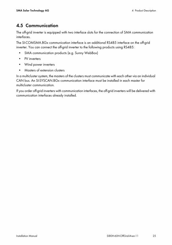
4.5 CommunicationThe off-grid inverter is equipped with two interface slots for the connection of SMA communication interfaces.The SI-COMSMA.BGx communication interface is an additional RS485 interface on the off-grid inverter. You can connect the off-grid inverter to the following products using RS485:
• SMA communication products (e.g. Sunny WebBox)• PV inverters• Wind power inverters• Masters of extension clusters
In a multicluster system, the masters of the clusters must communicate with each other via an individual CAN bus. An SI-SYSCAN.BGx communication interface must be installed in each master for multicluster communication.If you order off-grid inverters with communication interfaces, the off-grid inverters will be delivered with communication interfaces already installed.

5 Mounting SMA Solar Technology AG
26 SI80H-60H-OffGrid-IA-en-11 Installation Manual
5 Mounting5.1 Mounting SequenceProcedure See1 Mount/install the Multicluster Box, if present. Multicluster Box installation
manual2 Select the mounting location for the off-grid inverter and mount
the off-grid inverter.Section 5.2 … 5.3
4 Mount the Sunny Remote Control. Sunny Remote Control mounting instructions
5 Install the battery and ensure that only skilled persons and operators can enter the battery room.
Battery manufacturer's documentation
6 Mount BatFuse. BatFuse installation manual7 Mount the main distributions and sub-distributions. Manufacturer's
documentation8 If planned for the off-grid system:
Mount the PV inverters and wind power inverters.Inverter installation manual
9 If the external energy source is a combination of electricity grid and generator:Mount the transfer switch.
‒
10 If planned for the off-grid system:Mount the Sunny Island Charger 50 devices.
Sunny Island Charger 50 installation manual
11 If planned for the off-grid system:Mount the generator.
Manufacturer's documentation
12 For with electrical remote-start function but without their own control system:Mount the GenMan.
GenMan technical description
13 If planned for the off-grid system:Mount communication devices.
Communication device installation manual
14 If DC loads or charge controllers apart from Sunny Island Charger 50 are present:Mount the battery current sensor between BatFuse and battery.
‒

SMA Solar Technology AG 5 Mounting
Installation Manual SI80H-60H-OffGrid-IA-en-11 27
5.2 Selecting the Mounting Location for the Off-Grid InverterRequirements for the mounting location:
Inverters must be mounted on a stable surface, e.g. concrete, walls. In living areas, ensure that the surface is not made of plasterboard or similar. When in operation, the off-grid inverter makes noises that could be regarded as a nuisance.
The mounting location must be suitable for the weight and dimensions of the off-grid inverter (see Section 12 "Technical Data", page 144).
The mounting location must be freely and safely accessible at all times without the necessity for any auxiliary equipment (such as scaffolding or lifting platforms). If this is not the case, service work may be restricted.
The mounting location must not hinder access to switching-off devices. The mounting location must not be exposed to direct solar irradiation. Direct solar irradiation
can cause excessive heat build-up in the off-grid inverter. Climatic conditions must be met (see Section12 "Technical Data", page 144). The mounting location must be less than 3,000 m above MSL. For altitudes over 2,000 m
above MSL, contact the SMA Service Line. For altitudes above 2,000 m over MSL, the power is reduced by 0.5% for every 100 m.
The ambient temperature should be below 40°C. This will ensure optimal operation of the off-grid inverter.
Danger to life due to fire or explosionDespite careful construction, electrical devices can cause fires.
• Do not mount the off-grid inverter on flammable construction materials.• Do not mount the off-grid inverter in areas where highly flammable materials are stored.• Do not mount the off-grid inverter in a potentially explosive atmosphere.• Ensure that the battery room is sufficiently ventilated (see battery manufacturer's
documentation). This prevents the build-up of explosive and dangerous gases.

5 Mounting SMA Solar Technology AG
28 SI80H-60H-OffGrid-IA-en-11 Installation Manual
Dimensions for wall mounting:
Figure 9: Dimensions of the wall mounting bracket and dimensions of the drill holes for the optional anti-theft device in the enclosure of the off-grid inverter

SMA Solar Technology AG 5 Mounting
Installation Manual SI80H-60H-OffGrid-IA-en-11 29
Observe minimum clearances:
Figure 10: Minimum clearances
• Observe minimum clearances to walls, other off-grid inverters or other objects. This will allow for sufficient heat dissipation.
Multiple off-grid inverters installed in areas with high ambient temperaturesThere must be sufficient clearance between the individual off-grid inverters to ensure that inverters cannot take in the cooling air of adjacent inverters.
• To ensure sufficient cooling of the off-grid inverters, increase the clearances between the off-grid inverters and ensure there is a sufficient fresh-air supply.

5 Mounting SMA Solar Technology AG
30 SI80H-60H-OffGrid-IA-en-11 Installation Manual
Observe permitted mounting position:
Figure 11: Permitted and prohibited mounting positions
• Mount the off-grid inverter in a permitted mounting position. The control panel should be at eye level. This will make it easier to operate the buttons and view the LED signals.
5.3 Mounting the Off-Grid Inverter
Additionally required mounting material (not included in the scope of delivery): At least two screws that are suitable for the mounting surface At least two washers that are suitable for the screws At least two wall plugs that are suitable for the mounting surface and the screws If the inverter is to be secured against theft, two safety screws that can only be unscrewed with
a special tool
1. Mark the position of the drill holes using the wall mounting bracket. Use at least one hole on the left-hand side and one on the right-hand side of the wall mounting bracket.
2. Ensure that there are no electric lines or other supply lines in the wall behind the marked positions.
3. Drill the holes and insert the wall plugs.4. Secure the wall mounting bracket horizontally to the wall using screws and washers.5. If the off-grid inverter is to be protected against theft, mark the drill holes for anti-theft protection
(see Section 5.2 "Selecting the Mounting Location for the Off-Grid Inverter", page 27). Use at least one hole on the left-hand side and one on the right-hand side.
Off-grid inverters with the order options "Communication for RS485" or "Multicluster system"Any ordered communication interfaces are installed in the master at the factory.
• For single-cluster systems and multicluster systems, mount the off-grid inverters with integrated communication interfaces at the planned mounting locations for masters.

SMA Solar Technology AG 5 Mounting
Installation Manual SI80H-60H-OffGrid-IA-en-11 31
7. Attach the off-grid inverter to the wall mounting bracket on both sides using M6x10 screws and an Allen key (AF 5) (torque: 4 Nm ... 5.7 Nm).The off-grid inverter is thus prevented from being lifted off.
8. Cover the recessed grips with the ventilation grids:• Place the ventilation grid marked links/left on
the left recessed grip.• Place the ventilation grid marked rechts/right
on the right recessed grip.
9. In order to protect the off-grid inverter against theft, attach the off-grid inverter to the wall at the bottom using two safety screws.
10. Ensure that the off-grid inverter is firmly in position.
6.Risk of injury due to the heavy weight of the off-grid inverter
• Take into account the weight of the off-grid inverter (see Section 12 "Technical Data", page 144).
• Hook the off-grid inverter onto the wall mounting bracket. Use the side recess grips or a steel rod to help you (diameter: maximum 30 mm). Keep the off-grid inverter horizontal when moving it.

6 Electrical Connection SMA Solar Technology AG
32 SI80H-60H-OffGrid-IA-en-11 Installation Manual
6 Electrical Connection6.1 Overview of the Connection Area
Figure 12: Enclosure openings and connection areas of the off-grid inverter
Position DescriptionA DC+ terminalB DC– terminalC Cable channel for DC+ cableD Cable channel for DC– cableE 2 interface slotsF BatTmp and BatCur terminalsG BatVtg and DigIn connectionsH Relay1 and Relay2 connectionsI Communication terminal

SMA Solar Technology AG 6 Electrical Connection
Installation Manual SI80H-60H-OffGrid-IA-en-11 33
6.2 Sequence for the Electrical Connection
K Cable feed-through plateL Enclosure opening for DC −M Enclosure opening for DC+N Enclosure opening for PEO Enclosure opening for AC2P Enclosure opening for AC1Q ExtVtg connection*R AC1 terminalS AC2 terminal
* No function
Procedure See1 Earth the off-grid system. Section 6.3 ... Section 6.42 If necessary:
Earth the battery.Section 6.5
3 Connect the BatFuse to the off-grid inverter. Section 6.64 If a battery current sensor is present:
Install the battery current sensor on the DC– power cable between the battery and BatFuse.
‒
5 Connect the BatFuse to the battery. BatFuse installation manual6 If present:
Connect the Sunny Island Charger 50 to the BatFuse.Sunny Island Charger 50 installation manual
7 If DC sources are present:Install protective devices for the DC sources.
Section 6.7
8 Connect the PE. Section 6.89 Install the AC cables for loads. ‒10 If present:
Connect the PV inverters and the wind power inverters.Inverter installation manual
11 Connect the stand-alone grid/AC cables of the Multicluster Box.
Section 6.9
Position Description

6 Electrical Connection SMA Solar Technology AG
34 SI80H-60H-OffGrid-IA-en-11 Installation Manual
12 If present:Connect the external energy source.
Section 6.10
13 Insert filler-plugs. Section 6.1114 Install protective devices for the loads. Section 6.1215 If AC sources are present in the stand-alone grid (e.g. PV inverters):
Install protective devices for the AC sources in the stand-alone grid.Section 6.13
16 If a generator is present:Install protective devices for a generator.
Section 6.14
17 If necessary:Install the communication interface for RS485.
SI-COMSMA-NR mounting instructions
18 If necessary:Install the communication interface for multicluster systems.
SI-SYSCAN-NR mounting instructions
19 Connect the communication. Section 6.1520 Connect the battery temperature sensor. Section 6.1621 If present:
Connect the measuring cable of the battery current sensor.Section 6.17
22 If a generator is present:Connect the control cable for the generator.
Section 6.19 ... Section 6.21
23 If present:Connect GenMan to the generator.
GenMan technical description
24 If present:Connect the control cables of the load-shedding contactors.
Section 6.22
25 If present:Connect the time control for external processes.
Section 6.23
26 If present:Connect the message device for events and warning messages.
Section 6.24
27 If present:Connect the control cable for the battery-room fan.
Section 6.25
28 If present:Connect the control cable for the electrolyte pump for the battery.
Section 6.26
29 If present:Connect the control cable for the use of excess energy.
Section 6.27
Procedure See

SMA Solar Technology AG 6 Electrical Connection
Installation Manual SI80H-60H-OffGrid-IA-en-11 35
6.3 Earthing the TN Off-Grid SystemIf the off-grid system is a TN system, earth the off-grid system as follows:
1. Earth the earthing busbar.2. Connect PE to the earthing busbar on the load side or the generator side.3. Connect N to the earthing busbar.
6.4 Earthing the TT Off-Grid SystemIf the off-grid system is a TT system, earth the off-grid system as follows:
1. To earth loads:• Earth the neutral point for loads.• Connect the PE of the loads to the neutral point.• Connect N of the loads to the neutral point.
2. To earth the AC sources in the stand-alone grid:• Earth the neutral point for AC sources in the stand-alone grid.• Connect PE of the AC sources in the stand-alone grid to the neutral point.• Connect N of the AC sources in the stand-alone grid to the neutral point.
3. To earth the external energy sources:• Earth the neutral point for external energy sources.• Connect PE of the external energy sources to the neutral point.• Connect N of the external energy sources to the neutral point.
30 If present:Connect the auxiliary contact of the transfer switch.
Section 6.28
31 If present:Connect the external generator request.
Section 6.29
Procedure See

6 Electrical Connection SMA Solar Technology AG
36 SI80H-60H-OffGrid-IA-en-11 Installation Manual
6.5 Earthing the BatteryIf you you wish to the battery, you can do so at the positive pole or at the negative pole using a protective conductor. SMA Solar Technology AG does not recommend earthing the battery.Conductor cross-section:You must determine the required conductor cross-section of the PE, taking into account the applicable local standards and directives. The calculation of the conductor cross-section of the PE depends on the type and size of the connected battery, the external fuse in the BatFuse, and the material of the PE.
Requirement: Material of the PE conductor: copper
1. Determine the conductor cross-section for PE.2. Earth the battery at the positive pole or negative pole.3. Also earth the off-grid inverter:
• Strip the insulation off the protective conductor.• Place the clamping bracket over the conductor.
Position the conductor on the left.
Example: Calculation of conductor cross-section for PEPE is made of copper. The required conductor cross-section of PE can be calculated using the following formula:
SCUISCt
= Conductor cross-section in mm²= Short-circuit current in A= Interruption time in s
Typical tripping times for an LV/HRC fuse are around 25 ms for short-circuit currents between 2,000 A and 10,000 A. Earthing with a cross-section of 16 mm² is sufficient for short-circuit currents up to 10,000 A.

SMA Solar Technology AG 6 Electrical Connection
Installation Manual SI80H-60H-OffGrid-IA-en-11 37
• Fasten the clamping bracket using a M6x16 hexagon socket screw and a conical spring washer (torque: 4 Nm ... 5.7 Nm). The teeth of the conical spring washer must face the clamping bracket.
6.6 Connecting the BatFuse to the Off-Grid Inverter
Risk of electric shock when the battery is connectedThe off-grid inverter can start automatically from standby when the battery is connected.
• Only insert the BatFuse fuse links in the course of commissioning.
Recommended minimum battery capacityIf the battery capacity selected is too low, system failures may result.
• Observe the recommendations for the minimum battery capacity connected to the DC terminal of the off-grid inverter (see Section 12 "Technical Data", page 144). The recommended capacities of the individual off-grid inverters in a cluster are added to yield the total minimum battery capacity.
Cable length and recommended conductor cross-section for the DC connectionLong cables and insufficient conductor cross-sections reduce the efficiency of the system and impair the overload capacity of the off-grid inverter. The maximum cable length is 10 m. The recommended minimum conductor cross-section depends on the battery voltage, the power and the cable length between the battery and the off-grid inverter:Off-grid inverter Cable length Conductor cross-sectionSI 8.0H ≤ 5 m 70 mm²
> 5 m 95 mm²SI 6.0H ≤ 5 m 50 mm²
> 5 m 70 mm²

6 Electrical Connection SMA Solar Technology AG
38 SI80H-60H-OffGrid-IA-en-11 Installation Manual
Additionally required material (not included in scope of delivery): 2 x M8 terminal lug, not wider than the outer diameter of the cable
Cable requirements: Conductor cross-section: 50 mm² … 95 mm² Maximum cable length: 10 m Core cross-section: 14 mm … 25 mm
Requirement: The battery voltage must correspond to the battery voltage of the off-grid inverter
(see Section 12 "Technical Data", page 144). The DC cables must be firmly surface-mounted with no plastic installation ducts. This will allow
for sufficient heat dissipation. For a single-phase parallel single-cluster system, the cable length and the conductor
cross-section must be the same between every off-grid inverter and the BatFuse.
1. Select an LV/HRC fuse link, size 1 for the BatFuse:
2. Ensure that the switch-disconnector of the BatFuse is open and secured against reconnection.3. Unscrew all screws of the enclosure lid and remove the enclosure lid. The screws and conical
spring washers must be safely stored.4. Clean the contact surfaces of the DC+ and DC‒ terminals with ethanol, for example.
This reduces the transition resistance on the contact surfaces. A low transition resistance increases the system stability and minimises the risk of damage to the off-grid inverter.
5. Strip the insulation from the DC+ cable and mount a terminal lug.6. Attach two M32 cable glands with counter nuts to the DC+ and DC − enclosure openings.7. Lead the DC+ cable through the cable gland for DC+ into the off-grid inverter.
Off-grid inverter Fuse linkSI 8.0H 200 ASI 6.0H 160 A

SMA Solar Technology AG 6 Electrical Connection
Installation Manual SI80H-60H-OffGrid-IA-en-11 39
9. Strip the insulation from the DC– cable and mount a terminal lug.10. Lead the DC– cable through the cable gland for DC– into the off-grid inverter.11. Install the DC– cable in the cable channel for DC–
cables. Look for the – designation in the cable channel.
12. Fasten the DC– cable to the DC– terminal using an M8x20 screw and an Allen key (AF 6) (torque: 4 Nm ... 5.7 Nm).
13. Tighten the swivel nuts of the cable glands.
6.7 Installing Protective Devices for DC SourcesIf you install DC sources, you must install the following protective devices:
• If the applicable local standards and directives require a fuse-switch-disconnector, install a fuse-switch-disconnector in the DC sub-distribution.
• If a fuse-switch-disconnector is installed, dimension fuse links based on the maximum output current of the DC sources.
• Protect every DC source with a separate miniature circuit-breaker.
8.Damage to the off-grid inverter due to reverse polarity
• Install the DC+ cable in the cable channel for DC+ cables. Look for the + designation in the cable channel.
• Fasten the DC+ cable to the DC+ terminal using an M8x20 screw and an Allen key (AF 6) (torque: 4 Nm ... 5.7 Nm).

6 Electrical Connection SMA Solar Technology AG
40 SI80H-60H-OffGrid-IA-en-11 Installation Manual
6.8 Connecting PEYou can connect PE to the AC1 Loads/SunnyBoys PE and AC2 Gen/Grid PE terminals. You are free to decide which terminal you connect the protective conductor to.
If you install PE separately, connect PE as follows:Cable requirements: Conductor cross-section: 10 mm² … 16 mm² Core cross-section: 7 mm … 14 mm
1. Move the lever of the AC1 Loads/SunnyBoys PE terminals upward.2. Attach the M20 cable gland to the PE enclosure opening with the counter nut.3. Strip 13 mm of insulation off the PE.4. Lead the cable through the cable gland into the off-grid inverter.5. Insert the PE into the AC1 Loads/SunnyBoys PE terminal as far as it will go and move the
lever downward.6. Tighten the swivel nut of the cable gland.
6.9 Connecting the Stand-Alone Grid/Multicluster BoxConnect the AC loads and the grid-parallel AC sources (e.g. PV inverter) to the AC1 terminal of the off-grid inverter via an AC sub-distribution. In the case of a multicluster system, the Multicluster Box is the distribution board that is connected to the AC1 terminal. The AC1 terminal is single-phase.
AC connection with three-core cablesTo connect the stand-alone grid and the external energy source, you can use three-core cables and install PE together with the corresponding N and L (see Section 6.9 and 6.10). You can use both terminals for PE in parallel. In addition to meeting the cable requirements for the AC1 and AC2 terminals, the protective conductor in each cable must also meet the following requirements:
• Conductor cross-section for earthing with one protective conductor: at least 10 mm²• Conductor cross-section for earthing with two protective conductors: at least 4 mm²

SMA Solar Technology AG 6 Electrical Connection
Installation Manual SI80H-60H-OffGrid-IA-en-11 41
Connecting off-grid inverters in single-phase parallel single-cluster systems:
Figure 13: Correct, symmetric connection and incorrect, asymmetric connection of off-grid inverters
Danger to life due to fireIn case of a short circuit, the short-circuit currents from the external energy source flow through the unprotected cables between the off-grid inverter and the AC sub-distribution.
• If the fuse of the external energy source is rated higher than the fuse in the AC sub-distribution, dimension the cable to match the fuse of the external energy source.
• The cable to the AC sub-distribution should be dimensioned at least to match the feed-in capacity as. You do not need to take the AC sources in the stand-alone grid or the off-grid inverters into account when considering cable protection, as their design inherently prevents them from damaging the cables if a short circuit occurs.

6 Electrical Connection SMA Solar Technology AG
42 SI80H-60H-OffGrid-IA-en-11 Installation Manual
• For a single-phase parallel single-cluster system, the cable length and the conductor cross-section must be identical from every off-grid inverter to the AC sub-distribution. This will allow for stable and symmetric operation.
Cable requirements: Conductor cross-section: max. 16 mm² Conductor cross-section for a three-core cable and earthing with one protective conductor:
10 mm² ... 16 mm² Conductor cross-section for a three-core cable and earthing with two protective conductors:
4 mm² ... 16 mm² Core cross-section: 9 mm ... 18 mm
Requirements: For a three-phase system, L1 must be assigned to the master, L2 to slave 1 and L3 to slave 2.
This creates a right-hand rotating magnetic field. The power of the AC sources in the stand-alone grid must be less than the maximum connectable
power of the AC sources in the stand-alone grid (see Section 12 "Technical Data", page 144). The powers of the individual off-grid inverters in a cluster are added to yield the total maximum power.
1. Move the levers of the AC1 terminal upward.2. Attach the M25 cable gland to the AC1 enclosure opening using the counter nut.3. Remove the cable jacket and strip 13 mm of insulation from all wires.4. Lead the cable through the cable gland into the off-grid inverter.5. Connect the wires to the AC1 Loads/SunnyBoys terminals:
• Insert N into the N terminal as far as it will go and move the lever downward.• Insert L into the L terminal as far as it will go and move the lever downward.• In the case of a three-core cable, insert the PE into the PE terminal as far as it will go and
move the lever downward.6. Tighten the swivel nut of the cable gland.

SMA Solar Technology AG 6 Electrical Connection
Installation Manual SI80H-60H-OffGrid-IA-en-11 43
6.10 Connecting an External Energy SourceIf you are installing an external energy source, connect the generator or the electricity grid to the AC2 terminal of the off-grid inverter. The AC2 terminal is single-phase. For a multicluster system, connect the external energy source directly to the Multicluster Box (see the Multicluster Box installation manual).
Requirements: Conductor cross-section: max. 16 mm² Conductor cross-section for a three-core cable and earthing with one protective conductor:
10 mm² ... 16 mm² Conductor cross-section for a three-core cable and earthing with two protective conductors:
4 mm² ... 16 mm² Core cross-section: 9 mm ... 18 mm A cable must be laid from the AC sub-distribution or the external energy source for each off-grid
inverter. For a single-phase parallel system, the cable length and the conductor cross-section must be
identical between each off-grid inverter and the sub-distribution or external energy source. For a three-phase system, L1 must be assigned to the master, L2 to slave 1 and L3 to slave 2.
1. Move the levers of the AC2 terminals upward.2. Attach the M25 cable gland to the AC2 enclosure opening with the counter nut.3. Remove the cable jacket and strip 13 mm of insulation from all wires.4. Lead the cable through the cable gland into the off-grid inverter.
Requirements for operation on the electricity gridThe off-grid inverter does not meet the requirements for operation on the electricity grid in many countries.
• Ensure that the local standards and requirements are met.
Combination of electricity grid and generatorYou can implement a combination of the electricity grid and a generator as an energy reserve. The generator and electricity grid cannot feed electricity into the off-grid system at the same time. An external automatic transfer switch is required in order to use a generator and the electricity grid (see Section 6.28 "Connecting the Auxiliary Contact of the Transfer Switch", page 66).
• Connect external energy source to the transfer switch.• Connect the transfer switch to the AC2 terminal as external energy source.

6 Electrical Connection SMA Solar Technology AG
44 SI80H-60H-OffGrid-IA-en-11 Installation Manual
6. Insert L into the AC2 Gen/Grid L terminal as far as it will go and move the lever of the terminal downward.
7. In the case of a three-core cable, insert the PE into the PE terminal as far as it will go and move the lever downward.
8. Tighten the swivel nut of the cable gland.
6.11 Inserting Filler-Plugs• Seal unused enclosure openings with filler-plugs. The enclosure openings will then correspond
to the IP54 degree of protection.
6.12 Installing Protective Devices for LoadsInstall the following protective devices for the AC sub-distribution:
• Install miniature circuit-breakers with the B16 maximum tripping characteristic.• Install the residual-current device type A in accordance with the applicable local standards and
directives.• If the applicable local standards and directives require a fuse-switch-disconnector, install a
fuse-switch-disconnector.• If a fuse-switch-disconnector is installed, dimension the fuse links. Note that currents from the AC
sources in the stand-alone grid, from the external energy source and from the off-grid inverter can be superimposed.
• For three-phase stand-alone grids, distribute the load power as evenly as possible across the three line conductors.
5.Danger to life from electric shock due to incorrect connection of the neutral conductorIf you connect the neutral conductor incorrectly, the earthing concept of the off-grid system will not work. In a TN system, the neutral conductor must be permanently connected between the AC1 and AC2 terminals. In a TT system, the internal transfer relay must disconnect the neutral conductor between the AC1 and AC2 terminals when the stand-alone grid is not connected to the external energy source.
• In a TN system, insert the neutral conductor into the AC2 Gen/Grid N terminal as far as it will go and move the lever of the terminal downward.
• In a TT system, insert the neutral conductor into the AC2 Gen/Grid NTT terminal as far as it will go and move the lever of the terminal downward.

SMA Solar Technology AG 6 Electrical Connection
Installation Manual SI80H-60H-OffGrid-IA-en-11 45
6.13 Installing Protective Devices for AC Sources in the Stand-Alone Grid
If you install AC sources in the stand-alone grid, you must install the following protective devices in the AC sub-distribution:
• Protect the connection cable of every AC source (e.g. PV inverter) with a miniature circuit-breaker.
• Install the residual-current device type A in accordance with the applicable local standards and directives.
• If the applicable local standards and directives require a fuse-switch-disconnector, install a fuse-switch-disconnector in the AC sub-distribution.
• If a fuse-switch-disconnector is installed, dimension the fuse link based on the feed-in current of the AC sources.
• For three-phase off-grid systems, distribute the power of the AC sources as evenly as possible across the three line conductors.
6.14 Installing Protective Devices for a GeneratorIf you install a generator, you must install the following protective devices:
• If the applicable local standards and directives require a fuse-switch-disconnector, install a fuse-switch-disconnector between the generator and off-grid inverter.
• If a fuse-switch-disconnector is installed, dimension the fuse links. Observe the rated current of all off-grid inverters, the type of installation and the conductor cross-section of the connection cable.
• If the output of the generator is not protected, connect the generator in such a manner that it is protected against earth faults and short circuits.
• For a three-phase stand-alone grid, protect the generator by means of phase monitoring or a motor-protection circuit-breaker.
6.15 Connecting the Communication
6.15.1 Removing the Cable Feed-Through PlateWhen connecting RJ45 data cables for communication, you must remove the cable feed-through plate.
1. Remove the cable feed-through plate from the enclosure by pushing it towards the outside.2. Keep the cable feed-through plate in a safe place.

6 Electrical Connection SMA Solar Technology AG
46 SI80H-60H-OffGrid-IA-en-11 Installation Manual
6.15.2 Connecting the Sunny Remote ControlA data cable is included with the Sunny Remote Control for connection purposes. If the data cable is not long enough, you can use a long CAT5e-FTP patch cable with an RJ45 plug instead.Cable requirements: The length of the data cable must not exceed 20 m. The data cable must correspond to the CAT5e classification.
Requirement: The cable feed-through plate must be removed (see Section 6.15.1).• Lead the RJ45 data cable through the enclosure opening of the cable feed-through plate and
plug it into the Display socket.
6.15.3 Connecting the Cable for Internal Communication between Clusters
In a cluster, the inverters communicate internally via a black RJ45 data cable.Requirements: The total length of the communication bus must not exceed 30 m. The cable feed-through plate must be removed (see Section 6.15.1).
1. Remove the terminator from the ComSyncOut socket in the master and plug it into the ComSyncIn socket.
2. Connect the master with slave 1:• Lead the RJ45 data cable through the enclosure opening of the cable feed-through plate of
the master and plug it into the ComSyncOut socket.• Lead the other end of the RJ45 data cable through the enclosure opening of the cable feed-
through plate of slave 1 and plug it into the ComSyncIn socket.3. If the cluster consists of two off-grid inverters, leave the terminator plugged into the ComSynOut
socket of slave 1.4. If the cluster consists of three off-grid inverters, connect slave 1 to slave 2:
• Remove the terminator from the ComSyncOut socket of slave 1.• Lead the RJ45 data cable through the enclosure opening for the cable feed-through plate of
slave 1 and plug it into the ComSyncOut socket.• Lead the other end of the RJ45 data cable through the enclosure opening of the cable feed-
through plate of slave 2 and plug it into the ComSyncIn socket.• Leave the terminator plugged into the ComSyncOut socket of slave 2.

SMA Solar Technology AG 6 Electrical Connection
Installation Manual SI80H-60H-OffGrid-IA-en-11 47
6.15.4 Connecting the Communication to the Sunny Island Charger 50
Up to four Sunny Island Charger 50 devices can be connected to an off-grid inverter/master. If a Sunny Island Charger 50 is present in the off-grid system, connect the communication as follows.Requirements: The total length of the communication bus must not exceed 30 m. The cable feed-through plate must be removed (see Section 6.15.1).
1. If a terminator is plugged into the ComSyncIn socket on a master, remove the terminator.2. Lead the RJ45 data cable through the enclosure opening of the cable feed-through plate and
plug it into the ComSyncIn socket.3. Ensure that a terminator is plugged into the ComSyncOut socket or that other off-grid inverters
are connected.4. Connect the other end of the RJ45 data cable to a Sunny Island Charger 50
(see Sunny Island Charger 50 installation manual).
6.15.5 Connecting the Communication of the Multicluster BoxFor a multicluster system, the Multicluster Box communicates with the master of the main cluster via a black RJ45 data cable. The black RJ45 data cable is part of the scope of delivery of the Multicluster Box.Requirements: The total length of the communication bus must not exceed 30 m. The cable feed-through plate must be removed (see Section 6.15.1).
1. Remove the terminator from the ComSyncIn socket on the master of the main cluster.2. Lead the black RJ45 data cable through the enclosure opening of the cable feed-through plate
and plug it into the ComSyncIn socket.3. Connect the other end of the black RJ45 data cable to the Multicluster Box (see Multicluster Box
installation manual).

6 Electrical Connection SMA Solar Technology AG
48 SI80H-60H-OffGrid-IA-en-11 Installation Manual
6.15.6 Connecting Control and Measuring Cables for Multicluster Box
For a multicluster system, the Multicluster Box communicates control and measuring data with the three off-grid inverters via three red RJ45 data cables. The red RJ45 data cables are part of the scope of delivery of the Multicluster Box.Requirement: The cable feed-through plate must be removed (see Section 6.15.1).• Lead the red RJ45 data cable from the Multicluster Box through the enclosure opening of the
cable feed-through plate and plug it into the Backup VtgCur socket.
6.15.7 Connecting the Cable for Multicluster CommunicationIn a multicluster system, the masters of the various clusters communicate with each other. An SI-SYSCAN.BGx communication interface must be installed in every master for Multicluster communication. This communication is not necessary for a multicluster system with one cluster. If the off-grid inverter was ordered with the "Communication for Multicluster system" order option, SI-SYSCAN.BGx is installed on every master.
Figure 14: Design of SI-SYSCAN.BGx
Position DescriptionA Mounting holeB Type labelC SysCanOut socketD SysCanIn socket

SMA Solar Technology AG 6 Electrical Connection
Installation Manual SI80H-60H-OffGrid-IA-en-11 49
Cable requirement: The data cable must correspond to the CAT5e classification.
Requirement: The cable feed-through plate must be removed from every master (see Section 6.15.1).
1. If no SI-SYSCAN.BGx communication interface is installed, install SI-SYSCAN.BGx in every master (see SI-SYSCAN-NR mounting instructions).
2. Remove the terminator from the SysCanOut socket on the master of the main cluster and plug it into the SysCanIn socket.
3. Lead the yellow RJ45 data cable through the enclosure opening of the cable feed-through plate on the master of the main cluster and plug the cable into the SysCanOut socket.
4. Lead the other end of the yellow RJ45 data cable through the enclosure opening of the cable feed-through plate on the master of extension cluster 1 and plug it into the SysCanIn socket.
5. Connect the other extension clusters with each other as described in steps 3 and 4. Remove the terminators here.
6. Leave the terminator plugged into the unused SysCanOut socket. The communication bus is equipped with a terminating resistor at the end.
6.15.8 Connecting RS485The SI-COMSMA.BGx communication interface is required for communication with a communication device (e.g. Sunny WebBox) or other SMA products (e.g. PV inverter). If the off-grid inverter was ordered with the "Communication for RS485" order option, the SI-COMSMA.BG1 is installed in every master.Plug assignment:
Figure 15: RJ45 plug assignment
Pin Signal Colour coding of the wires2 GND Orange with white stripes3 Data ‒ (A) White with green stripes6 Data + (B) Green with white stripes

6 Electrical Connection SMA Solar Technology AG
50 SI80H-60H-OffGrid-IA-en-11 Installation Manual
Figure 16: Design of SI-COMSMA.BGx
Cable requirement: The data cable must correspond to the CAT5e classification.
Requirement: The cable feed-through plate must be removed (see Section 6.15.1).
1. If an SI-COMSMA.BGx is not installed in the off-grid inverter, install SI-COMSMA.BGx in the off-grid inverter (see SI-COMSMA-NR mounting instructions):• For single systems, install SI-COMSMA.BGx in the off-grid inverter.• For a single-cluster system, install SI-COMSMA.BGx in the master.• For a multicluster system, install SI-COMSMA.BGx in every master.
2. Connect the white RJ45 data cable with open wires to the communication device (see installation manual of the communication device).
3. For a single system, lead the white RJ45 data cable through the enclosure opening of the cable feed-through plate on the off-grid inverter and plug the cable into the ComSmaIn socket.
Position DescriptionA Mounting holeB Type labelC ComSmaOut socketD ComSmaIn socket

SMA Solar Technology AG 6 Electrical Connection
Installation Manual SI80H-60H-OffGrid-IA-en-11 51
4. For a single-cluster system, lead the white RJ45 data cable through the enclosure opening of the cable feed-through plate on the master and plug the cable into the ComSmaIn socket.
5. For a multicluster system, connect the white RJ45 data cable and connect the masters to each other:• Lead the white RJ45 data cable through the enclosure opening of the cable feed-through
plate on the master of the main cluster and plug the cable into the ComSmaIn socket.• Remove the terminator from the ComSmaOut socket on the master of the main cluster.• Lead the grey RJ45 data cable through the enclosure opening of the cable feed-through
plate on the master of the main cluster and plug the cable into the ComSmaOut socket.• Lead the grey RJ45 data cable through the enclosure opening of the cable feed-through
plate on the master of the extension cluster 1 and plug the cable into the ComSmaIn socket.• Connect the other extension clusters with each other as described.
6. Leave the terminator plugged into the unused ComSmaOut socket. The communication bus is equipped with a terminating resistor at the end.
6.15.9 Installing the Cable Feed-Through Plate1. Select two cable support sleeves with a suitable number of openings.2. Open the cable support sleeves and lay the cables
in the cable support sleeve.
3. Open the cable feed-through plate and insert the cable support sleeves into the cable feed-through plate. Position the flat side of each cable support sleeve on the flat sides of the cable feed-through plate.

6 Electrical Connection SMA Solar Technology AG
52 SI80H-60H-OffGrid-IA-en-11 Installation Manual
4. Hold the cables in position and push the cable feed-through plate towards the enclosure opening of the cable feed-through plate.
5. Hook the cable feed-through plate into the enclosure opening of the cable feed-through plate and push it into the enclosure opening.
6.16 Connecting the Battery Temperature Sensor
1. Break through the cable feed-through plate at a suitable position using a sharp object.2. Lead both wires of the battery temperature sensor through the hole in the cable feed-through
plate into the off-grid inverter.3. Connect the wires to the BatTmp terminal using the 4-pole terminal
(torque: 0.5 Nm ... 0.6 Nm). The polarity does not matter here.
Battery temperature sensor in a clusterOnly the master measures the battery temperature in a cluster.
• Connect the battery temperature sensor only to the master.
Damage to the battery due to excessive charging voltageDue to incorrect temperature measurements, the off-grid inverter charges the battery with an incorrect charging voltage.
• Connect only the battery temperature sensor supplied.• Attach the battery temperature sensor at the centre of the battery bank, in the upper third of
the battery cell. The battery temperature sensor will then measure the warmest point in the battery bank.

SMA Solar Technology AG 6 Electrical Connection
Installation Manual SI80H-60H-OffGrid-IA-en-11 53
6.17 Connecting the Battery Current SensorIf you are using a battery current sensor, connect it as follows:
Figure 17: Connection of the battery current sensor to the off-grid inverter
Requirements: Measuring cables for intrinsically safe electric circuits must be used. In this context, "intrinsically
safe" means that the cable is double-insulated and that, in the event of a short circuit, the conductor melts but the insulation remains intact. In addition, the cable is not combustible.
The wires in the measuring cable must be twisted together.
1. Install the battery current sensor on the DC– power cable between the battery and BatFuse.2. Break through the cable feed-through plate at a suitable position using a sharp object.3. Strip the insulation from the measuring cable and press the bootlace ferrules onto the two wires.4. Lead the measuring cable through the hole in the cable feed-through plate into the off-grid
inverter.5. Connect the wires to the BatCur+ and BatCur − terminals using the 4-pole terminal
(torque: 0.5 Nm ... 0.6 Nm).6. Connect the BatCur+ measuring wire to the BatFuse
L‒ side on the battery current sensor.

6 Electrical Connection SMA Solar Technology AG
54 SI80H-60H-OffGrid-IA-en-11 Installation Manual
7. Connect the BatCur– measuring wire to the battery DC‒ side on the battery current sensor.
6.18 Assignment of Multi-Function RelayPossible function/output ExplanationControlling generators In case of a generator request, the multi-function relay switches to
the NO position. With the multi-function relay, you can control generators with electrical remote-start function or connect a signal generator for generators with no autostart function.
Control of load-shedding contactors
Depending on the state of charge of the battery, the multi-function relay switches to the NO position. Depending on the configuration, you can install 1-level load shedding with one multi-function relay or 2-level load shedding with two multi-function relays. You can also adjust the limiting values for the state of charge of the battery depending on the time of day.
Time control for external processes
The multi-function relays can be switched in a time-controlled manner (see Section 7.8).
Display of events and warning messages
Every multi-function relay can display one event or one warning message (see Section 6.24).
Control of a battery-room fan If the charging current leads to the emission of gases from the battery, the multi-function relay switches to the NO position. The connected battery-room fan is switched on for at least one hour.
Control of an electrolyte pump Depending on the battery cycles, the multi-function relay switches to the NO position at least once a day.
Use of excess energy During float charging, a multi-function relay switches to the NO position and thus controls additional loads which can put any excess energy to good use.

SMA Solar Technology AG 6 Electrical Connection
Installation Manual SI80H-60H-OffGrid-IA-en-11 55
If you are using a multi-function relay, always connect it as follows:
Additionally required material (not included in scope of delivery): 2 bootlace ferrules
Requirements: The technical requirements of the multi-function relay must be met (see Section 12 "Technical
Data", page 144). Conductor cross-section: 0.2 mm² ... 2.5 mm²
1. Break through the cable feed-through plate at a suitable position using a sharp object.2. Strip the insulation from the cable and press bootlace ferrules onto the wires.3. Lead the cable through the hole in the cable feed-through plate into the off-grid inverter.
Assignment of the multi-function relays of the slavesIn case of a fault, the multi-function relays of the slaves switch less reliably than the multi-function relays of the masters. If a fault occurs, the slaves wait for error confirmation from the master.
4.Danger to life from electric shock due to incorrect insulation
• Cut the silicone tube to the length of the cable.• Pull the silicone tube over the cable.
The cable is double-insulated.
• Lead the cable into the off-grid inverter making sure that it cannot touch any data cables.

6 Electrical Connection SMA Solar Technology AG
56 SI80H-60H-OffGrid-IA-en-11 Installation Manual
5. Connect the wires to the Relay1 or Relay2 terminals using the 3-pole terminal (torque: 0.5 Nm ... 0.6 Nm):
6.19 Connecting Control Cables for Autostart GeneratorsAutostart generators are started and stopped by a contact.
Figure 18: Connection of generator control to the off-grid inverter
If you are using an autostart generator, connect the control as follows:
1. Connect the control to the multi-function relay (see Section 6.18 "Assignment of Multi-Function Relay", page 54). Use the C and NO terminals.
2. Enter the function of the multi-function relay used in the configuration table (see Section 7.10.1 "Use of the Multi-Function Relays", page 90). Note the AutoGn value.
Connection ExplanationNC In energy-saving mode closed.C Change-over contactNO In energy-saving mode open.
Generator control in a clusterSlaves control the generator less reliably than masters do.
• Connect the generator control only to the master.• If the off-grid system is a multicluster system, always connect the generator control to the
master of the main cluster.

SMA Solar Technology AG 6 Electrical Connection
Installation Manual SI80H-60H-OffGrid-IA-en-11 57
6.20 Connecting a Signal Generator for Generators Without Autostart Function
Generators without an autostart function do not have electric starting devices. If you install a generator without autostart function, you can connect a signal generator (e.g. signal lamp) to the multi-function relay of the off-grid inverter. The off-grid inverter can then signal when the generator is to be manually started and stopped.
Figure 19: Connection of a signal generator for signalling a generator request (example)
Connecting a signal generator in a clusterSlaves control the generator less reliably than masters do.
• Connect the generator control only to the master.• In a multicluster system, always connect the signal generator to the master of the main
cluster.

6 Electrical Connection SMA Solar Technology AG
58 SI80H-60H-OffGrid-IA-en-11 Installation Manual
If you connect a signal generator for generators without autostart function, connect the signal generator as follows:Requirements: The technical requirements of the multi-function relay must be met (see Section 12 "Technical
Data", page 144). Conductor cross-section: 0.2 mm² ... 2.5 mm²
1. Connect the signal generator to the multi-function relay (see Section 6.18 "Assignment of Multi-Function Relay", page 54). Use the C and NO terminals.
2. Enter the function of the multi-function relay used in the configuration table (see Section 7.10.1 "Use of the Multi-Function Relays", page 90). Note the AutoGn value.
6.21 Connecting GenMan to the Off-Grid InverterGenerators that are controlled using GenMan have two control contacts: one contact for the starter and one contact for ignition or pre-heating.
Figure 20: Connection of the GenMan to the off-grid inverter
If you have installed a GenMan, connect it as follows:
Connecting GenMan in a clusterSlaves control the GenMan less reliably than masters do.
• Connect the GenMan only to the master.• In a multicluster system, always connect the GenMan to the master of the main cluster.

SMA Solar Technology AG 6 Electrical Connection
Installation Manual SI80H-60H-OffGrid-IA-en-11 59
Additionally required material (not included in scope of delivery): 4 bootlace ferrules
Cable requirement: Conductor cross-section: 0.2 mm² ... 2.5 mm²
1. Break through the cable feed-through plate at a suitable position using a sharp object.2. Strip the insulation from the cable for the connection of the GenMan and press bootlace ferrules
onto the four wires.3. Lead the cable through the hole in the cable feed-through plate into the off-grid inverter.
5. Connect the Gen Request+ connection to the Relay1 NO terminal using the 3-pole terminal (torque: 0.5 Nm ... 0.6 Nm).
6. Connect the Gen Request– connection to the Relay1 C terminal using the 3-pole terminal (torque: 0.5 Nm ... 0.6 Nm).
7. Connect the Gen Ready+ connection to the DigIn+ terminal using the 4-pole terminal (torque: 0.5 Nm ... 0.6 Nm).
8. Connect the Gen Ready– connection to the DigIn – terminal using the 4-pole terminal (torque: 0.5 Nm ... 0.6 Nm).
9. Connect the GenMan to the generator (see the GenMan technical description).10. Enter the function of the multi-function relay used in the configuration table
(see Section 7.10.1 "Use of the Multi-Function Relays", page 90). Note the AutoGn value.
4.Danger to life from electric shock due to incorrect insulation
• Cut the silicone tube to the length of the wires.• Pull the silicone tube over the wires for the multi-function relay.
The wires are double-insulated.
• Lead the wires into the off-grid inverter in such a way that they do not touch any data cables.

6 Electrical Connection SMA Solar Technology AG
60 SI80H-60H-OffGrid-IA-en-11 Installation Manual
6.22 Connecting the Control Cables of the Load-Shedding Contactors
Load shedding prevents deep battery discharge and controls the power output to the loads. Load shedding provides the option of disconnecting specific loads from the stand-alone grid. In this way, you can optimise the power consumption to match the availability of stored energy and the power output of the energy sources.Load shedding is necessary for off-grid systems that are exclusively supplied with PV energy or wind energy.The off-grid inverter controls up to two load-shedding contactors depending on the state of charge of the battery. You can install two types of load shedding:
• 1-level load sheddingIf the limit for the state of charge of the battery is reached, one load-shedding contactor disconnects all loads at the same time. Depending on the configuration, the load-shedding contactor closes when the battery has been sufficiently charged or when the stand-alone grid has been switched to an external energy source.
• 2-level load sheddingFor 2-level load shedding, there are two limits for the state of charge of the battery in order to control two load-shedding contactors. When the first limit for the state of charge of the battery is reached, the first load-shedding contactor disconnects a group of loads. When the second limit for the state of charge of the battery is reached, the second load-shedding contactor disconnects the remaining loads.
Load shedding in a multicluster system1-level load shedding is integrated into the Multicluster Box. The load-shedding contactor is controlled directly by the master of the main cluster by means of the communication with the Multicluster Box. If you install an additional load-shedding contactor on a multicluster system, it is controlled with a multi-function relay in the master of extension cluster 1. Additional load-shedding contactors cannot be controlled by the main cluster.
Load-shedding contactors in a clusterIf you connect load-shedding contactors to the master, limited operation is possible in the event of a disturbance. Slaves can control the load-shedding contactors less reliably in the event of a disturbance. If a disturbance occurs, it is possible that the slave will wait for confirmation from the master.

SMA Solar Technology AG 6 Electrical Connection
Installation Manual SI80H-60H-OffGrid-IA-en-11 61
Figure 21: Connection of the control cable for 1-level load shedding (example)
If you install load-shedding contactors on an off-grid system, always connect them as follows:Additionally required material (not included in scope of delivery): Bootlace ferrules
Requirements: The technical requirements of the multi-function relay must be met (see Section 12 "Technical
Data", page 144). Conductor cross-section: 0.2 mm² ... 2.5 mm²
1. Ensure that the load-shedding contactor only disconnects loads from the stand-alone grid. In this way, you ensure that the battery can be recharged from AC sources in the stand-alone grid.
2. Break through the cable feed-through plate at a suitable position using a sharp object.3. Strip the insulation from the cable for control of the load-shedding contactor and press bootlace
ferrules onto the wires.4. Lead the cable through the hole in the cable feed-through plate into the off-grid inverter.5. Connect the wire for the A1 coil connection of the first load-shedding contactor to the
Relayx NO terminal using the 3-pole terminal (torque: 0.5 Nm ... 0.6 Nm).6. Connect the wire for the A2 coil connection to the BatVtg– terminal using the 4-pole terminal
(torque: 0.5 Nm ... 0.6 Nm).7. Connect the BatVtg + terminal to the Relayx C terminal (torque: 0.5 Nm ... 0.6 Nm).
Use the same conductor cross-section as in the cable for the load-shedding contactor.
NO
C
Rel
ay
2
-
+ Ba
tVtg
Rel
ayA1
A2
Off-grid inverterLoad-shedding contactor

6 Electrical Connection SMA Solar Technology AG
62 SI80H-60H-OffGrid-IA-en-11 Installation Manual
8. Enter the function of the multi-function relay used in the configuration table (see Section 7.10.1 "Use of the Multi-Function Relays", page 90). Note one of the following values here:
9. Repeat steps 1 to 9 for two-level load shedding. Connect the second load-shedding contactor to an unused multi-function relay.
6.23 Connecting the Time Control for External ProcessesThe off-grid inverter/master has two timers for time-dependent control of external processes. For each timer, you can set the starting day and time that the multi-function relay is to be switched once, daily or weekly.If you wish to control external processes with an off-grid inverter in a time-dependent manner, connect the control as follows:
1. Connect the control to the multi-function relay (see Section 6.18 "Assignment of Multi-Function Relay", page 54).
2. Enter the function of the multi-function relay used in the configuration table (see Section 7.10.1 "Use of the Multi-Function Relays", page 90). Note the TM1 value for timer 1 or the TM2 value for timer 2.
Value ExplanationAutoLodExt Setting for one-level load shedding When the off-grid inverter switches to an
external energy source, load shedding is stopped and the loads are supplied by the external energy source. The battery is only charged with excess energy.
AutoLod1Soc Setting for 1-level load shedding or the first level of 2-level load shedding. Load shedding is only stopped when the battery has been sufficiently charged.
AutoLod2Soc Setting for the second level of 2-level load shedding. Load shedding is only stopped when the battery has been sufficiently charged.
MccAutoLod Setting for additional 1-level load shedding in a multicluster system. Load shedding is only stopped when the batteries of the extension cluster have been sufficiently charged.

SMA Solar Technology AG 6 Electrical Connection
Installation Manual SI80H-60H-OffGrid-IA-en-11 63
6.24 Connecting Message Devices for Events and Warning Messages
One of the following events and warning messages can be displayed for each multi-function relay:• The generator is running and is connected.• Voltage and frequency of the electricity grid are within the range for connection.• An off-grid inverter displays an error message of level 2 or higher. Only the error messages
within a cluster are evaluated.
• An off-grid inverter outputs a warning. Only the warnings within a cluster are evaluated here.• The off-grid inverter/cluster is in operation.• The off-grid inverter/an off-grid inverter in the cluster is in derating mode.
If you display the states of the off-grid inverter with a multi-function relay, connect the message devices as follows:
1. Connect the control to the multi-function relay (see Section 6.18 "Assignment of Multi-Function Relay", page 54).
2. Enter the function of the multi-function relay used in the configuration table (see Section 7.10.1 "Use of the Multi-Function Relays", page 90). Note one of the following values here:
Different control logic for error messages of level 2 or higher• If an error message of level 2 or higher is present, the multi-function relay switches
to the NC position.• If no error message is present, the multi-function relay switches to the NO position.
This ensures that the error message will also be displayed in the case of automatic shutdown.
Value OutputGnRn The generator is running and is connected.GdOn Voltage and frequency of the electricity grid are within the range for
connection.Error An off-grid inverter displays an error message of level 2 or higher.Warn An off-grid inverter outputs a warning.Run The off-grid inverter is in operation.Overload The off-grid inverter is in derating mode.

6 Electrical Connection SMA Solar Technology AG
64 SI80H-60H-OffGrid-IA-en-11 Installation Manual
6.25 Connecting the Control Cable for the Battery-Room FanIf the charging current leads to the emission of gases from the battery, the battery-room fan is switched on by the off-grid inverter for at least one hour.If the battery room is ventilated by a battery-room fan, always connect the battery-room fan as follows:
1. Ensure that the battery room is sufficiently ventilated in the case of a malfunction of the multi-function relay.
2. Connect the battery-room fan for single systems and single-cluster systems:• Connect the battery-room fan to any multi-function relay (see Section 6.18 "Assignment of
Multi-Function Relay", page 54).• Enter the function of the multi-function relay used in the configuration table
(see Section 7.10.1 "Use of the Multi-Function Relays", page 90). Note the BatFan value.3. Connecting one battery-room fan for all batteries for a multicluster system:
• Connect the battery-room fan to any multi-function relay in the main cluster (see Section 6.18 "Assignment of Multi-Function Relay", page 54).
• Enter the function of the multi-function relay used in the configuration table (see Section 7.10.1 "Use of the Multi-Function Relays", page 90). Note the MccBatFan value.
4. Connecting several battery-room fans for a multicluster system:• Connect a battery-room fan to a multi-function relay of the master, slave 1 or slave 2 for
every cluster.• Enter the function of the multi-function relays used in the configuration table
(see Section 7.10.1 "Use of the Multi-Function Relays", page 90). Note the BatFan value.

SMA Solar Technology AG 6 Electrical Connection
Installation Manual SI80H-60H-OffGrid-IA-en-11 65
6.26 Connecting the Control Cable for the Electrolyte Pump of the Battery
The off-grid inverter controls the electrolyte pump for the battery.• The off-grid inverter switches on the electrolyte pump at least once a day.• The off-grid inverter switches on the electrolyte pump nine times a day at the maximum.• When the battery has been charged to 10% of its rated capacity, the off-grid inverter switches
the electrolyte pump on for five minutes.If the battery acid is circulated via an electrolyte pump, connect the acid circulation control as follows:
1. Connect the acid circulation to the multi-function relay (see Section 6.18 "Assignment of Multi-Function Relay", page 54).
2. For a multicluster system, repeat step 1 for every cluster.3. Enter the function of the multi-function relay used in the configuration table
(see Section 7.10.1 "Use of the Multi-Function Relays", page 90). Note the AcdCir value.
6.27 Connecting the Control Cable for the Use of Excess EnergyIf the battery can no longer take up excess energy in an off-grid system, the power output of the AC sources in the stand-alone grid is limited by the off-grid inverter. The excess energy is then not used. The off-grid inverter allows for the use of excess energy by means of a multi-function relay.During the constant voltage phase, a multi-function relay switches to the NO position and thus controls additional loads that can put any excess energy to good use. As a result of the utilisation of excess energy, the off-grid inverter has to limit the power output of the AC sources in the stand-alone grid less.
If you are utilising excess energy, connect the control cable for the utilisation of excess energy as follows:
1. Connect the control cable for the utilising of excess energy to the multi-function relay (see Section 6.18 "Assignment of Multi-Function Relay", page 54).
2. Enter the function of the multi-function relay used in the configuration table (see Section 7.10.1 "Use of the Multi-Function Relays", page 90). Note the ExtPwrDer value.
Example: Utilisation of excess energyThe energy source of an off-grid system is PV energy. On days with high solar irradiation and low power consumption, the battery cannot take up all of the PV energy during float charge. In order to utilise the excess energy, the off-grid inverter activates a pump that pumps water into a container for subsequent use.

6 Electrical Connection SMA Solar Technology AG
66 SI80H-60H-OffGrid-IA-en-11 Installation Manual
6.28 Connecting the Auxiliary Contact of the Transfer Switch
Figure 22: The transfer switch switches between the electricity grid and the generator. The position of the transfer switch is queried by means of the auxiliary contact.
If you are using a combination of electricity grid and generator as external energy source, connect the transfer switch as follows:

SMA Solar Technology AG 6 Electrical Connection
Installation Manual SI80H-60H-OffGrid-IA-en-11 67
Additionally required material (not included in scope of delivery): 4 bootlace ferrules
1. Connect the electricity grid and generator to the transfer switch.2. Connect the AC2 terminal of the off-grid inverter to the transfer switch
(see Section 6.10 "Connecting an External Energy Source", page 43).3. Connect the cable for the auxiliary contact to the transfer switch. Ensure that the AC2 terminal
is connected to the electricity grid when the auxiliary contact is open.4. Connecting the cable for the auxiliary contact to the off-grid inverter:
• Break through the cable feed-through plate at a suitable position using a sharp object.• Strip the insulation from the cable for the auxiliary contact and press bootlace ferrules onto
the two wires.• Lead the cable through the hole in the cable feed-through plate into the off-grid inverter.• Connect one wire to the BatVtg+ terminal with the 4-pole terminal
(torque: 0.5 Nm ... 0.6 Nm).• Connect one wire to the DigIn+ terminal with the 4-pole terminal
(torque: 0.5 Nm ... 0.6 Nm).• Connect the BatVtg– terminal to the DigIn– terminal (torque: 0.5 Nm ... 0.6 Nm).
Use the same conductor as in the cable for the auxiliary contact.
Destruction of the off-grid inverter due to abrupt switching from electricity grid to generator and vice versa
• Ensure that the off-grid inverter is disconnected from the electricity grid and the generator for at least five seconds between all switching operations.
• Contact the SMA Service Line if you require a switching concept for a transfer switch.
Requirements for operation on the electricity gridThe off-grid inverter does not meet the requirements for operation on the electricity grid in many countries.
• Ensure that the applicable local standards and requirements are met.

6 Electrical Connection SMA Solar Technology AG
68 SI80H-60H-OffGrid-IA-en-11 Installation Manual
6.29 Connecting the External Generator RequestAn external control signal can transfer a generator request to the generator management. If you have configured generator management for external generator request, generator management starts the generator when High Level is active. All generator run times are adhered to here.
Figure 23: External generator request closes the relay if the generator is to be requested (example).
If the generator ist to be requested externally, connect the control as follows:Additionally required material (not included in scope of delivery): 4 bootlace ferrules
1. Break through the cable feed-through plate at a suitable position using a sharp object.2. Strip the insulation from the cable of the external generator request and press the bootlace
ferrules onto the two wires.3. Lead the cable through the hole in the cable feed-through plate into the off-grid inverter.4. Connect one wire to the BatVtg+ terminal with the 4-pole terminal (torque: 0.5 Nm ... 0.6 Nm).5. Connect one wire to the DigIn+ terminal with the 4-pole terminal (torque: 0.5 Nm ... 0.6 Nm).6. Connect the BatVtg– terminal to the DigIn– terminal (torque: 0.5 Nm ... 0.6 Nm).
Use the same conductor as in the control cable.

SMA Solar Technology AG 7 Commissioning
Installation Manual SI80H-60H-OffGrid-IA-en-11 69
7 Commissioning7.1 Sequence for CommissioningProcedure See1 Check the wiring. Section 7.22 Close the off-grid inverter. Section 7.33 If present:
Ensure that the country data sets of the PV inverters and wind power inverters are set to stand-alone grid operation.
Inverter installation manual
4 If present:Commission the Sunny Island Charger 50.
Sunny Island Charger 50 installation manual
5 If present:Commission the GenMan.
GenMan installation manual
5 Carry out QCG. Section 7.46 Adjust and optimise the configuration. Section 7.10 ...
Section 7.237 Start the off-grid system and check its functions. Section 7.248 Charge the battery and complete commissioning. Section 7.25 and
Section 7.26

7 Commissioning SMA Solar Technology AG
70 SI80H-60H-OffGrid-IA-en-11 Installation Manual
7.2 Checking the WiringEnsure that you carry out all tests relevant to the off-grid system and rectify all detected problems.Requirement: The off-grid inverter must be disconnected from voltage sources (see Section 8.1).
Procedure:• Check earthing.• Check additional earthing.• Check the DC connection of the off-grid inverter.• Check the AC1 and AC2 terminals.• Check the connection of the generator.• Check the control and measuring cables.• Check the wiring of the communication products.• Check the components of the off-grid system.
Checklist for EarthingCheck item Check criterion OK Not
applicableEnclosure opening for PE Enclosure opening is sealed with a filler-plug
or M20 cable gland.The core cross-section of the cable must be 7 mm ... 14 mm for an M20 cable gland.
Conductor cross-section of the PE wires at the AC1 and AC2 terminals
If one PE wire is connected, the conductor cross-section must be at least 10 mm². If two PE wires are connected, each conductor cross-section must be at least 4 mm².
PE connection to earth The PE wires must be earthed – for example, by means of a connection to an earthing busbar or a foundation earth electrode.
In a TN system, N and PE connection
Ensure by measuring that there is a conducting connection between N and PE.
Earthing of the battery Ensure that the battery is not earthed unintentionally.If the battery has been earthed intentionally, ensure that the conductor cross-section is sufficient (see Section 6.5 "Earthing the Battery", page 36).

SMA Solar Technology AG 7 Commissioning
Installation Manual SI80H-60H-OffGrid-IA-en-11 71
Checklist for Additional EarthingIf the battery is earthed, you must check the additional earthing on the off-grid inverter.
Checklist for DC Connection of the Off-Grid Inverter
Check item Check criterion OK Not applicable
Conductor cross-section for the additional earthing
The conductor cross-section must correspond to the conductor cross-section of the battery earthing.
Additional earthing terminal Hexagon socket screw is screwed tight (torque: 4 Nm ... 5.7 Nm).
PE connection to earth The PE wires must be earthed – for example, through a connection to an earthing busbar or a foundation earth electrode.
Check item Check criterion OK Not applicable
Enclosure opening for DC The diameter of the DC cable must be 14 mm ... 25 mm in the M32 cable gland.
DC connection Terminal lugs are pressed on firmly.Terminal lugs on the off-grid inverter are screwed tight (torque: 4 Nm ... 5.7 Nm).
DC cables The cables from the battery via the BatFuse to the off-grid inverter must not be longer than 10 m.The conductor cross-section corresponds to the minimum requirements of 50 mm² ... 95 mm² (recommended conductor cross-section, see Section 6.6).
BatFuse Fuse links are matched to the off-grid inverter.
• SI 8.0H: 200 A• SI 6.0H: 160 A
Cables are attached to the BatFuse with the required torque (see BatFuse installation manual).
DC sources and DC loads, if present
All DC sources and DC loads are installed according to the manufacturer's specifications.

7 Commissioning SMA Solar Technology AG
72 SI80H-60H-OffGrid-IA-en-11 Installation Manual
Checking for AC1 and AC2 Terminals of the Off-Grid Inverter
Battery current sensor, if present
The battery current sensor can be loaded with the maximum DC current (see technical data of the battery current sensor).
Check item Check criterion OK Not applicable
AC1 and AC2 enclosure openings
All enclosure openings are sealed with M25 cable glands or filler-plugs.The core cross-section of the cable must be 9 mm... 18 mm for an M25 cable gland.
AC1 and AC2 terminals All contact areas are free of insulation.All levers on the terminals are in the downward position.All cables are securely clamped.
AC1 terminal The stand-alone grid or the Multicluster Box is connected to the AC1 Loads/SunnyBoys terminals.
If an external energy source is connected, AC2 terminal
The external energy source is connected to the AC2 Gen/Grid terminal.For a TN system, the neutral conductor is connected to the AC2 Gen/Grid N terminal.For a TT system, the neutral conductor is connected to the AC2 Gen/Grid NTT terminal.
In a three-phase system, allocation of the off-grid inverters
The allocation of the off-grid inverters to the line conductors of the stand-alone grid or the Multicluster Box results in a right-hand rotating magnetic field. Master must be assigned to L1, slave 1 must be assigned to L2, slave 2 must be assigned to L3.
Check item Check criterion OK Not applicable

SMA Solar Technology AG 7 Commissioning
Installation Manual SI80H-60H-OffGrid-IA-en-11 73
Checking for Generator ConnectionIf a generator is present, the following steps must be carried out:
Checking for Control and Measuring Cables
Check item Check criterion OK Not applicable
Connection cable The conductor cross-section is sufficient for the maximum generator current.The cables are sufficiently protected by miniature circuit-breakers.
Allocation of the line conductors for a three-phase off-grid system
The allocation of the off-grid inverters to the line conductors of the generator results in a right-hand rotating magnetic field. Master must be assigned to L1, slave 1 must be assigned to L2, slave 2 must be assigned to L3.
Earthing The generator is earthed.
Check item Check criterion OK Not applicable
Battery temperature sensor The battery temperature sensor is connected to the BatTmp terminal.The battery temperature sensor is attached at the centre of the battery bank, on the upper third of the battery cell.
Control and measuring cables of the Multicluster Box, if present
The control and measuring cables are correctly connected (see Multicluster Box manual).
Measuring cable of the battery current sensor, if present
The measuring cable of the battery current sensor is connected to the BatCur terminal with the correct polarity (see Section 6.7 "Installing Protective Devices for DC Sources", page 39).
Load shedding activation, if present
The multi-function relay and the load-shedding contactors are correctly connected (see Section 6.22 "Connecting the Control Cables of the Load-Shedding Contactors", page 60).

7 Commissioning SMA Solar Technology AG
74 SI80H-60H-OffGrid-IA-en-11 Installation Manual
Checking for Wiring of the Communication ProductsIf communication products are present, the following steps must be carried out:
Checking for Components of the Off-Grid System
7.3 Closing the Off-Grid Inverter1. Place one conical spring washer on each screw.
The grooved side of the conical spring washer should be facing the screw head. Tip: The scope of delivery of the off-grid inverter includes a spare screw and conical spring washer.
Communication with Sunny Island Charger 50, if present
The RJ45 data cable between the Sunny Island Charger 50 and the off-grid inverter is correctly connected (see Sunny Island Charger 50 manual).
Check item Check criterion OK Not applicable
Sunny WebBox electricity supply
The plug-in power supply of the Sunny WebBox is plugged in and connected to the Sunny WebBox.
Termination of the communication bus
The communication bus is connected to the first and last device in the bus.
Check item Check criterion OK Not applicable
Off-grid system components All components of the off-grid system are correctly connected (see the manuals of the components).Ensure by measuring that all components of the off-grid system are connected with the same earth potential.
Check item Check criterion OK Not applicable

SMA Solar Technology AG 7 Commissioning
Installation Manual SI80H-60H-OffGrid-IA-en-11 75
2. Fasten the enclosure lid using an Allen key (AF 5) following the sequence 1 to 6 (torque: 6 Nm). The teeth of the conical spring washer are
pushed into the enclosure lid. This ensures that the enclosure lid is earthed.
7.4 Quick Configuration Guide
7.4.1 Determining the Battery CapacityManufacturers state the battery capacity as a function of the discharge time. In the configuration of the off-grid system and in the QCG, you will need to enter the battery capacity for a 10-hour discharge period (C10).
• Determine the C10 battery capacity specified by the battery manufacturer. You were able to determine the C10 battery capacity. You were not able to determine the C10 battery capacity?
• Estimate the C10 battery capacity based on other discharge times. This will provide a value that is probably sufficient for commissioning.
• Contact the battery manufacturer at the next convenient opportunity, ask for the C10 battery capacity and set the correct battery capacity in QCG as soon as possible. Proceed here in the same manner as if you were replacing the battery. (Replacing the battery, see off-grid inverter operating manual).
Discharging time Estimation120 h C10 = C120 / 1.28100 h C10 = C100 / 1.2520 h C10 = C20 / 1.0910 h C10 = C105 h C10 = C5 / 0.881 h C10 = C1 / 0.61

7 Commissioning SMA Solar Technology AG
76 SI80H-60H-OffGrid-IA-en-11 Installation Manual
7.4.2 Starting the Quick Configuration GuideThe Quick Configuration Guide (QCG) is used to configure the settings required for operation.Step by step, the QCG queries the required settings for the off-grid system. Parameters for a cluster are set centrally on the master. All slaves take on this configuration automatically.
Configuration of the off-grid system using the QCGThe off-grid inverter that is connected to a Sunny Remote Control when starting to configure a new off-grid system automatically becomes the master.
• During configuration, only the master may be connected to a Sunny Remote Control.• For a multicluster system, each cluster must be configured individually at the master.

SMA Solar Technology AG 7 Commissioning
Installation Manual SI80H-60H-OffGrid-IA-en-11 77
Requirements: All off-grid inverters must be closed. All off-grid inverters must be switched off.
1. Insert the fuse links into the BatFuse, quickly connect the switch-disconnectors of the BatFuse and then close the BatFuse (see BatFuse installation manual).
2. Switching on the off-grid inverter:• For an off-grid system with one off-grid inverter,
press the activation button on the off-grid inverter.
• In the case of a cluster, press the activation button on the master and hold down this button until a signal sounds. All off-grid inverters in the cluster are then switched on.
3. When the Sunny Remote Control displays <Init System> , press and hold the button.
A signal sounds three times and the Sunny Remote Control displays the QCG.
Does the Sunny Remote Control not display the QCG?You not either pressed the button too slowly or have long enough.• Press the deactivation button.
• Repeat steps 2 and 3.

7 Commissioning SMA Solar Technology AG
78 SI80H-60H-OffGrid-IA-en-11 Installation Manual
7.4.3 Configuring Single Operation and Single-Cluster OperationConfiguration of single operation and single-cluster operation is performed using the QCG on the Sunny Remote Control.Requirements: The Sunny Remote Control must be connected. In a cluster, the Sunny Remote Control must be connected to the master. No Sunny Remote Control must be connected to the slave. The QCG must have been started. All off-grid inverters must be switched on, but not in operation.
1. Turn the button to the right and select New System.
2. Press the button.3. Turn the button to the right until Y is flashing and press the button. This confirms your selection
of New System.4. Setting the date:
• Select the 003.04 Dt parameter and press the button.
• Set the day and press the button.• Set the month and press the button.• Set the year and press the button.• Confirm the date with Y.
5. Setting the time:• Select the 003.05 TM parameter and press the
button.
• Set the hour and press the button.• Set the minutes and press the button.• Set the seconds and press the button.• Confirm the time with Y.

SMA Solar Technology AG 7 Commissioning
Installation Manual SI80H-60H-OffGrid-IA-en-11 79
6. Setting the battery type:• Select the 003.06 BatTyp parameter and
press the button.
• If the battery type is FLA, set FLA and press the button.• If the battery type is VRLA, set VRLA and press the button.• Confirm the battery type with Y.
7. Setting the battery voltage:• Select the 003.07 BatVtgLst parameter and
press the button.
• Set the battery voltage and press the button.• Confirm the battery voltage with Y.
8. Setting the battery capacity:• Select the 003.09 BatCpyNom parameter
and press the button.
• Set the C10 battery capacity and press the button (see Section 7.4.1 "Determining the Battery Capacity", page 75).
• Confirm the battery capacity with Y.9. Setting the line voltage and power frequency:
• Select the 003.14 AcVtgFrqTyp parameter and press the button.
• For a line voltage of 230 V and 50 Hz, set 230V_50Hz and press the button.• For a line voltage of 220 V and 60 Hz, set 220V_60Hz and press the button.• Confirm the line voltage and power frequency with Y.

7 Commissioning SMA Solar Technology AG
80 SI80H-60H-OffGrid-IA-en-11 Installation Manual
10. Setting a single-phase or three-phase off-grid system:• Select the 003.15 ClstType parameter and
press the button.
• For a single-phase off-grid system, set 1Phs and press the button.• For a three-phase off-grid system, set 3Phs and press the button.• Confirm the off-grid system with Y.
11. Setting single-cluster operation for a three-phase off-grid system:• Select the 003.16 Sys parameter and press the
button.
• Set SingleClst and press the button.• Confirm single-cluster operation with Y.
12. Setting the external energy source:• Select the 003.20 ExtSrc parameter and press
the button.
• For an off-grid system without an external energy source, set PvOnly and press the button. • For an off-grid system with a generator, set Gen and press the button.• For an off-grid system with the electricity grid as external energy source, set Grid and press
the button.• For an off-grid system with a combination of electricity grid and generator, set GenGrid and
press the button.• Confirm the external energy source with Y.

SMA Solar Technology AG 7 Commissioning
Installation Manual SI80H-60H-OffGrid-IA-en-11 81
13. Setting the maximum permissible current for an off-grid system with the electricity grid:• Select the 003.21 GdCurNom parameter and
press the button.
• Set the maximum permissible current and press the button.• Confirm the maximum current with Y.
14. Setting the maximum generator current for an off-grid system with a generator:• Select the 003.22 GnCurNom parameter and
press the button.
• Set the maximum current for permanent loading of the generator and press the button.• Confirm the maximum current with Y.
15. Setting the type of the generator interface for an off-grid system with a generator:• Select the 003.23 GnStrMod parameter and
press the button.
• If the generator does not have an electric starting device, set Manual and press the button.• If the generator can be started and stopped using one contact, set Autostart and press the
button.• If the generator is controlled using GenMan, set GenMan and press the button.• Confirm the generator interface with Y.
16. Setting the earthing system of the off-grid system:• Select the 003.24 GndTyp parameter and
press the button.
• For a TN system, set TN and confirm the entry.• For a TT system, set TT and confirm.• Confirm the earthing system with Y.

7 Commissioning SMA Solar Technology AG
82 SI80H-60H-OffGrid-IA-en-11 Installation Manual
17. Turn the button to the right. The Sunny Remote Control shows the last page
of Setup new device.
18. Press the button and confirm the question Done ? with Y. The settings are adopted. The QCG asks about
connected slaves in the off-grid system.
19. For a single system, terminate Setup Slaves ? with N. The off-grid inverter switches to standard mode and the QCG is terminated.
20. For a single-cluster system, confirm Setup Slaves ? with Y.21. Wait until the inverter LED of slave 1 flashes and the Sunny Remote Control displays
To identify Slave1 press Tss on the Slv.22. Press the start-stop button on slave 1.
A signal sounds and the QCG configures slave 1.23. Wait until the Sunny Remote Control displays To identify Slave2 press Tss on the Slv.24. For a single-cluster system with one slave, press the button.
The off-grid inverter switches to standard mode and the QCG is terminated.25. Configuring slave 2:
• Wait until the inverter LED of slave 2 is flashing.• Press the start-stop button on slave 2. A signal sounds and the QCG configures slave 2.
26. Press the button on the Sunny Remote Control. The off-grid inverter switches to standard mode and the QCG is terminated.

SMA Solar Technology AG 7 Commissioning
Installation Manual SI80H-60H-OffGrid-IA-en-11 83
7.4.4 Configuring Multicluster OperationConfigure Multicluster operation with the QCG on the Sunny Remote Control. You configure the individual clusters one-by-one.Requirements: The Sunny Remote Control must be connected to the master. No Sunny Remote Control must be connected to the slave. The QCG must have been started. All off-grid inverters must be switched on, but not in operation.
1. Turn the button to the right and select New System.
2. Press the button.3. Turn the button to the right until Y is flashing and press the button. This confirms your selection
of New System.4. Setting the date:
• Select the 003.04 Dt parameter and press the button.
• Set the day and press the button.• Set the month and press the button.• Set the year and press the button.• Confirm the date with Y.
5. Setting the time:• Select the 003.05 Tm parameter and press the
button.
• Set the hour and press the button.• Set the minutes and press the button.• Set the seconds and press the button.• Confirm the time with Y.

7 Commissioning SMA Solar Technology AG
84 SI80H-60H-OffGrid-IA-en-11 Installation Manual
6. Setting the battery type:• Select the 003.06 BatTyp parameter and
press the button.
• If the battery type is FLA, set FLA and press the button.• If the battery type is VRLA, set VRLA and press the button.• Confirm the battery type with Y.
7. Setting the battery voltage:• Select the 003.07 BatVtgLst parameter and
press the button.
• Set the battery voltage and press the button.• Confirm the battery voltage with Y.
8. Setting the battery capacity:• Select the 003.09 BatCpyNom parameter
and press the button.
• Set the C10 battery capacity and press the button (see Section 7.4.1 "Determining the Battery Capacity", page 75).
• Confirm the battery capacity with Y.9. Setting the line voltage and power frequency:
• Select the 003.14 AcVtgFrqTyp parameter and press the button.
• For a line voltage of 230 V and 50 Hz, set 230V_50Hz and press the button.• For a line voltage of 220 V and 60 Hz, set 220V_60Hz and press the button.• Confirm the line voltage and power frequency with Y.

SMA Solar Technology AG 7 Commissioning
Installation Manual SI80H-60H-OffGrid-IA-en-11 85
10. Setting the three-phase off-grid system:• Select the 003.15 ClstType parameter and
press the button.
• Set 3Phs and press the button.• Confirm the three-phase off-grid system with Y.
11. Setting multicluster operation:• Select the 003.16 Sys parameter and press the
button.
• Set MultiClst and press the button.• Confirm multicluster operation with Y.
12. Setting the cluster for a main cluster:• Select the 003.17 ClstMod parameter and
press the button.
• Set MainClst and press the button.• Confirm the type of the cluster with Y.• Continue with step 14.

7 Commissioning SMA Solar Technology AG
86 SI80H-60H-OffGrid-IA-en-11 Installation Manual
13. Setting the cluster for an extension cluster:• Select the 003.17 ClstMod parameter and
press the button.
• Set ExtnClst and press the button.• Confirm the extension cluster with Y.• Select the 003.18 ClstAdr parameter and
press the button.
• Set the address of the extension clusters and press the button, e.g. set the address of extension cluster 1 to 1.
• Confirm the address of the extension clusters with Y.• Continue with step 16.
14. Setting the type of the Multicluster Box:• Select the 003.19 Box parameter and press
the button.
• Set the type of the Multicluster Box and press the button. Tip: The Multicluster Box type is indicated on the type label of the Multicluster Box.
• Confirm the type of the Multicluster Box with Y.15. Setting the maximum generator current:
• Select the 003.22 GnCurNom parameter and press the button.
• Set the maximum current for permanent loading of the generator and press the button.• Confirm the maximum current with Y.

SMA Solar Technology AG 7 Commissioning
Installation Manual SI80H-60H-OffGrid-IA-en-11 87
16. Setting the generator interface:• Select the 003.23 GnStrMod parameter and
press the button.
• If the generator does not have an electric starting device, set Manual and press the button.• If the generator can be started and stopped using one contact, set Autostart and press the
button.• If the generator is controlled using GenMan, set GenMan and press the button.• Confirm the generator interface with Y.
17. Turn the button to the right. The Sunny Remote Control shows the last page
of Setup new system.
18. Press the button and confirm the question Done ? with Y.19. Wait until the inverter LED of slave 1 flashes and the Sunny Remote Control displays
To identify Slave1 press Tss on the Slv.20. Press the start-stop button on slave 1.
A signal sounds and the QCG configures slave 1.21. Wait until the inverter LED of slave 2 flashes and the Sunny Remote Control displays
To identify Slave2 press Tss on the Slv.22. Press the start-stop button on slave 2.
A signal sounds and the QCG configures slave 2.23. Press the button on the Sunny Remote Control to terminate the QCG.
The off-grid inverter switches to standard mode.24. Configure the next cluster until all clusters have been configured.

7 Commissioning SMA Solar Technology AG
88 SI80H-60H-OffGrid-IA-en-11 Installation Manual
7.5 Switching to Installer ModeIn installer mode, you have access to a reduced number of parameters for the configuration and operation of the off-grid system. The parameters for multicluster systems are only available in expert mode.Switching to installer mode requires an installer password. This installer password is changed regularly. The installer password must be re-calculated every time.
1. Select the Password (1/1) display page in user mode and press the button.2. Calculate the digit sum of the Runtime operating hours. This is how you calculate the installer
password.
3. Select the Set parameter and press the button.4. Turn the button and set the digit sum that has been calculated.5. Press the button.
The Sunny Remote Control is in installer mode.
7.6 Switching to Expert ModeIn expert mode, you have access to all parameters for the system configuration set in the QCG. Expert mode can be accessed from installer mode.
1. Switch to installer mode (see Section 7.5).2. Select the 700.01 ActLev parameter and set it to Expert.
Entering wrong parameters endangers operational safetyAll parameters which could affect the operating safety of the off-grid system are protected by the installer password.
• Only skilled persons are permitted to set and adjust system parameters.• Only give an installer password to skilled persons.
Example:The value of the Runtime operating hours is 1234 h. The sum of all digits is:1 + 2 + 3 + 4 = 10The digit sum is 10.

SMA Solar Technology AG 7 Commissioning
Installation Manual SI80H-60H-OffGrid-IA-en-11 89
7.7 Setting Time-Dependent FunctionsTime-dependent functions divide the day into two intervals. You specify the intervals using two start times. The first interval starts at the first start time and ends at the second start time. The second interval begins at the second start time and ends at the first start time.
Figure 24: Division of the time of day into two intervals
7.8 Setting the Time-Controlled FunctionsFor time-controlled functions, you set the start time, duration and repetition type.
7.9 Setting Load Shedding in a Multicluster SystemThe load-shedding contactor in the Multicluster Box is controlled depending on the state of charge of the batteries.Significance of the SOC limiting values:When the state of charge of a battery reaches the lower SOC limiting value, the load-shedding contactor is opened. The state of charge of the battery of the main cluster and the states of charge of the batteries of the extension clusters are then evaluated. The load-shedding contactor disconnects the loads from the stand-alone grid. When the state of charge of all batteries reaches the upper SOC limiting value during recharging, the load-shedding contactor is closed again. The load-shedding contactor connects the loads to the stand-alone grid.
Example: Time-controlled operation of a generatorIf you want the generator to run every Monday from 07:00 a.m. to 08:00 a.m., set the generator as follows:
• 235.13 GnTmOpEna: Enable• 235.14 GnTmOpStrDt: 09.01.2012 (2012-01-09 Monday)• 235.15 GnTmOpStrTm: 07:00:00• 235.16 GnTmOpRnDur: 01:00:00• 235.17 GnTmOpCyc: Weekly

7 Commissioning SMA Solar Technology AG
90 SI80H-60H-OffGrid-IA-en-11 Installation Manual
Requirement: The Sunny Remote Control must be connected to the master of the main cluster.
1. Switch to installer mode (see Section 7.5).2. Select the 242.01 Lod1SocTm1Str parameter and set it to the lower SOC limiting value.3. Select the 242.02 Lod1SocTm1Stp parameter and set it to the upper SOC limiting value. The
upper SOC limiting value must be at least 10 percent greater than the lower SOC limiting value.4. Set the 242.05 Lod1Tm1Str and 242.06 Lod1Tm2Str parameters to the same value,
e.g. both to 000000. This switches time-dependent load shedding off.
7.10 Configuration of the Multi-Function Relays
7.10.1 Use of the Multi-Function RelaysNote the function of the multi-function relays in the following table during the electrical connection.
Multi-function relay Value Function/outputRelay 1 of the off-grid inverter/master, parameter 241.01 Rly1OpRelay 2 of the off-grid inverter/master, parameter 241.02 Rly2OpRelay 1 of slave 1, parameter 244.01 Rly1OpSlv1Relay 2 of slave 1, parameter 244.02 Rly2OpSlv1Relay 1 of slave 2, parameter 245.01 Rly1OpSlv2Relay 2 of slave 2, parameter 244.01 Rly2OpSlv2

SMA Solar Technology AG 7 Commissioning
Installation Manual SI80H-60H-OffGrid-IA-en-11 91
7.10.2 Setting the Functions of the Multi-Function RelaysYou must configure each cluster individually in a multicluster system.Requirement: In a cluster, the Sunny Remote Control must be connected to the master.
1. Switch to installer mode (see Section 7.5).2. To set Relay 1 of the off-grid inverter/master, select the 241.01 Rly1Op parameter and set it
to the value for the connected function (see Section 7.10.1).3. To set Relay 2 of the off-grid inverter/master, select the 241.02 Rly2Op parameter and set it
to the value for the connected function (see Section 7.10.1).4. To set Relay 1 of slave 1, select the 244.01 Rly1OpSlv1 parameter and set it to the value for
the connected function (see Section 7.10.1).5. To set Relay 2 of slave 1, select the 244.02 Rly2OpSlv1 parameter and set it to the value for
the connected function (see Section 7.10.1).6. To set Relay 1 of slave 2, select the 245.01 Rly1OpSlv2 parameter and set it to the value for
the connected function (see Section 7.10.1).7. To set Relay 2 of slave 2, select the 245.02 Rly2OpSlv2 parameter and set it to the value for
the connected function (see Section 7.10.1).
7.10.3 Setting 1-Level Load SheddingOne multi-function relay controls the load-shedding contactor depending on the state of charge of the battery.Significance of the SOC limiting values:When the state of charge of the battery reaches the lower SOC limiting value, the multi-function relay opens the connected load-shedding contactor. The load-shedding contactor disconnects the loads from the stand-alone grid. When the state of charge of the battery reaches the upper SOC limiting value during recharging, the multi-function relay closes the connected load-shedding contactor. The load-shedding contactor connects the loads to the stand-alone grid.Requirement: In a cluster, the Sunny Remote Control must be connected to the master.
1. Switch to installer mode (see Section 7.5).2. Select the 242.01 Lod1SocTm1Str parameter and set it to the lower SOC limiting value.3. Select the 242.02 Lod1SocTm1Stp parameter and set it to the upper SOC limiting value. The
upper SOC limiting value must be at least 10 percent greater than the lower SOC limiting value.4. Set the 242.05 Lod1Tm1Str and 242.06 Lod1Tm2Str parameters to the same value,
e.g. both to 000000. This switches off time-dependent load shedding.5. If the loads are only to be reconnected when the set SOC limiting value is reached, ensure that
the parameter of the multi-function relay has been set to AutoLod1Soc (see Section 7.10.1).

7 Commissioning SMA Solar Technology AG
92 SI80H-60H-OffGrid-IA-en-11 Installation Manual
6. If the loads are to be supplied by an external energy source during recharging of the battery, ensure the following:• Ensure that the parameter of the multi-function relay is set to AutoLodExt
(see Section 7.10.1).• Ensure that the external energy source can supply the loads with sufficient power.
7. If the off-grid system is a multicluster system, ensure that the parameter of the multi-function relay is set to MccAutoLod (see Section 7.10.1).
7.10.4 Setting 2-Level Load SheddingTwo multi-function relays control two load-shedding contactors depending on the state of charge of the battery.Significance of the SOC limiting values:Two lower and two upper SOC limiting values each are available for controlling the load-shedding contactors. The load-shedding contactors disconnect the loads if the states of charge are as follows:
• When the state of charge of the battery reaches the first lower SOC limiting value, the multi-function relay opens the connected load-shedding contactor for the first level of load shedding. The load-shedding contactor disconnects those loads from the stand-alone grid that are to be disconnected for the first level.
• When the state of charge of the battery reaches the second lower SOC limiting value, the multi-function relay opens the connected load-shedding contactor for the second level of load shedding. The load-shedding contactor disconnects the remaining loads from the stand-alone grid.
• When the state of charge of the battery reaches the second upper SOC limiting value during recharging, the multi-function relay closes the connected load-shedding contactor for the second level of load shedding. The load-shedding contactor connects those loads to the stand-alone grid that were disconnected for the second level.
• When the state of charge of the battery reaches the first upper SOC limiting value during recharging, the multi-function relay closes the connected load-shedding contactor for the first level of load shedding. The load-shedding contactor connects those loads to the stand-alone grid that were disconnected for the first level. All loads are now reconnected to the stand-alone grid.

SMA Solar Technology AG 7 Commissioning
Installation Manual SI80H-60H-OffGrid-IA-en-11 93
Requirement: In a cluster, the Sunny Remote Control must be connected to the master.
1. Switch to installer mode (see Section 7.5).2. Setting the first level of load shedding:
• Select the 242.01 Lod1SocTm1Str parameter and set it to the lower SOC limiting value.• Select the 242.02 Lod1SocTm1Stp parameter and set it to the upper SOC limiting value.• Set the 242.05 Lod1Tm1Str and 242.06 Lod1Tm2Str parameters to the same value,
e.g. both to 000000. This switches off time-dependent load shedding.• Ensure that the parameter of the multi-function relay is set to AutoLod1Soc
(see Section 7.10.2).3. Setting the second level of load shedding:
• Select the 242.07 Lod2SocTm1Str parameter and set it to the lower SOC limiting value.• Select the 242.08 Lod2SocTm1Stp parameter and set it to the upper SOC limiting value.• Set the 242.11 Lod2Tm1Str and 242.12 Lod2Tm2Str parameters to the same value,
e.g. to 000000. This switches off time-dependent load shedding.• Ensure that the parameter of the multi-function relay is set to AutoLod2Soc
(see Section 7.10.2).
7.10.5 Setting Time-Dependent 1-Level Load SheddingTime-dependent load shedding divides the day into two intervals (see Section 7.7 "Setting Time-Dependent Functions", page 89). You set the SOC limits that apply for each interval. For example, you can set that as far as possible no loads are to be disconnected from the stand-alone grid during the day.Significance of the SOC limiting values:When the state of charge of the battery reaches the lower SOC limiting value, the multi-function relay opens the connected load-shedding contactor. The load-shedding contactor disconnects the loads from the stand-alone grid. When the state of charge of the battery reaches the upper SOC limiting value during recharging, the multi-function relay closes the connected load-shedding contactor. The load-shedding contactor connects the loads to the stand-alone grid.

7 Commissioning SMA Solar Technology AG
94 SI80H-60H-OffGrid-IA-en-11 Installation Manual
Requirement: In a cluster, the Sunny Remote Control must be connected to the master.
1. Switch to installer mode (see Section 7.5).2. Select the 242.05 Lod1Tm1Str parameter and set it to the start time for the first interval.3. Select the 242.06 Lod1Tm2Str parameter and set it to the start time for the second interval.4. Select the 242.01 Lod1SocTm1Str parameter and set it to the lower SOC limiting value for
the first interval.5. Select the 242.02 Lod1SocTm1Stp parameter and set it to the upper SOC limiting value for
the first interval.6. Select the 242.03 Lod1SocTm2Str parameter and set it to the lower SOC limiting value for
the second interval.7. Select the 242.04 Lod1SocTm2Stp parameter and set it to the upper SOC limiting value for
the second interval.8. Ensure that the multi-function relay used for control is set to AutoLod1Soc (see Section 7.10.2).
Example: from 10:00 p.m. to 6:00 a.m., the load-shedding contactor is not to disconnect loads from the stand-alone grid where possible.
Figure 25: Profile of the SOC limiting values for controlling the load-shedding contactor and the start times for the intervals
The start time for the first interval is set to 6:00 a.m. The lower SOC limiting value is set to 40% and the upper SOC limiting value is set to 80% in this time interval.The start time for the second interval is set to 10:00 p.m. The lower SOC limiting value is set to 30% and the upper SOC limiting value is set to 40% in this time interval.

SMA Solar Technology AG 7 Commissioning
Installation Manual SI80H-60H-OffGrid-IA-en-11 95
7.10.6 Setting Time-Dependent 2-Level Load SheddingTime-dependent load shedding divides the day into two intervals (see Section 7.7 "Setting Time-Dependent Functions", page 89). You need toset the SOC limits that apply for each interval for 2-level load shedding. For example, you can set that as far as possible no loads are to be disconnected from the stand-alone grid during the day.Significance of the SOC limiting values:Two lower and two upper SOC limiting values are available for each interval for controlling the load-shedding contactors. The load-shedding contactors disconnect the loads if the states of charge are as follows:
• When the state of charge of the battery reaches the first lower SOC limiting value, the multi-function relay opens the connected load-shedding contactor for the first level of load shedding. The load-shedding contactor disconnects those loads from the stand-alone grid that are to be disconnected for the first level.
• When the state of charge of the battery reaches the second lower SOC limiting value, the multi-function relay opens the connected load-shedding contactor for the second level of load shedding. The load-shedding contactor disconnects the remaining loads from the stand-alone grid.
• When the state of charge of the battery reaches the second upper SOC limiting value during recharging, the multi-function relay closes the connected load-shedding contactor for the second level of load shedding. The load-shedding contactor connects those loads to the stand-alone grid that were disconnected for the second level.
• When the state of charge of the battery reaches the first upper SOC limiting value during recharging, the multi-function relay closes the connected load-shedding contactor for the first level of load shedding. The load-shedding contactor connects those loads to the stand-alone grid that were disconnected for the first level. All loads are now reconnected to the stand-alone grid.
Requirement: In a cluster, the Sunny Remote Control must be connected to the master.
1. Switch to installer mode (see Section 7.5).2. Select the 242.05 Lod1Tm1Str parameter and set it to the start time for the first interval.3. Select the 242.06 Lod1Tm2Str parameter and set it to the start time for the second interval.4. Setting the SOC limiting value for the first interval:
• Select the 242.01 Lod1SocTm1Str parameter and set it to the lower SOC limiting value for the first level of load shedding.
• Select the 242.02 Lod1SocTm1Stp parameter and set it to the upper SOC limiting value for the first level of load shedding.
• Select the 242.07 Lod2SocTm1Str parameter and set it to the lower SOC limiting value for the second level of load shedding.
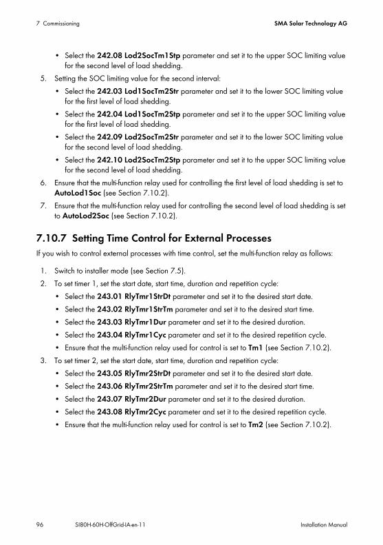
7 Commissioning SMA Solar Technology AG
96 SI80H-60H-OffGrid-IA-en-11 Installation Manual
• Select the 242.08 Lod2SocTm1Stp parameter and set it to the upper SOC limiting value for the second level of load shedding.
5. Setting the SOC limiting value for the second interval:• Select the 242.03 Lod1SocTm2Str parameter and set it to the lower SOC limiting value
for the first level of load shedding.• Select the 242.04 Lod1SocTm2Stp parameter and set it to the upper SOC limiting value
for the first level of load shedding.• Select the 242.09 Lod2SocTm2Str parameter and set it to the lower SOC limiting value
for the second level of load shedding.• Select the 242.10 Lod2SocTm2Stp parameter and set it to the upper SOC limiting value
for the second level of load shedding.6. Ensure that the multi-function relay used for controlling the first level of load shedding is set to
AutoLod1Soc (see Section 7.10.2).7. Ensure that the multi-function relay used for controlling the second level of load shedding is set
to AutoLod2Soc (see Section 7.10.2).
7.10.7 Setting Time Control for External ProcessesIf you wish to control external processes with time control, set the multi-function relay as follows:
1. Switch to installer mode (see Section 7.5).2. To set timer 1, set the start date, start time, duration and repetition cycle:
• Select the 243.01 RlyTmr1StrDt parameter and set it to the desired start date.• Select the 243.02 RlyTmr1StrTm parameter and set it to the desired start time.• Select the 243.03 RlyTmr1Dur parameter and set it to the desired duration.• Select the 243.04 RlyTmr1Cyc parameter and set it to the desired repetition cycle.• Ensure that the multi-function relay used for control is set to Tm1 (see Section 7.10.2).
3. To set timer 2, set the start date, start time, duration and repetition cycle:• Select the 243.05 RlyTmr2StrDt parameter and set it to the desired start date.• Select the 243.06 RlyTmr2StrTm parameter and set it to the desired start time.• Select the 243.07 RlyTmr2Dur parameter and set it to the desired duration.• Select the 243.08 RlyTmr2Cyc parameter and set it to the desired repetition cycle.• Ensure that the multi-function relay used for control is set to Tm2 (see Section 7.10.2).

SMA Solar Technology AG 7 Commissioning
Installation Manual SI80H-60H-OffGrid-IA-en-11 97
7.10.8 Setting the Control of the Battery-Room FanIf you wish to control a battery-room fan, set the multi-function relay as follows:
1. Switch to installer mode (see Section 7.5).2. Select the 221.04 BatFanTmpStr parameter and set it to the battery temperature at which the
fan is to be switched on.3. Ensure that the multi-function relay used for control is set to BatFan or MccBatFan
(see Section 7.10.2).4. Ensure that the battery room is sufficiently ventilated in the event of malfunctions – for example,
failure of the multi-function relay.
7.10.9 Setting Utilisation of Excess Energy
Figure 26: Switching-on time and switching-off time for utilisation of excess energy during float charge as a function of the cell voltage of the battery
The off-grid inverter controls the utilisation of excess energy during the constant voltage phase depending on the cell voltage of the battery. During the constant voltage phase, the battery is charged with a constant charging voltage. In the energy-saving mode, the multi-function relay is in the NC position. If the target value for cell voltage is reached in the constant voltage phase, the multi-function relay switches to the NO position. The multi-function relay stays in this position for the minimum time of 241.07 ExtPwrDerMinTm. If the cell voltage differs by more than the voltage difference of 241.08 ExtPwrDerDltVtg after the minimum time, the multi-function relay switches back to the NC position. The target value of the cell voltage depends on the charging process during the constant voltage phase.

7 Commissioning SMA Solar Technology AG
98 SI80H-60H-OffGrid-IA-en-11 Installation Manual
If you wish to control the utilisation of excess energy, set the multi-function relay as follows:
1. Switch to installer mode (see Section 7.5).2. Select the 241.07 ExtPwrDerMinTm parameter and set it to the minimum time that the
multi-function relay remains in the NO position.3. Select the 242.08 ExtPwrDerDltVtg parameter and set it to the voltage difference relative to
the target value of the cell voltage during float charge.
4. Ensure that the multi-function relay used for control is set to ExtPwrDer (see Section 7.10.2).
7.11 Changing the Battery Protection ModeFunction of the battery protection mode:Battery protection mode protects the battery.If the battery falls below the limiting values for the state of charge (SOC), the battery protection mode activates. In battery protection mode, the off-grid inverter switches to standby or automatically switches off. Battery protection mode has three levels. There is one SOC limiting value that can be set for each level. Levels 1 and 2 of battery protection mode are time-dependent with start and end times (see Section 7.7 "Setting Time-Dependent Functions", page 89).
• Level 1If the battery falls below the SOC limiting value for level 1, the off-grid inverter switches to standby between the start time and end time. In this way, you can specify times for which you prefer the stand-alone grid to be switched off if there is an energy deficit.
Charging process Parameter Default valueBoost charge 222.07 ChrgVtgBoost VRLA 2.40 V
FLA 2.55 VFull charge 222.08 ChrgVtgFul VRLA 2.40 V
FLA 2.50 VEqualisation charge 222.09 ChrgVtgEqu VRLA 2.40 V
FLA 2.50 V
Recording of the measured values of the cell voltage reacts to changes with time-lagThe off-grid inverter calculates the cell voltage from the measured battery voltage. The off-grid inverter calculates an average from the measured values of the battery voltage. As a result of the calculation of an average, the cell voltage that is recorded reacts to changes with time-lag.

SMA Solar Technology AG 7 Commissioning
Installation Manual SI80H-60H-OffGrid-IA-en-11 99
• Level 2If the battery falls below the SOC limiting value for level 2, the off-grid inverter switches to standby. The off-grid inverter tries to charge the battery during the day, when the PV inverters can supply energy.Using the start and end times, you set the time period during which the off-grid inverter starts to charge the battery every two hours. If there is no energy available to charge the battery, the off-grid inverter remains in standby.
• Level 3If the battery falls below the SOC limiting value for level 3, the off-grid inverter automatically switches off. This protects the battery against deep discharge and complete damage. To charge the battery again, the off-grid inverter must be manually switched on and started.
For all three levels, the off-grid inverter only switches to standby or switches off if no charging current flows into the battery within a period of 6 minutes.Recharging the battery with an external energy source:In levels 1 and 2 of battery protection mode, you can charge the battery at any time with an external energy source. If a voltage is present at the AC2 terminal, the off-grid inverter exits standby mode.If the off-grid inverter has switched itself off in level 3 of battery protection mode, you must charge the battery in emergency charge mode (see off-grid inverter operating manual).Time settings:The start time and the end time can be set for battery protection mode levels 1 and 2.If the battery falls below the SOC limiting value for level 1, the off-grid inverter switches to standby between the start time and end time.If the battery falls below the SOC limit for level 2, the off-grid inverter attempts to charge the battery between the end time and the start time of the battery. For the remaining time, the off-grid inverter stays on standby.Requirement: In a cluster, the Sunny Remote Control must be connected to the master.1. Switch to expert mode (see Section 7.6).2. To change battery protection mode 1, set the desired times and SOC limiting values:
• Select the 223.01 BatPro1TmStr parameter and set it to the desired start time.• Select the 223.02 BatPro1TmStp parameter and set it to the desired end time.• Select the 223.05 BatPro1Soc parameter and set it to the desired SOC limiting value.
3. To change battery protection mode 2, set the desired times and SOC limiting values:• Select the 223.03 BatPro2TmStr parameter and set it to the desired start time.• Select the 223.04 BatPro2TmStp parameter and set it to the desired end time.• Select the 223.06 BatPro2Soc parameter and set it to the desired SOC limiting value.
4. To change battery protection mode 3, select the 223.07 BatPro3Soc parameter and set it to the desired SOC limiting value.
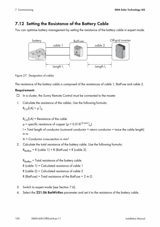
7 Commissioning SMA Solar Technology AG
100 SI80H-60H-OffGrid-IA-en-11 Installation Manual
7.12 Setting the Resistance of the Battery CableYou can optimise battery management by setting the resistance of the battery cable in expert mode.
Figure 27: Designation of cables
The resistance of the battery cable is composed of the resistances of cable 1, BatFuse and cable 2.Requirement: In a cluster, the Sunny Remote Control must be connected to the master.
1. Calculate the resistance of the cables. Use the following formula:RCU(l,A) = ρ l⁄A
RCU(l,A) = Resistance of the cableρ = specific resistance of copper (ρ = 0.018 Ω mm²⁄m)l = Total length of conductor (outward conductor + return conductor = twice the cable length) in mA = Conductor cross-section in mm²
2. Calculate the total resistance of the battery cable. Use the following formula:RBatRes = R (cable 1) + R (BatFuse) + R (cable 2)
RBatRes = Total resistance of the battery cableR (cable 1) = Calculated resistance of cable 1R (cable 2) = Calculated resistance of cable 2R (BatFuse) = Total resistance of the BatFuse = 2 m Ω
3. Switch to expert mode (see Section 7.6).4. Select the 221.06 BatWirRes parameter and set it to the resistance of the battery cable.
BatFusebattery Off-grid inverter
cable 1 cable 2
Length l1 Length l2

SMA Solar Technology AG 7 Commissioning
Installation Manual SI80H-60H-OffGrid-IA-en-11 101
7.13 Commissioning the Battery Current SensorTo operate the battery current sensor, you must set the type of the battery current sensor and start calibration and offset adjustment of the battery current sensor.The off-grid inverter distinguishes between 50 mV and 60 mV battery current sensors. These type designations indicate the amplification factor of the battery current sensor. The amplification factors are given in amperes per 50 mV or in amperes per 60 mV, e.g. 400 A/60 mV.If you have installed a battery current sensor, commission it as follows:Requirement: In a cluster, the Sunny Remote Control must be connected to the master.
1. Switch the off-grid system off and open the BatFuse switch-disconnector.2. Short-circuit the measuring cable on the battery
current sensor. Connect the BatCur– and BatCur+ measuring wires to the terminal for BatCur+.
3. Close the BatFuse switch-disconnector and switch the off-grid system on.4. Switch to installer mode (see Section 7.5).5. Select the 225.01 BatCurSnsTyp parameter and set it to the type of the battery current sensor
used.6. For a 60 mV model, select the 225.02 BatCurGain60 parameter and set it to the rated current
of the battery current sensor.7. For a 50 mV model, set the 225.03 BatCurGain50 parameter to the rated current of the
battery current sensor.8. Select the 225.04 BatCurAutoCal parameter and set it to Start.
The off-grid inverter starts calibration and offset adjustment.9. After ten seconds, select the 120.06 TotBatCur parameter and read off the value.
The parameter value is between 0 A and 1 A. The parameter value is not between 0 A and 1 A.
The measuring cables are not correctly connected or short-circuited.• Check whether the measuring cables are correctly connected and short-circuited.• Repeat steps 6 and 7.
10. Switch off the off-grid system and open the BatFuse switch-disconnector.

7 Commissioning SMA Solar Technology AG
102 SI80H-60H-OffGrid-IA-en-11 Installation Manual
11. Connect the BatCur+ measuring wire to the BatFuse L‒ side.
12. Connect the BatCur– measuring wire to the battery DC‒ side.
13. Close the BatFuse switch-disconnector and switch the off-grid system on.
7.14 Configuring the Limiting Values for the Generator Connection
7.14.1 Changing the Current Limiting Values for the GeneratorSignificance of the current limit:The generator management limits the consumption of generator current to the set maximum value.In three-phase off-grid systems, the generator current is limited for each line conductor individually. The set value thus applies for each phase.In off-grid inverters that are operated in parallel, the generator management only limits the total generator current. The generator current may be unequally distributed between the off-grid inverters. If an off-grid inverter fails, for example, more current will flow through the remaining off-grid inverters as a result. Each off-grid inverter limits its own current to the maximum output current at the AC2 terminal.Extended generator management:If the set generator current is not sufficient to supply the loads, the generator management requests additional current from the battery. The off-grid system then supplies the loads with generator current and battery current.
1. Switch to installer mode (see Section 7.5).2. Select the 234.03 GnCurNom parameter and set it to the desired value. Tip: A suitable value
for the 234.03 GnCurNom parameter is 80% of the maximum generator current per phase.

SMA Solar Technology AG 7 Commissioning
Installation Manual SI80H-60H-OffGrid-IA-en-11 103
7.14.2 Changing the Voltage Limiting Values for the GeneratorSignificance of the voltage limits:The voltage limiting values determine the range within which the generator voltage is allowed to fluctuate. When the off-grid inverter switches to the generator, the stand-alone grid will also fluctuate within this range.A breach of the set voltage limiting values leads to disconnection of the generator, to disconnection of the line conductor from the stand-alone grid or to the generator not being switched on.
1. Switch to expert mode (see Section 7.6).2. Select the 234.01 GnVtgMin parameter and set it to the minimum generator voltage.3. Select the 234.02 GnVtgMax parameter and set it to the maximum generator voltage.
7.14.3 Changing the Frequency Limiting Values of the Generator Voltage
Significance of the frequency limits:The frequency limiting values determine the range within which the frequency of the generator voltage is allowed to fluctuate. When the off-grid inverter switches to the generator, the stand-alone grid will also fluctuate within this range.A breach of the set frequency limiting values leads to disconnection of the generator, to disconnection of the line conductor from the stand-alone grid or to the generator not being switched on.
1. Switch to expert mode (see Section 7.6).2. Select the 234.04 GnFrqNom parameter and set it to the rated frequency of the generator
voltage.3. Select the 234.05 GnFrqMin parameter and set it to the minimum frequency of the generator
voltage.4. Select the 234.06 GnFrqMax parameter and set it to the maximum frequency of the generator
voltage.

7 Commissioning SMA Solar Technology AG
104 SI80H-60H-OffGrid-IA-en-11 Installation Manual
7.14.4 Changing the Permitted Reverse Power to the GeneratorIf the reverse power for the set time is exceeded, all off-grid inverters disconnect the generator from the stand-alone grid and block connection of the generator to the stand-alone grid for the minimum stop time.
1. Switch to expert mode (see Section 7.6).2. Select the 234.13 GnRvPwr parameter and set it to the active power of the generator reverse
power.3. Select the 234.14 GnRvTm parameter and set it to the time for the generator reverse power.
7.14.5 Setting the Current Limit for the Generator Depending on the Frequency
Interdependency of frequency and current limit:The higher the generator current, the higher the torque for the generator. The speed drops with increasing torque for unregulated generators. When the torque drops, the frequency of the generator voltage is also reduced.If the frequency of the generator voltage falls below the rated frequency, the generator management can also limit the generator current. The lower the frequency, the more the generator current is limited by generator management. This setting is useful if the generator is supplying other loads in parallel with the off-grid inverter. This setting allows the maximum load to be placed on the generator without overloading it.Requirement: The generator must not be an inverter generator. The output frequency of inverter generators is
fixed.
1. Switch to expert mode (see Section 7.6).2. Select the 234.03 GnCurNom parameter and set it to the desired value. Tip: A suitable value
for the 234.03 GnCurNom parameter is 80% of the maximum generator current per phase.3. Select the 234.15 GnCtlMod parameter and set it to CurFrq. In this way, you will activate the
frequency-dependent current limitation.
Damage to the generatorIn case of reverse power, the AC sources in the stand-alone grid drive the generator. The generator can be damaged as a result.
• Observe the information from the manufacturer about reverse power protection of the generator.
• Set the generator reverse power and the permitted time for reverse power in accordance with the manufacturer's specifications.

SMA Solar Technology AG 7 Commissioning
Installation Manual SI80H-60H-OffGrid-IA-en-11 105
7.15 Changing the Type of Generator InterfaceIf you have installed a generator in an off-grid system, the type of generator interface determines the way the generator is controlled.
1. Switch to installer mode (see Section 7.5).2. If the generator has an autostart function, select the 234.07 GnStrMod parameter and set it
to Autostart.3. If the generator does not have an autostart function, select the 234.07 GnStrMod parameter
and set it to Manual.4. If the generator is controlled using GenMan, select the 234.07 GnStrMod parameter and set
it to GenMan.
7.16 Configuring Generator Run Times
7.16.1 Changing the Warm-Up Time for the GeneratorInterrelationship between warm-up time and abortion of generator start:Generator management measures the time between the generator start and the beginning of the warm-up time. If a maximum time is exceeded, generator management aborts the generator start. The maximum time to start termination depends on the generator interface:
• If the 234.07 GnStrMod parameter is set to Autostart or Manual, the maximum time to start abortion is double the warm-up time plus an additional two minutes.
• If the parameter 234.07 GnStrMod is set to GenMan, the maximum time to start abortion is ten minutes.
For certain generator types, the generator only switches the voltage to the generator output after the internal warm-up time has finished. During this time, the generator management cannot detect any valid generator voltage. If the warm-up time is set too low, the generator management aborts the generator start before the internal warm-up time of the generator has ended.
1. Switch to installer mode (see Section 7.5).2. For generators without internal warm-up time:
• Select the 234.12 GnWarmTm parameter and set it to the desired warm-up time.3. For generators with an internal warm-up time:
• For generators with an autostart function, select the 234.12 GnWarmTm parameter and set the warm-up time to be at least half the internal warm-up time of the generator.
• For generators without an autostart function, select the 234.12 GnWarmTm parameter and set the warm-up time to be at least half the internal warm-up time of the generator.
• For generators with GenMan, select the 234.12 GnWarmTm parameter and set the warm-up time to be at least six minutes.
The generator start is not aborted prematurely.

7 Commissioning SMA Solar Technology AG
106 SI80H-60H-OffGrid-IA-en-11 Installation Manual
7.16.2 Changing the Minimum Run Time for the Generator1. Switch to installer mode (see Section 7.5).2. Select the 234.08 GnOpTmMin parameter and set it to the desired value.
7.16.3 Changing the Shut-Off Delay Time for the Generator
1. Switch to installer mode (see Section 7.5).2. Select the 234.10 GnCoolTm parameter and set it to the desired value.
7.16.4 Changing the Minimum Stop Time for the Generator1. Switch to installer mode (see Section 7.5).2. Select the 234.09 GnStpTmMin parameter and set it to the desired value.
7.17 Configuring the Generator Request
7.17.1 Changing the Automatic Generator ModeSignificance of Automatic Generator Mode:In automatic generator mode, generator management specifies when and for how long the generator will run, depending on the configuration.
1. Switch to installer mode (see Section 7.5).2. To deactivate automatic generator mode, select the 235.01 GnAutoEna parameter and set it
to Disable.3. To activate automatic generator mode, select the 235.01 GnAutoEna parameter and set it to
Enable.
GenMan shut-off delay timeGenMan has its own shut-off delay.
• Set the shut-off delay time to be the same as or greater than the shut-off delay time of the GenMan.
Internal shut-off delay of the generatorGenerators can have an internal shut-off delay that is activated only when generator request has been disabled. Note that this internal shut-off delay increases the actual shut-off delay.

SMA Solar Technology AG 7 Commissioning
Installation Manual SI80H-60H-OffGrid-IA-en-11 107
7.17.2 Changing the State-Of-Charge-Dependent Generator Request
Significance of the SOC limiting values:If the battery reaches the lower SOC limiting value, the generator management requests the generator. If the battery reaches the upper SOC limiting value during recharging, generator management resets this generator request.
1. Switch to installer mode (see Section 7.5).2. Select the 235.03 GnSocTm1Str parameter and set it to the lower SOC limiting value.3. Select the 235.04 GnSocTm1Stp parameter and set it to the upper SOC limiting value.4. Set the 235.07 GnTm1Str and 235.08 GnTm2Str parameters to the same value, e.g. both
to 000000. This deactivates the time-dependent generator request.
7.17.3 Setting Time-Dependent Generator RequestSignificance of the start times and SOC limiting values:The time-dependent generator request divides the day into two intervals. For each interval, you set the conditions that apply for generator request (see Section 7.7 "Setting Time-Dependent Functions", page 89). For example, you set the generator not to start at night. This ensures that the noise pollution caused by the generator takes place during the day where possible.Both intervals have a lower and an upper SOC limiting value each. If the battery reaches the lower SOC limiting value, the generator management requests the generator. When the battery reaches the upper SOC limiting value during recharging, generator management resets this generator request. The following settings are possible for the SOC limiting values:
• The lower SOC limiting value is smaller than the upper SOC limiting value.The generator is requested during this interval depending on the state of charge.
• The lower SOC limiting value is greater than or equal to the upper SOC limiting value.The generator is not started depending on the state of charge. In this interval the other settings for generator requests apply – e.g. load-dependent generator request.

7 Commissioning SMA Solar Technology AG
108 SI80H-60H-OffGrid-IA-en-11 Installation Manual
1. Switch to installer mode (see Section 7.5).2. Select the 235.07 GnTm1Str parameter and set it to the start time for the first interval.3. Select the 235.03 GnSocTm1Str parameter and set it to the lower SOC limiting value during
the first interval.4. Select the 235.04 GnSocTm1Stp parameter and set it to the upper SOC limiting value during
the first interval.5. Select the 235.08 GnTm2Str parameter and set it to the start time for the second interval.6. Select the 235.05 GnSocTm2Str parameter and set it to the lower SOC limiting value during
the second interval.7. Select the 235.06 GnSocTm2Stp parameter and set it to the upper SOC limiting value during
the second interval.
Example: from 10:00 p.m. to 6:00 a.m., the generator is not to start where possible.
Figure 28: Profile of the SOC and the times for generator requests
The start time for the first interval is set to 6:00 a.m. In the first interval, the lower SOC limiting value is set to 40% and the upper SOC limiting value is set to 80%.The start time for the second interval is set to 10:00 p.m. In the second interval, the lower SOC limiting value is set to 30% and the upper SOC limiting value is set to 40%.

SMA Solar Technology AG 7 Commissioning
Installation Manual SI80H-60H-OffGrid-IA-en-11 109
7.17.4 Setting Load-Dependent Generator RequestSignificance of load-dependent generator request:If you activate the load-dependent generator request, the off-grid inverter requests the generator in the event of a high load. This prevents deep discharge and cycling of the battery and extends its electrical endurance. The output power of the off-grid system for supplying the loads increases to the total of the generator power and the power of the off-grid inverter. This improves the system stability. The load is the calculated average output power of the off-grid inverter.Loads in the three-phase off-grid system:The generator management considers the total load of all line conductors. It does not monitor individual line conductors in the three-phase off-grid system. If the switch-on power limit is exceeded for one line conductor, the generator management requests the generator.Time sequence of load-dependent generator request:If the switch-on power limit is reached, the generator management requests the generator. If the load then reduces to the switch-off power limit, generator management resets the generator request after the minimum run time. Generator management calculates the average load during the averaging time 235.12 GnPwrAvgTm. The greater the averaging time that you set, the less generator management reacts to load peaks.Generator run times:The warm-up, minimum and shut-off delay times are adhered to after the generator start. The power from the generator is not immediately available in the stand-alone grid. Each start also means that the generator runs for at least the warm-up time, minimum run time and shut-off delay time.
1. Switch to expert mode (see Section 7.6).2. Select the 235.09 GnPwrEna parameter and set it to Enable. This activates load-dependent
generator request.3. Select the 235.10 GnPwrStr parameter and set it to the switch-on power limit.4. Select the 235.11 GnPwrStp parameter and set it to the switch-off power limit.5. Select the 235.12 GnPwrAvgTm parameter and set it to the averaging time that the generator
management uses to calculate the average power.

7 Commissioning SMA Solar Technology AG
110 SI80H-60H-OffGrid-IA-en-11 Installation Manual
7.17.5 Time-Controlled Activation of the GeneratorWhen the generator is requested in a time-controlled manner, it is requested on certain days for a set duration (see Section 7.8 "Setting the Time-Controlled Functions", page 89).
1. Select the 235.13 GnTmOpEna parameter and set it to Enable.2. Select the 235.14 GnTmOpStrDt parameter and set it to the desired start date.3. Select the 235.15 GnTmOpStrTm parameter and set it to the desired start time.4. Select the 235.16 GnTmOpRnDur parameter and set it to the desired duration.5. Select the 235.17 GnTmOpCyc parameter and set it to the desired repetition cycle:
7.17.6 Changing the Generator Request Depending on the Charging Process of the Battery
1. Switch to expert mode (see Section 7.5).2. To activate the generator for equalisation charge, select the 235.18 GnStrChrgMod
parameter and set it to Equal.3. To request the generator in the event of full charge, select the 235.18 GnStrChrgMod
parameter and set it to Full.4. To request the generator in the event of equalisation charge and full charge, select the
235.18 GnStrChrgMod parameter and set it to Both.5. To deactivate generator request depending on the charging process of the battery, select the
235.18 GnStrChrgMod parameter and set it to Off.
Value ExplanationSingle Single generator request on the start dateDaily Daily generator request starting on the start dateWeekly Weekly generator request starting on the start date
The start date determines the weekday.

SMA Solar Technology AG 7 Commissioning
Installation Manual SI80H-60H-OffGrid-IA-en-11 111
7.17.7 Setting the External Generator RequestSignificance of external generator request:An external control signal can transfer a generator request to the generator management.
1. Switch to expert mode (see Section 7.5).2. To activate external generator request, select the 235.19 GnStrDigIn parameter and set it to
Enable.3. To deactivate external generator request, select the 235.19 GnStrDigIn parameter and set it
to Disable.
7.18 Setting the Procedure in the Event of an Aborted Start of the Generator
Operating procedure if an aborted strat of the generator is detected:If the off-grid inverter detects a generator false start (e.g. voltage too high), the off-grid inverter does not switch the stand-alone grid to the generator.If there is another request for the generator after the minimum stop time, the off-grid inverter attempts to start the generator.If the off-grid inverter detects a false start on a number of occasions and the number of failed attempts exceeds the maximum value, the off-grid inverter switches to error mode.After the set time has elapsed, the off-grid inverter attempts to restart the generator.Single-cluster systems:Generator management evaluates a fault in the line conductor on the master as a failure of the generator. All off-grid inverters disconnect the stand-alone grid from the generator.Generator management treats a fault in the line conductor of the slave as a line conductor fault. The slave only disconnects the affected line conductor from the stand-alone grid. The slave switches the stand-alone grid to the generator again when the faulty line conductor is in the valid range.
1. Switch to expert mode (see Section 7.6).2. To change the maximum number of failed attempts:
• Select the 235.01 GnAutoEna parameter and set it to Enable.• Select the 235.02 GnAutoStr parameter and set it to the desired number of start attempts.
3. To change the stop time of the generator after the maximum number of start attempts has been exceeded, select the 234.11 GnErrStpTm parameter and set it to the desired stop time.

7 Commissioning SMA Solar Technology AG
112 SI80H-60H-OffGrid-IA-en-11 Installation Manual
7.19 Changing the Current Limiting Values for the Electricity GridSignificance of the current limit:Grid management limits the consumption of line current to the set maximum value.Advanced grid management:If the set line current is not sufficient for supplying the loads, grid management requests additional power from the battery. The off-grid inverter then feeds additional power from the battery into the stand-alone grid.
1. Switch to installer mode (see Section 7.5).2. Select the 232.03 GdCurNom parameter and set it to the maximum line current.
7.20 Changing the Sleep ModeSleep mode makes it possible to save energy in single-phase parallel off-grid systems.If the power of the loads does not require the power of all off-grid inverters, the master switches off one or two slaves. The power thresholds at which the slaves are switched off and on have been optimised at the factory. You cannot change the power threshold.
1. Switch to installer mode (see Section 7.5).2. To deactivate sleep mode, select the 250.10 SleepEna parameter and set it to Disable.3. To activate sleep mode, select the 250.10 SleepEna parameter and set it to Enable.4. To activate sleep mode in a time-controlled manner, activate overnight shutdown and change
the times:• Select the 250.10 SleepEna parameter and set it to Enable.• Select the 250.13 SleepAtNight parameter and set it to Enable.• Select the 250.14 SlpStrTm parameter and set it to the start time.• Select the 250.15 SlpStpTm parameter and set it to the stop time.

SMA Solar Technology AG 7 Commissioning
Installation Manual SI80H-60H-OffGrid-IA-en-11 113
7.21 Setting the Search ModeSearch mode makes it possible to save energy.At regular intervals, the off-grid inverter checks whether loads are connected to the off-grid system. If the off-grid inverter does not detect any loads, it switches to energy-saving mode. As soon as a load is connected, the off-grid inverter exits energy-saving mode and switches to inverter operation.
Requirement: For single-phase parallel systems, sleep mode must be activated.
1. Switch to installer mode (see Section 7.5).2. Select the 250.31 SearchMod parameter and set it to the desired value:
3. Switch to expert mode (see Section 7.6) to change the sensitivity of the detection of loads or to control the search mode in a time-controlled manner.
4. To change the sensitivity, select the 250.32 SearchModSns parameter and set it to the desired value:
5. To operate search mode in a time-controlled manner, change the start time and stop time:• Select the 250.33 SearchModStr parameter and set it to the start time.• Select the 250.34 SearchModStp parameter and set it to the stop time.
7.22 Setting the Silent ModeSilent mode makes it possible to save energy in backup systems.
Detection of loads in a three-phase systemIn a three-phase system, each off-grid inverter automatically activates energy-saving mode independently for each line conductor. In a three-phase system, the off-grid inverter does not identify loads as loads when they are connected using delta connections.
Value ExplanationDisable Search mode is deactivated.Enable Search mode is activated with no interruptions.Timed Search mode is activated only in the set time interval.
Value ExplanationVery High Highest sensitivityHigh High sensitivity, P < 15 WMiddle Middle sensitivity, P < 20 WLow Low sensitivity, P < 30 WVery Low Lowest sensitivity, P < 50 W

7 Commissioning SMA Solar Technology AG
114 SI80H-60H-OffGrid-IA-en-11 Installation Manual
If a set time for float charge has elapsed, the off-grid inverter switches to silent mode and the stand-alone grid is supplied only by the electricity grid and the AC sources in the stand-alone grid. The off-grid inverter exits idle mode at configurable time intervals or else when the battery voltage per cell drops by 0.14 V. As a result, the battery always remains fully charged. If the electricity grid fails in energy-saving mode, the off-grid inverter makes a stand-alone grid available for use within seconds.
1. Switch to expert mode (see Section 7.6).2. To activate silent mode, set the values of the following parameters:
• Select the 224.01 SilentEna parameter and set it to Enable.• Select the 224.02 SilentTmFlo parameter and set it to the maximum time for float charge.• Select the 224.03 SilentTmMax parameter and set it to the maximum duration for energy-
saving mode.3. To deactivate silent mode, select the 224.01 SilentEna parameter and set it to Disable.
7.23 Changing the Automatic Frequency SynchronisationAutomatic frequency synchronisation allows for the use of timepieces using the power frequency as a timer. In this way, the power frequency dictates the accuracy of the timepiece. In the case of power frequencies with ongoing frequency deviations from the rated frequency, the time indications will become increasingly inaccurate.Ongoing frequency deviations occur in off-grid systems with PV inverters and generators, for example. If the automatic frequency synchronisation is activated, the off-grid inverter regulates the frequency deviations during the day.The timepiece in the off-grid inverter is quartz-controlled and is not dependent on the power frequency.
1. Switch to expert mode (see Section 7.6).2. To deactivate automatic frequency synchronisation, select the 250.11 AfraEna parameter and
set it to Disable.3. To activate automatic frequency synchronisation, select the 250.11 AfraEna parameter and
set it to Enable.

SMA Solar Technology AG 7 Commissioning
Installation Manual SI80H-60H-OffGrid-IA-en-11 115
7.24 Functional Test
7.24.1 Testing Communication InterfacesIf communication interfaces are installed in the off-grid inverter, test that they have been installed correctly as follows:
1. Switch to installer mode (see Section 7.5).2. To test the installation of the SI-SYSCAN.BGx Multicluster communication interface, select the
312.15 ComMod1 parameter and read off the value. The value is SI-SysCan. Is the value ‒‒‒?
The communication interface is not plugged into the interface slot correctly.• Ensure that the communication interface is plugged into the SISysCan interface slot.• Ensure that the communication interface has been installed correctly
(see the SI-SYSCAN-NR mounting instructions).3. To test the installation of the RS485 SI-COMSMA.BGx communication interface, select the
312.16 ComMod2 parameter and read off the value. The value is SI-ComSma. Is the value ‒‒‒?
The communication interface is not plugged into the interface slot correctly (see the mounting instructions for the communication interface).• Ensure that the communication interface is plugged into the SiComSma interface slot.• Ensure that the communication interface has been installed correctly
(see the SI-COMSMA-NR mounting instructions).

7 Commissioning SMA Solar Technology AG
116 SI80H-60H-OffGrid-IA-en-11 Installation Manual
7.24.2 Starting the Off-Grid SystemRequirement: All off-grid inverters must be switched on.
1. If no functional test has been completed yet, switch off all miniature circuit-breakers and switch-disconnectors for the AC sources in the sub-distributions.
2. Press the start-stop button on the off-grid inverter and hold it until you hear a signal.orPress and hold the button on the Sunny Remote Control until you hear a signal.
The inverter LED is glowing green on every off-grid inverter.
7.24.3 Testing the Battery Current SensorIf a battery current sensor is present, you must carry out the following steps.Requirement: All miniature circuit-breakers in the AC sub-distribution must be switched off.
1. Connect the miniature circuit-breaker of one load in the AC sub-distribution.2. Measure the battery current with a current clamp.3. Switch to installer mode (see Section 7.5).4. Select the 120.06 TotBatCur parameter and read off the value.
The value is positive and corresponds to the measured value. Is the value not positive or does it not correspond to the measured value?
The value is negative because the poles of the measuring cables of the battery current sensor are reversed.• Install the battery current sensor correctly (see section 6.29).The value does not correspond to the measured value because the incorrect battery current sensor type has been set.• Set the correct battery current sensor type (see Section 7.13 "Commissioning the Battery
Current Sensor", page 101).

SMA Solar Technology AG 7 Commissioning
Installation Manual SI80H-60H-OffGrid-IA-en-11 117
7.24.4 Testing the GeneratorIf a generator is present, you must carry out the following steps:Requirements: The miniature circuit-breakers for the AC sources must be switched off in the AC sub-distribution. The miniature circuit-breakers for DC sources must be switched off in the DC sub-distribution. The off-grid inverter must be in operation (see Section 7.24.2 "Starting the Off-Grid
System", page 116).
1. Connect the miniature circuit-breakers in the sub-distribution for external energy sources.2. Connect the miniature circuit-breakers of the AC loads in the AC sub-distribution.3. Connect the loads.
The generator starts or the generator request is shown. Does the generator not start?
Generator management does not request the generator.• Manually start the generator with the Sunny Remote Control (see the operating manual
of the off-grid inverter).The generator or signal generator is not being activated.• Rectify any faults in the wiring.The generator is not operational.• Identify possible causes using the manufacturer's manual and rectify these.
4. Switch to installer mode (see Section 7.5).5. Select the 133.02 GnStt parameter and wait until the Run parameter is shown. In this way,
you will know that the off-grid inverter has connected the stand-alone grid to the generator. Is the grid LED glowing red?
The off-grid inverter does not switch the stand-alone grid to the generator due to an error message.• Select the 410# Error active menu and rectify the cause of the displayed warning or
error.6. For single systems and single-cluster systems, check whether the connected active power of the
loads corresponds to the value of the 111.05 TotLodPwr parameter.If the power shown is too high, rectify the defective load or fault in the wiring.
7. For multicluster systems, check whether the value of the 111.06 TotMccLodPwr parameter corresponds to the connected active power of the loads.If the power shown is too high, rectify the defective load or fault in the wiring.
8. Stop the generator (see the operating manual for the off-grid inverter).

7 Commissioning SMA Solar Technology AG
118 SI80H-60H-OffGrid-IA-en-11 Installation Manual
7.24.5 Testing Load SheddingIf load shedding is present, you must carry out the following steps:Requirements: All miniature circuit-breakers in all sub-distributions must be switched off. All loads must be switched off. The off-grid inverter must be in operation (see Section 7.24.2 "Starting the Off-Grid
System", page 116).
1. Switch to installer mode (see Section 7.5).2. Note the set limiting values for load shedding:
• Select the 242.01 Lod1SocTm1Str parameter and note its value.• Select the 242.03 Lod1SocTm2Str parameter and note its value.• Select the 242.07 Lod2SocTm1Str parameter and note its value.• Select the 242.09 Lod2SocTm2Str parameter and note its value.
3. Connect the miniature circuit-breakers of the AC loads in the sub-distribution. This discharges the battery. The battery cannot be recharged because all sources are switched off.
4. Connect the loads and wait until the load-shedding contactor discards the loads. Tip: Select the 120.01 BatSoc parameter and compare the state of charge with the configured limit for load shedding. You can then check when the load-shedding contactor should discard the loads. The load-shedding contactor discards the loads. Does the load-shedding contactor not discard the loads?
The multi-function relay for activating the load-shedding contactor is incorrectly configured.• Check the configuration and rectify the fault.There is a fault in the wiring of the load-shedding contactor.• Select the parameter of the multi-function relay for the load-shedding contactor,
e.g. 241.02 Rly2Op for the Relay 2 multi-function relay of the master.• Note the setting.• Alternately set the parameter to On or Off. In this way, you can isolate the fault.• Rectify the fault.• Set the parameter to the setting that has been noted.
5. Switch off the loads and the miniature circuit-breakers of the AC loads in the sub-distribution.

SMA Solar Technology AG 7 Commissioning
Installation Manual SI80H-60H-OffGrid-IA-en-11 119
7.24.6 Testing the Frequency Shift Power ControlRequirements: All AC loads must be switched off. The miniature circuit-breakers for the external energy source must be switched off. The off-grid inverter must be in operation (see Section 7.24.2 "Starting the Off-Grid
System", page 116). The PV inverters or the wind power inverters must be feeding current into the stand-alone grid.
1. Switch to installer mode (see Section 7.5).2. Select the 120.06 TotBatCur parameter and note the value. You will then know the present
battery charging current.3. Select the limit for the charging current of the battery, 222.01 BatChrgCurMax, and note the
value. You can then undo the following changes.4. Set the limit for the charging current of the battery, 222.01 BatChrgCurMax to a current that
is significantly lower than the charging current of the battery 120.06 TotBatCur.5. Check whether the stand-alone grid frequency, 112.05 InvFrq, is 1 Hz to 2 Hz higher than the
rated frequency of the stand-alone grid.If the stand-alone grid frequency increases by less than 1 Hz, not all PV inverters and wind power inverters are configured for stand-alone grid operation. Set the PV inverters and wind power inverters to stand-alone grid operation (see the manuals of the PV inverters and wind power inverters).
6. Select the 222.01 BatChrgCurMax parameter and set it to the limit noted in step 3.
7.25 Charging the Battery1. Ensure that the wiring has been checked (see Section 7.2).2. Ensure that the functional test has been carried out (see Section 7.24).3. Connect or close the miniature circuit-breakers and fuse-switch-disconnectors for energy
sources.4. Disconnect or open all loads, the miniature circuit-breakers of the loads and the fuse-switch-
disconnectors. As a result, only the energy sources will be connected to the off-grid inverter.5. Start the off-grid system (see Section 7.24.2). The off-grid inverter starts charging the battery automatically.

7 Commissioning SMA Solar Technology AG
120 SI80H-60H-OffGrid-IA-en-11 Installation Manual
7.26 Completing Commissioning• When full charge is complete, switch on all miniature circuit-breakers and switch-disconnectors.
Tip: The state of charge of the battery is displayed in standard mode.
Load shedding in the first two operating hoursThe state of charge (SOC) recorded by battery management and the available battery capacity (SOH) will deviate strongly from the actual values of SOC and SOH for a newly connected battery. During operation, the values recorded by battery management will gradually approach the real values. In the first two hours of operation with the new battery, these deviations can lead to load shedding and corresponding entries in the 400# Failure/Event menu.

SMA Solar Technology AG 8 Decommissioning
Installation Manual SI80H-60H-OffGrid-IA-en-11 121
8 Decommissioning8.1 Disconnecting the Off-Grid Inverter from Voltage Sources1. Disconnect the off-grid system (see the operating manual of the off-grid inverter).2. Open the switch-disconnector of the BatFuse and secure it against reconnection (see the manual
of the BatFuse).3. Disconnect the miniature circuit-breakers and fuse-switch-disconnectors in the sub-distributions
and secure them against reconnection.
5. Unscrew all screws of the enclosure lid and remove the enclosure lid.6. Ensure that the DC connection is disconnected from voltage sources.7. Ensure that the terminals AC1 Loads/SunnyBoys and AC2 Gen/Grid are disconnected from
voltage sources.8. Earth and short-circuit the AC conductors.9. Cover or safeguard any adjacent live components.
8.2 Disassembling the Off-Grid Inverter1. Disconnect the off-grid inverter from voltage sources (see Section 8.1).2. Remove all cables from the off-grid inverter.3. Close the off-grid inverter (see Section 7.3).4. Remove the ventilation grids sideways.
4.Damage to the off-grid inverter due to electrostatic dischargeBy touching electronic components, you can damage or destroy the off-grid inverter.
• Earth yourself before touching any components.

8 Decommissioning SMA Solar Technology AG
122 SI80H-60H-OffGrid-IA-en-11 Installation Manual
5. If the off-grid inverter is protected against theft, loosen the safety screws.
6. Loosen the screws between the off-grid inverter and the wall mounting bracket on both sides using an Allen key (AF 5).
7.Risk of injury due to the heavy weight of the off-grid inverter
• Take into account the weight of the off-grid inverter (see Section 12 "Technical Data", page 144).
• Lift the off-grid inverter upwards and off the wall mounting bracket. To do this, use the side recess grips or a steel rod (diameter: maximum 30 mm). Keep the off-grid inverter horizontal when moving it.

SMA Solar Technology AG 8 Decommissioning
Installation Manual SI80H-60H-OffGrid-IA-en-11 123
8.3 Packing the Off-Grid Inverter1. Remove the cable glands from the off-grid inverter.2. Pack the off-grid inverter and the cable glands. Use original packaging or packaging that is
suitable for the weight and dimensions of the off-grid inverter (see Section 12 "Technical Data", page 144).
8.4 Disposal of the Off-Grid Inverter• Dispose of the off-grid inverter in accordance with the locally applicable disposal regulations
for electronic waste.or
• Return the off-grid inverter to SMA Solar Technology AG at your own expense (see Section 13 "Contact", page 154). Label the packaging "ZUR ENTSORGUNG" ("FOR DISPOSAL").

9 Battery Management SMA Solar Technology AG
124 SI80H-60H-OffGrid-IA-en-11 Installation Manual
9 Battery Management9.1 State of the Battery
9.1.1 Available Battery CapacityThe available capacity of a new battery is equal to the rated capacity specified by the battery manufacturer. During operation of an off-grid system, the available battery capacity decreases for the following reasons:
• Increasing age of the battery• Frequent, insufficient charging• Temperatures below the rated temperature
Currently available battery capacity:Battery management reports the currently available battery capacity as a percentage of the rated capacity (SOH). After initial start-up of the off-grid system, battery management requires a few charging cycles before it can measure the currently available battery capacity with sufficient accuracy. For this reason, battery management initially uses the rated capacity specified in the QCG.Automatic correction of the currently available battery capacity:The available capacity of a battery falls significantly at temperatures of 20°C and below. Battery management corrects the currently available battery capacity by –1% per °C.
9.1.2 Current State of ChargeBattery management reports the current state of charge (SOC) of the battery.Estimated error of the state of charge:The estimated error of the state of charge provides information concerning the accuracy of the current calculation of the state of charge of the battery. The deviation between the displayed state of charge and the actual value decreases with every charging procedure.
9.1.3 Battery TemperatureBattery management continuously monitors the battery temperature. The off-grid inverter adjusts the reported currently available battery capacity and the charging voltage based on the current operating battery temperature (see Section 9.2.3 "Automatic Temperature Compensation", page 128).Battery management issues a warning message if one of the following events occurs:
• The battery temperature is within 5°C of the maximum permissible battery temperature.• The battery temperature is less than − 10°C.

SMA Solar Technology AG 9 Battery Management
Installation Manual SI80H-60H-OffGrid-IA-en-11 125
If the maximum permitted battery temperature is exceeded, the off-grid inverter switches off. Once the battery has cooled down to a specified temperature, the off-grid inverter starts again.
9.2 Charge Control
9.2.1 Charging Phases
Figure 29: Charging phases of the off-grid inverterThe off-grid inverter controls battery charging in three phases, as follows:
• Constant current phase (I phase/bulk phase)• Constant voltage phase (absorption phase/Uo)• Float charge
There is also the idle phase in the case of electricity grid operation with activated silent mode.
Constant Current PhaseThe aim of the constant voltage phase is to reach the full battery voltage.In the constant current phase, battery management initially increases the current until one of the following values has been reached:
• Maximum charge current of battery• Rated current of the external energy source• Maximum AC charge current of the off-grid inverter

9 Battery Management SMA Solar Technology AG
126 SI80H-60H-OffGrid-IA-en-11 Installation Manual
The first value reached limits the charge current of the battery. While the charge current remains constant, the battery voltage increases with increasing state of charge. The constant current phase ends when the cell voltage of the battery reaches the target value specified for the relevant battery type.
Constant Voltage PhaseIn the constant voltage phase, battery management attempts to charge the battery fully. In this phase, the battery voltage remains constant while the battery current slowly reduces. For the constant voltage phase, battery management chooses one of the following three charging processes:
• Boost charge• Full charge• Equalisation charge
The off-grid inverter has a specified time for each charging process: Once this time has elapsed, the constant voltage phase ends. The off-grid inverter switches to float charge.
Float ChargeThe purpose of float charge is to maintain the battery in a fully charged state without overloading the battery. At the beginning of float charge, battery management reduces the charging voltage in steps until the target value specified for float charge has been achieved. Battery management then maintains this charging voltage until the end of float charge. Float charge ends when one of the following conditions is met:
• The total of all electric discharges of the battery has reached 30% of the rated capacity.• The current state of charge is less than 70% of the available charging capacity.
Battery management switches from float charge to the constant current phase. If the stand-alone grid is connected to the electricity grid, battery management can also switch from float charge to energy-saving mode.
Energy-Saving ModeIn energy-saving mode, the off-grid inverter switches to standby, thus saving energy.If a set time for float charging has elapsed for grid backup systems, battery management switches to energy-saving mode and the stand-alone grid is supplied only by the electricity grid and the AC sources in the stand-alone grid. The off-grid inverter exits energy-saving mode at configurable time intervals or when the battery voltage per cell drops by 0.14 V (see Section 7.22 "Setting the Silent Mode", page 113). In this way, the battery always remains fully charged. If the electricity grid fails in energy-saving mode, the off-grid inverter provides a stand-alone grid within seconds.

SMA Solar Technology AG 9 Battery Management
Installation Manual SI80H-60H-OffGrid-IA-en-11 127
9.2.2 Charging ProcessesFor transition to the constant voltage phase, battery management chooses one of the following three charging processes:
• Boost charge• Full charge• Equalisation charge
Boost chargeFor boost charge, a high charging voltage is applied to the battery. The battery is charged to 85% to 90% of the currently available battery capacity within a short period of time.Boost charge allows for a high degree of utilisation of the generator and leads to gassing of the FLA batteries, which in turn leads to equalisation of the electrolyte.
Full chargeThe aim of full charge is to charge the battery to a state of charge of at least 95%. This should compensate for effects caused by any insufficient charging and should also increase the service life of the battery.The off-grid inverter carries out full charging of the battery if one of the following conditions is met:
• The specified cycle time for full charge has elapsed (e.g. every 14 days).• The total of all electric discharges since the last full charging corresponds to eight times the rated
capacity of the battery.
Equalisation ChargeWith equalisation charge, the off-grid inverter neutralises differences in the states of charge of individual battery cells that have resulted from the differing behaviour of various battery cells. In this way, the off-grid inverter prevents the premature failure of individual battery cells and increases the service life of the battery.The off-grid inverter carries out an equalisation charge of the battery if the automatic equalisation charge is activated and one of the following conditions is met:
• The specified cycle time for equalisation charge has elapsed (e.g. every 30 days).• The total of all electric discharges since the last equalisation charge corresponds to 30 times the
rated capacity of the battery.
External charging deviceAn external charging device or a charge controller can also carry out full charge of the battery. The Sunny Island treats this full charge as equivalent to a full charge that it carries out itself.

9 Battery Management SMA Solar Technology AG
128 SI80H-60H-OffGrid-IA-en-11 Installation Manual
To protect or maintain the battery on off-grid systems that are used seasonally, you can start equalisation charge manually (see the operating manual of the off-grid inverter).
9.2.3 Automatic Temperature CompensationThe charging capability of the battery is dependent on temperature. To prevent overcharging and insufficient charging of the battery, battery management has an automatic temperature compensation function.For temperatures over 20°C, battery management increases the charging voltage. For temperatures under 20°C, battery management reduces the charging voltage.
External charging deviceAn external charging device or a charge controller can also carry out equalisation charge of the battery.The off-grid inverter treats equalisation charge by an external charge controller as equivalent to a equalisation charge that it carries out itself.

SMA Solar Technology AG 10 External Energy Sources in the Off-Grid System
Installation Manual SI80H-60H-OffGrid-IA-en-11 129
10 External Energy Sources in the Off-Grid System10.1 Generator as an External Energy SourceA generator in the off-grid system acts as an energy reserve and supplies the stand-alone grid with additional energy if insufficient energy is being supplied to the loads.
10.2 Electricity Grid as an External Energy SourceYou can use the electricity grid in different ways:
• The electricity grid can be used as an energy reserve.• The electricity grid can be the main supplier of the loads in the stand-alone grid, with the off-grid
system as a backup system.In a backup system, the electricity grid supplies the loads in the off-grid system. The off-grid inverter switches to stand-alone grid operation only when the electricity grid fails. In stand-alone grid operation, the off-grid inverter supplies the off-grid system from the battery and the stand-alone grid is not connected to the electricity grid.
10.3 Generator and Electricity Grid as External Energy SourcesYou can implement a combination of the electricity grid and a generator as an energy reserve. This is particularly useful in the case of long-term grid failures where the battery capacity is no longer sufficient to bridge the grid failure after a period of time. For long-term grid failures, you can switch to the generator.
Possible generators ExplanationGenerators with autostart function
These generators are started and stopped with a single contact.
Generators without autostart function
These generators do not have electric starting devices. These generators are started with a cable pull or a crank, for example.
Generators that can be electrically remote-started and do not have their own control system, generators with GenMan
These generators have two control contacts: one contact for the starter and one contact for the ignition or for pre-heating. The GenMan generator manager is required for control. GenMan is available from SMA Solar Technology AG as an accessory.
Requirements for operation on the electricity gridThe off-grid inverter does not meet the requirements for operation on the electricity grid in many countries.
• Ensure that the local standards and requirements are met.

10 External Energy Sources in the Off-Grid System SMA Solar Technology AG
130 SI80H-60H-OffGrid-IA-en-11 Installation Manual
The generator and electricity grid cannot feed electricity into the off-grid system at the same time. An external automatic transfer switch is required to use a generator and the electricity grid. The off-grid inverter does not have an integrated automatic transfer switch.
10.4 Synchronisation of the Stand-Alone Grid to the External Energy Source
Synchronisation allows the off-grid inverter to switch the stand-alone grid to the external energy source.If an external AC voltage is present at the off-grid inverter, the off-grid inverter synchronises the stand-alone grid to the external AC voltage. When the stand-alone grid is synchronised to the external energy source, the off-grid inverter closes its internal transfer relay. When the internal transfer relay is closed, the external energy source determines the voltage and frequency in the stand-alone grid.
10.5 Interactions between External Energy Sources and the Stand-Alone Grid
External energy sources influence the power control of the AC sources in the stand-alone grid (e.g. PV inverters). The off-grid inverter regulates the power output of the connected AC sources by means of the stand-alone grid frequency. The higher the stand-alone grid frequency, the lower the power that is fed into the stand-alone grid from the PV inverters and wind power inverters.If you start a generator manually, the off-grid inverter synchronises the frequency of the stand-alone grid to the frequency of the generator voltage and connects the stand-alone grid to the generator voltage. Power control of the AC sources in the stand-alone grid is therefore not possible during synchronisation.The off-grid inverter briefly raises the stand-alone grid frequency to the shutdown limit value of the AC sources if all of the following items apply:
• The target value of the cell voltage of the battery has been reached.• The AC sources in the stand-alone grid are limited in their power output by the off-grid inverter.• The external energy source meets the conditions for the synchronisation of the stand-alone grid
to the voltage of the external energy source.The AC sources switch off due to the significant increase in frequency. In this way, the off-grid inverter protects the batteries against overcharge.
10.6 Parameters for the Generator and Electricity GridThere is only one terminal for external energy sources. To distinguish between the generator and electricity grid, the off-grid inverter has different parameters for the connection of external energy sources: grid parameters and generator parameters.For operation on the electricity grid, there are generally strict limiting values for voltage and frequency. These strict limiting values are not suitable for generator mode. Distinguishing between grid parameters and generator parameters means that you can generally alternate between the use of a generator and the electricity grid with no further adjustments.There are specific parameters for grid management and generator management and there are shared parameters and display values.

SMA Solar Technology AG 10 External Energy Sources in the Off-Grid System
Installation Manual SI80H-60H-OffGrid-IA-en-11 131
10.7 Generator Management of the Off-Grid Inverter
10.7.1 Generator Management TasksThe generator management performs the following tasks:
• Requesting the generator in automatic generator mode (see Section 10.7.2 "Conditions for Generator Requests", page 131):– Requesting the generator depending on the state of charge– Requesting the generator depending on the load– Requesting the generator in a time-controlled manner– Requesting the generator depending on the charging process
• Controlling the off-grid inverter for switching the stand-alone grid to the generator voltage (see Section 10.4 "Synchronisation of the Stand-Alone Grid to the External Energy Source", page 130)
• Observing generator run times in order to prolong the generator's service life (see Section 10.7.3 "Generator Run Times", page 132)
• Protecting the generator against overload and backfeed (see Section 10.7.4 "Electrical Limiting Values for the Generator", page 133)
• Controlling the off-grid inverters when disconnecting the generator• Supplying reactive power for the generator
10.7.2 Conditions for Generator RequestsTo adjust generator management to the requirements of the off-grid system, you can change the conditions for generator requests.
Generator request ExplanationState-of-charge-dependent generator request
Depending on the state of charge of the battery, the generator management requests the generator so that it will recharge the battery. In this way, the generator management prevents the battery from discharging too much. Tip: You can also configure the generator request depending on the time of day, e.g. to avoid starting the generator at night where possible.
Load-dependent generator request
If the consumption load in the stand-alone grid exceeds a configured limit, generator management requests the generator. The generator then supplies the loads. This reduces the load on the battery.If necessary, the loads in the stand-alone grid are supplied by the generator and the off-grid inverter together. The sum of both powers is available to the stand-alone grid.

10 External Energy Sources in the Off-Grid System SMA Solar Technology AG
132 SI80H-60H-OffGrid-IA-en-11 Installation Manual
10.7.3 Generator Run TimesThe generator run times specify the time frames for generator mode. The generator run times are only interrupted in the event of a fault. As a result, the generator management can operate the generator with as little wear as possible and in an energy-efficient manner. This increases energy efficiency by allowing the generator management to use an operating generator for as long as possible with high generator efficiency.You can adjust and optimise the run times depending on the generator and the requirements on the off-grid system.
Time-controlled generator request
You can set the days, times and durations for generator request by the generator management.
Charging-process-dependent generator request
The generator is requested for full charge and equalisation charging. You can configure whether the generator is requested for full charge, equalisation charge or both charging processes.
Generator run time ExplanationWarm-up time To avoid loading the generator when it is cold, the generator
warms up during the warm-up time. In this way, generator wear is reduced. After the warm-up time has elapsed, the off-grid inverter switches the stand-alone grid to the generator voltage.
Minimum run time The minimum run time begins after the warm-up time has ended. During the minimum run time, the generator supplies current in order to charge the battery and to supply power to the loads. The minimum run time prevents short generator run times.
Shut-off delay time When the minimum run time has elapsed and the reason for the generator request no longer exists, generator management disconnects the generator from the stand-alone grid. The shut-off delay time starts after this disconnection. During the shut-off delay time, the generator operates without a load and the equipment slowly cools down.
Minimum stop time The minimum stop time begins after the shut-off delay time. During the minimum stop time, the generator remains stopped. In this way, the generator management avoids frequent generator starts. Frequent starts result in faster wear of the generator motor.
Generator request Explanation

SMA Solar Technology AG 10 External Energy Sources in the Off-Grid System
Installation Manual SI80H-60H-OffGrid-IA-en-11 133
10.7.4 Electrical Limiting Values for the GeneratorThe configuration of electrical limiting values allows generator management to prevent overloading of the generator and to detect and react to malfunctions.
10.8 Operating Modes for the GeneratorThe generator management distinguishes between manual generator mode and automatic generator mode.Manual generator mode:In manual generator mode, you can control generators with an autostart function and generators with GenMan at any time using the Sunny Remote Control. The following options are available for controlling the generator:
• Start the generator on the off-grid inverter.If you start the generator manually on the off-grid inverter, you must also stop the generator manually.
• Stop the generator on the off-grid inverter.• Start the generator on the off-grid inverter for one hour.
You do not need to stop the generator again. The generator runs for one hour.
Configurable limit ExplanationMaximum generator current Generator management limits the consumption of generator
current to a set maximum value. This prevents overloading of the generator.
Frequency of generator voltage The limiting values for the frequency and the value of the generator voltage directly affect the power quality in the stand-alone grid.Value of generator voltage
Maximum generator reverse power
Reverse power to the generator can occur if the AC sources in the stand-alone grid supply more current than the off-grid system requires. The generator is powered by the generator reverse power. Depending on the generator, reverse generator power results in the automatic disconnection, instability or destruction of the generator.You can set the active power for reverse power and the permitted time for reverse power. If the reverse power exceeds the limiting values, the generator management disconnects the generator from the stand-alone grid. This protects the generator.

10 External Energy Sources in the Off-Grid System SMA Solar Technology AG
134 SI80H-60H-OffGrid-IA-en-11 Installation Manual
Automatic generator mode:In automatic generator mode, the generator management controls the generator.
In automatic generator mode, the generator can be started and stopped manually at any time. If the generator is stopped and the minimum stop time has elapsed, automatic mode is continued.
10.9 Operating Procedure for Generator Control
10.9.1 Operating Procedure for Generators with Autostart Function
Automatic generator mode and generators without an autostart functionThe generator management can control a signal generator using a multi-function relay. The signal generator can indicate when you should start and stop the generator.
Event or state Result Internal transfer relay
The generator management requests the generator.
The off-grid inverter starts the generator. Open, the stand-alone grid is not connected to the generator.The generator starts. The generator voltage builds up.
Generator management measures the time until the generator voltage is within the configured limiting values for voltage and frequency. If a maximum time is exceeded, the generator management aborts the generator start.
The generator voltage is within the configured limiting values for voltage and frequency.
The generator management starts the warm-up time.
The warm-up time is running.
‒
The warm-up time ends. The off-grid inverter synchronises the stand-alone grid to the generator voltage.

SMA Solar Technology AG 10 External Energy Sources in the Off-Grid System
Installation Manual SI80H-60H-OffGrid-IA-en-11 135
The stand-alone grid is synchronised.
The off-grid inverter connects the stand-alone grid to the generator.
Closed, the stand-alone grid is connected to the generator.The stand-alone grid is
connected to the generator.The generator is feeding current into the stand-alone grid.The generator management starts the minimum run time.
The minimum run time is running.
Even if the generator management no longer requests the generator, the stand-alone grid remains connected to the generator.
The minimum run time ends. If the generator management continues to request the generator, the stand-alone grid remains connected to the generator.
The generator management no longer requests the generator.
The off-grid inverter supplies the stand-alone grid and carries out load-free disconnection of the generator from the stand-alone grid.
Open, the stand-alone grid is not connected to the generator.The generator management starts the shut-off
delay.The shut-off delay time is running.
During the shut-off delay time, the generator management cannot request the generator again and the off-grid inverter cannot connect the stand-alone grid to the generator again.
The shut-off delay time ends.
The off-grid inverter stops the generator.The generator management starts the minimum stop time.
The minimum stop time is running.
The off-grid inverter cannot start the generator. Manual starting on the off-grid inverter is not possible either.The generator management cannot request the generator.
The minimum stop time ends.
The generator management can request the generator.The generator can be started on the off-grid inverter.
Event or state Result Internal transfer relay

10 External Energy Sources in the Off-Grid System SMA Solar Technology AG
136 SI80H-60H-OffGrid-IA-en-11 Installation Manual
10.9.2 Operating Procedure for Generators without an Autostart Function
Event or state Result Internal transfer relay
The generator management requests the generator.
The off-grid inverter controls a signal generator. The signal generator indicates when you should start the generator.
Open, the stand-alone grid is not connected to the generator.You start the generator
(e.g. with a cable pull).The generator starts.The generator voltage builds up.
You close the switch-disconnector between the generator and the off-grid inverter.
The generator is connected to the off-grid inverter.
The generator voltage is within the configured limiting values for voltage and frequency.
The generator management starts the warm-up time.
The warm-up time is running.
‒
The warm-up time ends. The off-grid inverter synchronises the stand-alone grid to the generator voltage.
The stand-alone grid is synchronised.
The off-grid inverter connects the stand-alone grid to the generator.
Closed, the stand-alone grid is connected to the generator.The generator is connected. The generator is feeding current into the stand-
alone grid.The generator management starts the minimum run time.
The minimum run time is running.
Even if generator management no longer requests the generator, the generator remains connected to the stand-alone grid.
The minimum run time ends. ‒The generator management no longer requests the generator.
The off-grid inverter no longer controls the signal generator. The signal generator indicates that you should disconnect the generator from the off-grid inverter.

SMA Solar Technology AG 10 External Energy Sources in the Off-Grid System
Installation Manual SI80H-60H-OffGrid-IA-en-11 137
You open the switch-disconnector between the generator and the off-grid inverter.
The off-grid inverter opens the internal transfer relay.
Open, the stand-alone grid is not connected to the generator.The off-grid inverter continues to supply to the
stand-alone grid without interruption.The generator management starts the minimum stop time.
The minimum stop time is running.
The off-grid inverter does not detect if you restart the generator.The generator management cannot request the generator. The signal generator is not active.
You stop the generator. ‒The minimum stop time ends.
The generator management can request the generator.The off-grid inverter detects a generator start.
Event or state Result Internal transfer relay

10 External Energy Sources in the Off-Grid System SMA Solar Technology AG
138 SI80H-60H-OffGrid-IA-en-11 Installation Manual
10.9.3 Operating Procedure for Generators with GenManEvent or state Result Internal transfer
relayThe generator management requests the generator.
The off-grid inverter signals to GenMan that the generator is requested.
Open, the stand-alone grid is not connected to the generator.GenMan starts the
generator.The generator voltage builds up.
The warm-up time configured at GenMan begins.
The generator management measures the time until GenMan signals to the off-grid inverter that the warm-up time has ended. If a maximum time is exceeded, generator management aborts the generator start.GenMan signals to the
off-grid inverter that its warm-up time has successfully ended.The off-grid inverter synchronises the stand-alone grid to the generator voltage.
‒
The stand-alone grid is synchronised.
The off-grid inverter connects the stand-alone grid to the generator.
Closed, the stand-alone grid is connected to the generator.The stand-alone grid is
connected to the generator.The generator is feeding current into the stand-alone grid.The generator management starts the minimum run time.
The minimum run time is running.
Even if the generator management no longer requests the generator, the stand-alone grid remains connected to the generator.
The minimum run time ends. If the generator management continues to request the generator, the stand-alone grid remains connected to the generator.

SMA Solar Technology AG 10 External Energy Sources in the Off-Grid System
Installation Manual SI80H-60H-OffGrid-IA-en-11 139
The generator management no longer requests the generator.
The off-grid inverter supplies the stand-alone grid and carries out load-free disconnection of the generator from the stand-alone grid.
Open, the stand-alone grid is not connected to the generator.The generator management signals to GenMan
that the generator is no longer requested.The shut-off delay time configured at GenMan begins.
‒
The shut-off delay time is running.
During the shut-off delay time, the generator management cannot request the generator again and the off-grid inverter cannot connect the stand-alone grid to the generator again.
The shut-off delay time ends.
GenMan stops the generator.GenMan signals to the off-grid inverter that the shut-off delay time has ended.
The generator management starts the minimum stop time.
‒
The minimum stop time is running.
The off-grid inverter suppresses every generator request. Manual starting on the off-grid inverter is not possible either.
The minimum stop time ends.
The generator management can request the generator.The generator can be started on the off-grid inverter.
Event or state Result Internal transfer relay

10 External Energy Sources in the Off-Grid System SMA Solar Technology AG
140 SI80H-60H-OffGrid-IA-en-11 Installation Manual
10.10 Grid Management
10.10.1 Tasks of Grid ManagementGrid management performs the following tasks:
• Grid management detects failures, disturbances and the return to the electricity grid.• Grid management controls the transition from stand-alone grid operation to grid operation.• Grid management controls the transition from grid operation to stand-alone grid operation.• If the electricity grid is acting as an energy reserve, grid management automatically connects
the electricity grid when required.
10.10.2 Electrical Limiting Values for the Electricity GridWhen the electricity grid breaches the electrical limiting values, grid management detects failures, disturbances or overload of the electricity grid.
Configurable limit ExplanationMaximum line current Grid management limits the supply of current from the electricity
grid to a configurable maximum value. Frequency of voltage on the electricity grid
You can adjust the limiting values for the frequency and value of the voltage to the applicable local standards and requirements.The frequency and value of the voltage on the electricity grid directly affect the power quality in the stand-alone grid. When the electricity grid breaches the limiting values, the off-grid inverter disconnects the electricity grid from the stand-alone grid and switches to stand-alone grid operation.
Value of voltage of the electricity grid
Maximum reverse power to the electricity grid
In case of reverse power, the off-grid system feeds power into the electricity grid. Reverse power may be fed into the electricity grid during operation with AC sources in the stand-alone grid. You can set the active power and the permitted time for reverse power. If the limiting values are breached, grid management disconnects the electricity grid from the stand-alone grid.

SMA Solar Technology AG 10 External Energy Sources in the Off-Grid System
Installation Manual SI80H-60H-OffGrid-IA-en-11 141
10.10.3 Request Conditions for the Electricity GridTo adapt grid management to the requirements of the off-grid system, you can change the request conditions of the electricity grid.
10.11 Operating Modes for the Electricity GridThe off-grid inverter distinguishes between two operating modes.Charge mode:Charge mode on the electricity grid is characterised by the off-grid inverter charging the battery or receiving battery charge. Silent mode:The off-grid inverter saves energy in silent mode. In silent mode, the off-grid inverter is in standby and the electricity grid supplies the loads. The off-grid inverter regularly exits silent mode in order to recharge the battery.If the off-grid inverter is in silent mode, a grid failure can lead to a brief failure of the stand-alone grid. In this case, the loads are temporarily not supplied with power.
Request for the electricity grid
Explanation
State-of-charge-dependent request
Depending on the state of charge of the battery, grid management requests the electricity grid to recharge the battery. In this way, grid management prevents the battery from discharging too much. Tip: You can also set the request to be dependent on the time of day.
Load-dependent request If the consumption load in the stand-alone grid exceeds a configured limit, grid management requests the electricity grid. The electricity grid then supplies power to the loads. This reduces the load on the battery.
Time-controlled request You can set the days, times and durations for electricity grid request by grid management.
Charging-process-dependent request
You can configure whether the electricity grid is activated for full charge, equalisation charge or both charging processes.

10 External Energy Sources in the Off-Grid System SMA Solar Technology AG
142 SI80H-60H-OffGrid-IA-en-11 Installation Manual
10.12 Operating Procedure for Grid ControlEvent or state Result Internal transfer
relayGrid management activates the electricity grid.
‒ Open, the stand-alone grid is not connected to the electricity grid.The line voltage is within the
configured limiting values for voltage and frequency.
In order for grid management to detect a valid voltage, the electricity grid must be within the limiting values for voltage and frequency for a minimum time.If grid management detects a valid voltage, the off-grid inverter synchronises the stand-alone grid to the electricity grid.
The stand-alone grid is synchronised.
The off-grid inverter connects the stand-alone grid to the electricity grid.
Closed, the stand-alone grid is connected to the electricity grid.The stand-alone grid is
connected to the electricity grid.
The electricity grid feeds current into the stand-alone grid.
The grid management no longer requests the electricity grid.
The off-grid inverter disconnects the stand-alone grid from the electricity grid and continues to supply power to the stand-alone grid.
Open, the stand-alone grid is not connected to the electricity grid.

SMA Solar Technology AG 11 Accessories
Installation Manual SI80H-60H-OffGrid-IA-en-11 143
11 AccessoriesYou will find the corresponding accessories and spare parts for your product in the following overview. If required, you can order them from SMA Solar Technology AG or from your specialist dealer.Description Brief description SMA order numberGenMan Generator Management Box including
transformer for top-hat rail mountingSI-GENMAN-TFH230
GenMan Generator Management Box including transformer as plug-in power supply
SI-GENMAN-TFS230
Batfuse-B.01 (250 A) 2-pin LV/HRC battery fuse-switch-disconnector, size 1 for 1 off-grid inverter, 3 x DC input (1x battery and 2 x Sunny Island Charger 50), 1 x auxiliary voltage output with 8 A
BATFUSE-B.01
Batfuse-B.03 (250 A) 2-pin LV/HRC battery fuse-switch-disconnector, size 1 for up to 3 off-grid inverters, 6 x DC input (2 x battery and 4 x Sunny Island Charger 50), 1 x auxiliary voltage output with 8 A
BATFUSE-B.03
Load-shedding contactor
3-pin load-shedding contactor with 48 V DC coil for off-grid inverterThe load-shedding contactor is available in several versions. You can obtain more information from SMA Solar Technology AG or your specialist dealer.
SI-LSXX
SI-Shunt Battery current sensorThe battery current sensor is available in several versions. You can obtain more information from your specialist dealer or SMA Solar Technology AG.
SI-SHUNTXXX
Sunny Island Charger 50
PV charge controller for off-grid systems SIC50-MPT
Smart Load 6000 Adjustable dump load SL6000SI-COMSMA.BGx RS485 communication interface SI-COMSMA-NRSI-SYSCAN.BGx Communication interface for communication
between clusters in a multicluster systemSI-SYSCAN-NR

12 Technical Data SMA Solar Technology AG
144 SI80H-60H-OffGrid-IA-en-11 Installation Manual
12 Technical Data12.1 Sunny Island 8.0HAC1 Connection, Stand-Alone GridRated power 6,000 WMaximum AC power 12,000 WAC power for 30 minutes at 25°C 8,000 WAC power for 5 minutes at 25°C 9,100 WAC power for 1 minute at 25°C 9,600 WMaximum AC power for 3 seconds at 25°C 11,000 WMaximum connectable power of the PV inverters*
* For every 1,000 W of power of the wind power inverters, the maximum connectable power of the PV inverters decreases by 2,000 W.
12,000 WMaximum connectable power of the wind power inverters* 6,000 WRated grid voltage 230 VAC voltage range 202 V ... 253 VRated frequency 50 HzFrequency range 45 Hz … 65 HzFrequency tolerance of the set range ±5 HzRated current 26.1 AMaximum output current as a peak value for 60 milliseconds 120 ATotal harmonic factor of the output voltage 4%Displacement power factor cos φ − 1 ... +1Recommended conductor cross-section 10 mm²Maximum connectable conductor cross-section 16 mm²Cable diameter 9 mm ... 18 mmAC1 terminal Lever terminalTrippable miniature circuit-breakers for selectivity Tripping characteristics B16

SMA Solar Technology AG 12 Technical Data
Installation Manual SI80H-60H-OffGrid-IA-en-11 145
AC2 Connection, External Energy Source
DC Connection, Battery
Maximum AC input power 11,500 WRated input voltage 230 VAC input voltage range 172.5 V ... 264.5 VRated input frequency 50 HzPermitted input frequency range 40 Hz ... 70 HzMaximum AC input current 50 AAC2 terminal Lever terminalRecommended conductor cross-section 10 mm²Maximum connectable conductor cross-section 16 mm²Cable diameter 9 mm … 18 mmMaximum back-up fuse 50 A
Rated input voltage 48 VDC voltage range 41 V ... 63 VRated DC charging current 115 ARated DC discharging current 136 AMaximum battery charging current 140 ABattery type FLA, VRLABattery capacity range 100 Ah ... 10,000 AhRecommended minimum battery capacity C10 250 AhRecommended minimum battery capacity C10 for every 1,000 W of power of the AC sources in the stand-alone grid*
* for every 1,000 Wp in PV plants
100 Ah
Charge control IUoU charge procedure with automatic full charge and
equalisation chargeDC terminal M8 terminal lugPermitted conductor cross-section 50 mm² ... 95 mm²Maximum connectable conductor cross-section 95 mm²Cable diameter 14 mm ... 25 mmMaximum torque 5.7 Nm

12 Technical Data SMA Solar Technology AG
146 SI80H-60H-OffGrid-IA-en-11 Installation Manual
Efficiency
Efficiency Profile
Figure 30: Efficiency curve
Maximum efficiency 95%European weighted efficiency 93.4%
Output power/rated power Efficiency100% 92.0%75% 93.1%50% 94.2%30% 94.6%20% 94.2%10% 91.0%5% 86.2%

SMA Solar Technology AG 12 Technical Data
Installation Manual SI80H-60H-OffGrid-IA-en-11 147
Self-Consumption
Noise Emission
Earthing Systems
Protective Devices
Features
Self-consumption in standby mode ˂ 4 WSelf-consumption in no-load operation and in discharge mode without SRC-20
˂ 26 W
Self-consumption in no-load operation and in discharge mode with SRC-20
˂ 27 W
Noise emission (typical) 49 dB(A)
TN-C system SuitableTN-S system SuitableTN-C-S system SuitableTT earthing system, if UNPE ˂ 30 V Suitable
AC short circuit YesAC overload YesDC reverse polarity protection NoBattery deep discharge YesOvertemperature YesOvervoltage category according to IEC 60664-1 III
Number of buttons 3Number of LEDs 3 Duo colour LEDsDisplay SRC-20 external user interfaceNumber of interface slots 2SI-COMSMA.BGx OptionalCOM SYNC For internal communication onlySI-SYSCAN.BGx OptionalNumber of digital control inputs 1

12 Technical Data SMA Solar Technology AG
148 SI80H-60H-OffGrid-IA-en-11 Installation Manual
DC Load-Limitation Curve
Figure 31: DC load-limitation curve for multi-function relays 1 and 2
General Data
High-level digital input 9 V ... 63 VLow-level digital input 0 V ... 3 VGalvanically insulated control contacts 2 multi-function relaysAC load-switching limit for multi-function relays 1 and 2 1 A at 250 VDC load-switching limit for multi-function relays 1 and 2 See DC load-limitation curve
Width x height x depth 467 mm x 612 mm x 242 mmWeight 63 kgOperating temperature range − 25°C ... +60°CStorage temperature range − 25°C ... +70°CHumidity 0% ... 100%Maximum installation height above MSL 3,000 mTopology LF transformerCooling concept OptiCoolProtection class according to IEC 62103 IClimatic category according to IEC 60721 3K6Degree of protection according to IEC 60529 IP54

SMA Solar Technology AG 12 Technical Data
Installation Manual SI80H-60H-OffGrid-IA-en-11 149
12.2 Sunny Island 6.0HAC1 Connection, Stand-Alone Grid
AC2 Connection, External Energy Source
Rated power 4,600 WMaximum AC power 12,000 WAC power for 30 minutes at 25°C 6,000 WAC power for 5 minutes at 25°C 6,800 WAC power for 1 minute at 25°C 7,500 WMaximum AC power for 3 seconds at 25°C 11,000 WMaximum connectable power of the PV inverters*
* For every 1,000 W of power of the wind power inverters, the maximum connectable power of the PV inverters decreases by 2,000 W.
9,200 WMaximum connectable power of the wind power inverters* 4,600 WRated grid voltage 230 VAC voltage range 202 V ... 253 VRated frequency 50 HzFrequency range 45 Hz … 65 HzFrequency tolerance of the set frequency ±5 HzRated current 20 AMaximum output current as a peak value for 60 milliseconds 120 ATotal harmonic factor of the output voltage ˂ 4%Displacement power factor cos φ − 1 ... +1Recommended conductor cross-section 10 mm²Cable diameter 9 mm ... 18 mmMaximum connectable conductor cross-section 16 mm²AC1 terminal Lever terminalTrippable miniature circuit-breakers Tripping characteristics B16
Maximum AC input power 11,500 WRated input voltage 230 VAC input voltage range 172.5 V ... 264.5 VRated input frequency 50 Hz

12 Technical Data SMA Solar Technology AG
150 SI80H-60H-OffGrid-IA-en-11 Installation Manual
DC Connection, Battery
Efficiency
Permitted input frequency range 40 Hz ... 70 HzMaximum AC input current 50 ARecommended conductor cross-section 10 mm²Maximum connectable conductor cross-section 16 mm²Cable diameter 9 mm ... 18 mmAC2 terminal Lever terminalMaximum back-up fuse 50 A
Rated input voltage 48 VDC voltage range 41 V ... 63 VRated DC charging current 90 ARated DC discharging current 103 AMaximum battery charging current 110 ABattery type FLA, VRLABattery capacity range 100 Ah ... 10,000 AhRecommended minimum battery capacity C10 per off-grid inverter
190 Ah
Recommended minimum battery capacity C10 for every 1,000 W of power from AC sources on the stand-alone grid*
* for every 1,000 Wp in PV plants
100 Ah
Charge control IUoU charge procedure with automatic full charge and
equalisation chargeDC terminal M8 terminal lugPermitted conductor cross-section 50 mm² ... 95 mm²Maximum connectable conductor cross-section 95 mm²Cable diameter 14 mm ... 25 mmMaximum torque 5.7 Nm
Maximum efficiency 95%European weighted efficiency 93.4%

SMA Solar Technology AG 12 Technical Data
Installation Manual SI80H-60H-OffGrid-IA-en-11 151
Efficiency Profile
Figure 32: Efficiency curve
Self-Consumption
Output power/rated power Efficiency100% 93.1%75% 93.9%50% 94.5%30% 94.2%20% 93.5%10% 90.0%5% 81.2%
Self-consumption in standby mode ˂ 4 WSelf-consumption in no-load operation and in discharge mode without SRC-20
˂ 26 W
Self-consumption in no-load operation and in discharge mode with SRC-20
˂ 27 W

12 Technical Data SMA Solar Technology AG
152 SI80H-60H-OffGrid-IA-en-11 Installation Manual
Noise Emission
Earthing Systems
Protective Devices
Features
Noise emission (typical) 49 dB(A)
TN-C system SuitableTN-S system SuitableTN-C-S system SuitableTT earthing system, if UNPE ˂ 30 V Suitable
AC short circuit YesAC overload YesDC reverse polarity protection Not presentBattery deep discharge YesOvertemperature YesOvervoltage category according to IEC 60664-1 III
Number of buttons 3Number of LEDs 3 Duo colour LEDsDisplay SRC-20 external user interfaceNumber of interface slots 2SI-COMSMA.BGx OptionalCOM SYNC For internal communication onlySI-SYSCAN.BGx OptionalNumber of digital control inputs 1High-level digital input 9 V ... 63 VLow-level digital input 0 V ... 3 VGalvanically insulated control contacts 2 multi-function relaysAC load-switching limit for multi-function relays 1 and 2 1 A at 250 VDC load-switching limit for multi-function relays 1 and 2 See DC load-limitation curve

SMA Solar Technology AG 12 Technical Data
Installation Manual SI80H-60H-OffGrid-IA-en-11 153
DC Load-Limitation Curve
Figure 33: DC load-limitation curve for multi-function relays 1 and 2
General DataWidth x height x depth 467 mm x 612 mm x 242 mmWeight 63 kgOperating temperature range − 25°C ... +60°CStorage temperature range − 25°C ... +70°CHumidity 0% ... 100%Maximum installation height above MSL 3,000 mTopology LF transformerCooling concept OptiCoolProtection class according to IEC 62103 IClimatic category according to IEC 60721 3K6Degree of protection according to IEC 60529 IP54

13 Contact SMA Solar Technology AG
154 SI80H-60H-OffGrid-IA-en-11 Installation Manual
13 ContactIf you have technical problems concerning our products, please contact the SMA Service Line. We require the following information in order to provide you with the necessary assistance:
• Off-grid inverter type• Serial number of the off-grid inverter• Firmware version of the off-grid inverter• Indicated error message• Type of battery connected• Nominal battery capacity• Nominal battery voltage• Type of communication products connected• Type and size of additional energy sources• If a generator is connected:
– Type– Power– Maximum current
SMA Solar Technology AG Sonnenallee 134266 Niestetal, Germanywww.SMA.de
SMA Service Line Tel. +49 561 9522 399Fax: +49 561 9522 4697E‑Mail: [email protected]

SMA Solar Technology AG Legal Provisions
Installation Manual SI80H-60H-OffGrid-IA-en-11 155
The information contained in this document is the property of SMA Solar Technology AG. Publishing its content, either partially or in full, requires the written permission of SMA Solar Technology AG. Any internal company copying of the document for the purposes of evaluating the product or its correct implementation is allowed and does not require permission.
SMA Factory WarrantyThe current guarantee conditions come enclosed with your device. These are also available online at www.SMA.de and can be downloaded or are available on paper from the usual sales channels if required.
TrademarksAll trademarks are recognized even if these are not marked separately. Missing designations do not mean that a product or brand is not a registered trademark.The Bluetooth® word mark and logos are registered trademarks owned by Bluetooth SIG, Inc. and any use of such marks by SMA Solar Technology AG is under licence.SMA Solar Technology AGSonnenallee 134266 NiestetalGermanyTel. +49 561 9522-0Fax +49 561 9522-100www.SMA.deE-Mail: [email protected]© 2004 to 2012 SMA Solar Technology AG. All rights reserved