Stand-alone grid inverter Sunny Island 2012/2224 ... · Sunny Island 2012/2224 Technical...
212
Stand-alone grid inverter Sunny Island 2012/2224 Technical Description SI2012_2224-TEN082311 | 98-2005110 | Version 1.1 EN
Transcript of Stand-alone grid inverter Sunny Island 2012/2224 ... · Sunny Island 2012/2224 Technical...

Stand-alone grid inverterSunny Island 2012/2224 Technical Description
SI2012_2224-TEN082311 | 98-2005110 | Version 1.1 EN
Overview of the menu area:
Main menu Submenu 1 Submenu 2
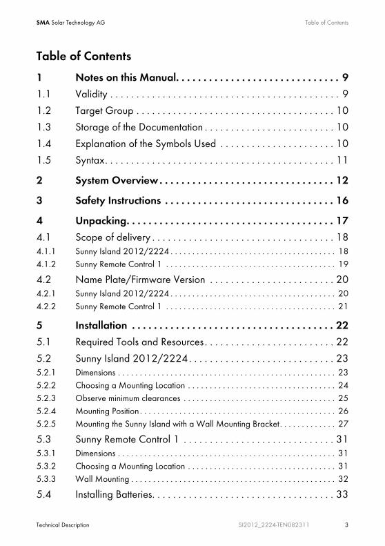
SMA Solar Technology AG Table of Contents
Technical Description SI2012_2224-TEN082311 3
Table of Contents
1 Notes on this Manual. . . . . . . . . . . . . . . . . . . . . . . . . . . . . . 9
1.1 Validity . . . . . . . . . . . . . . . . . . . . . . . . . . . . . . . . . . . . . . . . . . . . 9
1.2 Target Group . . . . . . . . . . . . . . . . . . . . . . . . . . . . . . . . . . . . . . 10
1.3 Storage of the Documentation . . . . . . . . . . . . . . . . . . . . . . . . . 10
1.4 Explanation of the Symbols Used . . . . . . . . . . . . . . . . . . . . . . 10
1.5 Syntax. . . . . . . . . . . . . . . . . . . . . . . . . . . . . . . . . . . . . . . . . . . . 11
2 System Overview. . . . . . . . . . . . . . . . . . . . . . . . . . . . . . . . 12
3 Safety Instructions . . . . . . . . . . . . . . . . . . . . . . . . . . . . . . . 16
4 Unpacking. . . . . . . . . . . . . . . . . . . . . . . . . . . . . . . . . . . . . . 17
4.1 Scope of delivery . . . . . . . . . . . . . . . . . . . . . . . . . . . . . . . . . . . 184.1.1 Sunny Island 2012/2224 . . . . . . . . . . . . . . . . . . . . . . . . . . . . . . . . . . . . . . 184.1.2 Sunny Remote Control 1 . . . . . . . . . . . . . . . . . . . . . . . . . . . . . . . . . . . . . . . 19
4.2 Name Plate/Firmware Version . . . . . . . . . . . . . . . . . . . . . . . . 204.2.1 Sunny Island 2012/2224 . . . . . . . . . . . . . . . . . . . . . . . . . . . . . . . . . . . . . . 204.2.2 Sunny Remote Control 1 . . . . . . . . . . . . . . . . . . . . . . . . . . . . . . . . . . . . . . . 21
5 Installation . . . . . . . . . . . . . . . . . . . . . . . . . . . . . . . . . . . . . 22
5.1 Required Tools and Resources . . . . . . . . . . . . . . . . . . . . . . . . . 22
5.2 Sunny Island 2012/2224. . . . . . . . . . . . . . . . . . . . . . . . . . . . 235.2.1 Dimensions . . . . . . . . . . . . . . . . . . . . . . . . . . . . . . . . . . . . . . . . . . . . . . . . . . 235.2.2 Choosing a Mounting Location . . . . . . . . . . . . . . . . . . . . . . . . . . . . . . . . . . 245.2.3 Observe minimum clearances . . . . . . . . . . . . . . . . . . . . . . . . . . . . . . . . . . . 255.2.4 Mounting Position . . . . . . . . . . . . . . . . . . . . . . . . . . . . . . . . . . . . . . . . . . . . . 265.2.5 Mounting the Sunny Island with a Wall Mounting Bracket. . . . . . . . . . . . . 27
5.3 Sunny Remote Control 1 . . . . . . . . . . . . . . . . . . . . . . . . . . . . . 315.3.1 Dimensions . . . . . . . . . . . . . . . . . . . . . . . . . . . . . . . . . . . . . . . . . . . . . . . . . . 315.3.2 Choosing a Mounting Location . . . . . . . . . . . . . . . . . . . . . . . . . . . . . . . . . . 315.3.3 Wall Mounting . . . . . . . . . . . . . . . . . . . . . . . . . . . . . . . . . . . . . . . . . . . . . . . 32
5.4 Installing Batteries. . . . . . . . . . . . . . . . . . . . . . . . . . . . . . . . . . . 33
Table of Contents SMA Solar Technology AG
4 SI2012_2224-TEN082311 Technical Description
6 Opening and Closing. . . . . . . . . . . . . . . . . . . . . . . . . . . . . 36
6.1 Opening the Sunny Island . . . . . . . . . . . . . . . . . . . . . . . . . . . . 37
6.2 Closing the Sunny Island . . . . . . . . . . . . . . . . . . . . . . . . . . . . . 38
7 Sunny Island Electrical Connection . . . . . . . . . . . . . . . . . . 39
7.1 At a Glance . . . . . . . . . . . . . . . . . . . . . . . . . . . . . . . . . . . . . . . 40
7.2 DC connection . . . . . . . . . . . . . . . . . . . . . . . . . . . . . . . . . . . . . 437.2.1 Grounding . . . . . . . . . . . . . . . . . . . . . . . . . . . . . . . . . . . . . . . . . . . . . . . . . . 437.2.2 Connecting the Battery . . . . . . . . . . . . . . . . . . . . . . . . . . . . . . . . . . . . . . . . . 447.2.3 Connecting the Sunny Island . . . . . . . . . . . . . . . . . . . . . . . . . . . . . . . . . . . . 45
7.3 AC Connection. . . . . . . . . . . . . . . . . . . . . . . . . . . . . . . . . . . . . 467.3.1 Grounding . . . . . . . . . . . . . . . . . . . . . . . . . . . . . . . . . . . . . . . . . . . . . . . . . . 477.3.2 AC1 (Loads/Sunny Boys) . . . . . . . . . . . . . . . . . . . . . . . . . . . . . . . . . . . . . . 487.3.3 AC2 (Gen/Grid) . . . . . . . . . . . . . . . . . . . . . . . . . . . . . . . . . . . . . . . . . . . . . 50
7.4 Sunny Remote Control 1 . . . . . . . . . . . . . . . . . . . . . . . . . . . . . 51
7.5 Communication . . . . . . . . . . . . . . . . . . . . . . . . . . . . . . . . . . . . 537.5.1 Communication with Sunny Island . . . . . . . . . . . . . . . . . . . . . . . . . . . . . . . . 537.5.2 Communication With External Devices . . . . . . . . . . . . . . . . . . . . . . . . . . . . 56
7.6 Additional Connections . . . . . . . . . . . . . . . . . . . . . . . . . . . . . . 597.6.1 Battery Temperature Sensor . . . . . . . . . . . . . . . . . . . . . . . . . . . . . . . . . . . . . 597.6.2 Battery Current Sensor . . . . . . . . . . . . . . . . . . . . . . . . . . . . . . . . . . . . . . . . . 617.6.3 Multi-function Relays 1 and 2 . . . . . . . . . . . . . . . . . . . . . . . . . . . . . . . . . . . 637.6.4 BatVtgOut Power Supply . . . . . . . . . . . . . . . . . . . . . . . . . . . . . . . . . . . . . . . 667.6.5 DigIn Digital Input. . . . . . . . . . . . . . . . . . . . . . . . . . . . . . . . . . . . . . . . . . . . . 66
7.7 Configuring a System with Several Sunny Islands. . . . . . . . . . 68
7.8 Concluding Tasks . . . . . . . . . . . . . . . . . . . . . . . . . . . . . . . . . . . 69
8 Control Elements . . . . . . . . . . . . . . . . . . . . . . . . . . . . . . . . 70
8.1 Sunny Island . . . . . . . . . . . . . . . . . . . . . . . . . . . . . . . . . . . . . . . 708.1.1 Control Panel on the Enclosure . . . . . . . . . . . . . . . . . . . . . . . . . . . . . . . . . . 708.1.2 Control Panel Buttons . . . . . . . . . . . . . . . . . . . . . . . . . . . . . . . . . . . . . . . . . . 708.1.3 Meaning of the Light-Emitting Diodes (LEDs) . . . . . . . . . . . . . . . . . . . . . . . . 70
8.2 Sunny Remote Control 1 . . . . . . . . . . . . . . . . . . . . . . . . . . . . . 72

SMA Solar Technology AG Table of Contents
Technical Description SI2012_2224-TEN082311 5
8.2.1 Display Messages . . . . . . . . . . . . . . . . . . . . . . . . . . . . . . . . . . . . . . . . . . . . 738.2.2 Key . . . . . . . . . . . . . . . . . . . . . . . . . . . . . . . . . . . . . . . . . . . . . . . . . . . . . . . . 738.2.3 Rotating Pushbutton . . . . . . . . . . . . . . . . . . . . . . . . . . . . . . . . . . . . . . . . . . . 748.2.4 MMC/SD card. . . . . . . . . . . . . . . . . . . . . . . . . . . . . . . . . . . . . . . . . . . . . . . 74
9 (First) Commissioning. . . . . . . . . . . . . . . . . . . . . . . . . . . . . 75
9.1 Requirements . . . . . . . . . . . . . . . . . . . . . . . . . . . . . . . . . . . . . . 75
9.2 Starting the Quick Configuration Guide (QCG) . . . . . . . . . . . 76
9.3 Commissioning the Battery Current Sensor . . . . . . . . . . . . . . . 81
10 Operating the Sunny Island . . . . . . . . . . . . . . . . . . . . . . . 83
10.1 Switching On and Off . . . . . . . . . . . . . . . . . . . . . . . . . . . . . . . 8310.1.1 Switching On/Starting . . . . . . . . . . . . . . . . . . . . . . . . . . . . . . . . . . . . . . . . . 8310.1.2 Stopping . . . . . . . . . . . . . . . . . . . . . . . . . . . . . . . . . . . . . . . . . . . . . . . . . . . . 8510.1.3 Switching Off . . . . . . . . . . . . . . . . . . . . . . . . . . . . . . . . . . . . . . . . . . . . . . . . 8710.1.4 Disconnecting the Device from Voltage Sources . . . . . . . . . . . . . . . . . . . . . 8710.1.5 Restarting the System after Automatic Shutdown. . . . . . . . . . . . . . . . . . . . . 88
10.2 Navigation Area . . . . . . . . . . . . . . . . . . . . . . . . . . . . . . . . . . . 8910.2.1 Standard View 1 . . . . . . . . . . . . . . . . . . . . . . . . . . . . . . . . . . . . . . . . . . . . . 9210.2.2 Standard View 2 . . . . . . . . . . . . . . . . . . . . . . . . . . . . . . . . . . . . . . . . . . . . . 9310.2.3 Select menu . . . . . . . . . . . . . . . . . . . . . . . . . . . . . . . . . . . . . . . . . . . . . . . . . 9710.2.4 Selecting Parameters . . . . . . . . . . . . . . . . . . . . . . . . . . . . . . . . . . . . . . . . . . 9910.2.5 Selecting Events . . . . . . . . . . . . . . . . . . . . . . . . . . . . . . . . . . . . . . . . . . . . . . 9910.2.6 Selecting Warnings and Faults. . . . . . . . . . . . . . . . . . . . . . . . . . . . . . . . . . 100
10.3 Making adjustments . . . . . . . . . . . . . . . . . . . . . . . . . . . . . . . . 10110.3.1 Adjusting parameters . . . . . . . . . . . . . . . . . . . . . . . . . . . . . . . . . . . . . . . . . 10110.3.2 Setting the Installer Password. . . . . . . . . . . . . . . . . . . . . . . . . . . . . . . . . . . 10210.3.3 Accessing Parameters Directly . . . . . . . . . . . . . . . . . . . . . . . . . . . . . . . . . . 10510.3.4 Meter Compact . . . . . . . . . . . . . . . . . . . . . . . . . . . . . . . . . . . . . . . . . . . . . 105
10.4 Saving Data onto a MMC/SD Card. . . . . . . . . . . . . . . . . . . 10710.4.1 Inserting the Card . . . . . . . . . . . . . . . . . . . . . . . . . . . . . . . . . . . . . . . . . . . . 11110.4.2 Removing the Card. . . . . . . . . . . . . . . . . . . . . . . . . . . . . . . . . . . . . . . . . . . 11210.4.3 Loading and Saving Parameters . . . . . . . . . . . . . . . . . . . . . . . . . . . . . . . . 11210.4.4 Writing Log Data . . . . . . . . . . . . . . . . . . . . . . . . . . . . . . . . . . . . . . . . . . . . 113
Table of Contents SMA Solar Technology AG
6 SI2012_2224-TEN082311 Technical Description
10.4.5 Show Status . . . . . . . . . . . . . . . . . . . . . . . . . . . . . . . . . . . . . . . . . . . . . . . . 11310.4.6 Updating Firmware. . . . . . . . . . . . . . . . . . . . . . . . . . . . . . . . . . . . . . . . . . . 114
11 Additional Functions . . . . . . . . . . . . . . . . . . . . . . . . . . . . 117
11.1 Load shedding . . . . . . . . . . . . . . . . . . . . . . . . . . . . . . . . . . . . 117
11.2 Sleep Mode . . . . . . . . . . . . . . . . . . . . . . . . . . . . . . . . . . . . . . 118
11.3 Search Mode . . . . . . . . . . . . . . . . . . . . . . . . . . . . . . . . . . . . . 118
11.4 Time-controlled Operation . . . . . . . . . . . . . . . . . . . . . . . . . . . 119
11.5 Overload and Short Circuit Behavior . . . . . . . . . . . . . . . . . . 119
11.6 Device Failure and Autostart . . . . . . . . . . . . . . . . . . . . . . . . . 119
12 Battery management . . . . . . . . . . . . . . . . . . . . . . . . . . . . 120
12.1 Battery temperature. . . . . . . . . . . . . . . . . . . . . . . . . . . . . . . . 120
12.2 Start Options . . . . . . . . . . . . . . . . . . . . . . . . . . . . . . . . . . . . . 121
12.3 Charge State/SOC and SOH . . . . . . . . . . . . . . . . . . . . . . . . 121
12.4 Charge Control . . . . . . . . . . . . . . . . . . . . . . . . . . . . . . . . . . . 12212.4.1 Boost Charge . . . . . . . . . . . . . . . . . . . . . . . . . . . . . . . . . . . . . . . . . . . . . . . 12412.4.2 Full Charge . . . . . . . . . . . . . . . . . . . . . . . . . . . . . . . . . . . . . . . . . . . . . . . . . 12412.4.3 Equalization Charge . . . . . . . . . . . . . . . . . . . . . . . . . . . . . . . . . . . . . . . . . 12612.4.4 Manual Equalization Charge. . . . . . . . . . . . . . . . . . . . . . . . . . . . . . . . . . . 12712.4.5 Silent Mode . . . . . . . . . . . . . . . . . . . . . . . . . . . . . . . . . . . . . . . . . . . . . . . . 127
12.5 Battery Preservation Mode . . . . . . . . . . . . . . . . . . . . . . . . . . 127
12.6 Battery Diagnostics. . . . . . . . . . . . . . . . . . . . . . . . . . . . . . . . . 129
13 Connecting External Sources . . . . . . . . . . . . . . . . . . . . . 130
13.1 Generator. . . . . . . . . . . . . . . . . . . . . . . . . . . . . . . . . . . . . . . . 13013.1.1 Connecting Generator Connections in Parallel . . . . . . . . . . . . . . . . . . . . . 13113.1.2 Generator Start Options. . . . . . . . . . . . . . . . . . . . . . . . . . . . . . . . . . . . . . . 13113.1.3 Generator Operation . . . . . . . . . . . . . . . . . . . . . . . . . . . . . . . . . . . . . . . . . 13513.1.4 Manual Generator Operation . . . . . . . . . . . . . . . . . . . . . . . . . . . . . . . . . . 13513.1.5 Automatic Generator Operation . . . . . . . . . . . . . . . . . . . . . . . . . . . . . . . . 13713.1.6 Limits and Power Adjustment . . . . . . . . . . . . . . . . . . . . . . . . . . . . . . . . . . . 14113.1.7 Run Times . . . . . . . . . . . . . . . . . . . . . . . . . . . . . . . . . . . . . . . . . . . . . . . . . . 143

SMA Solar Technology AG Table of Contents
Technical Description SI2012_2224-TEN082311 7
13.1.8 Operation Together With Sunny Boys . . . . . . . . . . . . . . . . . . . . . . . . . . . . 14413.1.9 Stopping the Generator . . . . . . . . . . . . . . . . . . . . . . . . . . . . . . . . . . . . . . . 14513.1.10 Failures . . . . . . . . . . . . . . . . . . . . . . . . . . . . . . . . . . . . . . . . . . . . . . . . . . . . 146
13.2 Grid . . . . . . . . . . . . . . . . . . . . . . . . . . . . . . . . . . . . . . . . . . . . 14613.2.1 Conditions. . . . . . . . . . . . . . . . . . . . . . . . . . . . . . . . . . . . . . . . . . . . . . . . . . 14713.2.2 Stand-Alone Grid Operation . . . . . . . . . . . . . . . . . . . . . . . . . . . . . . . . . . . 14713.2.3 Grid Reconnection . . . . . . . . . . . . . . . . . . . . . . . . . . . . . . . . . . . . . . . . . . . 14713.2.4 Grid Operation. . . . . . . . . . . . . . . . . . . . . . . . . . . . . . . . . . . . . . . . . . . . . . 14813.2.5 Grid Failure. . . . . . . . . . . . . . . . . . . . . . . . . . . . . . . . . . . . . . . . . . . . . . . . . 14913.2.6 Failures . . . . . . . . . . . . . . . . . . . . . . . . . . . . . . . . . . . . . . . . . . . . . . . . . . . . 14913.2.7 Limits and Power Adjustment . . . . . . . . . . . . . . . . . . . . . . . . . . . . . . . . . . . 14913.2.8 Operation Together With Sunny Boys . . . . . . . . . . . . . . . . . . . . . . . . . . . . 150
13.3 Generator and Grid. . . . . . . . . . . . . . . . . . . . . . . . . . . . . . . . 151
14 Relay . . . . . . . . . . . . . . . . . . . . . . . . . . . . . . . . . . . . . . . . . 152
15 Sunny Boy in the Island Grid System . . . . . . . . . . . . . . . 154
15.1 Setting the Stand-alone Grid Parameters. . . . . . . . . . . . . . . . 154
15.2 Frequency Shift Power Control (FSPC) . . . . . . . . . . . . . . . . . 156
16 Maintenance and Care . . . . . . . . . . . . . . . . . . . . . . . . . . 158
16.1 Enclosure . . . . . . . . . . . . . . . . . . . . . . . . . . . . . . . . . . . . . . . . 158
16.2 The Sunny Island's Control Panel. . . . . . . . . . . . . . . . . . . . . . 158
16.3 Sunny Remote Control 1 . . . . . . . . . . . . . . . . . . . . . . . . . . . . 158
16.4 Functional Test . . . . . . . . . . . . . . . . . . . . . . . . . . . . . . . . . . . . 158
16.5 Battery . . . . . . . . . . . . . . . . . . . . . . . . . . . . . . . . . . . . . . . . . . 159
16.6 Disposal . . . . . . . . . . . . . . . . . . . . . . . . . . . . . . . . . . . . . . . . . 159
17 Parameter List Overview. . . . . . . . . . . . . . . . . . . . . . . . . 160
17.1 Display Values . . . . . . . . . . . . . . . . . . . . . . . . . . . . . . . . . . . . 162
17.2 Adjustable System Parameters . . . . . . . . . . . . . . . . . . . . . . . . 166
17.3 Diagnosis . . . . . . . . . . . . . . . . . . . . . . . . . . . . . . . . . . . . . . . . 178
17.4 Events, Warnings and Failures (History) . . . . . . . . . . . . . . . . 182

Table of Contents SMA Solar Technology AG
8 SI2012_2224-TEN082311 Technical Description
17.5 Functions During Operation . . . . . . . . . . . . . . . . . . . . . . . . . . 182
18 Troubleshooting/Problem Solving . . . . . . . . . . . . . . . . . 184
18.1 Error Confirmation . . . . . . . . . . . . . . . . . . . . . . . . . . . . . . . . . 184
18.2 Handling Autostart . . . . . . . . . . . . . . . . . . . . . . . . . . . . . . . . . 184
18.3 Handling Failures Present During Startup . . . . . . . . . . . . . . . 184
18.4 Display of Failures and Events . . . . . . . . . . . . . . . . . . . . . . . . 184
18.5 Events . . . . . . . . . . . . . . . . . . . . . . . . . . . . . . . . . . . . . . . . . . . 185
18.6 Error Categories . . . . . . . . . . . . . . . . . . . . . . . . . . . . . . . . . . . 188
18.7 Warnings and Failure messages . . . . . . . . . . . . . . . . . . . . . . 188
18.8 Troubleshooting . . . . . . . . . . . . . . . . . . . . . . . . . . . . . . . . . . . 192
19 Optional Devices . . . . . . . . . . . . . . . . . . . . . . . . . . . . . . . 195
19.1 External DC fuse. . . . . . . . . . . . . . . . . . . . . . . . . . . . . . . . . . . 195
19.2 External DC charge controllers (optional) . . . . . . . . . . . . . . . 195
19.3 Accessories (Optional). . . . . . . . . . . . . . . . . . . . . . . . . . . . . . 195
19.4 SMA Products (Optional). . . . . . . . . . . . . . . . . . . . . . . . . . . . 196
20 Technical Data . . . . . . . . . . . . . . . . . . . . . . . . . . . . . . . . . 197
20.1 Sunny Island 2012/2224. . . . . . . . . . . . . . . . . . . . . . . . . . . 197
20.2 Sunny Remote Control 1 . . . . . . . . . . . . . . . . . . . . . . . . . . . . 200
21 Contact . . . . . . . . . . . . . . . . . . . . . . . . . . . . . . . . . . . . . . . 201
22 Glossary . . . . . . . . . . . . . . . . . . . . . . . . . . . . . . . . . . . . . . 202

SMA Solar Technology AG Notes on this Manual
Technical Description SI2012_2224-TEN082311 9
1 Notes on this ManualThis technical description explains the functioning, correct installation and operation of a stand-alone grid system. It describes the Sunny Island 2012 / 2224 inverter as well as the Sunny Remote Control 1 display.
Information on the following topics can be found in the respectively labeled sections:
1.1 ValidityThe technical description applies to the Sunny Island 2012 / 2224 firmware versions 2.0 and later (see chapter 4.2 "Name Plate/Firmware Version" (Page 20)).
You can read the firmware version of your Sunny Island 2012 / 2224 on the display using the "312.02 FwVer" parameter (see section 17.3 "Diagnosis" (Page 178)).
The stand-alone grid system devices may only be operated within the intended area of application described in this documentation.
• The use of a stand-alone grid system to power life-sustaining medical devices is not permitted.
• The Sunny Reomet Control 1 is suited only for installation in enclosed spaces (protection rating IP20).
• The Sunny Island 2012 / 2224 has been designed for use at elevations of up to 2600 m above sea level. Please contact SMA Solar Technology AG before using the device at elevations above 2600 m.
A performance loss of 0.5 % per every 100 m is to be expected starting at an elevation of 2000 m above sea level.
- Installation: Chapter 2 "System Overview" (Page 12)
- Commissioning: Chapter 8 "Control Elements" (Page 70)
- Functions: Chapter 11 "Additional Functions" (Page 117)
- Appendix: Chapter 16 "Maintenance and Care" (Page 158)
Information
The following applications are only possible with firmware versions 3.0 and above:
• Connection of two or three Sunny Island 2012 / 2224 devices to a 1-phase parallel system
• Connection of two or three Sunny Island 2012 / 2224 devices to a 3-phase parallel system
Notes on this Manual SMA Solar Technology AG
10 SI2012_2224-TEN082311 Technical Description
Do not use the stand-alone grid system devices for purposes other than those indicated in this technical description. Use of the devices for other purposes can void the warranty as well as damage both the devices and the system.
For further questions, you can call the Sunny Island hotline at
• +49561 95 22 399
• E-Mail: [email protected].
1.2 Target GroupThis technical description is meant both for the installer and the operator of the stand-alone grid system. Some of the tasks described in this document must be performed only by qualified electricians and are labeled accordingly with warnings.
1.3 Storage of the DocumentationThe manuals for the stand-alone grid system and its installed components must be kept in the immediate vicinity of the Sunny Island so as to be accessible at all times.
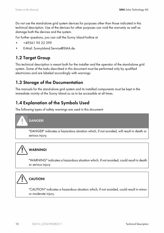
1.4 Explanation of the Symbols UsedThe following types of safety warnings are used in this document:
DANGER!
"DANGER" indicates a hazardous situation which, if not avoided, will result in death or serious injury.
WARNING!
"WARNING" indicates a hazardous situation which, if not avoided, could result in death or serious injury.
CAUTION!
"CAUTION" indicates a hazardous situation which, if not avoided, could result in minor or moderate injury.
SMA Solar Technology AG Notes on this Manual
Technical Description SI2012_2224-TEN082311 11
1.5 SyntaxThe syntax specified here for menus and parameters applies throughout the entire document:
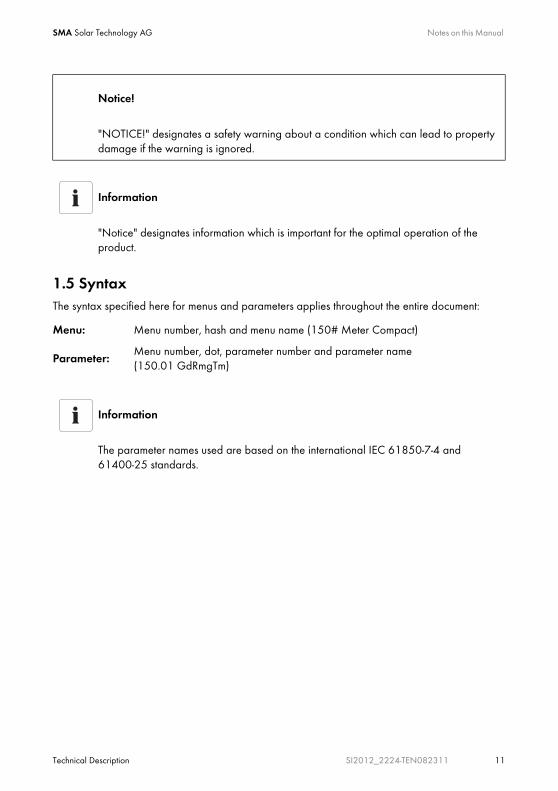
Notice!
"NOTICE!" designates a safety warning about a condition which can lead to property damage if the warning is ignored.
Information
"Notice" designates information which is important for the optimal operation of the product.
Menu: Menu number, hash and menu name (150# Meter Compact)
Parameter:Menu number, dot, parameter number and parameter name (150.01 GdRmgTm)
Information
The parameter names used are based on the international IEC 61850-7-4 and 61400-25 standards.
System Overview SMA Solar Technology AG
12 SI2012_2224-TEN082311 Technical Description
2 System OverviewThe Sunny Island is a bi-directional battery inverter (battery inverter and charger) for off-grid systems. The Sunny Island supplies consumers on the stand-alone grid side and charges battery banks with the energy from grid-feeding units connected on the AC side.
High efficiencyThe comfortable support of AC- and DC coupling as well as the expandability of the systems formed with the Sunny Island guarantee highest flexibility. In addition, innovative technology allows the Sunny Island to achieve a maximum efficiency of more than 93 %. Optimized for partial load operation, its low open-circuit and standby consumption are convincing features. Because of its high overload capability and integrated power management, overdimensioning of the Sunny Island is not necessary.
Multiple Phase / Parallel Connection CapabilitiesThe parallel operation of up to three devices on a single phase of a battery or of three devices on a three-phase system enables the Sunny Island to be used to set up stand-alone power supply systems with outputs of up to 9 kW.
Automatic Generator ControlThanks to its sophisticated generator management it can control connected diesel generators in a particularly gentle and fuel-saving manner. It can also be integrated into the public grid. The Sunny Island can also deactivate loads automatically if the battery does not provide sufficient electrical energy.
Perfected Battery ManagementThe stand-alone grid's critical component, the battery, is monitored diligently and utilized optimally. The intelligent battery management registers the battery's state of charge precisely. This makes possible an improved utilization of the battery capacity, which means that smaller and thus more cost-effective batteries can be used without affecting performance.
In order to prevent premature aging caused by incorrect charging and frequent deep discharge, the Sunny Island has an intelligent charge control and reliable deep discharge protection. Because of these functions the battery service life can be largely extended, in comparison with simpler devices.
DC fuse
WARNING!
The Sunny Island 2012 / 2224 has no internal DC fuse.
Install an external DC fuse between the Sunny Island and the battery (see chapter 7.2 "DC connection" (Page 43)).

SMA Solar Technology AG System Overview
Technical Description SI2012_2224-TEN082311 13
As an external DC fuse, the BatFuse secures the Sunny Island's battery connection leads.
In addition, the BatFuse allows the disconnection of the inverter on the DC side. You will find more information in the technical description of the BatFuse. You can obtain the BatFuse as an accessory from the SMA Solar Technology AG.
Simple Installation and ConfigurationDespite the complex function of this battery inverter, the Sunny Island is easy to install and configure. All the settings required for operation can be quickly and easily programmed in ten steps using the "Quick Configuration Guide". Using the central operation concept referred to as "Single Point of Operation", the system/cluster parameters are only set on the master device; all other devices adopt the configuration automatically.
Menu Navigation and Data ArchivingThe easy-to-understand menu navigation allows quick access to all important data, even while the system is running. The Sunny Island can be controlled easily with the Sunny Remote Control 1(SRC-1) external display. An MMC/SD card provides simple system supervision and thus simplifies any service tasks.
The Sunny Island monitors the set voltage and frequency limits on the grid and generator. If these limits are not observed, it disconnects from the external source without interruption and changes to stand-alone grid operation. The Sunny Island also has an integrated anti-islanding process in order to prevent unintended islanding on the public grid. If this process is triggered, the system will also change to stand-alone mode without any interruption.
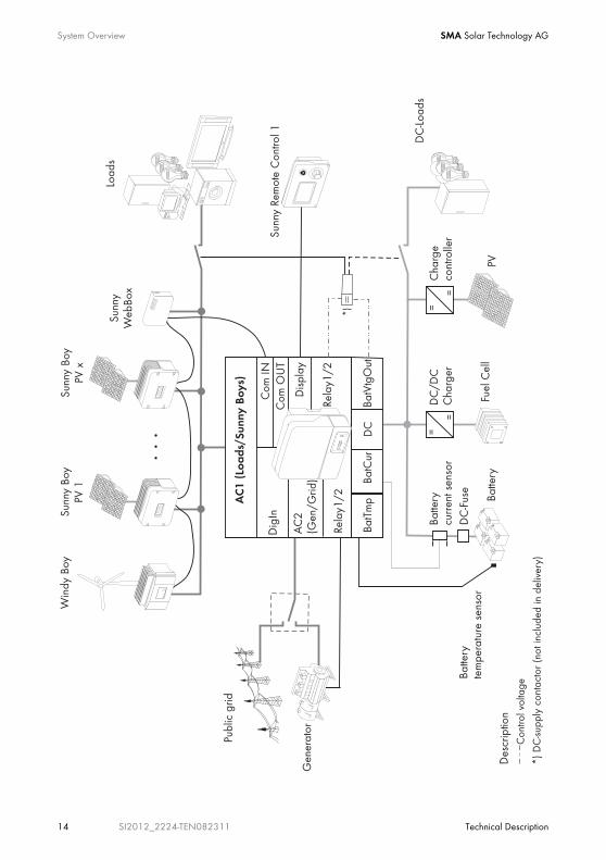
You can use the Sunny Island within various system configurations.
• The graphic on the following page shows which components can be integrated into a stand-alone grid system.
• The graphics on the page after next show the different wiring options (1-phase, 1-phase parallel and 3-phase).
Saving Data
Always use the MMC/SD card for saving data and events. This way, in case of a failure, the SMA Solar Technology AG can help you quickly.
System Overview SMA Solar Technology AG
14 SI2012_2224-TEN082311 Technical Description
=
=
AC
1 (L
oads
/Sun
ny B
oys)
Dig
In
DC
Com
IN
Rela
y1/2
Win
dy B
oySu
nny
Boy
PV 1
Sunn
y Bo
yPV
x
Sunn
yW
ebBo
x
Load
s
DC
/DC
Cha
rger
Fuel
Cel
lBa
ttery
Gen
erat
or
Publ
ic g
rid
POWER
SYSTEM
REPORT
MEMORY
SMACOM
NETCOM
USBCOM
Batte
ryte
mpe
ratu
re s
enso
r
*)
Des
crip
tion
Con
trol v
olta
ge
*) D
C-su
pply
con
tact
or (n
ot in
clud
ed in
del
iver
y)
=
=
Cha
rge
cont
rolle
r
PV
BatT
mp
BatC
ur
Batte
rycu
rren
t sen
sor
DC
-Load
s
BatV
tgO
ut
AC
2(G
en/G
rid)
Rela
y1/2
Disp
lay
Sunn
y Re
mot
e C
ontro
l 1
DC
-Fus
e
Com
OU
T

SMA Solar Technology AG System Overview
Technical Description SI2012_2224-TEN082311 15
1-phasig 1-phasig parallel
3-phasig

Safety Instructions SMA Solar Technology AG
16 SI2012_2224-TEN082311 Technical Description
3 Safety InstructionsPlease follow all operating and safety instructions in this manual. Failure to follow these instructions could result in damage to the device and personal hazard.
DANGER!
Risk of lethal electric shock when opening the devices.
• Installation and repair of the devices in the stand-alone grid system must be carried out exclusively by qualified personnel.
• Observe all provisions and safety notices.
• Before starting work disconnect all live components by using circuit breakers.
• Secure circuit breakers against accidental switching on.
Information
Be sure to observe all applicable regional standards and guidelines.
SMA Solar Technology AG Unpacking
Technical Description SI2012_2224-TEN082311 17
4 UnpackingBefore installing the Sunny Island and the Sunny Remote Control 1, make sure that all parts are included in the delivery.
• Carefully check the packaging and the devices for any signs of damage.
• Ensure that all parts are included in the delivery (see section4.1 "Scope of delivery" (Page 18)).
If something is missing or if the devices have been damaged during shipment, contact the SMA Solar Technology AG immediately. Further information is provided in section .21 "Contact" (Page 201).
Information
Keep the packaging in case you need to return the Sunny Island, the Sunny Remote Control 1 or their accessories.

Unpacking SMA Solar Technology AG
18 SI2012_2224-TEN082311 Technical Description
4.1 Scope of delivery
4.1.1 Sunny Island 2012/2224The following elements are included:
A 1 Sunny Island 2012/2224 and lid.
B 1 Wall bracket
C 1 Battery temperature sensor
D 2 3-pin print terminals (for connecting relays 1 & 2)
E 2 4-pole print terminals for connecting battery temperature sensors
F 1 silicone tube 10 mm x 0.5 m
G 1 Technical Description (Manual)
H 1 M25 metric-thread cable screw
A
G
2x E 2x D
BF
C
H
SMA Solar Technology AG Unpacking
Technical Description SI2012_2224-TEN082311 19
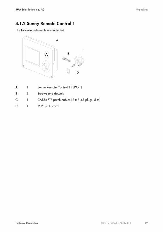
4.1.2 Sunny Remote Control 1The following elements are included:
A 1 Sunny Remote Control 1 (SRC-1)
B 2 Screws and dowels
C 1 CAT5e-FTP patch cables (2 x RJ45 plugs, 5 m)
D 1 MMC/SD card
A
CB
D

Unpacking SMA Solar Technology AG
20 SI2012_2224-TEN082311 Technical Description
4.2 Name Plate/Firmware Version
4.2.1 Sunny Island 2012/2224You can identify the Sunny Island by the type plate and firmware version. The following diagram shows the type plate of the Sunny Island 2224.
• The name plate is located outside on the right side of the housing.
• You can read the the firmware version of your device on the display using the "331.02 FwVer" parameter (see section17.3 "Diagnosis" (Page 178).
SMA Solar Technology AG Unpacking
Technical Description SI2012_2224-TEN082311 21
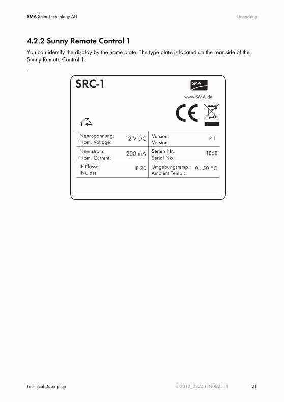
4.2.2 Sunny Remote Control 1You can identify the display by the name plate. The type plate is located on the rear side of the Sunny Remote Control 1.
.

Installation SMA Solar Technology AG
22 SI2012_2224-TEN082311 Technical Description
5 InstallationTake note of the required installation conditions specified in the sections below before mounting, installing and commissioning the Sunny Island.
5.1 Required Tools and ResourcesThe following tools and materials are recommended for mounting and installing the island grid system:
Tools (not included in delivery)
Stripping pliers
Drill (e.g. stone drill), Ø 6 to 10 mm
Drill
Crimping tool for cable lug
Torque wrench (4 Nm to 10 Nm), 13 mm socket wrench
4 mm allen wrench
Cable knife
Ratchet (including extension)
Combination pliers
13 mm open end/ring wrench
Multimeter
Diagonal cutting pliers
Phillips screwdriver, PH1and PH2
Flathead screwdriver, 0.4 x 2.5 mm/1.0 x 10 mm/1.0 x 5.5 mm
Spirit level
Material (not included in delivery)
Cable end sleeves
Wall anchors for the wall bracket (e.g. SX 10)
Cable ties
AC cable (3 leads, 2.5 mm² each)
DC cable (95 mm² max.)
Cable lug for DC cable
hexagon bolts, 8x60 mm, washers
SMA Solar Technology AG Installation
Technical Description SI2012_2224-TEN082311 23
5.2 Sunny Island 2012/2224
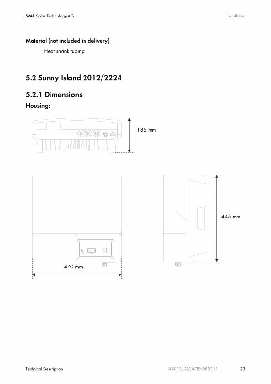
5.2.1 DimensionsHousing:
Heat shrink tubing
Material (not included in delivery)
470 mm
445 mm
185 mm
Installation SMA Solar Technology AG
24 SI2012_2224-TEN082311 Technical Description
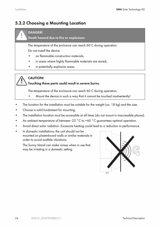
5.2.2 Choosing a Mounting Location
• The location for the installation must be suitable for the weight (ca. 18 kg) and the size.
• Choose a solid fundament for mounting.
• The installation location must be accessible at all times (do not mount in inaccessible places).
• An ambient temperature of between -25 °C to +60 °C guarantees optimal operation.
• Avoid direct solar radiation. Excessive heating could lead to a reduction in performance.
• In domestic installations, the unit should not be mounted on plasterboard walls or similar materials in order to avoid audible vibrations.
The Sunny Island can make noises when in use that may be irritating in a domestic setting.
DANGER!
Death hazard due to fire or explosions
The temperature of the enclosure can reach 60 C during operation.
Do not install the device
• on flammable construction materials,
• in areas where highly flammable materials are stored,
• in potentially explosive areas
CAUTION!
Touching these parts could result in severe burns.
The temperature of the enclosure can reach 60 C during operation.
• Mount the device in such a way that it cannot be touched inadvertently!

SMA Solar Technology AG Installation
Technical Description SI2012_2224-TEN082311 25
5.2.3 Observe minimum clearancesThe following minimum clearances to walls, other devices or objects must be observed to guarantee sufficient heat dissipation.
All external cables are connected through the underside of the housing. This requires a minimum clearance of at least 50 cm.
Direction Minimum clearance
sides 10 cm
above 30 cm
below 50 cm
in front 5 cm
Sufficient Ventilation
When installing the in smaller rooms, make sure that adequate ventilation is available. During operation the device produces heat which must be dissipated.

Installation SMA Solar Technology AG
26 SI2012_2224-TEN082311 Technical Description
5.2.4 Mounting Position
• Mount the device only vertically or with a backward inclination of at most 15°!
• Do not mount the device with a forward inclination!
• Do not mount the device lying flat on its back!
• Mount the device at eye level.
NOTICE!
Short-circuit due to condensation
If the device is in operation while lying flat, water can accumulate due to condensation.
• Operate the device only while it hangs vertically on a wall.

SMA Solar Technology AG Installation
Technical Description SI2012_2224-TEN082311 27
5.2.5 Mounting the Sunny Island with a Wall Mounting Bracket1. Use the wall bracket as a drilling template.
.
Number of drilled holes used
• When mounting onto a wall, use at least two of the horizontal holes and the lowest one in the middle.
• When mounting onto a post use at least three of the holes in the middle (use the superior one in any case).
Mounting Material
When mounting the wall bracket use mounting material which is suited to the fundament. In doing this, observe that the weight of the Sunny Island is approximately 18 kg.
315.9 mm
170 mm
260 mm
Installation SMA Solar Technology AG
28 SI2012_2224-TEN082311 Technical Description
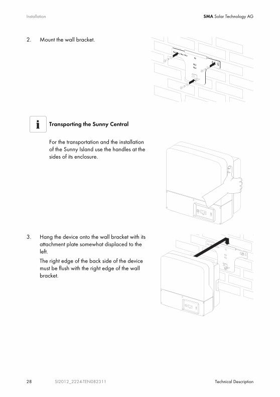
2. Mount the wall bracket.
3. Hang the device onto the wall bracket with its attachment plate somewhat displaced to the left.
The right edge of the back side of the device must be flush with the right edge of the wall bracket.
Transporting the Sunny Central
For the transportation and the installation of the Sunny Island use the handles at the sides of its enclosure.

SMA Solar Technology AG Installation
Technical Description SI2012_2224-TEN082311 29
4. Check on both sides to see that the device sits correctly.
5. Secure the enclosure so it cannot be accidentally lifted up.
Shove the Sunny Island toward the right on the wall bracket until it snaps into place with the safety stud on its back side.
6. Check to see that the device sits correctly.
Installation SMA Solar Technology AG
30 SI2012_2224-TEN082311 Technical Description
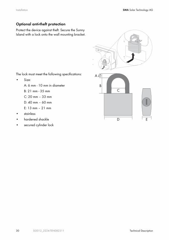
Optional anti-theft protectionProtect the device against theft. Secure the Sunny Island with a lock onto the wall mounting bracket.
The lock must meet the following specifications:
• Size:
A: 6 mm - 10 mm in diameter
B: 21 mm - 35 mm
C: 20 mm – 33 mm
D: 40 mm – 60 mm
E: 13 mm – 21 mm
• stainless
• hardened shackle
• secured cylinder lock

SMA Solar Technology AG Installation
Technical Description SI2012_2224-TEN082311 31
5.3 Sunny Remote Control 1
5.3.1 DimensionsThe external display has the following dimensions:
5.3.2 Choosing a Mounting Location• The installation location must be easily accessible.
Using the display, you can control the Sunny Island and with it the island grid system.
• Choose a solid fundament for mounting.
• Protect the Sunny Remote Control 1 from dust, wet conditions, corrosive substances and vapors.
• An ambient temperature of between 0 °C to 50 °C guarantees optimal operation.
• Avoid direct solar radiation.
Distance between the Sunny Remote Control 1 and the Sunny Island
The communication cable between the Sunny Island the Sunny Remote Control 1 must not exceed 20 m in length.
Installation SMA Solar Technology AG
32 SI2012_2224-TEN082311 Technical Description
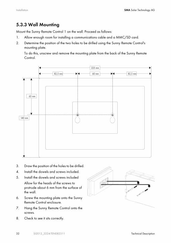
5.3.3 Wall MountingMount the Sunny Remote Control 1 on the wall. Proceed as follows:
1. Allow enough room for installing a communications cable and a MMC/SD card.
2. Determine the position of the two holes to be drilled using the Sunny Remote Control's mounting plate.
To do this, unscrew and remove the mounting plate from the back of the Sunny Remote Control.
3. Draw the position of the holes to be drilled.
4. Install the dowels and screws included.
5. Install the dowels and screws included
Allow for the heads of the screws to protrude about 6 mm from the surface of the wall.
6. Screw the mounting plate onto the Sunny Remote Control enclosure.
7. Hang the Sunny Remote Control onto the screws.
8. Check to see it sits correctly.
SMA Solar Technology AG Installation
Technical Description SI2012_2224-TEN082311 33
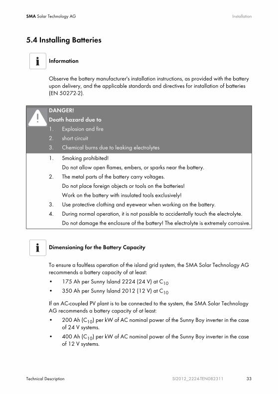
5.4 Installing Batteries
Information
Observe the battery manufacturer's installation instructions, as provided with the battery upon delivery, and the applicable standards and directives for installation of batteries (EN 50272-2).
DANGER!
Death hazard due to
1. Explosion and fire
2. short circuit
3. Chemical burns due to leaking electrolytes
1. Smoking prohibited!
Do not allow open flames, embers, or sparks near the battery.
2. The metal parts of the battery carry voltages.
Do not place foreign objects or tools on the batteries!
Work on the battery with insulated tools exclusively!
3. Use protective clothing and eyewear when working on the battery.
4. During normal operation, it is not possible to accidentally touch the electrolyte.
Do not damage the enclosure of the battery! The electrolyte is extremely corrosive.
Dimensioning for the Battery Capacity
To ensure a faultless operation of the island grid system, the SMA Solar Technology AG recommends a battery capacity of at least:
• 175 Ah per Sunny Island 2224 (24 V) at C10
• 350 Ah per Sunny Island 2012 (12 V) at C10
If an AC-coupled PV plant is to be connected to the system, the SMA Solar Technology AG recommends a battery capacity of at least:
• 200 Ah (C10) per kW of AC nominal power of the Sunny Boy inverter in the case of 24 V systems.
• 400 Ah (C10) per kW of AC nominal power of the Sunny Boy inverter in the case of 12 V systems.

Installation SMA Solar Technology AG
34 SI2012_2224-TEN082311 Technical Description
Batteries must be accommodated in protected rooms, and sufficient ventilation of the installation location must be ensured. In the case of batteries which are connected to one Sunny Island exclusively, there is no need for protection against direct or indirect contact, due to the safety low-voltage.
It is not necessary to install such batteries in a separate battery room, or in a self-contained electrical facility.
The necessary air volume flow for ventilation of the room which accommodates the batteries is calculated as per EN 50272-2 as follows:
Sufficient dissipation of explosive gases is not always ensured in the vicinity of the battery. Therefore, a safety distance must be observed, in the form of an air clearance in which no sparks or smoldering materials are allowed.
The clearance distance is calculated as follows:
Finally, install the battery bank in accordance with the installation instructions provided by the battery manufacturer.
Q = 0,05 * n * IGas * C10/100 [m³/h]
Q = required air flow volume
n = Number of cells
IGas = maximal finishing charge rate
with C10 as the 10 hour nominal capacity in [Ah].
The cross-sectional area of the ventilation inlets and outlets (in the case of natural ventilation) is calculated according to the following formula:
A = 28 * Q [cm2]
d = 5,76 * (C10)1/3 [cm]
Installation of a battery with liquid eletrolyte.
With closed batteries, installation in an acid-resistant collecting tray is to be provided for so that, in the event of a fault, leaking electrolyte cannot cause further damage.
SMA Solar Technology AG Installation
Technical Description SI2012_2224-TEN082311 35
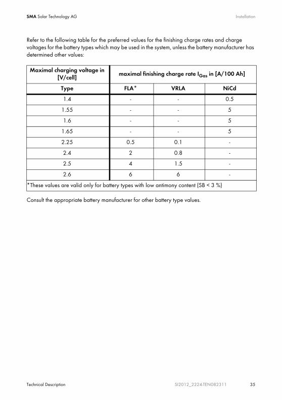
Refer to the following table for the preferred values for the finishing charge rates and charge voltages for the battery types which may be used in the system, unless the battery manufacturer has determined other values:
Consult the appropriate battery manufacturer for other battery type values.
Maximal charging voltage in [V/cell]
maximal finishing charge rate IGas in [A/100 Ah]
Type FLA* VRLA NiCd
1.4 - - 0.5
1.55 - - 5
1.6 - - 5
1.65 - - 5
2.25 0.5 0.1 -
2.4 2 0.8 -
2.5 4 1.5 -
2.6 6 6 -
*These values are valid only for battery types with low antimony content (SB < 3 %)

Opening and Closing SMA Solar Technology AG
36 SI2012_2224-TEN082311 Technical Description
6 Opening and Closing
1. Shut down the Sunny Island.
2. Disconnect the Sunny Island from all voltage sources (battery, generator, grid). (see chapter 10.1.2 "Stopping" (Page 85) and 10.1.3 "Switching Off" (Page 87)).
3. Ensure that the system cannot be accidentally switched on again.
Enclosure lid
Only remove the lower enclosure lid from the Sunny Island when you want to mount, install or maintain it.
- A = upper enclosure cover
- B = lower enclosure cover
- C = control area
DANGER!
Risk of lethal electric shock
High voltages are present in the device!
• Only qualified personnel should open the device!
• Do not open the lower enclosure cover!
After the system has been disconnected (see chapter 10.1.4 "Disconnecting the Device from Voltage Sources" (Page 87)) there are still dangerous voltages present for up to 15 minutes.
• Follow the instructions!
A
B
C

SMA Solar Technology AG Opening and Closing
Technical Description SI2012_2224-TEN082311 37
6.1 Opening the Sunny Island
1. Loosen the six non-removable allen screws on the lower cover (B).
2. Remove the cover carefully.
3. Unplug the control area cable from the inner side of the enclosure cover (in the new devices the cable is not in place).
4. Keep the cover in a safe place.
NOTICE!
The components in the Sunny Island (e.g., communications interface) can be damaged by an electrostatic discharge!
• When working on the Sunny Island and when handling the components observe all ESD safety regulations.
• Eliminate static charge by touching the grounded metal casing.
• Only then should you begin any work.
B
D
Opening and Closing SMA Solar Technology AG
38 SI2012_2224-TEN082311 Technical Description
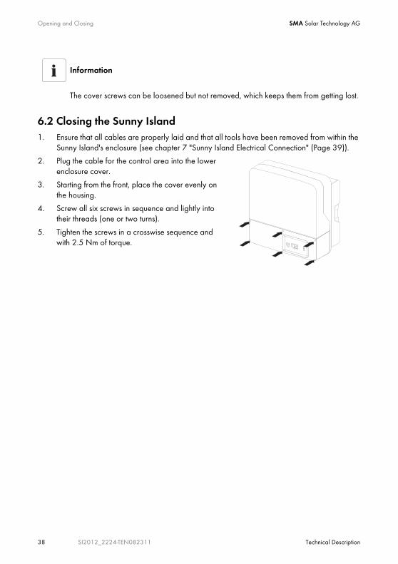
6.2 Closing the Sunny Island1. Ensure that all cables are properly laid and that all tools have been removed from within the
Sunny Island's enclosure (see chapter 7 "Sunny Island Electrical Connection" (Page 39)).
2. Plug the cable for the control area into the lower enclosure cover.
3. Starting from the front, place the cover evenly on the housing.
4. Screw all six screws in sequence and lightly into their threads (one or two turns).
5. Tighten the screws in a crosswise sequence and with 2.5 Nm of torque.
Information
The cover screws can be loosened but not removed, which keeps them from getting lost.

SMA Solar Technology AG Sunny Island Electrical Connection
Technical Description SI2012_2224-TEN082311 39
7 Sunny Island Electrical Connection
DANGER!
Risk of lethal electric shock due to wrong connection
• Only qualified personnel should install the devices' connections.
• Install line safety switches (max. 25 A) before the Sunny Island as seen from the grid side.
• Follow every safety notice in this chapter during installation.
NOTICE!
The components in the Sunny Island (e.g., communications interface) can be damaged by an electrostatic discharge!
• When working on the Sunny Island and when handling the components observe all ESD safety regulations.
• Eliminate static charge by touching the grounded metal casing.
• Only then should you begin any work.

Sunny Island Electrical Connection SMA Solar Technology AG
40 SI2012_2224-TEN082311 Technical Description
7.1 At a GlanceThe following figure provides an overview of all connections of the Sunny Island:
A DC connections
B Additional protective earth conductor
C Additional connection terminals (battery current sensor, battery temperature sensor, etc.)
D Communication connection
E Sunny Remote Control connection
F Interface plug (Piggy Back) RS485
G Multi-function relay connections
H AC connections
BA C D GFE H
SMA Solar Technology AG Sunny Island Electrical Connection
Technical Description SI2012_2224-TEN082311 41
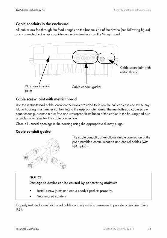
Cable conduits in the enclosure.All cables are fed through the feed-troughs on the bottom side of the device (see following figure) and connected to the appropriate connection terminals on the Sunny Island.
Cable screw joint with metric threadUse the metric-thread cable screw connections provided to fasten the AC cables inside the Sunny Island housing in a manner conforming to the appropriate norms. The metric-thread cable screw connections guarantee a dust-free and waterproof installation of the cables in the housing and also provide strain relief for the cable connection.
Close all unused openings in the housing using the appropriate dummy plugs.
Cable conduit gasketThe cable conduit gasket allows simple connection of the pre-assembled communication and control cables (with RJ45 plugs).
Properly installed screw joints and cable conduit gaskets guarantee to provide protection rating IP54.
NOTICE!
Damage to device can be caused by penetrating moisture
• Install screw joints and cable conduit gaskets properly.
• Seal unused conduits.
Cable conduit gasket
Cable screw joint with metric thread
DC cable insertion point

Sunny Island Electrical Connection SMA Solar Technology AG
42 SI2012_2224-TEN082311 Technical Description
Obtain an overview of the different components and connection areas of the Sunny Island (see section 7.1 "At a Glance" (Page 40)).
Detailed installation descriptions of the connections are provided in the following sections:
- DC connection Chapter 7.2 "DC connection" (Page 43)
- AC connection Chapter 7.3 "AC Connection" (Page 46)
- Grounding: Chapter 7.3.1 "Grounding" (Page 47)
- Sunny Remote Control 1 Chapter 7.4 "Sunny Remote Control 1" (Page 51)
- External communication: Chapter 7.5 "Communication" (Page 53)
- Battery temperature sensor: Chapter 7.6.1 "Battery Temperature Sensor" (Page 59)
- Multi-function Relays 1 and 2 Chapter 7.6.3 "Multi-function Relays 1 and 2" (Page 63)

SMA Solar Technology AG Sunny Island Electrical Connection
Technical Description SI2012_2224-TEN082311 43
7.2 DC connection
7.2.1 Grounding
Calculating the Required Grounding Conductor Cross-SectionThe SMA Solar Technology AG cannot state generally valid values for the cross-section of the conductor required for the external grounding of the battery. The conductor dimensions depend on the type and size of the battery connected, the external fuse (DC side) and the material used for the grounding conductor.
The required cross-section of a (copper) grounding conductor can be calculated using the following formula. Trigger times, e.g., for the integrated DC circuit breaker and short-circuit currents of between 2000 and 10,000, are typically about 25 ms.
WARNING!
The Sunny Island 2012 / 2224 has no internal DC fuse.
Install an external DC fuse between the Sunny Island and the battery as a protective conductor. Dimension the fuse in proportion to the cable cross-section used.
• Sunny Island 2012: fuse NH01, 250 A (BATFUSE-B.0x)
• Sunny Island 2224: fuse NH00, 125 A (BATFUSE-A.0x)
External grounding.
• External grounding of the negative pole of the batteries is possible, because the batteries and the grid side are galvanically isolated within the Sunny Island. In this case, make sure that the high currents that may occur under fault conditions can be adequately diverted.
• If a connection is required, then this must be made separately, external to the Sunny Island, by an installer.
• When grounding the battery, the Sunny Island's enclosure must be additionally grounded, also in the DC area (see chapter 7.3.1 "Grounding" (Page 47)).
Determining the wire cross-section
Exact calculation of the grounding conductor cross-section must consider the regionally applicable standards and guidelines (e.g., DIN VDE 0100 Part 540).
Sunny Island Electrical Connection SMA Solar Technology AG
44 SI2012_2224-TEN082311 Technical Description
A grounding conductor of 10,000 mm² cross-section is thus adequate for short-circuit currents up to 16 A.
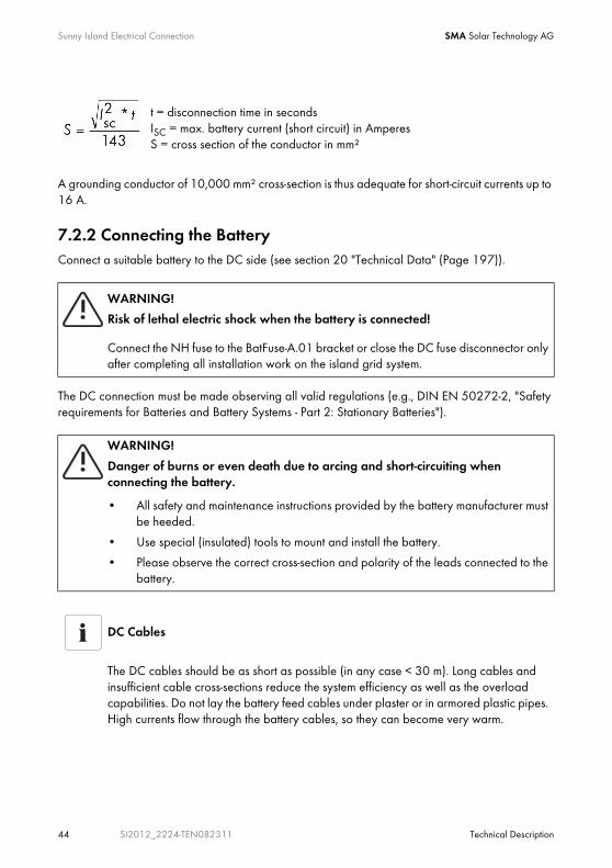
7.2.2 Connecting the BatteryConnect a suitable battery to the DC side (see section 20 "Technical Data" (Page 197)).
The DC connection must be made observing all valid regulations (e.g., DIN EN 50272-2, "Safety requirements for Batteries and Battery Systems - Part 2: Stationary Batteries").
WARNING!
Risk of lethal electric shock when the battery is connected!
Connect the NH fuse to the BatFuse-A.01 bracket or close the DC fuse disconnector only after completing all installation work on the island grid system.
WARNING!
Danger of burns or even death due to arcing and short-circuiting when connecting the battery.
• All safety and maintenance instructions provided by the battery manufacturer must be heeded.
• Use special (insulated) tools to mount and install the battery.
• Please observe the correct cross-section and polarity of the leads connected to the battery.
DC Cables
The DC cables should be as short as possible (in any case < 30 m). Long cables and insufficient cable cross-sections reduce the system efficiency as well as the overload capabilities. Do not lay the battery feed cables under plaster or in armored plastic pipes. High currents flow through the battery cables, so they can become very warm.
t = disconnection time in secondsISC = max. battery current (short circuit) in AmperesS = cross section of the conductor in mm²
SMA Solar Technology AG Sunny Island Electrical Connection
Technical Description SI2012_2224-TEN082311 45
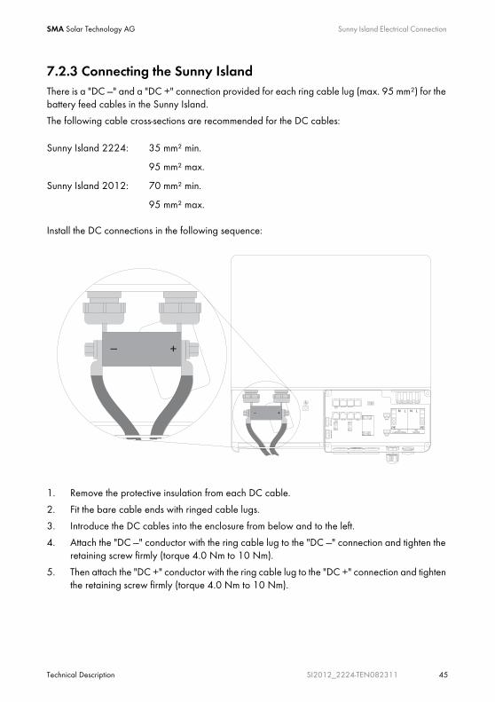
7.2.3 Connecting the Sunny IslandThere is a "DC —" and a "DC +" connection provided for each ring cable lug (max. 95 mm²) for the battery feed cables in the Sunny Island.
The following cable cross-sections are recommended for the DC cables:
Install the DC connections in the following sequence:
1. Remove the protective insulation from each DC cable.
2. Fit the bare cable ends with ringed cable lugs.
3. Introduce the DC cables into the enclosure from below and to the left.
4. Attach the "DC —" conductor with the ring cable lug to the "DC —" connection and tighten the retaining screw firmly (torque 4.0 Nm to 10 Nm).
5. Then attach the "DC +" conductor with the ring cable lug to the "DC +" connection and tighten the retaining screw firmly (torque 4.0 Nm to 10 Nm).
Sunny Island 2224: 35 mm² min.
95 mm² max.
Sunny Island 2012: 70 mm² min.
95 mm² max.
Sunny Island Electrical Connection SMA Solar Technology AG
46 SI2012_2224-TEN082311 Technical Description
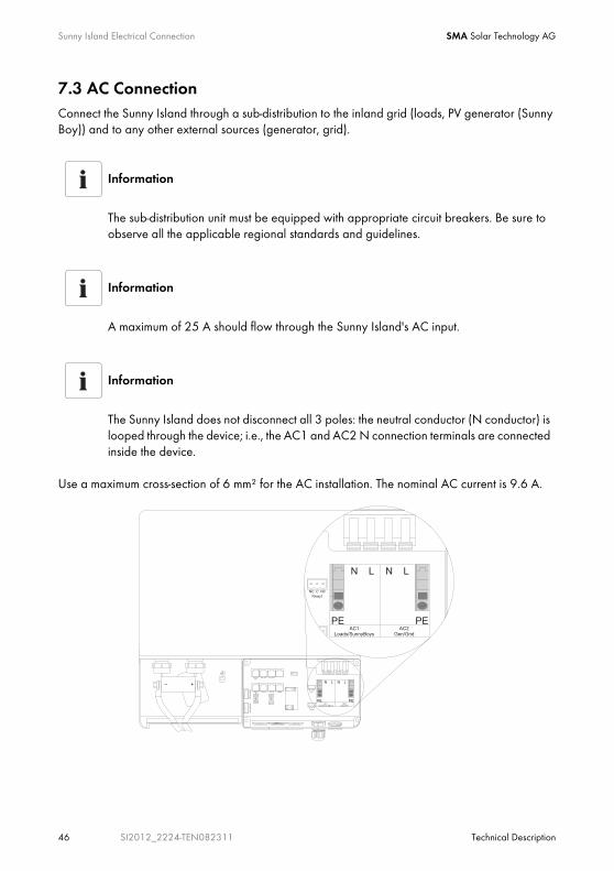
7.3 AC ConnectionConnect the Sunny Island through a sub-distribution to the inland grid (loads, PV generator (Sunny Boy)) and to any other external sources (generator, grid).
Use a maximum cross-section of 6 mm² for the AC installation. The nominal AC current is 9.6 A.
Information
The sub-distribution unit must be equipped with appropriate circuit breakers. Be sure to observe all the applicable regional standards and guidelines.
Information
A maximum of 25 A should flow through the Sunny Island's AC input.
Information
The Sunny Island does not disconnect all 3 poles: the neutral conductor (N conductor) is looped through the device; i.e., the AC1 and AC2 N connection terminals are connected inside the device.

SMA Solar Technology AG Sunny Island Electrical Connection
Technical Description SI2012_2224-TEN082311 47
7.3.1 Grounding
For the ground connection with two redundant protective leads use the PE connections in the AC connection area of the Sunny Island.
For the ground connection with the protective lead of > 10 mm² use the addtional PE connection (PE crown on the enclosure) in the DC connection area (see following segment).
Additional Grounding of the Housing.If the Sunny Island is used in a country which prescribes the use of a second protective ground (e.g., Switzerland), you can ground the enclosure additionally by using the PE crown in the DC connection area.
Proceed as follows:
1. Strip the protective conductor.
2. Fit the protective conductor with a ringed cable lug (max. cross-section 50 mm²).
3. Screw the ringed cable lug onto the enclosure's PE crown (screw: M8 x 20 mm).
Information
In stand-alone configurations, the (protective) ground of the Sunny Island and its individual components must be wired as a TN grid only. All valid standards and guidelines must be taken into account!
CAUTION!
Danger of injury due to leakage current against PE.
The N connection of the Sunny Island has NOT been connected with PE by default.
• Ground the island grid system outside the Sunny Island before commissioning (see chapter 7.3.3 "AC2 (Gen/Grid)" (Page 50)).
• For safety technical reasons (leakage currents of over 3.5 mA),
- two protective ground wires with 6 mm² (double ground) or
- one protective ground wire >10 mm².

Sunny Island Electrical Connection SMA Solar Technology AG
48 SI2012_2224-TEN082311 Technical Description
7.3.2 AC1 (Loads/Sunny Boys)Connect, with three conductors via the subdistribution, for example, loads, PV generators (Sunny Boy) and wind power plants (Windy Boy), to the Sunny Island's AC1 connection.
Connection procedure for the Sunny Island:
1. Loosen the metric-threaded cable screw joint on the right of the enclosure's underside.
2. Insert the 3-conductor cable through the threaded joint.
3. Draw the cable into the enclosure.
4. Flip the AC1's terminal connectors (N and L conductors) all the way up.
5. Remove the protective insulation from each of the three wires.
DANGER!
Death hazard due to residual currents
• Install an RCD circuit breaker between the Sunny Island and the loads.
DANGER!
Risk of lethal electric shock
Improperly laid cables can loosen out of the terminal connectors.
• Do not use end wire sleeves when connecting the AC cable.
SMA Solar Technology AG Sunny Island Electrical Connection
Technical Description SI2012_2224-TEN082311 49
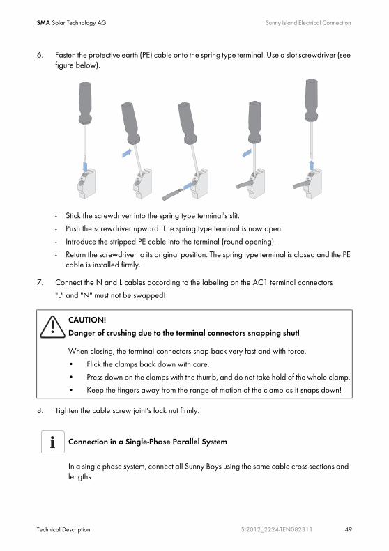
6. Fasten the protective earth (PE) cable onto the spring type terminal. Use a slot screwdriver (see figure below).
- Stick the screwdriver into the spring type terminal's slit.
- Push the screwdriver upward. The spring type terminal is now open.
- Introduce the stripped PE cable into the terminal (round opening).
- Return the screwdriver to its original position. The spring type terminal is closed and the PE cable is installed firmly.
7. Connect the N and L cables according to the labeling on the AC1 terminal connectors
"L" and "N" must not be swapped!
8. Tighten the cable screw joint's lock nut firmly.
CAUTION!
Danger of crushing due to the terminal connectors snapping shut!
When closing, the terminal connectors snap back very fast and with force.
• Flick the clamps back down with care.
• Press down on the clamps with the thumb, and do not take hold of the whole clamp.
• Keep the fingers away from the range of motion of the clamp as it snaps down!
Connection in a Single-Phase Parallel System
In a single phase system, connect all Sunny Boys using the same cable cross-sections and lengths.

Sunny Island Electrical Connection SMA Solar Technology AG
50 SI2012_2224-TEN082311 Technical Description
7.3.3 AC2 (Gen/Grid)Via the distribution, connect the generator or the public grid using 3 conductors to the Sunny Island's AC2 connector.
Proceed as follows:
1. Remove the blank seals from the opening on the underside of the enclosure and to the right.
2. Introduce the metric-threaded cable connection M25 (included in the delivery) into the opening and tighten.
Do not forget the seal!
3. Wire up the AC2 cable as described in chapter 7.3.2 "AC1 (Loads/Sunny Boys)" (Page 48).
Connection in a 3-Phase System
• In a 3-phase system, always connect the master to phase L1, slave 1 to phase L2 and slave 2 to phase L3. This circuitry results in a right rotating field.
• If a phase fails within a three-phase grid, the cluster continues to run. In order to protect your loads, you may require phase monitoring or a motor overload switch.
DANGER!
Death hazard due to residual current if the neutral wire is not grounded.
• Do not install an RCD circuit breaker (or similar) onto the island grid system's grid-side supply cable.
• Ground the grid-side PEN conductor within the installation (before or at the separation into N and PE conductors, e.g., the connection from the house's junction box to the equipotential bonding rail).
Connection in a Single-Phase Parallel System
• In single-phase parallel systems, connect each of the Sunny Islands via the AC2 terminal to the generator or the public grid.
• The cable cross-sections and cable lengths used must be identical.

SMA Solar Technology AG Sunny Island Electrical Connection
Technical Description SI2012_2224-TEN082311 51
7.4 Sunny Remote Control 1
The Sunny Remote Control 1 is connected to the "Display" terminal in the Sunny Island.
Connection in a 3-Phase System
• In a 3-phase system, always connect the master to phase L1, slave 1 to phase L2 and slave 2 to phase L3. This circuitry results in a right rotating field.
• The system does not monitor additional fuses. Check any additional fuses regularly!
NOTICE!
The components in the Sunny Island (e.g., communications interface) can be damaged by an electrostatic discharge!
• When working on the Sunny Island and when handling the components observe all ESD safety regulations.
• Eliminate static charge by touching the grounded metal casing.
• Only then should you begin any work.
Sunny Island Electrical Connection SMA Solar Technology AG
52 SI2012_2224-TEN082311 Technical Description
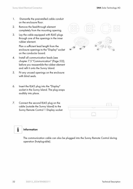
1. Dismantle the preinstalled cable conduit on the enclosure floor.
2. Remove the feed-through element completely from the mounting opening.
3. Lay the cable equipped with RJ45 plugs through one of the openings in the inner rubber element.
Plan a sufficient lead length from the enclosure openings to the "Display" socket on the conductor board.
4. Install all communication leads (see chapter 7.5 "Communication" (Page 53)), before you reassemble the rubber element and refit it onto the Sunny Island.
5. Fit any unused openings on the enclosure with blind seals.
6. Insert the RJ45 plug into the "Display" socket in the Sunny Island. The plug snaps audibly into place.
7. Connect the second RJ45 plug on the cable (outside the Sunny Island) to the Sunny Remote Control 1 Display socket.
Information
The communication cable can also be plugged into the Sunny Remote Control during operation (hotplug-able).
SMA Solar Technology AG Sunny Island Electrical Connection
Technical Description SI2012_2224-TEN082311 53
7.5 Communication
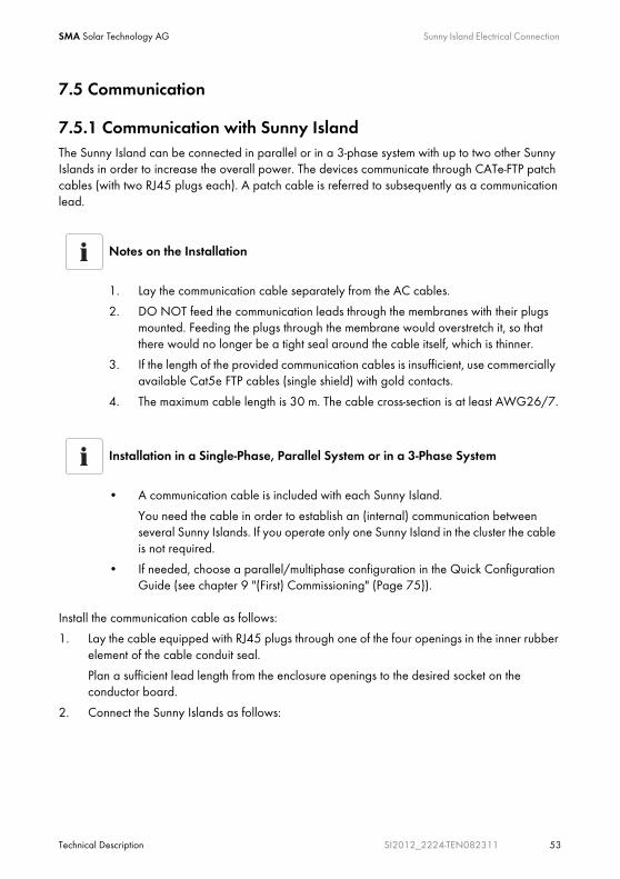
7.5.1 Communication with Sunny IslandThe Sunny Island can be connected in parallel or in a 3-phase system with up to two other Sunny Islands in order to increase the overall power. The devices communicate through CATe-FTP patch cables (with two RJ45 plugs each). A patch cable is referred to subsequently as a communication lead.
Install the communication cable as follows:
1. Lay the cable equipped with RJ45 plugs through one of the four openings in the inner rubber element of the cable conduit seal.
Plan a sufficient lead length from the enclosure openings to the desired socket on the conductor board.
2. Connect the Sunny Islands as follows:
Notes on the Installation
1. Lay the communication cable separately from the AC cables.
2. DO NOT feed the communication leads through the membranes with their plugs mounted. Feeding the plugs through the membrane would overstretch it, so that there would no longer be a tight seal around the cable itself, which is thinner.
3. If the length of the provided communication cables is insufficient, use commercially available Cat5e FTP cables (single shield) with gold contacts.
4. The maximum cable length is 30 m. The cable cross-section is at least AWG26/7.
Installation in a Single-Phase, Parallel System or in a 3-Phase System
• A communication cable is included with each Sunny Island.
You need the cable in order to establish an (internal) communication between several Sunny Islands. If you operate only one Sunny Island in the cluster the cable is not required.
• If needed, choose a parallel/multiphase configuration in the Quick Configuration Guide (see chapter 9 "(First) Commissioning" (Page 75)).

Sunny Island Electrical Connection SMA Solar Technology AG
54 SI2012_2224-TEN082311 Technical Description
Upon delivery of a Sunny Island, the "SyncIn" socket is terminated.
- Master (first Sunny Island):
- A terminator is plugged into the "SyncIn" socket.
- Insert the communication cable's RJ45 plug in the "SyncOut" socket. The plug snaps audibly into place.
- Lay the other end of the communication cable in the second Sunny Island.
- Slave 1 (second Sunny Island):
- Remove the terminator from the "SyncIn" socket.
- Plug the RJ45 plug of the communication cable from the master device in the "SyncIn" socket of the slave 1. The plug snaps audibly into place.
- If no other Sunny Island (slave 2) is to be installed in the island grid system, plug a terminator in the "SyncOut" socket of the slave 1. The terminator snaps audibly into place.
- If a third Sunny Island (slave 2) is to be installed in the island grid system, plug the RJ45 plug of another communication cable in the slave 1's "SyncOut" socket. The plug snaps audibly into place.
- Lay the other end of the communication cable in the third Sunny Island.

SMA Solar Technology AG Sunny Island Electrical Connection
Technical Description SI2012_2224-TEN082311 55
- Slave 2 (third Sunny Island):
- Remove the terminator from the "SyncIn" socket.
- Plug the RJ45 plug of the communication cable from the slave 1 device in the "SyncIn" socket of the slave 2. The plug snaps audibly into place.
- Plug a terminator in the "SyncOut" socket of the slave 2. The terminator snaps audibly into place.
3. Install all communication leads before you reassemble the rubber element and conduit and refit them onto the Sunny Island.
4. Fit any unused openings on the enclosure with blind seals.
Please Note
The first and last Sunny Islands in a chain must always be terminated.
Information
The "SysCanOut" and "SysCanIn" sockets have no function.
Sunny Island Electrical Connection SMA Solar Technology AG
56 SI2012_2224-TEN082311 Technical Description
7.5.2 Communication With External DevicesYou can connect SMA communication devices (e.g., Sunny Boy Control, Sunny WebBox) or a PC with the appropriate software to a communication interface. A detailed wiring diagram can be found in the communication device manual, the software, or on the Internet at www.SMA.de.
This wiring diagram includes:
• Details on the required cable type
• Which of the Sunny Island's connections are used
• Whether or not the communications cables must be terminated
• Whether the PE needs to be connected to the cable shield
You can incorporate an RS485 communication interface into the Sunny Island.
Information
Communication via Powerline/Powerline modem (NLM) is not possible in an island grid system.
NOTICE!
Electrostatic discharges may damage the communications interface.
• When working on the Sunny Island and when handling the components observe all ESD safety regulations.
• Eliminate static charge by touching the grounded metal casing.
• Only then should you begin any work.

SMA Solar Technology AG Sunny Island Electrical Connection
Technical Description SI2012_2224-TEN082311 57
When installing the communications interface proceed as follows:
1. Lay the interface's communication cable in one of the free openings of the cable conduit seal's inner rubber element.
Plan a sufficient lead length from the enclosure opening to the "ComOut" socket on the conductor board in the Sunny Island.
2. Introduce the communication cable into the enclosure from outside.
3. Insert the RJ45 plug into the "ComOut" socket in the Sunny Island. The plug snaps audibly into place.
4. Reassemble the cable conduit unit and reinsert it into the opening on the floor of the Sunny Island.
5. Fit any unused openings on the enclosure with blind seals.
6. Connect the other end of the communication cable to the communication device.
Find the description of which three pins you should use in the installation instructions of the communication device.
The following table shows the allocation of these pins to the corresponding pins of the RJ45 socket.
7. Terminating the Sunny Island using RS485.
The RS485 data bus of Sunny Island is terminated with a plug. This plug is already pre-installed in your Sunny Island. Remove this plug only if you intend to connect another communication device.
8. Plug the communications interface into the board.
WebBox Pin Assignment RS485 RJ45 Socket
2 A (Data+) 3
7 B (Data-) 6
5 GND 2
Interface port(Piggy Back) RS485

Sunny Island Electrical Connection SMA Solar Technology AG
58 SI2012_2224-TEN082311 Technical Description
The Sunny Island can be operated at different transmission rates (1200 to 19200 bps), to communicate with external devices. The parameter "250.06 ComBaud" must be set correspondingly.
The Sunny Island uses the SMA-Net protocol for communication.
Setting the Baudrate
If Sunny Boys are connected to the communications bus, then the baud rate must be set to 1200 bps (factory setting).
SMA Solar Technology AG Sunny Island Electrical Connection
Technical Description SI2012_2224-TEN082311 59
7.6 Additional Connections
7.6.1 Battery Temperature SensorThe battery temperature sensor measures the temperature of the connected battery. This is necessary since the optimum charging voltage for a battery largely depends on the temperature. Further information is provided in section 12.4 "Charge Control" (Page 122). A battery temperature sensor is provided with the Sunny Island (see the delivery scope description).
Defective Battery Temperature Sensor
If the battery temperature sensor is rendered inoperative, e.g., due to a short circuit or broken cable, the Sunny Island works with a fixed setting which, however, leads to an insufficient charge of the battery in the long run. In this case the Sunny Island's display shows a warning.
• Replace the defective battery temperature sensor promptly.
• Always operate the Sunny Island with the battery temperature sensor (included in the delivery).
NOTICE!
Damage to the battery due to faulty installation
• Always install the battery temperature sensor included in the delivery.
• Do not drill holes into the battery when installing the battery temperature sensor.
- Fasten the battery temperature sensor to the outside of one of the battery cells.
- Choose a position in the space between two cells or in the middle area of the battery bank, where the heat generation during operation is greatest.
One battery temperature sensor per cluster!
A battery temperature sensor is provided with each Sunny Island.
Only one battery temperature sensor, which is connected to the corresponding master, is required for a cluster.
Sunny Island Electrical Connection SMA Solar Technology AG
60 SI2012_2224-TEN082311 Technical Description
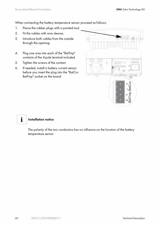
When connecting the battery temperature sensor proceed as follows:
1. Pierce the rubber plugs with a pointed tool.
2. Fit the cables with wire sleeves.
3. Introduce both cables from the outside through the opening.
4. Plug one wire into each of the "BatTmp" contacts of the 4-pole terminal included.
5. Tighten the screws of the contact.
6. If needed, install a battery current sensor before you insert the plug into the "BatCur BatTmp" socket on the board.
Installation notice
The polarity of the two conductors has no influence on the function of the battery temperature sensor.
SMA Solar Technology AG Sunny Island Electrical Connection
Technical Description SI2012_2224-TEN082311 61
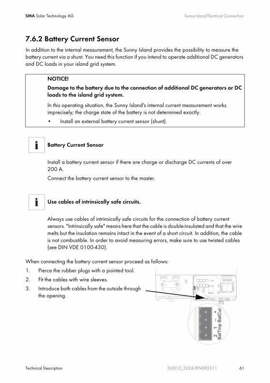
7.6.2 Battery Current SensorIn addition to the internal measurement, the Sunny Island provides the possibility to measure the battery current via a shunt. You need this function if you intend to operate additional DC generators and DC loads in your island grid system.
When connecting the battery current sensor proceed as follows:
1. Pierce the rubber plugs with a pointed tool.
2. Fit the cables with wire sleeves.
3. Introduce both cables from the outside through the opening.
NOTICE!
Damage to the battery due to the connection of additional DC generators or DC loads to the island grid system.
In this operating situation, the Sunny Island's internal current measurement works imprecisely; the charge state of the battery is not determined exactly.
• Install an external battery current sensor (shunt).
Battery Current Sensor
Install a battery current sensor if there are charge or discharge DC currents of over 200 A.
Connect the battery current sensor to the master.
Use cables of intrinsically safe circuits.
Always use cables of intrinsically safe circuits for the connection of battery current sensors. "Intrinsically safe" means here that the cable is double-insulated and that the wire melts but the insulation remains intact in the event of a short circuit. In addition, the cable is not combustible. In order to avoid measuring errors, make sure to use twisted cables (see DIN VDE 0100-430).
Sunny Island Electrical Connection SMA Solar Technology AG
62 SI2012_2224-TEN082311 Technical Description
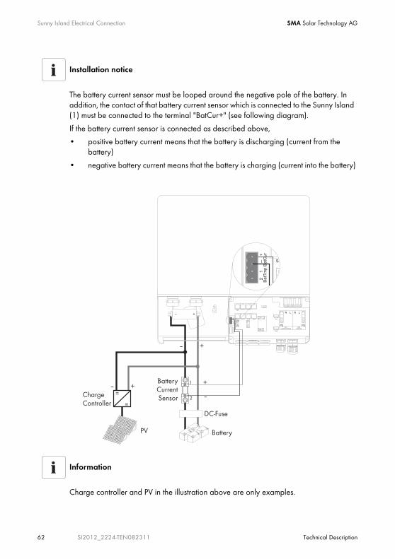
Installation notice
The battery current sensor must be looped around the negative pole of the battery. In addition, the contact of that battery current sensor which is connected to the Sunny Island (1) must be connected to the terminal "BatCur+" (see following diagram).
If the battery current sensor is connected as described above,
• positive battery current means that the battery is discharging (current from the battery)
• negative battery current means that the battery is charging (current into the battery)
Information
Charge controller and PV in the illustration above are only examples.
SMA Solar Technology AG Sunny Island Electrical Connection
Technical Description SI2012_2224-TEN082311 63
4. Plug one wire into each of the "BatCur" contacts of the 4-pole terminal included.
5. Tighten the screws of the contact.
Observe the correct polarity of the leads (see also the installation notice above).
6. Insert the plug into the "BatCur BatTmp" socket on the board.
7.6.3 Multi-function Relays 1 and 2
The Sunny Island offers you several options for the control of internal and external processes. To this end, the device is equipped with two multi-function relays to which you can assign functions with the parameters "241.01 Rly1Op" and "241.02 Rly2Op" (see chapter 14 "Relay" (Page 152)).
Commissioning the Battery Temperature Sensor
When connecting the battery temperature sensor, set up the internal offset on the Sunny Island during the first commissioning of the island grid system (see chapter 9.3 "Commissioning the Battery Current Sensor" (Page 81)).
DANGER!
Death hazard due to faulty insulation
Separate the relay cable safely away from the communication area.
• Strip the wires of the relay cable.
• Fit each individual wire with the silicon tube included in the delivery.
• The device should not be operated without the silicon tube.
Information
The slave devices' relays can also be used and programmed separately.
Information on the switching capacity of the relays is provided in section 20 "Technical Data" (Page 197).

Sunny Island Electrical Connection SMA Solar Technology AG
64 SI2012_2224-TEN082311 Technical Description
Proceed as follows when installing the relay connections:
1. Pierce the rubber plugs with a pointed tool.
2. Fit the cables with wire sleeves.
3. Introduce both cables from the outside through the opening.
4. Insert the wires in the "Relay1" or "Relay2" sockets of the 3-pole terminal clamps provided.
5. Tighten the screws on the sockets.
6. Pay attention to the designation of the pins:
- NC: Normally closed (closed when idle)
- C: Contact (operation contact)
- NO: Normally opened (opened in standby)
7. Insert the plug into the appropriate socket on the board.
Operating principles of the relays
The relays are changeover contacts; they can be used as normally closed contacts (NCC) or as normally open contacts (NOC).
The relay functions are listed as NO contact functions, in other words, the contact is closed if the relay is activated by selecting the function. An exception is "Alm" (alarm), in which case the relay has a break function. This means that the relay is normally activated, opening the contact. Only in case of a failure is it deactivated and closes the contact (activating, for example, a warning light).
Please note:
You can only assign one function to the relay.
NC
NO
C
SMA Solar Technology AG Sunny Island Electrical Connection
Technical Description SI2012_2224-TEN082311 65
Load sheddingThe Sunny Island can automatically switch off loads to protect the batteries from deep discharge. To do this, an external (AC or DC) power contactor must be installed between the Sunny Island and the loads (see also chapter 19.3 "Accessories (Optional)" (Page 195)).
Generator StartThe Sunny Island can control generators. It supports generators that can be started and stopped by a single contact and generators that require more than one contact (in combination with the optionally available generator manager (GenMan)).
NOTICE!
If a relay is used for load shedding, the loads connected to the power contactor will no longer be supplied with electricity in the event of a fault in the island grid system, even when the grid is available.
Default Setting of the Relays
By default, relay 1 is set to the start generator function "AutoGn" and relay 2 is set to the load shed function "AutoLodSoc".
The first figure in section 2 "System Overview" (Page 12) shows the principal connection.

Sunny Island Electrical Connection SMA Solar Technology AG
66 SI2012_2224-TEN082311 Technical Description
7.6.4 BatVtgOut Power Supply The battery voltage is conducted to the outside at these terminals. It is fused at both poles by PTC thermistors (max. 0.75 A) and can fluctuate depending on the battery status. This connection can, for example, be used to supply a DC contactor for load shedding.
Proceed as follows when connecting the power supply:
1. Pierce the rubber plugs with a pointed tool.
2. Fit the cables with wire sleeves.
3. Introduce both cables from the outside through the opening.
4. Plug one wire into each of the "BatVtgOut" contacts of the 4-pole terminal included.
5. Tighten the screws of the contact.
6. If needed, install DigIn before you insert the plug into the "DigIn BatVtgOut" socket on the board.
7.6.5 DigIn Digital InputThese terminals function as a digital input for external electric sources. For example, the feedback contact for the GenMan (GenRn) is connected here.
Information
If you connect a GenMan, or operate the system with the generator and utility (GenGD) in parallel, use the relays on the master device in order to activate the respective functions.

SMA Solar Technology AG Sunny Island Electrical Connection
Technical Description SI2012_2224-TEN082311 67
Proceed as follows when connecting the digital input:
1. Pierce the rubber plugs with a pointed tool.
2. Fit the cables with wire sleeves.
3. Introduce both cables from the outside through the opening.
4. Plug one wire into each of the "DigIn" contacts of the 4-pole terminal included.
5. Tighten the screws of the contact.
6. Insert the plug into the "DigIn BatVtgOut" socket on the board.
Further Information
For further information on connecting and operating the GenMan see the respective product documentation.

Sunny Island Electrical Connection SMA Solar Technology AG
68 SI2012_2224-TEN082311 Technical Description
7.7 Configuring a System with Several Sunny Islands1)
The Sunny Island can be configured for various system combinations:
• Single-phase system with one Sunny Island
• Single-phase system witn two or three Sunny Islands connected in parallel
• 3-phase system with three Sunny Islands (one Sunny Island per phase)
Carry out the configuration before the first commissioning of the system. Each Sunny Island must be configured with the aid of the rotary code switch. Upon delivery this rotary code switch is set to "0".
The rotary code switch is found on the back of the back of the display, on the inside of the lower enclosure cover of the Sunny Island.
To configure the system proceed as follows:
With a screwdriver (2.5 mm), turn the mark on the rotary code switch to the desired position.
Set the rotary code switch to
- 0 for master
- 1 for slave 1
- 2 for slave 2
1) These applications are only possible with firmware versions 3.0 and above.
Please note:
The position of the rotary code switch must only be changed if you intend to operate more than one Sunny Island in your system!

SMA Solar Technology AG Sunny Island Electrical Connection
Technical Description SI2012_2224-TEN082311 69
The configuration possibilities of the rotary code switch at a glance:
7.8 Concluding Tasks1. Remove all tools from the enclosure.
2. Have all cables been laid so as to be strain-relieved?
3. Are there no communication cables inside the Sunny Island which are touching a stripped 230 V wire?
4. Are all cable conduits on the Sunny Island sealed?
5. Have all unused openings been closed with blind seals?
6. Close the lower enclosure cover (see chapter 6.2 "Closing the Sunny Island" (Page 38)).
The installation of the Sunny Island and Sunny Remote Control 1 is complete.
Parameter Meaning
0 Master
1 Slave 1
2 Slave 2

Control Elements SMA Solar Technology AG
70 SI2012_2224-TEN082311 Technical Description
8 Control ElementsBefore commissioning the island grid system, familiarize yourself with the operation of the device.
The Sunny Island is operated with the control panel on the enclosure only under the standard setup (for default values see chapter 17.2 "Adjustable System Parameters" (Page 166)).
To change the Sunny Island's parameter setup you need the Sunny Remote Control 1 (SRC-1) external display.
8.1 Sunny Island
8.1.1 Control Panel on the EnclosureThe following diagram describes the elements of the control panel:
8.1.2 Control Panel ButtonsThe Sunny Island's control panel has three buttons.
• Start / Stop starts and stops the inverter operation of the Sunny Island (see also chapter 10.1 "Switching On and Off" (Page 83)).
• DC start turns ont the Sunny Island (standby).
• DC stop turns off the Sunny Island
8.1.3 Meaning of the Light-Emitting Diodes (LEDs)The three LEDs show, from top to bottom, state messages for
• Sunny Island (inverter LED)
• Grid / Generator (grid LED)
• Battery (battery LED)
Start / Stop button
DC start button
Inverter LED Battery LEDGrid LEDDC stop button

SMA Solar Technology AG Control Elements
Technical Description SI2012_2224-TEN082311 71
Depending on the message, the corresponding LED glows red, green, orange, or not at all.
The following table describes the meanings of the color signals from the inverter LED:
The following table describes the meanings of the color signals from the grid LED:
The following table describes the meanings of the color signals from the battery LED:
Green Red OrangeOperating mode of the Sunny Island
— — — Off (device has been switched off)
— — ON Standby (no inverter operation)
ON — — In operation
— ON — Failure or error
Green Red OrangeOperating modegrid/generator
— — — if applicable, no grid/generator(conduction possible)
— — ON Synchronization to the external grid / generator
ON — — Operation with grid / generator
— ON — Failure or error
Green Red Orange Battery charge level
— — — Off (device has been switched off)
ON — — 100 % — 50 %
— — ON 50 % — 20 %
— ON — 20 % — 0 %

Control Elements SMA Solar Technology AG
72 SI2012_2224-TEN082311 Technical Description
8.2 Sunny Remote Control 1
You can navigate the Sunny Island's menus with the external display (Sunny Remote Control 1).
The Sunny Remote Control 1 consists of
• Display
• Key
• rotating pushbutton
Information
The Sunny Island is controlled via the external display (Sunny Remote Control 1).
Display rotating push button
Key
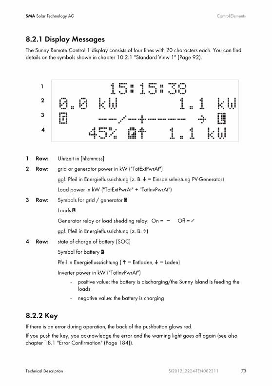
SMA Solar Technology AG Control Elements
Technical Description SI2012_2224-TEN082311 73
8.2.1 Display Messages The Sunny Remote Control 1 display consists of four lines with 20 characters each. You can find details on the symbols shown in chapter 10.2.1 "Standard View 1" (Page 92).
8.2.2 KeyIf there is an error during operation, the back of the pushbutton glows red.
If you push the key, you acknowledge the error and the warning light goes off again (see also chapter 18.1 "Error Confirmation" (Page 184)).
1 Row: Uhrzeit in [hh:mm:ss]
2 Row: grid or generator power in kW ("TotExtPwrAt")
ggf. Pfeil in Energieflussrichtung (z. B. Š = Einspeiseleistung PV-Generator)
Load power in kW ("TotExtPwrAt" + "TotInvPwrAt")
3 Row: Symbols for grid / generator
Loads
Generator relay or load shedding relay: On = - Off = /
ggf. Pfeil in Energieflussrichtung (z. B. ‡)
4 Row: state of charge of battery (SOC)
Symbol for battery
Pfeil in Energieflussrichtung ( ‰ = Entladen, Š = Laden)
Inverter power in kW ("TotInvPwrAt")
- positive value: the battery is discharging/the Sunny Island is feeding the loads
- negative value: the battery is charging
1
2
3
4
Control Elements SMA Solar Technology AG
74 SI2012_2224-TEN082311 Technical Description
8.2.3 Rotating PushbuttonThe Sunny Remote Control 1 is controlled via a rotating pushbutton. This pushbutton allows simple navigation of the Sunny Island menus (see chapter 10.2 "Navigation Area" (Page 89)).
The rotating pushbutton can be pushed or turned.
• Turn:
- Moves up and down the menu
- Entering values
• Push:
- Open/close menu
- Select/cancel function
- Select value
- Confirm entry
- Answers yes/no
- Starts the device (hold down the button while on standby)
- Stops the device (hold down the button during operation)
Operation of the Sunny Island with the Sunny Remote Control 1 using the rotating pushbutton is described in detail in chapter 10 "Operating the Sunny Island" (Page 83).
In the remainder of the manual, the "rotating pushbutton" will only be referred to as "button".
8.2.4 MMC/SD cardThe Sunny Remote Control 1 provides an MMC/SD card for firmware updates and as a service interface. For details, refer to section 10.4 "Saving Data onto a MMC/SD Card" (Page 107).
SMA Solar Technology AG (First) Commissioning
Technical Description SI2012_2224-TEN082311 75
9 (First) Commissioning
9.1 Requirements
The Quick Configuration Guide (QCG) allows you to quickly install and commission your island grid system.
• On the Sunny Island, choose one of the following positions:
- Start system
- New system
- New battery
• Set up the parameters of the desired system specifically.
Check the connections
Before starting the commissioning process, ensure that all electrical connections have the correct polarity and make sure that everything is connected according to the instructions in chapters 7 "Sunny Island Electrical Connection" (Page 39).
Always save data
Always use the MMC/SD card for saving data and events. This way, in case of a failure, the SMA Solar Technology AG can help you quickly.
QCG with Sunny Remote Control 1 only
You can read and set up lists of menus, parameters and errors only with the Sunny Remote Control 1!
You can start up the Sunny Island without an external display as well. In this case the Sunny Island works only with the default parameters (see chapter 8 "Control Elements" (Page 70)).

(First) Commissioning SMA Solar Technology AG
76 SI2012_2224-TEN082311 Technical Description
9.2 Starting the Quick Configuration Guide (QCG)
The QCG is automatically activated when the device is started for the first time. Please continue reading under point 7, otherwise follow this list.
Information
The QCG sets up all parameters values automatically. Reasonable operation is possible this way, with little manipulation.
1. Insert the NH fuse in the BatFuse or close the BatFuse's DC disconnector.
2. Start the Sunny Island.
Press the DC start key on the Sunny Island
3. The Sunny Island initiates the startup phase. Wait for the following displays to finish.
4. "To init system hold <Enter>" is displayed after the startup phase.
5. Press and hold the pushbutton on the Sunny Control 1.
During this procedure a bar appears on the display.
HSI2012BFSBOOT V1.002
SI2224
@SMA 2007
To init system
hold <Enter>

SMA Solar Technology AG (First) Commissioning
Technical Description SI2012_2224-TEN082311 77
6. When the bar on the display disappears and the Sunny Remote control emits a tone signal:
Let go of the Sunny Remote Control pushbutton.
7. You are now in the Quick Configuration Guide (QCG).
By turning the pushbutton you can now choose between the following options:
- "Start System" (if you have accidentally accessed the QCG and would only like to restart the system)
- "New Battery" (if you would like to change the main battery settings, but retain the system configuration)
- "New System" (if you would like to start a new system or perform changes to the system configuration)
"New Battery"
When you want to install a new battery in the island grid system, you need the "New Battery" option.
Only specific battery settings are reset and set to new values. The overall system settings are not affected.
001#01 ¿
Start Menu
Start System
001#01 ¿
Start Menu
New Battery
001#01 ¿
Start Menu
New System
(First) Commissioning SMA Solar Technology AG
78 SI2012_2224-TEN082311 Technical Description
The following parameters must be set when "New Battery" is selected:
(default setting shown in bold)
- Battery type: 002#05 BatTyp (VRLA, FLA, NiCd)
- Battery voltage: 002#06 BatVtgLst (22 V, 24 V in 2 V increments for FLA and VRLA, 21.6 V, 22.8 V, 24 V in 1.2 V increments for NiCd), 24 V Sunny Island 2224, 12 V Sunny Island 2012
- Nominal battery capacity: 002#07 BatCpyNom (100 Ah to 10000 Ah, preset 140 Ah for Sunny Island 2224, )
The following parameters must be set when "New System" is selected:
(default setting shown in bold)
- System configuration: 003#01 (selection see "Overview of System Configurations:" (Page 79)), presetting is "1phase 1SI"a)
- Voltage / Frequency type: 003#02 AcVtgFrqSet (230V_50Hz, 220V_60Hz)
- Date: 003#03 Dt (dd.mm.yyyy)
- Time: 003#04 Tm (hh:mm:ss)
- Battery type: 003#05 BatTyp (VRLA, FLA, NiCd)
- Battery voltage: 003#06 BatVtgLst (22 V, 24 V in 2 V increments for FLA and VRLA, 21.6 V, 22.8 V, 24 V in 1.2 V increments for NiCd), 24 V Sunny Island 2224, 12 V Sunny Island 2012
- Nominal battery capacity: 003#07 BatCpyNom (50 Ah bis 10000 Ah, 140 Ah)
- External power supply unit: 003#08 ExtSrc (PvOnly, Gen, Grid, GenGrid)
- Maximal grid current: 003#09 GdCurNom (0 to 25 A, 16 A)
- Maximal generator current: 003#10 GnCurNom (0 to 25 A, 16 A)
- Generator interface: 003#11 GnStrMod (Manual, GenMan, Autostart)
a) These applications are only possible with firmware versions 3.0 and above.

SMA Solar Technology AG (First) Commissioning
Technical Description SI2012_2224-TEN082311 79
Overview of System Configurations:2)
The system configuration is described extensively in chapter 7.7 "Configuring a System with Several Sunny Islands" (Page 68).
2) These applications are only possible with firmware versions 3.0 and above.
Displayed Text Meaning
1phase 1SI single-phase system, 1 Sunny Island
1phase 2SI single-phase system, 2 Sunny Islands
1phase 3SI single-phase system, 3 Sunny Islands
Three 3SI 3-phase system, 3 Sunny Islands
8. After entering the parameters, the following message appears on the display:
"Init Device OK
START?"
9. Confirm the question:
Press and hold the pushbutton on the Sunny Remote Control 1.
10. The following message appears:
„ST(A)NDBY: To Start INV(erter) hold <Enter>“
The QCG is complete.
To start the Sunny Island:
11. Press and hold the pushbutton on the Sunny Remote Control 1.
During this procedure a bar appears on the display.
12. When the bar on the display disappears and the Sunny Remote control emits a tone signal:
Let go of the Sunny Remote Control pushbutton.
13. The Sunny Island starts.
The Sunny Island is in operation.
Init Device OK
START?
STNDBY: To Start
INV hold <Enter>
(First) Commissioning SMA Solar Technology AG
80 SI2012_2224-TEN082311 Technical Description
If there is an error message
If the device displays an error message, this error must be fixed before the device can be put into operation. Use the information in section 18 "Troubleshooting/Problem Solving" (Page 184).
Parameter Lists
Further details concerning the modifiable parameters are found in chapter 17 "Parameter List Overview" (Page 160).
Note that you must first enter the installer password before some parameters can be changed (see section 10.3.2 "Setting the Installer Password" (Page 102)). In addition, some parameters can only be changed in standby mode (see section 10.1.2 "Stopping" (Page 85)).
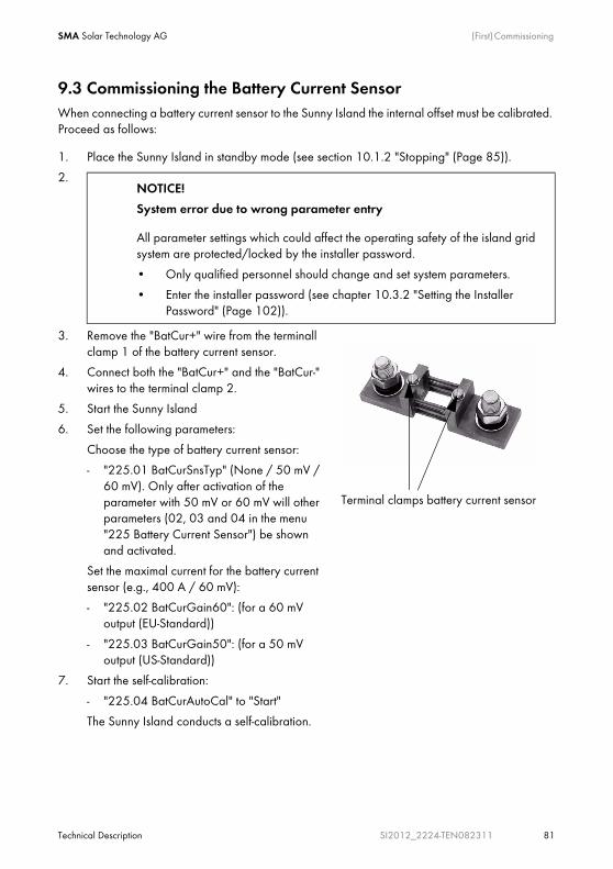
SMA Solar Technology AG (First) Commissioning
Technical Description SI2012_2224-TEN082311 81
9.3 Commissioning the Battery Current SensorWhen connecting a battery current sensor to the Sunny Island the internal offset must be calibrated. Proceed as follows:
1. Place the Sunny Island in standby mode (see section 10.1.2 "Stopping" (Page 85)).
2.
3. Remove the "BatCur+" wire from the terminall clamp 1 of the battery current sensor.
4. Connect both the "BatCur+" and the "BatCur-" wires to the terminal clamp 2.
5. Start the Sunny Island
6. Set the following parameters:
Choose the type of battery current sensor:
- "225.01 BatCurSnsTyp" (None / 50 mV / 60 mV). Only after activation of the parameter with 50 mV or 60 mV will other parameters (02, 03 and 04 in the menu "225 Battery Current Sensor") be shown and activated.
Set the maximal current for the battery current sensor (e.g., 400 A / 60 mV):
- "225.02 BatCurGain60": (for a 60 mV output (EU-Standard))
- "225.03 BatCurGain50": (for a 50 mV output (US-Standard))
7. Start the self-calibration:
- "225.04 BatCurAutoCal" to "Start"
The Sunny Island conducts a self-calibration.
NOTICE!
System error due to wrong parameter entry
All parameter settings which could affect the operating safety of the island grid system are protected/locked by the installer password.
• Only qualified personnel should change and set system parameters.
• Enter the installer password (see chapter 10.3.2 "Setting the Installer Password" (Page 102)).
Terminal clamps battery current sensor

(First) Commissioning SMA Solar Technology AG
82 SI2012_2224-TEN082311 Technical Description
8. Subsequently, check the offset error
"120.06 TotBatCur" should be (close to) zero
9. Switch off the Sunny Island and remove all voltages (see chapter 10.1 "Switching On and Off" (Page 83)).
10. Connect the "BatCur+" wire to the battery current sensor's terminal clamp 2 again.
Make sure the wires have the correct polarity.
- BatCur+ to terminal clamp 1
- BatCur- to terminal clamp 2
11. Start the Sunny Island (see chapter 10.1.1 "Switching On/Starting" (Page 83)).
12. Check the current direction: "120.06 TotBatCur"
Current direction
Battery discharge:
• no generator/grid connected
• Loads are being supplied
The value of the battery current is positive
Charging the battery
• Generator/grid connected
• Loads not being/being marginally supplied
• Battery is being charged
The value of the battery current is positive

SMA Solar Technology AG Operating the Sunny Island
Technical Description SI2012_2224-TEN082311 83
10 Operating the Sunny Island
10.1 Switching On and Off
10.1.1 Switching On/Starting
Start the island grid system with the Sunny Island
Proceed as follows:
1. Insert the NH fuse in the BatFuse or close the BatFuse's DC disconnector.
2. Press the DC start key on the Sunny Island
Wait approx. 20 to 30 seconds.
The Sunny Island is switched on
3. Press and hold the start / stop button on the Sunny Island.
During the start procedure the inverter LED goes from orange to green.
4. Let go of the start / stop button
The inverter LED glows green continually.
The Sunny Island is in operation.
WARNING!
Danger due to incorrect wiring of the island grid system
Only qualified electricians should carry out the first commissioning. Check the island grid system beforehand for
• correct electric cabling and connections
• voltages and polarities
Information
The island grid system can also be operated without an external display (Sunny Remote Control 1). In this case the Sunny Island works only with the default parameters (see chapter 17.2 "Adjustable System Parameters" (Page 166)).
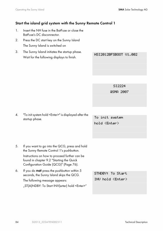
Operating the Sunny Island SMA Solar Technology AG
84 SI2012_2224-TEN082311 Technical Description
Start the island grid system with the Sunny Remote Control 1
1. Insert the NH fuse in the BatFuse or close the BatFuse's DC disconnector.
2. Press the DC start key on the Sunny Island
The Sunny Island is switched on
3. The Sunny Island initiates the startup phase.
Wait for the following displays to finish.
4. "To init system hold <Enter>" is displayed after the startup phase.
5. If you want to go into the QCG, press and hold the Sunny Remote Control 1's pushbutton.
Instructions on how to proceed further can be found in chapter 9.2 "Starting the Quick Configuration Guide (QCG)" (Page 76).
6. If you do not press the pushbutton within 5 seconds, the Sunny Island skips the QCG.
The following message appears:
„ST(A)NDBY: To Start INV(erter) hold <Enter>“
HSI2012BFSBOOT V1.002
SI2224
@SMA 2007
To init system
hold <Enter>
STNDBY: To Start
INV hold <Enter>

SMA Solar Technology AG Operating the Sunny Island
Technical Description SI2012_2224-TEN082311 85
10.1.2 StoppingStopping the system with the Sunny IslandSet the Sunny Island to standby.
Proceed as follows:
1. Press and hold the start / stop button on the Sunny Island until the inverter LED glows orange continuously.
During the stop procedure the LED goes from green to orange.
2. Let go of the start / stop button
The Sunny Island has stopped.
The device is now in standby mode.
7. Press and hold the pushbutton on the Sunny Remote Control 1.
8. The Sunny Remote Control 1 emits a tone.
9. The Sunny Island starts.
10. Let go of the pushbutton.
The Sunny Island is in operation.
Starting the Sunny Island automatically
Even if the "250.01 AutoStr" parameter is set, the Sunny Island must be manually started for inverter operation after each DC start once, each time the DC circuit breaker is started.
If there is an error message
If the device displays an error message, this error must be fixed before the device can be put into operation. Use the information in section 18 "Troubleshooting/Problem Solving" (Page 184).

Operating the Sunny Island SMA Solar Technology AG
86 SI2012_2224-TEN082311 Technical Description
Stopping the system with Sunny Remote Control 1Set the Sunny Island to standby using the external display.
Proceed as follows:
1. Press and hold the pushbutton on the Sunny Remote Control 1.
The following display appears:
2. Hold the pushbutton as long as the remaining time for the stop process is shown on the display as bars.
3. The display changes
4. Let go of the pushbutton.
5. The Sunny Island has stopped.
DANGER!
Death hazard due to high voltages
The island grid system is in "standby" operating modus!
• Do not open the device!
• Do not work on the island grid system!
There are still voltages present on the Sunny Island (DC and AC sides).
• Switch off the Sunny Island
• Disconnecting the Sunny Island from Voltage Sources
Consumption in standby mode
In standby mode the Sunny Island still requires about 6 W of power from the batteries.
Hold to stop...
¿¿¿¿¿¿¿¿¿¿¿¿¿¿¿¿
STNDBY: To Start
INV hold <Enter>

SMA Solar Technology AG Operating the Sunny Island
Technical Description SI2012_2224-TEN082311 87
10.1.3 Switching OffSwitch off the Sunny Island in the following way:
1. Disconnect all loads.
2. Place the in standby mode (see section 10.1.2 "Stopping" (Page 85)).
3. Press the DC stop key on the Sunny Island
The Sunny Island is switched off
10.1.4 Disconnecting the Device from Voltage Sources1. Switch off the Sunny Island (see chapter 10.1.3 "Switching Off" (Page 87)).
2. Remove the NH fuse from the BatFuse and/or open the BatFuse's DC disconnector.
The Sunny Island is disconnected from the battery
3. Separate the Sunny Island from all AC voltage sources.
4. Make sure that the Sunny Island has been disconnected securely from all voltage sources.
5. Wait at least 15 minutes.
The capacitors discharge and allow the voltage inside the device drops to a safe level.
6. The Sunny Island is now completely free of voltage.
7. You can now open the lower enclosure cover of the Sunny Island.
DANGER!
Death hazard due to high voltages
The island grid system is disconnected! There are still voltages present on the Sunny Island (DC and AC sides).
• Disconnecting the Sunny Island from Voltage Sources
Information
You can only ensure that all internal meter readings/values are saved by using this switching sequence.
Ensure that the device cannot be reconnected!
Wait 30 seconds before switching the device on again. Otherwise the smooth operation of the Sunny Island cannot be guaranteed.

Operating the Sunny Island SMA Solar Technology AG
88 SI2012_2224-TEN082311 Technical Description
10.1.5 Restarting the System after Automatic Shutdown
If the Sunny Island has swiched itself off due to batteries which are too deeply discharged, proceed as follows to restart:
1. Press the DC stop key on the Sunny Island
2. After waiting for a minute, switch on the Sunny Island.
Press the DC start key on the Sunny Island
3. Start the Sunny Island (see chapter 10.1.1 "Switching On/Starting" (Page 83)).
4. Monitor the Sunny Island connection in the charging process with the Sunny Remote Control 1.
5. Check that all other energy generators in the island grid system are working correctly.
NOTICE!
System shutdown due to, for example, wrong device settings
• Before and after recommissioning, inspect the whole island grid system for errors
- Wrong wiring?
- Have any components failed?
- Are there any wrong parameter settings on the Sunny Island?
• If applicable, clear the errors.
Wait!
Wait a minute before you restart the Sunny Island with the DC start key. The capacitors must discharge first.
Information
If, as in rare cases, it is not possible to restart after one minute, wait a little longer. Try again. A possible cause can be component tolerances.
Charging the battery
Once the system is switched on again, it is important that the batteries are charged. If the grid is available again, and/or the generator starts, the grid/generator will recharge the batteries after a few minutes.

SMA Solar Technology AG Operating the Sunny Island
Technical Description SI2012_2224-TEN082311 89
10.2 Navigation AreaThe navigation area comprises the home screen as well as the main menu items
• 100# Meters (display values)
• 200# Settings
• 300# Diagnosis
• 400# Failure/Event (lists)
• 500# Operation (functions during operation)
• 600# Direct Access
A main menu is subdivided into submenus.
From a submenu you can select another submenu or a parameter.
You can access the navigation area from two access levels:
• User level
• Installer level (only with password)
The menu items and parameters which allow the editing of system parameters are accessible after entering the installer password (see chapter 10.3.2 "Setting the Installer Password" (Page 102)).
If Sunny Island begins to operate in battery-preservation mode, disconnect the loads!
If the Sunny Island enters the battery-preservation mode immediately after restarting see chapter 12.5 "Battery Preservation Mode" (Page 127).
• Verify the availability of the grid.
• Reconnect the loads again only after the Sunny Island is operating in charge mode.
NOTICE!
Damage to the system due to wrong parameter entry
• Only qualified personnel should change and set system parameters.
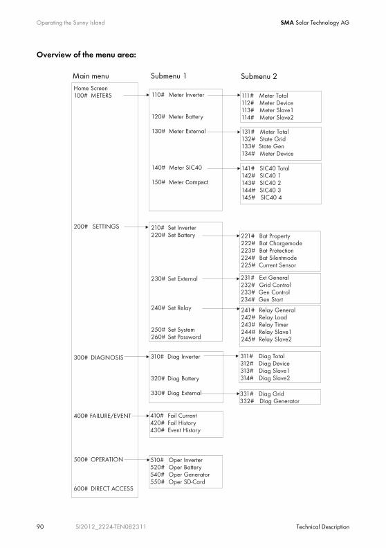
Operating the Sunny Island SMA Solar Technology AG
90 SI2012_2224-TEN082311 Technical Description
Overview of the menu area:
Main menu Submenu 1 Submenu 2
SMA Solar Technology AG Operating the Sunny Island
Technical Description SI2012_2224-TEN082311 91
100# Meters (display values): In this main menu you can find the displayed values of the following components of the island grid system:
• 110# Meter Inverter - Sunny Island
• 120# Meter Battery
• 130# Meter External - grid/generator
• 140# Meter SIC40 - battery charge regulator
• 150# Meter Compact - compact display of the commissioning values
By opening the corresponding submenus or the second tier of submenus, you can see the parameters (for example, Parameter "112.03 InvVtg").
200# Settings: In the following submenus you can see and edit the system parameters:
• 210# Set Inverter
• 220# Set Battery
• 230# Set External - grid/generator
• 240# Set Relay
• 250# Set System
• 260# Set Password
300# Diagnosis: In the following submenus you can see the system data:
• 310# Diag Inverter - device data (Sunny Island)
• 320# Diag Battery - battery data
• 330# Diag External - grid/generator
400# History: In the following submenus you can see various error and event lists:
• 410# Fail Current - present errors
• 420# Fail History - warnings and errors to date
• 430# Event History
500# Operation - functions during operation: In the following submenus you can see and edit the operating parameters:
• 510# Oper Inverter
• 520# Oper Battery
• 540# Oper Generator
• 550# Oper SD Card - MMC/SD card
600# Direct Access: In this main menu you can access settings and display values directly (see chapter 10.3.3 "Accessing Parameters Directly" (Page 105)).

Operating the Sunny Island SMA Solar Technology AG
92 SI2012_2224-TEN082311 Technical Description
10.2.1 Standard View 1The standard view 1 (home screen) shows the operating states of the Sunny Island:
1 Row: Uhrzeit in [hh:mm:ss]
2 Row: grid or generator power in kW ("TotExtPwrAt")
ggf. Pfeil in Energieflussrichtung (z. B. Š = Einspeiseleistung PV-Generator)
Load power in kW ("TotExtPwrAt" + "TotInvPwrAt")
3 Row: Symbols for grid / generator
Loads
Generator relay or load shedding relay: On = - Off = /
ggf. Pfeil in Energieflussrichtung (z. B. ‡)
4 Row: state of charge of battery (SOC)
Symbol for battery
Pfeil in Energieflussrichtung ( ‰ = Entladen, Š = Laden)
Inverter power in kW ("TotInvPwrAt")
- positive value: the battery is discharging/the Sunny Island is feeding the loads
- negative value: the battery is charging
1
2
3
4

SMA Solar Technology AG Operating the Sunny Island
Technical Description SI2012_2224-TEN082311 93
10.2.2 Standard View 2The standard view 2 shows the operating states of the Sunny Island:
• Battery charge power
• Output power
• Power from the grid/generator
as well as various information items on the status line.
A Battery charge level in [%]
B Output power of consumers in [kW]
C Power drawn from the grid/generator (AC2) in [kW]
D Device hierarchy (master, slave 1, slave 2)
E grid/generator limits
F MMC/SD card in use
G Direction of energy flow and system status
H Status of grid/generator (alternates with GenReq)
I Relay 1 Status
J Relay 2 Status
K Warning message
BA
GD KE
C
F H I J

Operating the Sunny Island SMA Solar Technology AG
94 SI2012_2224-TEN082311 Technical Description
Row 1
The bar shows the charge state of the battery in [%]
The value of the charge state is also shown digitally on the right.
Row 2
The bar shows the magnitude of the totall output power in [kW] with which the consumers are being supplied.
The arrow to the right, next to the describes the direction of energy flow:
• ‡ Loads are being supplied
• † Sunny Boy (PV inverter) feeds into the grid
The magnitude of the total output power [kW] is also shown to the right digitally.
Row 3
The bar shows the magnitude of the power drawn fromt the grid/generator in [kW].
The arrow to the right, next to the describes the direction of energy flow:
• ‡ The island grid system is being supplied by the grid/generator
The magnitude of the total power [kW] is also shown to the right digitally.
Row 4 (status bar)
The following information is shown in the status bar (from left to right):
1. Device hierarchy
• M1 = Master
• S1 = Slave1
• S2 = Slave2
[¿¿¿¿¿ ] 50%
‡[¿¿¿¿ ] 1.0kW
M1 ¿ ‡ ‡ * oo !
‡[¿¿¿¿¿¿¿¿¿ ] 1.9kW
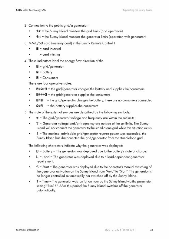
SMA Solar Technology AG Operating the Sunny Island
Technical Description SI2012_2224-TEN082311 95
2. Connection to the public grid/a generator:
• = the Sunny Island monitors the grid limits (grid operation)
• x = the Sunny Island monitors the generator limits (operation with generator)
3. MMC/SD card (memory card) in the Sunny Remote Control 1:
• ¿ = card inserted
• = card missing
4. These indicators label the energy flow direction of the
• = grid/generator
• = battery
• = Consumers
There are four operative states:
• ‡ ‡ = the grid/generator charges the battery and supplies the consumers
• ‡‡‡ = the grid/generator supplies the consumers
• ‡ = the grid/generator charges the battery, there are no consumers connected
• ‡ = the battery supplies the consumers
5. The state of the external sources are described by the following symbols:
• * = The grid/generator voltage and frequency are within the set limits
• ? = Generator voltage and/or frequency are outside of the set limits. The Sunny Island will not connect the generator to the stand-alone grid while this situation exists.
• ! = The maximal admissible grid/generator reverse power was exceeded, the Sunny Island has disconnected the grid/generator from the stand-alone grid.
The following characters indicate why the generator was deployed:
• B = Battery = The generator was deployed due to the battery's state of charge.
• L = Load = The generator was deployed due to a load-dependent generator requirement.
• S = Start = The generator was deployed due to the operator's manual switching of the generator activation on the Sunny Island from "Auto" to "Start". The generator is no longer controlled automatically nor switched off by the Sunny Island.
• T = Time = The generator was run for an hour by the Sunny Island via the parameter setting "Run1h". After this period the Sunny Island switches off the generator automatically.
Operating the Sunny Island SMA Solar Technology AG
96 SI2012_2224-TEN082311 Technical Description
The display changes
The generator status and the reason for its deployment are shown (alternating) under "Generator-Status" in the display.
• If, for example, the display changes every 3 seconds from "*" to "B", this means that the generator voltage and frequency lie within the specified limits and that the generator was requested as a result of the battery charge level.
• If the generator has been manually set to "Stop", then no generator status information is shown on the display. The field remains empty.
6. Relays
= relay activated o = relay deactivated
7. Warning:
! = Warning
The symbol blinks until you have seen and cleared the warning in menu "410# Fail Current" or "420# Fail History".
Faults: If there is a fault, the device goes into standby. A fault notice appears on the display. Acknowledge and clear the fault; then the Sunny Island can be restarted.
Change to Standard View 1
The display switches to standard view 1 (home screen) automatically if the Sunny Remote Control 1 has not been used for more than five minutes (inactivity).
Display Illumination
The background illumination is automatically deactivated after a short time of inactivity. Switch the lighting back on by turning the pushbutton slightly. This turning changes no settings; it only reactivates the display illumination.
Message Displays
Messages are displayed at all times during operation, they have priority over the standard view 1 (home screen).
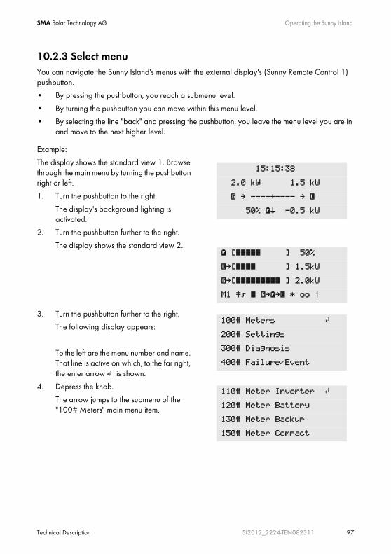
SMA Solar Technology AG Operating the Sunny Island
Technical Description SI2012_2224-TEN082311 97
10.2.3 Select menuYou can navigate the Sunny Island's menus with the external display's (Sunny Remote Control 1) pushbutton.
• By pressing the pushbutton, you reach a submenu level.
• By turning the pushbutton you can move within this menu level.
• By selecting the line "back" and pressing the pushbutton, you leave the menu level you are in and move to the next higher level.
Example:
The display shows the standard view 1. Browse through the main menu by turning the pushbutton right or left.
1. Turn the pushbutton to the right.
The display's background lighting is activated.
2. Turn the pushbutton further to the right.
The display shows the standard view 2.
3. Turn the pushbutton further to the right.
The following display appears:
To the left are the menu number and name. That line is active on which, to the far right, the enter arrow is shown.
4. Depress the knob.
The arrow jumps to the submenu of the "100# Meters" main menu item.
15:15:38
2.0 kW 1.5 kW
‡ ----+---- ‡
50% Š -0.5 kW
[¿¿¿¿¿ ] 50%
‡[¿¿¿¿ ] 1.5kW
‡[¿¿¿¿¿¿¿¿¿ ] 2.0kW
M1 ¿ ‡ ‡ * oo !
100# Meters
200# Settings
300# Diagnosis
400# Failure/Event
110# Meter Inverter
120# Meter Battery
130# Meter Backup
150# Meter Compact

Operating the Sunny Island SMA Solar Technology AG
98 SI2012_2224-TEN082311 Technical Description
5. Depress the pushbutton.
The arrow jumps one menu level further. Now you have three possibilities:
- Depress the pushbutton. The arrow jumps one level further. You can see parameters which are assigned to this menu.
- Select the line "back". To do this turn the pushbutton left or right until the "enter" arrow is on the appropriate line. Then press the pushbutton.
- Select the line "home". Press the pushbutton. Now you can see the standard view 1.
Sequence of the Menu Items
Menu items can be skipped over, i.e., you do not see all numbered parameters. This is related to the password level which is set. If you are using the device in user level, those parameters which should only be set by the installer do not appear. The menu numbers are fixed, that means they do not change if an entry (or several entries) are skipped.
111# Meter Total
112# Meter Device
[<-- back]
[<-- home]

SMA Solar Technology AG Operating the Sunny Island
Technical Description SI2012_2224-TEN082311 99
10.2.4 Selecting ParametersParameters are shown on the display as follows:
• To the left are the menu number and the parameter number. To the right, a bar shows the status of the value queried at present.
• To the left is the parameter name and to the right the "enter" arrow . The arrow indicates that this parameter can be adjusted.
• Magnitude and units.
10.2.5 Selecting EventsThe event list is found in the main menu, under 400# Failure/Event. Then go to the submenu 1 and activate 430# Event.
Events are shown on the display as follows:
• To the left are the menu number and name. To the right is the total number of events.
• Date and time of the event.
• Event and number (see chapter 18.5 "Events" (Page 185)).
• Description of the event
Syntax for this document
The syntax specified here for menus and parameters applies throughout the entire document.
A menu is marked by a hash mark, menu number and menu names (130# Meter Backup).
A parameter is marked with a menu number, dot (hash, on the display), parameter number and parameter name (131.01 TotExtPwrAt).
210#01 ¿
InvVtgNom
230.0 [V]
430# Event 001
2007-04-17 11:55:01
E101 ---
Silent

Operating the Sunny Island SMA Solar Technology AG
100 SI2012_2224-TEN082311 Technical Description
Skip back to the previous menu level:
• Turn the pushbutton completely to the left or right until "back" is shown on the display.
• Press the pushbutton
10.2.6 Selecting Warnings and FaultsThe warnings and faults list can be found in the main menu under 400# Failure/Event. Then go to the submenu 1.
• List of the current warnings and faults - 410# Fail Current.
• List of all warnings and faults (history) - 420# Fail History
Example:
Warnings and faults are shown on the display as follows:
• To the left are the menu number and name. To the right is the total number of instances for this particular warning or fault, to date.
• Date and time of the warning/fault.
• Warning or Fault and number (see chapter 18.7 "Warnings and Failure messages" (Page 188)). The "enter" arrow shows that the fault must be cleared and confirmed thereafter. Only thereafter can the Sunny Island be restarted.
• Description of the warning/fault.
Pending: The warning/fault is pending.
The fault has not yet been cleared.
Arrive: Time at which the warning/fault appeared.
Clear: The warning/fault has been cleared.
430# Event
[<-- back]
410# Pending 002
2007-04-17 11:55:01
W212 Warning
BatTempHigh

SMA Solar Technology AG Operating the Sunny Island
Technical Description SI2012_2224-TEN082311 101
10.3 Making adjustments
10.3.1 Adjusting parametersWith the pushbutton on the Sunny Remote Control 1 you can move through a menu and select the desired parameter. When the parameter appears on the display, you can read the current value.
The parameter can be adjusted if there is an "enter" arrow to the right after the parameter name.
1. Depress the knob.
2. The arrow skips behind the units and blinks.
3. Turn the pushbutton to the right or left. The value increases or decreases.
4. When the desired value appears on the display, save it. Press the pushbutton.
On the display appear "Ok? Y(es)/N(o)" and the "enter" arrow.
5. Select Y or N. The letter selected blinks.
With "Y" you can confirm the parameter change. With "N" you can discard the change and the old value remains in memory.
6. Press the pushbutton.
The parameter is set.
Adjusting parameters in standby
Note that some parameters can only be changed in standby mode. You can find the parameters for which this applies in the tables in chapters 17.2 "Adjustable System Parameters" (Page 166) and 17.5 "Functions During Operation" (Page 182).
222#02 ¿
AptTmBoost
120 [Min]
222#02 ¿
AptTmBoost
120 [Min]
222#02 ¿
AptTmBoost
120 [Min]
Ok? Y/N
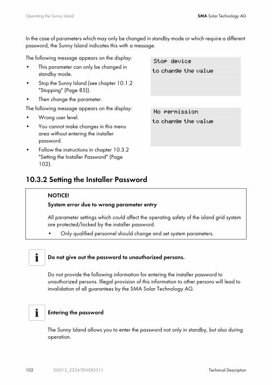
Operating the Sunny Island SMA Solar Technology AG
102 SI2012_2224-TEN082311 Technical Description
In the case of parameters which may only be changed in standby mode or which require a different password, the Sunny Island indicates this with a message.
The following message appears on the display:
• This parameter can only be changed in standby mode.
• Stop the Sunny Island (see chapter 10.1.2 "Stopping" (Page 85)).
• Then change the parameter.
The following message appears on the display:
• Wrong user level.
• You cannot make changes in this menu area without entering the installer password.
• Follow the instructions in chapter 10.3.2 "Setting the Installer Password" (Page 102).
10.3.2 Setting the Installer Password
NOTICE!
System error due to wrong parameter entry
All parameter settings which could affect the operating safety of the island grid system are protected/locked by the installer password.
• Only qualified personnel should change and set system parameters.
Do not give out the password to unauthorized persons.
Do not provide the following information for entering the installer password to unauthorized persons. Illegal provision of this information to other persons will lead to invalidation of all guarantees by the SMA Solar Technology AG.
Entering the password
The Sunny Island allows you to enter the password not only in standby, but also during operation.
Stop device
to change the value
No permission
to change the value
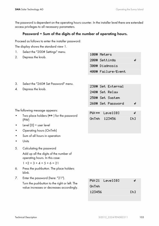
SMA Solar Technology AG Operating the Sunny Island
Technical Description SI2012_2224-TEN082311 103
The password is dependent on the operating hours counter. In the installer level there are extended access privileges to all necessary parameters.
Password = Sum of the digits of the number of operating hours.
Proceed as follows to enter the installer password:
The display shows the standard view 1.
1. Select the "200# Settings" menu.
2. Depress the knob.
3. Select the "260# Set Password" menu.
4. Depress the knob.
The following message appears:
• Two place holders (** ) for the password (PW)
• Level [0] = user level
• Operating hours (OnTmh)
• Sum of all hours in operation
• Units
5. Calculating the password
Add up all the digits of the number of operating hours. In this case:
1 +2 + 3 + 4 + 5 + 6 = 21
6. Press the pushbutton. The place holders blink.
7. Enter the password (here: "21").
Turn the pushbutton to the right or left. The value increases or decreases accordingly.
100# Meters
200# Settings
300# Diagnosis
400# Failure/Event
230# Set External
240# Set Relay
250# Set System
260# Set Password
PW:** Level[0]
OnTmh 123456 [h]
PW:21 Level[0]
OnTmh
123456 [h]

Operating the Sunny Island SMA Solar Technology AG
104 SI2012_2224-TEN082311 Technical Description
8. Confirm the password. Press the pushbutton.
The password is confirmed.
Operating level [1] = installer level has been set.
9. Leave menu.
Changing the operating level
If the password is invalid, the Sunny Island does not switch to the installer level. In this case, recalculate and re-enter the installer password as described in this section.
The installer level is reset to the user level if
• the Sunny Island is switched off and on again
• specific parameters are entered (e.g., the "510.01 InvRs" parameter) that cause a restart
• a wrong password is entered
• if no activity takes place within five minutes
PW:21 Level[1]
OnTmh
123456 [h]
260# Set Password 250# Set System
260# Set Password
[<-- back]
[<-- home]
SMA Solar Technology AG Operating the Sunny Island
Technical Description SI2012_2224-TEN082311 105
10.3.3 Accessing Parameters DirectlyUnder the menu "600# Direct Access" it is possible to directly access selected parameters via their name or number.
Via the Select Name submenu, you have direct access to the following functions:
• ManChargSel: manual starting of equalization charge (see section 12.4.3 "Equalization Charge" (Page 126))
Under the menu "Select Number" each parameter can be directly accessed by entering the parameter number.
10.3.4 Meter CompactThe "150# Meter Compact" menu should, above all, facilitate the commissioning for the installer. The display delivers information on the following items at a glance:
• Battery
• Inverter (AC values)
• grid/generator (external)
• Inverter status
Example
Using the menu 600# Direct Access, you can select the "222.01 BatChrgCurMax" parameter, for example, to set the maximum battery charging current.
The direct access must be entered as a five-digit number, for example, 22201. Here, the first three digits describe the menu number and the last two describe the parameter number.
After the parameter has been set successfully, exit the this menu level.
Select item
You can select among the various items within the Meter Compact by turning the pushbutton right or left.
Exit the menu by pressing the pushbutton.

Operating the Sunny Island SMA Solar Technology AG
106 SI2012_2224-TEN082311 Technical Description
Bat1 (Battery Values 1)
Inv (AC inverter values)
InvTot (total AC values of inverter)
260# Set Password Bat 75.2% 5.6%
8.6A 20.3degC
23.8V 27.8V
Full 05:00:00
BatTmp: Battery temperature
BatSocErr: Estimated error of of SOC
TotBatCur: Battery current
Name of the Meter Compact
BatSoc: present battery charge state
BatVtg: battery voltage
remaining charging time
BatChrgVtg: battery charging voltage
Bat ChrgOp: active charg-ing process
260# Set Password Inv 230V 50.0Hz
-0.6kW 0.1KVar
Name of the Meter Compact
InvVtg: present voltage at the inverter
InvFrq: present frequency at the inverter
InvPwrRt: present reactive power of the inverter
InvPwrAt: present active power of the inverter
260# Set Password Inv 230V 50.0Hz
-0.6kW 0.1KVar
Name of the Meter Compact
InvVtg: present voltage at the inverter
InvFrq: present frequency at the inverter
InvPwrRt: present reactive power of the inverter
InvPwrAt: present active power of the inverter

SMA Solar Technology AG Operating the Sunny Island
Technical Description SI2012_2224-TEN082311 107
ExtTot (Total AC Values of External Source)
OpStt (Inverter and Generator Status)
10.4 Saving Data onto a MMC/SD CardThe Sunny Remote Control 1 can store firmware, parameters and measured data on a Multimedia-Card (MMC/SD card) which must be FAT-16-formatted, with a max. size of 2 GB (possible memory sizes are 32/64/128/256/512 MB, 1GB and 2 GB). File names are saved in 8.3 format and files with other names are ignored.
Example of a format
A valid 8.3 format is, for example, "M1LOG.DAT".
8.3 is the "old" MS-DOS format with a file name that has max. 8 figures before and 3 figures after the dot.
Name of the Meter Compact 260# Set Password Ext 230V 51.1Hz
-1.5kW -0.2KVar
ExtVtg: Voltage of external source
ExtFrq: Frequency of external source
ExtPwrRt: Reactive power oexternal source ext. QuelleExtPwrAt: Active power of
external source
260# Set Password OpStt Run
Name of the Meter Compact
InvOpStt: Operating mode

Operating the Sunny Island SMA Solar Technology AG
108 SI2012_2224-TEN082311 Technical Description
After you have inserted the MMC/SD card into the card reader slot on your PC, you can search for the respective drive in the Explorer (in Microsoft Windows). You can see the following data on this drive (here: E:):
The files saved on the MMC/SD card have the following meaning:
Memory card types
The SMA Solar Technology AG recommends using MMC/SD cards manufactured by Transcend.
If you use a memory card by another manufacturer, check to see that it is a FAT-16-formatted card. If required, format the card. Be aware that, in doing this, data already stored on the card will be lost.
File name Meaning
evthism.log (evthisN.log for SlaveN) Event history of the device, saved by means of parameter "550.03 CardFunc", option StoEvtHis
SMA Solar Technology AG Operating the Sunny Island
Technical Description SI2012_2224-TEN082311 109
The Sunny Island's firmware expects device-specific data in the root directory of the MMC/SD card. This data consists of a new firmware, parameters and measurement data.
The Sunny Island uses the MMC/SD card in the Sunny Control 1 to store and load device parameters.
In addition, the Sunny Island supports the acquisition of measurement data on the MMC/SD card. It saves these data in a special file. Among other things, the file contains a header, time stamp, date and data type. There are two different types of log data:
• Measurement data (saved cyclically)
• Events and failures (only saved when they occur)
The Sunny Island supports measurement data storage of data from the fields:
• Battery
• Inverter
• System
• External source and
• Loads
failhism.log (failhisN.log for SlaveN) Failure history of the device, saved by means of parameter "550.03 CardFunc", option StoFailHis
si030607.evt Event/failure history for the day
(format: ddmmyy)
si030607.log Data recording for the day
(format: ddmmyy)
sipar1.lst Parameter list for the device, created by means of parameter "550.01 ParaSto", option Set1
sipar2.lst parameter list for the device, created by means of parameter "550.01 ParaSto", option Set2
update.bin Software for the device
Information
The "BOOTEX.LOG" file is not necessarily on the card. It is created depending on the operating system used (e.g. WindowsXP or Windows2000).
File name Meaning

Operating the Sunny Island SMA Solar Technology AG
110 SI2012_2224-TEN082311 Technical Description
The data saved on the MMC/SD card can be processed using common table calculation programs.
• The first 14 lines of the file are used for information (file header).
• This is followed by two column header lines.
• The data following this are separated by semicolons.
• Decimal places are separated by periods.
• The date format is dd.mm.yyyy
• The time format is hh:mm
Always save data
Always use the MMC/SD card for saving data and events. This way, in case of a failure, the SMA Solar Technology AG can help you quickly.
Log Data
For further information on processing log data see the instructions of the software used.

SMA Solar Technology AG Operating the Sunny Island
Technical Description SI2012_2224-TEN082311 111
10.4.1 Inserting the Card1. Insert the MMC/SD card with the clipped corner
toward the top (the sticker faces forward) into the external display's card slot.
2. After inserting the MMC/SD card, its removal is forbidden via a message on the display:
3. Initialization of the MMC-/SD card requires a few minutes.
On the display, three dots move along the bottom line.
4. If there is a fault, the following message appears on the display:
Do not remove
MMC/SD card...
MMC operation failed
Operating the Sunny Island SMA Solar Technology AG
112 SI2012_2224-TEN082311 Technical Description
10.4.2 Removing the CardTo ensure that all log data is saved upon deactivation, write all data not yet saved from the buffer to the MMC/SD card by using the parameter "550.03 CardFunc" with the option "ForceWrite".
10.4.3 Loading and Saving ParametersThe "550.01 ParaSto" parameter allows the storage of all the current parameter settings. Parameters already saved can be loaded using the "550.02 ParaLod" parameter.
When saving the parameters you have the following options:
• Set1 (save parameter set 1)
• Set2 (save parameter set 2)
When loading the parameters you have the following options:
• Set1 (load parameter set 1)
• Set2 (load parameter set 2)
• Factory (load the factory settings (reset))
Data Loss
If you remove the MMC/SD card without first activating the parameter "550.03 CardFunc", you will lose all data not yet saved since the last save process (15 minutes max.).
Saving Optimal Settings
If the system is working optimally, it is a good idea to save these settings. This is especially useful if you try something new and then later wish to reset the inverter back to the previous settings.
Overwrite protection
The write protection function of SD cards (plastic sliding clip on the left side) is not supported by the display. You should take note of this when writing data to your card.

SMA Solar Technology AG Operating the Sunny Island
Technical Description SI2012_2224-TEN082311 113
10.4.4 Writing Log Data Using the "550.04 DatLogEna" parameter, you can activate the writing of log data onto your MMC/SD card (activated by default).
10.4.5 Show StatusUsing the "312.07 CardStt" parameter, you can request the status of your MMC/SD card:
If the Sunny Remote Control 1 is writing data onto the MMC/SD card, removing the card is forbidden. The following message appears on the display:
Meaning Display
The MMC/SD card is deactivated.
Initialize the MMC/SD card.
The MMC/SD card is activated.
Do not remove
MMC/SD card...
312#07
CardStt
Off
312#07
CardStt
Mount
312#07
CardStt
Operational

Operating the Sunny Island SMA Solar Technology AG
114 SI2012_2224-TEN082311 Technical Description
10.4.6 Updating FirmwareThe firmware of the Sunny Island can be updated using the MMC/SD card. When the Sunny Island starts up or when the MMC/SD card is recognized, the Sunny Island searches for special update files on the MMC/SD card. If it detects such update files it conducts an update when it is on standby.
Meaning Display
The memory capacity of your MMC/SD is full.
The MMC/SD card has an invalid file format.
The MMC/SD card is incompatible.
Clearing Errors
For help on troubleshooting see section 18.8 "Troubleshooting" (Page 192).
New MMC/SD card
Always save the latest firmware version on the MMC/SD card first. Upon delivery this card is still empty (unwritten).
312#07
CardStt
Out Of Space
312#07
CardStt
Bad File Sys
312#07
CardStt
Incomp
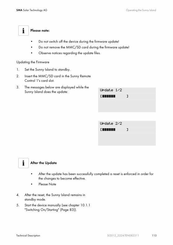
SMA Solar Technology AG Operating the Sunny Island
Technical Description SI2012_2224-TEN082311 115
Updating the Firmware
Please note:
• Do not switch off the device during the firmware update!
• Do not remove the MMC/SD card during the firmware update!
• Observe notices regarding the update files.
1. Set the Sunny Island to standby.
2. Insert the MMC/SD card in the Sunny Remote Control 1's card slot.
3. The messages below are displayed while the Sunny Island does the update:
After the Update
• After the update has been successfully completed a reset is enforced in order for the changes to become effective.
• Please Note
4. After the reset, the Sunny Island remains in standby mode.
5. Start the device manually (see chapter 10.1.1 "Switching On/Starting" (Page 83)).
Update 1/2
[¿¿¿¿¿¿ ]
Update 2/2
[¿¿¿¿¿¿ ]

Operating the Sunny Island SMA Solar Technology AG
116 SI2012_2224-TEN082311 Technical Description
Parameter settings
• Individual parameters and settings are retained during a firmware update.
• When updating, new parameters in the updated firmware are saved with the factory default values automatically.
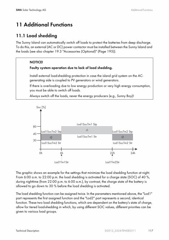
SMA Solar Technology AG Additional Functions
Technical Description SI2012_2224-TEN082311 117
11 Additional Functions
11.1 Load sheddingThe Sunny Island can automatically switch off loads to protect the batteries from deep discharge. To do this, an external (AC or DC) power contactor must be installed between the Sunny Island and the loads (see also chapter 19.3 "Accessories (Optional)" (Page 195)).
The graphic shows an example for the settings that minimize the load shedding function at night. From 6:00 a.m. to 22:00 p.m. the load shedding is activated for a charge state (SOC) of 40 %, during nighttime (from 22:00 p.m. to 6:00 a.m.), by contrast, the charge state of the battery is allowed to go down to 30 % before the load shedding is activated.
The load shedding function can be assigned twice. In the parameters mentioned above, the "Lod1" part represents the first assigned function and the "Lod2" part represents a second, identical function. These two load shedding functions, which are dependent on the battery's state of charge, allow for tiered load-shedding in which, by using different SOC values, different priorities can be given to various load groups.
NOTICE!
Faulty system operation due to lack of load shedding.
Install external load-shedding protection in case the island grid system on the AC-generating side is coupled to PV generators or wind generators.
If there is overloading due to low energy production or very high energy consumption, you must be able to switch off loads.
Always switch off the loads, never the energy producers (e.g., Sunny Boy)!

Additional Functions SMA Solar Technology AG
118 SI2012_2224-TEN082311 Technical Description
Define the time intervals t1 and t2:
• Starting time t1: with the parameter "242.05 Lod1Tm1Str", set the start time for t1 (and with it the end of t2).
• Starting time t2: with the parameter "242.06 Lod1Tm2Str", set the start time for t2 (and with it the ent of t1).
• If the time intervals t1 (Lod1Tm1Str) and t2 (Lod1Tm2Str) are consistent with one another, only t1 will be activated.
Set the battery state of charge at which the time interval t1 or t2 will start/stop:
• The battery state of charge during the t1 interval, the recognition of which will lead to the load-shedding function being started: Parameter "242.01 Lod1SocTm1Str"
• The battery state of charge during the t1 interval, the recognition of which will lead to the load-shedding function being stopped: Parameter "242.02 Lod1SocTm1Stp"
• The battery state of charge during the t2 interval, the recognition of which will lead to the load-shedding function being started: Parameter "242.03 Lod1SocTm2Str"
• The battery state of charge during the t2 interval, the recognition of which will lead to the load-shedding function being stopped: Parameter "242.04 Lod1SocTm2Stp"
11.2 Sleep ModeUsing the "250.10 SleepEna" parameter set to "Enable" allows the sleep mode to be activated in single-phase grids, which the master uses to switch off the slaves when the power value allows this.
11.3 Search ModeThe search mode is an energy-saving mode. When the power of the loads is less than 10 W for an definable period of time (Delta T), the Sunny Island switches to the search mode. In the search mode there is still voltage present at the AC1 terminal clamps.
With the parameter "250.26 SearchModTm", you can set the time interval Delta T (0 to 600 seconds).
Sleep Mode
• The "Sleep Mode" works exclusively in stand-alone grid operation!
• The values for the switching on and off of the Sunny Island are set at the factory and are fixed (and optimized for the efficiency rating).

SMA Solar Technology AG Additional Functions
Technical Description SI2012_2224-TEN082311 119
11.4 Time-controlled OperationThe Sunny Island can be operated in a time-controlled fashion using a timer function (like a clock timer), supplying power at a planned point in time.
To do this, this function must be activated by using the "510.02 InvTmOpEna" parameter. With the "510.03 InvTmOpStrDt" parameter you can specify the starting date, and with the "510.04 InvTmStrTm" you specify the starting time. With the parameter "510.05 InvTmOpRnDur" you set the running time and with the parameter "510.06 InvTmOpCyc" you determine whether this function will be carried out once, or every day or week, at or for the first time at the specified start time (date and time).
11.5 Overload and Short Circuit BehaviorThe Sunny Island can be operated under overload conditions temporarily. It can also supply short-circuit currents.
In the case of overload, the Sunny Island can deliver
• An output of 2900 W for 30 minutes at 25 °C
• An output of 3800 W for 5 minutes at 25 °C
In the event of a short circuit, the Sunny Island provides a maximum current of 25 A.
11.6 Device Failure and AutostartIf a critical fault occurs, the Sunny Island automatically shuts down and displays the reason on the display. If the autostart function is activated ("250.01 AutoStr" parameter) the Sunny Island can confirm the failure automatically and restart on its own. If the failure persists the Sunny Island cannot be started.
Information
If the autostart counter has counted down to 0, the Sunny Island waits for 10 minutes before attempting to restart automatically.
Information
Messages can be displayed during operation at any time, they have priority over the display of the "Home Screen".

Battery management SMA Solar Technology AG
120 SI2012_2224-TEN082311 Technical Description
12 Battery managementThe battery management of the Sunny Island supports the following three battery types ("221.01 BatTyp" parameter):
The battery capacity ("221.02 BatCpyNom" parameter) is to be entered as the nominal capacity for a ten hour discharge (C10). If this information is not available from the battery manufacturer's data sheet, it can be calculated from the data for different discharge times (120h, 100h, 20h, 5h, 1h) in the following manner:
The Sunny Island is designed and set by default (parameter "221.03 BatVtgNom") for a nominal battery voltage of
• 24 V (12 cells at 2 V each) in the case of lead batteries (FLA and VRLA)
• 22.8 V (19 cells at 1.2 V each) in the case of Nickel-Cadmium batteries
12.1 Battery temperatureThe Sunny Island continuously monitors the battery temperature using the battery temperature sensor provided. At 5 °C under the maximal temperature allowed (set using the " 221.04 BatTmpMax" parameter), a warning is displayed. If the maximal value for the battery temperature is exceeded, the Sunny Island switches off.
When lead acid batteries drop –10 °C below the set limit and NiCd batteries drop –20 °C below the set limit, a warning is displayed.
The battery temperature is taken into consideration when the charging voltage is calculated (see section 12.4 "Charge Control" (Page 122)).
FLA - Flooded Lead Acid: closed lead acid batteries with liquid electrolyte in all standard designs available on the market (grid plate, tubular plate, small, large, etc.)
VRLA - Valve Regulated Lead Acid: Closed lead acid batteries with immobilized electrolyte in gel or AGM (Absorbent Glass Mat Separator) in all standard designs available on the market (grid plate, tubular plate, small, large, AGM, Gel, etc.)
NiCd - Nickel-Cadmium: Pocket-type plate or fiber plate closed nickel cadmium batteries.
C10 C120/1.28 C10 C10
C10 C100/1.25 C10 C5/0.88
C10 C20/1.09 C10 C1/0.61
SMA Solar Technology AG Battery management
Technical Description SI2012_2224-TEN082311 121
12.2 Start OptionsIf the battery or individual cells are removed from the battery bank in a system, the battery management must be restarted and configured. This can be done using the "Quick Configuration Guide QCG" (see section 9.2 "Starting the Quick Configuration Guide (QCG)" (Page 76)).
12.3 Charge State/SOC and SOHThe Sunny Island has a very precise internal charge level calculation (display value "120.01 BatSoc"). The operation for calculating the charge level is based on balancing the ampere hours. This means that all currents flowing in and out of the battery are accumulated and referred to the nominal capacity. In order to take into consideration faults caused by self discharge and charging losses caused by gassing, these losses are already internally deducted. Unlike in case of other procedures, a fixed charging factor does not have to be set.
After full charge has been reached, the charge state value is reset to 90 %, 95 % or 100 %, depending on how fully the battery has been really loaded. If default settings are not changed, a state of charge of 90 % after boost charge, 95 % after full charge and 100 % after equalization charge is reached.
Since fully charged states are only rarely achieved, the operation used here can also use the battery voltage during constant discharge phases with low discharge currents to recalibrate the charge state. Due to these recalibrations at regular intervals, the procedure used here exhibits a high level of stability over the long term compared to the ampere hour balancing method.
Both the ampere hour balancing method and the recalibration procedure, which is performed via the voltage, automatically adjust to the connected battery over time (depends on the number of grid failures).
The estimated charge state error (display value "120.11 BatSocErr") will provide you with continuous information on the accuracy of the battery charge state currently calculated. With increasingly better adaptation to the actual battery state of charge, the average error is progressively reduced.
Only when the battery is new does its usable capacity correspond to the capacity specified by the battery manufacturer. As the battery ages and as a result of frequent insufficient charging, the battery’s useable capacity may decrease considerably on a permanent or only temporary basis.
NOTICE!
Possible damage to the battery as a result of faulty temperature measurement!
If the battery temperature sensor is defective or missing, the Sunny Island continues to run, assuming a battery temperature of 40 °C. This can result in insufficient charging of the battery in the long run.
• Please observe the corresponding warnings of the Sunny Island.
• Connect the battery temperature sensor.
• Replace the defective battery temperature sensor.

Battery management SMA Solar Technology AG
122 SI2012_2224-TEN082311 Technical Description
The battery's state of health (display value "320.01 Soh") is a measurement of the present useable capacity expressed as a percentage relative to the nominal capacity. 100 % means that the entire nominal capacity can be used. 50 % means that only half of the original nominal battery capacity can be used. The battery's state of health is also calculated by means of a self-adapting method which, however, can only produce good and exact values after a number of charging cycles.
The present capacity for the Sunny Island is automatically adjusted downwards for temperatures< 20 °C, since the useable capacity of batteries is significantly reduced at temperatures below the nominal temperature.
In the case of lead acid batteries the nominal capacity is adjusted by a fixed factor of –1 %/°C. In the case of NiCd batteries a factor of –0.75 %/°C is used.
12.4 Charge ControlThe Sunny Island uses a 3-phase charge control, using the IUoU procedure. When the device operates with the public grid, there is also an optional fourth phase called silent mode.
The I stands for the bulk phase (I phase). In this phase, charging is limited by the maximum defined battery current ("222.01 BatChrgCurMax" parameter), the nominal grid current ("232.03 GdCurNom" parameter) or the maximal AC charging current of the Sunny Island ("210.02 InvChrgCurMax" parameter).
In each case, whichever of these values is reached first functions as the limiting value. During this phase, the battery's voltage increases as its state of charge increases.
Once the battery voltage reaches the predefined value for the second phase Uo("222.07 — 222.09", ChrgVtgBoost or ChrgVtgFul or ChrgVtgEqu parameters), the constant voltage charging (absorption phase) begins.
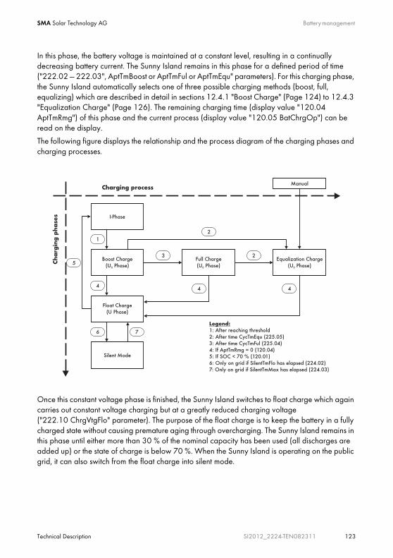
SMA Solar Technology AG Battery management
Technical Description SI2012_2224-TEN082311 123
In this phase, the battery voltage is maintained at a constant level, resulting in a continually decreasing battery current. The Sunny Island remains in this phase for a defined period of time ("222.02 — 222.03", AptTmBoost or AptTmFul or AptTmEqu" parameters). For this charging phase, the Sunny Island automatically selects one of three possible charging methods (boost, full, equalizing) which are described in detail in sections 12.4.1 "Boost Charge" (Page 124) to 12.4.3 "Equalization Charge" (Page 126). The remaining charging time (display value "120.04 AptTmRmg") of this phase and the current process (display value "120.05 BatChrgOp") can be read on the display.
The following figure displays the relationship and the process diagram of the charging phases and charging processes.
Once this constant voltage phase is finished, the Sunny Island switches to float charge which again carries out constant voltage charging but at a greatly reduced charging voltage ("222.10 ChrgVtgFlo" parameter). The purpose of the float charge is to keep the battery in a fully charged state without causing premature aging through overcharging. The Sunny Island remains in this phase until either more than 30 % of the nominal capacity has been used (all discharges are added up) or the state of charge is below 70 %. When the Sunny Island is operating on the public grid, it can also switch from the float charge into silent mode.

Battery management SMA Solar Technology AG
124 SI2012_2224-TEN082311 Technical Description
The charging capability of batteries is highly dependent on the battery temperature. For temperatures < 20°C, the charging voltage must be slightly increased, and for temperatures > 20°C it must be slightly decreased. This is necessary to prevent overcharging and insufficient charging reliably and at all battery temperatures. For this reason, the Sunny Island is equipped with automatic temperature compensation of the charging voltage. The charging voltage is adjusted by:
• 4 mV / °C and cell, in the case of VLA and FRLA battery types.
• 0 mV / °C and cell, in the case of NiCd batteries.
The temperature compensation value can be set using the "222.11 BatTmpCps" parameter.
12.4.1 Boost ChargeThe boost charge is the most common charging process of the Sunny Island. The boost charge ensures high generator capacity utilization through a high charging voltage over a short period of time. With liquid FLA lead acid batteries, this charge process should be used for gassing and thus homogenizing the electrolytes. The boost charge process can charge the battery up to approx.85 % to 90 %.
12.4.2 Full ChargeEvery 14 days or 8 nominal charge throughputs, the Sunny Island initiates a full charge automatically (parameter "222.05 CycTmFul").
The objective is to recharge the battery to a charge level of at least 95 % and to compensate the possible effects of an insufficient charge. A regular full charging every two to four weeks can double the battery service life in off-grid systems.
Charging voltage change
The charging voltage does not rapidly change, but is slowly adjusted to the new nominal value by approx. 0.5mV/cell*s as the constant voltage phase changes to the float charge. This also takes place if the nominal value is changed manually.
Nominal Charge Throughput
A nominal charge throughput is reached when the sum of the discharge currents corresponds to the rated capacity of the battery.
Example: the battery has a rated capacity of 100 Ah. A nominal charge throughput is reached when the battery has been discharged 10 times for 1 hour by 10A.

SMA Solar Technology AG Battery management
Technical Description SI2012_2224-TEN082311 125
Information
If the Sunny Island changes to full charge after a boost charge has been running for a specific time, this boost charge time is fully credited toward the full charge.
Information
If more than 1 % of the battery's nominal capacity is discharged during a full charge, 50 % of the time elapsed is credited towards the constant voltage phase.
External Charging Device
If an external charger or charge controller is connected to the battery and the criteria for a full charge are fulfilled due to external charging, the Sunny Island treats this as if it had performed the full charge itself.
Information
Any parallel procedures causing the generator to stop during the full charging process are not taken into account until the charging process is competed.
Battery management SMA Solar Technology AG
126 SI2012_2224-TEN082311 Technical Description
12.4.3 Equalization ChargeA battery bank consists of many individual battery cells connected in series which all behave slightly differently. Over time, this results in different charge levels in the individual cells. This can lead to premature failure, initially of individual cells, and finally to failure of the entire bank.
The Sunny Island can perform an equalization charge automatically every 180 days ("222.06 CycTmEqu" parameter) or every 30 nominal charge throughputs. During this process, it performs a controlled overcharging of the battery bank to ensure that even the weaker cells are fully recharged. Die Equalization charging extends the battery service life by up to 50 %. The automatic equalization charging function can also be deactivated ("222.12 AutoEquChrgEna" parameter, activated by default) or manually started ("520.01 ManChrgSel" parameter).
Notice
If the Sunny Island changes to equalization charge after boost charging or full charging has been running for a specific time, this time is credited toward the equalization charge completely.
Information
If more than 1 % of the battery's nominal capacity is discharged during an equalization charge, 50 % of the time elapsed credited toward the next constant voltage phase.
Information
If an external charger or charge controller is connected to the battery and the criteria for a full charge are fulfilled due to external charging, the Sunny Island treats this as if it had performed the full charge itself.

SMA Solar Technology AG Battery management
Technical Description SI2012_2224-TEN082311 127
12.4.4 Manual Equalization ChargeThe parameter "520.01 ManChrgSel" activates the manual equalization charge on the Sunny Island. If a generator is connected to the system, it will be automatically started, and stopped again after the equalization charge is completed.
12.4.5 Silent ModeIn addition to the float charge, the silent mode can be used ("224.01 SilentEna" parameter), only when operating on the public grid.
The main purpose of the silent mode is to save energy by switching from charge mode to standby mode in utility backup systems where the Sunny Island is predominantly in float charge.
The silent mode is activated after the time set for float charge ("224.02 SilentTmFlo" parameter) has expired. The Sunny Backup system remains in silent mode for a fixed time ("224.03 SilentTmMax" parameter) or until the battery voltage per cell is 0.14 V lower than the set voltage ("222.10 ChrgVtgFlo" parameter). This ensures that the battery is always fully charged, even in silent mode. If a grid outage is detected during silent mode, the Sunny Island makes a stand-alone grid available within a few milliseconds. The loads are supplied with power almost without interruption.
12.5 Battery Preservation ModeThe Sunny Island has a sophisticated battery preservation mode. The battery preservation mode prevents, as far as possible, the battery from being deeply discharged when the energy supply is low, preventing a total system failure as well as damage to the battery.
The battery preservation mode has three levels that are activated as a result of the state of charge (when the charge drops below the respective limit, parameters "223.05 BatPro1Soc", "223.06 BatPro2Soc" and "223.07 BatPro3Soc"):
Level 1: The first level is used to switch the Sunny Island into standby mode at times when the energy is not necessarily required (e.g., at night). You define the start time using the "223.01 BatPro1TmStr" parameter and the stop time using the "223.02 BatPro1TmStp" parameter.
Information
An equalization charge should be performed at least once a year. After a long period of time without charging, e. g., in the case of systems which are only operated seasonally, manual equalization charges are required at the end or at the beginning of the season.
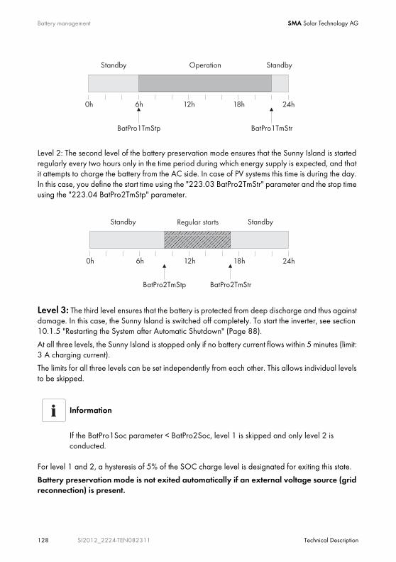
Battery management SMA Solar Technology AG
128 SI2012_2224-TEN082311 Technical Description
Level 2: The second level of the battery preservation mode ensures that the Sunny Island is started regularly every two hours only in the time period during which energy supply is expected, and that it attempts to charge the battery from the AC side. In case of PV systems this time is during the day. In this case, you define the start time using the "223.03 BatPro2TmStr" parameter and the stop time using the "223.04 BatPro2TmStp" parameter.
Level 3: The third level ensures that the battery is protected from deep discharge and thus against damage. In this case, the Sunny Island is switched off completely. To start the inverter, see section 10.1.5 "Restarting the System after Automatic Shutdown" (Page 88).
At all three levels, the Sunny Island is stopped only if no battery current flows within 5 minutes (limit: 3 A charging current).
The limits for all three levels can be set independently from each other. This allows individual levels to be skipped.
For level 1 and 2, a hysteresis of 5% of the SOC charge level is designated for exiting this state.
Battery preservation mode is not exited automatically if an external voltage source (grid reconnection) is present.
Information
If the BatPro1Soc parameter < BatPro2Soc, level 1 is skipped and only level 2 is conducted.

SMA Solar Technology AG Battery management
Technical Description SI2012_2224-TEN082311 129
The battery preservation mode can be quit by manually starting the Sunny Island. If a charging current is detected within 5 minutes (see above) the Sunny Island remains in operation; otherwise, it is disconnected again.
12.6 Battery DiagnosticsIn the menu "320 Battery Diagnosis", many values are displayed that provide information on the past operational behavior of the battery. These values are helpful in checking the efficiency of the set parameters and in viewing the typical operating conditions of the battery (see section 17.3 "Diagnosis" (Page 178)).

Connecting External Sources SMA Solar Technology AG
130 SI2012_2224-TEN082311 Technical Description
13 Connecting External SourcesThe Sunny Island supports the integration of external energy sources. A distinction is made between the integration of a generator and the integration of the public grid.
Both the generator ans the public grid are integrated via the Sunny Island's AC2 connection. A single-phase or a three-phase connection is possible. In the case of single-phase operation the transfer relays are operated in parallel, making it possible to use a correspondingly larger current, which in turn allows for a generator or grid connections with a higher capacity.
The Sunny Island has separate parameters for the grid and generators. It is therefore possible to use both operating modes without additional adjustments. The parameter settings and display values distinguish between settings or values which are generator-specific or grid-specific and settings or values (EXT) common to both grids and generators.
13.1 GeneratorThe Sunny Island can start or stop a generator depending on consumer power or battery state of charge. In this case, diverse limits and times are taken into consideration (see chapter 13.1.5 "Automatic Generator Operation" (Page 137)).
Connection in a Single-Phase Parallel System
When installing parallel1-phase systems, the connection cables for AC1 and AC2 of all Sunny Islands must have the same cable cross-sections and cable lengths.

SMA Solar Technology AG Connecting External Sources
Technical Description SI2012_2224-TEN082311 131
13.1.1 Connecting Generator Connections in ParallelIn the case of Sunny Islands connected in parallel and which operate on the same phase, the internal transfer relay is activated simultaneously. It is thus possible to multiply the generator current and therefore to connect a larger generator or a higher grid current.
The maximum value of the current depends on the number of transfer relays and therefore on the number of Sunny Islands connected in parallel. One can count on a maximal current of 25 A per Sunny Island.
13.1.2 Generator Start OptionsThe Sunny Island supports the following options for starting the generator which can be set in standby mode with the "233.07 GnStrMod" parameter:
• Manual
• Automatic start
• GenMan
Manual (Manual Generator Start)This setting is for generators that do not have an electrical remote starting option and are started using cable winches, cranks, or similar methods.
In this case, the Sunny Island has no way of starting the generator. It merely monitors the generator input (AC2). If, in doing this, the device detects that the generator voltage and frequency are within the set limits (see 13.1.6 "Limits and Power Adjustment" (Page 141)), the device is synchronized and switched on after the warm-up time.
Information
Use the same cable lengths when installing the Sunny Islands with the generator.

Connecting External Sources SMA Solar Technology AG
132 SI2012_2224-TEN082311 Technical Description
The following illustration shows the wiring for a generator that cannot be started remotely:
The generator must always be switched off manually too. The Sunny Island automatically switches to operation without generator.
Automatic startSo-called autostart generators can be integrated in this manner. These have an internal controller for the start procedure.
The Sunny Island requests the generator via the GnReq signal. If the generator voltage and frequency are within the set limits (see 13.1.6 "Limits and Power Adjustment" (Page 141)), the device is synchronized and switched on after the warm-up time.
The Sunny Island keeps the request signal active until a disconnection is made and the set power-down time has expired.
GnReq Signal
The GnReq signal (see 14 "Relay" (Page 152)) is set to signal the generatordeployment request and can therefore be used as an notification contact. If the generator is no longer required the signal is deactivated.
In case this request occurs when the generator is running the signal is suppressed until the generator has externally been stopped and the stop time has expired (30 seconds).
Disconnecting the generator
A disconnector should be positioned between the Sunny Island and the generator. If the generator is to be stopped, it is first manually disconnected using the disconnector and then it is stopped. This prevents the actuation of the generator when switching off.
Generator
PE N L PE N LPE
AC1 AC2
Sunny Island
PENL
N
C
Island GridPENL
Relay1
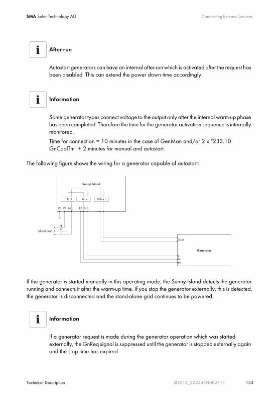
SMA Solar Technology AG Connecting External Sources
Technical Description SI2012_2224-TEN082311 133
The following figure shows the wiring for a generator capable of autostart:
If the generator is started manually in this operating mode, the Sunny Island detects the generator running and connects it after the warm-up time. If you stop the generator externally, this is detected, the generator is disconnected and the stand-alone grid continues to be powered.
After-run
Autostart generators can have an internal after-run which is activated after the request has been disabled. This can extend the power down time accordingly.
Information
Some generator types connect voltage to the output only after the internal warm-up phase has been completed. Therefore the time for the generator activation sequence is internally monitored.
Time for connection = 10 minutes in the case of GenMan and/or 2 x "233.10 GnCoolTm" + 2 minutes for manual and autostart.
Information
If a generator request is made during the generator operation which was started externally, the GnReq signal is suppressed until the generator is stopped externally again and the stop time has expired.
Generator
PE N L PE N LPE
AC1 AC2
Sunny Island
Relay1
PENL
Island Grid
PENL
Start
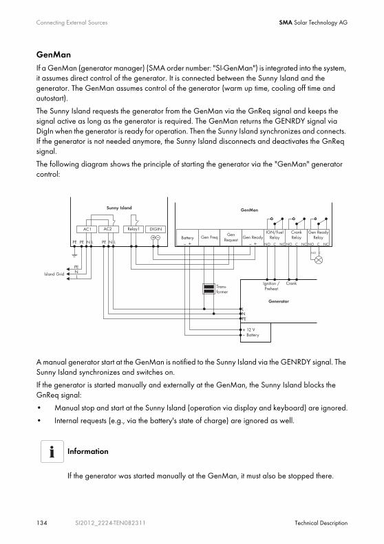
Connecting External Sources SMA Solar Technology AG
134 SI2012_2224-TEN082311 Technical Description
GenManIf a GenMan (generator manager) (SMA order number: "SI-GenMan") is integrated into the system, it assumes direct control of the generator. It is connected between the Sunny Island and the generator. The GenMan assumes control of the generator (warm up time, cooling off time and autostart).
The Sunny Island requests the generator from the GenMan via the GnReq signal and keeps the signal active as long as the generator is required. The GenMan returns the GENRDY signal via DigIn when the generator is ready for operation. Then the Sunny Island synchronizes and connects. If the generator is not needed anymore, the Sunny Island disconnects and deactivates the GnReq signal.
The following diagram shows the principle of starting the generator via the "GenMan" generator control:
A manual generator start at the GenMan is notified to the Sunny Island via the GENRDY signal. The Sunny Island synchronizes and switches on.
If the generator is started manually and externally at the GenMan, the Sunny Island blocks the GnReq signal:
• Manual stop and start at the Sunny Island (operation via display and keyboard) are ignored.
• Internal requests (e.g., via the battery's state of charge) are ignored as well.
Information
If the generator was started manually at the GenMan, it must also be stopped there.
SMA Solar Technology AG Connecting External Sources
Technical Description SI2012_2224-TEN082311 135
The generator is disconnected by the Sunny Island after the GENRDY signal has been withdrawn by the GenMan.
13.1.3 Generator OperationThe Sunny Island allows automatic operation (charge state- or load-dependent) (see 13.1.5 "Automatic Generator Operation" (Page 137)). In addition, manual operation is also possible.
13.1.4 Manual Generator OperationThe manual operating modes for the generator management are triggered using the "540.01 GnManStr" parameter. The following operating modes are distinguished:
An equalization charge can be manually started using the "520.01 ManChrgSel" parameter. The battery management (see section 12 "Battery management" (Page 120)) is set into the equalization charge state and requests the generator. This request persists until equalization charge has been completed.
The following sequence charts provide an overview of the start/stop behavior of the Sunny Island in the case of automatic generator operation:
Caution!
A manual start directly at the generator is not possible (see GenMan manual). Unforseeable operational states could result (see the GenMan manual).
Auto: In this operating mode, the generator is automatically started due to the settings. This includes the start via the state of charge or the consumer power or by the request for a manual equalization charge.
("520.01 ManChrgSel" = Start).
Stop: The generator is stopped manually. Cancels the present generator request – immediately disconnects from the generator and transitions into the lockout state. Once the lockout time has ended, the generator switches into automatic operation. The generator can now be started manually.
Start: Manual generator start – the generator runs "continuously" until stopped. The generator can only be stopped manually.
Run1h: Operation for one hour. Once the lockout time has expired, the transition back into automatic mode follows.

Connecting External Sources SMA Solar Technology AG
136 SI2012_2224-TEN082311 Technical Description
Generator Interface 233.07 GnSrtMod Manual; Start at the Generator
Generator Interface 233.07 GnSrtMod Autostart; Start at the Generator
* Transfer Relay
1 Manual generator start
2 "Generator is running" detected, beginning of warm-up phase
3 Internal generator request is ignored
4 Warm-up phase is completed, generator is connected
5 Generator current limiation
6 Current is reduced, battery absorption phase
7 Manual generator stop, disconnection of the generator
8 Minimum generator stop time has expired
1 Manual generator start
2 "Generator is running" detected, beginning of warm-up phase
3 Warm-up phase is completed
4 Generator is connected
5 Generator current limiation
6 Current is reduced, battery absorption phase
7 Manual generator stop, disconnection of the generator
8 Generator is disconnected, beginning of stop time
9 End of stop time
Gn
GnReq
TrfRel*
ExtCur
Warm-up time Stop time
87
65
4
12
3
Gn
GnReq
TrfRel*
ExtCur
9
8
7
65
4
1
2 3

SMA Solar Technology AG Connecting External Sources
Technical Description SI2012_2224-TEN082311 137
Generator Interface 233.07 GnSrtMod GenMan; Start at the Generator
* Transfer Relay
13.1.5 Automatic Generator OperationIn automatic operating mode ("234.01 GnAutoEna" parameter), the Sunny Island automatically defines the settings (as a function of battery charge state or loads) to determine when the generator starts and how long it runs. The automatic operating mode is enabled via GnAutoEna = On (Default). If GnAutoEna = Off, the automatic operating mode is deactivated.
In addition, the user can also manually start and stop the generator, if required.
State-of-charge dependent start
The time periods t1 and t2 are defined using the "234.07 GnTm1Str" and "234.08 GnTm2Str" parameters respectively. The start time for t1 (and the end of t2) is defined with "GnTm1Str" and the start time for t2 (end of t1) is defined with "GnTm2Str".
1 Generator start at GenMan
2 Beginning of GenMan generator warm-up phase
3 Generator warm-up time
4 GenMan sends ready for connection signal
5 Generator is connected via Sunny Island
6 Current limitation
7 Current is reduced, battery absorption phase
8 GenMan signals generator stop
9 Generator disconnection via Sunny Island
10 Generator post-run period completed, generator stop
11 Stop time has expired
NOTICE!
• Manual inputs on the Sunny Island have a higher priority than automatic operation.
• If the Sunny Island is manually stopped while the automatic operating mode is activated it switches to stop/lock operating mode.
• If Generator Automatic Start is activated and the conditions for automatic operation are met, the Sunny Island changes back into the Start operating mode after lock time (or manual acknowledgment with the "540.02 GnAck" parameter).
Gn
GnReq
GnRun (DigIn)
TrfRel*
ExtCur
1110
8
9
76
5
4
32
1

Connecting External Sources SMA Solar Technology AG
138 SI2012_2224-TEN082311 Technical Description
The time intervals t1 and t2 are assigned charge states for start-up and stop with the "234.03 GnSocTm1Str", "234.04 GnSocTm1Stp", "234.05 GnSocTm2Str" and "234.06 GnSocTm2Stp" parameters. GnSocTm1Strt designates the battery charge state at which the generator is started during the t1 time and GnSocTm1Stp designates the charge state at which the generator is switched off during t1. The GnSocTm2Str and GnSocTm2Stp parameters are similarly defined in relation to the time t2.
Information
If GnTm1Str = GnTm2Str, only t1 is active!
Example
The figure displays an example of the settings if operation of the generator at night is to be avoided as much as possible. Between 6 a.m. and 6 p.m., the generator is started at a charge state (SOC) of 40 % and by contrast, the battery is discharged to 30 % at night (between 6 p.m. and 6 a.m.) before the diesel generator starts.

SMA Solar Technology AG Connecting External Sources
Technical Description SI2012_2224-TEN082311 139
Load-dependent StartThe generator can be requested for support in case of increased power consumption. This function can be switched on or off (default) using the "234.09 GnPwrEna" parameter. The function is only effective if the "234.01 GnAutoEna" parameter is simultaneously set to On.
The load limit for the request and the generator stop is configured using the "234.10 GnPwrStr" and "234.11 GnPwrStp" parameters. The averaging time used to calculate an average value for the consumer power can be set using "234.12 GnPwrAvgTm". This prevents temporary power consumption peaks of a few seconds from causing a load-dependent generator start.
If the generator has been started load-dependently, it will run for the generator minimum runtime. If, once this time has expired, the average power is below the cutoff limit, the generator is stopped again.
Information
If the float charging process (see section 12.4 "Charge Control" (Page 122)) is activated before the cutoff limit (GnSocTm1Stp or GnSocTm2Stp) is reached, the generator request is disabled again. If a full or equalization charge is active, the generator is only stopped after this charge is completed and not when "234.04 GnSocTm1Stp" or "234.06 GnSocTm2Stp" is reached.
Multiple-phase system
Only the total consumer power of all phases is monitored. Individual phases in a multi-phase system are not monitored.
The consumer power is calculated using the inverter power ("111.01 TotInvPwrAt" parameter) and generator power ("131.01 TotExtPwrAt" parameter).
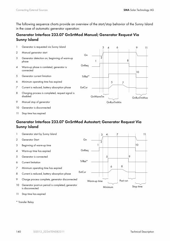
Connecting External Sources SMA Solar Technology AG
140 SI2012_2224-TEN082311 Technical Description
The following sequence charts provide an overview of the start/stop behavior of the Sunny Island in the case of automatic generator operation:
Generator Interface 233.07 GnSrtMod Manual; Generator Request Via Sunny Island
Generator Interface 233.07 GnSrtMod Autostart; Generator Request Via Sunny Island
* Transfer Relay
1 Generator is requested via Sunny Island
2 Manual generator start
3 Generator detection on, beginning of warm-up phase
4 Warm-up phase is comleted, generator is connected
5 Generator current limiation
6 Minimum operating time has expired
7 Current is reduced, battery absorption phase
8 Charging process is completed, request signal is disabled
9 Manuel stop of generator
10 Generator is disconnected
11 Stop time has expired
1 Generator start by Sunny Island
2 Generator Start
3 Beginning of warm-up time
4 Warm-up time has expired
5 Generator is connected
6 Current limitation
7 Minimum operating time has expired
8 Current is reduced, battery absorption phase
9 Charge process complete, generator disconnected
10 Generator post-run period is completed, generator is disconnected
11 Stop time has expired
Gn
GnReq
TrfRel*
ExtCur
GnWarmTm
GnRunTmMin
GnRunTmMax
12
3 4
5
6
7
8
9
10
11
Stop time
Post run
Minimum
Warm-up time
Gn
GnReq
TrfRel*
ExtCur
12
3 4
5
6
7
8
9
10
11
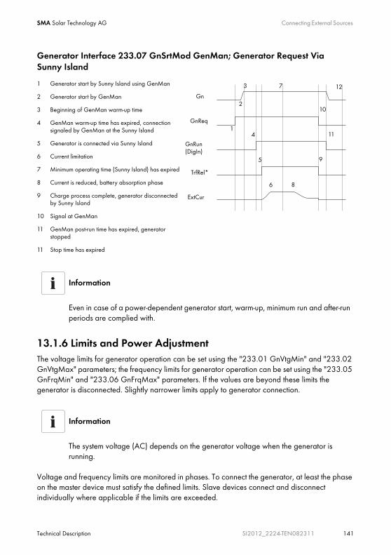
SMA Solar Technology AG Connecting External Sources
Technical Description SI2012_2224-TEN082311 141
Generator Interface 233.07 GnSrtMod GenMan; Generator Request Via Sunny Island
13.1.6 Limits and Power AdjustmentThe voltage limits for generator operation can be set using the "233.01 GnVtgMin" and "233.02 GnVtgMax" parameters; the frequency limits for generator operation can be set using the "233.05 GnFrqMin" and "233.06 GnFrqMax" parameters. If the values are beyond these limits the generator is disconnected. Slightly narrower limits apply to generator connection.
Voltage and frequency limits are monitored in phases. To connect the generator, at least the phase on the master device must satisfy the defined limits. Slave devices connect and disconnect individually where applicable if the limits are exceeded.
1 Generator start by Sunny Island using GenMan
2 Generator start by GenMan
3 Beginning of GenMan warm-up time
4 GenMan warm-up time has expired, connection signaled by GenMan at the Sunny Island
5 Generator is connected via Sunny Island
6 Current limitation
7 Minimum operating time (Sunny Island) has expired
8 Current is reduced, battery absorption phase
9 Charge process complete, generator disconnected by Sunny Island
10 Signal at GenMan
11 GenMan post-run time has expired, generator stopped
11 Stop time has expired
Information
Even in case of a power-dependent generator start, warm-up, minimum run and after-run periods are complied with.
Information
The system voltage (AC) depends on the generator voltage when the generator is running.
Gn
GnReq
TrfRel*
ExtCur
GnRun (DigIn)
1
2
3
4
5
6
7
8
9
10
11
12
Connecting External Sources SMA Solar Technology AG
142 SI2012_2224-TEN082311 Technical Description
The Sunny Island burdens the generator at each phase with the current defined in the parameter "233.03 GnCurNom". The power not directly used by the loads flows into the battery for charging. At the same time, the limits for the AC charging current limit ("210.02 InvChrgCurMax" parameter) on the Sunny Island and the DC charging current limit ("222.01 BatChrgCurMax" parameter) are active.
Low values for these limits may be the reason why the defined generator current cannot be adjusted. If the battery voltage reaches the charging voltage nominal value, it is also reduced (absorption phase, see section 12.4 "Charge Control" (Page 122)).
If the "233.15 GnCtlMod" parameter is set to CurFrq, the generator is also limited at frequencies lower than the nominal frequency ("233.04 GnFrqNom" parameter). This function can be used if the full generator output is not always available and you want to prevent the generator from being overloaded. The default setting is only intended to control the nominal generator current.
If the current set using the "233.03 GnCurNom" parameter is not sufficient for powering the loads, the battery provides support ("real generator support").
The Sunny Island provides all the required reactive power.
Information
If the master device disconnects the generator, all slave devices are disconnected as well.
Information
If a slave device is disconnected from a generator (and the master continues to be connected to the generator), the slave device can reconnect once the voltage and frequency are within the valid range again.
There is, however, a monitoring period in this case. Only after voltage and frequency are determined to be valid according to the "233.12 GnWarmTm" parameter does reconnection take place.
Information
A sensible value for the "233.03 GnCurNom" parameter is approximately 80 % of the maximum generator current for each phase.
SMA Solar Technology AG Connecting External Sources
Technical Description SI2012_2224-TEN082311 143
13.1.7 Run TimesIf the generator is started (or the Sunny Island detects an external generator start), the warm-up phase starts. If, during this time, the voltage or frequency detected is not within the permissible range, the warm-up phase begins again.
If the generator cannot be connected at the GenMan within twice the time set at "233.12 GnWarmTm" + 2 or 10 minutes, the connection process is cancelled and a new attempt is made. After three attempts, the system changes to error state (Fail).
If the generator has been connected, the minimum run time begins ("233.08 GnOpTmMin" parameter). The generator remains connected during this time, even if in the meantime the generator request is no longer present.
If the minimum run time has ended and a generator request is no longer present, the generator disconnects and enters the power down phase (Cool). If this power down phase is completed after the time specified in "233.10 GnCoolTm", the generator is stopped.
If a generator fault (e.g. generator failure) is detected, the generator is also disconnected and then stopped immediately. In doing so, the power-down time is skipped.
Once the stop time (233.09 GnStpTmMin" parameter) has elapsed, the generator is ready for the next request.
If a generator fault is detected several times and the number of autostarts ("234.02 GnAutoStr" parameter) has been exceeded, the system transitions into the locked error state.
This state lasts for the time period set at "233.11 GnErrStpTm". Once this time has elapsed, the generator is ready for another attempt.
Information
The power-down time ("233.10 GnCoolTm" parameter) defined on the Sunny Island should be set equal to or preferably greater than the power-down time of the GenMan.
Information
An internal generator request is disabled during the power down time and stop time or in error state.

Connecting External Sources SMA Solar Technology AG
144 SI2012_2224-TEN082311 Technical Description
The "133.03 GnRmgTm" process value is used to display the remaining time of the generator meter.
Depending on the current request or the phase in which the generator state machine is, the following times are displayed:
• Remaining time of Run1h
• Remaining run time during the warm-up phase (Warm)
• Remaining minimum run time in operation (Run)
• Remaining run time during the power-down time (Cool)
• Remaining stop time after the power down-time has elapsed (Lock)
• Remaining time in the error state (Fail)
• Remaining time in the locked error state (FailLock)
13.1.8 Operation Together With Sunny Boys
If the battery is fully charged, the frequency limits the power output of the AC feed-in generators (Sunny Boys). If the generator is now manually started, for example, the frequency would be lowered, if required, as the Sunny Island synchronizes with the generator. The AC feed-in generators (Sunny Boys) would then feed additional energy into the system and possibly overload the batteries.
Information
The recording of autostarts is only reset after the generator has been successfully connected and the minimum run time has expired or when the locked error state (FailLock) is disabled.
Information
The error state and the locked error state can be cancelled by confirming the generator fault ("540.02 GnAck" parameter).
NOTICE!
Damage to devices due to improper installation dimensioning.
When dimensioning your installation, please observe:
PAC max., Sunny Boy = 2 x PAC nom., Sunny Island
• The maximal AC output of the Sunny Boy inverter connected should not exceed 4.4 kW.

SMA Solar Technology AG Connecting External Sources
Technical Description SI2012_2224-TEN082311 145
In order to prevent this during such conditions, the stand-alone grid frequency is temporarily increased ("231.04 AcSrcFrqDel" parameter), in line with the synchronization, until the AC feed-in generators (Sunny Boys) are disconnected from the stand-alone grid as a result of the grid limits being exceeded.
13.1.9 Stopping the GeneratorIf the generator was started via the Sunny Island (automatically or manually), it can be manually stopped at any time using the "540.01 GnManStr" parameter. This disconnects the generator (the minimum run time is not taken into account here), and the power-down time (Cool) is skipped. Afterwards, the system enters the the stop time (Lock).
DANGER!
Death hazard due to high voltages
The power-down time depends on the generator type.
During the power-down time, there is still grid voltage at the consumers.
• Wait until the generator stops.
Information
Generators with the "manual" start option can generally only be started and stopped at the generator.
Information
If the generator start is to be disabled after a manual stop, this must be performed by setting the "234.01 GnAutoEna" parameter to "Off".

Connecting External Sources SMA Solar Technology AG
146 SI2012_2224-TEN082311 Technical Description
13.1.10 FailuresReverse PowerIf the reverse power ("233.13 GnRvPwr" parameter) set for the "233.14 GnRvTm" time is exceeded, the generator is disconnected and stopped. The power down time (Cool, parameter "233.10 GnCoolTm") is skipped and the system transitions into the minimum stop time (Lock). After reverse power, the connection is blocked for at least for the period "231.02 ExtLkTm" or "233.09 GnStpTmMin".
Generator FailureIf a generator failure is detected (failure on the master phase), the generator is disconnected immediately and a stop signal is activated at the generator. The system enters the the stop time (Lock).
Generator Phase FailureThe breakdown of a phase (e.g., blown fuse) at a slave device is treated as a phase breakdown. The slave device then disconnects this phase. If the phase is detected as being available again, it is reconnected after the warm up time "233.12 GnWarmTm" has elapsed.
The phase failure on the master device is treated as a generator failure (see above).
Slave Device FailureIf a slave device fails, the system continues to operate using both the remaining devices of the cluster as well as those on the generator.
13.2 GridThe Sunny Island supports the operation of grid backup systems on the grid. Here, a distinction is made between two main states: either a main power grid and stand-alone grid are connected or a main power grid and stand-alone grid are disconnected. The operating mode of the Sunny Island is derived from this. If the stand-alone grid is disconnected, the inverter alone is responsible for powering this stand-alone grid. If the main power grid is connected to the stand-alone grid, the stand-alone grid is powered from the main power grid. The voltage and frequency in the stand-alone grid and in the main power grid are identical.
Information
Under specific conditions, the system can also temporarily feed energy from the stand-alone grid into the main power grid in the GridCharge operating mode ("232.08 GdMod" parameter).

SMA Solar Technology AG Connecting External Sources
Technical Description SI2012_2224-TEN082311 147
13.2.1 ConditionsIn order to operate on the grid, very strict limits (for voltage and frequency) must generally be maintained. This strict limits are not sensible for generator operation. The limits are therefore set separately for grid operation and the generator limits are not used.
13.2.2 Stand-Alone Grid OperationThe main power grid and stand-alone grid are disconnected and the Sunny Island powers the stand-alone grid. The system waiting for the grid to reconnect is an indication of this state.
As long as the battery has a sufficient charge level, the loads are powered. In stand-alone operation, the AC feed-in generators (e.g. Sunny Boys) perform a charge operation, if required.
13.2.3 Grid ReconnectionIn stand-alone operation, the Sunny Island constantly checks whether the grid has been reconnected (see above). If the voltage and frequency of the main power grid are within the permissible range of the "232.01 GdVtgMin" and "232.02 GdVtgMax" parameters for the time set it "232.07 GdVldTm"; and if the frequency is within the permissible range of the "232.05 GdFrqMin" and "232.06 GdFrqMax" parameters (see also chapter 13.2.1 "Conditions" (Page 147)), the stand-alone grid is synchronized with the main power grid and then connected.
Information
The default settings for limits during grid operation comply with the following standards:
• For 230V_50Hz: DIN VDE 0126-1-1 (not entirely)
NOTICE!
The Sunny Island does not meet the VDE 0126-1-1 directive required in Germany and, for legal reasons, it must therefore be MSD-certified (e.g. by UfE GmbH) when operated while connected to the public grid.
Connecting External Sources SMA Solar Technology AG
148 SI2012_2224-TEN082311 Technical Description
13.2.4 Grid OperationIn grid operation, the stand-alone grid and main power grid are connected. The Sunny Island is connected along with the stand-alone grid to the main power grid. Therefore, the voltage and frequency in both grids are identical.
In grid operation, the grid monitors whether the permissible limits for voltage and frequency (see Grid Reconnection) are maintained or whether the grid fails to assume powering the stand-alone grid. To do this, the main power grid is disconnected (grid backup operation).
The battery is generally charged or its charge is maintained on the grid.
Charge ModeCharge mode on the grid is indicated by energy flowing to the battery. The battery is charged until the respective charge process (Boost, Full, Equalize) has been completed and the system transitions into float charge (Float) (see chapter 12.4 "Charge Control" (Page 122)).
Silent ModeIn order to save energy, the silent mode can be activated using the 224.01 SilentEna" parameter set to "enable" (default disable). In this case, the Sunny Island is set to standby mode if the charge has been completed and the battery has been in float charge for some time (see section 12.4.5 "Silent Mode" (Page 127)).
The silent mode is exited regularly to recharge the battery.
Grid feedingWhether energy is fed from the stand-alone grid into the main power grid is controlled using the "232.08 GdMod" parameter. If GridCharge (Default) is set, no energy is fed into the grid. If GridFeed is set, energy is fed into the grid.
AC feed-in generators on the stand-alone grid side (Sunny Boys) can feed their energy into the grid through the internal transfer relay of the Sunny Island; for limitations, see section 13.2.7 "Limits and Power Adjustment" (Page 149).
Information
All grid failures that occur during grid operation affect the stand-alone grid.
Information
In order to allow electricity to be fed from the battery into the grid, the battery voltage in a charged battery (on the grid) must be increased by external DC chargers above the nominal charging voltage.

SMA Solar Technology AG Connecting External Sources
Technical Description SI2012_2224-TEN082311 149
13.2.5 Grid FailureA grid fault is characterized by the voltage or frequency being outside of the permissible limits (see section 13.2.3 "Grid Reconnection" (Page 147)) or the main power grid being disconnected. In this case, the time limits are relevant: Smaller deviations are permitted for longer than large deviations (see section 13.2.1 "Conditions" (Page 147)).
In case of a grid fault/failure, the public grid is disconnected and the inverter starts, if it is not already running (silent mode).
13.2.6 FailuresReverse PowerIf the defined reverse power ("232.09 GdRvPwr" parameter) is exceeded for the time "232.10 GdRvTm", the grid is disconnected. After reverse power, connection is blocked for at least for the amount of time set at "232.07 GdVldTm".
Grid FailureIf a grid failure is detected (failure at the master phase), the grid is disconnected immediately.
Grid Phase FailureThe breakdown of a phase (e.g., blown fuse) at a slave device is treated as a phase breakdown. The slave device then disconnects this phase. If the phase is detected as being available again, it is reconnected.
The phase failure on the master device is treated as a grid failure (see above).
13.2.7 Limits and Power AdjustmentThe Sunny Island burdens the generator at each phase with the current defined in the parameter "233.03 GnCurNom". The power not directly used by the loads flows into the battery for charging. At the same time, the limits for the AC charging current limit ("210.02 InvChrgCurMax" parameter) on the Sunny Island and the DC charging current limit ("222.01 BatChrgCurMax" parameter) are active. If the battery voltage reaches the charging voltage nominal value, it is also reduced (see section 12.4 "Charge Control" (Page 122)).
If the current set using the "232.03 GdCurNom" parameter is not sufficient for powering the loads, the battery provides support.
Information
If the Sunny Island is in silent mode when there is a public grid failure, there is a short outage in the stand-alone grid (see chapter 12.4.5 "Silent Mode" (Page 127)).

Connecting External Sources SMA Solar Technology AG
150 SI2012_2224-TEN082311 Technical Description
13.2.8 Operation Together With Sunny BoysSince electricity is fed into the grid through the relay of the Sunny Island, it must be prevented from overloading. For this reason, reverse power monitoring is used which, if required, disconnects the main power grid if the reverse power limit is exceeded or an excessive load is applied to the relay.
If the battery is fully charged, the frequency limits the power output of the AC feed-in generators (Sunny Boys) in the stand-alone grid. If the grid is now reconnected, the frequency would be lowered, if required, as the Sunny Island is synchronized with the grid. The AC feed-in generators (Sunny Boys) would then feed additional energy into the system and possibly overload the batteries. In order to prevent this, in this case the stand-alone grid frequency is temporarily increased ("231.04 AcSrcFrqDel" parameter), in line with the synchronization, until the AC feed-in generators (Sunny Boys) are disconnected from the stand-alone grid as a result of the grid limits being exceeded.
NOTICE!
If the current flowing through the relay exceeds the maximum permissible current, the grid is disconnected (relay protection). The quantity of PV output installed in the stand-alone grid must not exceed the maximum quantity allowed by the AC input (see section 20 "Technical Data" (Page 197)).

SMA Solar Technology AG Connecting External Sources
Technical Description SI2012_2224-TEN082311 151
13.3 Generator and GridIn addition to the public grid, a generator can also be integrated into an island grid system as a secondary protective measure. This is particularly useful in case of long-term grid failures, if after some time the battery size no longer suffices either, to bridge the failure.
The standard solution in such cases is to use a transfer switch that can be purchased as a manual or an automatic switch. By using such a switch, theAC2 connection, to which the public grid is normally connected, switches to a connection with a diesel generator, as shown in the figure below:
To use such a switch, proceed with the installation as follows:
1. Connect the negative pole of the DigIn connection on the Sunny Island to the negative pole of the BatVtgOut connection, also located on the Sunny Island.
2. Connect the positive pole of the DigIn connection to a NO connection of an auxiliary contact of the transfer switch.
3. Connect the positive pole of the BatVtgOut connection to the second contact of the same auxiliary contact on the transfer switch.
An auxiliary contact is used because the Sunny Island must “know” whether it is connected to the public grid or whether it must manage a diesel generator.
To enable such operation, the “GenGrid” (GridBackup + Generator) selection is absolutely imperative (see section 9.2 "Starting the Quick Configuration Guide (QCG)" (Page 76)).
Information
All the settings that you have performed for the generator and grid in the submenus also apply to the “GridBackup + Generator” selection.

Relay SMA Solar Technology AG
152 SI2012_2224-TEN082311 Technical Description
14 RelayThe Sunny Island offers you several options for the control of internal and external processes. For this purpose, there are two relays integrated into the device to which you can assign functions using the "241.01 Rly1Op" and "241.02 Rly2Op" parameters. Information on connecting the relays is provided in section 7.6.3 "Multi-function Relays 1 and 2" (Page 63). The different settings are explained as follows:
Function/Settings
Meaning Function Desctription
Off Off relay remains permanently switched off (deactivated)
On On Relay is permanently on (e.g., test of relay function when commissioning)
AutoLodExt Automatic load shedding subject to an exter-nal source
Automatic connection / disconnection of loads Connection takes place only if the device is connected to an external source (e.g., generator) or absorption phase is active
AutoLodSoc1 Auto LoadShedding Soc1 Automatic connection / disconnection of loads load is only connected if SOC limit 1 has exceeded the set value again
AutoLodSoc2 Auto LoadShedding Soc2 Automatic disconnection of loads load is only connected if SOC limit 2 has exceeded the set value again
Tm 1 Timer 1 (time-controlled switching of relay1) Programmable timer 1 (once, daily, weekly) with duty cycle
Tm 2 Timer 2 (time-controlled switching of relay2) Programmable timer 2 (once, daily, weekly) with duty cycle
Apt-Phs Absorption phase active Relay switching when battery charge is in absorption phase
ExtVfOk External voltage and frequency OK Extrernal voltage and frequency are in valid range for connection
GdOn Public grid Relay is switched if public grid is available and connected
Alm Alarm Sunny Island has a fault; contact is open if there is a fault (relay is deactivated)
Rn Run Sunny Island is in operation, contact is closed (relay is activated) if the device is run-ning in inverter operation
BatFan Battery Fan relay is used for automatic battery room ven-tilation (switching the fan)
AcdCir Acid Circulation relay is used for automatic acid circulation (switching the electrolyte pump)
SMA Solar Technology AG Relay
Technical Description SI2012_2224-TEN082311 153
Relay configuration
You can only assign one function to each relay.
Operating principles of the relays
The relays are changeover contacts. They can be used as normally closed or as normally open contacts.
The relay functions are listed as NO contact functions, in other words, the contact is closed if the relay is activated by selecting the function.
The exception is the "Alm" (Alarm) relay function. Here, the relay is a NOC. Normally, the relay is activated, and the contact is open. In presence of a fault, the relay is deactivated, the contact closes and in so doing switches on, for example, a fault indicator light.
Relays in fault situations
In case of failure the relays change to safe state, i.e., they are deactivated.
Sunny Boy in the Island Grid System SMA Solar Technology AG
154 SI2012_2224-TEN082311 Technical Description
15 Sunny Boy in the Island Grid SystemThe following section provides information for configuring the Sunny Boy inverter in island grid systems. The Sunny Island works with various inverters fromt the SMA Solar Technology AG.
15.1 Setting the Stand-alone Grid Parameters
Controlled battery charging is needed in a stand-alone grid. Sunny Boy inverters can reduce their feed-in power for this reason. This task is performed by an integrated "Power adjustment via frequency" system (see section 15.2 "Frequency Shift Power Control (FSPC)" (Page 156)).
To activate this adjustment, you must configure the Sunny Boy as follows:
Sunny Boy with Stand-Alone Grid Parameters
As soon as you set the Sunny Boy to stand-alone grid parameters, the device no longer complies with the DIN VDE 0126-1-1 and it is not allowed to operate connected to the public grid directly.
Access Permission
For changing the grid relevant parameters in the Sunny Boy inverter you need a special access code, the installer code. Contact the Sunny Island Hotline at the phone number +49 561 9522 399 or by e-mail at [email protected] to obtain this personal code.
Required Communication Accessories
To set the parameters, a communication channel to the Sunny Boy is required. Install one of these three variants:
• PC/laptop with Sunny Data software and a service cable for data transfer (SMA order number: "USBPBS-11" USB service interface)
• Sunny Boy Control
• Sunny WebBox
Additional information on communication can be found in section 7.5 "Communication" (Page 53).
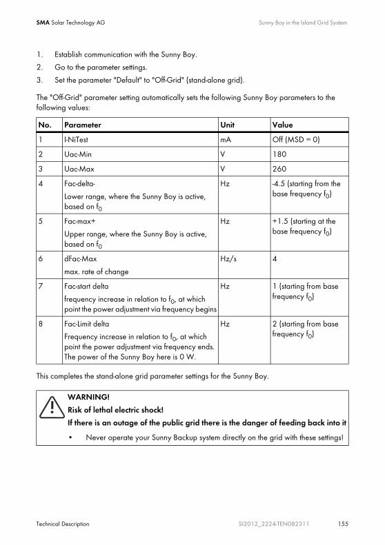
SMA Solar Technology AG Sunny Boy in the Island Grid System
Technical Description SI2012_2224-TEN082311 155
1. Establish communication with the Sunny Boy.
2. Go to the parameter settings.
3. Set the parameter "Default" to "Off-Grid" (stand-alone grid).
The "Off-Grid" parameter setting automatically sets the following Sunny Boy parameters to the following values:
This completes the stand-alone grid parameter settings for the Sunny Boy.
No. Parameter Unit Value
1 I-NiTest mA Off (MSD = 0)
2 Uac-Min V 180
3 Uac-Max V 260
4 Fac-delta-
Lower range, where the Sunny Boy is active, based on f0
Hz -4.5 (starting from the base frequency f0)
5 Fac-max+
Upper range, where the Sunny Boy is active, based on f0
Hz +1.5 (starting at the base frequency f0)
6 dFac-Max
max. rate of change
Hz/s 4
7 Fac-start delta
frequency increase in relation to f0, at which point the power adjustment via frequency begins
Hz 1 (starting from base frequency f0)
8 Fac-Limit delta
Frequency increase in relation to f0, at which point the power adjustment via frequency ends. The power of the Sunny Boy here is 0 W.
Hz 2 (starting from base frequency f0)
WARNING!
Risk of lethal electric shock!
If there is an outage of the public grid there is the danger of feeding back into it
• Never operate your Sunny Backup system directly on the grid with these settings!

Sunny Boy in the Island Grid System SMA Solar Technology AG
156 SI2012_2224-TEN082311 Technical Description
15.2 Frequency Shift Power Control (FSPC)This section describes how the power adjustment via frequency "Frequency Shift Power Control (FSPC)" functions.
If Sunny Boy inverters are connected to the AC output side of a stand-alone grid, the Sunny Island must be able to limit their output power. This situation can come about when, for example, the Sunny Island's batteries are fully charged and the (solar) power available from the PV generator exceeds the power required by the connected loads.
Using a Communication Bus
If the Sunny Boy and Sunny Island are operated together on one communication bus, the "250.06 ComBaud" parameter in the Sunny Island must be set to "1200" (default).
The Sunny Island only communicates through the SMA-Net protocol, Sunny-Net is not supported.
Settings in Older SMA Inverters
It may happen that older SMA inverters cannot yet be set to "Offgrid" (stand-alone grid) via the "Default" parameter. In this case, the values 1 - 6 in the table must be set individually.
FSPC
The frequency-based power control works only in stand-alone mode!
Inverters without FSPC
This function is neither supported by the SMA PV inverters SB2100TL, SB3300TL, SB4200TL and SB5000TL, nor by older models in the SWR series. But these Sunny Boys can nevertheless be used in island grid systems.
If the present battery voltage is higher than the nominal battery voltage (VBatt nom), the Sunny Boy inverters mentioned above are disconnected from the stand-alone grid present at that time, and are only reconnected after a battery discharge of at least 5 %.
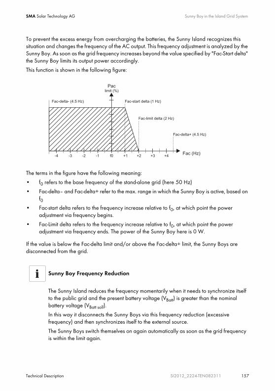
SMA Solar Technology AG Sunny Boy in the Island Grid System
Technical Description SI2012_2224-TEN082311 157
To prevent the excess energy from overcharging the batteries, the Sunny Island recognizes this situation and changes the frequency of the AC output. This frequency adjustment is analyzed by the Sunny Boy. As soon as the grid frequency increases beyond the value specified by "Fac-Start delta" the Sunny Boy limits its output power accordingly.
This function is shown in the following figure:
The terms in the figure have the following meaning:
• f0 refers to the base frequency of the stand-alone grid (here 50 Hz)
• Fac-delta– and Fac-delta+ refer to the max. range in which the Sunny Boy is active, based on f0
• Fac-start delta refers to the frequency increase relative to f0, at which point the power adjustment via frequency begins.
• Fac-Limit delta refers to the frequency increase relative to f0, at which point the power adjustment via frequency ends. The power of the Sunny Boy here is 0 W.
If the value is below the Fac-delta limit and/or above the Fac-delta+ limit, the Sunny Boys are disconnected from the grid.
Sunny Boy Frequency Reduction
The Sunny Island reduces the frequency momentarily when it needs to synchronize itself to the public grid and the present battery voltage (VBatt) is greater than the nominal battery voltage (VBatt soll).
In this way it disconnects the Sunny Boys via this frequency reduction (excessive frequency) and then synchronizes itself to the external source.
The Sunny Boys switch themselves on again automatically as soon as the grid frequency is within the limit again.
Maintenance and Care SMA Solar Technology AG
158 SI2012_2224-TEN082311 Technical Description
16 Maintenance and Care
16.1 EnclosureCheck to see that every device housing in the island grid system is mechanically sound. If damage (e.g. cracks, holes, missing covers) endangers the operating safety, the Sunny Island must be deactivated immediately.
Larger particles of dirt should be removed from the device with a soft brush, or similar object. Dust can be removed with a damp cloth. Solvents, abrasives or corrosive materials must not be used for cleaning!
16.2 The Sunny Island's Control Panel
16.3 Sunny Remote Control 1It is best to clean the control elements with a soft, damp cloth. Solvents, abrasives or corrosive materials must not be used for cleaning!
16.4 Functional TestCheck regularly whether error messages are present. If an error message is displayed for which you cannot identify any apparent cause, the stand-alone grid must be inspected by an installer. To ensure optimal operation, the operator should regularly check the Sunny Island's entries in the error list at short intervals (monthly, or even weekly), especially during the first months after commissioning. This can help to discover hidden faults in the installation or errors in the configuration.
NOTICE!
Unintended starting of the Sunny Island while cleaning the membrane keypad.
Only clean the membrane keypad when the device is deactivated.
NOTICE!
Unintended starting up of the device while cleaning the knob by accidentally depressing or turning it!
1. Switch off the device.
2. Clean the device.

SMA Solar Technology AG Maintenance and Care
Technical Description SI2012_2224-TEN082311 159
16.5 Battery
16.6 DisposalDispose of the devices at the end of their service life in accordance with the disposal regulations for electronic scrap which apply at the installation site at that time. Alternatively, send them back to the SMA Solar Technology AG with shipping paid by sender and labeled "FOR DISPOSAL"
(chapter 21 "Contact" (Page 201)).
Check the ground connection
Once a year, visually inspect the ground connection at the house connection box, or on the meter board between PEN and the equipotential bonding bar!
NOTICE!
Possible damage to the battery due to a lack of inspection and maintenance!
In this regard, observe the battery manufacturer's specifications.

Parameter List Overview SMA Solar Technology AG
160 SI2012_2224-TEN082311 Technical Description
17 Parameter List OverviewOverview of the menu area:
Main menu Submenu 1 Submenu 2
SMA Solar Technology AG Parameter List Overview
Technical Description SI2012_2224-TEN082311 161
Only parameters in the menu branches "200-Settings" and "500-Operation" can be changed. The other values are only shown on the display. The cells with a grey background in the following tables show all menu items that can only be changed after entering the installer password.
Fault-prone operation of the Sunny Island due to wrong parameter settings.
• Proceed carefully when setting parameters!
• Take note of the original values of all parameters that you change.
Saving settings onto the MMC/SD card
Once the system is working optimally, i.e., the selected settings have proven effective, save the selected values on the MMC/SD card using the "510.01 ParaSto" parameter (see chapter 10.4 "Saving Data onto a MMC/SD Card" (Page 107)).
Thereafter you can make new settings. If you choose to reject these settings again, you can restore the system to its previous state using the "510.02 ParaLod" parameter.
Labelling parameters
The parameter names used are based on the international IEC 61850-7-4 and 61400-25 Standards.
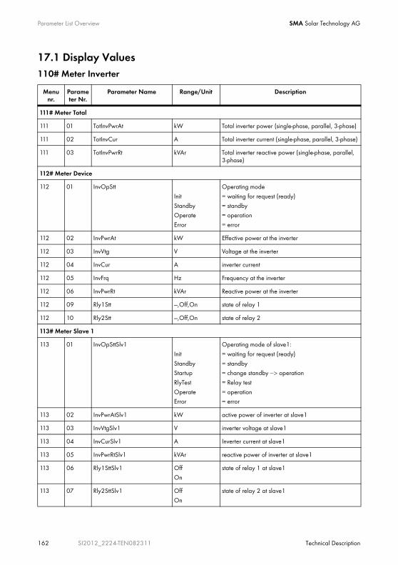
Parameter List Overview SMA Solar Technology AG
162 SI2012_2224-TEN082311 Technical Description
17.1 Display Values110# Meter Inverter
Menu nr.
Parameter Nr.
Parameter Name Range/Unit Description
111# Meter Total
111 01 TotInvPwrAt kW Total inverter power (single-phase, parallel, 3-phase)
111 02 TotInvCur A Total inverter current (single-phase, parallel, 3-phase)
111 03 TotInvPwrRt kVAr Total inverter reactive power (single-phase, parallel, 3-phase)
112# Meter Device
112 01 InvOpStt
Init
StandbyOperate
Error
Operating mode
= waiting for request (ready)
= standby= operation
= error
112 02 InvPwrAt kW Effective power at the inverter
112 03 InvVtg V Voltage at the inverter
112 04 InvCur A inverter current
112 05 InvFrq Hz Frequency at the inverter
112 06 InvPwrRt kVAr Reactive power at the inverter
112 09 Rly1Stt ---,Off,On state of relay 1
112 10 Rly2Stt ---,Off,On state of relay 2
113# Meter Slave 1
113 01 InvOpSttSlv1
Init
StandbyStartup
RlyTest
OperateError
Operating mode of slave1:
= waiting for request (ready)
= standby= change standby −> operation
= Relay test
= operation= error
113 02 InvPwrAtSlv1 kW active power of inverter at slave1
113 03 InvVtgSlv1 V inverter voltage at slave1
113 04 InvCurSlv1 A Inverter current at slave1
113 05 InvPwrRtSlv1 kVAr reactive power of inverter at slave1
113 06 Rly1SttSlv1 Off
On
state of relay 1 at slave1
113 07 Rly2SttSlv1 Off
On
state of relay 2 at slave1
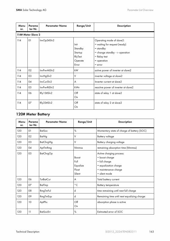
SMA Solar Technology AG Parameter List Overview
Technical Description SI2012_2224-TEN082311 163
120# Meter Battery
114# Meter Slave 2
114 01 InvOpSttSlv2Init
Standby
StartupRlyTest
Operate
Error
Operating mode of slave2:= waiting for request (ready)
= standby
= change standby −> operation= Relay test
= operation
= error
114 02 InvPwrAtSlv2 kW active power of inverter at slave2
114 03 InvVtgSlv2 V inverter voltage at slave2
114 04 InvCurSlv2 A Inverter current at slave2
114 05 InvPwrRtSlv2 kVAr reactive power of inverter at slave2
114 06 Rly1SttSlv2 Off
On
state of relay 1 at slave2
114 07 Rly2SttSlv2 Off
On
state of relay 2 at slave2
Menu nr.
Parameter Nr.
Parameter Name Range/Unit Description
120 01 BatSoc % Momentary state of charge of battery (SOC)
120 02 BatVtg V Battery voltage
120 03 BatChrgVtg V Battery charging voltage
120 04 AptTmRmg hhmmss remaining absorption time (hhmmss)
120 05 BatChrgOp
BoostFull
Equalize
FloatSilent
Active charging process:
= boost charge= full charge
= equalization charge
= maintenance charge= silent mode
120 06 TotBatCur A Total battery current
120 07 BatTmp °C Battery temperature
120 08 RmgTmFul d time remaining until next full charge
120 09 RmgTmEqu d Remaining time until next equalizing charge:
120 10 AptPhs Off
On
absorption phase is active
120 11 BatSocErr % Estimated error of SOC
Menu nr.
Parameter Nr.
Parameter Name Range/Unit Description
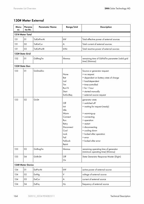
Parameter List Overview SMA Solar Technology AG
164 SI2012_2224-TEN082311 Technical Description
130# Meter External
Menu nr.
Parameter.Nr.
Parameter Name Range/Unit Description
131# Meter Total
131 01 TotExtPwrAt kW Total effective power of external sources
131 02 TotExtCur A Total current of external sources
131 03 TotExtPwrRt kVAr Total reactive power of external sources
132# State Grid
132 01 GdRmgTm hhmmss remaining time of GdValTm parameter (valid grid time) (hhmmss)
133# State Gen
133 01 GnDmdSrc
NoneBat
Lod
TimRun1h
Start
ExtSrcReq
Source or generator request:
= no request= dependent on battery state of charge
= load-dependent
= time-controlled= for 1 hour
= started manually
= external source request
133 02 GnStt
Off
InitIdle
Warm
ConnectRun
Retry
DisconnectCool
Lock
FailFailLock
Reinit
generator state:
= switched off
= waiting for request (ready)
= warming-up
= connecting= operation
= restart
= disconnecting= cooling down
= locked after operation
= error= locked after error
133 03 GnRmgTm hhmmss remaining operating time of generator (minimum operating time) (hhmmss)
133 04 GnRnStt Off
On
State Generator Response Master (DigIn)
134# Meter Device
134 01 ExtPwrAt kW active power of external source
134 02 ExtVtg V voltage of external source
134 03 ExtCur A current of external source
134 04 ExtFrq Hz frequency of external source
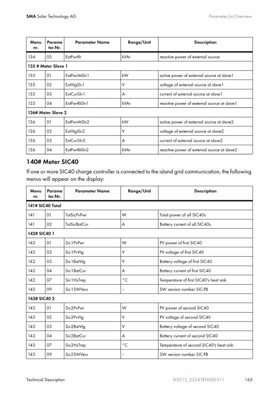
SMA Solar Technology AG Parameter List Overview
Technical Description SI2012_2224-TEN082311 165
140# Meter SIC40If one or more SIC40 charge controller is connected to the island grid communication, the following menus will appear on the display:
134 05 ExtPwrRt kVAr reactive power of external source
135 # Meter Slave 1
135 01 ExtPwrAtSlv1 kW active power of external source at slave1
135 02 ExtVtgSlv1 V voltage of external source at slave1
135 03 ExtCurSlv1 A current of external source at slave1
135 04 ExtPwrRtSlv1 kVAr reactive power of external source at slave1
136# Meter Slave 2
136 01 ExtPwrAtSlv2 kW active power of external source at slave2
136 02 ExtVtgSlv2 V voltage of external source at slave2
136 03 ExtCurSlv2 A current of external source at slave2
136 04 ExtPwrRtSlv2 kVAr reactive power of external source at slave2
Menu nr.
Parameter.Nr.
Parameter Name Range/Unit Description
141# SIC40 Total
141 01 TotSicPvPwr W Total power of all SIC40s
141 02 TotSicBatCur A Battery current of all SIC40s
142# SIC40 1
142 01 Sic1PvPwr W PV power of first SIC40
142 02 Sic1PvVtg V PV voltage of first SIC40
142 03 Sic1BatVtg V Battery voltage of first SIC40
142 04 Sic1BatCur A Battery current of first SIC40
142 07 Sic1HsTmp °C Temperature of first SIC40's heat sink
142 09 Sic1SWVers – SW version number SIC-PB
143# SIC40 2
143 01 Sic2PvPwr W PV power of second SIC40
143 02 Sic2PvVtg V PV voltage of second SIC40
143 03 Sic2BatVtg V Battery voltage of second SIC40
143 04 Sic2BatCur A Battery current of second SIC40
143 07 Sic2HsTmp °C Temperature of second SIC40's heat sink
143 09 Sic2SWVers – SW version number SIC-PB
Menu nr.
Parameter.Nr.
Parameter Name Range/Unit Description

Parameter List Overview SMA Solar Technology AG
166 SI2012_2224-TEN082311 Technical Description
For a detailed description of the "150# Meter Compact" menu see section 10.3.4 "Meter Compact" (Page 105).
17.2 Adjustable System Parameters
144# SIC40 3
144 01 Sic3PvPwr W PV power of third SIC40
144 02 Sic3PvVtg V PV voltage of third SIC40
144 03 Sic3BatVtg V Battery voltage of third SIC40
144 04 Sic3BatCur A Battery current of third SIC40
144 07 Sic3HsTmp °C Temperature of third SIC40's heat sink
144 09 Sic3SWVers – SW version number SIC-PB
145# SIC40 4
145 01 Sic4PvPwr W PV power of fourth SIC40
145 02 Sic4PvVtg V PV voltage of fourth SIC40
145 03 Sic4BatVtg V Battery voltage of fourth SIC40
145 04 Sic4BatCur A Battery current of fourth SIC40
145 07 Sic4HsTmp °C Temperature of fourth SIC40's heat sink
145 09 Sic4SWVers – SW version number SIC-PB
NOTICE!
Damage due to mistakenly entered values.
Directly after pressing the knob, operating values set this way can be changed. It could happen that wrong entries for these parameter values cannot be corrected quickly enough.
• Only qualified personnel should change and set system parameters.
• Parameters marked with (Stby) are to be changed only when the Sunny Island is in standby mode.
Menu nr.
Parameter.Nr.
Parameter Name Range/Unit Description

SMA Solar Technology AG Parameter List Overview
Technical Description SI2012_2224-TEN082311 167
210# Set Inverter
220# Set Battery
Changes to parameters
The cells with a grey background in the following tables show all menu items that can only be changed after entering the installer password.
All parameters can be set using a connected PC/laptop with the Sunny Data Control software, a Sunny WebBox or a Sunny Boy Control (see section 7.5 "Communication" (Page 53)).
Menu nr.
Parameter Nr.
Parameter Name Range/Unit Default value
Description
210 01 InvVtgNom V 230 Nominal inverter voltage
210 02 InvChrgCurMax A 9.6 Maximum AC charging current
210 03 InvFrqNom Hz 50 Nominal inverter frequency
Menu nr.
Parameter.Nr.
Parameter Name Range/Unit Default value
Description
221# Bat Property
221 01 BatTyp
VRLA
FLANiCd
VRLA Battery type:
= valve regulated lead acid
= flooded lead acid= nickel cadmium
can only be changed in QCG
221 02 BatCpyNom Ah 140 Nominal battery capacity (E:C10/U:C20)
can only be changed in QCG
221 03 BatVtgNom V 24 Nominal battery voltage
can only be changed in QCG
221 04 BatTmpMax degC 40 Maximum battery temperature
221 05 BatTmpStr degC 35 battery restart temperature following stop due to overtemperature
221 06 ChrgCtlOp Auto Type of DC charging device
222# Bat Chargemode
222 01 BatChrgCurMax A 80 Battery charging current limit (depends on nominal battery capacity), 60 % of the nominal battery capacity (221.02)

Parameter List Overview SMA Solar Technology AG
168 SI2012_2224-TEN082311 Technical Description
222 02 AptTmBoost min 120 Absorption time at normal charge
120 = VRLA
90 = FLA300 = NiCd
depending on the setting in QCG
222 03 AptTmFul h 5 Absorption time at full charge
5 = VRLA
5 = FLA7 = NiCd
depending on the setting in QCG
222 04 AptTmEqu h 10 Absorption time at equalizing charge
10 = VRLA
10 = FLA10 = NiCd
depending on the setting in QCG
222 05 CycTmFul d 14 Full charge cycle time
222 06 CycTmEqu d 180 Cycle time at equalizing charge
222 07 ChrgVtgBoost V 2.4 Setpoint of cell voltage at normal charge
2.4 = VRLA
2.55 = FLA1.65 = NiCd
depending on the setting in QCG
222 08 ChrgVtgFul V 2.4 Setpoint of cell voltage at full charge
2.4 = VRLA
2.5 = FLA1.65 = NiCd
depending on the setting in QCG
222 09 ChrgVtgEqu V 2.4 Setpoint of cell voltage at equalizing charge2.4 = VRLA
2.5 = FLA
1.65 = NiCddepending on the setting in QCG
222 10 ChrgVtgFlo V 2.25 Setpoint of cell voltage at floating charge2.25 = VRLA
2.25 = FLA
1.55 = NiCddepending on the setting in QCG
222 11 BatTmpCps mV/degC 4.0 Battery temperature compensation4.0 = VRLA
4.0 = FLA
0.0 = NiCddepending on the setting in QCG
Menu nr.
Parameter.Nr.
Parameter Name Range/Unit Default value
Description

SMA Solar Technology AG Parameter List Overview
Technical Description SI2012_2224-TEN082311 169
230# Set External
222 12 AutoEquChrgEna Disable
Enable
Enable activates automatic equalization charge
223# Bat Protection
223 01 BatPro1TmStr hhmmss 220000 time for starting battery preservation mode level 1
223 02 BatPro1TmStp hhmmss 060000 time for stopping battery preservation mode level 1
223 03 BatPro2TmStr hhmmss 170000 time for starting battery preservation mode level 2
223 04 BatPro2TmStp hhmmss 090000 time for stopping battery preservation mode level 2
223 05 BatPro1Soc % 20 SOC limit for preservation mode level 1
223 06 BatPro2Soc % 15 SOC limit for preservation mode level 2
223 07 BatPro3Soc % 10 SOC limit for preservation mode level 3
224# Bat Silentmode
224 01 SilentEna Disable
Enable
Disable Enable Silent mode on the grid
224 02 SilentTmFlo
(Stby)
h 3 max. time for float charge until change to silent
224 03 SilentTmMax
(Stby)
h 12 max. time for silent mode until transfer into float
225# Battery Current Sensor
225 01 BatCurSnsTyp - None
60mV
50mV
Current sensor type (60mV, 50mV)
225 02 BatCurGain60 A/60mV 3 external battery current sensor 60mV type
225 03 BatCurGain50 A/50mV 12 external battery current sensor 50mV type
225 04 BatCurAutoCal Start Automatic calibration of the external battery current sensor
Menu nr.
Parameter.Nr.
Parameter Name Range/Unit Default value
Description
231# Ext General
231 02 PvFeedTmStr hhmmss 040000 start of PV feed-in
231 03 PvFeedTmStp hhmmss 220000 stop of PV feed-in
231 04 ExtLkTm min 20 Locking time after Reverse Power and/or relay protection
Menu nr.
Parameter.Nr.
Parameter Name Range/Unit Default value
Description

Parameter List Overview SMA Solar Technology AG
170 SI2012_2224-TEN082311 Technical Description
231 09 ExtSrc Grid Grid Grid Operation
232# Grid Control
232 01 GdVtgMin V 189 Minimum grid voltage
232 02 GdVtgMax V 259.5 Maximum grid voltage
232 03 GdCurNom A 16 Nominal grid current
232 04 GdFrqNom Hz 50 Nominal frequency
232 05 GdFrqMin Hz 47.65 Minimum grid frequency
232 06 GdFrqMax Hz 50.15 Maximum grid frequency
232 07 GdVldTm sec 30 minimum time required for grid (voltage and frequency) to be within permissible range for connection
232 08 GdMod GridCharge
GridFeed
GridCharge Grid interface
232 09 GdRvPwr W 100 permissible grid reverse power (effective power)
232 10 GdRvTm sec 5 permissible time for grid reverse power
232 15 GdAISns Low,
Medium
standardHigh
standard AI sensitivity
233# Gen Control
233 01 GnVtgMin V 172.5 Min. generator voltage
233 02 GnVtgMax V 264.5 Max. generator voltage
233 03 GnCurNom A 25 Nominal generator current
233 04 GnFrqNom Hz 50 Nominal generator frequency (at nominal load)
230V_50HZ = 50
220V_60HZ = 60depending on the setting in QCG
233 05 GnFrqMin Hz 44.64 Minimum generator frequency230V_50HZ = 44.64
220V_60HZ = 50
depending on the setting in QCG
233 06 GnFrqMax Hz 60 Maximum generator frequency
230V_50HZ = 60220V_60HZ = 70
depending on the setting in QCG
Menu nr.
Parameter.Nr.
Parameter Name Range/Unit Default value
Description

SMA Solar Technology AG Parameter List Overview
Technical Description SI2012_2224-TEN082311 171
233 07 GnStrMod Manual
Automatic start
GenMan
Automatic start
Generator interface
233 08 GnOpTmMin min 15 Minimum generator operating time
233 09 GnStpTmMin min 15 Minimum generator stop time
233 10 GnCoolTm min 5 Cooling time for Generator
233 11 GnErrStpTm h 6 Generator stop time in case of generator failure
233 12 GnWarmTm sec 60 warm up time (minimum time required for generator voltage and frequency to be within permissible range for connection)
233 13 GnRvPwr W 100 allowable generator reverse power (active power)
233 14 GnRvTm sec 30 allowable time for reverse power/reverse current
233 15 GnCtlMod Cur
CurFrq
Cur External (Gen/Grid) control
(Current or frequency)
233 20 GnAISns Low,
Mediumstandard
High
standard AI sensitivity
234# Gen Start
234 01 GnAutoEna OffOn
On activate generator autostart
234 02 GnAutoStr 3 Number of automatic starts
234 03 GnSocTm1Str % 40 SOC limit for switching on generator for time 1
234 04 GnSocTm1Stp % 80 SOC limit for switching off generator for time 1
234 05 GnSocTm2Str % 40 SOC limit for switching on generator for time 2
234 06 GnSocTm2Stp % 80 SOC limit for switching off generator for time 2
234 07 GnTm1Str hhmmss 0 time 1 for generator request (begin time 1, end time 2) (hhmmss)
234 08 GnTm2Str hhmmss 0 time 2 for generator request (begin time 2, end time 1) (hhmmss)
234 09 GnPwrEna Off
On
Off activate generator request as a result of power
Menu nr.
Parameter.Nr.
Parameter Name Range/Unit Default value
Description

Parameter List Overview SMA Solar Technology AG
172 SI2012_2224-TEN082311 Technical Description
240# Set Relay
234 10 GnPwrStr kW 4 Generator request starting capacity
234 11 GnPwrStp kW 2 Generator request interrupting capacity
234 12 GnPwrAvgTm sec 60 average time for power-related generator start
Menu nr.
Parameter.Nr.
Parameter Name Range/Unit Default value
Description
241# Relay General
241 01 Rly1Op
OffOn
AutoGn
AutoLodExt
AutoLod1Soc
AutoLod2Soc
Tmr1
Tmr2
AptPhsGnRn
ExtVfOk
GdOn
Error
WarmRun
MSD 1
MSD 2BatFan
AcdCir
AutoGn Function of relay 1
= switched off= switched on
= automatic generator connection
= automatic disconnection of loads, connection only if external sources are available
= automatic connection/disconnection of loads due to SOC1= automatic connection/disconnection of loads due to SOC2= programmable timer1
= programmable timer1
= absorption phase is active= generator is running
= ext. voltage and frequency in permissible range
= ext. grid is connected
= error= warm-up
= operation
(= currently has no function)(= currently has no function)
= battery room fan
= electrolyte pump
241 02 Rly2Op see 241.01 AutoLodExt Function of relay 2
For details see 241.01
242# Relay Load
242 01 Lod1SocTm1Str % 30 SOC limit for load shedding 1 start for t1
242 02 Lod1SocTm1Stp % 50 SOC limit for load shedding 1 stop for t1
242 03 Lod1SocTm2Str % 30 SOC limit for load shedding 1 start for t2
242 04 Lod1SocTm2Stp % 50 SOC limit for load shedding 1 stop for t2
Menu nr.
Parameter.Nr.
Parameter Name Range/Unit Default value
Description
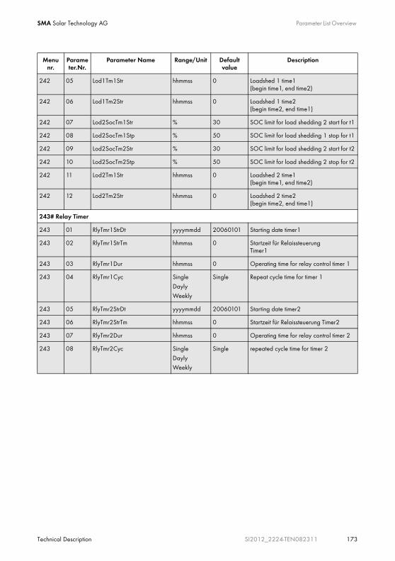
SMA Solar Technology AG Parameter List Overview
Technical Description SI2012_2224-TEN082311 173
242 05 Lod1Tm1Str hhmmss 0 Loadshed 1 time1 (begin time1, end time2)
242 06 Lod1Tm2Str hhmmss 0 Loadshed 1 time2 (begin time2, end time1)
242 07 Lod2SocTm1Str % 30 SOC limit for load shedding 2 start for t1
242 08 Lod2SocTm1Stp % 50 SOC limit for load shedding 1 stop for t1
242 09 Lod2SocTm2Str % 30 SOC limit for load shedding 2 start for t2
242 10 Lod2SocTm2Stp % 50 SOC limit for load shedding 2 stop for t2
242 11 Lod2Tm1Str hhmmss 0 Loadshed 2 time1 (begin time1, end time2)
242 12 Lod2Tm2Str hhmmss 0 Loadshed 2 time2 (begin time2, end time1)
243# Relay Timer
243 01 RlyTmr1StrDt yyyymmdd 20060101 Starting date timer1
243 02 RlyTmr1StrTm hhmmss 0 Startzeit für RelaissteuerungTimer1
243 03 RlyTmr1Dur hhmmss 0 Operating time for relay control timer 1
243 04 RlyTmr1Cyc Single
Dayly
Weekly
Single Repeat cycle time for timer 1
243 05 RlyTmr2StrDt yyyymmdd 20060101 Starting date timer2
243 06 RlyTmr2StrTm hhmmss 0 Startzeit für Relaissteuerung Timer2
243 07 RlyTmr2Dur hhmmss 0 Operating time for relay control timer 2
243 08 RlyTmr2Cyc Single
DaylyWeekly
Single repeated cycle time for timer 2
Menu nr.
Parameter.Nr.
Parameter Name Range/Unit Default value
Description

Parameter List Overview SMA Solar Technology AG
174 SI2012_2224-TEN082311 Technical Description
244# Relay Slave1
244 01 Rly1OpSlv1 Off function of relay 1 on slave1
Off = switched off
On = switched on
AutoGn = automatic generator connection
AutoLodExt = automatic disconnection of loads, connection only if external sources are available
AutoLod1Soc = automatic connection/disconnection of loads due to SOC1
AutoLod2Soc = automatic connection/disconnection of loads due to SOC2
Tmr1 = programmable timer1
Tmr2 = programmable timer2
AptPhs = absorption phase is active
GnRn = generator is running
ExtVfOk = ext. voltage and frequency in permissible range
GdOn = ext. grid is connected
Error = error
Warm = warm-up
Run = operation
BatFan Battery room fan
AcdCir = electrolyte pump
Menu nr.
Parameter.Nr.
Parameter Name Range/Unit Default value
Description

SMA Solar Technology AG Parameter List Overview
Technical Description SI2012_2224-TEN082311 175
244 02 Rly2OpSlv1 Off function of relay 2 on slave1
Off = switched off
On = switched on
AutoGn = automatic generator connection
AutoLodExt = automatic disconnection of loads, connection only if external sources are available
AutoLod1Soc = automatic connection/disconnection of loads due to SOC1
AutoLod2Soc = automatic connection/disconnection of loads due to SOC2
Tmr1 = programmable timer1
Tmr2 = programmable timer2
AptPhs = absorption phase is active
GnRn = generator is running
ExtVfOk = ext. voltage and frequency in permissible range
GdOn = ext. grid is connected
Error = error
Warm = warm-up
Run = operation
BatFan Battery room fan
AcdCir = electrolyte pump
Menu nr.
Parameter.Nr.
Parameter Name Range/Unit Default value
Description

Parameter List Overview SMA Solar Technology AG
176 SI2012_2224-TEN082311 Technical Description
245# Relay Slave2
245 01 Rly1OpSlv2 Off function of relay 1 on slave2
Off = switched off
On = switched on
AutoGn = automatic generator connection
AutoLodExt = automatic disconnection of loads, connection only if external sources are available
AutoLod1Soc = automatic connection/disconnection of loads due to SOC1
AutoLod2Soc = automatic connection/disconnection of loads due to SOC2
Tmr1 = programmable timer1
Tmr2 = programmable timer2
AptPhs = absorption phase is active
GnRn = generator is running
ExtVfOk = ext. voltage and frequency in permissible range
GdOn = ext. grid is connected
Error = error
Warm = warm-up
Run = operation
BatFan Battery room fan
AcdCir = electrolyte pump
Menu nr.
Parameter.Nr.
Parameter Name Range/Unit Default value
Description

SMA Solar Technology AG Parameter List Overview
Technical Description SI2012_2224-TEN082311 177
245 02 Rly2OpSlv2 Off function of relay 2 on slave2
Off = switched off
On = switched on
AutoGn = automatic generator connection
AutoLodExt = automatic disconnection of loads, connection only if external sources are available
AutoLod1Soc = automatic connection/disconnection of loads due to SOC1
AutoLod2Soc = automatic connection/disconnection of loads due to SOC2
Tmr1 = programmable timer1
Tmr2 = programmable timer2
AptPhs = absorption phase is active
GnRn = generator is running
ExtVfOk = ext. voltage and frequency in permissible range
GdOn = ext. grid is connected
Error = error
Warm = warm-up
Run = operation
BatFan Battery room fan
AcdCir = electrolyte pump
Menu nr.
Parameter.Nr.
Parameter Name Range/Unit Default value
Description
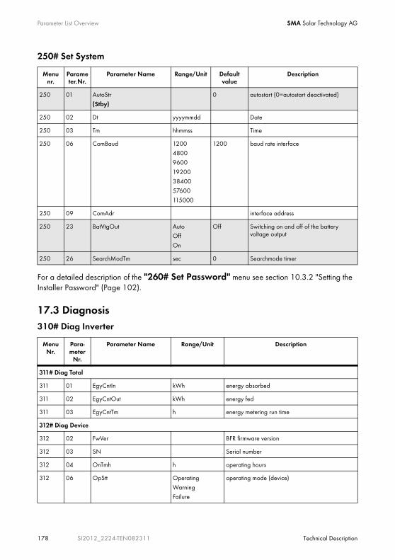
Parameter List Overview SMA Solar Technology AG
178 SI2012_2224-TEN082311 Technical Description
250# Set System
For a detailed description of the "260# Set Password" menu see section 10.3.2 "Setting the Installer Password" (Page 102).
17.3 Diagnosis310# Diag Inverter
Menu nr.
Parameter.Nr.
Parameter Name Range/Unit Default value
Description
250 01 AutoStr
(Stby)0 autostart (0=autostart deactivated)
250 02 Dt yyyymmdd Date
250 03 Tm hhmmss Time
250 06 ComBaud 1200
48009600
19200
3840057600
115000
1200 baud rate interface
250 09 ComAdr interface address
250 23 BatVtgOut AutoOff
On
Off Switching on and off of the battery voltage output
250 26 SearchModTm sec 0 Searchmode timer
Menu Nr.
Para-meter
Nr.
Parameter Name Range/Unit Description
311# Diag Total
311 01 EgyCntIn kWh energy absorbed
311 02 EgyCntOut kWh energy fed
311 03 EgyCntTm h energy metering run time
312# Diag Device
312 02 FwVer BFR firmware version
312 03 SN Serial number
312 04 OnTmh h operating hours
312 06 OpStt Operating
WarningFailure
operating mode (device)
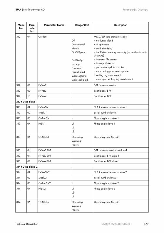
SMA Solar Technology AG Parameter List Overview
Technical Description SI2012_2224-TEN082311 179
312 07 CardSttOff
Operational
MountOutOfSpace
BadFileSysIncomp
Parameter
ParamFailedWriteLogData
WriteLogFailed
MMC/SD card status message:= no Sunny Island
= in operation
= card initializing= insufficient memory capacity (on card or in main directory)= incorrect file system
= incompatible card
= parameter update is active= error during parameter update
= writing log data to card
= error upon writing log data to card
312 08 FwVer2 DSP firmware version
312 09 FwVer3 Boot loader BFR
312 10 FwVer4 Boot loader DSP
313# Diag Slave 1
313 01 FwVerSlv1 BFR firmware version on slave1
313 02 SNSlv1 Serial number slave1
313 03 OnTmhSlv1 h Operating hours slave1
313 04 PhSlv1 L1
L2L3
Phase angle slave 1
313 05 OpSttSlv1 OperatingWarning
Failure
Operating state Slave2
313 06 FwVer2Slv1 DSP firmware version on slave1
313 07 FwVer3Slv1 Boot loader BFR slave 1
313 08 FwVer4Slv1 Boot loader DSP slave 1
314# Diag Slave 2
314 01 FwVerSlv2 BFR firmware version on slave2
314 02 SNSlv2 Serial number slave2
314 03 OnTmhSlv2 h Operating hours slave2
314 04 PhSlv2 L1L2
L3
Phase angle slave 2
314 05 OpSttSlv2 Operating
Warning
Failure
Operating state Slave2
Menu Nr.
Para-meter
Nr.
Parameter Name Range/Unit Description
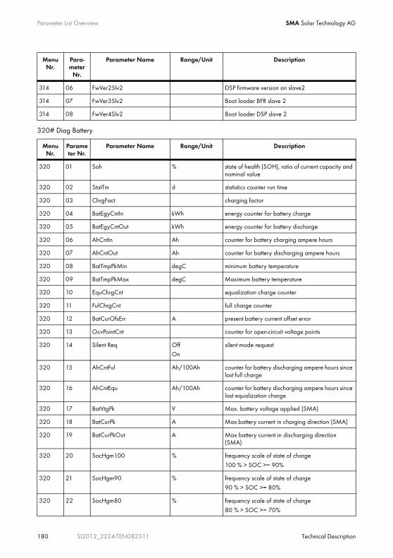
Parameter List Overview SMA Solar Technology AG
180 SI2012_2224-TEN082311 Technical Description
320# Diag Battery
314 06 FwVer2Slv2 DSP firmware version on slave2
314 07 FwVer3Slv2 Boot loader BFR slave 2
314 08 FwVer4Slv2 Boot loader DSP slave 2
Menu Nr.
Parameter Nr.
Parameter Name Range/Unit Description
320 01 Soh % state of health (SOH), ratio of current capacity and nominal value
320 02 StatTm d statistics counter run time
320 03 ChrgFact charging factor
320 04 BatEgyCntIn kWh energy counter for battery charge
320 05 BatEgyCntOut kWh energy counter for battery discharge
320 06 AhCntIn Ah counter for battery charging ampere hours
320 07 AhCntOut Ah counter for battery discharging ampere hours
320 08 BatTmpPkMin degC minimum battery temperature
320 09 BatTmpPkMax degC Maximum battery temperature
320 10 EquChrgCnt equalization charge counter
320 11 FulChrgCnt full charge counter
320 12 BatCurOfsErr A present battery current offset error
320 13 OcvPointCnt counter for open-circuit voltage points
320 14 Silent Req OffOn
silent mode request
320 15 AhCntFul Ah/100Ah counter for battery discharging ampere hours since last full charge
320 16 AhCntEqu Ah/100Ah counter for battery discharging ampere hours since last equalization charge
320 17 BatVtgPk V Max. battery voltage applied (SMA)
320 18 BatCurPk A Max.battery current in charging direction (SMA)
320 19 BatCurPkOut A Max battery current in discharging direction (SMA)
320 20 SocHgm100 % frequency scale of state of charge
100 % > SOC >= 90%
320 21 SocHgm90 % frequency scale of state of charge
90 % > SOC >= 80%
320 22 SocHgm80 % frequency scale of state of charge
80 % > SOC >= 70%
Menu Nr.
Para-meter
Nr.
Parameter Name Range/Unit Description

SMA Solar Technology AG Parameter List Overview
Technical Description SI2012_2224-TEN082311 181
330# Diag External
320 23 SocHgm70 % frequency scale of state of charge
70 % > SOC >= 60%
320 24 SocHgm60 % frequency scale of state of charge
60 % > SOC >= 50%
320 25 SocHgm50 % frequency scale of state of charge
50 % > SOC >= 40%
320 26 SocHgm40 % frequency scale of state of charge
40 % > SOC >= 30%
320 27 SocHgm30 % frequency scale of state of charge
30 % > SOC >= 20%
320 28 SocHgm20 % frequency scale of state of charge
20 % > SOC >= 10%
320 29 SocHgm10 % frequency scale of state of charge
10 % > SOC >= 0%
320 30 SocHgm000 % frequency scale of state of charge
SOC < 0 %
320 31 SocVtgCal % re-calibration of state of charge only via open-circuit voltage
320 32 ErrSocVtgCal % estimated error of voltage calibrated state of charge
320 33 SocChrgCal % re-calibration of state of charge only via full charge
320 34 ErrSocChrgCal % estimated error of full-charge calibrated state of charge
320 35 OcvGra Ah/V rise of open-circuit voltage characteristic curve
320 36 OcvMax V max. open-circuit voltage
Menu Nr.
Parameter Nr.
Parameter Name Range/Unit Description
331# Diag Grid
331 01 GdEgyCntIn kWh energy counter for grid-feed-in
331 02 GdEgyCntOut kWh energy meter for power taken from the grid
331 03 GdEgyTmh h run time of grid energy counter
331 04 GdOpTmh h Operating hour counter for grid operation
331 05 GdCtcCnt Counter for grid connections
332# Diag Generator
332 01 GnEgyCnt kWh generator energy counter
332 02 GnEgyTm h run time of generator energy counter
Menu Nr.
Parameter Nr.
Parameter Name Range/Unit Description

Parameter List Overview SMA Solar Technology AG
182 SI2012_2224-TEN082311 Technical Description
17.4 Events, Warnings and Failures (History)Events and failure messages [410# (Fail Current), 420# (Fail History) and 430# (Event History)] are described in section 18.4 "Display of Failures and Events" (Page 184).
17.5 Functions During Operation510# Oper Inverter
520# Oper Battery
332 03 GnOpTmh h Counter for generator operating hours
332 04 GnStrCnt - Number of generator starts
Menu nr.
Parameter.Nr.
Parameter Name Range/Unit Default value
Description
510 01 InvRs
(Stby)Restart --- triggers inverter reset
510 02 InvTmOpEna DisableEnable
Disable activates time-controlled inverter operation
510 03 InvTmOpStrDt yyyymmdd 20060101 Starting date for time-controlled inverter operation
510 04 InvTmOpStrTm hhmmss 0 Start time for time-controlled inverter operation
510 05 InvTmOpRnDur hhmmss 0 Run time for time-controlled inverter operation
510 06 InvTmOpCyc SingleDayly
Weekly
Single Repeat cycle time for timer 1
510 07 CntRs Inv
Bat
GnGd
All
--- Reset selected energy counter
Menu nr.
Parameter.Nr.
Name Range/Unit Default Description
520 01 ManChrgSel IdleStart
Stop
Idle triggers equalization charge (manual)
Menu Nr.
Parameter Nr.
Parameter Name Range/Unit Description

SMA Solar Technology AG Parameter List Overview
Technical Description SI2012_2224-TEN082311 183
540# Oper Generator
550# Oper SD-Card
For a detailed description of the 600 „Direct Access“ menu see section 10.3.3 "Accessing Parameters Directly" (Page 105).
Menu nr.
Parameter.Nr.
Parameter Name Range/Unit Default value
Description
540 01 GnManStr Auto
Stop
StartRun1h
ManEquChrg
Auto Manual generator start
540 02 GnAck Ackn Generator failure acknowledgment
Menu nr.
Parameter.Nr.
Name Range/Unit Default Description
550 01 ParaSto Set1
Set2
Set1 Save parameter settings
550 02 ParaLod Set1
Set2
Factory
Set1 Load parameter settings
550 03 CardFunc
ForcedWriteStoEvtHis
StoFailHis
functions for MMC/SD card
= forces writing of data= writes event list
= writes failure list
550 04 DatLogEna Off
On
On activates automatic data storage
Troubleshooting/Problem Solving SMA Solar Technology AG
184 SI2012_2224-TEN082311 Technical Description
18 Troubleshooting/Problem SolvingIn general the Sunny Island distinguishes between events and failures. These messages are shown on the Sunny Remote Control 1 display.
• Events describe state changes or transient states (e.g. generator connection).
• Errors describe impermissible or only limitedly permissible states. This includes, warnings, failures and errors. These normally require user interaction.
18.1 Error ConfirmationIf there is an error or fault, the Sunny Island goes into standby.
Proceed as follows to acknowledge and remove an error message:
1. Remove the cause.
2. Acknowledge and confirm the error message by pressing the knob on the Sunny Remote Control 1.
3. Start the Sunny Island again.
18.2 Handling AutostartThe Sunny Island has an autostart counter which counts down by 1 with every automatic start. After 10 minutes of normal operation of the Sunny Island, the autostart counter is set back to its original value.
If another fault occurs when the autostart meter is at 0, the Sunny Island waits for 10 minutes and then attempts to restart. The autostart counter starts again.
The number of autostarts allowed can be set using the "250.01 AutoStr" parameter (in standby mode).
18.3 Handling Failures Present During StartupDuring the booting procedure, all pending errors are generally confirmed without an entry being made in the history (see. menu "400 Failure/Event). Any errors still present after that are entered again after booting.
The Sunny Remote Control 1 shows:
• "Arrive" - the Sunny Island has recognized a fault (again) and has entered it in the list.
• "Clear" - the source of the fault has been cleared and the fault is "gone".
18.4 Display of Failures and EventsEvery error and every event is labeled distinctively and placed according to the Parameter/Measured value classification.
The message has four characters and is made up of one letter and three digits.
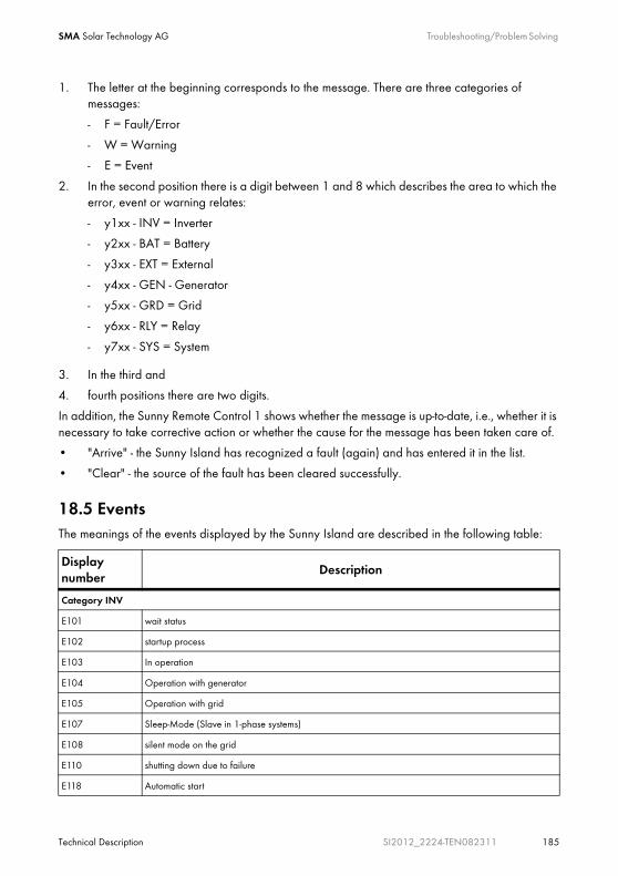
SMA Solar Technology AG Troubleshooting/Problem Solving
Technical Description SI2012_2224-TEN082311 185
1. The letter at the beginning corresponds to the message. There are three categories of messages:
- F = Fault/Error
- W = Warning
- E = Event
2. In the second position there is a digit between 1 and 8 which describes the area to which the error, event or warning relates:
- y1xx - INV = Inverter
- y2xx - BAT = Battery
- y3xx - EXT = External
- y4xx - GEN - Generator
- y5xx - GRD = Grid
- y6xx - RLY = Relay
- y7xx - SYS = System
3. In the third and
4. fourth positions there are two digits.
In addition, the Sunny Remote Control 1 shows whether the message is up-to-date, i.e., whether it is necessary to take corrective action or whether the cause for the message has been taken care of.
• "Arrive" - the Sunny Island has recognized a fault (again) and has entered it in the list.
• "Clear" - the source of the fault has been cleared successfully.
18.5 EventsThe meanings of the events displayed by the Sunny Island are described in the following table:
Display number
Description
Category INV
E101 wait status
E102 startup process
E103 In operation
E104 Operation with generator
E105 Operation with grid
E107 Sleep-Mode (Slave in 1-phase systems)
E108 silent mode on the grid
E110 shutting down due to failure
E118 Automatic start
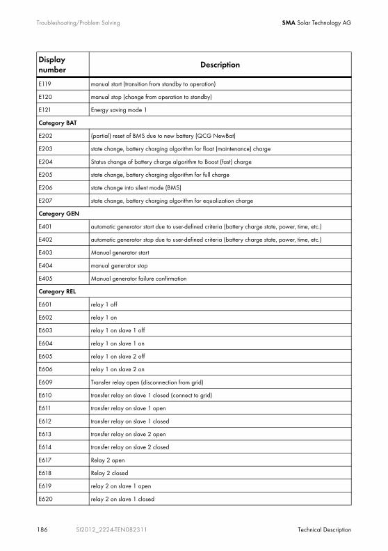
Troubleshooting/Problem Solving SMA Solar Technology AG
186 SI2012_2224-TEN082311 Technical Description
E119 manual start (transition from standby to operation)
E120 manual stop (change from operation to standby)
E121 Energy saving mode 1
Category BAT
E202 (partial) reset of BMS due to new battery (QCG NewBat)
E203 state change, battery charging algorithm for float (maintenance) charge
E204 Status change of battery charge algorithm to Boost (fast) charge
E205 state change, battery charging algorithm for full charge
E206 state change into silent mode (BMS)
E207 state change, battery charging algorithm for equalization charge
Category GEN
E401 automatic generator start due to user-defined criteria (battery charge state, power, time, etc.)
E402 automatic generator stop due to user-defined criteria (battery charge state, power, time, etc.)
E403 Manual generator start
E404 manual generator stop
E405 Manual generator failure confirmation
Category REL
E601 relay 1 off
E602 relay 1 on
E603 relay 1 on slave 1 off
E604 relay 1 on slave 1 on
E605 relay 1 on slave 2 off
E606 relay 1 on slave 2 on
E609 Transfer relay open (disconnection from grid)
E610 transfer relay on slave 1 closed (connect to grid)
E611 transfer relay on slave 1 open
E612 transfer relay on slave 1 closed
E613 transfer relay on slave 2 open
E614 transfer relay on slave 2 closed
E617 Relay 2 open
E618 Relay 2 closed
E619 relay 2 on slave 1 open
E620 relay 2 on slave 1 closed
Display number
Description

SMA Solar Technology AG Troubleshooting/Problem Solving
Technical Description SI2012_2224-TEN082311 187
E621 relay 2 on slave 2 open
E622 relay 2 on slave 2 closed
E625 digital input OFF (low)
E626 digital input ON (high)
E627 Digital Input Slave 1 to OFF (low) (not active)
E628 Digital Input Slave 1 to ON (High) (not active)
E629 Digital Input Slave 2 to OFF (low) (not active)
E630 Digital Input Slave 2 to ON (High) (not active)
Category SYS
E705 device start
E706 Set Date Time (Recording is done with "old" time)
E707 new system configured in the QCG
E708 Part 1 of the firmware updated (entry of the "old" version)
E709 Part 2 of the firmware updated (entry of the "old" version)
E711 MMC/SD card inserted
E712 Sunny Remote Control 1: parameter update
E715 Sunny Remote Control 1 activated
E851 First SIC40 has been detected
E852 Second SIC40 has been detected
E853 Third SIC40 has been detected
E854 Fourth SIC40 has been detected
Display number
Description
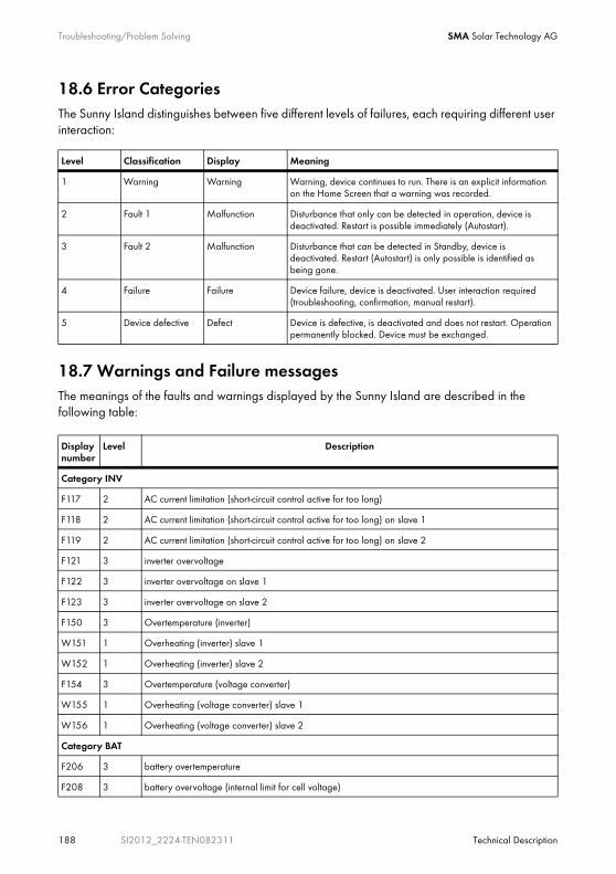
Troubleshooting/Problem Solving SMA Solar Technology AG
188 SI2012_2224-TEN082311 Technical Description
18.6 Error CategoriesThe Sunny Island distinguishes between five different levels of failures, each requiring different user interaction:
18.7 Warnings and Failure messagesThe meanings of the faults and warnings displayed by the Sunny Island are described in the following table:
Level Classification Display Meaning
1 Warning Warning Warning, device continues to run. There is an explicit information on the Home Screen that a warning was recorded.
2 Fault 1 Malfunction Disturbance that only can be detected in operation, device is deactivated. Restart is possible immediately (Autostart).
3 Fault 2 Malfunction Disturbance that can be detected in Standby, device is deactivated. Restart (Autostart) is only possible is identified as being gone.
4 Failure Failure Device failure, device is deactivated. User interaction required (troubleshooting, confirmation, manual restart).
5 Device defective Defect Device is defective, is deactivated and does not restart. Operation permanently blocked. Device must be exchanged.
Display number
Level Description
Category INV
F117 2 AC current limitation (short-circuit control active for too long)
F118 2 AC current limitation (short-circuit control active for too long) on slave 1
F119 2 AC current limitation (short-circuit control active for too long) on slave 2
F121 3 inverter overvoltage
F122 3 inverter overvoltage on slave 1
F123 3 inverter overvoltage on slave 2
F150 3 Overtemperature (inverter)
W151 1 Overheating (inverter) slave 1
W152 1 Overheating (inverter) slave 2
F154 3 Overtemperature (voltage converter)
W155 1 Overheating (voltage converter) slave 1
W156 1 Overheating (voltage converter) slave 2
Category BAT
F206 3 battery overtemperature
F208 3 battery overvoltage (internal limit for cell voltage)

SMA Solar Technology AG Troubleshooting/Problem Solving
Technical Description SI2012_2224-TEN082311 189
W210 1 Warning Battery overvoltage (dependent upon charge voltage setpoint value)
W211 1 insufficient battery temperature warning
W212 1 high battery temperature warning
Category EXT
W309 1 relay protection
W310 1 relay protection on slave 1
W311 1 relay protection on slave 2
W315 1 Disconnection from grid/generator, external voltage too low
W316 1 Disconnection from grid/generator, external voltage too low slave 1
W317 1 Disconnection from grid/generator, external voltage too low slave 2
W319 1 Disconnection from grid/generator, external voltage too high
W320 1 Disconnection from grid/generator, external voltage too high slave 1
W321 1 Disconnection from grid/generator, external voltage too high slave 2
W323 1 Disconnection from grid/generator, external frequency too low
W324 1 Disconnection from grid/generator, external frequency too low slave 1
W325 1 Disconnection from grid/generator, external frequency too low slave 2
W327 1 Disconnection from grid/generator, external frequency too high
W328 1 Disconnection from grid/generator, external frequency too high slave 1
W329 1 Disconnection from grid/generator, external frequency too high slave 2
W331 1 Disconnection from grid due to anti-islanding (unintended island grid)
W332 1 Disconnection from grid due to anti-islanding (unintended island grid) slave 1
W333 1 Disconnection from grid due to anti-islanding (unintended island grid) slave 2
W335 1 disconnection from grid/generator due to violation of voltage limits
W339 1 Disconnection from grid/generator, voltage rise protection
W340 1 Disconnection from grid/generator, voltage rise protection slave 1
W341 1 Disconnection from grid/generator, voltage rise protection slave 2
W360 1 Disconnection from grid due to excessive current
W361 1 Disconnection from grid due to excessive current slave 1
W362 1 Disconnection from grid due to excessive current slave 2
Categroy RLY
F605 4 Transfer relay does not open
F606 4 Transfer relay does not open slave 1
F607 4 Transfer relay does not open slave 2
Display number
Level Description

Troubleshooting/Problem Solving SMA Solar Technology AG
190 SI2012_2224-TEN082311 Technical Description
Category SYS
W702 1 internal restart
F703 3 Time limit exceeded during internal processing
F704 4 DSP invalid calibration
F705 4 Watchdog DSP triggered
F706 4 watchdog meter has expired (watchdog triggered several times in succession)
F707 4 watchdog meter on slave 1 has expired (watchdog triggered several times in succession)
F708 4 watchdog meter on slave 2 has expired (watchdog triggered several times in succession)
F709 4 watchdog meter on slave 3 has expired (watchdog triggered several times in succession)
F710 4 autostart counter expired (several autostarts in succession)
F711 2 DSP hardware error
F712 2 internal monitoring electronics (HTSS error)
W713 1 watchdog triggered
F714 2 internal overvoltage
F722 3 Short circuit in battery temperature sensor
F723 3 Defective cable in battery temperature sensor
W738 1 Synchronization was not conducted
F739 3 internal device communication BFR-DSP missing
F740 3 internal device communication BFR-DSP missing on slave 1
F741 3 internal device communication BFR-DSP missing on slave 2
F743 3 internal device communication BFR-DSP missing
W753 1 Invalid date (date is set automatically when launched)
W755 1 Battery preservation mode level 1
W756 1 Battery preservation mode level 2
W757 1 Battery preservation mode level 3
F762 4 Short circuit or ruptured cable on transformer temperature
F766 4 Short circuit or ruptured cable on transformer temperature sensor/inverter
W770 1 Short circuit at the 24 V DC-output
W851 1 Battery connection polarity reversed or short-circuit at first SIC40
W852 1 Battery excess voltage (>65 V) at first SIC40
W853 1 PV generator excess voltage at first SIC40
W854 1 PV voltage absent or short-circuit at first SIC40
W855 1 Sensor fault or temperature deficit at first SIC40
Display number
Level Description
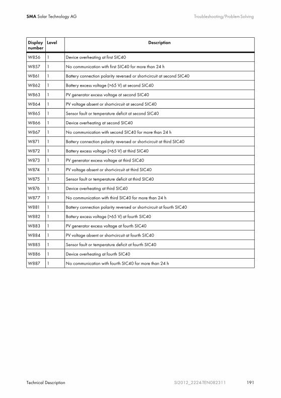
SMA Solar Technology AG Troubleshooting/Problem Solving
Technical Description SI2012_2224-TEN082311 191
W856 1 Device overheating at first SIC40
W857 1 No communication with first SIC40 for more than 24 h
W861 1 Battery connection polarity reversed or short-circuit at second SIC40
W862 1 Battery excess voltage (>65 V) at second SIC40
W863 1 PV generator excess voltage at second SIC40
W864 1 PV voltage absent or short-circuit at second SIC40
W865 1 Sensor fault or temperature deficit at second SIC40
W866 1 Device overheating at second SIC40
W867 1 No communication with second SIC40 for more than 24 h
W871 1 Battery connection polarity reversed or short-circuit at third SIC40
W872 1 Battery excess voltage (>65 V) at third SIC40
W873 1 PV generator excess voltage at third SIC40
W874 1 PV voltage absent or short-circuit at third SIC40
W875 1 Sensor fault or temperature deficit at third SIC40
W876 1 Device overheating at third SIC40
W877 1 No communication with third SIC40 for more than 24 h
W881 1 Battery connection polarity reversed or short-circuit at fourth SIC40
W882 1 Battery excess voltage (>65 V) at fourth SIC40
W883 1 PV generator excess voltage at fourth SIC40
W884 1 PV voltage absent or short-circuit at fourth SIC40
W885 1 Sensor fault or temperature deficit at fourth SIC40
W886 1 Device overheating at fourth SIC40
W887 1 No communication with fourth SIC40 for more than 24 h
Display number
Level Description
Troubleshooting/Problem Solving SMA Solar Technology AG
192 SI2012_2224-TEN082311 Technical Description
18.8 TroubleshootingQuestions that may be raised in practice are answered below:
Why does the Sunny Island not connect to the running generator?
• Check the generator fuses.
• Has the power allowed to be fed back into the generator during the permissible time been exceeded ("233.14 GnRvTm" parameter)? If so, "!" appears in the display. Generator connection is blocked for the time set. Set the "540.02 GnAck" parameter to Ackn.
• If the generator control relay (GnReq) is open:Has the generator been started manually ("233.07 GnStrMod" parameter)? Change the setting here to autostart, if required.
Why is the display of the Sunny Remote Control 1 dark and why is nothing displayed?
• Is the communication cable connected, and did both RJ45 plugs snap into their sockets audibly?
• Has the BatFuse (external DC fuse) been actuated?
The Sunny Island is disconnected from the battery this way and has switched off. Replace the DC fuses.
• Is the BatFuse functional?
In this case the device has switched off to protect the batteries from deep discharge (see also section 12.3 "Charge State/SOC and SOH" (Page 121)). To restart the Sunny Island, see section 10.1.5 "Restarting the System after Automatic Shutdown" (Page 88).
Why is it not possible to change parameters?
• Has the installer password been entered correctly? Check whether you are actually in "Installer Level" (see section 10.3.2 "Setting the Installer Password" (Page 102)). If necessary, repeat the calculation and entry of the password.
• You are in the "100-Meters" (Measuring data) menu or the "300-Diagnose" (Diagnosis) menu. The data values shown here can only be read.
• Some parameters can only be changed in standby mode or in the QCG (see e.g. the "233.07 GnStrMod" parameter in section 17.2 "Adjustable System Parameters" (Page 166)). Stop the Sunny Island as described in section 10.1.2 "Stopping" (Page 85). Note that this causes a dropout in the stand-alone grid and the loads are no longer supplied.
Why does the Sunny Island connect to the running generator only for a short time?
• The limits for the maximum permissible AC voltage or the minimum permissible frequency of the generator are too strict (parameter in menu "233 Generator Control"). Change voltage and/or frequency limits while observing the technical data for your generator.
SMA Solar Technology AG Troubleshooting/Problem Solving
Technical Description SI2012_2224-TEN082311 193
What happens if battery cell becomes useless?
• Remove the unusable cell from your battery bank. Start the Sunny Island and change the battery voltage in the QCG under "New Battery".
What can I do if the QCG does not start?
• Switch off the Sunny Island (see section 10.1.3 "Switching Off" (Page 87)) and restart it (see section 10.1.1 "Switching On/Starting" (Page 83)).
What happens when "MMC operation failed" is displayed?
• You wanted to perform an action using the MMC/SD card, but it failed (see section 10.2.6 "Selecting Warnings and Faults" (Page 100)). Check the card (on your PC/laptop) and use a new MMC/SD card, if necessary.
• Format the MMC/SD card using FAT16.
Why is the battery discharging even though the generator is running?
• The power produced by the generator does not reach the Sunny Island. Check the voltage and frequency values. It is possible that the generator fuses have been triggered.
• The energy produced by the generator is not enough to supply the consumers. The generator and the battery supply the consumers.
Why is the deactivation defined by the SOC in case of a full or equalization charge and generator start in the second time zone?
• Equalization charge has a higher priority than silent time.
Why is the SOC not at 100 % even after full charging has been completed?
• Define a longer period of time of absorption.
How is it possible to ensure that the maximum battery charging current is correctly calculated after a reinstallation of the battery current sensor?
• Re-calibrate the battery current sensor using the "225.04 BatCurAutoCal" parameter with the setting "Start" (see chapter9.3 "Commissioning the Battery Current Sensor" (Page 81)).
This parameter can only be changed by the installer, using the installer password.
What is required if the Sunny Island is continuously switches off after Low Battery Mode (LBM) when restarting the device?
• Start the generator manually, if required (e. g: Run1h). Consider the time for warming up: 5 minutes without charging current in BatProtMode can cause the device to change to standby mode.
How is it possible to change between wintertime and summertime operation e. g. in case of alpine huts?
• Save two differen parameter sets on the MMC/SD card and activate them via the "550.02 ParaLod" parameter (see section 10.4.3 "Loading and Saving Parameters" (Page 112).
Troubleshooting/Problem Solving SMA Solar Technology AG
194 SI2012_2224-TEN082311 Technical Description
What happens if you insert a non-FAT16 card?
• The Sunny Island displays "Incomp".
Why doesn't the generator or grid reconnect, although the voltage/frequency lie within the limits for disconnection?
• The connects with a so-called hysteresis, i.e., the connection value is slightly above the disconnection value. The disconnection values are factory-set.

SMA Solar Technology AG Optional Devices
Technical Description SI2012_2224-TEN082311 195
19 Optional Devices
19.1 External DC fuse
The SMA Solar Technology AG offers the following external DC fuses:
19.2 External DC charge controllers (optional)The SMA Solar Technology AG offers the
• Sunny Island Charger SIC40-MPT
as an external DC charge controller which is ideally adapted to the system.
You can find more detailed information in the technical description of the Sunny Island Charger SIC40-MPT or on the Internet at www.SMA.de.
19.3 Accessories (Optional)In addition, the SMA Solar Technology AG offers
• a battery rack for two batteries.
WARNING!
The Sunny Island 2012 / 2224 has no internal DC fuse.
Install an external DC fuse between the Sunny Island and the battery(see chapter 7.2 "DC connection" (Page 43)).
BatFuse-A.01 NH00 battery fuse for a Sunny Island 2224
BatFuse-A.03 NH00 battery fuse for up to three Sunny Island 2224s
BatFuse-B.01 NH01 battery fuse as a fuse switch disconnector for a Sunny Island 2012/2224
BatFuse-B.03 NH01 battery fuse as a fuse switch disconnector for up to three Sunny Island 2012/2224s
Optional Devices SMA Solar Technology AG
196 SI2012_2224-TEN082311 Technical Description
The software used to make settings in and read/analyze data from your Sunny Island can be downloaded for free from the website of the SMA Solar Technology AG at www.SMA.de (see section 21 "Contact" (Page 201)).
19.4 SMA Products (Optional)The Sunny Island works with almost all Sunny Boys of the SMA Solar Technology AG.
The following Sunny Boys do not work with the Sunny Island 2012/2224:
• Sunny Boy 2100 TL
• Sunny Boy 3300 TL
• Sunny Boy 4200 TL
• Sunny Boy 5000 TL
Use of communication devices.
The SMA Solar Technology AG also offers an extensive range of products allowing you to communicate with the Sunny Island, for data acquisition and more. The following devices are available:
• Sunny Boy Control
• Sunny WebBox
• Sunny Sensor Box
You cannot use the Sunny Beam and Sunny Matrix communication devices. They do not work together with the Sunny Island.
Layout of the Sunny Boy in the Island Grid System
When laying out your system, observe that total power of the suppliers (e.g., Sunny Boys) should not be greater than the power output of the Sunny Island during one minute (3800 W).
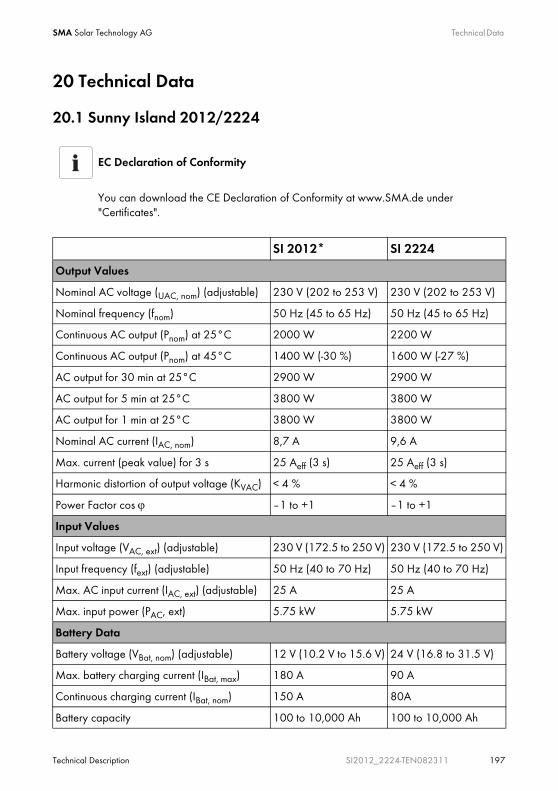
SMA Solar Technology AG Technical Data
Technical Description SI2012_2224-TEN082311 197
20 Technical Data
20.1 Sunny Island 2012/2224
EC Declaration of Conformity
You can download the CE Declaration of Conformity at www.SMA.de under "Certificates".
SI 2012* SI 2224
Output Values
Nominal AC voltage (UAC, nom) (adjustable) 230 V (202 to 253 V) 230 V (202 to 253 V)
Nominal frequency (fnom) 50 Hz (45 to 65 Hz) 50 Hz (45 to 65 Hz)
Continuous AC output (Pnom) at 25°C 2000 W 2200 W
Continuous AC output (Pnom) at 45°C 1400 W (-30 %) 1600 W (-27 %)
AC output for 30 min at 25°C 2900 W 2900 W
AC output for 5 min at 25°C 3800 W 3800 W
AC output for 1 min at 25°C 3800 W 3800 W
Nominal AC current (IAC, nom) 8,7 A 9,6 A
Max. current (peak value) for 3 s 25 Aeff (3 s) 25 Aeff (3 s)
Harmonic distortion of output voltage (KVAC) < 4 % < 4 %
Power Factor cos ϕ –1 to +1 –1 to +1
Input Values
Input voltage (VAC, ext) (adjustable) 230 V (172.5 to 250 V) 230 V (172.5 to 250 V)
Input frequency (fext) (adjustable) 50 Hz (40 to 70 Hz) 50 Hz (40 to 70 Hz)
Max. AC input current (IAC, ext) (adjustable) 25 A 25 A
Max. input power (PAC, ext) 5.75 kW 5.75 kW
Battery Data
Battery voltage (VBat, nom) (adjustable) 12 V (10.2 V to 15.6 V) 24 V (16.8 to 31.5 V)
Max. battery charging current (IBat, max) 180 A 90 A
Continuous charging current (IBat, nom) 150 A 80A
Battery capacity 100 to 10,000 Ah 100 to 10,000 Ah

Technical Data SMA Solar Technology AG
198 SI2012_2224-TEN082311 Technical Description
Charge control IUoU procedure with automatic full and equalization charge
IUoU procedure with automatic full and equalization charge
Battery type VRLA/FLA/NiCd VRLA/FLA/NiCd
Efficiency/power consumption
Max. efficiency 93.0 % 93.6 %
Operating consumption with no load (in standby)
6 W 6 W
Certification
CE CE
Protection rating
in accordance with DIN EN 60529 IP 54 IP 54
USA not available not available
Device protection
short circuit
Overload
overtemperature
Yes
Yes
Yes
Yes
Yes
Yes
Interfaces
Display:
Operating elements:
Electrically separated control contacts:
Communication:
External display:
Data storage and firmware update via SRC-1:
3-color LEDs 3-color LEDs
3 keys, 3 keys,
2 multi-function relays, 2 multi-function relays,
RS485/CAN galvanically isolated (opt.),
RS485/CAN galvanically isolated (opt.),
Sunny Remote Control 1 (SRC-1)
Sunny Remote Control 1 (SRC-1)
MMC/SD card MMC/SD card
Digital input level (Dig-In) high level starts at 6 V (up to 35 V), low level 0—2 V
high level starts at 6 V (up to 35 V), low level 0—2 V
SI 2012* SI 2224

SMA Solar Technology AG Technical Data
Technical Description SI2012_2224-TEN082311 199
Load limits for multi-function relays 1 and 2:
connection to ohmic loads
connection to strongly inductive loads
AC1: 6.0 A at 250 V~
AC15: 1.2 Aat 250 V~
AC1: 6.0 A at 250 V~
AC15: 1.2 Aat 250 V~
Interruption time
Maximal interruption time 50 ms 50 ms
Mechanical data
Width x height x depth (470 x 445 x 185) mm (470 x 445 x 185) mm
Weight approx. 18 kg approx. 18 kg
Ambient conditions
Ambient temperature from –25 °C to +60 °C from –25 °C to +60 °C
Miscellaneous
Guaranty (EU) 5 years 5 years
Accessories
External battery temperature sensor included included
Generator Manager (GenMan) optional optional
External DC fuse (BatFuse) required (not included in delivery)
required (not included in delivery)
External DC charge controllers (SIC40) optional optional
* The technical data for the SI 2012 are preliminary
SI 2012* SI 2224
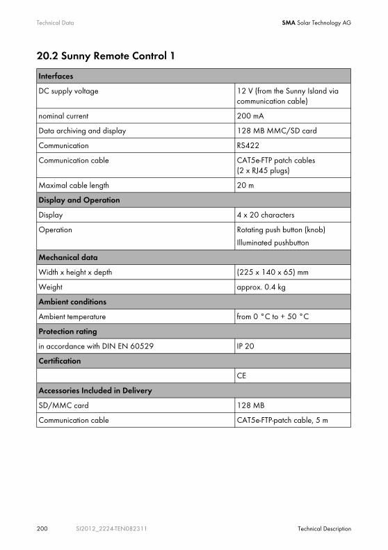
Technical Data SMA Solar Technology AG
200 SI2012_2224-TEN082311 Technical Description
20.2 Sunny Remote Control 1
Interfaces
DC supply voltage 12 V (from the Sunny Island via communication cable)
nominal current 200 mA
Data archiving and display 128 MB MMC/SD card
Communication RS422
Communication cable CAT5e-FTP patch cables (2 x RJ45 plugs)
Maximal cable length 20 m
Display and Operation
Display 4 x 20 characters
Operation Rotating push button (knob)
Illuminated pushbutton
Mechanical data
Width x height x depth (225 x 140 x 65) mm
Weight approx. 0.4 kg
Ambient conditions
Ambient temperature from 0 °C to + 50 °C
Protection rating
in accordance with DIN EN 60529 IP 20
Certification
CE
Accessories Included in Delivery
SD/MMC card 128 MB
Communication cable CAT5e-FTP-patch cable, 5 m
SMA Solar Technology AG Contact
Technical Description SI2012_2224-TEN082311 201
21 ContactIf you have technical problems with our products, contact the SMA Service Line. We require the following information in order to provide you with the necessary assistance:
• Inverter type (Sunny Island 2012/2224, see name plate)
• Type of voltage/frequency
• Serial number (see name plate or parameter "312.03 SN")
• Firmware version (see parameter "312.02 FwVer")
• Error message shown on the display
• Battery type
• Nominal battery capacity
• Nominal battery voltage
• Communication products used
• Type and size of additional energy sources (generator, PV system, Sunny Boy)
• If a generator exists:
- Generator type
- Generator capacity
- Max. generator current
- Generator interface
SMA Solar Technology AG
Sonnenallee 1
34266 Niestetal, Germany
Tel. (+49) 561 95 22 - 399
Fax:+49 (561) 95 22 - 4697
www.SMA.de
Recording of data and events.
Always use the MMC/SD card for saving data and events. This way, in case of a failure, the SMA Solar Technology AG can help you quickly.
To ensure that you have saved the present error list and event list on the MMC/SD card, write all data to the MMC/SD card with the parameter "550.03 CardFunc" and the option "ForceWrite".
Glossary SMA Solar Technology AG
202 SI2012_2224-TEN082311 Technical Description
22 GlossaryAbsorption PhaseConstant V phase: a charging phase using constant charging voltage. The charging current constantly decreases during this phase.
ACAbbreviation for "Alternating Current".
AC CouplingThe connection of various loads, generators and storage devices on the AC side.
AGM BatteryAbsorbent Glass Mat separator battery. This is a battery where the electrolyte (a mixture of water and sulfuric acid) is bound to a fiberglass mat. This is a type of so-called closed lead acid battery. A gas mixture (hydrogen and oxygen) is always generated when lead acid batteries are charged, and in normal operation this is internally recombined to form water. This removes the need for regularly refilling the battery cells with water, which is why these batteries are often described as “low maintenance” or even “maintenance free”. AGM batteries are available from many different manufacturers for a wide range of applications. They usually have very good high current properties but are not very charge-cycle resistant.
AhAbbreviation for “ampere hours”: unit of electrical charge; one ampere hour is the charge provided by a constant current of 1 A over a period of one hour - when two separate charges are connected.
Anti-IslandingAnti-Islanding is a procedure for preventing unintended islanding on the generator and/or external grid connection point. It is required in order to ensure that, in case of a public grid dropout or generator failure, the Sunny Island reliably prevents possible reverse voltages in these power supply units.
Automatic Disconnection DeviceThe “automatic disconnection device between a grid-parallel, power-generating system and the public low voltage grid” (DIN VDE 0126-1-1) is an equivalent replacement for a normal public disconnection device with isolation function which is accessible to the distribution grid operator at any time. This is a mandatory safety device which prevents energy from a solar power system being fed into an external power grid when the external power generator is not functioning. In the Sunny Boy / Sunny Mini Central, this function is performed by the "SMA grid guard Version 2". In the case of the Sunny Backup 2200 and Sunny Backup 5000 it is integrated in the Automatic Switch Box.

SMA Solar Technology AG Glossary
Technical Description SI2012_2224-TEN082311 203
Automatic Switch BoxSwitching unit which switches the Sunny Backup System between grid and off-grid operation. In grid operation, a PV plant in the Sunny Backup System is operated via an automatic disconnection device at its own feed-in counter. If the grid drops out it is switched to the stand-alone grid separated from the public grid. The box can optionally integrate a diesel generator into the Sunny Backup System.
Backup systemSo-called backup systems are power supply systems which provide an extra level of security for standard power supply systems. The public grid is usually the standard power supply system, which is backed up by an additional stand-alone grid system in case of a power outage. In addition to the backup systems, diesel generators in PV battery systems are also described as backup generators. Here they perform the same task as a backup system does for the public grid.
BatteryA battery is an electrochemical storage device which can release previously stored chemical energy as electrical energy. A distinction is made between non-rechargeable primary elements (often used in consumer markets, for example) and rechargeable secondary elements (accumulators). In so-called stand-alone grid systems, the batteries used as rechargeable secondary elements are almost exclusively lead acid batteries and, very rarely, nickel/cadmium batteries.
Battery BankSee Battery System.
Battery Charging ModeA battery inverter operating mode, in which the inverter takes energy from the AC grid to recharge the battery in a controlled fashion. In this operating mode, the battery inverter is primarily responsible for correctly charging the battery, and acts as an independent battery charger.
Battery InverterSee Battery Power Converter.
Battery ManagementThe battery management is responsible for optimal battery charging and reliable protection against deep discharge. This is the only way of ensuring that the battery service life reflects the manufacturer's specifications.
Battery Power ConverterA bidirectional power converter which can regulate voltage and frequency in a stand-alone grid and is also responsible for correct battery charging.
Battery SystemSeries connection and possibly also parallel connection of several identical batteries. Battery banks of 12 V, 24 V, 48 V and 60 V are typical.
Glossary SMA Solar Technology AG
204 SI2012_2224-TEN082311 Technical Description
Boost ChargeQuick charge: allows the battery to be charged to a level of approx. 85 – 90 % as quickly and efficiently as possible.
Bulk PhaseI-Phase: the charging phase in which charging can be performed using the maximum charging current.
CapacityDescribes the storage capability of a cell or battery, specified in Ah (ampere hours). The capacity of a battery is heavily dependent on the charging cycle, the amount of current drawn and the temperature.
Central inverterAn inverter concept in which all PV modules are connected to each other (in series and/or parallel) and which uses a single inverter for feeding energy into the external grid. The lower cost of the inverter is usually offset by the much higher installation outlay required and possible yield losses due to variations in shadowing on individual solar modules.
Charge LevelDescribes the present amount of charge which can be drawn from the battery, in percent of the nominal capacity (100 % = battery full, 0 % = battery empty).
Charge ModeSee Battery Charging Mode.
Charging ThroughputSee Nominal Charging Throughput
ClusterSeveral Sunny Island or Sunny Backup inverters which are connected in parallel on the DC side, and which are connected to a shared battery system. On the AC output side, these inverters can also be connected in parallel (single-phase system), or form a multi-phase system. The devices within a cluster must be connected via a communication cable and configured in a way that one device (−> master) leads the cluster and all other devices (−> slaves) communicate with the leading device.
C-RateThe nominal capacity specification is always provided along with the discharge time on which the capacity is based. The nominal capacity is the product of the constant charging current IN and the discharge time tN, which passes between commencement of discharging the fully charged battery and when the final discharge voltage VS is reached. For permanently on-site batteries, the C10 capacity is usually specified. I. e. a battery with C10 = 200 Ah can be discharged for 10 hours at a nominal current of 0.1 × C10 = I10 = 20 A.
DCAbbreviation for "Direct Current".

SMA Solar Technology AG Glossary
Technical Description SI2012_2224-TEN082311 205
DeratingA controlled reduction in performance, usually dependent on component temperatures. Compared with the (also common) practice of completely shutting down the device, the effect on the external grid is smaller with derating.
DSPAbbreviation for Digital Signal Processor. A DSP is a microprocessor chip especially developed for digital signal processing and control.
ElectrolyteAllows the conduction of ions within a battery.
In a lead acid battery, the electrolyte is diluted sulfuric acid and is also a reactant in the electrochemical reaction.
Nickel/cadmium batteries use an alkaline electrolyte (potassium hydroxide).
EPROMSee Flash EEPROM.
Equalize ChargeEqualization charge: allows different series-connected battery cells to be charged to a unified charge level of 95 – 100 %. Without regular equalization charging, the charge states of the individual cells slowly drift apart, which can lead to premature battery bank failure.
Equalization ChargeSee Equalize Charge.
Extension Clustersee sub-cluster
FirmwareFirmware is software which is embedded in a chip in various electronic devices, such as hard disk recorders, DVD burners and players, newer television sets, household appliances and computers - in contrast to software, which is stored on hard drives, CD-ROMs or other media. These days, firmware is usually stored in a flash memory or an EEPROM.
FLAFlooded lead acid battery: a lead acid battery with liquid electrolyte, also often described as a closed lead acid battery.
Glossary SMA Solar Technology AG
206 SI2012_2224-TEN082311 Technical Description
Flash EEPROMThe abbreviation EEPROM stands for Electrically Erasable Programmable Read-Only Memory. Flash memories are digital storage devices (chips). The exact designation is "flash EEPROM". In contrast to "normal" EEPROM memories, in flash EEPROM it is not possible to delete individual bytes (the smallest addressable memory units).
EEPROM is a non-volatile, electronic memory component used (for example) in computer technology, and mainly in embedded systems.
Flash EEPROMs are used where information must be permanently stored in the smallest amount of space, e.g. for storing the firmware.
Float ChargeAllows the battery to be slowly charged to a charge level of 100 % without the negative effects of overcharging. Complete charging to 100% using float charge takes several days. For this reason, float charging is more important for grid backup systems and less important for stand-alone grids.
Full ChargeFull charge: recharging of the battery to a level of approx. 95 % on a regular basis (at least once a month). This efficiently avoids premature battery aging caused by inadequate charging.
Full charge xxxSee Full Charge
Gel BatteryA type of battery in which the electrolyte (a mixture of water and sulfuric acid) is bound into a gel. This is a type of so-called closed lead acid battery. A gas mixture (hydrogen and oxygen) is always generated when lead acid batteries are charged, and in normal operation this is internally recombined to form water. This removes the need for regularly refilling the battery cells with water, which is why these batteries are often described as “low maintenance” or even “maintenance free” (see also AGM battery). Gel batteries are available from many different manufacturers for a wide range of applications. There are gel batteries for high-current applications but also for cycle operation with very high cycle resistance.
GeneratorAn electrical generator is an electrical machine which converts kinetic or mechanical energy into electrical energy. Here, not only the electrical generator itself, but also the combustion unit (diesel, petrol, or gas motor) necessary for the power unit is combined together with the electrical generator and simplified under the term "generator". This is also described colloquially as a power generator.
Grid-connected systemPV system which is connected to the power supply grid of an external energy supplier.
InverterA device for converting the direct current (DC) from the PV generator into alternating current (AC), which is necessary for connection of most normal household devices and especially for feeding solar energy into an existing supply grid. Inverters for PV systems usually include at least one MPP tracker, store operating data, and monitor the grid connection of the PV system (see also MSD).

SMA Solar Technology AG Glossary
Technical Description SI2012_2224-TEN082311 207
Invert ModeSee Inverter Operation.
Inverter operationOperating mode of a battery inverter where it supplies the stand-alone grid from the battery energy. In this operating mode, the battery inverter is especially responsible for the control of frequency and voltage in the stand-alone grid.
IslandingIslanding is the undesired formation of an island system on the generator and/or external grid connection point. There is a danger that, if there is a public grid outage or generator failure, the Sunny Island may deliver reverse voltages in these power supply units.
Main ClusterThe leading cluster in a multicluster system. The main cluster, for example, has the tasks of voltage and frequency regulation, grid monitoring, generator control, load management, and control of the Automatic Switch Box in a backup system.
Maintenance Chargesee Float Charge
MasterConfiguration setting that defines a Sunny Island or backup inverter to be the master within a cluster. This stipulates that centralized control and monitoring tasks, which in a cluster must be performed by just one device (e.g.,frequency regulation, battery management, generator control, and control of the Automatic Switch Box in the Sunny Backup system) are to be performed by this device. All other inverters of the cluster must be configured so as to leave these tasks to the master, and to be led by the master (−> Slave). The master is also the device at which the cluster's configuration, operation, and data recording occurs in a centralized manner.
Maximum Power Point "MPP"The working point (current/voltage characteristic curve) of a PV generator where the maximum power can be drawn. The actual MMP changes constantly depending on, for example, the level of solar irradiation and the ambient temperature.
MPP trackerRegulation of the power drawn so that a PV generator is operated for as long as possible at the MPP. This operating point varies with the solar irradiation and temperature conditions of the modules. MPP tracking optimizes the extraction of electrical power and is a feature of inverters and charge controllers.
MSDSee Automatic Disconnection Device.
Glossary SMA Solar Technology AG
208 SI2012_2224-TEN082311 Technical Description
Multicluster SystemParallel connection of several clusters on the AC output side in a stand-alone grid or backup system. The master devices of the individual clusters must be connected by communication cables, and configured in such a manner that one cluster leads the entire system (see main cluster) and the master devices of all other clusters (see sub-cluster) communicate with the master of the main cluster.
Multi-string inverterAn inverter which to a great extent combines the advantages of several string inverters (separate MPP tracking of individual strings) and a central inverter (low performance-specific costs).
NiCdNickel/cadmium battery, contains nickel, cadmium, and potassium hydroxide as the electrolyte. These require a significantly higher charging voltage, have a lower level of efficiency and are significantly more expensive than lead acid batteries. However, their robustness, cycle resistance and low-temperature capabilities mean that they are used in certain special applications.
NLMAbbreviation for "Netzleitungsmodem" (Powerline modem): communication between SMA inverters and monitoring devices is possible via a cable, a radio link, or a Powerline modem. Powerline modems use a carrier frequency of approx. 132 kHz modulated onto the AC cables, and data is transferred using FSK (Frequency Shift Keying) of this carrier signal. Details on the Powerline modem can be found in the technical description of the SMA-NLM among other places.
Nominal Charge ThroughputThe charging throughput is the cumulative total discharge current over time, measured in ampere hours (Ah). These meters are not automatically reset after charging. The nominal charging throughput is the charging throughput with regard to the nominal capacity of the batteries.
Overload CapabilityThe overload capability of an inverter describes its ability to supply short-term (seconds or minutes) excessive loads that can be significantly higher than the nominal capacity of battery inverters. The overload capability is important to allow startup of electrical machines which have a nominal power output close to the nominal power output of the stand-alone grid inverter, since these machines typically require six times the nominal current when starting.
Parallel connectionParallel connection of batteries (all positive poles together and all negative poles together) increases the capacity of the battery bank while keeping the voltage constant. For example, two 24V/100Ah batteries connected in parallel still have a voltage of 24 V, but have a capacity of 100 Ah + 100 Ah = 200 Ah.
PhotovoltaicsSee "PV"

SMA Solar Technology AG Glossary
Technical Description SI2012_2224-TEN082311 209
Piggy-Back (Board)A printed circuit board which is plugged into another board to increase performance or expand capabilities. A piggy-back board can also replace an individual chip. In this case, the chip is removed and the board is plugged into the empty socket.
PLCAbbreviation for "power line communication": describes the process of data transfer over the grid connection. The PLC power module is used to amplify the signal and is connected in Multi-String and Sunny Mini Central inverters.
PVPhotovoltaics (PV) is the conversion of solar irradiation into electrical energy using special semiconductors, so-called solar cells.
PV-generatorTechnical device for the conversion of light energy into electrical energy. This term encompasses all the electrically connected (in series and in parallel) solar modules in a PV system.
PV-moduleSee "Solar module".
PV systemDescribes a solar power system for generating electrical power. This includes the complete collection of components required for the acquisition and utilization of solar energy. As well as the PV generator, this also includes the Sunny Boy or Sunny Mini Central inverter, for example, in the case of grid-connected systems.
Rapid Chargesee Boost Charge
Self DischargeCapacity loss of a battery cell while it is stored or not used. A higher ambient temperature has a strong influence on self discharge.
Series ConnectionIn this case the positive pole of each battery is connected to the negative pole of the next battery. There is only one circuit where current can flow. Series connection increases the voltage of the entire battery bank. If two 24 V batteries with a capacity of 100 Ah each are connected in series, the total voltage is 24 V + 24 V = 48 V, while the total capacity remains at 100 Ah.
SlaveA configuration setting which assigns a subordinate role in a cluster to a Sunny Island or Sunny Backup inverter. Thus, this device is relieved of control tasks and monitoring tasks, which must (or may) only be performed by one device in a cluster (−> master). Slave devices accept the configuration settings, present firmware, and start/stop commands from the master, and report these events, as well as warnings and error messages.

Glossary SMA Solar Technology AG
210 SI2012_2224-TEN082311 Technical Description
SOCState of Charge: the charge level of the battery, see Charge Level. If, for example, 25 Ah is taken from a 100-Ah battery, the charge level (SOC) is then 75 %.
SOHState of health: describes the relationship between the present capacity and the battery's nominal value, given as a percentage.
Solar cellAn electronic component which generates electrical energy when irradiated with sunlight. Since the voltage produced by a single solar cell is very small (approx. 0.5 V), several solar cells are combined to form a solar module. The most common semiconductor material presently used for solar cells is silicon, which is manufactured in different forms (monocrystalline, polycrystalline, amorphous). In addition to vastly different mechanical variations, which are usually designed to increase the level of efficiency, completely new materials are currently being tested (cadmium telluride, cadmium indium sulphide, titanium dioxide and many others).
Solar energy"Sun energy", this means energy from sunlight or other solar irradiation (heat and/or UV radiation).
Solar moduleElectrical connection of several solar cells encapsulated in a housing to protect the sensitive cells from mechanical stress and environmental influences.
Stand-alone grid systemAn energy generation system which is completely independent of any external power sources.
StringDescribes a group of solar modules electrically connected in series. A PV system usually consists of a number of strings, which avoids excessive yield losses caused by variations in shadowing on different modules.
String inverterAn inverter concept which avoids the disadvantages of the central inverter concept. The PV generator is split into individual strings, each of which is connected to the external grid by means of its own string inverter. This greatly simplifies installation and reduces the yield losses which can be caused by manufacturing deviations or variations in shadowing on the solar modules.
Sub-Cluster (Extension Cluster)Cluster in a multicluster system which is subordinate to the main cluster and is therefore not responsible for the management of the entire system.
VRLAValve regulated lead acid battery: lead acid battery with semi-solid electrolyte or closed lead acid battery. Examples of this type of battery are gel batteries and AGM batteries (Absorbent Glass Mat).

SMA Solar Technology AG Legal Restrictions
Technical Description SI2012_2224-TEN082311 211
The information contained in this document is the property of SMA Solar Technology AG. Publishing its content, either partially or in full, requires the written permission of SMA Solar Technology AG. Any internal company copying of the document for the purposes of evaluating the product or its correct implementation is allowed and does not require permission.
Exclusion of liabilityThe general terms and conditions of delivery of SMA Solar Technology AG shall apply.
The content of these documents is continually checked and amended, where necessary. However, discrepancies cannot be excluded. No guarantee is made for the completeness of these documents. The latest version is available online at www.SMA.de or from the usual sales channels.
Guarantee or liability claims for damages of any kind are excluded if they are caused by one or more of the following:
• Damages during transportation
• Improper or inappropriate use of the product
• Operating the product in an unintended environment
• Operating the product whilst ignoring relevant, statutory safety regulations in the deployment location
• Ignoring safety warnings and instructions contained in all documents relevant to the product
• Operating the product under incorrect safety or protection conditions
• Altering the product or supplied software without authority
• The product malfunctions due to operating attached or neighboring devices beyond statutory limit values
• In case of unforeseen calamity or force majeure
The use of supplied software produced by SMA Solar Technology AG is subject to the following conditions:
• SMA Solar Technology AG rejects any liability for direct or indirect damages arising from the use of software developed by SMA Solar Technology AG. This also applies to the provision or non-provision of support activities.
• Supplied software not developed by SMA Solar Technology AG is subject to the respective licensing and liability agreements of the manufacturer.
SMA Factory WarrantyThe current guarantee conditions come enclosed with your device. These are also available online at www.SMA.de and can be downloaded or are available on paper from the usual sales channels if required.
TrademarksAll trademarks are recognized even if these are not marked separately. Missing designations do not mean that a product or brand is not a registered trademark.
SMA Solar Technology AG
Sonnenallee 1
34266 Niestetal
Germany
Tel. +49 561 9522-0
Fax +49 561 9522-100
www.SMA.de
E-Mail: [email protected]
© 2004 to 2008 SMA Solar Technology AG. All rights reserved

SMA Solar Technology AG
www.SMA.deSonnenallee 1
34266 Niestetal, Germany
Tel.: +49 561 9522 4000
Fax: +49 561 9522 4040
E-Mail: [email protected]
Freecall: 0800 SUNNYBOY
Freecall: 0800 78669269