OBJECT of speed of testing upon the stress-strain relation.
30
Transcript of OBJECT of speed of testing upon the stress-strain relation.


REPORT NO. /O ̂ £/ DISTRIBUTION OF REPORTS
DATE DISTRIBUTED. ~4lit!JL NO. OF COPIES. ÄS. -.!
:> / Author
Üb. File _ /
Main Offic« File
Chief of Ordnance ~ I j
Springfield Armory
Hatervliet Arsenal w/
Rock Island Arsenal - '
Frankford Arsenal
Picatinny Arsenal
Aberdeen Proving Around
Extra Copies /
Other establishments requesting work.
i _
/,
-I
/*>.
/
771 - /
1 ^ ] •' r i : r,
u U.fates'i/^/'/ 3
'//.,
DISTRIBUTIOirSJl
tefOf«! for pobUe
/-
i*?,'rSfel
— ^-~. -• a.-^:-*:«.i^Ti 1 mi" --

Report V.o. 112/25 Watertown Arsenal Sx 0. 5S
Jvdy 15, I9I+2
HIGH SPESD TESTINa
A Crltltiue of the Measurements of the Stress-Strain Relation
at High Speeds
OBJECT
To interpret the results of previous erperinents on the Effect
of speed of testing upon the stress-strain relation.
Eg^RENCE
The references to this report are submitted ao Anpendix B.
CCIICLUSICNS
1. The stress variation in a tensile specimen "being tested at velocities
higher than 100 fps io so great that the neasured streos-strain curve, or any
qunntitlec derived therefron, have little or no significance. (Tig. l)
2. Valuable information regarding the relation between stress and strain
at high rates of deformation nny be obtained by extrapolating the results ob-
tained from lower rates by standard testing machines. (Fig. 6)
3. In all materials the strain-hardening curve rises with increasing
rates of deformation. (Fig. 2)
U. In mnny cteels, perhaps in all, the yield stress io equal to the ten-
sile stress at rates of strain applicable to ordnance problems. {Fig. 6)
6. The equality of the yield and tensile strength at high rates of def-
. ormation is responsible for the shear type of failure peculiar to high rates
of strain. «
7. The upper yield point is so sensitive to the surface finish, the shape
HNMHt&Mälai*'
s*«r:l

*m
of the specimen, and its eccentricity in loading, that its neasurenent gives
little indication as to how the naterial will "behave under service conditions.
/ John H. KolloDon / y2nd Lt., Ordnance Dept.
C. Zenor Physicist
APPROVED:
Coloi^l, Ordnpdice Dept. Director of Laboratory
\
Aoeession For KTIS GRA&I DTIC TAB Unannounced rustificatlpi
¥ UJA.
By Distribution/
Availability Codes^ Avail and/or
Spaoial
UNANNOUNCED
-2-
"MMMWMrtHHNWMB ■■•
SBSHP*?^1^-*'"" ^HIIWP»':^^^ «pyg «illprW ,

^
"Ihe off-cannce that a future ^enoratlon mny discover a slgnlfledmce
in our utterryices is scarcely an excuse for nnlcinc meanlngloos nolseo."
—Eddington
I ^^
. »»«»HissKj^wtfÄiiaÄii. ■
'■'^^«t; ■<.'5gPHS<!«|Se^5»?'' . -.jjKwr !^i»* -im^m wmm.

IHTROIOCTIOy
OrdnnDce materiel Is ou"bJected often in service to inpulsive loads.
The response of the material may ho more readily calculated, the more is
known regarding the relation hetween stress and strain at high rates of
deformation. Such calculations will permit a more judicious choice of ma-
terial for any particular ordnance .^pplication.
In certain of these applications, it is only necessary that the ma-
terial have a sufficiently high yield strength. In other cases the
shape of the stress-strain curve is of paramount importance, for it de-
termines the speed of propagation of the elastic or plastic deformation.
Lacking this basic irJ'ormation upon tho stress-strain relations at high
rate of deformation, the Ordnance Department has "based acceptance speci-
fications, either upon the quasi-static properties obtained hy the usual
testing machines, or upon performance tests. The first procedure nny
lead to a poor selection of material for service conditions, while the
second procedure is costly. Since, during armor penetration, the rate
of deformation is extremely high, tho quasi-static properties are of lit-
tle significance. In order to understand the nechanian by which armor
penetration occurs, it is of primary inportrnce to determine tho effect
of speed upon the stress-strain relations of the material used for armor.
As if in response to the needs of the Ordnance Department, severA.
laboratories have recently undertaken high speed testing. In their pre-
occupation with the experimental difficulties of such testing, those lab-
oratories have neglected to analyze carefully the theory of their experi-
ments. In this paper a theoretical rnalysis of the tensile test at high
speeds is presented. This analysis indicates that measurements made at
high speeds (above lOOl^s) cannot give load-elongation curves nor nny
-3-
■<■■ imr mtmaumifmm&a: , „, »^ ■■ *—■"an-on- ■ »«•«• ■ *
'■«•■vl • •■vfi't**""»'»!»*- >»"S. ffi '
qunntitles derivr'.'ble therefron, such t>.B jner^y of rupture. Useful Infor-
nr.tion relntivs to high rates of deformtion can "be obtoined, however,
with the usual types of testing r.p.chlnes "by extrapolating the reeults to
higher rates of strain. An exanination was nade of the literature on
the effect of speed in this lower range, nnd the results are presented in
this report.
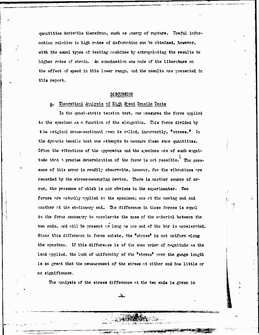
DISCUSSION
a. Theoretical Ar-alyais of Hi^i Sbeed Tensile Tests
In the quasi-static tension test, one neasures the force applied
to the specinen as a function of the elongation. This force divided by
the original cross-sectional area is oallsd, incorrectly, "stress." In
the dyroriic tensile test one attempts to neaoure these sar.o quantities.
Often the vibrations of the apparatus and the specimen are of such m-Tgni- 1
tude that a precise determination of the force is not posoihlo. The pres-
ence of this error is readily observable, however, for the vibrations are
recorded by the stress-measuring device. There is another source of er-
ror, the presence of which is not obvious to the experimenter. Two
forces are actually applied to the specimen; one at the moving end nnd
another at the stationary end. The difference in those forces is equal
to the force necessary to accelerate the mass of the material between the ■
two ends, and will be present an long as one end of the bar is accelerated.
Since this differor.co In force exists, the "atress" is not uniform along
the specimen. If this difference is of the same order of magnitude as the
load applied, the lack of uniformity of the "stress" over the gunge length
is so great that the measurement of the stress at either end has little or
no significance.
The analysis of the stress difference at the two ends is given in
»^-^»»»VJKü^S**^:^.
■ • :i'5V>>jlfl*« l¥J*-~- H* - ' «JWJH^^WMM»*^
'■-■■■

Appendix A. Pig. 1 illustrates this stress difference in the particular
case wher» tne velocity of the head of the machine increases linearly with
time, until a strain of 0.1 is reached. If the final velocity is reached
at a smaller strain, the stress difference will of course he greater.
The results indicate that in testing steels at velocities greater than 100 fps,
the error introduced in this manner nay "be a large percentage of the measured
"stress."
The rate of strain nay he increased by decreasing the ^jß^e length as
well as "by increasing the speed of testing. Decreasing the giyfee length,
however, increases the possibility of stress concentrations, increases the
uncertainty of the extrapolation to larger sizes, and increases the experi-
mental difficulties. In order to obtain results applicable to material de-
formed at high speeds, it if. advisable and perhaps necessary to extrapolate
from lower strain rates.
b. Interpretation of the Literature
In one respect all metals reoct similarly to an increase in test-
ing speed; the stress-strain curve in the plastic region is raised as the
speed is increased and the magnitude of the rise increases with increasing
stress. (Pig. 2) Iron and steels/ yhich e:diibit a drop in load at the
yield pointy behave in a characteristic manner. The yield point (lower) 3-11
increases with increasing rate of strain faster tlmn the tensile strength.
This behavior is illustrated by data obtained by Winloch and Leiter5 and
presented in Pig. 3» ^e data presented in this figure were obtained from a
steel containing .055» carbon, annealed, and having a grain count of 90 per
square inch at 100 nr^ni float ion. (A. S. T. M. Ho. 7)
The lower yield point is used as the criterion for the beginning of
plastic deformation, rather than the upper yield point, since the latter
is dependent upon the stirface condition, ruid ^hape of the specimen, nnd
upon any slight eccentricity in loading. The lower yield point appears to '^ -5-
, ■■mm » •- ■'>~^. « we .vasr»»^»*- .-S| -•■•■■ «--«»^ '

characteristic of the metal itself. Experiments have heen performed in
which the upper yield point was raised as high as. or higher thin, tho
tensile strength, even in quasi-static tests. The effect of speed on ma-
terials with upper nnd lower yield is presented schematically in Pig, U.
The stress-strain relation for such materials can be considered as made up
of two curves essentially independent of rate of strain joined "by horizon-
trd lines. The first part of the tot al stress-strain curve is elastic;,
in the second p^rt, inhomogeneous defonnatlon occurs; *ind in the third part,
the material undergoes homogeneous deformation accompanied hy work harden-
ing and sensible reduction of area. In this flfuro the slight effect of
speed beyond the lower yield point is neglected. As the speed is increased,
the horizontal portion of the stress-strain curve rises, and the amount of
strain at this lower yield point increases.
Daring the second part of the deformation, the strain occurs by the
formation and spreading of luder bonds* In each Luder band the strain is
equal to the yield point elongation. Only after all of the specimen has
been traversed by Lüder bands does it deform homogeneously. IVom Tig« U
it appears that a critical strain ^exists, above which the specimen will
fail by shear along the first and only Luder b.-yid formed, nnd homogeneous
deformation will not occur. The usefulness of the schematic diagram in
fig. U for tension suggests that a similar one be constructed for pure
shear. Such a diagram is presented as 7ig. 3. This dingrnm illustrates
the approximate behavior in shear of the sane steel to which Pig. U per-
tains. Since in pure shear, the static strsss-stralb curve does not pass
through a naximun as does the force-elongation curve for tension, a criti-
cal rate of shear beyond which all deformation is confined to a single b«nd
does not necessarily exist. The yield point elongation, and hence the
elongation associated with each Lüder band, increase rapidly with increas-
ing rate of strain. When, however, this yield point elongation is so
-6-
"WBS^iA^^ -.i*-
■ ^ -^'..-^--^WW ■«***•»"■■, --**£"'
- m ,.>

Iftrfje tlrit the tenperature rloo ?f the nnterinl in the hnnd Is several
hundred decrees centigrade, the "Btatic" atreso-striin ciarve will "be low-
ered. In this cp.se the deformtion to fracture nny llkewiee he confined
to .1 narrow hand.
in indirect ßubstnntintion of this conclusion cay he found in the lU
work of Itihara. Ho found that hy raising the rate of stralji hy a factor k
of U x 10 over that in the quasi-static tests, the yield point was dou-
hled, while the naxinun stress renained essentially unchanged. The details
of the stress-strain curve were «hscured, however, by vibrations. The
curves in Pics. 3i ^* nnd 5 refer specifically to a single type of steel 3
tested hy Winlock nnd Leiter. The general features of these curves will
apply to any steel with a lower yield point. In particular the lower yield
stress approaches the tensile strength at high rates of deformation. In an
attenpt to find those factors which influence the rise of the lower yield
point with rote of strain nn extensive search was nade in the literature of
the effect of speed on the tensile teat. Kost of the investigators recorded
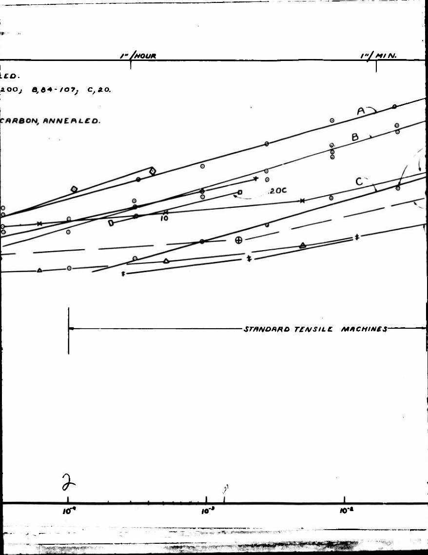
only the upper yield point. Fig. 6 shows all the da^ in which the lower
yield strengths, as well as the tensile strengths, were reported as a func-
tions of the rate of strain.
In all cases the ratio (lower yield stress/tensile strength) approaches
an asynptote at low rates of strain, and varies nearly logarithnically at
higher rates of strain. The ratio is dependent upon the carbon content,
decreasing as the carbon content increases. For a given carbon content the
ratio is larger, the smaller the grain size. The absolute magnitude of the
ratio as well as its dependence upon rate of strain should be dependent
upon the micro structure, as well as upon carbon content, but a detailed
study of the effect of these variables i« lacking. The values of this
ratio obtained from the tensile impact machine are consistent with the
extrapolation of the data obtained from the standard testing machines, -7-
9. 10
matmci*&am»ä&iitei&&*^-' ^,,*-j5-*.f-'«aiai;-3w.,;4f-'. ,..•#■■
'»*%■'■" ;■•■ ' "-■" —---w mm

-1 Although the unit of rate of strain used In fig. 6, nnmely sec Is
the most logical unit, it is one for which few hnye any physical grasp.
In order to give the rates more concrete expression, nn interpretation of
these units is presented along the top margin in terms of the rate at vhich
the head of a one-inch gauge length specimen must move to produce the ap-
propriate rn,te of strain.
£. Application to Ordnance Materiel
The relevance of high speed tests to ordnnnoe prohlems crji hest
he seen "by indicating in Fig. 6 the ringe of strain rate associated with
each type of test, together with the range of strain rat« nssociated with
each typ«? of ordnance problem. The order of nngnitude of the rate of strain
at which the material of the breech of a gun is deformed during firing is
obtained by dividing the maximum elastic strain of n.bout .002 by the time
interval of .001 sees. This rate of strain lies considerably below that in
impact testing, considerably abo*e that obtained in standard tests, nnd is
the middle of the range of strain rates at which the lower yield stress be-
comes equal to the tensile ntrongth.
The raising of the lower yield stress at high r^tes of strain may have
Important iaplications. The yield strength ^t these high rates of strain
may best be determined by measuring the tensile strength at the rate of
strain obtained by the usual testing methods. In particular, if the ma-
terial in a gun barrel behaves as the material in Pig. 3i ^« yield stress
under firing conditions is nt least as large as the tennlle strength as
measured in standard nachines.
The order of magnitude of tho rate of strain of an armor plate during
penetration is given by the reciprocal of the time required for a projectile
to traverse the distance of one1 calibre. This mte varies from a minimum
3 . & of about 10 for l2"-proJectileB to a snaxinum of about 10- for calibre .30
bullets. The lower end of this range envelops the strain rates obtained
in plugging experiments with velocities in the neighborhood of 10 fps. This
*&; ^ •i^*^-SM«*»Ä<ÄÄiÄ¥4iJ.«<-a™'""
''Trrrvn' ■-•^^
■ - ■ -
lW* "■»-» ' » B*Mf
overl.-'.ppinc BU^ests the relevnnce of observp.tiono upon pltig^inß to the
prohlen of nmor penetration. A report upon this subject is heinc pre-
pared. An extrnpol'vtion of the curves in Fi-. 6 to the rn.te of striin per-
tenent to arnor penetration su^nssts th^t steels with as mu%h ns .5856 crr-
bon and of viryin,T nicrostructvre will behave quite difforer.tly fron low
carton steels. It is possibla that the yield strength in .5*$ carton steels
will he helow the tensile strength, vhile in .20^ crhon steels the stress-
strain curve will he flat for hl^h strain rates.
The existence of such lar^e yield point strains in shear is '>f par-
ticular significance in nmor penetration. In certain types of penetra-
tion the projectile pushes out a plu«. The defornation of the plate la
confined to the innedinte vicinity of the nearly cylindrical surface of
the plur;. In this region the plate 1)0001168 very hot, certainly ahoVe the
trnnsfomation tenpem.ture of the steel. This concentration of strain low-
ers the r>hillty of the plate to resist penetration. Since the increase of
the yield to tensile ratio with rate of strain is affected "by enrhon con-
tent and nicrostructure, the resistance to pluofjlnj "by different steels
nay be vried over a vide ranje.
■
F
-9-
]. SliiliSI! ' rf-J&^J^^^^an-T.. -.«
•■■■■' ■ ■ ■ ' "^•^^ -«»^ -4<me***vmr+

APPSKBIX jL
In this nppendiz the cnlcul*.tion is carried out for the difference
In stress nt the two ends of n. tensile specimen during n. hi^h speed test.
The difference between the forces acting nt the two ends is equnl
to the sun of the products of all the elements of nass in the ^au^o length
and their respective rccelerations.
Af-Ega^ (1)
During the entire test the ri,7ht r.en'ber of Eq. (l) is given very nearly
"by the relation
iK^^V-AAa (2) v/here^ , A and JC refer to the original density, cross-soctlonal area, and
gauge length, respectively, ind whore a refer» to the accelerations of
the uoving end. Thus, hefore nedcing, the ^cceler-^ti'-n vrrles linearly
along the specinen fron 0 to a. Here the r.ean acceleration is |a
After the onset of necking, half the specinen has practically no accelera-
tion,« the other half has nearly the acceleration a, Ag^in the nean ac-
celeration is given nearly by ^a.
After substituting Sq. (2) into Eq. (l), and dividing the resulting
equation by A, one obtains for the stress difference
AS = ^a (3)
If it is assumed th?>t the noving end of the specimen Jms acquired
the velocity v by the tine the specinen has elongated a distance J£\J(,
then the naximun value of AS during this elongation will be a ninimun if it
is a constant. This constant is given in terns of v and by the equation.
a = y2/2lJl (10
The substitution of the relation into Iq. (3) gives the fin"! equ-'tion
AS-l/U (jy^/.v2 (5)
-10-
K
5R53 ;>. :.«:*3wBP
mtmwm''wimui*££ii^ai'*i*i-
•■■-niimiWii^Mi
In the nbove equ/itioa, all quantities nuat, of course, 'be expressed
In n consistent set of units. The correspondlnt; equation for Iron or
steel In which S Is e:q?rossed In units of psl, pnd ▼ In units of
ft/sec,
/ S = 0.027 ( y /^j?) v2 In psl (^)
This equation Is pJfritted In Pi,:. 1 for the typical enso off J^= 0.1.
V'
~ll-
'"'^fVi. *1*&K^Stll'Ltof*Jty&'r '«'PftTl-lg P»'«'»^«■•,«^i,•■^

APPEmX B
•1 •
1. 2.
I: 5. 6. 7. 8.
9- 10. n. 12.
References
Nadai: Jour. Appl. Mech., June, I9U1 For a bibliography of effect of spppd, see
a. Carpenter njid Robinson: "MAtnjI' (Oxfords 1939'1 Vol. I, Pnrt I, Ch. IV
b. C. P. ^lan: Proc. Hoy. Soc. A l6£, 56g (193g) c. C. W. KacGregor: A.S.M.S, £[, A. F. H. 1S7 (1939)
J. Winlock and S. Leiter: Trans. A. S. M. 2£, 163 (I937) H. Cluinney: The Snsineer, l^J, 332 (193U) H. F. Moore and P. 0. Jones: Proc. A.S.T.M. Uo, 6l0 (19U0) E. A. Dnvis: Jour. Appl. M-sch. ^ A-137 (l33gT^ J. L. M. Korrlson: The Sngineer, l^S, lg3 (I93U) 3. Siebel and A. Ponp: Kitt aus den K. W. Inst, fur Sieenforschung
10. 63 (1939) D. S. Clark and G. Dfitwyler: A.S.T.K. ^g, 98 (193g) D. V. Ginns: Jour. Inat. Metals, 6l, 6l (1937) Korber and Storp: Mitt Z. W. Inat. Sisenforsohung J« *& (1925) J. G. Docherty and F. W. Thorne: Engineering n2. 295 (1931) C. W. McGregor: A. S. K. Z. ^ A. P. H. g 7 U93l) M. Itihara: Technology RTJB. of the Tohoku Iinl»rial University
n. 16,512 (1933); 12, 63 (1936) (-*•
■*-*
'■■*?'*?>s*>*n!$f?-

FINßL VELOCITY MfiCHINC HEfiO inJSEC)
...
~~i. y.'yfvs.fm**!*.' ■ ■*0m*~ ■>•■* ■■ riyi^'fwir'i " ": - . .

■;-, *i « ■^:^.'
K
«0
«0
*o
g 30
&o
/o
off ̂ ^
EFFECA
UPON
OF
TRUk
CUI
(lfiFT£R\
.09 ./o .15 STRAIN

.' ■"■ ■■■.■ -'--' $*m&&--
FIG. a.
EFFZCt OF RHTL OF
UPON TRUE: STRESS -
CURVE IN METALS
S TRfM N
5TRRIN
(kFT£* SI£B£L w\ POMP**
fc
.15 STRAIN
.ao .a.5
^-r^r.,r.
^ - -"W!!- • ■ ■-5.-a«|j!p j, m

/
*f
so
10
*5
e o
20
10
/0
rs
<
0
~Y.PL
(fir}
/o RHTC or srfffHN (sec.-4)
—WWW*1 -~-^- '>"«' i>a«k|aii»>,'^j||« ..:,4^^J ., V

ü
■-.•5?

—,■«««■.--^
-I <. ^fS I !
SO
90
JO
«0
o o o
w ao
ec 2? 0.3
7X/0-* ^^
JK/O'* y
FIG. <*
ax/o-' y^
Jx/o* y^
px/o-^ /
JX/O' / /XIO" / 3XJ0-* /
i 1 CURVE,
10
I
I
SCH£M/ir/C DmGRAM
LFFZCT OF SPEED UP\
TENSILE PROPERTIEX
ID RTF* FROH FIGURE J
.05 .to STRRIN
--*.,.■
•g^npii«"1--»'«»•- ■«

Al
FIG. t
SCHEMATiC DlftGRfiM OF
ZrFZCr OF 3F££0 UPON
TENSILE: PROPERTIES
iDRTR FROM FIGURE J)
.10 .15 STRHIN
■ ^öjggjayg3^55*,e»''
^
.2 0
* ■'' - - ■
1%
'z&sfvmgß

i:
O 0 0
«0
«0 FIC. 5
SCHEMATIC DIAGRAM • OF
EFFECT OF SPEED
UPON SHEAR PRCFERT/e*
mm -—"• «MM
•- rfflc
A? STRAIN
.40

,r*'i$$£&*' '"'■
k
o
Q ■o
RXTt OF STHAIN {IN StC. ')
.40
%
.60 90
=ife MMMI*^1 <
-•■■■■yf^mt^ r?

i
^
■r
tiiTWnip

AO
w k
(g -^ «I x
»^ .7 0 k 0 >i VI .< N
s. 0
^ lm/MOAirH
^
fMee* i*/Ofl Y f T—r O yNINLOCH AND LEITCR : 0.04-0.06? CAft&OA/, »NNEftLCD
NO, OF GRAINS MR SdUHRe. INCH AT /00 DIRMtrCRS I *, AOO
+t&QUIMHEy4\+J YORSHtRE. IRON RNNCRLEDj QO-tS? CRR
.3
.1
If
O MOORE s. R. a. /OJLO
<S>£>RyiS*: MILD STCCL, NORMRLISEO.
^A MORRISON i Hj O.IS'/Cj A, O.SÖl C.
♦ SIEBCL. RND ROMP: SOFT IRON
V CLRRK RND DRTWYLCR : 0./5-0./«TC /AON
'•. _ Q G / ^^J : 0./5T c '*ON
Iff*
* • ~ •■ I. ■ - -j ffinV i —
■'^Wfi^v. ^^^5'i^p^W'' »•- ^r ■»*r*»^-w«rJ,-< ' ■
f~/t 'HOUR I"/ Ml N.
AOOJ a,t*-IO7J C,äO.
Sr/WOHRD TENS ILL AAACHIN£5-
^
I ill 16* 10' io-
"••■^«fj ■■■ ■ -; •
'■ ■■' ^^1 '■ «—■■^ ■■•■■■■«.■ ■ . M->
.^P#^V!».'" **• («iP^'•««»••- ^-MW*^i J

) ■■■ %
$
6f>€£D OF M£AO FOR ONE INCH GUß
./5C
.5ÖC
GUN'S ■rCNS/Li
5 2V
FIGURL 6
EFFECT OF SPEED ON
RELATION BETWEEN
YJELD POINT AND
TENSILE STRENGTH
a/ »•««...M ■ mriTi nmi ■ m
—K y ■ ~Sr* ^- M(k Jg»» .»af - <MpJ! .. 'f/ '
?» *.-••
■

WAG£ LENGTH fO*/3e c.
■9- ■ I5C
f too'Js&e. tooo'/ste.
?c
?/2.^ IMPACT •
*LUGQINQ H StRMO* P£NE TRATK
H
i* /«* ivr

k /ooo'/s£e. r
UGCINO H -fiRMOR P£NE TRATION
1.0
Ö
.7
.5
.4
.3
.1
. ■■ t , ■ •
10*
':..,jmm*'' Y* '^ .*«*««»■<<•■•-■*( ■■