STRAIN ENERGY – Impact Loading - Memorial University …katna/5931/STRAIN...
12
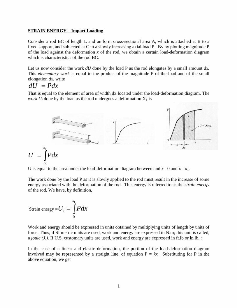
1 STRAIN ENERGY – Impact Loading Consider a rod BC of length L and uniform cross-sectional area A, which is attached at B to a fixed support, and subjected at C to a slowly increasing axial load P. By by plotting magnitude P of the load against the deformation x of the rod, we obtain a certain load-deformation diagram which is characteristics of the rod BC. Let us now consider the work dU done by the load P as the rod elongates by a small amount dx. This elementary work is equal to the product of the magnitude P of the load and of the small elongation dx. write dU Pdx = That is equal to the element of area of width dx located under the load-deformation diagram. The work U i done by the load as the rod undergoes a deformation X 1 is 1 0 x U Pdx = ∫ U is equal to the area under the load-deformation diagram between and x =0 and x= x 1 . The work done by the load P as it is slowly applied to the rod must result in the increase of some energy associated with the deformation of the rod. This energy is referred to as the strain energy of the rod. We have, by definition, Strain energy = 1 0 x i U Pdx = ∫ Work and energy should be expressed in units obtained by multiplying units of length by units of force. Thus, if SI metric units are used, work and energy are expressed in N.m; this unit is called, a joule (J.). If U.S. customary units are used, work and energy are expressed in ft.lb or in.lb. : In the case of a linear and elastic deformation, the portion of the load-deformation diagram involved may be represented by a straight line, of equation P = kx . Substituting for P in the above equation, we get
Transcript of STRAIN ENERGY – Impact Loading - Memorial University …katna/5931/STRAIN...
1
STRAIN ENERGY – Impact Loading Consider a rod BC of length L and uniform cross-sectional area A, which is attached at B to a fixed support, and subjected at C to a slowly increasing axial load P. By by plotting magnitude P of the load against the deformation x of the rod, we obtain a certain load-deformation diagram which is characteristics of the rod BC. Let us now consider the work dU done by the load P as the rod elongates by a small amount dx. This elementary work is equal to the product of the magnitude P of the load and of the small elongation dx. write dU Pdx= That is equal to the element of area of width dx located under the load-deformation diagram. The work Ui done by the load as the rod undergoes a deformation X1 is
1
0
x
U Pdx= ∫
U is equal to the area under the load-deformation diagram between and x =0 and x= x1. The work done by the load P as it is slowly applied to the rod must result in the increase of some energy associated with the deformation of the rod. This energy is referred to as the strain energy of the rod. We have, by definition,
Strain energy =1
0
x
iU Pdx= ∫
Work and energy should be expressed in units obtained by multiplying units of length by units of force. Thus, if SI metric units are used, work and energy are expressed in N.m; this unit is called, a joule (J.). If U.S. customary units are used, work and energy are expressed in ft.lb or in.lb. : In the case of a linear and elastic deformation, the portion of the load-deformation diagram involved may be represented by a straight line, of equation P = kx . Substituting for P in the above equation, we get
2
121 1 1
0
1 12 2
x
iU kxdx kx Px= = =∫
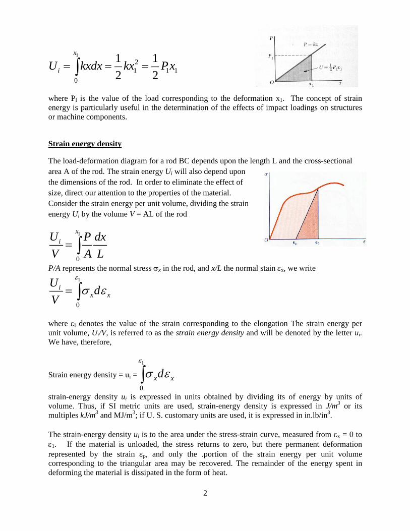
where Pl is the value of the load corresponding to the deformation x1. The concept of strain energy is particularly useful in the determination of the effects of impact loadings on structures or machine components.
Strain energy density
The load-deformation diagram for a rod BC depends upon the length L and the cross-sectional area A of the rod. The strain energy Ui will also depend upon the dimensions of the rod. In order to eliminate the effect of size, direct our attention to the properties of the material. Consider the strain energy per unit volume, dividing the strain energy Ui by the volume V = AL of the rod
1
0
xiU P dx
V A L= ∫
P/A represents the normal stress σx in the rod, and x/L the normal stain εx, we write 1
0
ix x
U dV
ε
σ ε= ∫
where εl denotes the value of the strain corresponding to the elongation The strain energy per unit volume, Ui/V, is referred to as the strain energy density and will be denoted by the letter ui. We have, therefore,
Strain energy density = ui =1
0x xd
ε
σ ε∫
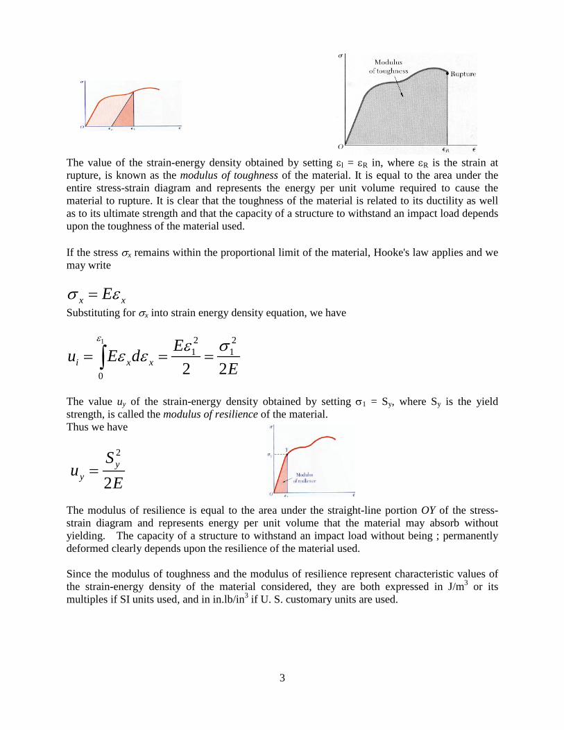
strain-energy density ui is expressed in units obtained by dividing its of energy by units of volume. Thus, if SI metric units are used, strain-energy density is expressed in J/m3 or its multiples kJ/m3 and MJ/m3; if U. S. customary units are used, it is expressed in in.lb/in3. The strain-energy density ui is to the area under the stress-strain curve, measured from εx = 0 to ε1. If the material is unloaded, the stress returns to zero, but there permanent deformation represented by the strain εp, and only the .portion of the strain energy per unit volume corresponding to the triangular area may be recovered. The remainder of the energy spent in deforming the material is dissipated in the form of heat.
3
The value of the strain-energy density obtained by setting εl = εR in, where εR is the strain at rupture, is known as the modulus of toughness of the material. It is equal to the area under the entire stress-strain diagram and represents the energy per unit volume required to cause the material to rupture. It is clear that the toughness of the material is related to its ductility as well as to its ultimate strength and that the capacity of a structure to withstand an impact load depends upon the toughness of the material used. If the stress σx remains within the proportional limit of the material, Hooke's law applies and we may write
x xEσ ε= Substituting for σx into strain energy density equation, we have
1 2 21 1
0 2 2i x xEu E d
E
ε ε σε ε= = =∫
The value uy of the strain-energy density obtained by setting σ1 = Sy, where Sy is the yield strength, is called the modulus of resilience of the material. Thus we have
2
2y
y
Su
E=
The modulus of resilience is equal to the area under the straight-line portion OY of the stress-strain diagram and represents energy per unit volume that the material may absorb without yielding. The capacity of a structure to withstand an impact load without being ; permanently deformed clearly depends upon the resilience of the material used. Since the modulus of toughness and the modulus of resilience represent characteristic values of the strain-energy density of the material considered, they are both expressed in J/m3 or its multiples if SI units used, and in in.lb/in3 if U. S. customary units are used.

4
Elastic strain energy for normal stress Since the rod considered in the before was subject uniformly distributed stresses, the strain-energy density was constant; throughout the rod and could be defined as the ratio Ui/V of the, energy Ui and the volume V of the rod. In a structural element or machine part with a non-uniform stress distribution, the strain-energy density ui may be defined by considering the strain energy density of a small element of material of volume V and thus ui may be defined by considering the strain energy of a small element of material of volume ΔV and writing
i0
dUlim or dV
ii V
UuV∆ →
∆=
∆
The expressions obtained for ui before is valid and the strain-energy density ui will generally vary from point to point
For values of σx within the proportional limit σx = Eεx we write
2 2
0 2 2
x
x xi x x
Eu E dE
ε ε σε ε= = =∫
The value of the strain energy Ui of a body subjected to uni-axial normal stresses may be obtained as
2
2x
iU dVE
σ= ∫
The expression obtained is valid only for elastic deformation and is referred as the elastic strain energy of the body.
Strain Energy under uniaxial loading
When a rod is subjected to centric axial loading, the normal stress σx may be assumed uniformly distributed in any given transverse section. Denoting A the area of the section located at a distance x from the end B of the rod and P the internal force in that section, we write σx = P/A.
5
Thus
2
22iPU dVEA
= ∫ dV = A dx
2
2iPU dVEA
= ∫
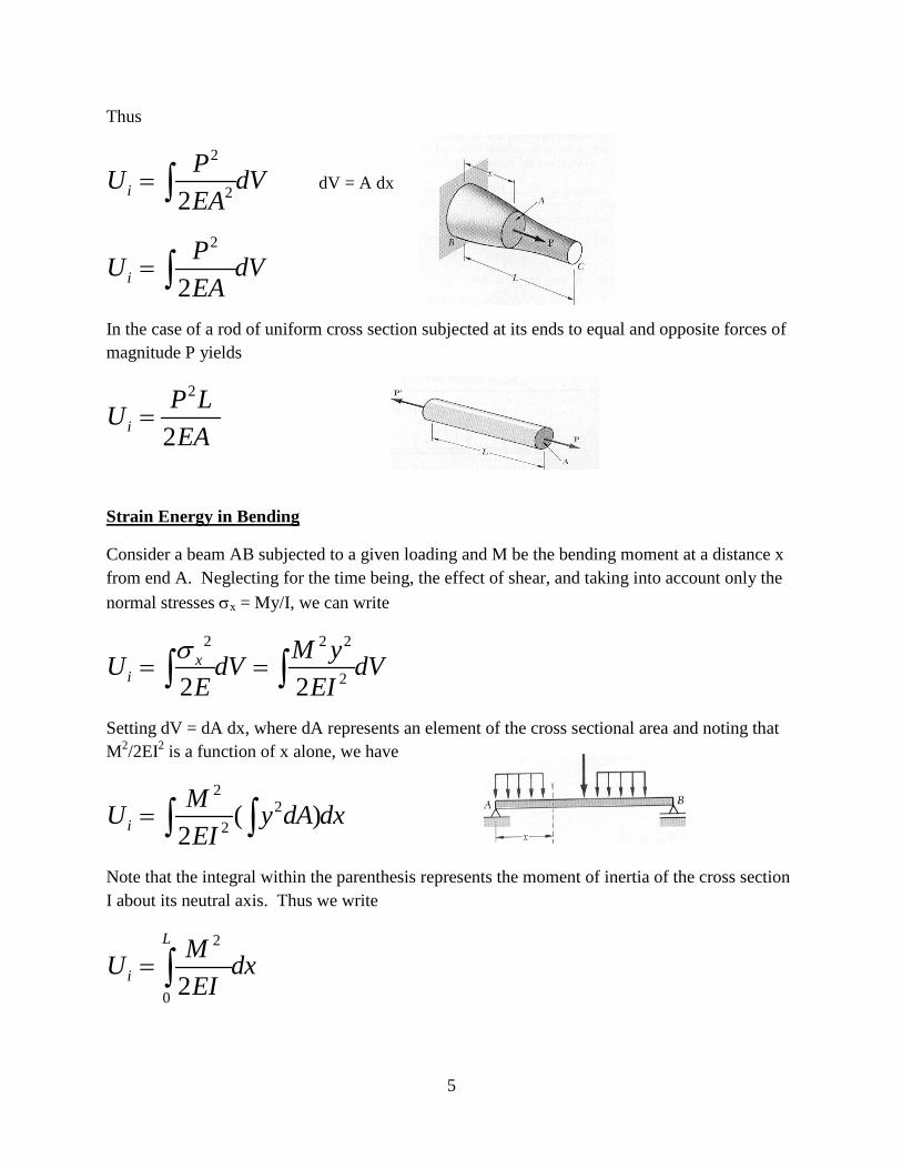
In the case of a rod of uniform cross section subjected at its ends to equal and opposite forces of magnitude P yields
2
2iP LUEA
=
Strain Energy in Bending
Consider a beam AB subjected to a given loading and M be the bending moment at a distance x from end A. Neglecting for the time being, the effect of shear, and taking into account only the normal stresses σx = My/I, we can write
2 2 2
22 2x
iM yU dV dV
E EIσ
= =∫ ∫
Setting dV = dA dx, where dA represents an element of the cross sectional area and noting that M2/2EI2 is a function of x alone, we have
22
2 ( )2iMU y dA dxEI
= ∫ ∫
Note that the integral within the parenthesis represents the moment of inertia of the cross section I about its neutral axis. Thus we write
2
0 2
L
iMU dxEI
= ∫

6
Elastic strain energy for shearing stresses
When a material is subjected to plane shearing stresses τxy the strain energy density at a given point may be expressed as
0
xy
i xy xyu dγ
τ γ= ∫
Where γxy is the shearing strain corresponding to τxy. The strain energy is equal to the area under the shear stress-strain diagram.
For values of τxy within the proportional limit, we have τxy = G γxy where G is the modulus of rigidity of the material. Substituting for τxy and performing integration we get
2 21 1 12 2 2i xy xy xy xyu G
Gγ τ γ τ= = =
The value of the strain energy Ui of a body subjected to plane shear stresses may be obtained
idU dViu = Substituting u from the above we can write
2
0 2
Lxy
iU dVG
τ= ∫
Strain energy in Torsion
Consider a shaft BC of length L subjected to one or several twisting moments. Denoting by J the polar moment of inertia of the cross section located at a distance x from B and T the internal torque in that section, and noting that τxy = Tr/J, we have
2 2 2
22 2xy
iTU dV dV
G GJτ ρ
= =∫ ∫
Setting dV = dA dx, where dA represents an element of the cross sectional area, and observing that T2/2GJ2 is a function of x alone, we write
7
( )2
22
0 2
L
iTU dA dxGJ
ρ= ∫ ∫
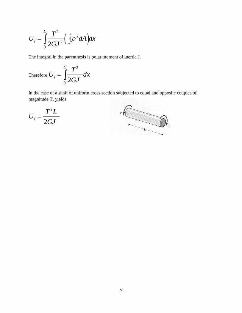
The integral in the parenthesis is polar moment of inertia J.
Therefore 2
0 2
L
iTU dxGJ
= ∫
In the case of a shaft of uniform cross section subjected to equal and opposite couples of magnitude T, yields
2
2iT LUGJ
=
8
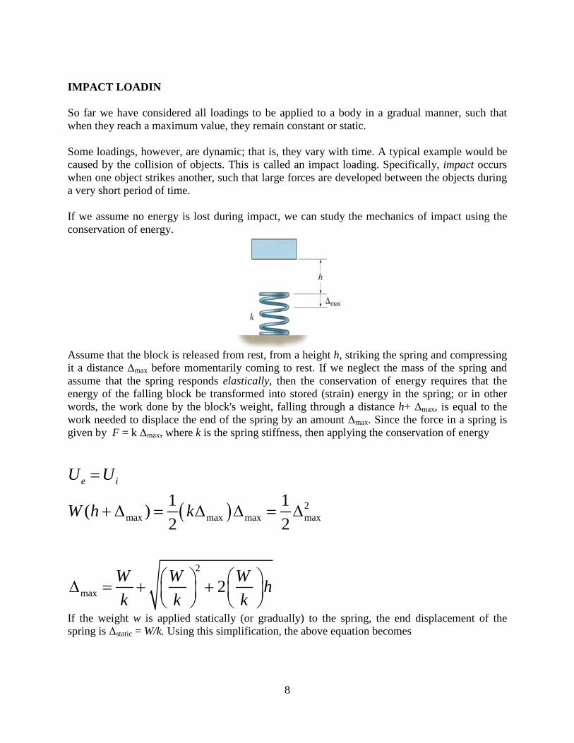
IMPACT LOADIN So far we have considered all loadings to be applied to a body in a gradual manner, such that when they reach a maximum value, they remain constant or static. Some loadings, however, are dynamic; that is, they vary with time. A typical example would be caused by the collision of objects. This is called an impact loading. Specifically, impact occurs when one object strikes another, such that large forces are developed between the objects during a very short period of time. If we assume no energy is lost during impact, we can study the mechanics of impact using the conservation of energy.
Assume that the block is released from rest, from a height h, striking the spring and compressing it a distance Δmax before momentarily coming to rest. If we neglect the mass of the spring and assume that the spring responds elastically, then the conservation of energy requires that the energy of the falling block be transformed into stored (strain) energy in the spring; or in other words, the work done by the block's weight, falling through a distance h+ Δmax, is equal to the work needed to displace the end of the spring by an amount Δmax. Since the force in a spring is given by F = k Δmax, where k is the spring stiffness, then applying the conservation of energy
( ) 2max max max max
1 1( )2 2
e iU U
W h k
=
+ ∆ = ∆ ∆ = ∆
2
max 2W W W hk k k
∆ = + +
If the weight w is applied statically (or gradually) to the spring, the end displacement of the spring is Δstatic = W/k. Using this simplification, the above equation becomes

9
( )2max
max
2
1 1 2
static static static
staticstatic
h
h
∆ = ∆ + ∆ + ∆
∆ = ∆ + + ∆
Once Δmax is computed, the maximum force applied to the spring can be determined from Fmax = kΔmax We should note that this force and associated displacement occur only at an instant. Provided the block does not rebound off the spring, it will continue to vibrate until the motion dampens out and the block assumes the static position, Δstatic Note also that if the block is held just above the spring, h = 0, and dropped, then, the maximum displacement of the block is Δmax
= 2Δstatic
Using a similar analysis, it is also possible to determine the maximum displacement of the end of the spring if the block is sliding on a smooth horizontal surface with a known velocity v just before it collides with the spring, as shown in the figure
Here the block's kinetic energy (1/2(W/g)v2) is transformed into stored energy in the spring. Hence,
10
2 2max
2
max
1 12 2
e iU U
W vg
Wvgk
=
= ∆
∆ =
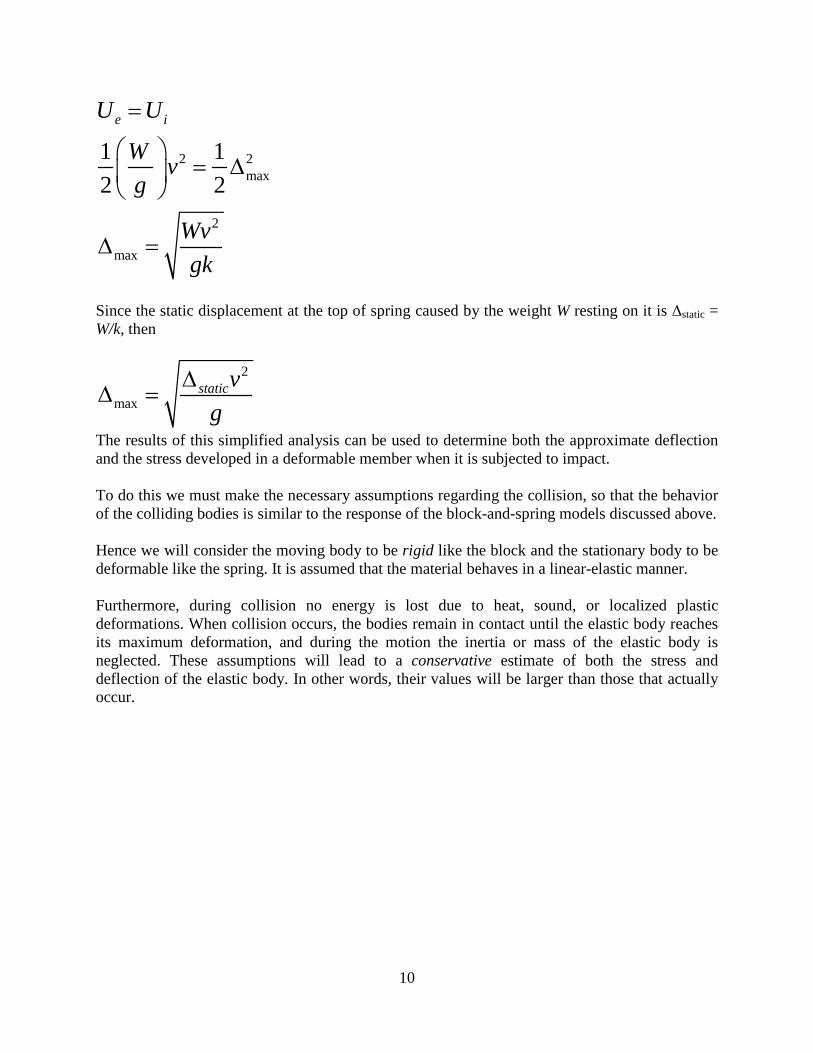
Since the static displacement at the top of spring caused by the weight W resting on it is Δstatic = W/k, then
2
maxstaticvg
∆∆ =
The results of this simplified analysis can be used to determine both the approximate deflection and the stress developed in a deformable member when it is subjected to impact. To do this we must make the necessary assumptions regarding the collision, so that the behavior of the colliding bodies is similar to the response of the block-and-spring models discussed above. Hence we will consider the moving body to be rigid like the block and the stationary body to be deformable like the spring. It is assumed that the material behaves in a linear-elastic manner. Furthermore, during collision no energy is lost due to heat, sound, or localized plastic deformations. When collision occurs, the bodies remain in contact until the elastic body reaches its maximum deformation, and during the motion the inertia or mass of the elastic body is neglected. These assumptions will lead to a conservative estimate of both the stress and deflection of the elastic body. In other words, their values will be larger than those that actually occur.
11
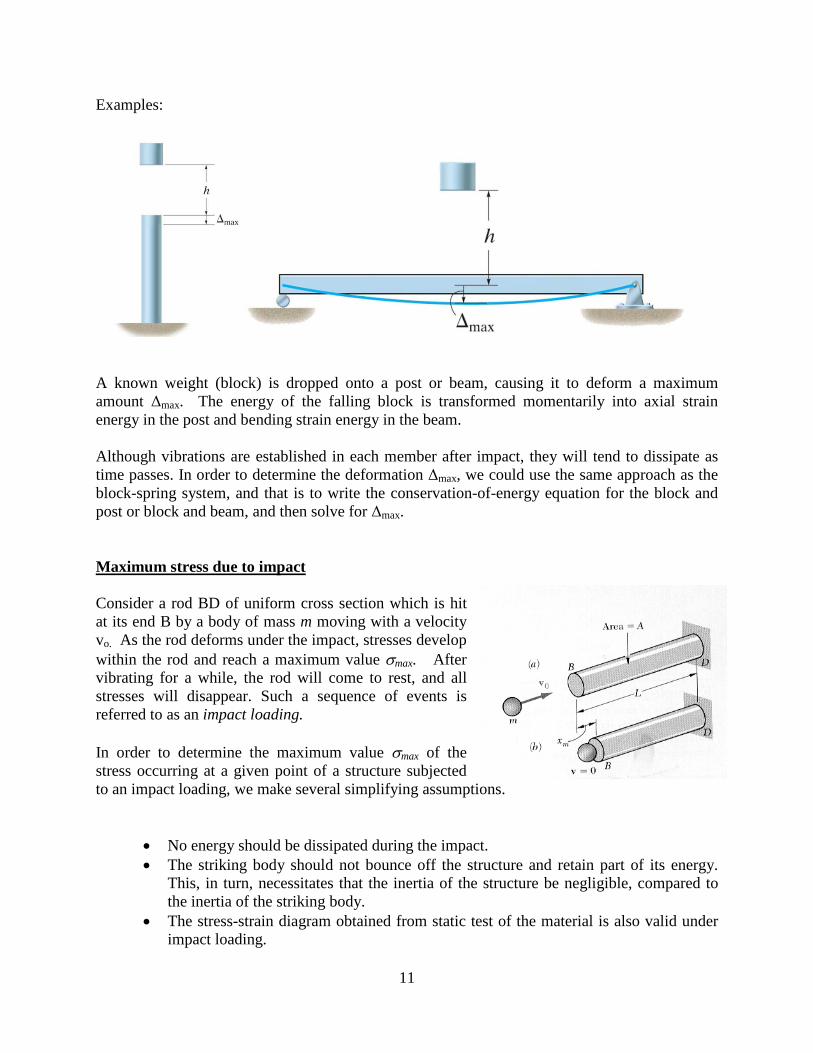
Examples:
A known weight (block) is dropped onto a post or beam, causing it to deform a maximum amount Δmax. The energy of the falling block is transformed momentarily into axial strain energy in the post and bending strain energy in the beam. Although vibrations are established in each member after impact, they will tend to dissipate as time passes. In order to determine the deformation Δmax, we could use the same approach as the block-spring system, and that is to write the conservation-of-energy equation for the block and post or block and beam, and then solve for Δmax. Maximum stress due to impact Consider a rod BD of uniform cross section which is hit at its end B by a body of mass m moving with a velocity vo. As the rod deforms under the impact, stresses develop within the rod and reach a maximum value σmax. After vibrating for a while, the rod will come to rest, and all stresses will disappear. Such a sequence of events is referred to as an impact loading. In order to determine the maximum value σmax of the stress occurring at a given point of a structure subjected to an impact loading, we make several simplifying assumptions.
• No energy should be dissipated during the impact. • The striking body should not bounce off the structure and retain part of its energy.
This, in turn, necessitates that the inertia of the structure be negligible, compared to the inertia of the striking body.
• The stress-strain diagram obtained from static test of the material is also valid under impact loading.
12
In practice, neither of these requirements is satisfied, and only part of the kinetic energy of the striking body is actually transferred to the structure. Thus, assuming that all of the kinetic energy of the striking body is transferred to the structure leads to a conservative design of that structure. Thus, for elastic deformation of the structure, we may express the maximum value of the strain energy as
2max
max 2U dV
Eσ
= ∫
In the case of the uniform rod of the maximum stress σmax has the same value throughout the rod,
2max
max 2VU
Eσ
=
There fore Maximum Kinetic energy of the mass = Maximum strain energy of the rod
22 max1
2 2oVmv
Eσ
=
Solving for σmax we get
2max
max2 oU E mv E
V Vσ = =
It can be seen that selecting a rod with a large volume V and a low modulus of elasticity E will result in a smaller value of maximum stress σmax for a given impact loading. In most problems, the distribution of stresses in the structure is not uniform, and the above formula does not apply. It is then convenient to determine the static load Pmax which would produce the same strain energy as the impact loading, and compute from Pmax the corresponding value σmax of the largest stress occurring in the structure. A structure designed to withstand effectively an impact load should
1 Have a large volume 2 Be made of a material with a low modulus of elasticity and a high: yield strength. 3 Be shaped so that the stresses are distributed as evenly as possible: throughout the
structure