o b o tics e uto Advances in Robotics +Adv Robot Autom c m ... · continuous process by using...
4
Volume 5 • Issue 3 • 1000156 Adv Robot Autom, an open access journal ISSN: 2168-9695 OMICS International Research Article Advances in Robotics & Automation A d v a n c e s i n R o b o t i c s & A u t o m a t i o n ISSN: 2168-9695 Maghsadhagh, Adv Robot Autom 2016, 5:3 DOI: 10.4172/2168-9695.1000156 Keywords: Microcontroller; PID; Microchip technology; PIC Introduction ese days many people are aware of the importance of controlling process in our factories and housekeeping. One of the most important factors that are vital for motors and pumps in factories, is the times the motors are in stand by mood and the operator wants to turn on them. is can cause a huge current in the rotors even eight times more than functional current. By being aware about this huge current, we have to be avoided about turning off motors. Now we can use a common controller like PID that can reduce the damages impressively. But determining reasonable factors for PID is very vital for the system which is designed to be able to control a continuous system that will be interrupted by one or more output valves. Aſter designing a probable soſtware, we have to find a capable hardware such as motor driver, microcontroller and what it needs to run properly. PIC is a family of microcontrollers made by Microchip Technology, derived from the PIC1650 originally developed by General Instrument's Microelectronics Division. e name PIC initially referred to Peripheral Interface Controller. e first parts of the family were available in 1976; by 2013 the company had shipped more than twelve billion individual parts, used in a wide variety of embedded systems. In 2000, Microchip introduced the PIC18 architecture. Unlike the 17 series, it has proven to be very popular, with a large number of device variants presently in manufacture. In contrast to earlier devices, which were more oſten than not programmed in assembly, C has become the predominant development language. Because of this popularity this type of PICs is chosen (Figure 1). As a bridge to the real world from assembly world, a driver is needed, which transfers the programs and orders from microcontroller to the pomp input. PWM helps us to control the pomp continuously and properly [1]. PID Controller in Mathematical Format A proportional integral derivative controller is a control loop feedback mechanism commonly used in industrial control systems. A PID controller continuously calculates an error value e(t) as the difference between a desired set point and a measured process variable. e controller attempts to minimize the error over time by adjustment of a control variable u(t) such as the position of a control valve, a damper, or the power supplied to a heating element, to a new value determined by a weighted sum: t 0 () *u(t) e(t) e(t)dt i d de t Kp K K dt = + ∫ + Where K p , K i , K d , all non-negative, denote the coefficients for the proportional, integral, and derivative terms, respectively (sometimes denoted P, I, and D). In this model: • P accounts for present values of the error. For example, if the error is large and positive, the control output will also be large and positive. *Corresponding author: Ardavan Maghsadhagh, Istanbul Technical University, Master, Faculty of Electrical Engineering, İstanbul, Turkey, Tel: 902122853030; E-mail: [email protected] Received September 27, 2016; Accepted November 01, 2016; Published November 04, 2016 Citation: Maghsadhagh A (2016) Implementation of PID Controller by Microcontroller of PIC (18 Series) and Controlling the Height of Liquid in Sources. Adv Robot Autom 5: 156. doi: 10.4172/2168-9695.1000156 Copyright: © 2016 Maghsadhagh A. This is an open-access article distributed under the terms of the Creative Commons Attribution License, which permits unrestricted use, distribution, and reproduction in any medium, provided the original author and source are credited. Abstract This paper presents a comprehensive analysis of PID controller and implementation of PID by the microcontroller of PIC and the use of PWM in the DC controlling processes. First of all we use the PID controller to control a continuous process by using reasonable factors (P, I, D) in PID and PIC (18f452) will help us during this period of time and after that producing an adequate PWM signal for the use of our pomp to take the motor under our control. We have to use an appropriate IC such as L298 which is a motor driver. Implementation of PID Controller by Microcontroller of PIC (18 Series) and Controlling the Height of Liquid in Sources Ardavan Maghsadhagh* Istanbul Technical University, Master, Faculty of Electrical Engineering, İstanbul, Turkey Figure 1: Type of PICs.
Transcript of o b o tics e uto Advances in Robotics +Adv Robot Autom c m ... · continuous process by using...
Volume 5 • Issue 3 • 1000156Adv Robot Autom, an open access journalISSN: 2168-9695
OMICS InternationalResearch Article
Advances in Robotics & AutomationAd
vanc
es in
Robotics & Automation
ISSN: 2168-9695
Maghsadhagh, Adv Robot Autom 2016, 5:3DOI: 10.4172/2168-9695.1000156
Keywords: Microcontroller; PID; Microchip technology; PIC
IntroductionThese days many people are aware of the importance of controlling
process in our factories and housekeeping. One of the most important factors that are vital for motors and pumps in factories, is the times the motors are in stand by mood and the operator wants to turn on them. This can cause a huge current in the rotors even eight times more than functional current. By being aware about this huge current, we have to be avoided about turning off motors. Now we can use a common controller like PID that can reduce the damages impressively. But determining reasonable factors for PID is very vital for the system which is designed to be able to control a continuous system that will be interrupted by one or more output valves.
After designing a probable software, we have to find a capable hardware such as motor driver, microcontroller and what it needs to run properly. PIC is a family of microcontrollers made by Microchip Technology, derived from the PIC1650 originally developed by General Instrument's Microelectronics Division. The name PIC initially referred to Peripheral Interface Controller. The first parts of the family were available in 1976; by 2013 the company had shipped more than twelve billion individual parts, used in a wide variety of embedded systems. In 2000, Microchip introduced the PIC18 architecture. Unlike the 17 series, it has proven to be very popular, with a large number of device variants presently in manufacture. In contrast to earlier devices, which were more often than not programmed in assembly, C has become the predominant development language. Because of this popularity this type of PICs is chosen (Figure 1).
As a bridge to the real world from assembly world, a driver is needed, which transfers the programs and orders from microcontroller to the pomp input. PWM helps us to control the pomp continuously and properly [1].
PID Controller in Mathematical FormatA proportional integral derivative controller is a control loop
feedback mechanism commonly used in industrial control systems. A PID controller continuously calculates an error value e(t) as the difference between a desired set point and a measured process variable. The controller attempts to minimize the error over time by adjustment of a control variable u(t) such as the position of a control valve, a damper, or the power supplied to a heating element, to a new value determined by a weighted sum:
t0
( )*u(t) e(t) e(t)dti dde tKp K K
dt= + ∫ +
Where Kp, Ki, Kd, all non-negative, denote the coefficients for the proportional, integral, and derivative terms, respectively (sometimes denoted P, I, and D). In this model:
• P accounts for present values of the error. For example, if theerror is large and positive, the control output will also be largeand positive.
*Corresponding author: Ardavan Maghsadhagh, Istanbul Technical University,Master, Faculty of Electrical Engineering, İstanbul, Turkey, Tel: 902122853030; E-mail: [email protected]
Received September 27, 2016; Accepted November 01, 2016; Published November 04, 2016
Citation: Maghsadhagh A (2016) Implementation of PID Controller by Microcontroller of PIC (18 Series) and Controlling the Height of Liquid in Sources. Adv Robot Autom 5: 156. doi: 10.4172/2168-9695.1000156
Copyright: © 2016 Maghsadhagh A. This is an open-access article distributed under the terms of the Creative Commons Attribution License, which permits unrestricted use, distribution, and reproduction in any medium, provided the original author and source are credited.
AbstractThis paper presents a comprehensive analysis of PID controller and implementation of PID by the microcontroller
of PIC and the use of PWM in the DC controlling processes. First of all we use the PID controller to control a continuous process by using reasonable factors (P, I, D) in PID and PIC (18f452) will help us during this period of time and after that producing an adequate PWM signal for the use of our pomp to take the motor under our control. We have to use an appropriate IC such as L298 which is a motor driver.
Implementation of PID Controller by Microcontroller of PIC (18 Series) and Controlling the Height of Liquid in SourcesArdavan Maghsadhagh*Istanbul Technical University, Master, Faculty of Electrical Engineering, İstanbul, Turkey
Figure 1: Type of PICs.
Citation: Maghsadhagh A (2016) Implementation of PID Controller by Microcontroller of PIC (18 Series) and Controlling the Height of Liquid in Sources. Adv Robot Autom 5: 156. doi: 10.4172/2168-9695.1000156
Page 2 of 4
Volume 5 • Issue 3 • 1000156Adv Robot Autom, an open access journalISSN: 2168-9695
• I accounts for past values of the error. For example, if thecurrent output is not sufficiently strong, error will accumulateover time, and the controller will respond by applying astronger action.
• D accounts for possible future values of the error, based on itscurrent rate of change. Some applications can be controlled byPI in the absence of D factor or PD in the absence of I factor(Figure 2).
To approach to the factors of PID we can use Ziegler-Nichols method which is a heuristic method of tuning a PID controller. It is performed by setting I (integral) and D (derivative) gains to zero. The "P" gain, Kp is then increased (from zero) until it reaches the ultimate gain Ku, at which the output of the control loop has stable and consistent oscillations. Ku and the oscillation period Tu are used to set the P, I, and D gains depending on the type of controller used: (Table 1).
Discrete-time PID algorithm
The PID mathematical equation must be transferred to digital equation which will be understandable for the PIC. It can be changed with a good approximation like the below equation, for digital implementation, we are more interested in a Z-transform of (*):
11U(z) (1 z ) (z)
1 zi
p dKK K E−
−
= + + − − By rearranging once again:
( ) ( ) 1 2
1
2 zU(z) (z)
1p i d p d dK K K K K K z
Ez
− −
−
+ + + − − + =
−
1 p i dK K K K= + +
2 p dK K 2K=− −
3 dK K=
It can be written:
( ) ( ) ( )1 1 21 2 3z zU z z U z K K K E z− − − − = + +
Which can be converted to:
1 2 3u[k] u[k 1] K u[k] K u[k 1] K u[k 2]= − + ∗ + ∗ − + ∗ −
Now a digital output must be transferred to an analog output, to be understandable for the pomp.
Pulse Width Modulation (PWM)DC motors were the first type widely used, since they could be
powered from existing direct-current lighting power distribution systems. A DC motor's speed can be controlled over a wide range, using either a variable supply voltage or by changing the strength of current in its field windings [2,3].
( )2a
rme e
V Rù TK Kφ φ
= +
As it can be seen from the equal, DC motors speed can be controlled by three parameter: voltage (V), flux (𝜙), resistance of motor (Ra).
In the past one of the most common ways for controlling DC motors is using a kind of variable resistance. This kind of control have been used in old sewing machines (Figure 3).
But it is not an economical way to control a DC motor because of its energy losses. So engineers had to find out a new controlling method [4,5].
First of all, engineers introduced Duty Cycle term. A duty cycle is the percentage of one period in which a signal or system is active. Duty cycle is commonly expressed as a percentage or a ratio. A period is the time it takes for a signal to complete an on-and-off cycle. As a formula, a duty cycle may be expressed as:
100PWDT
= ×
where D is the duty cycle, PW is the pulse width, and T is the total period of the signal. Thus, a 60% duty cycle means the signal is on 60% of the time but off 40% of the time. So the motor can be controlled precisely with high output (Figure 4).
Figure 3: Voltage -ωm Plot.
Figure 4: Resistance - ωm Plot.
Figure 2: PID Conduct.
Control Type Kp Ki KdP 0.5Ku - -PI 0.45Ku 1.2Kp/Tu -
PID 0.6 Ku 2Kp/Tu 8Kp/Tu
Table 1: Ziegler–Nichols method.

Citation: Maghsadhagh A (2016) Implementation of PID Controller by Microcontroller of PIC (18 Series) and Controlling the Height of Liquid in Sources. Adv Robot Autom 5: 156. doi: 10.4172/2168-9695.1000156
Page 3 of 4
Volume 5 • Issue 3 • 1000156Adv Robot Autom, an open access journalISSN: 2168-9695
A technique to take analog output from digital input in various systems.
The pulse can be produced by many methods such as hardware techniques (ICs like 555 timer IC) or software methods.
Since our microcontrollers do not have the acceptable power to run a motor, a driver is needed to make the analog output capable to operational (Figure 5).
DriverThe pulse which is on the microcontroller port is not able to run
a motor such as a pomp. So a motor driver such as L298 is needed (Figure 6).
The L298 is an integrated monolithic circuit in a 15-lead Multiwatt and PowerSO20 packages. It is a high voltage, high current dual full-bridge driver designed to accept standard TTL logic levels and drive inductive loads such as relays, solenoids, DC and stepping motors. Two enable inputs are provided to enable or disable the device independently of the input signals. The emitters of the lower transistors of each bridge are connected together and the corresponding external terminal can be used for the connection of an external sensing resistor. An additional supply input is provided so that the logic works at a lower voltage (Figure 7).
It can run two motors (50V, 2A) in the same time or its outputs can be used to activate one motor with high current whose form is used in this project.
Height SensorStrain gage sensors are one the most popular sensors which are
used in industrial applications (Figure 8).
A strain gauge (or strain gage) is a device used to measure strain on an object. The gauge is attached to the object by a suitable adhesive, such as cyanoacrylate. As the object is deformed, the foil is deformed, causing its electrical resistance to change. This resistance change, usually measured using a Wheatstone bridge, is related to the strain by the quantity known as the gauge factor (Figure 9).
So VG will be changed by the changing of R2 and a resistance factor will be a voltage factor and understandable for the microcontroller.
It is very important that a low pass filter (such as a capacitance) is vital for the output of the sensor since there are various kinds of noises in Lab.
ProgrammingOne of the most important parts of the project is programming
process which can be done by C language. On the other hand, Flowcode
Figure 5: Duty Cycle Process.
Figure 6: L298 a Similar Motor Driver.
Figure 7: Electronic Circuit of L298.
Figure 8: Strain Gauge schematic.
Figure 9: Wheatstone Bridge.
Citation: Maghsadhagh A (2016) Implementation of PID Controller by Microcontroller of PIC (18 Series) and Controlling the Height of Liquid in Sources. Adv Robot Autom 5: 156. doi: 10.4172/2168-9695.1000156
Page 4 of 4
Volume 5 • Issue 3 • 1000156Adv Robot Autom, an open access journalISSN: 2168-9695
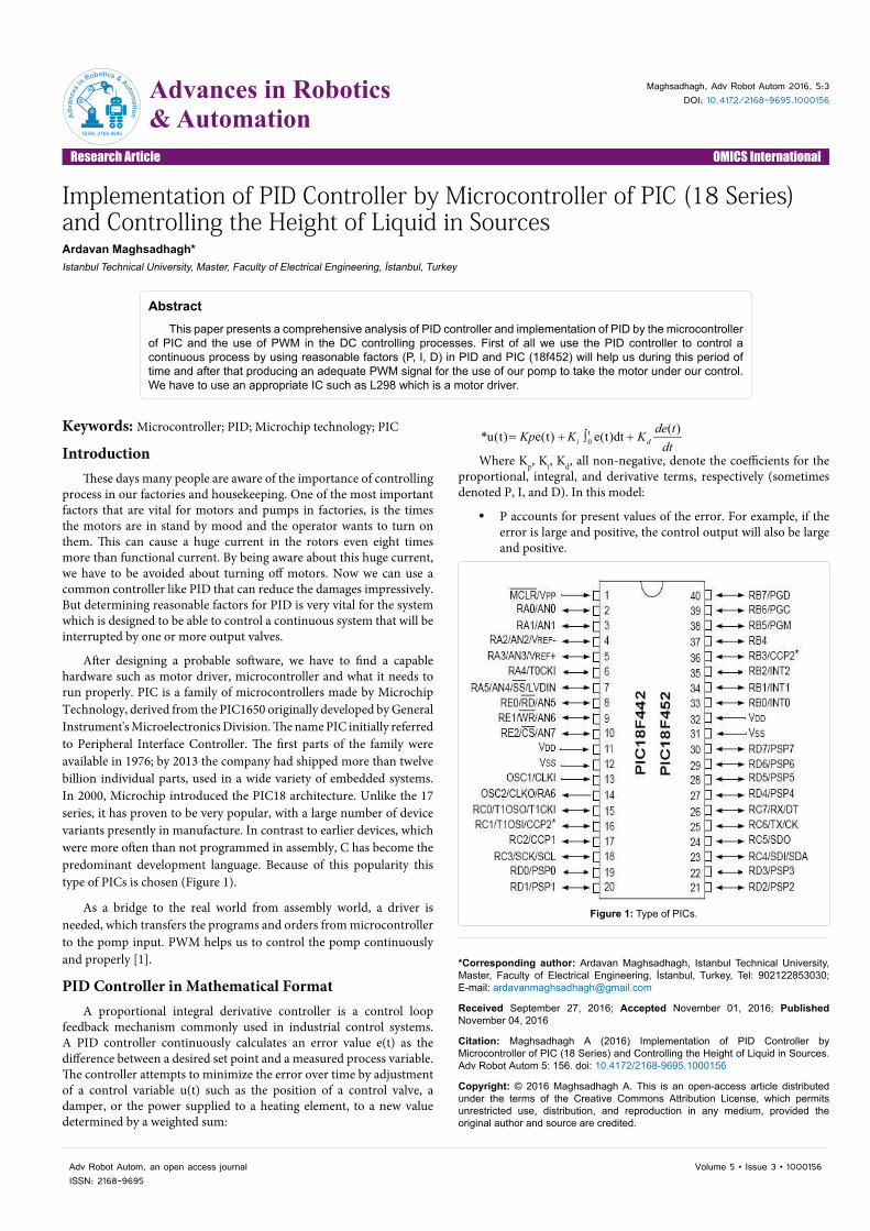
programming software is recommended to whom does not know C language very well (Figure 10).
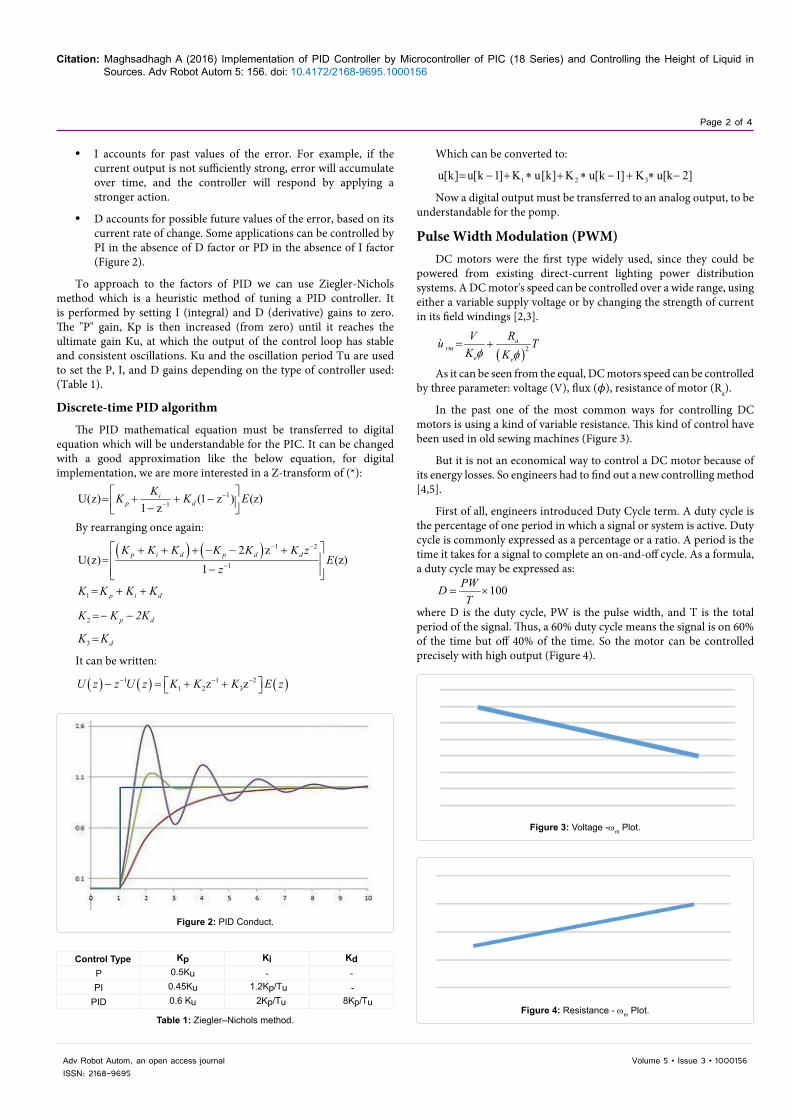
Practical Industrial Application of PID ControllerIn industrial country, particularly in oily oil-rich countries,
engineers implement PID controller by PICs or PLCs to control the height of oil in tanks. Controlling the height of petroleum liquid in tanks of refineries is one of the most important factors of safety in oil industry.
As it has been said, many practical controllers had been used for many years to control turbulences in various systems, but PID controller has been very successful until today either in industrial applications or nonindustrial (Figure 11).
ConclusionIn this paper, implementation of PID controller, which has been
one the most popular controller, is discussed. Implementing by PIC microcontroller, one of the high-wrought microcontrollers that is used in factories and industrial places commonly. First of all, a digital equal of PID is needed to be understandable for the microcontroller. The digital output will not be fit for the analog world and PWM is designed to control the pomp properly. After all every project needs some sensors to make the brain of the project (microcontroller) be aware about interrupts. Using sensors in the right bridge is another vital point.
References
1. Katsuhiko Ogata: Linear Control.
2. Varodom Toochinda (2011) Digital PID Controllers.
3. Peterchev AV, Sanders R (2006) Digital Pulse-Width Modulation Control in Power Electronic Circuits: Theory and Applications.
4. Microchip Technology, PIC18f452 catalog.
5. Sengolrajan T, Shanthi B (2016) Comparative Analysis of Trapezoidal PWM Strategies for three phase Trinary Source nine Level Inverter In: Journal of Electrical Engineering.
Figure 11: An Industrial Schematic of PID controller In Tanks.
Figure 10: Proteus Schematic of Project.