Numerical optimization of a centrifugal pump impeller with ... · PDF fileInternational Review...
12
International Review of Mechanical Engineering (I.RE.M.E.), Vol. xx, n. x Manuscript received January 2016, revised xxxxx 2016 Copyright © 2016 Praise Worthy Prize S.r.l. - All rights reserved Numerical optimization of a centrifugal pump impeller with splitter blades running in reverse mode Ioannis Kassanos 1 , Marios Chrysovergis 1 , John Anagnostopoulos 1 , George Charalampopoulos 2 , Stamelos Rokas 2 , Stavros Lekanidis 2 , Ioannis Kontominas 2 and Dimitris Papantonis 1 Abstract – In this paper the numerical modeling and optimization of a centrifugal pump impeller running in reverse operation is presented. In order to determine the operating envelope of the turbine as well as validate the numerical results, simulations were initially performed at normal pump operation. By comparing the numerical with the experimental values, a relatively good correlation could be achieved. The turbine operating point was determined using empirical correlations, which were also validated by the numerical performance curves obtained from multiple operating point simulations. This information is used to validate the numerical approach and assumptions in order to be applied for the optimization of the impeller in turbine operation. Subsequently, a parametric study is performed comparing the relative effect in performance of various design modifications, such as the inlet edge shape, the meridional channel width, the number of vanes, and the effect of splitter blades. Using the previous results as guidelines, the numerical optimization of the runner is performed using two optimization algorithms. In the first, only the blade shape was allowed to change while the rotational speed was also included while meridional contour of the runner was maintained constant in order to accommodate the available spiral casing dimensions. In the second optimization, the runner diameter was also included. From the results of the optimization, an overall increase in turbine efficiency of approximately 2.7% could be achieved. Keywords: Hydropower, Pump as Turbine, Impeller Design, Numerical Modeling, Optimization I. Introduction The continuous increase of cost of conventional fuels has made the development of small and mini hydroelectric plants financially viable. However, the specific cost per kW of such units can still be relatively large. A popular alternative, for the limitation of this cost has been the use of centrifugal pumps as turbines (PAT) [1], [2]. The advantage of such an approach is the simple construction, the ability to use standard of the shelve components with minimal modifications and the benefit from decentralized electricity generation [1]-[4]. These characteristics have increased their popularity over the years, especially when used in mini hydro electric schemes in rural and developing regions, in which the success of a project strongly relies on the initial costs [3]. Although, substantial benefits are associated with the use of pumps as turbines, there are several important disadvantages that shouldn't be ignored. Most importantly, the efficiency of such machines is significantly lower compared to the equivalent in pump operation, which may amount up to -8.5% of pump efficiency [1]. Another issue with using PAT is the difficulty to predict the actual performance of a standard pump in turbine mode. Several efforts have been made in the past using empirical correlations [1], CFD or experimental measurements [4]-[7], but still not enough information is available. This lack of information may discourage the use of pumps as turbines for a cost effective energy generation solution. A significant disadvantage of PAT is the inexistence of guide vanes and of a flow control mechanism, which limits the operating envelope and inhibits the ability to efficiently control the operating point. This highlights the importance of improving their design in order to maximize energy productivity over an extended operating range. One way to achieve this is by increasing the hydraulic efficiency of the runner at a desired operating point. A recent approach that has been utilized in high head Francis turbines and centrifugal pumps has been the incorporation of splitter blades in the runner. In various studies, improvements on the head and efficiency curves have been reported [8]-[10], while an improvement of the unsteady characteristics has
Transcript of Numerical optimization of a centrifugal pump impeller with ... · PDF fileInternational Review...
International Review of Mechanical Engineering (I.RE.M.E.), Vol. xx, n. x
Manuscript received January 2016, revised xxxxx 2016 Copyright © 2016 Praise Worthy Prize S.r.l. - All rights
reserved
Numerical optimization of a centrifugal pump impeller with
splitter blades running in reverse mode
Ioannis Kassanos1, Marios Chrysovergis1, John Anagnostopoulos1, George Charalampopoulos2, Stamelos Rokas2, Stavros Lekanidis2, Ioannis Kontominas2 and Dimitris Papantonis1
Abstract – In this paper the numerical modeling and optimization of a centrifugal pump
impeller running in reverse operation is presented. In order to determine the operating
envelope of the turbine as well as validate the numerical results, simulations were initially
performed at normal pump operation. By comparing the numerical with the experimental
values, a relatively good correlation could be achieved . The turbine operating point was
determined using empirical correlations, which were also validated by the numerical
performance curves obtained from multiple operating point simulations. This information is
used to validate the numerical approach and assumptions in order to be applied for the
optimization of the impeller in turbine operation. Subsequently, a parametric study is
performed comparing the relative effect in performance of various design modifications, such
as the inlet edge shape, the meridional channel width, the number of vanes, and the effect of
splitter blades. Using the previous results as guidelines, the numerical optimization of the
runner is performed using two optimization algorithms. In the first, only the blade shape was
allowed to change while the rotational speed was also included while meridional contour of
the runner was maintained constant in order to accommodate the available spiral casing
dimensions. In the second optimization, the runner diameter was also included. From the
results of the optimization, an overall increase in turbine efficiency of approximately 2.7%
could be achieved.
Keywords: Hydropower, Pump as Turbine, Impeller Design, Numerical Modeling, Optimization
I. Introduction
The continuous increase of cost of conventional
fuels has made the development of small and mini
hydroelectric plants financially viable. However, the
specific cost per kW of such units can still be
relatively large. A popular alternative, for the
limitation of this cost has been the use of centrifugal
pumps as turbines (PAT) [1], [2]. The advantage of
such an approach is the simple construction, the
ability to use standard of the shelve components with
minimal modifications and the benefit from
decentralized electricity generation [1]-[4]. These
characteristics have increased their popularity over
the years, especially when used in mini hydro electric
schemes in rural and developing regions, in which the
success of a project strongly relies on the initial costs
[3].
Although, substantial benefits are associated with
the use of pumps as turbines, there are several
important disadvantages that shouldn't be ignored.
Most importantly, the efficiency of such machines is
significantly lower compared to the equivalent in
pump operation, which may amount up to -8.5% of
pump efficiency [1]. Another issue with using PAT is
the difficulty to predict the actual performance of a
standard pump in turbine mode. Several efforts have
been made in the past using empirical correlations
[1], CFD or experimental measurements [4]-[7], but
still not enough information is available. This lack of
information may discourage the use of pumps as
turbines for a cost effective energy generation
solution.
A significant disadvantage of PAT is the
inexistence of guide vanes and of a flow control
mechanism, which limits the operating envelope and
inhibits the ability to efficiently control the operating
point. This highlights the importance of improving
their design in order to maximize energy productivity
over an extended operating range. One way to
achieve this is by increasing the hydraulic efficiency
of the runner at a desired operating point. A recent
approach that has been utilized in high head Francis
turbines and centrifugal pumps has been the
incorporation of splitter blades in the runner. In
various studies, improvements on the head and
efficiency curves have been reported [8]-[10], while
an improvement of the unsteady characteristics has
I. Kassanos, M. Chrysovergis, J. Anagnostopoulos, G. Charalampopoulos, S. Rokas, S. Lekanidis, I. Kontominas
and D. Papantonis
Copyright © 2016 Praise Worthy Prize S.r.l. - All rights reserved International Review of Mechanical Engineering, Vol.
xx, n. x
also been shown to be achieved [10], [11]. The
cavitation performance of the impeller has also been
reported in [12]. The use of splitter blades has been
shown to favorably modify the pressure distribution
on the blades and at the same time delay the flow
separation in certain operating conditions, which
could facilitate the inception of cavitation [13]. In
pump operation the increase of blade number,
reduces the blade loading and improves cavitation
characteristics, while also leads to an efficiency
increase as the secondary flows within the flow
channel are reduced. In high head machines, in which
the impeller widths are small, compared to the
diameter, the increase of blade number may lead to
an overall reduction in efficiency due to an increase
of hydraulic friction losses. However, in high head
machines the relative velocities are larger, while
additional losses can be induced due to flow
chocking. The use of splitter blades allows the above
to be achieved with a simultaneous limitation of these
unwanted characteristics. A second approach to
improve the performance of centrifugal pumps in
turbine operation is by using an appropriate
optimization procedure [14]-[16] aiming at the
maximization of the hydraulic efficiency of the
individual components of the PAT, and especially the
runner.
This paper deals with the performance
improvement and optimization of a pump impeller,
operated as a turbine. A standard of-the-shelf low
specific speed pump was provided by a local
manufacturer and studied numerically in order to
identify potential areas of improvement and
subsequently, to optimize the performance
characteristics of the pump in turbine operation. The
aim was to develop an efficient and, at the same time,
cost effective solution for low output applications,
such as energy recovery etc. Initially, the pump
performance characteristics were obtained
numerically and compared against the manufacturers’
performance data in order to identify the flow
behavior within the impeller channel at various
operating conditions, to identify potentially
problematic areas of the initial design and to validate
the numerical approach. Subsequently, the initial
design was operated in reverse and simulations were
repeated for various operating conditions. The effect
of various design alterations were investigated
parametrically, and finally the design optimization of
the initial design was performed. Two optimization
approaches were used, in which the parameters
defining the geometry were allowed to vary, while in
the second, the rotational velocity was also used as a
free parameter. In all optimization cycles a constant
meridional profile was considered, which was a
constraint imposed by the geometry of the available
spiral casing. Through this process it was possible to
identify the geometric parameters leading to
improved performances and increase the hydraylic
efficieny of the PAT by 2.7%.
II. Model Description and Design
Variations
The numerical model used in this paper is based
on a low specific speed centrifugal pump with a
design head of 38mWc, flow rate 18m3/h, a rotational
speed of 2900 rpm and 5 impeller blades. In the
following table, the main geometric parameters of the
pump are summarized.
TABLE I
Geometric characteristics of centrifugal pump under
investigation
Parameter Value
Pump Type LDP 32-160
Rotational Speed [rpm] 2900
Impeller width [mm] 5
Impeller diameter [mm] 177
Suction diameter[mm] 53.1
Discharge diameter [mm] 41.1
Motor power [kW] 5.5
As mentioned above, in order to identify
performance improvements through simple
modifications of the existing geometry, five
additional design variations, as listed in table 1, were
considered. Specifically, the effects of the inlet edge
blade profile rounding, the increase of blade number,
the increase of the meridional flow channel width and
the use of splitter blades on turbine performance were
investigated.
TABLE II
Design variations under consideration
Case# Design variation
0 Initial Geometry
1 Inlet edge blade rounding
2 20% width increase
3 6 blades
4 7 blades
5 Splitter blades
III. Blade Parameterization
In order to effectively perform a numerical design
optimization procedure, a suitable means of
parametrically describing the geometry under
investigation, is necessary. The chosen
I. Kassanos, M. Chrysovergis, J. Anagnostopoulos, G. Charalampopoulos, S. Rokas, S. Lekanidis, I. Kontominas
and D. Papantonis
Copyright © 2016 Praise Worthy Prize S.r.l. - All rights reserved International Review of Mechanical Engineering, Vol.
xx, n. x
parameterization must allow for an accurate
description of the runner, with the minimum number
of parameters. In this application the conformal
mapping method was used for the parametric
description of the blades. By assuming a fixed
meridional channel contour (Fig. 1), the mean blade
surface was obtained by using two 5-control point
bezier curves that define the blade angle distribution
along the hub and shroud profiles, respectively.
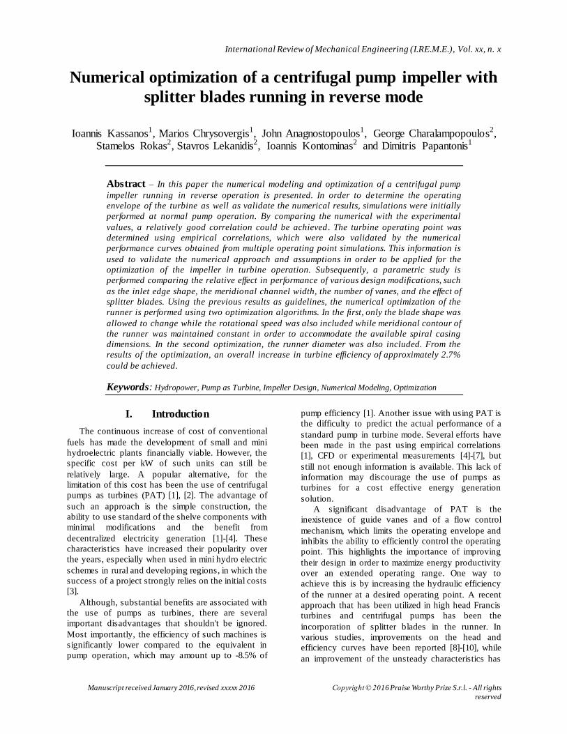
Fig. 1 Meridional channel of runner under investigation
The angle distributions are defined as functions of
the normalized meridional length m/r, as shown in
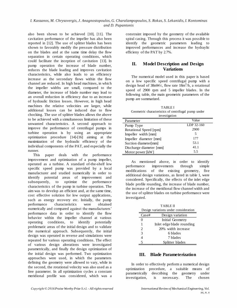
fig. 2. The final pressure and suction surfaces were
obtained after imposing a thickness distribution on
the mean surface of the blade. For the thickness
distribution, a five control point bezier curve was
used fig. 3. As the blade is radial and the runner
width small, one defining curve is enough to fully
describe the blade shape. Each control point was
allowed to vary within a suitable range to allow
feasible design variations to be obtained. The control
points used to describe the blades are presented in
table 3.
Fig. 2 Blade angle distribution along the normalized meridional length
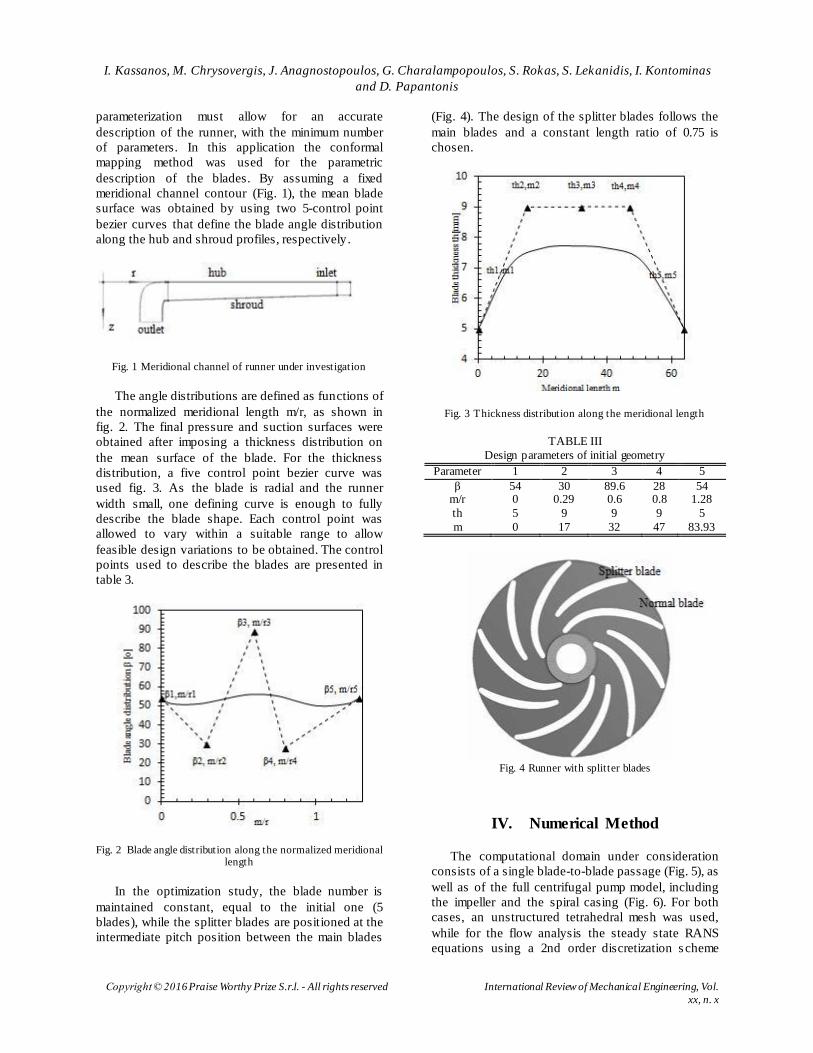
In the optimization study, the blade number is
maintained constant, equal to the initial one (5
blades), while the splitter blades are positioned at the
intermediate pitch position between the main blades
(Fig. 4). The design of the splitter blades follows the
main blades and a constant length ratio of 0.75 is
chosen.
Fig. 3 Thickness distribution along the meridional length
TABLE III
Design parameters of initial geometry
Parameter 1 2 3 4 5
β 54 30 89.6 28 54 m/r 0 0.29 0.6 0.8 1.28
th 5 9 9 9 5
m 0 17 32 47 83.93
Fig. 4 Runner with splitter blades
IV. Numerical Method
The computational domain under consideration
consists of a single blade-to-blade passage (Fig. 5), as
well as of the full centrifugal pump model, including
the impeller and the spiral casing (Fig. 6). For both
cases, an unstructured tetrahedral mesh was used,
while for the flow analysis the steady state RANS
equations using a 2nd order discretization s cheme
I. Kassanos, M. Chrysovergis, J. Anagnostopoulos, G. Charalampopoulos, S. Rokas, S. Lekanidis, I. Kontominas
and D. Papantonis
Copyright © 2016 Praise Worthy Prize S.r.l. - All rights reserved International Review of Mechanical Engineering, Vol.
xx, n. x
and the realizable k-e turbulence model were solved.
The boundary conditions were derived by using a
spiral casing flow simulation where the absolute and
tangential velocity components were obtained and
from suitable empirical correlations that relate the
design flow in turbine mode to the operational
characteristics in pump mode [eq.1], as presented in
[1]. The corresponding boundary conditions were:
inlet flow rate of 29m3/h, zero outlet static pressure,
and rotational speed of 2900 rpm. The commercial
CFD software Ansys fluent was used for all
simulations.
QΤ = QP ∙ 1,2 ∙ (ηP)−0,55 (1)
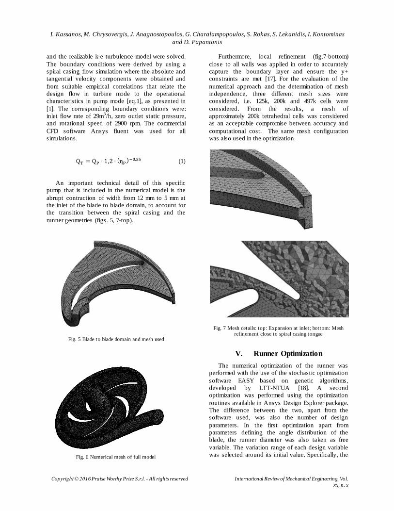
An important technical detail of this specific
pump that is included in the numerical model is the
abrupt contraction of width from 12 mm to 5 mm at
the inlet of the blade to blade domain, to account for
the transition between the spiral casing and the
runner geometries (figs. 5, 7-top).
Fig. 5 Blade to blade domain and mesh used
Fig. 6 Numerical mesh of full model
Furthermore, local refinement (fig.7-bottom)
close to all walls was applied in order to accurately
capture the boundary layer and ensure the y+
constraints are met [17]. For the evaluation of the
numerical approach and the determination of mesh
independence, three different mesh sizes were
considered, i.e. 125k, 200k and 497k cells were
considered. From the results, a mesh of
approximately 200k tetrahedral cells was considered
as an acceptable compromise between accuracy and
computational cost. The same mesh configuration
was also used in the optimization.
Fig. 7 Mesh details: top: Expansion at inlet; bottom: Mesh refinement close to spiral casing tongue
V. Runner Optimization
The numerical optimization of the runner was
performed with the use of the stochastic optimization
software EASY based on genetic algorithms,
developed by LTT-NTUA [18]. A second
optimization was performed using the optimization
routines available in Ansys Design Explorer package.
The difference between the two, apart from the
software used, was also the number of design
parameters. In the first optimization apart from
parameters defining the angle distribution of the
blade, the runner diameter was also taken as free
variable. The variation range of each design variable
was selected around its initial value. Specifically, the
I. Kassanos, M. Chrysovergis, J. Anagnostopoulos, G. Charalampopoulos, S. Rokas, S. Lekanidis, I. Kontominas
and D. Papantonis
Copyright © 2016 Praise Worthy Prize S.r.l. - All rights reserved International Review of Mechanical Engineering, Vol.
xx, n. x
range for outlet and inlet blade angles, β1 and β2,
were set 25º – 35º and 30º – 40º respectively and
outlet and inlet radius, R1 and R2, at 24,5 mm – 30
mm and 80 mm – 86,4 mm, respectively. The
intermediate control points of the hydrofoil mean line
ranged between 1/3 and 2/3 of their allowed length,
in order to locally avoid high curvature. Finally the
wrap angle was allowed to vary between 30º and 45º,
which is typical for centrifugal pumps. Fig. 8
summarizes the optimization procedure using EASY.
A similar approach is implemented by the Ansys
optimization package [19]. Initially, a design
database is formed by using design variations
consisted of different parameter combinations across
their respective range. Each of these individual
designs is evaluated numerically and the performance
parameters of each variant are stored in the database.
Using these evaluations, a surface distribution is
calculated that interpolates the design parameters
with the cost functions. By increasing the population
of the initial database, the interpolated surface can
better capture the sensitivity of the objective
functions to variations in the design parameters.
Subsequently, the optimum in the interpolation
surface is located. By using a genetic algorithm
approach the model relating the design parameters
can be refined until convergence is achieved.
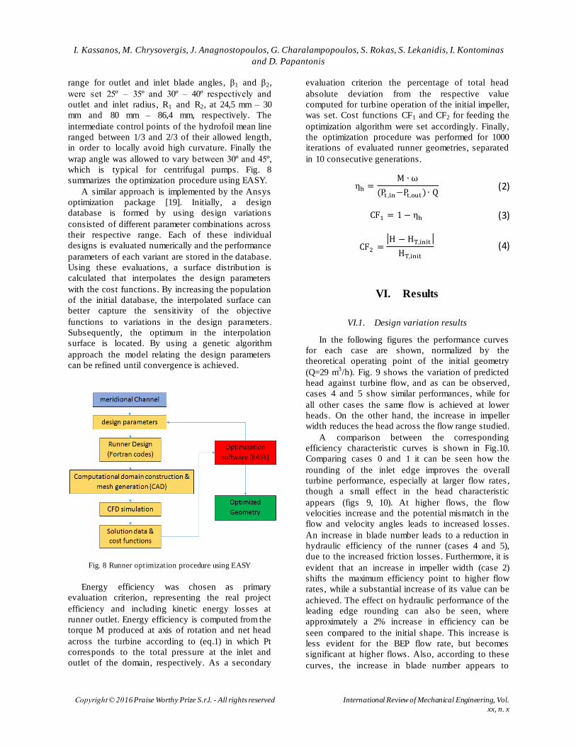
Fig. 8 Runner optimization procedure using EASY
Energy efficiency was chosen as primary
evaluation criterion, representing the real project
efficiency and including kinetic energy losses at
runner outlet. Energy efficiency is computed from the
torque M produced at axis of rotation and net head
across the turbine according to (eq.1) in which Pt
corresponds to the total pressure at the inlet and
outlet of the domain, respectively. As a secondary
evaluation criterion the percentage of total head
absolute deviation from the respective value
computed for turbine operation of the initial impeller,
was set. Cost functions CF1 and CF2 for feeding the
optimization algorithm were set accordingly. Finally,
the optimization procedure was performed for 1000
iterations of evaluated runner geometries, separated
in 10 consecutive generations.
ηh =Μ ∙ ω
(Pt ,in−Pt,out) ∙ Q (2)
CF1 = 1 − ηh (3)
CF2 =|H − HT,init |
HT,init
(4)
VI. Results
VI.1. Design variation results
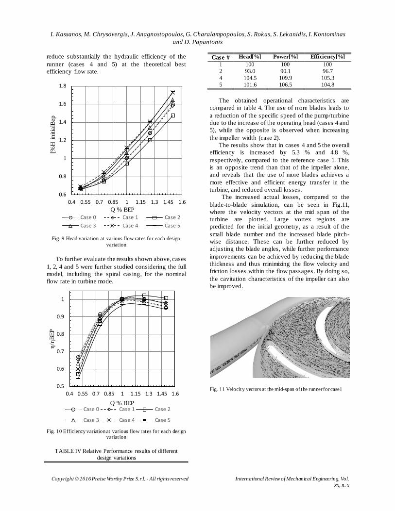
In the following figures the performance curves
for each case are shown, normalized by the
theoretical operating point of the initial geometry
(Q=29 m3/h). Fig. 9 shows the variation of predicted
head against turbine flow, and as can be observed,
cases 4 and 5 show similar performances, while for
all other cases the same flow is achieved at lower
heads. On the other hand, the increase in impeller
width reduces the head across the flow range studied.
A comparison between the corresponding
efficiency characteristic curves is shown in Fig.10.
Comparing cases 0 and 1 it can be seen how the
rounding of the inlet edge improves the overall
turbine performance, especially at larger flow rates ,
though a small effect in the head characteristic
appears (figs 9, 10). At higher flows, the flow
velocities increase and the potential mismatch in the
flow and velocity angles leads to increased losses.
An increase in blade number leads to a reduction in
hydraulic efficiency of the runner (cases 4 and 5),
due to the increased friction losses. Furthermore, it is
evident that an increase in impeller width (case 2)
shifts the maximum efficiency point to higher flow
rates, while a substantial increase of its value can be
achieved. The effect on hydraulic performance of the
leading edge rounding can also be seen, where
approximately a 2% increase in efficiency can be
seen compared to the initial shape. This increase is
less evident for the BEP flow rate, but becomes
significant at higher flows. Also, according to these
curves, the increase in blade number appears to
I. Kassanos, M. Chrysovergis, J. Anagnostopoulos, G. Charalampopoulos, S. Rokas, S. Lekanidis, I. Kontominas
and D. Papantonis
Copyright © 2016 Praise Worthy Prize S.r.l. - All rights reserved International Review of Mechanical Engineering, Vol.
xx, n. x
reduce substantially the hydraulic efficiency of the
runner (cases 4 and 5) at the theoretical best
efficiency flow rate.
Fig. 9 Head variation at various flow rates for each design
variation
To further evaluate the results shown above, cases
1, 2, 4 and 5 were further studied considering the full
model, including the spiral casing, for the nominal
flow rate in turbine mode.
Fig. 10 Efficiency variation at various flow rates for each design
variation
TABLE IV Relative Performance results of different
design variations
Case # Head[%] Power[%] Efficiency[%]
1 100 100 100
2 93.0 90.1 96.7
4 104.5 109.9 105.3
5 101.6 106.5 104.8
The obtained operational characteristics are
compared in table 4. The use of more blades leads to
a reduction of the specific speed of the pump/turbine
due to the increase of the operating head (cases 4 and
5), while the opposite is observed when increasing
the impeller width (case 2).
The results show that in cases 4 and 5 the overall
efficiency is increased by 5.3 % and 4.8 %,
respectively, compared to the reference case 1. This
is an opposite trend than that of the impeller alone,
and reveals that the use of more blades achieves a
more effective and efficient energy transfer in the
turbine, and reduced overall losses.
The increased actual losses, compared to the
blade-to-blade simulation, can be seen in Fig.11,
where the velocity vectors at the mid span of the
turbine are plotted. Large vortex regions are
predicted for the initial geometry, as a result of the
small blade number and the increased blade pitch-
wise distance. These can be further reduced by
adjusting the blade angles, while further performance
improvements can be achieved by reducing the blade
thickness and thus minimizing the flow velocity and
friction losses within the flow passages. By doing so,
the cavitation characteristics of the impeller can also
be improved.
Fig. 11 Velocity vectors at the mid-span of the runner for case1
0.6
0.8
1
1.2
1.4
1.6
1.8
0.4 0.55 0.7 0.85 1 1.15 1.3 1.45 1.6
[%H
in
itia
lBep
Q % BEP
Case 0 Case 1 Case 2
Case 3 Case 4 Case 5
0.5
0.6
0.7
0.8
0.9
1
0.4 0.55 0.7 0.85 1 1.15 1.3 1.45 1.6
η/η
BE
P
Q % BEP Case 0 Case 1 Case 2
Case 3 Case 4 Case 5
I. Kassanos, M. Chrysovergis, J. Anagnostopoulos, G. Charalampopoulos, S. Rokas, S. Lekanidis, I. Kontominas
and D. Papantonis
Copyright © 2016 Praise Worthy Prize S.r.l. - All rights reserved International Review of Mechanical Engineering, Vol.
xx, n. x
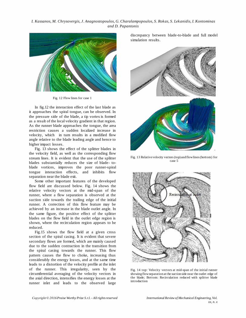
Fig. 12 Flow lines for case 1
In fig.12 the interaction effect of the last blade as
it approaches the spiral tongue, can be observed. In
the pressure side of the blade, a tip vortex is formed
as a result of the local velocity gradient in that region.
As the runner blade approaches the tongue, the area
restriction causes a sudden localized increase in
velocity, which in turn results in a modified flow
angle relative to the blade leading angle and hence to
higher impact losses.
Fig. 13 shows the effect of the splitter blades in
the velocity field, as well as the corresponding flow
stream lines. It is evident that the use of the splitter
blades substantially reduces the size of blade- to-
blade vortices, improves the poor runner-spiral
tongue interaction effects, and inhibits flow
separation near the blade exit.
Some other important features of the developed
flow field are discussed below. Fig. 14 shows the
relative velocity vectors at the mid-span of the
runner, where a flow separation is observed at the
suction side towards the trailing edge of the initial
runner. A correction of this flow feature may be
achieved by an increase in the blade outlet angle. In
the same figure, the positive effect of the splitter
blades on the flow field in the outlet edge region is
shown, where the recirculation region appears to be
reduced.
Fig.15 shows the flow field at a given cross
section of the spiral casing. It is evident that severe
secondary flows are formed, which are mainly caused
due to the sudden contraction in the transition from
the spiral casing towards the runner. This flow
pattern causes the flow to choke, increasing thus
considerably the energy losses, and at the same time
leads to a distortion of the velocity profile at the inlet
of the runner. This irregularity, seen by the
circumferential averaging of the velocity vectors in
the axial direction, intensifies the energy losses at the
runner inlet and leads to the observed large
discrepancy between blade-to-blade and full model
simulation results.
Fig. 13 Relative velocity vectors (top) and flow lines (bottom) for case 5
Fig. 14 top: Velocity vectors at mid-span of the initial runner
showing flow separation at the suction side near the outlet edge of the blade; Bottom: Recirculation reduced with splitter blade introduction
I. Kassanos, M. Chrysovergis, J. Anagnostopoulos, G. Charalampopoulos, S. Rokas, S. Lekanidis, I. Kontominas
and D. Papantonis
Copyright © 2016 Praise Worthy Prize S.r.l. - All rights reserved International Review of Mechanical Engineering, Vol.
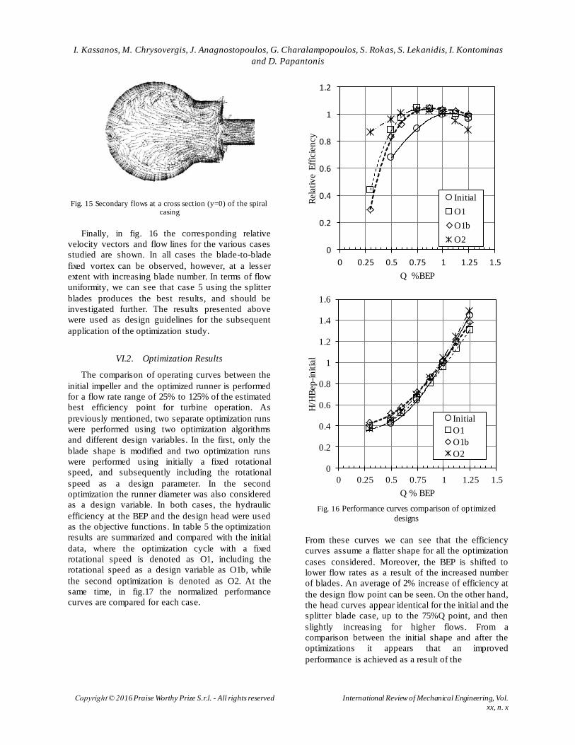
xx, n. x
Fig. 15 Secondary flows at a cross section (y=0) of the spiral casing
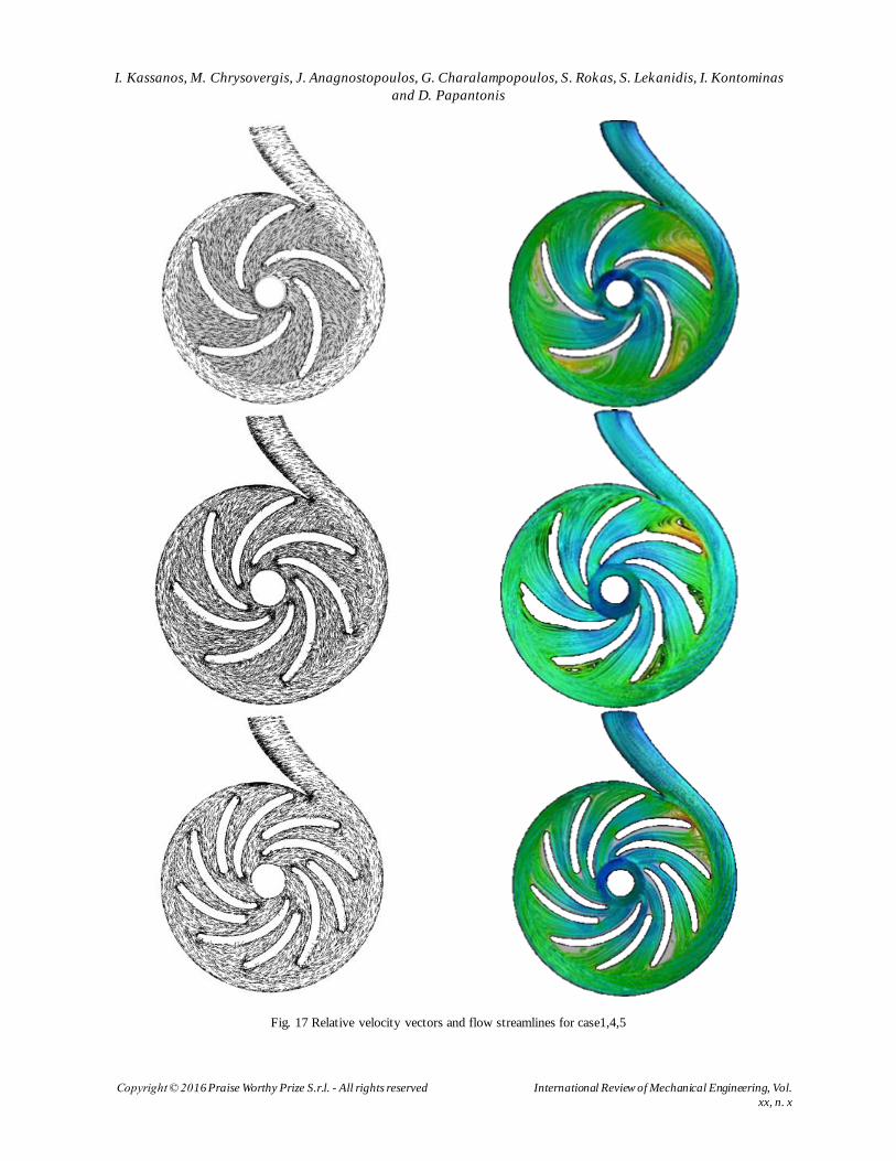
Finally, in fig. 16 the corresponding relative
velocity vectors and flow lines for the various cases
studied are shown. In all cases the blade-to-blade
fixed vortex can be observed, however, at a lesser
extent with increasing blade number. In terms of flow
uniformity, we can see that case 5 using the splitter
blades produces the best results, and should be
investigated further. The results presented above
were used as design guidelines for the subsequent
application of the optimization study.
VI.2. Optimization Results
The comparison of operating curves between the
initial impeller and the optimized runner is performed
for a flow rate range of 25% to 125% of the estimated
best efficiency point for turbine operation. As
previously mentioned, two separate optimization runs
were performed using two optimization algorithms
and different design variables. In the first, only the
blade shape is modified and two optimization runs
were performed using initially a fixed rotational
speed, and subsequently including the rotational
speed as a design parameter. In the second
optimization the runner diameter was also considered
as a design variable. In both cases, the hydraulic
efficiency at the BEP and the design head were used
as the objective functions. In table 5 the optimization
results are summarized and compared with the initial
data, where the optimization cycle with a fixed
rotational speed is denoted as O1, including the
rotational speed as a design variable as O1b, while
the second optimization is denoted as O2. At the
same time, in fig.17 the normalized performance
curves are compared for each case.
Fig. 16 Performance curves comparison of optimized
designs
From these curves we can see that the efficiency
curves assume a flatter shape for all the optimization
cases considered. Moreover, the BEP is shifted to
lower flow rates as a result of the increased number
of blades. An average of 2% increase of efficiency at
the design flow point can be seen. On the other hand,
the head curves appear identical for the initial and the
splitter blade case, up to the 75%Q point, and then
slightly increasing for higher flows. From a
comparison between the initial shape and after the
optimizations it appears that an improved
performance is achieved as a result of the
0
0.2
0.4
0.6
0.8
1
1.2
0 0.25 0.5 0.75 1 1.25 1.5
Rela
tiv
e E
ffic
ien
cy
Q %BEP
Initial
O1
O1b
O2
0
0.2
0.4
0.6
0.8
1
1.2
1.4
1.6
0 0.25 0.5 0.75 1 1.25 1.5
H/H
Bep
-in
itia
l
Q % BEP
Initial
O1
O1b
O2
I. Kassanos, M. Chrysovergis, J. Anagnostopoulos, G. Charalampopoulos, S. Rokas, S. Lekanidis, I. Kontominas
and D. Papantonis
Copyright © 2016 Praise Worthy Prize S.r.l. - All rights reserved International Review of Mechanical Engineering, Vol.
xx, n. x
Fig. 17 Relative velocity vectors and flow streamlines for case1,4,5
International Review of Mechanical Engineering (I.RE.M.E.), Vol. xx, n. x
Manuscript received January 2016, revised xxxxx 2016 Copyright © 2016 Praise Worthy Prize S.r.l. - All rights reserved
change in geometry, which better conforms to the design
flow conditions. The optimized geometries show an
improved performance across an extended operating
range showing a 2.3%-2.7 efficiency increase at the
design flow point (table 4) and up to a 4.4% increase at a
flow rate of 125%Q. In fig.17, O2 shows a better
performance variation for lower flow rates, while a
sudden drop in performance is observed for flow rates
higher than 110Q. Furthermore, it should be pointed out
that in all optimization cases even higher efficiencies
could be achieved for partial flow conditions.
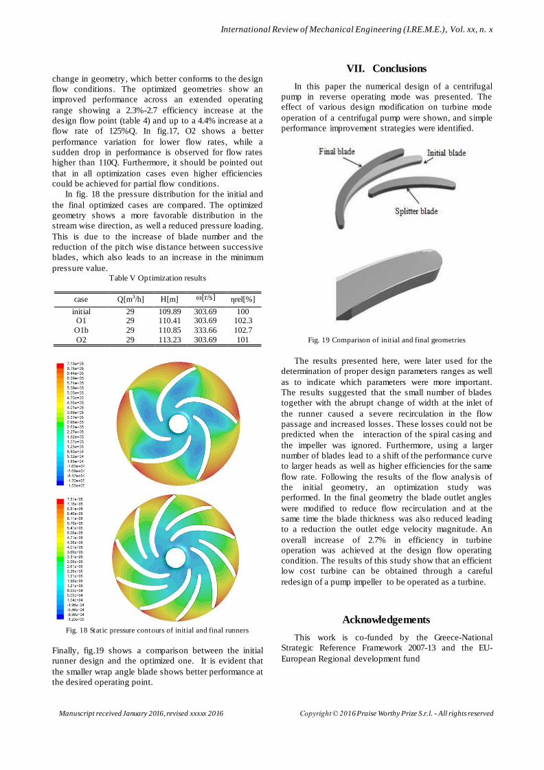
In fig. 18 the pressure distribution for the initial and
the final optimized cases are compared. The optimized
geometry shows a more favorable distribution in the
stream wise direction, as well a reduced pressure loading.
This is due to the increase of blade number and the
reduction of the pitch wise distance between successive
blades, which also leads to an increase in the minimum
pressure value. Table V Optimization results
case Q[m3/h] H[m] ω[r/s] ηrel[%]
initial 29 109.89 303.69 100 O1 29 110.41 303.69 102.3
O1b 29 110.85 333.66 102.7
O2 29 113.23 303.69 101
Fig. 18 Static pressure contours of initial and final runners
Finally, fig.19 shows a comparison between the initial
runner design and the optimized one. It is evident that
the smaller wrap angle blade shows better performance at
the desired operating point.
VII. Conclusions
In this paper the numerical design of a centrifugal
pump in reverse operating mode was presented. The
effect of various design modification on turbine mode
operation of a centrifugal pump were shown, and simple
performance improvement strategies were identified.
Fig. 19 Comparison of initial and final geometries
The results presented here, were later used for the
determination of proper design parameters ranges as well
as to indicate which parameters were more important.
The results suggested that the small number of blades
together with the abrupt change of width at the inlet of
the runner caused a severe recirculation in the flow
passage and increased losses. These losses could not be
predicted when the interaction of the spiral casing and
the impeller was ignored. Furthermore, using a larger
number of blades lead to a shift of the performance curve
to larger heads as well as higher efficiencies for the same
flow rate. Following the results of the flow analysis of
the initial geometry, an optimization study was
performed. In the final geometry the blade outlet angles
were modified to reduce flow recirculation and at the
same time the blade thickness was also reduced leading
to a reduction the outlet edge velocity magnitude. An
overall increase of 2.7% in efficiency in turbine
operation was achieved at the design flow operating
condition. The results of this study show that an efficient
low cost turbine can be obtained through a careful
redesign of a pump impeller to be operated as a turbine.
Acknowledgements
This work is co-funded by the Greece-National
Strategic Reference Framework 2007-13 and the EU-
European Regional development fund

I. Kassanos, M. Chrysovergis, J. Anagnostopoulos, G. Charalampopoulos, S. Rokas, S. Lekanidis, I. Kontominas and D.
Papantonis
Copyright © 2016 Praise Worthy Prize S.r.l. - All rights reserved International Review of Mechanical Engineering, Vol. xx, n. x
References.
[1] A. Williams, “The turbine performance of centrifugal pumps: a comparison of prediction methods”, Proceedings of the Institution of Mechanical Engineers, Part A: Journal of Power and Energy, 1994, pp. 59-66.
[2] A. Willimas, Pumps as turbines for low cost micro hydro power,
Renewable Energy, Vol. 9, pp. 1227-1234, 1996.
[3] M. Arriaga, Pump as turbine - A pico hydro alternative in Lao Peoples’s Democratic Republic, Renewable Energy, Vol. 35, pp. 1109-1115, 2010
[4] S. Jain, A. Swankar, K. Motwani, R. Patel, Effects of impeller
diameter and rotational speed on performance of pump running in turbine mode, Energy Conversion and Management, Vol. 89,
pp. 808-824, 2015. [5] S. Yang, S. Derakhshan, F. Kong, Theoretical, numerical and
experimental prediction of pump as turbine performance,
Renewable energy, Vol. 48, pp. 507-513, 2012. [6] S. Yang, F. Kong, W. Jiang, X. Qu, Effects of impeller trimming
influencing pump as turbine, Computers & Fluids,Vol. 67, pp.
72-78, 2012. [7] D. Giosio, A. Henderson, J. Walker, P. Brandner, J. Sargison, P.
Gautam, Design and performance evaluation of a pump-as-turbine micro hydro test facility with incorporated inlet flow control, Renewable Energy, Vol. 78, pp. 1-6, 2015.
[8] M. Golcu, Yasar Pancar, Y. Sekmen, Energy saving in a deep well pump with splitter blade, Energy conversion and Management, Vol. 47, pp. 638-651, 2006.
[9] Hou Y. Research on the length ratio of splitter blades for Ultra High Head Francis runners, Procedia Engineering ,Vol. 31, pp. 92-96, 2012.
[10] L Meng, S P Zhang, L J Zhou, Z W Wang. Study on the Pressure Pulsation inside Runner with Splitter Blades in Ultra-High Head Turbine, Proc. of the 27th IAHR Symposium on Hydraulic machinery and systems, Montreal, 2014
[11] O. Antonsen, T . Nielsen, O. Dahlhaug, J T Billdal. Pressure
Pulses in Francis Turbines vs. Guide Vane Design. Proc of the
23th IAHR Symposium on Hydraulic machinery and system s, Yokohama, 2006.
[12] Y L Zhang, S Q Yuan, J F Zhabg, Y N Feng, J X Lu, Numerical
investigation of the effects of splitter blades on the cavitation performance of a centrifugal pump, Proc. of the 27th IAHR Symposium on Hydrulic machinery and systems, Montreal, 2014.
[13] S C Li. Cavitation of Hydraulic Machinery (Imperial College Press, 2000).
[14] S. Miyauchi, B. Zhu, X. Luo, B. Piao, H. Matsumato, M. Sano,
N. Kassai, Optimization and Inverse Design of Pump Impeller, 26th IAHR Symposium on Hydraulic Macinery and Systems, Beijing, 2012
[15] B. Zhu, X.Whang, L. Tan, D. Zhou, Y. Zhao, S. Cao,
Optimization design of a reversible pump-turbine runner with high efficiency and stability, Renewable energy, Vol. 81, pp.
366-376, 2015 [16] W.C. Schleicher, A. Oztekin, Hydraulic design and optimization
of a modular pump-turbine runner, Energy Conversion and Management, Vol. 93, pp. 388-398, 2015
[17] ANSYS, Inc. ANSYS FLUENT Solver Theory Guide, Release
15. 2013 [online] Available at: https://support.ansys.com/portal/site/AnsysCustomerPortal/templ
ate.fss?file=%2Fprod_docu%2F15.0%2FANSYS+Fluent+Users+Guide.pdf
[18] Giannakoglou, K.C., Design of optimal aerodynamic shapes
using stochastic optimization methods and computational
intelligence, Progress in Aerospace Science, Vol. 38, pp. 43-76,2002.
[19] ANSYS, Inc. Design Exploration User’s Guide, Release 15.
2013 [online] Available at: https://support.ansys.com/portal/site/AnsysCustomerPortal/template.fss?file=%2Fprod_docu%2F15.0%2FDesign+Exploration+Users+Guide.pdf
Authors’ information 1National Technical University of Athens, Heroon Polytechneiou 9,
Zografou, 15780, Greece 2Drakos-Polemis Pumps, Kolokotroni 16, Kryoneri, Greece
I.D. Kassanos graduated in Mechanical Engineering from the National Technical University of Athens, Greece, and received his
MSc degree in Energy Conversion and Management from the University of Nottingham, UK. He is currently a PhD
candidate in the Laboratory of Hydraulic Turbomachines. His research interests include
the design and flow simulation of hydraulic machinery, study of cavitation and unsteady phenomena in hydro-turbines, and laboratory
testing of hydraulic machinery.
M.M. Chrysovergis graduated in Mechanical Engineering from the National Technical
University of Athens, Greece. He is currently a PhD candidate in the Laboratory of Hydraulic Turbomachines and also a student in the Interdisciplinary Post - Graduate Programme
“Environment and Development” of the same University. His undergoing PhD Thesis is focused on parametric design, flow simulation
and numerical optimization of Pumps as Turbines [PAT].
J.S. Anagnostopoulos graduated in Mechanical Engineering from the National
Technical University of Athens, Greece, and received his Ph.D. in Computational Fluid Mechanics from the same University. He worked for several years as post -doctoral
researcher in the NTUA and as R&T consultant in the private sector where he has
been involved in feasibility studies for various industrial innovations.
He has participated in more than 40 research projects, and has more than 90 scientific publications in international journals and conferences. Also, he has developed a number of advanced computer codes for the simulation of various fluid mechanisms in industrial applications, as
well as for modeling and optimization of hydroelectric and hybrid energy systems with pumped storage. He is Associate Professor in Hydraulic Turbomachines at the School of Mechanical Engineering, NTUA, Greece and his current research activities include flow
simulation and hydrodynamic design in pumps and hydroturbines.
George Charalabopoulos, Master of Science in Energy and the Build Environment
“Cranfield institute of technology ( U.K.)”. He participated in E.U – National “ NSRF 2007 – 2013” Project: “Study and optimum design of
a centrifugal pump for efficient operation as turbine in hydroelectric systems for building, industrial and agricultural use, latest
publication is at the ICNAM 2015 international conference: Ioannis
Kassanos, Marios Chrysovergis, John Anagnostopoulos, Dimitris Papantonis and George Charalampopoulos “Numerical performance
I. Kassanos, M. Chrysovergis, J. Anagnostopoulos, G. Charalampopoulos, S. Rokas, S. Lekanidis, I. Kontominas and D.
Papantonis
Copyright © 2016 Praise Worthy Prize S.r.l. - All rights reserved International Review of Mechanical Engineering, Vol. xx, n. x
evaluation of design modifications on a centrifugal pump impeller running in reverse mode”. He was an associated lecturer of fluid
dynamic Ι and ΙΙ and Hydrodynamic machines, laboratory of the Technological Institute of Piraeus. He was the lecturer of two seminar: "Harnessing renewable energy at local level ", recommendation subject:
" Calculating energy efficiency of wind turbines. Also he was a leader of the seminar organizing: IEM Studies research and environmental management projects. Today he is the head of the technical department of DRAKOS – POLEMIS pumps industry.
Stamelos Rokas Graduated as an Electrical Engineer from the Technical Institute of Chalkida, Greece and received a Msc for the
mechanical department – Heriot Watt University Edinburgh with postgraduate study: Power Plant Siting Using Geographical Information System as Decision Support Tool
for the Island of Syros. He participated in E.U – National “ NSRF 2007 – 2013” of the Project: “Study and optimum design of a centrifugal pump for efficient operation as turbine in
hydroelectric systems for building, industrial and agricultural use. Latest publication: RES‐Based Power Plants Siting Using Geographical Information Systems, International Conference on Clean Electrical
Power Renewable Energy Resources Impact, Ischia Italy, 2011. Today he is working as an engineer of DRAKOS – POLEMIS pumps industry in the research electrical department and in the testing laboratory.
Stavros Lekanidis Graduated as an Electrical Engineer from the Technical Engineer Department of the Technical Highest School Of Heraklion, Greece. He also received
certification of education for “Project Management” from the National and Kapodistrian University of Athens. He participated in E.U – National “NSRF 2007 –
2013” as Head of the Project: “Study and optimum design of a centrifugal pump for efficient operation as turbine in hydroelectric systems for building, industrial and agricultural use. He
has also finished a study with subject “ Amplifiers for low frequencies “ and has the following Seminar certifications: “Modern Production Techniques ”, “Study and Installation of Photovoltaic systems ”, “ Study of Natural Gas installations ”. Today he is the head of the
factory and production of DRAKOS – POLEMIS pumps industry, as well as head of the technical research electrical department.
Ioannis Kontominas Graduated in Mechanical Engineering from the National technical University of Athens, Greece and received his second Master in control systems
at 2003 and he is a member of the Technical Chamber of Greece. Today he is working at DRAKOS – POLEMIS as engineering
manager concerning special applications, and he is member of the EU-National ”NSRF 2007-2013” Project “Study and optimum design of a centrifugal pump for efficient operation as turbine in hydroelectric systems for building, industrial and agricultural
use”.
D.E. Papantonis graduated in Mechanical and Electrical Engineering from the National
Technical University of Athens, Greece, and received his Docteur-Ingenieur in Fluid Mechanics from the Ecole d’ Hydraulique, Institut National Polytechnique de Toulouse.
He is expert in design and operation of hydraulic machinery and installations,
including transient phenomena and water hammer. He has been
involved in feasibility studies for several small hydro projects in Greece, as well as in many research projects for hydroelectric, hydraulic and pumping installations, funded by national and private entities and by the EU, and has numerous scientific publications in
international journals and conference proceedings. He is Professor and Director of the Hydraulic Turbomachines Lab. at the School of
Mechanical Engineering, NTUA, Greece, and his current research activities include centrifugal pumps and hydroturbines design,
manufacture and experimental testing.