Optimization of Centrifugal Pump Impeller Outlet Vane ... · Keywords: Centrifugal Pump,...
5
International Journal of Current Engineering and Technology E-ISSN 2277 – 4106, P-ISSN 2347 – 5161 ©2015 INPRESSCO ® , All Rights Reserved Available at http://inpressco.com/category/ijcet Research Article 1091| International Journal of Current Engineering and Technology, Vol.5, No.2 (April 2015) Optimization of Centrifugal Pump Impeller Outlet Vane Angle by using Modal Analysis Kotakar Sandeep Gulabrao †* and D.S. Khedekar † † Department of Mechanical Engineering, JNEC, Aurangabad, India (MH), India Accepted 07 April 2015, Available online 12 April 2015, Vol.5, No.2 (April 2015) Abstract A number of variety of centrifugal pump have been constructed and used in many different applications in domestics, Agricultural, industry and other technical sectors. Due to the great number of free geometric parameters, their design and performance prediction process is still a difficult task, mainly the effect of which cannot be directly evaluated. The significant cost and time of the trial-and-error process by constructing and testing physical prototypes is always undesirable. For this reason taking one analysis parameter, design the pump result check by software and finally check the result by experimental method. Analysis is currently being used in the design and construction stage of various pump types, the use of which reduces significantly the new pump development time and costs. The numerical simulation can provide quite accurate information on the fluid behavior in the machine, and thus helps the engineer to obtain a thorough performance evaluation of a particular design. Performance study predicts the performance of pump impellers and helps us rapidly to establish the efficiency of the pump over various operating conditions. Keywords: Centrifugal Pump, Centrifugal Impeller, Performance Curves, ANSYS 1. Introduction 1 Centrifugal pump is a machine that imparts energy to a fluid. This energy can cause a liquid to flow or rise to a higher level. Centrifugal pump is an extremely simple machine which consists of two basic parts: The rotary element or impeller and the stationary element or casing. The centrifugal pumps are widely used in the world because the pump is robust, effective and inexpensive to produce. Centrifugal pumps are more economical to own, operate and maintain than other types of pumps. Pumps operate via many energy sources, including manual operation, electricity, engines, or wind power, come in many sizes, from microscopic for use in medical applications to large industrial pumps. Mechanical pumps serve in a wide range of applications such as pumping water from wells, aquarium filtering, pond filtering and aeration, in the car industry for water-cooling and fuel injection etc. Effect of vane angle change in systems of impeller pumps have been studied by theoretically, using design software and experimentally. Different design solutions have been considered for single-stage and multi stage pumps. Some of them were patented, for example, (Martsinkovsky et al., 1995; Kubota, 1999) and (Chiba et al., 2007), respectively. It can be assumed that hydrostatic and hydrodynamic forces occurring in *Corresponding author: Kotakar Sandeep Gulabrao the longitudinal and lateral of the system ensure the right position of the impeller relative to the pump casing and stable operation of the pump. The objective of this study was to analyze an impeller of a single- stage pump directly connected with the vane angle change in systems with specially designed Impeller. The balancing device acts as both the longitudinally and laterally of the single-stage centrifugal pump. The paper focuses on the static analysis of the system and modal analysis of pump systems 2. Impeller Design Impellers directly connected with a balancing device were first patented in the 1990s, for instance (Korczak et al., 2005; Pavlenko, 2008). The distinctive feature of the design of the single-stage pump impeller described in the patent (Martsinkovsky et al., 1995) is the lack of a classic drive shaft linked to the rolling element bearings. Instead of a bearing node, there are longitudinal and lateral seal clearances of the impeller and the balancing device. The hydrodynamic forces and moments generated in these clearances position the impeller relative to the pump casing. The impeller is driven by a flexible shaft with a relatively small diameter. The small diameter of the shaft results from the torque passed from the motor via a ball joint to the impeller.
Transcript of Optimization of Centrifugal Pump Impeller Outlet Vane ... · Keywords: Centrifugal Pump,...
International Journal of Current Engineering and Technology E-ISSN 2277 – 4106, P-ISSN 2347 – 5161 ©2015 INPRESSCO®, All Rights Reserved Available at http://inpressco.com/category/ijcet
Research Article
1091| International Journal of Current Engineering and Technology, Vol.5, No.2 (April 2015)
Optimization of Centrifugal Pump Impeller Outlet Vane Angle by using Modal Analysis
Kotakar Sandeep Gulabrao†* and D.S. Khedekar† †Department of Mechanical Engineering, JNEC, Aurangabad, India (MH), India
Accepted 07 April 2015, Available online 12 April 2015, Vol.5, No.2 (April 2015)
Abstract A number of variety of centrifugal pump have been constructed and used in many different applications in domestics, Agricultural, industry and other technical sectors. Due to the great number of free geometric parameters, their design and performance prediction process is still a difficult task, mainly the effect of which cannot be directly evaluated. The significant cost and time of the trial-and-error process by constructing and testing physical prototypes is always undesirable. For this reason taking one analysis parameter, design the pump result check by software and finally check the result by experimental method. Analysis is currently being used in the design and construction stage of various pump types, the use of which reduces significantly the new pump development time and costs. The numerical simulation can provide quite accurate information on the fluid behavior in the machine, and thus helps the engineer to obtain a thorough performance evaluation of a particular design. Performance study predicts the performance of pump impellers and helps us rapidly to establish the efficiency of the pump over various operating conditions. Keywords: Centrifugal Pump, Centrifugal Impeller, Performance Curves, ANSYS 1. Introduction
1 Centrifugal pump is a machine that imparts energy to a fluid. This energy can cause a liquid to flow or rise to a higher level. Centrifugal pump is an extremely simple machine which consists of two basic parts: The rotary element or impeller and the stationary element or casing. The centrifugal pumps are widely used in the world because the pump is robust, effective and inexpensive to produce. Centrifugal pumps are more economical to own, operate and maintain than other types of pumps. Pumps operate via many energy sources, including manual operation, electricity, engines, or wind power, come in many sizes, from microscopic for use in medical applications to large industrial pumps. Mechanical pumps serve in a wide range of applications such as pumping water from wells, aquarium filtering, pond filtering and aeration, in the car industry for water-cooling and fuel injection etc. Effect of vane angle change in systems of impeller pumps have been studied by theoretically, using design software and experimentally. Different design solutions have been considered for single-stage and multi stage pumps. Some of them were patented, for example, (Martsinkovsky et al., 1995; Kubota, 1999) and (Chiba et al., 2007), respectively. It can be assumed that hydrostatic and hydrodynamic forces occurring in *Corresponding author: Kotakar Sandeep Gulabrao
the longitudinal and lateral of the system ensure the right position of the impeller relative to the pump casing and stable operation of the pump. The objective of this study was to analyze an impeller of a single-stage pump directly connected with the vane angle change in systems with specially designed Impeller. The balancing device acts as both the longitudinally and laterally of the single-stage centrifugal pump. The paper focuses on the static analysis of the system and modal analysis of pump systems
2. Impeller Design
Impellers directly connected with a balancing device
were first patented in the 1990s, for instance (Korczak
et al., 2005; Pavlenko, 2008). The distinctive feature of
the design of the single-stage pump impeller described
in the patent (Martsinkovsky et al., 1995) is the lack of
a classic drive shaft linked to the rolling element
bearings. Instead of a bearing node, there are
longitudinal and lateral seal clearances of the impeller
and the balancing device. The hydrodynamic forces
and moments generated in these clearances position
the impeller relative to the pump casing. The impeller
is driven by a flexible shaft with a relatively small
diameter. The small diameter of the shaft results from
the torque passed from the motor via a ball joint to the
impeller.
Kotakar Sandeep Gulabrao et al Optimization of Centrifugal Pump Impeller Outlet Vane Angle by using Modal Analysis
1092| International Journal of Current Engineering and Technology, Vol.5, No.2 (April 2015)
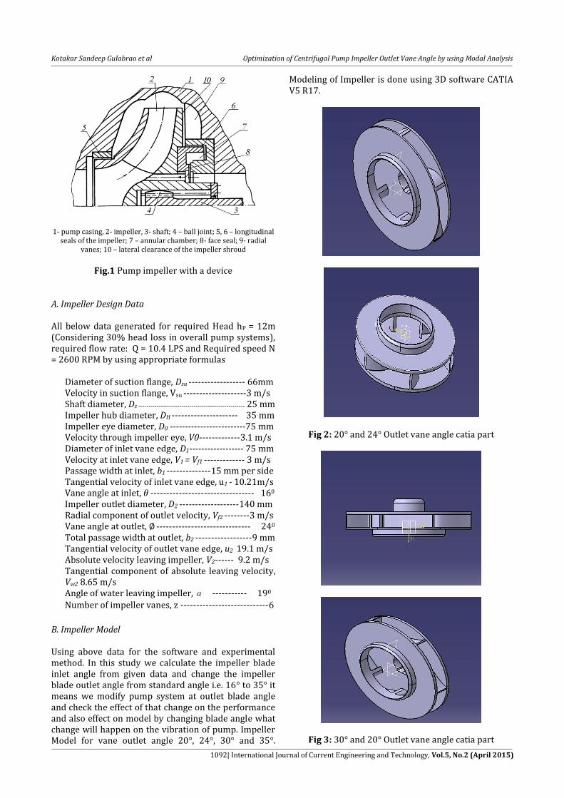
1- pump casing, 2- impeller, 3- shaft; 4 – ball joint; 5, 6 – longitudinal
seals of the impeller; 7 – annular chamber; 8- face seal; 9- radial vanes; 10 – lateral clearance of the impeller shroud
Fig.1 Pump impeller with a device
A. Impeller Design Data All below data generated for required Head hP = 12m (Considering 30% head loss in overall pump systems), required flow rate: Q = 10.4 LPS and Required speed N = 2600 RPM by using appropriate formulas Diameter of suction flange, Dsu ------------------ 66mm Velocity in suction flange, Vsu --------------------3 m/s Shaft diameter, Ds ---------------------------------------------------- 25 mm Impeller hub diameter, DH --------------------- 35 mm Impeller eye diameter, D0 -------------------------75 mm Velocity through impeller eye, V0-------------3.1 m/s Diameter of inlet vane edge, D1------------------ 75 mm Velocity at inlet vane edge, V1 = Vf1 ------------- 3 m/s Passage width at inlet, b1 --------------15 mm per side Tangential velocity of inlet vane edge, u1 - 10.21m/s Vane angle at inlet, --------------------------------- 160 Impeller outlet diameter, D2 -------------------140 mm Radial component of outlet velocity, Vf2 --------3 m/s Vane angle at outlet, ------------------------------ 240 Total passage width at outlet, b2 ------------------9 mm Tangential velocity of outlet vane edge, u2 19.1 m/s Absolute velocity leaving impeller, V2------ 9.2 m/s Tangential component of absolute leaving velocity, Vw2 8.65 m/s Angle of water leaving impeller, ----------- 190
Number of impeller vanes, z ----------------------------6
B. Impeller Model Using above data for the software and experimental method. In this study we calculate the impeller blade inlet angle from given data and change the impeller blade outlet angle from standard angle i.e. 16 to 35 it means we modify pump system at outlet blade angle and check the effect of that change on the performance and also effect on model by changing blade angle what change will happen on the vibration of pump. Impeller Model for vane outlet angle 20 , 24 , 30 and 35 .
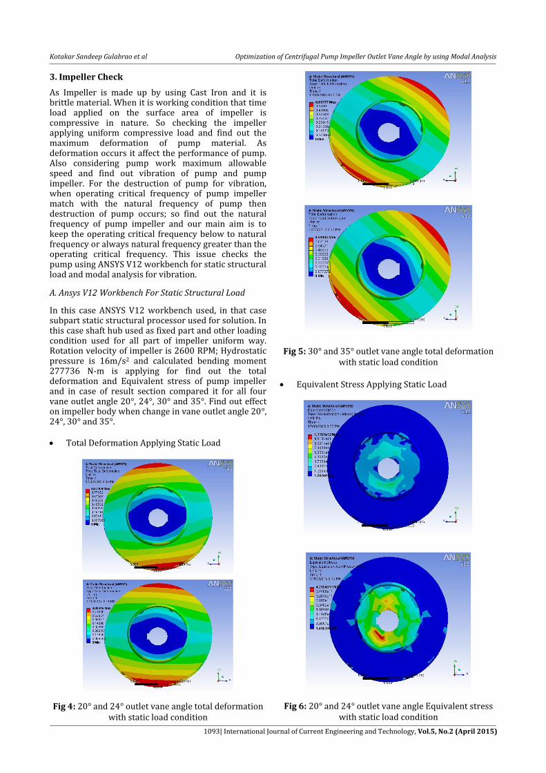
Modeling of Impeller is done using 3D software CATIA V5 R17.
Fig 2: 20 and 24 Outlet vane angle catia part
Fig 3: 30 and 20 Outlet vane angle catia part
Kotakar Sandeep Gulabrao et al Optimization of Centrifugal Pump Impeller Outlet Vane Angle by using Modal Analysis
1093| International Journal of Current Engineering and Technology, Vol.5, No.2 (April 2015)
3. Impeller Check
As Impeller is made up by using Cast Iron and it is brittle material. When it is working condition that time load applied on the surface area of impeller is compressive in nature. So checking the impeller applying uniform compressive load and find out the maximum deformation of pump material. As deformation occurs it affect the performance of pump. Also considering pump work maximum allowable speed and find out vibration of pump and pump impeller. For the destruction of pump for vibration, when operating critical frequency of pump impeller match with the natural frequency of pump then destruction of pump occurs; so find out the natural frequency of pump impeller and our main aim is to keep the operating critical frequency below to natural frequency or always natural frequency greater than the operating critical frequency. This issue checks the pump using ANSYS V12 workbench for static structural load and modal analysis for vibration.
A. Ansys V12 Workbench For Static Structural Load
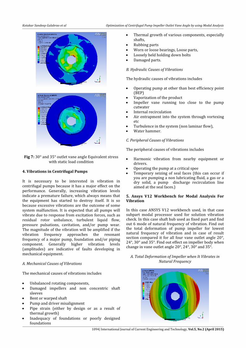
In this case ANSYS V12 workbench used, in that case subpart static structural processor used for solution. In this case shaft hub used as fixed part and other loading condition used for all part of impeller uniform way. Rotation velocity of impeller is 2600 RPM; Hydrostatic pressure is 16m/s2 and calculated bending moment 277736 N-m is applying for find out the total deformation and Equivalent stress of pump impeller and in case of result section compared it for all four vane outlet angle 20 , 24 , 30 and 35 . Find out effect on impeller body when change in vane outlet angle 20 , 24 , 30 and 35 .
Total Deformation Applying Static Load
Fig 4: 20 and 24 outlet vane angle total deformation with static load condition
Fig 5: 30 and 35 outlet vane angle total deformation
with static load condition
Equivalent Stress Applying Static Load
Fig 6: 20 and 24 outlet vane angle Equivalent stress with static load condition
Kotakar Sandeep Gulabrao et al Optimization of Centrifugal Pump Impeller Outlet Vane Angle by using Modal Analysis
1094| International Journal of Current Engineering and Technology, Vol.5, No.2 (April 2015)
Fig 7: 30 and 35 outlet vane angle Equivalent stress with static load condition
4. Vibrations in Centrifugal Pumps It is necessary to be interested in vibration in centrifugal pumps because it has a major effect on the performance. Generally, increasing vibration levels indicate a premature failure, which always means that the equipment has started to destroy itself. It is so because excessive vibrations are the outcome of some system malfunction. It is expected that all pumps will vibrate due to response from excitation forces, such as residual rotor unbalance, turbulent liquid flow, pressure pulsations, cavitation, and/or pump wear. The magnitude of the vibration will be amplified if the vibration frequency approaches the resonant frequency of a major pump, foundation and/or piping component. Generally higher vibration levels (amplitudes) are indicative of faults developing in mechanical equipment. A. Mechanical Causes of Vibrations The mechanical causes of vibrations includes Unbalanced rotating components, Damaged impellers and non concentric shaft
sleeves Bent or warped shaft Pump and driver misalignment Pipe strain (either by design or as a result of
thermal growth) Inadequacy of foundations or poorly designed
foundations
Thermal growth of various components, especially shafts,
Rubbing parts Worn or loose bearings, Loose parts, Loosely held holding down bolts Damaged parts. B. Hydraulic Causes of Vibrations The hydraulic causes of vibrations includes Operating pump at other than best efficiency point
(BEP) Vaporization of the product Impeller vane running too close to the pump
cutwater Internal recirculation Air entrapment into the system through vortexing
etc Turbulence in the system (non laminar flow), Water hammer. C. Peripheral Causes of Vibrations The peripheral causes of vibrations includes Harmonic vibration from nearby equipment or
drivers. Operating the pump at a critical spee Temporary seizing of seal faces (this can occur if
you are pumping a non lubricating fluid, a gas or a dry solid, a pump discharge recirculation line aimed at the seal faces.)
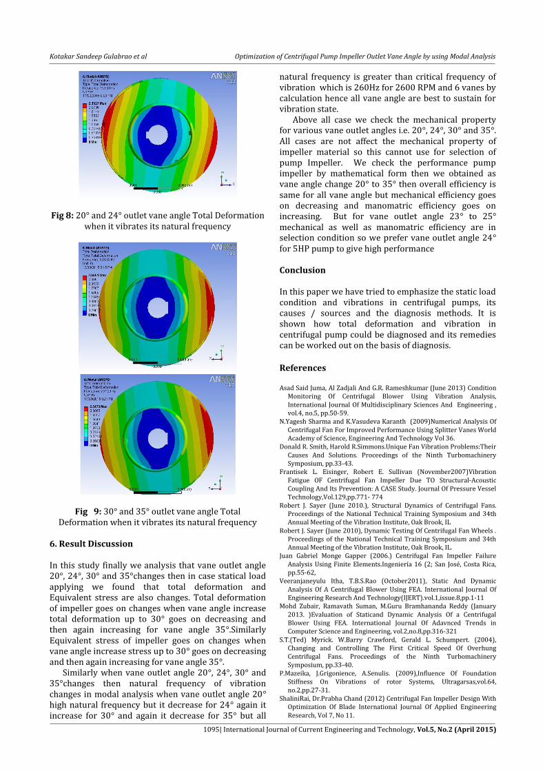
5. Ansys V12 Workbench for Modal Analysis For Vibration In this case ANSYS V12 workbench used, in that case subpart modal processor used for solution vibration check. In this case shaft hub used as fixed part and find out 6 mode of natural frequency of vibration. Find out the total deformation of pump impeller for lowest natural frequency of vibration and in case of result section compared it for all four vane outlet angle 20 , 24 , 30 and 35 . Find out effect on impeller body when change in vane outlet angle 20 , 24 , 30 and 35 .
A. Total Deformation of Impeller when It Vibrates in Natural Frequency
Kotakar Sandeep Gulabrao et al Optimization of Centrifugal Pump Impeller Outlet Vane Angle by using Modal Analysis
1095| International Journal of Current Engineering and Technology, Vol.5, No.2 (April 2015)
Fig 8: 20 and 24 outlet vane angle Total Deformation when it vibrates its natural frequency
Fig 9: 30 and 35 outlet vane angle Total Deformation when it vibrates its natural frequency
6. Result Discussion In this study finally we analysis that vane outlet angle 20 , 24 , 30 and 35 changes then in case statical load applying we found that total deformation and Equivalent stress are also changes. Total deformation of impeller goes on changes when vane angle increase total deformation up to 30 goes on decreasing and then again increasing for vane angle 35 .Similarly Equivalent stress of impeller goes on changes when vane angle increase stress up to 30 goes on decreasing and then again increasing for vane angle 35 . Similarly when vane outlet angle 20 , 24 , 30 and 35 changes then natural frequency of vibration changes in modal analysis when vane outlet angle 20 high natural frequency but it decrease for 24 again it increase for 30 and again it decrease for 35 but all
natural frequency is greater than critical frequency of vibration which is 260Hz for 2600 RPM and 6 vanes by calculation hence all vane angle are best to sustain for vibration state. Above all case we check the mechanical property for various vane outlet angles i.e. 20 , 24 , 30 and 35 . All cases are not affect the mechanical property of impeller material so this cannot use for selection of pump Impeller. We check the performance pump impeller by mathematical form then we obtained as vane angle change 20 to 35 then overall efficiency is same for all vane angle but mechanical efficiency goes on decreasing and manomatric efficiency goes on increasing. But for vane outlet angle 23 to 25 mechanical as well as manomatric efficiency are in selection condition so we prefer vane outlet angle 24 for 5HP pump to give high performance Conclusion In this paper we have tried to emphasize the static load condition and vibrations in centrifugal pumps, its causes / sources and the diagnosis methods. It is shown how total deformation and vibration in centrifugal pump could be diagnosed and its remedies can be worked out on the basis of diagnosis.
References Asad Said Juma, Al Zadjali And G.R. Rameshkumar (June 2013) Condition
Monitoring Of Centrifugal Blower Using Vibration Analysis, International Journal Of Multidisciplinary Sciences And Engineering , vol.4, no.5, pp.50-59.
N.Yagesh Sharma and K.Vasudeva Karanth (2009)Numerical Analysis Of Centrifugal Fan For Improved Performance Using Splitter Vanes World Academy of Science, Engineering And Technology Vol 36.
Donald R. Smith, Harold R.Simmons.Unique Fan Vibration Problems:Their Causes And Solutions. Proceedings of the Ninth Turbomachinery Symposium, pp.33-43.
Frantisek L. Eisinger, Robert E. Sullivan (November2007)Vibration Fatigue OF Centrifugal Fan Impeller Due TO Structural-Acoustic Coupling And Its Prevention: A CASE Study. Journal Of Pressure Vessel Technology,Vol.129,pp.771- 774
Robert J. Sayer (June 2010.), Structural Dynamics of Centrifugal Fans. Proceedings of the National Technical Training Symposium and 34th Annual Meeting of the Vibration Institute, Oak Brook, IL
Robert J. Sayer (June 2010), Dynamic Testing Of Centrifugal Fan Wheels . Proceedings of the National Technical Training Symposium and 34th Annual Meeting of the Vibration Institute, Oak Brook, IL.
Juan Gabriel Monge Gapper (2006.) Centrifugal Fan Impeller Failure Analysis Using Finite Elements.Ingeniería 16 (2; San José, Costa Rica, pp.55-62,
Veeranjaneyulu Itha, T.B.S.Rao (October2011), Static And Dynamic Analysis Of A Centrifugal Blower Using FEA. International Journal Of Engineering Research And Technology(IJERT).vol.1,issue.8,pp.1-11
Mohd Zubair, Ramavath Suman, M.Guru Bramhananda Reddy (January 2013. )Evaluation of Staticand Dynamic Analysis Of a Centrifugal Blower Using FEA. International Journal Of Adavnced Trends in Computer Science and Engineering, vol.2,no.8,pp.316-321
S.T.(Ted) Myrick. W.Barry Crawford, Gerald L. Schumpert. (2004), Changing and Controlling The First Critical Speed Of Overhung Centrifugal Fans. Proceedings of the Ninth Turbomachinery Symposium, pp.33-40.
P.Mazeika, J.Grigonience, A.Senulis. (2009),Influence Of Foundation Stiffness On Vibrations of rotor Systems, Ultragarsas,vol.64, no.2,pp.27-31.
ShaliniRai, Dr.Prabha Chand (2012) Centrifugal Fan Impeller Design With Optimization Of Blade International Journal Of Applied Engineering Research, Vol 7, No 11.