DC Dual Inlet Centrifugal Blowers · 2013-02-27 · Centrifugal Blowers SINGLE and DUAL INLET...
23
DC Dual Inlet Centrifugal Blowers
Transcript of DC Dual Inlet Centrifugal Blowers · 2013-02-27 · Centrifugal Blowers SINGLE and DUAL INLET...

DC Dual InletCentrifugal Blowers

Curve Ref. Rota- CFM Wgt. Temp.
Number Part Number Volts Watts Flange tion* @ 0" dBA (lbs.) Max. °C
1 D3G133-AB31-06 24 40 Yes R 285 52 6.5 50
2 D3G133-DB05-05 48 34 No R 335 54 6.5 50
3 D1G133-DC17-09 48 115 No R 656 60 7.0 50NOTE: Wiring connection: Red = +; Blue = —; Speed control by voltage typical range: +15% and – 30%.
*Rotation, as viewed from side opposite lead exit: R = clockwise; L = counter-clockwise
285 to 656 CFM Brushless DCDual Inlet Centrifugal Blowers
Dimensions – [ inches (mm)]Blower Type A B C D E F G H I J
D3G133-AB 6.73 7.09 3.46 3.11 10.0 9.37 4.25 2.91 8.46 2.72(171) (180) (88) (79) (254) (238) (108) (74) (215) (69)
D3G133-DB/C 8.03 8.39 3.82 3.66 - - - - 9.13 4.02(204) (213) (97) (93) - - - - (232) (102)
Dimensions
Consult an application engineer for additional models and voltages for your specific needs, 860-674-1515
200 400 600 800 1000
50
100
150
200
250
300
350
Air Flow - cubic meters/hour
Air Flow - CFM (cubic feet/minute)
Sta
tic P
ress
ure
- P
asca
ls (
Pa)
.30
.60
1.20
1.50
0 100 200 400 600
21
Sta
tic P
ress
ure
- in
ches
of w
ater
300 500
.90
3

Curve Ref. Rota- CFM Wgt. Temp.
Number Part Number Volts Watts Flange tion* @ 0" dBA (lbs.) Max. °C
1 D3G146-AA19-22 24 97.5 No R 492 59 8.5 50
1 D3G146-AA05-21 48 86 Yes R 506 58 8.5 50
2 D3G160-DA05-02 48 85 Yes L 424 58 10.0 50
NOTE: Wiring connection: Red = +; Blue = —; Speed control by voltage typical range: +15% and – 30%.
*Rotation, as viewed from side opposite lead exit: R = clockwise; L = counter-clockwise
424 to 506 CFM Brushless DCDual Inlet Centrifugal Blowers
Dimensions – [ inches (mm)]Blower Type A B C D E F G H I J
D3G146-AA19-22 8.07 8.62 3.78 3.86 - - - - 9.13 4.09(205) (219) (96) (98) - - - - (232) (104)
D3G146-AA05-21 8.11 8.62 3.82 3.86 10.63 10.0 5.59 4.96 9.13 4.02(206) (219) (97) (98) (270) (254) (142) (126) (232) (102)
D3G160-DA05-02 8.90 9.53 4.21 4.06 8.43 7.80 5.71 5.08 6.93 4.13(226) (242) (107) (103) (214) (198) (145) (129) (176) (105)
Dimensions
Consult an application engineer for additional models and voltages for your specific needs, 860-674-1515
200 400 600 800 1000
50
100
150
200
250
300
350
Air Flow - cubic meters/hour
Air Flow - CFM (cubic feet/minute)
Sta
tic P
ress
ure
- P
asca
ls (
Pa)
.30
.60
1.20
1.50
0 100 200 400 600
21
Sta
tic P
ress
ure
- in
ches
of w
ater
300 500
.90

DC Single InletCentrifugal Blowers

Curve Part Number Ref. Rota- CFM Wgt. Temp.
Number (Ball Bearings) Volts Watts Flange tion* @ 0" dBA (lbs.) Max. °C
1 G2G085-AB04-01 12 10 Yes R 47 52 2.0 65
1 G2G085-AB02-01 24 13 Yes R 47 53 2.0 60
2 G2G097-AA26-09 12 17 No R 50 57 2.0 65
2 G2G097-AA16-01 24 18 No R 50 57 2.0 65
2 G2G097-AA22-01 48 19 No R 53 58 2.0 65NOTE: Wiring connection: Red = +; Blue = —; Speed control by voltage typical range: +15% and – 30%.
*Rotation, as viewed from inlet side: R = clockwise; L = counter-clockwise
20 40 60 80 100
50
100
150
200
250
300
350
Air Flow - cubic meters/hour
Air Flow - CFM (cubic feet/minute)
Sta
tic P
ress
ure
- P
asca
ls (
Pa)
.30
.60
1.20
1.50
0 10 20 40 60
21
Sta
tic P
ress
ure
- in
ches
of w
ater
30 50
.90
47 to 53 CFM Brushless DCSingle Inlet Centrifugal Blowers
Dimensions – [ inches (mm)]Type A B C D E F G H I J K L M N O P Q
G2G085-AB 4.61 5.0 2.36 2.22 2.99 2.60 2.68 2.28 2.20 1.65 2.36 3.15 M4 .22 2.56 3.31 11.81(117) (127) (60) (56) (76) (66) (68) (58) (56) (42) (60) (80) (5.5) (65) (84) (300)
G2G097-AA 5.63 5.39 2.95 2.44 n/a n/a n/a n/a 1.57 1.81 1.57 1.61 M4 n/a 3.15 3.78 17.72(143) (137) (75) (62) (40) (46) (40) (41) (80) (96) (450)
DimensionsConsult an application engineer for additional models and voltages for your specific needs, 860-674-1515

Curve Part Number Ref. Rota- CFM Wgt. Temp.
Number (Ball Bearings) Volts Watts Flange tion* @ 0" dBA (lbs.) Max. °C
1 G2G120-AR31-01 12 40 Yes R 130 58 4.5 60
1 G2G120-AR75-01 24 40 Yes R 130 58 4.5 60
2 G3G146-BF11-01 24 35 Yes L 200 57 7.0 60NOTE: Wiring connection: Red = +; Blue = —; Speed control by voltage typical range: +15% and – 30%.
*Rotation, as viewed from inlet side: R = clockwise; L = counter-clockwise
130 to 203 CFM Brushless DCSingle Inlet Centrifugal Blowers
Dimensions – [ inches (mm)]Type A B C D E F G H I J K L M N O P Q
G2G120-AR 6.85 7.48 3.23 3.23 4.53 3.94 3.27 2.68 2.99 1.97 3.23 3.86 M4 .28 3.94 5.20 17.72(174) (190) (82) (82) (115) (100) (83) (68) (76) (50) (82) (98) (7) (100) (132) (450)
G3G146-BF 8.90 10.28 4.06 4.21 5.12 4.53 4.72 4.13 3.70 3.62 3.94 4.84 M4 .25 4.92 6.22 17.72(226) (261) (103)(107)(130) (115) (120) (105) (94) (92) (100) (123) (6) (125) (158) (450)
Dimensions
Consult an application engineer for additional models and voltages for your specific needs, 860-674-1515
100 200 300 400 500
50
100
150
200
250
300
350
Air Flow - cubic meters/hour
Air Flow - CFM (cubic feet/minute)
Sta
tic P
ress
ure
- P
asca
ls (
Pa)
.30
.60
1.20
1.50
0 50 100 200 300
21
Sta
tic P
ress
ure
- in
ches
of w
ater
150 250
.90

Centrifugal BlowersUser benefits include:
• Excellent air flows at higher output pressures• Extremely stable pressure / volume characteristics• High efficiency with either brushless DC or AC shaded-pole motors• Low noise levels
Typical applications include:– Induced draft blowers for heating equipment– Inlet blowers for heating equipment where additional outside air is required– Air conditioner blowers– Dishwasher dryer blowers– Cabinet and enclosure cooling– Ventilation for fume hoods in cooking and processing applications– Blowers for portable and storage heaters– Specialized ventilation, extraction and exhaust applications
Tel: 860-674-1515 • Fax 860-674-8536 • e-mail: [email protected] Hyde Road, Farmington, CT 06034 • Internet: www.ebm.comI N D U S T R I E S , I N C .

Centrifugal BlowersSINGLE and DUAL INLET CENTRIFUGAL BLOWERSwith a variety of impeller diameters, impellerwidths and discharge openings, and motorpositions to meet user needs and air movingrequirements. Available with 115 or 230 volt ACshaded-pole motors, or with 12 or 24 voltbrushless DC motors. Here’s a compact, versatileanswer when you need spot cooling, forced airinput, or air movement against higher backpressures. Discuss your needs with one of ourapplication engineers at 860-674-1515.
Tel: 860-674-1515 • Fax 860-674-8536 • e-mail: [email protected] Hyde Road, Farmington, CT 06034 • Internet: www.ebm.com
I N D U S T R I E S , I N C .

TWIN BLOWERSCFM Max. S.P. Insul. Motor
MODEL Series (@0”) (in H2O) Volts Hertz Watts Class Position
RLF67/7676A1-3030LH-486AFU 153 0.62 115 60 52 H CenterRL97/1212 450 1.20 115 60 220 B Center
SINGLE INLET BLOWERS
CFM Max. S.P. Insul. MotorMODEL Series (@0”) (in H2O) Volts Hertz Watts Class Position
RL59/0024 12 0.27 115 60 5 B LeftRL59/2400 12 0.27 115 60 5 B Right
CFM Max. S.P. Insul. MotorMODEL Series (@0”) (in H2O) Volts Hertz Watts Class Position
RL76/0042 51 0.54 115 60 19 B LeftRL76/4200 RightRL76/0086 108 0.62 115 60 50 B LeftRL76/8600 Right
CFM Max. S.P. Insul. MotorMODEL Series (@0”) (in H2O) Volts Hertz Watts Class Position
RL85/0042 68 0.68 115 60 45 B LeftRL85/4200 RightRL85/0086 127 0.76 115 60 65 B LeftRL85/8600 Right
CFM Max. S.P. Insul. MotorMODEL Series (@0”) (in H2O) Volts Hertz Watts Class Position
RL97/0042 87 0.88 115 60 51 B LeftRL97/4200 RightRL97/0086 136 1.10 115 60 86 B LeftRL97/8600 Right
CFM Max. S.P. Insul. MotorMODEL Series (@0”) (in H2O) Volts Hertz Watts Class Position
RL108/0042 102 1.10 115 60 76 B LeftRL108/4200 Right
CFM Max. S.P. Insul. MotorMODEL Series (@0”) (in H2O) Volts Hertz Watts Class Position
RL146/0062 138 0.44 115 60 38 B LeftRL146/6200 Right
DUAL INLET BLOWERCFM Max. S.P. Insul. Motor
MODEL Series (@0”) (in H2O) Volts Hertz Watts Class Position
RL97/12000 265 1.00 115 60 125 B Right
Tel: 860-674-1515 • Fax 860-674-8536 • e-mail: [email protected] Hyde Road, Farmington, CT 06034 • Internet: www.ebm.com
3.43(87)
3.23(82)
2.28(58)
1.10(28)
1.81(46)
1.22(31)
2.56(65)
5.35(136)
5.18(131.5)
1.97(50)
5.06 (128) max
2.13(54)
5.35(136)
5.18(131.5)
1.97(50)
7.28 (185) max
4.25(108)
3.82(97)
5.74 (146)Max.
6.69(170)
3.07(78)
6.40(162.5)
2.44(62)
2.36(60)
3.82(97)
8.03 (204)Max.
6.69(170)
3.07(78)
6.40(162.5)
4.41(112)
2.36(60)
2.44(62)
1.48(37.5)
3.82(97)
4.31(109.5)
1.77(45)
10.48(266)3.54
(90)
4.45(113)
5.31(135)
9.29(236)
8.70 (221)
10.12 (257) max
3.37(86)
7.00(178)
3.81(97)
6.69(170)
6.40 (162.5)
10.00 (254) max
2.50(63.5)
5.74(146)
I N D U S T R I E S , I N C .

AC Dual InletCentrifugal Blowers

Curve PART Rota- CFM Temp. Wgt. Wiring Capacitor
Number NUMBER Volts Hertz Watts Flange tion** @ 0" dBA Max °C (lbs.) Dgm# (µf)
1 D2E097-CB11-32 115 50/60 43 Yes L 120 47 60 2.7 A 5
D2E097-CB01-12 230 50/60 42 Yes L 109 47 60 2.9 A 1.5
1 D2E097-CB11-26 115 60 43 No L 120 47 60 2.7 A 5
D2E097-CB01-02 230 50/60 42 No L 109 47 60 2.9 A 1.5
2 D2E097-BE11-77 115 60 50 Yes L 156 45 45 3.5 A 6
D2E097-BE01-65 230 50/60 54 Yes L 175 47 50 3.3 A 2**Rotation as viewed from side opposite the lead exit: R = clockwise; L = counter-clockwise
100 200 300 400 500
50
100
150
200
250
300
350
Air Flow - cubic meters/hour
Air Flow - CFM (cubic feet/minute)
Sta
tic P
ress
ure
- P
asca
ls (
Pa)
.30
.60
1.20
1.50
0 50 100 200 300
21
Sta
tic P
ress
ure
- in
ches
of w
ater
150 250
.90
120 to 175 CFM, 115 & 230 Volt ACDual Inlet Centrifugal Blowers
Dimensions inches & (millimeters)Type A B C D E F G H I J
D2E097-CB 5.67 5.39 2.99 2.44 5.51 5.04 3.07 2.60 4.25 1.81(144) (137) (76) (62) (140) (128) (78) (66) (108) (46)
D2E097-BE 6.38 6.50 3.39 2.68 7.09 6.61 3.94 3.46 5.75 2.64(162) (165) (86) (68) (180) (168) (100) (88) (146) (67)
Wiring Diagram
Dimensions
PermanentSplit Capacitor
Motor"E"
Green/YellowGround
(optional)
Blue
Brown Brown
Black Blue
MotorRun
Capacitor(External)
LineVoltage
A. PSC "Type E" Motor
1
1 An extra capacitor can be connected in seriesto yield lower RPM for multi-speed requirements

Curve PART Rota- CFM Temp. Wgt. Wiring Capacitor
Number NUMBER Volts Hertz Watts Flange tion** @ 0" dBA Max °C (lbs.) Dgm# (µf)
1 D2E133-BE19-31 115 60 120 Yes L 180 49 50 6.5 A 101 D2E133-BE17-31 230 60 110 Yes L 180 49 50 6.5 A 22 D4E133-AA01-51 230 50/60 70 Yes R 327 54 65 5.7 A 22 D4E133-AA01-01 230 50/60 70 No R 327 54 65 5.7 A 23 D2E133-AB21-33 115 60 180 Yes R 370 56 40 8.5 A 163 D2E133-AM47-23 230 50/60 190 Yes R 300 56 40 7.7 A 33 D2E133-AB21-13 115 60 180 No R 370 56 40 8.5 A 163 D2E133-AM47-01 230 50/60 190 No R 300 56 40 7.7 A 34 D2E133-DB21-47 115 60 195 Yes R 420 55 40 9.0 A 164 D2E133-DM47-23 230 50/60 195 Yes R 353 55 40 9.7 A 34 D2E133-DB21-41 115 60 195 No L 420 55 40 9.0 A 164 D2E133-DM47-01 230 50/60 195 No R 353 55 40 9.7 A 35 D4E133-DB31-87 115 60 90 Yes R 460 54 50 8.0 A 75 D4E133-DB01-51 230 50/60 95 Yes R 460 54 50 8.4 A 25 D4E133-DB31-81 115 60 90 No R 460 54 50 8.0 A 75 D4E133-DB01-01 230 50/60 95 No R 460 54 50 8.4 A 2
**Rotation as viewed from side opposite the lead exit: R = clockwise; L = counter-clockwise
Dimensions
200 400 600 800 1000
50
100
150
200
250
300
350
Air Flow - cubic meters/hour
Air Flow - CFM (cubic feet/minute)
Sta
tic P
ress
ure
- P
asca
ls (
Pa)
.30
.60
1.20
1.50
0 100 200 400 600
21
Sta
tic P
ress
ure
- in
ches
of w
ater
300 500
.90
43 5
180 to 460 CFM, 115 & 230 Volt ACDual Inlet Centrifugal Blowers
Dimensions inches & (millimeters)Type A B C D E F G H I J
D2E133-BE 6.73 7.09 3.46 3.15 7.63 7.01 4.25 3.62 6.10 2.72(171) (180) (88) (80) (194) (178) (108) (92) (155) (69)
D4E133-AA 6.73 7.09 3.46 2.99 10.0 9.37 4.25 3.62 8.46 2.72(171) (180) (88) (76) (254) (238) (108) (92) (215) (69)
D2E133- 6.73 7.09 3.46 2.99 10.0 9.37 4.25 3.62 8.46 2.72 AB & AM (171) (180) (88) (76) (254) (238) (108) (92) (215) (69)D2E133- 8.03 8.39 3.82 3.86 10.63 10.0 5.59 4.96 9.13 4.02 DB & DM (204) (213) (97) (98) (270) (254) (142) (126) (232) (102)D4E133-DB 8.03 8.39 3.82 3.86 10.63 10.0 5.59 4.96 9.13 4.02
(204) (213) (97) (98) (270) (254) (142) (126) (232) (102)

Curve PART Rota- CFM Temp. Wgt. Wiring Capacitor
Number NUMBER Volts Hertz Watts Flange tion** @ 0" dBA Max °C (lbs.) Dgm# (µf)
1 D4E146-AA25-34 115 60 128 Yes L 450 55 60 7.7 A 8
1 D4E146-AA07-22 230 50/60 116 Yes L 450 53 60 7.7 A 2
2 D4E180-BA04-18 115 60 480 Yes L 1180 66 55 24.3 A 30
2 D4E180-BA02-02 230 50/60 460 Yes L 1200 66 55 24.3 A 10
**Rotation as viewed from side opposite the lead exit: R = clockwise; L = counter-clockwise
400 800 1200 1600 2000
50
100
150
200
250
300
350
Air Flow - cubic meters/hour
Air Flow - CFM (cubic feet/minute)
Sta
tic P
ress
ure
- P
asca
ls (
Pa)
.30
.60
1.20
1.50
0 200 400 800 1200
21
Sta
tic P
ress
ure
- in
ches
of w
ater
600 1000
.90
470 to 1180 CFM, 115 & 230 Volt ACDual Inlet Centrifugal Blowers
Dimensions inches & (millimeters)Type A B C D E F G H I J
D4E146-AA 8.11 8.62 3.82 3.86 10.63 10.0 5.59 4.96 9.13 4.02(206) (219) (97) (98) (270) (254) (142) (126) (232) (102)
D4E180-BA 11.65 13.07 5.24 5.35 12.16 11.30 7.40 6.61 10.04 5.28(296) (332) (133) (136) (309) (287) (188) (168) (255) (134)
Dimensions
PermanentSplit Capacitor
Motor"E"
Green/YellowGround
(optional)
Blue
Brown Brown
Black Blue
MotorRun
Capacitor(External)
LineVoltage
A. PSC "Type E" Motor
1
1 An extra capacitor can be connected in seriesto yield lower RPM for multi-speed requirements
Wiring Diagram

Curve PART Rota- CFM Temp. Wgt. Wiring Capacitor
Number NUMBER Volts Hertz Watts Flange tion** @ 0" dBA Max °C (lbs.) Dgm# (µf)
1 RD20S-4/204174A 115 50/60 400 No R 1050 n/a 40 22 C 121 RD20S-4/110006 230 50/60 400 No R 1050 n/a 40 22 C 3
2 RD20S-4/210660 115 60 540 No R 1275 n/a 40 28 C 352 RD20S-4/110007 230 60 540 No R 1275 n/a 40 28 C 8
3 RD20S-4/210327 115 60 730 No R 1600 n/a 40 33 C 403 RD20S-4/110008 230 60 730 No R 1600 n/a 40 33 C 10
**Rotation as viewed from side opposite the lead exit: R = clockwise; L = counter-clockwise
600 1200 1800 2400 3000
50
100
150
200
250
300
350
Air Flow - cubic meters/hour
Air Flow - CFM (cubic feet/minute)
Sta
tic P
ress
ure
- P
asca
ls (
Pa)
.30
.60
1.20
1.50
0 300 600 1200 1800
21
Sta
tic P
ress
ure
- in
ches
of w
ater
900 1500
.90
3
1050 to 1600 CFM , 115 & 230 Volt ACDual Inlet Centrifugal Blowers
Dimensions inches & (millimeters)Type A B C D E F G H I J
RD20S-4/204174A &11000612.36 13.58 5.59 5.83 n/a n/a n/a n/a 11.50 5.0(314) (345) (142) (148) (292) (127)
RD20S-4/210660 & 11000712.36 13.58 5.59 5.83 n/a n/a n/a n/a 11.50 5.0(314) (345) (142) (148) (292) (127)
RD20S-4/210327 & 11000812.36 13.58 5.59 5.83 n/a n/a n/a n/a 14.88 5.0(314) (345) (142) (148) (378) (127)
Dimensions
1 An extra capacitor can be connected in seriesto yield lower RPM for multi-speed requirements
PermanentSplit Capacitor
Motor
LineVoltage
T (T.O.P.)
T (T.O.P.)
U
Z
Z
U
k
k
1
1
2
2Capacitor Green/
Yellow
C. PSC Motor1
Tk leads are brown. U1 & U2 leads are blue. Z1 & Z2eads are black. Dotted lines not supplied on all design.
Wiring Diagram

Curve PART Rota- CFM Temp. Wgt. Wiring Capacitor
Number NUMBER Volts Hertz Watts Flange tion** @ 0" dBA Max °C (lbs.) Dgm# (µf)
1 RD25S-4/209061* 115 50/60 1150 No R 2000* n/a 40 40 C 601 RD25S-4/210311* 230 50/60 1100 No R 2000* n/a 40 40 C 14
3 RD25S-4/206198* 115 50/60 1800 No R 2800* n/a 40 44 C 903 RD25S-4/209718* 230 50/60 1800 No R 2800* n/a 40 44 C 20
2 RD28S-6/206708* 230 60 800 No R 2350* n/a 40 54 C 20* Not to be run wide open - refer to performance curve.
**Rotation as viewed from side opposite the lead exit: R = clockwise; L = counter-clockwise
1200 2400 3600 4800 6000
50
100
150
200
250
300
350
Air Flow - cubic meters/hour
Air Flow - CFM (cubic feet/minute)
Sta
tic P
ress
ure
- P
asca
ls (
Pa)
.50
1.00
2.00
2.50
0 600 1200 2400 3600
21
Sta
tic P
ress
ure
- in
ches
of w
ater
1800 3000
1.50
3
2000 to 2800 CFM, 115 & 230 Volt ACDual Inlet Centrifugal Blowers
Dimensions inches & (millimeters)Type A B C D E F G H I J
RD25S-4/209061 &21031115.90 17.64 7.05 7.52 n/a n/a n/a n/a 11.50 6.61(404) (448) (179) (191) (292) (168)
RD25S-4/206198 & 20971815.90 17.64 7.05 7.52 n/a n/a n/a n/a 14.88 6.61(404) (448) (179) (191) (378) (168)
RD28S-6/20670818.50 20.59 8.15 8.78 n/a n/a n/a n/a 14.88 7.72(470) (523) (207) (223) (378) (196)
Dimensions
1 An extra capacitor can be connected in seriesto yield lower RPM for multi-speed requirements
PermanentSplit Capacitor
Motor
LineVoltage
T (T.O.P.)
T (T.O.P.)
U
Z
Z
U
k
k
1
1
2
2Capacitor Green/
Yellow
C. PSC Motor1
Tk leads are brown. U1 & U2 leads are blue. Z1 & Z2eads are black. Dotted lines not supplied on all design.
Wiring Diagram
FOR RD28S:Tk leadsare white. U1 & U2 leads are blue.Z1 & Z2 leads are brown. Ground is green/yellow
l

Curve PART Rota- CFM Temp. Wgt.
Number NUMBER Volts Watts Flange tion** @ 0" dBA Max °C (lbs.)
1 RD31P-4/207323* 440 3Ø 1100 No R 5300* n/a 40 40
2 RD35P-4/207334* 440 3Ø 980 No R 6500* n/a 40 44
* Not to be run wide open - refer to performance curve.
**Rotation as viewed from side opposite the lead exit: R = clockwise; L = counter-clockwise
2000 4000 6000 8000 10000
250
500
750
1000
1250
Air Flow - cubic meters/hour
Air Flow - CFM (cubic feet/minute)
Sta
tic P
ress
ure
- P
asca
ls (
Pa)
1.00
2.00
4.00
5.00
0 1000 2000 4000 6000
2
1
Sta
tic P
ress
ure
- in
ches
of w
ater
3000 5000
3.00
5300 to 6500 CFM, Three Phase ACDual Inlet Centrifugal Blowers
Dimensions inches & (millimeters)Type A B C D E F G H I J
RD31P-4/20732320.31 23.74 8.66 10.16 n/a n/a n/a n/a 15.94 n/a(516) (603) (220) (258) (405)
RD35P-4/20733422.68 26.54 10.28 10.78 n/a n/a n/a n/a 17.87 n/a(576) (674) (261) (274) (454)
Dimensions

AC Single InletCentrifugal Blowers

Curve Rota- CFM Temp. Wgt. Wiring Capacitor
Number Part Number Volts Hertz Watts Flange tion** @ 0" dBA Max °C (lbs.) Dgm# (µf)
1 G2S085-AA19-15 115 50/60 22 Yes R 31 37 60 1.8 B -1 G2S085-AA03-01 230 50/60 22 Yes R 31 37 60 1.8 B -2 G2E085-AA05-21 115 60 28 Yes R 56 57 70 1.7 A 42 G2E085-AA01-05 230 50/60 28 Yes R 56 57 70 1.7 A 13 G2S097-DB61-08 115 50/60 23 No R 26 37 55 1.8 B -3 G2S097-DB03-01 230 50/60 23 No R 26 37 55 1.8 B -
**Rotation as viewed from side opposite the lead exit: R = clockwise; L = counter-clockwise
37 to 56 CFM, 115 & 230 Volt ACSingle Inlet Centrifugal Blowers
Dimensions inches & (millimeters)Type Notes A B C D E F G H I J K L M N O P Q
G2S085-AA 4.61 5.0 2.36 2.20 2.99 2.60 2.68 2.28 2.20 1.65 2.40 3.15 M4* .217 2.56 3.31 11.81(117) (127) (60) (56) (76) (66) (68) (58) (56) (42) (61) (80) (5.5) (65) (84) (300)
G2E085-AA 4.65 5.0 2.36 2.20 2.99 2.60 2.68 2.28 2.20 1.65 2.40 3.15 M4* .217 2.56 3.31 11.81
(118) (127) (60) (56) (76) (66) (68) (58) (56) (42) (61) (80) (5.5) (65) (84) (300)G2S097-DB 1 5.63 5.39 2.95 2.44 - - - - 1.57 1.81 1.57 1.57 N/A n/a 3.15 3.78 11.81
(143) (137) (75) (62) - - - - (40) (46) (40) (40) (80) (96) (300)
ShadedPoleMotor
"S"
Blue
Brown
Green/YellowGround
(optional)
LineVoltage
B. Shaded Pole Motor
WiringDiagrams
Dimensions PermanentSplit Capacitor
Motor"E"
Green/YellowGround
(optional)
Blue
Brown Brown
Black Blue
MotorRun
Capacitor(External)
LineVoltage
A. PSC "Type E" Motor
1
1 An extra capacitor can be connected in seriesto yield lower RPM for multi-speed requirements
* Tapped hole in aluminum housingNOTE 1: Sheet metal housing. 085 models have cast aluminum housings
20 40 60 80 100
50
100
150
200
250
300
350
Air Flow - cubic meters/hour
Air Flow - CFM (cubic feet/minute)
Sta
tic P
ress
ure
- P
asca
ls (
Pa)
.30
.60
1.20
1.50
0 10 20 40 60
21
Sta
tic P
ress
ure
- in
ches
of w
ater
30 50
.90
3

Curve PART Rota- CFM Temp. Wgt. Wiring Capacitor
Number NUMBER Volts Hertz Watts Flange tion* @ 0" dBA Max °C (lbs.) Dgm# (µf)
1 G2E108-AA05-44 115 60 35 Yes R 91 54 55 3.0 A 41 G2E108-AA01-32 230 60 50 Yes R 91 54 55 3.0 A 1.52 G2E120-CA17-08 115 60 90 No R 150 62 60 4.5 A 82 G2E120-CR21-01 230 50/60 100 Yes R 150 63 60 4.2 A 23 G2E120-AR54-43 115 60 105 Yes R 152 62 60 4.5 A 63 G2E120-AR38-43 230 60 90 Yes R 152 62 60 4.5 A 24 G2E133-DN79-08 115 60 95 No R 160 65 60 4.4 A 84 G2E133-DN77-08 230 50/60 88 No R 160 65 60 4.4 A 2
*Rotation as viewed from side opposite the lead exit: R = clockwise; L = counter-clockwise
Dimensions inches & (millimeters)Type Notes A B C D E F G H I J K L M N O P Q
G2E108-AA 6.26 7.20 3.11 2.80 4.53 3.82 3.27 2.60 2.99 1.97 3.23 3.23 M4* .314 3.43 4.65 11.81(159) (183) (79) (71) (115) (97) (83) (66) (76) (50) (82) (82) (8) (87) (118) (300)
G2E120-AR 6.85 7.48 3.23 3.23 4.53 3.94 3.27 2.68 2.99 1.97 3.23 3.86 M4* .276 3.94 5.20 17.72(174) (190) (82) (82) (115) (100) (83) (68) (76) (50) (82) (98) (7) (100) (132) (450)
G2E120-CA/CR 1 6.73 8.15 3.43 3.11 4.33 3.70 3.86 3.23 3.03 2.64 3.03 3.90 .118 .236 3.78 4.33 17.72(171) (207) (87) (79) (110) (94) (98) (82) (77) (67) (77) (99) (3) (6) (96) (110) (450)
G2E133-DN 1 6.73 7.09 3.43 3.11 - - - - 2.32 2.64 2.32 3.19 .118 .236 - 5.51 17.72(171) (180) (87) (79) - - - - (59) (67) (59) (81) (3) (6) - (140) (450)
Dimensions
60 120 180 240 300
50
100
150
200
250
300
350
Air Flow - cubic meters/hour
Air Flow - CFM (cubic feet/minute)
Sta
tic P
ress
ure
- P
asca
ls (
Pa)
.30
.60
1.20
1.50
0 30 60 120 180
2
1
Sta
tic P
ress
ure
- in
ches
of w
ater
90 150
.90
3
4
91 to 160 CFM , 115 & 230 Volt ACSingle Inlet Centrifugal Blowers
Wiring Diagram
PermanentSplit Capacitor
Motor"E"
Green/YellowGround
(optional)
Blue
Brown Brown
Black Blue
MotorRun
Capacitor(External)
LineVoltage
A. PSC "Type E" Motor
1
1 An extra capacitor can be connected in seriesto yield lower RPM for multi-speed requirements
* Tapped hole in aluminum housingNOTE 1: Sheet metal housing. Other models have cast aluminum housings
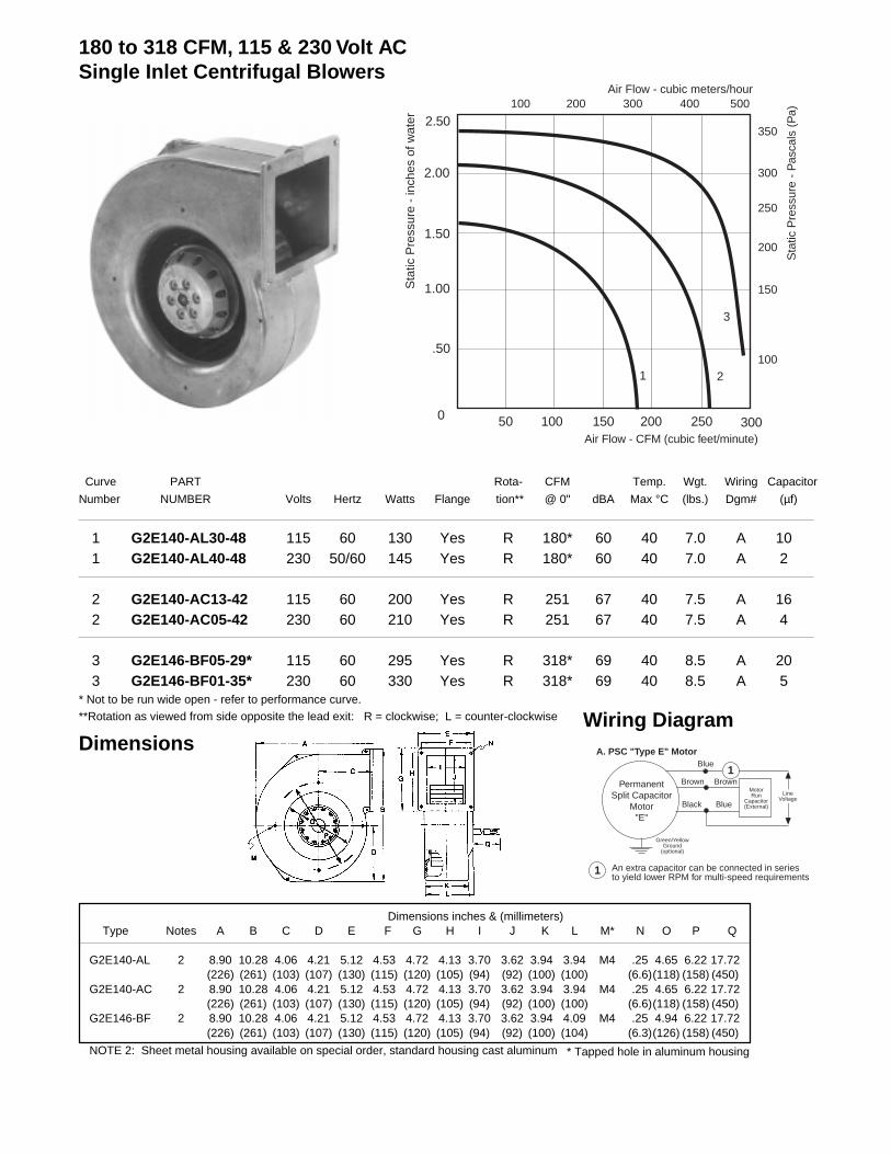
Curve PART Rota- CFM Temp. Wgt. Wiring Capacitor
Number NUMBER Volts Hertz Watts Flange tion** @ 0" dBA Max °C (lbs.) Dgm# (µf)
1 G2E140-AL30-48 115 60 130 Yes R 180* 60 40 7.0 A 101 G2E140-AL40-48 230 50/60 145 Yes R 180* 60 40 7.0 A 2
2 G2E140-AC13-42 115 60 200 Yes R 251 67 40 7.5 A 162 G2E140-AC05-42 230 60 210 Yes R 251 67 40 7.5 A 4
3 G2E146-BF05-29* 115 60 295 Yes R 318* 69 40 8.5 A 203 G2E146-BF01-35* 230 60 330 Yes R 318* 69 40 8.5 A 5
* Not to be run wide open - refer to performance curve.
**Rotation as viewed from side opposite the lead exit: R = clockwise; L = counter-clockwise
100 200 300 400 500
100
150
200
250
300
350
Air Flow - cubic meters/hour
Air Flow - CFM (cubic feet/minute)
Sta
tic P
ress
ure
- P
asca
ls (
Pa)
.50
1.00
2.00
2.50
0 50 100 200 300
3
2
Sta
tic P
ress
ure
- in
ches
of w
ater
150 250
1.50
1
180 to 318 CFM, 115 & 230 Volt ACSingle Inlet Centrifugal Blowers
Dimensions inches & (millimeters)Type Notes A B C D E F G H I J K L M* N O P Q
G2E140-AL 2 8.90 10.28 4.06 4.21 5.12 4.53 4.72 4.13 3.70 3.62 3.94 3.94 M4 .25 4.65 6.22 17.72(226) (261) (103) (107) (130) (115) (120) (105) (94) (92) (100) (100) (6.6)(118) (158) (450)
G2E140-AC 2 8.90 10.28 4.06 4.21 5.12 4.53 4.72 4.13 3.70 3.62 3.94 3.94 M4 .25 4.65 6.22 17.72(226) (261) (103) (107) (130) (115) (120) (105) (94) (92) (100) (100) (6.6)(118) (158) (450)
G2E146-BF 2 8.90 10.28 4.06 4.21 5.12 4.53 4.72 4.13 3.70 3.62 3.94 4.09 M4 .25 4.94 6.22 17.72(226) (261) (103) (107) (130) (115) (120) (105) (94) (92) (100) (104) (6.3)(126) (158) (450)
NOTE 2: Sheet metal housing available on special order, standard housing cast aluminum
PermanentSplit Capacitor
Motor"E"
Green/YellowGround
(optional)
Blue
Brown Brown
Black Blue
MotorRun
Capacitor(External)
LineVoltage
A. PSC "Type E" Motor
1
1 An extra capacitor can be connected in seriesto yield lower RPM for multi-speed requirements
Wiring DiagramDimensions
* Tapped hole in aluminum housing

Curve PART Rota- CFM Temp. Wgt. Wiring Capacitor
Number NUMBER Volts Hertz Watts Flange tion** @ 0" dBA Max °C (lbs.) Dgm# (µf)
1 G4E160-AB15-09 115 60 94 Yes R 262 67 65 7.0 A 71 G4E160-AB01-11 230 50/60 65 Yes R 262 67 65 7.0 A 2
2 G4E180-AB09-15 115 60 152 Yes R 350 58 45 7.5 A 102 G4E180-AB01-15 230 60 152 Yes R 350 58 45 7.5 A 3
* Not to be run wide open - refer to performance curve.
**Rotation as viewed from side opposite the lead exit: R = clockwise; L = counter-clockwise
100 200 300 400 500
50
100
150
200
250
300
350
Air Flow - cubic meters/hour
Air Flow - CFM (cubic feet/minute)
Sta
tic P
ress
ure
- P
asca
ls (
Pa)
.30
.60
1.20
1.50
0 50 100 200 300
2
1
Sta
tic P
ress
ure
- in
ches
of w
ater
150 250
.90
262 to 350 CFM, 115 & 230 Volt ACSingle Inlet Centrifugal Blowers
Dimensions inches & (millimeters)Type Notes A B C D E F G H I J K L M* N O P Q
G4E160-AB 2 8.90 10.27 4.06 4.21 5.12 4.53 4.72 4.13 3.70 3.62 3.94 3.94 M4 .260 5.12 6.89 17.72(226) (261) (103) (107) (130) (115) (120) (105) (94) (92) (100) (100) (6.6)(130) (175) (450)
G4E180-AB 2 10.24 11.54 4.72 4.80 4.92 4.33 5.51 4.72 3.39 4.33 3.62 4.13 M4 .275 5.91 7.64 17.72(260) (293) (120) (122) (125) (110) (140) (120) (86) (110) (92) (105) (7) (150) (194) (450)
Notes: 2. Sheet metal housing available on special order, cast aluminum is standard *Tapped hole in aluminum housing.
Dimensions
PermanentSplit Capacitor
Motor"E"
Green/YellowGround
(optional)
Blue
Brown Brown
Black Blue
MotorRun
Capacitor(External)
LineVoltage
A. PSC "Type E" Motor
1
1 An extra capacitor can be connected in seriesto yield lower RPM for multi-speed requirements
Wiring Diagram
175

Curve PART Rota- CFM Temp. Wgt. Wiring Capacitor
Number NUMBER Volts Hertz Watts Flange tion** @ 0" dBA Max °C (lbs.) Dgm# (µf)
1 RG20P-4/106478 115 60 410 Yes R 700* 83 40 22 C 161 RG20P-4/106479 230 60 380 Yes R 700* 83 40 22 C 4
2 RG22P-4/106480 115 60 490 Yes R 820* 86 40 30 C 252 RG22P-4/106481 230 60 490 Yes R 820* 86 40 30 C 6
* Not to be run wide open - refer to performance curve.
**Rotation as viewed from side opposite the lead exit: R = clockwise; L = counter-clockwise
700 to 820 CFM, 115 & 230 Volt ACSingle Inlet Centrifugal Blowers
Dimensions inches & (millimeters)Type Notes A B C D E F G H I J K L M N O P Q
RG20P 1 13.46 16.69 6.46 7.13 7.13 6.34 12.05 11.26 5.08 9.96 5.08 8.70 M10 .39 - - 17.72(342) (424) (164) (181) (181) (161) (306) (286) (129) (253) (129) (221) (10) (450)
RG22P 1 14.96 18.62 7.09 7.76 7.87 6.93 13.70 12.44 5.67 11.14 5.67 9.49 M12 .39 - - 17.72(380) (473) (180) (197) (200) (176) (348) (316) (144) (283) (144) (241) (10) (450)
NOTE 1: Sheet metal housing
DimensionsWiring Diagram
1 An extra capacitor can be connected in seriesto yield lower RPM for multi-speed requirements
PermanentSplit Capacitor
Motor
LineVoltage
T (T.O.P.)
T (T.O.P.)
U
Z
Z
U
k
k
1
1
2
2Capacitor Green/
Yellow
C. PSC Motor1
Tk leads are brown. U1 & U2 leads are blue. Z1 & Z2eads are black. Dotted lines not supplied on all design.
400 800 1200 1600 2000
100
300
400
500
600
Air Flow - cubic meters/hour
Air Flow - CFM (cubic feet/minute)
Sta
tic P
ress
ure
- P
asca
ls (
Pa)
200
.50
1.00
2.00
2.50
0 200 400 800 1200
2
1
Sta
tic P
ress
ure
- in
ches
of w
ater
600 1000
1.50

Curve PART Rota- CFM Temp. Wgt. Wiring Capacitor
Number NUMBER Volts Hertz Watts Flange tion** @ 0" dBA Max °C (lbs.) Dgm# (µf)
1 RG25P-4/106482 115 60 1100 Yes R 1250* 96 40 32 C 601 RG25P-4/106483 230 60 1100 Yes R 1250* 96 40 32 C 16
2 RG28P-4/106484 230 60 1800 Yes R 1100* 90 40 50 C 25* Not to be run wide open - refer to performance curve.
**Rotation as viewed from side opposite the lead exit: R = clockwise; L = counter-clockwise
Dimensions
600 1200 1800 2400 3000
100
300
400
500
600
Air Flow - cubic meters/hour
Air Flow - CFM (cubic feet/minute)
Sta
tic P
ress
ure
- P
asca
ls (
Pa)
200
.50
1.00
2.00
2.50
0 300 600 1200 1800
2
1
Sta
tic P
ress
ure
- in
ches
of w
ater
900 1500
1.50
1100 to 1250 CFM, 115 & 230 Volt ACSingle Inlet Centrifugal Blowers
Dimensions inches & (millimeters)Type Notes A B C D E F G H I J K L M N O P Q
RG25P 1 16.42 19.13 7.68 7.87 8.66 6.93 15.04 12.44 6.46 12.52 6.46 10.43 M12 .39 - - 17.72(417) (486) (195) (200) (220) (176) (382) (316) (164) (318) (164) (265) (10) (450)
RG28P 1 18.23 20.78 8.46 8.27 9.57 6.93 16.57 12.44 7.24 14.09 7.24 11.50 M12 .39 - - 17.72(463) (528) (215) (210) (243) (176) (421) (316) (184) (358) (184) (292) (10) (450)
NOTE 1: Sheet metal housing
Wiring Diagram
1 An extra capacitor can be connected in seriesto yield lower RPM for multi-speed requirements
PermanentSplit Capacitor
Motor
LineVoltage
T (T.O.P.)
T (T.O.P.)
U
Z
Z
U
k
k
1
1
2
2Capacitor Green/
Yellow
C. PSC Motor1
Tk leads are brown. U1 & U2 leads are blue. Z1 & Z2eads are black. Dotted lines not supplied on all design.