NUKE USER GUIDE VERSION 3thefoundry.s3.amazonaws.com/products/ocula/nuke/releases/3.0v3/... ·...
166
NUKE USER GUIDE VERSION 3.0V3
Transcript of NUKE USER GUIDE VERSION 3thefoundry.s3.amazonaws.com/products/ocula/nuke/releases/3.0v3/... ·...

NUKE USER GUIDE
VERSION 3.0V3
©2012 The Foundry Visionmongers Ltd. All rights reserved.Ocula 3.0 User Guide
This manual, as well as the software described in it, is furnished under licence and may only be used or copied in accordance with the terms of
such licence. This manual is provided for informational use only and is subject to change without notice. The Foundry assumes no responsibility or liability for any errors of inaccuracies that may appear in this book.
No part of this manual may be reproduced, stored in a retrieval system, or transmitted in any form without the prior written permission of The Foundry.
The Foundry logo is a trademark of The Foundry Visionmongers Ltd. Nuke is a registered trademark of The Foundry Visionmongers Ltd. All other
products or brands are trademarks or registered trademarks of their respective companies or organisations.
Software engineering Ben Kent, Abigail Brady, Bruno Nicoletti, Simon Robinson, Lucy Wilkes, Jonathan Starck, Jun Liu, Mailys Levassort, Jack Binks,
and Vilya Harvey.
Product testing: Sean Brice, Ben Minall, Dan Allum, Joel Braham, Mark Titchener, Morgan Barnett, Sam Smith, and Charles Quinn.
Writing and layout design Eija Närvänen.
Proof reading Eija Närvänen, Charles Quinn, and Joel Byrne.
The Foundry Ocula 3.0v3
Contents
Introduction About this User Guide. . . . . . . . . . . . . . . . . . . . . . . . . . . . . . . . . . . . . . . . 6
What’s New? . . . . . . . . . . . . . . . . . . . . . . . . . . . . . . . . . . . . . . . . . . . . . . . 6
Example Images . . . . . . . . . . . . . . . . . . . . . . . . . . . . . . . . . . . . . . . . . . . . 6
Installation . . . . . . . . . . . . . . . . . . . . . . . . . . . . . . . . . . . . . . . . . . . . . . . . 6
Moving the Plug-ins Directory . . . . . . . . . . . . . . . . . . . . . . . . . . . . . . . . 10
Licensing Ocula . . . . . . . . . . . . . . . . . . . . . . . . . . . . . . . . . . . . . . . . . . . . 10
Licensing Ocula on a Single Machine . . . . . . . . . . . . . . . . . . . . . . . . . . . 11
Licensing Ocula over a Network . . . . . . . . . . . . . . . . . . . . . . . . . . . . . . . 13
Other Foundry Products . . . . . . . . . . . . . . . . . . . . . . . . . . . . . . . . . . . . . 16
Solver Introduction . . . . . . . . . . . . . . . . . . . . . . . . . . . . . . . . . . . . . . . . . . . . . . 18
Inputs . . . . . . . . . . . . . . . . . . . . . . . . . . . . . . . . . . . . . . . . . . . . . . . . . . . 19
Quick Start . . . . . . . . . . . . . . . . . . . . . . . . . . . . . . . . . . . . . . . . . . . . . . . 20
Controls . . . . . . . . . . . . . . . . . . . . . . . . . . . . . . . . . . . . . . . . . . . . . . . . . 26
Example. . . . . . . . . . . . . . . . . . . . . . . . . . . . . . . . . . . . . . . . . . . . . . . . . . 31
DisparityGenerator Description . . . . . . . . . . . . . . . . . . . . . . . . . . . . . . . . . . . . . . . . . . . . . . . 32
Inputs . . . . . . . . . . . . . . . . . . . . . . . . . . . . . . . . . . . . . . . . . . . . . . . . . . . 33
Quick Start . . . . . . . . . . . . . . . . . . . . . . . . . . . . . . . . . . . . . . . . . . . . . . . 34
Controls . . . . . . . . . . . . . . . . . . . . . . . . . . . . . . . . . . . . . . . . . . . . . . . . . 38
Example. . . . . . . . . . . . . . . . . . . . . . . . . . . . . . . . . . . . . . . . . . . . . . . . . . 41
OcclusionDetector Description . . . . . . . . . . . . . . . . . . . . . . . . . . . . . . . . . . . . . . . . . . . . . . . 47
Inputs . . . . . . . . . . . . . . . . . . . . . . . . . . . . . . . . . . . . . . . . . . . . . . . . . . . 48
Quick Start . . . . . . . . . . . . . . . . . . . . . . . . . . . . . . . . . . . . . . . . . . . . . . . 48
Controls . . . . . . . . . . . . . . . . . . . . . . . . . . . . . . . . . . . . . . . . . . . . . . . . . 52
Example. . . . . . . . . . . . . . . . . . . . . . . . . . . . . . . . . . . . . . . . . . . . . . . . . . 53
ColourMatcher Description . . . . . . . . . . . . . . . . . . . . . . . . . . . . . . . . . . . . . . . . . . . . . . . 54
Inputs . . . . . . . . . . . . . . . . . . . . . . . . . . . . . . . . . . . . . . . . . . . . . . . . . . . 55
Quick Start . . . . . . . . . . . . . . . . . . . . . . . . . . . . . . . . . . . . . . . . . . . . . . . 55
Controls . . . . . . . . . . . . . . . . . . . . . . . . . . . . . . . . . . . . . . . . . . . . . . . . . 59
Example. . . . . . . . . . . . . . . . . . . . . . . . . . . . . . . . . . . . . . . . . . . . . . . . . . 62
FocusMatcher Description . . . . . . . . . . . . . . . . . . . . . . . . . . . . . . . . . . . . . . . . . . . . . . . 65
Inputs . . . . . . . . . . . . . . . . . . . . . . . . . . . . . . . . . . . . . . . . . . . . . . . . . . . 66

CONTENTS 4
Quick Start . . . . . . . . . . . . . . . . . . . . . . . . . . . . . . . . . . . . . . . . . . . . . . . 67
Controls . . . . . . . . . . . . . . . . . . . . . . . . . . . . . . . . . . . . . . . . . . . . . . . . . 71
Example. . . . . . . . . . . . . . . . . . . . . . . . . . . . . . . . . . . . . . . . . . . . . . . . . . 72
VerticalAligner Description . . . . . . . . . . . . . . . . . . . . . . . . . . . . . . . . . . . . . . . . . . . . . . . 77
Inputs . . . . . . . . . . . . . . . . . . . . . . . . . . . . . . . . . . . . . . . . . . . . . . . . . . . 79
Quick Start . . . . . . . . . . . . . . . . . . . . . . . . . . . . . . . . . . . . . . . . . . . . . . . 79
Controls . . . . . . . . . . . . . . . . . . . . . . . . . . . . . . . . . . . . . . . . . . . . . . . . . 83
Example. . . . . . . . . . . . . . . . . . . . . . . . . . . . . . . . . . . . . . . . . . . . . . . . . . 85
NewView Description . . . . . . . . . . . . . . . . . . . . . . . . . . . . . . . . . . . . . . . . . . . . . . . 87
Inputs . . . . . . . . . . . . . . . . . . . . . . . . . . . . . . . . . . . . . . . . . . . . . . . . . . . 88
Quick Start . . . . . . . . . . . . . . . . . . . . . . . . . . . . . . . . . . . . . . . . . . . . . . . 88
Controls . . . . . . . . . . . . . . . . . . . . . . . . . . . . . . . . . . . . . . . . . . . . . . . . . 89
Example. . . . . . . . . . . . . . . . . . . . . . . . . . . . . . . . . . . . . . . . . . . . . . . . . . 90
InteraxialShifter Description . . . . . . . . . . . . . . . . . . . . . . . . . . . . . . . . . . . . . . . . . . . . . . . 95
Inputs . . . . . . . . . . . . . . . . . . . . . . . . . . . . . . . . . . . . . . . . . . . . . . . . . . . 96
Quick Start . . . . . . . . . . . . . . . . . . . . . . . . . . . . . . . . . . . . . . . . . . . . . . . 96
Controls . . . . . . . . . . . . . . . . . . . . . . . . . . . . . . . . . . . . . . . . . . . . . . . . . 97
VectorGenerator Description . . . . . . . . . . . . . . . . . . . . . . . . . . . . . . . . . . . . . . . . . . . . . . . 99
Inputs . . . . . . . . . . . . . . . . . . . . . . . . . . . . . . . . . . . . . . . . . . . . . . . . . . 100
Quick Start . . . . . . . . . . . . . . . . . . . . . . . . . . . . . . . . . . . . . . . . . . . . . . 101
Controls . . . . . . . . . . . . . . . . . . . . . . . . . . . . . . . . . . . . . . . . . . . . . . . . 103
Example. . . . . . . . . . . . . . . . . . . . . . . . . . . . . . . . . . . . . . . . . . . . . . . . . 105
Retimer Description . . . . . . . . . . . . . . . . . . . . . . . . . . . . . . . . . . . . . . . . . . . . . . 106
Inputs . . . . . . . . . . . . . . . . . . . . . . . . . . . . . . . . . . . . . . . . . . . . . . . . . . 106
Quick Start . . . . . . . . . . . . . . . . . . . . . . . . . . . . . . . . . . . . . . . . . . . . . . 107
Controls . . . . . . . . . . . . . . . . . . . . . . . . . . . . . . . . . . . . . . . . . . . . . . . . 109
Example. . . . . . . . . . . . . . . . . . . . . . . . . . . . . . . . . . . . . . . . . . . . . . . . . 109
DepthToDisparity Description . . . . . . . . . . . . . . . . . . . . . . . . . . . . . . . . . . . . . . . . . . . . . . 113
Inputs . . . . . . . . . . . . . . . . . . . . . . . . . . . . . . . . . . . . . . . . . . . . . . . . . . 114
Quick Start . . . . . . . . . . . . . . . . . . . . . . . . . . . . . . . . . . . . . . . . . . . . . . 114
Controls . . . . . . . . . . . . . . . . . . . . . . . . . . . . . . . . . . . . . . . . . . . . . . . . 115
Example. . . . . . . . . . . . . . . . . . . . . . . . . . . . . . . . . . . . . . . . . . . . . . . . . 116
Ocula 3.0v3The Foundry

CONTENTS 5
DisparityToDepth Description . . . . . . . . . . . . . . . . . . . . . . . . . . . . . . . . . . . . . . . . . . . . . . 118
Inputs . . . . . . . . . . . . . . . . . . . . . . . . . . . . . . . . . . . . . . . . . . . . . . . . . . 118
Quick Start . . . . . . . . . . . . . . . . . . . . . . . . . . . . . . . . . . . . . . . . . . . . . . 119
Controls . . . . . . . . . . . . . . . . . . . . . . . . . . . . . . . . . . . . . . . . . . . . . . . . 120
Example. . . . . . . . . . . . . . . . . . . . . . . . . . . . . . . . . . . . . . . . . . . . . . . . . 120
DisparityViewer Description . . . . . . . . . . . . . . . . . . . . . . . . . . . . . . . . . . . . . . . . . . . . . . 124
Inputs . . . . . . . . . . . . . . . . . . . . . . . . . . . . . . . . . . . . . . . . . . . . . . . . . . 125
Quick Start . . . . . . . . . . . . . . . . . . . . . . . . . . . . . . . . . . . . . . . . . . . . . . 125
Controls . . . . . . . . . . . . . . . . . . . . . . . . . . . . . . . . . . . . . . . . . . . . . . . . 128
Example. . . . . . . . . . . . . . . . . . . . . . . . . . . . . . . . . . . . . . . . . . . . . . . . . 130
Appendix A: Release Notes
Ocula 3.0v3 . . . . . . . . . . . . . . . . . . . . . . . . . . . . . . . . . . . . . . . . . . . . . 134
Ocula 3.0v2 . . . . . . . . . . . . . . . . . . . . . . . . . . . . . . . . . . . . . . . . . . . . . 136
Ocula 3.0v1 . . . . . . . . . . . . . . . . . . . . . . . . . . . . . . . . . . . . . . . . . . . . . 137
Ocula 2.2v2 . . . . . . . . . . . . . . . . . . . . . . . . . . . . . . . . . . . . . . . . . . . . . 141
Ocula 2.2v1 . . . . . . . . . . . . . . . . . . . . . . . . . . . . . . . . . . . . . . . . . . . . . 142
Ocula 2.1v2 . . . . . . . . . . . . . . . . . . . . . . . . . . . . . . . . . . . . . . . . . . . . . 144
Ocula 2.1v1 . . . . . . . . . . . . . . . . . . . . . . . . . . . . . . . . . . . . . . . . . . . . . 145
Ocula 2.0v2 . . . . . . . . . . . . . . . . . . . . . . . . . . . . . . . . . . . . . . . . . . . . . 148
Ocula 2.0v1 . . . . . . . . . . . . . . . . . . . . . . . . . . . . . . . . . . . . . . . . . . . . . 150
Ocula 1.0v2 . . . . . . . . . . . . . . . . . . . . . . . . . . . . . . . . . . . . . . . . . . . . . 153
Ocula 1.0v1 . . . . . . . . . . . . . . . . . . . . . . . . . . . . . . . . . . . . . . . . . . . . . 154
Appendix B: Node Dependencies
Node Dependencies . . . . . . . . . . . . . . . . . . . . . . . . . . . . . . . . . . . . . . . 155
Appendix C: Third Party Licences
Third Party Licences . . . . . . . . . . . . . . . . . . . . . . . . . . . . . . . . . . . . . . . 157
Appendix C: End User License Agreement
End User License Agreement (EULA). . . . . . . . . . . . . . . . . . . . . . . . . . . 159
Index A-Z . . . . . . . . . . . . . . . . . . . . . . . . . . . . . . . . . . . . . . . . . . . . . . . . . . . . 166
Ocula 3.0v3The Foundry
INTRODUCTION
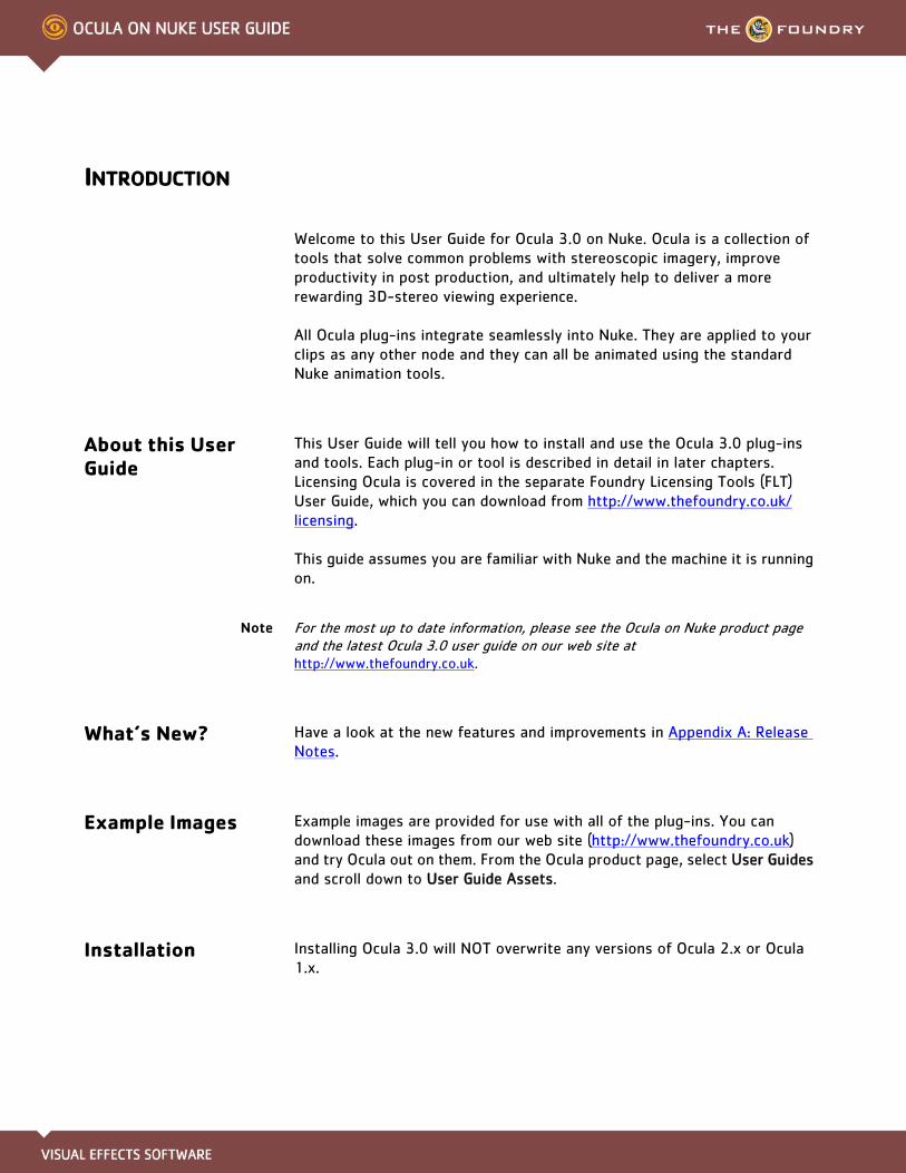
Welcome to this User Guide for Ocula 3.0 on Nuke. Ocula is a collection of tools that solve common problems with stereoscopic imagery, improve productivity in post production, and ultimately help to deliver a more rewarding 3D-stereo viewing experience.
All Ocula plug-ins integrate seamlessly into Nuke. They are applied to your clips as any other node and they can all be animated using the standard Nuke animation tools.
About this User Guide
This User Guide will tell you how to install and use the Ocula 3.0 plug-ins and tools. Each plug-in or tool is described in detail in later chapters. Licensing Ocula is covered in the separate Foundry Licensing Tools (FLT) User Guide, which you can download from http://www.thefoundry.co.uk/licensing.
This guide assumes you are familiar with Nuke and the machine it is running on.
Note For the most up to date information, please see the Ocula on Nuke product page and the latest Ocula 3.0 user guide on our web site at http://www.thefoundry.co.uk.
What’s New? Have a look at the new features and improvements in Appendix A: Release Notes.
Example Images Example images are provided for use with all of the plug-ins. You can download these images from our web site (http://www.thefoundry.co.uk) and try Ocula out on them. From the Ocula product page, select User Guides and scroll down to User Guide Assets.
Installation Installing Ocula 3.0 will NOT overwrite any versions of Ocula 2.x or Ocula 1.x.
INTRODUCTION 7Installation
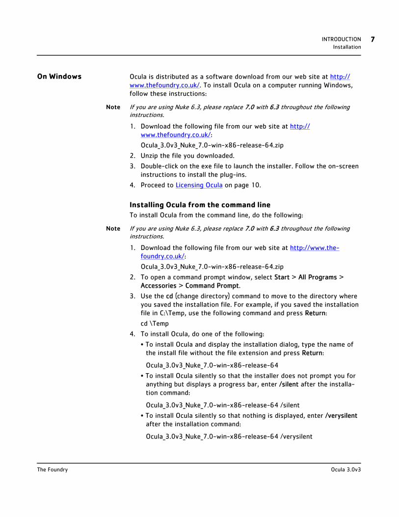
On Windows Ocula is distributed as a software download from our web site at http://www.thefoundry.co.uk/. To install Ocula on a computer running Windows, follow these instructions:
Note If you are using Nuke 6.3, please replace 7.0 with 6.3 throughout the following instructions.
1. Download the following file from our web site at http://www.thefoundry.co.uk/:
Ocula_3.0v3_Nuke_7.0-win-x86-release-64.zip
2. Unzip the file you downloaded.
3. Double-click on the exe file to launch the installer. Follow the on-screen instructions to install the plug-ins.
4. Proceed to Licensing Ocula on page 10.
Installing Ocula from the command line
To install Ocula from the command line, do the following:
Note If you are using Nuke 6.3, please replace 7.0 with 6.3 throughout the following instructions.
1. Download the following file from our web site at http://www.the-foundry.co.uk/:
Ocula_3.0v3_Nuke_7.0-win-x86-release-64.zip
2. To open a command prompt window, select Start > All Programs > Accessories > Command Prompt.
3. Use the cd (change directory) command to move to the directory where you saved the installation file. For example, if you saved the installation file in C:\Temp, use the following command and press Return:
cd \Temp
4. To install Ocula, do one of the following:
• To install Ocula and display the installation dialog, type the name of the install file without the file extension and press Return:
Ocula_3.0v3_Nuke_7.0-win-x86-release-64
• To install Ocula silently so that the installer does not prompt you for anything but displays a progress bar, enter /silent after the installa-tion command:
Ocula_3.0v3_Nuke_7.0-win-x86-release-64 /silent
• To install Ocula silently so that nothing is displayed, enter /verysilent after the installation command:
Ocula_3.0v3_Nuke_7.0-win-x86-release-64 /verysilent
Ocula 3.0v3The Foundry
INTRODUCTION 8Installation
Note By running a silent install of Ocula, you agree to the terms of the End User License Agreement. To see this agreement, please refer to Appendix C: End User License Agreement on page 159 or run the installer in standard, non-silent mode.
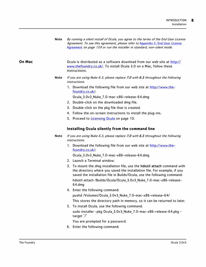
On Mac Ocula is distributed as a software download from our web site at http://www.thefoundry.co.uk/. To install Ocula 3.0 on a Mac, follow these instructions:
Note If you are using Nuke 6.3, please replace 7.0 with 6.3 throughout the following instructions.
1. Download the following file from our web site at http://www.the-foundry.co.uk/:
Ocula_3.0v3_Nuke_7.0-mac-x86-release-64.dmg
2. Double-click on the downloaded dmg file.
3. Double-click on the pkg file that is created.
4. Follow the on-screen instructions to install the plug-ins.
5. Proceed to Licensing Ocula on page 10.
Installing Ocula silently from the command line
Note If you are using Nuke 6.3, please replace 7.0 with 6.3 throughout the following instructions.
1. Download the following file from our web site at http://www.the-foundry.co.uk/:
Ocula_3.0v3_Nuke_7.0-mac-x86-release-64.dmg
2. Launch a Terminal window.
3. To mount the dmg installation file, use the hdiutil attach command with the directory where you saved the installation file. For example, if you saved the installation file in Builds/Ocula, use the following command:
hdiutil attach /Builds/Ocula/Ocula_3.0v3_Nuke_7.0-mac-x86-release-64.dmg
4. Enter the following command:
pushd /Volumes/Ocula_3.0v3_Nuke_7.0-mac-x86-release-64/
This stores the directory path in memory, so it can be returned to later.
5. To install Ocula, use the following command:
sudo installer -pkg Ocula_3.0v3_Nuke_7.0-mac-x86-release-64.pkg -target "/"
You are prompted for a password.
6. Enter the following command:
Ocula 3.0v3The Foundry
INTRODUCTION 9Installation
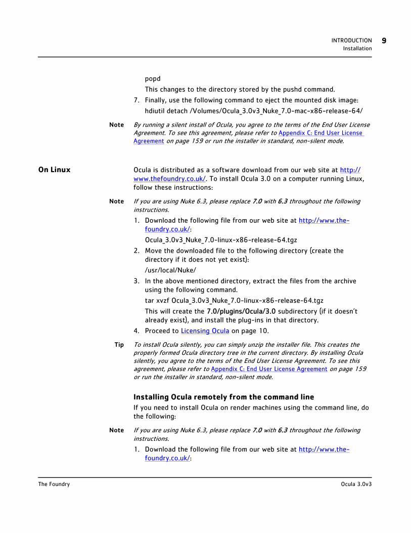
popd
This changes to the directory stored by the pushd command.
7. Finally, use the following command to eject the mounted disk image:
hdiutil detach /Volumes/Ocula_3.0v3_Nuke_7.0-mac-x86-release-64/
Note By running a silent install of Ocula, you agree to the terms of the End User License Agreement. To see this agreement, please refer to Appendix C: End User License Agreement on page 159 or run the installer in standard, non-silent mode.
On Linux Ocula is distributed as a software download from our web site at http://www.thefoundry.co.uk/. To install Ocula 3.0 on a computer running Linux, follow these instructions:
Note If you are using Nuke 6.3, please replace 7.0 with 6.3 throughout the following instructions.
1. Download the following file from our web site at http://www.the-foundry.co.uk/:
Ocula_3.0v3_Nuke_7.0-linux-x86-release-64.tgz
2. Move the downloaded file to the following directory (create the directory if it does not yet exist):
/usr/local/Nuke/
3. In the above mentioned directory, extract the files from the archive using the following command.
tar xvzf Ocula_3.0v3_Nuke_7.0-linux-x86-release-64.tgz
This will create the 7.0/plugins/Ocula/3.0 subdirectory (if it doesn’t already exist), and install the plug-ins in that directory.
4. Proceed to Licensing Ocula on page 10.
Tip To install Ocula silently, you can simply unzip the installer file. This creates the properly formed Ocula directory tree in the current directory. By installing Ocula silently, you agree to the terms of the End User License Agreement. To see this agreement, please refer to Appendix C: End User License Agreement on page 159 or run the installer in standard, non-silent mode.
Installing Ocula remotely from the command line
If you need to install Ocula on render machines using the command line, do the following:
Note If you are using Nuke 6.3, please replace 7.0 with 6.3 throughout the following instructions.
1. Download the following file from our web site at http://www.the-foundry.co.uk/:
Ocula 3.0v3The Foundry

INTRODUCTION 10Moving the Plug-ins Directory
Ocula_3.0v3_Nuke_7.0-linux-x86-release-64.tgz
2. Extract the installer from the tgz archive with the following terminal command:
tar xvzf Ocula_3.0v3_Nuke_7.0-linux-x86-release-64.tgz
This gives you an installer file.
3. Use the following terminal command to log in to your render machine as root:
ssh root@render_machine
Replace render_machine with the name of your render node.
4. Make a directory to install Ocula to:
mkdir /usr/local/Ocula3.0v3
5. Copy the installer file from the machine that you downloaded it on to your render machine with a command like:
scp root@download_machine:/tmp/Ocula_3.0v3_Nuke_7.0-linux-x86-release-64-installer root@render_machine:/usr/local/Ocula3.0v3/
Replace download_machine with the name of the machine you down-loaded the installer file to, and render_machine with the name of your render node.
6. Unzip the installer file to unpack its contents into your Ocula directory:
cd /usr/local/Ocula3.0v3
unzip Ocula_3.0v3_Nuke_7.0-linux-x86-release-64-installer
7. Repeat steps 3-6 for each render machine.
Moving the Plug-ins Directory
You can put the Ocula plug-ins anywhere as long as you set the environment variable NUKE_PATH to point to it.
Licensing Ocula
About Licences If you simply want to try out Ocula, you can obtain a trial licence, which allows you to run Ocula for free for 15 days.
To use Ocula after this trial period, you need either a valid license key or a floating license and server running the Foundry Licensing Tools (FLT):
• Licence Keys—These can be used to install and activate node locked (also known as uncounted) licences. Node locked licences allow you to
Ocula 3.0v3The Foundry

INTRODUCTION 11Licensing Ocula on a Single Machine
use Ocula on a single machine. This licence will not work on a different machine and if you need it to, you’ll have to transfer your licence. Node locked licences do not require additional licensing software to be installed. See Licensing Ocula on a Single Machine for more information.
• Floating Licences—also known as counted licences, enable Ocula to work on any networked client machine. The floating licence should be put on the server and is locked to a unique number on that server. Floating licences on a server require additional software to be installed. This software manages those licences on the server, giving licences out to client stations that want them. The software you need to manage these licenses is called the Foundry License Tools (FLT) and it can be freely downloaded from our web site. Floating licences often declare a port number on the server line and a port number on the vendor line. See Licensing Ocula over a Network for more information.
The instructions below run through both licensing methods, and you can find a more detailed description in the Foundry Licensing Tools User Guide available on our website: http://www.thefoundry.co.uk/support/licensing/tools/rlm
Licensing Ocula on a Single Machine
Obtaining a Licence Key
You can purchase licence keys by:
• going to our web site at http://www.thefoundry.co.uk/,
• e-mailing us at [email protected],
• phoning our London office at +44 20 7968 6828 or our Los Angeles office at +1 (310) 399 4555.
To generate a licence key, we need to know your System ID. The System ID (sometimes called Host ID or rlmhostid) returns a unique number for your computer. We lock our licence keys to the System ID.
To display your System ID, do the following:
• On Windows and Mac
Download the Foundry License Utility (FLU) from www.thefoundry.co.uk/support/licensing/ and run it. The System ID is displayed at the bottom of the window.
Ocula 3.0v3The Foundry
INTRODUCTION 12Licensing Ocula on a Single Machine
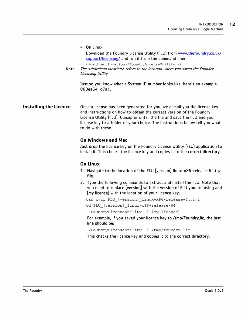
• On Linux
Download the Foundry License Utility (FLU) from www.thefoundry.co.uk/support/licensing/ and run it from the command line:<download location>/FoundryLicenseUtility -i
Note The <download location> refers to the location where you saved the Foundry Licensing Utility.
Just so you know what a System ID number looks like, here’s an example: 000ea641d7a1.
Installing the Licence Once a license has been generated for you, we e-mail you the license key and instructions on how to obtain the correct version of the Foundry License Utility (FLU). Gunzip or untar the file and save the FLU and your license key to a folder of your choice. The instructions below tell you what to do with these.
On Windows and Mac
Just drop the licence key on the Foundry License Utility (FLU) application to install it. This checks the licence key and copies it to the correct directory.
On Linux
1. Navigate to the location of the FLU_[version]_linux-x86-release-64.tgz file.
2. Type the following commands to extract and install the FLU. Note that you need to replace [version] with the version of FLU you are using and [my licence] with the location of your licence key.
tar xvzf FLU_[version]_linux-x86-release-64.tgz
cd FLU_[version]_linux-x86-release-64
./FoundryLicenseUtility -l [my license]
For example, if you saved your licence key to /tmp/Foundry.lic, the last line should be:
./FoundryLicenseUtility -l /tmp/foundry.lic
This checks the licence key and copies it to the correct directory.
Ocula 3.0v3The Foundry

INTRODUCTION 13Licensing Ocula over a Network
Licensing Ocula over a Network
Obtaining Floating Licences
You can purchase a floating licence key by:
• going to our web site at http://www.thefoundry.co.uk/,
• e-mailing us at [email protected],
• phoning our London office at +44 20 7968 6828 or our Los Angeles office at +1 (310) 399 4555.
To generate you a licence key, we need to know the System ID of the machine that will act as the server. The System ID (sometimes called Host ID or rlmhostid) returns a unique number for the computer. We lock our licence keys to the System ID. See Installing Floating Licences.
To display your System ID, do the following:
• On Windows and Mac
Download the Foundry License Utility (FLU) from www.thefoundry.co.uk/support/licensing/ and run it. The System ID is displayed at the bottom of the window.
• On Linux
Download the Foundry License Utility (FLU) from www.thefoundry.co.uk/support/licensing/ and run it from the command line:<download location>/FoundryLicenseUtility -i
Note The <download location> refers to the location where you saved the Foundry Licensing Utility.
Note The System ID needs to be from the machine that will act as the server and not one of the client machines.
Just so you know what a System ID number looks like, here’s an example: 000ea641d7a1.
Installing Floating Licences
Once a floating licence has been created for you, we e-mail you a tgz file containing the license key and instructions on how to obtain the correct version of the Foundry License Utility (FLU). Gunzip or untar the file and save the FLU and your license key to a folder of your choice.
Having installed a floating licence key, you need to install some additional software (FLT) to manage the licences on your network. Then you need to tell the client machines where to find the licences.
Ocula 3.0v3The Foundry
INTRODUCTION 14Licensing Ocula over a Network
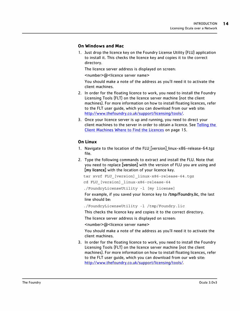
On Windows and Mac
1. Just drop the licence key on the Foundry License Utility (FLU) application to install it. This checks the licence key and copies it to the correct directory.
The licence server address is displayed on screen:
<number>@<licence server name>
You should make a note of the address as you’ll need it to activate the client machines.
2. In order for the floating licence to work, you need to install the Foundry Licensing Tools (FLT) on the licence server machine (not the client machines). For more information on how to install floating licences, refer to the FLT user guide, which you can download from our web site: http://www.thefoundry.co.uk/support/licensing/tools/.
3. Once your licence server is up and running, you need to direct your client machines to the server in order to obtain a licence. See Telling the Client Machines Where to Find the Licences on page 15.
On Linux
1. Navigate to the location of the FLU_[version]_linux-x86-release-64.tgz file.
2. Type the following commands to extract and install the FLU. Note that you need to replace [version] with the version of FLU you are using and [my licence] with the location of your licence key.
tar xvzf FLU_[version]_linux-x86-release-64.tgz
cd FLU_[version]_linux-x86-release-64
./FoundryLicenseUtility -l [my license]
For example, if you saved your licence key to /tmp/Foundry.lic, the last line should be:
./FoundryLicenseUtility -l /tmp/Foundry.lic
This checks the licence key and copies it to the correct directory.
The licence server address is displayed on screen:
<number>@<licence server name>
You should make a note of the address as you’ll need it to activate the client machines.
3. In order for the floating licence to work, you need to install the Foundry Licensing Tools (FLT) on the licence server machine (not the client machines). For more information on how to install floating licences, refer to the FLT user guide, which you can download from our web site: http://www.thefoundry.co.uk/support/licensing/tools/.
Ocula 3.0v3The Foundry
INTRODUCTION 15Licensing Ocula over a Network
4. Once your licence server is up and running, you need to direct your client machines to the server in order to obtain a licence. See Telling the Client Machines Where to Find the Licences on page 15.
Telling the Client Machines Where to Find the Licences
In order for the client machines to get a licence from the server, they need to be told where to look.
On Windows and Mac
1. Launch the Foundry License Utility (FLU).
2. Make sure you are viewing the License Install tab and copy and paste in an RLM server line:
HOST <server name> any <port>
For example: HOST red any 4101
This creates and installs both a client license.
3. Repeat this process for each machine you wish to have access to licenses on the server.
On Linux
1. Launch a shell and navigate to the location of the FLU_[version]_linux-x86-release-64.tgz file.
2. Type the following commands, replacing [version] with the version of FLU you are using:tar xvzf FLU_[version]_linux-x86-release-64.tgz
cd FLU_[version]_linux-x86-release-64
./FoundryLicenseUtility -c <port>@<server name>
For example, the last line may be: ./FoundryLicenseUtility -c 4101@red
This creates and installs both a client license.
3. Repeat this process for each machine you wish to have access to licenses on the server.
Further Reading For more information on licensing Ocula, displaying the System ID number, setting up a floating licence server, adding new licence keys, and managing licence usage across a network, you should read the Foundry Licensing Tools User Guide available on our web site:http://www.thefoundry.co.uk/support/licensing/tools/
Ocula 3.0v3The Foundry
INTRODUCTION 16Other Foundry Products
Other Foundry Products
The Foundry is a leading developer of visual effects and image processing technologies for film and video post production. Its stand-alone products include Nuke, Hiero, Mari, Katana, and Storm. The Foundry also supplies a suite of plug-ins, including Ocula, Furnace and FurnaceCore, Keylight, RollingShutter, Kronos, and CameraTracker for a variety of compositing platforms, including Adobe® After Effects®, Autodesk® Flame®, Avid® DS™, and Apple’s Final Cut Pro®. For the full list of products and supported platforms, visit our website at http://www.thefoundry.co.uk.
Nuke is an Academy Award® winning compositor. It has been used to create extraordinary images on scores of feature films, including Avatar, District 9, The Dark Knight, Iron Man, Quantum of Solace, The Curious Case of Benjamin Button, Transformers, and Pirates of the Caribbean: At World’s End.
Hiero is a collaborative, scriptable timeline tool that conforms edit decision lists and parcels out VFX shots to artists, allowing progress to be viewed in context, and liberating your finishing systems and artists for more creative tasks.
Mari is a creative texture-painting tool that can handle extremely complex or texture-heavy projects. It was developed at Weta Digital and has been used on films, such as District 9, The Day the Earth Stood Still, The Lovely Bones, and Avatar.
Katana is a look development and lighting tool, replacing the conventional CG pipeline with a flexible recipe-based asset workflow. Its node-based approach allows rapid turnaround of high-complexity shots, while keeping artists in control and reducing in-house development overheads. Extensive APIs mean it integrates with a variety of renderers and your pre-existing shader libraries and workflow tools.
Ocula is a collection of tools that solve common problems with stereoscopic imagery, improve productivity in post production, and ultimately help to deliver a more rewarding 3D-stereo viewing experience.
Furnace and FurnaceCore are collections of film tools. Many of the algorithms utilise motion estimation technology to speed up common compositing tasks. Plug-ins include wire removal, rig removal, steadiness, deflicker, degrain and regrain, retiming, and texture tools.
Keylight is an industry-proven blue/green screen keyer, giving results that look photographed, not composited. The Keylight algorithm was developed by the Computer Film Company who were honoured with a technical achievement award for digital compositing from the Academy of Motion Picture Arts and Sciences.
Ocula 3.0v3The Foundry
INTRODUCTION 17Other Foundry Products
RollingShutter is a plug-in that tackles image-distortion problems often experienced by users of CMOS cameras. The plug-in will often vastly improve the look of distorted footage, by either minimising or eradicating image distortions. Unlike solutions tied to camera stabilisation, that stretch the image as a whole, the RollingShutter plug-in compensates for local skewing and distortion in the scene, by correcting each object individually.
Kronos is a plug-in that retimes footage using motion vectors to generate additional images between frames. Utilising NVIDIA’s CUDA technology, Kronos optimises your workflow by using both the CPU and GPU.
CameraTracker is an After Effects plug-in allowing you to pull 3D motion tracks and matchmoves without having to leave After Effects. It analyses the source sequence and extracts the original camera's lens and motion parameters, allowing you to composite 2D or 3D elements correctly with reference to the camera used to film the shot.
Storm is a product developed in-house at The Foundry to assist RED Digital Cinema camera production workflows from on-set to delivery. It acts as a hub, providing access to both metadata and original RAW image files throughout the production process.
Visit The Foundry’s web site at http://www.thefoundry.co.uk for further details.
Ocula 3.0v3The Foundry

SOLVER
Introduction The O_Solver plug-in defines the geometric relationship between the two views in the input images (that is, the camera relationship or solve). This is necessary if you want to use DisparityGenerator, VectorGenerator, or VerticalAligner down the tree.
To define the camera relationship, O_Solver detects a number of features in one view and locates the corresponding features in the other (Figure 1). The feature matches and analysis data are not available until you have set at least one keyframe on O_Solver. Any frames set as keyframes show up on the Viewer timeline and can be visualised in the Curve Editor and Dope Sheet.
Figure 1. O_Solver detects features in each view and tries to match them.
O_Solver only calculates the solve at the keyframes. The solves for all other frames are created by interpolating between the results on the keyframes on either side. Interpolating between keyframes ensures that the calculated solve varies smoothly across the sequence.
The output of the O_Solver node consists of:
• the unaltered input images, and
• the results of the feature detection and analysis, which are passed down the node tree as hidden metadata.
the location of the corresponding feature in the other view
a detected feature
SOLVER 19Inputs
Because the results of the analysis are available downstream, you can use multiple Ocula nodes in the tree without having to re-analyse the camera relationship. However, if a node generates or modifies views, the current metadata becomes invalid and is removed from the tree from that point forward.
Note that the camera relationship is the same for any images filmed using a particular camera setup. When you have found an image with features that O_Solver is able to match well, you can re-use the analysis of that image on other images shot with the same camera setup.
To get the best possible results, you can identify features to ignore in the analysis. This can be done either by deleting features displayed in a Viewer overlay, or by supplying a mask in the Ignore input.
You can also add your own feature matches to the automatically detected ones. O_Solver considers any feature matches you’ve added yourself superior to the ones it detects automatically and pays them more attention. This can also influence which of the automatically detected features are included in the final solve. To force the feature matches to be recalculated based on the manual feature matches, use the Re-analyse Frame button.
If you have a pretracked camera that describes the camera setup used to shoot the images, you can also supply this in the Camera input. If you connect the Camera node before adding a keyframe, the automatically-detected feature matches are validated against the input camera. Alternatively, you can add the Camera node after the analysis and use the Re-analyse Frame button to recalculate matches based on the input camera. For more information, see Inputs below.
Tip When shooting bluescreen or greenscreen footage, you may be able to improve O_Solver's feature matching by adding markers to the shot. If you want to do so, make sure the markers are as unreflective as possible and stagger them over depth. Then, add user matches on the markers to correct the calculated alignment.
Inputs O_Solver has three inputs:
• Source - A stereo pair of images. These can either be the images you want to work on, or another pair of images shot with the same camera setup.
• Ignore - A mask that specifies areas to ignore during the feature detection and analysis. This can be useful if an area in the Source image is producing incorrectly matched features. This input is optional.
Ocula 3.0v3The Foundry
SOLVER 20Quick Start
• Camera - A pretracked Nuke stereo camera that describes the camera setup used to shoot the Source image. This can be a camera you have tracked with the CameraTracker node or imported to Nuke from a third-party camera tracking application. This input is optional.
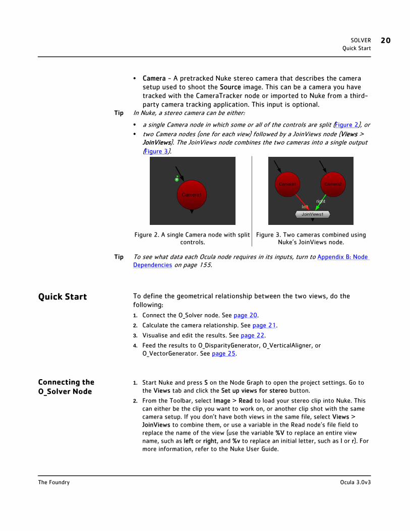
Tip In Nuke, a stereo camera can be either:
• a single Camera node in which some or all of the controls are split (Figure 2), or
• two Camera nodes (one for each view) followed by a JoinViews node (Views > JoinViews). The JoinViews node combines the two cameras into a single output
(Figure 3).
Tip To see what data each Ocula node requires in its inputs, turn to Appendix B: Node Dependencies on page 155.
Quick Start To define the geometrical relationship between the two views, do the following:
1. Connect the O_Solver node. See page 20.
2. Calculate the camera relationship. See page 21.
3. Visualise and edit the results. See page 22.
4. Feed the results to O_DisparityGenerator, O_VerticalAligner, or O_VectorGenerator. See page 25.
Connecting the O_Solver Node
1. Start Nuke and press S on the Node Graph to open the project settings. Go to the Views tab and click the Set up views for stereo button.
2. From the Toolbar, select Image > Read to load your stereo clip into Nuke. This can either be the clip you want to work on, or another clip shot with the same camera setup. If you don’t have both views in the same file, select Views > JoinViews to combine them, or use a variable in the Read node’s file field to replace the name of the view (use the variable %V to replace an entire view name, such as left or right, and %v to replace an initial letter, such as l or r). For more information, refer to the Nuke User Guide.
Figure 2. A single Camera node with split controls.
Figure 3. Two cameras combined using Nuke’s JoinViews node.
Ocula 3.0v3The Foundry

SOLVER 21Quick Start
3. Select Ocula > Ocula 3.0 > O_Solver to insert an O_Solver node after either the stereo clip or the JoinViews node (if you inserted one in the previous step).
4. Connect a Viewer to the O_Solver node.
Figure 4. The node tree with O_Solver.
5. Proceed to Calculating the Camera Relationship below.
Calculating the Camera Relationship
1. Open the O_Solver controls. Under Views to Use, you can see all the views that exist in your project settings. Select the two views you want to use for the left and right eye when calculating the camera relationship.
The two views you selected are mapped for the left and right eye.
2. If you have a pretracked Nuke stereo camera that describes the camera setup used to shoot the Source image, connect that to O_Solver’s Camera input. O_Solver uses the camera information to calculate the relationship between the two views.
3. Set at least one keyframe for O_Solver to analyse. Use the Viewer timeline to scrub to a frame that is easy to match between views - ideally, a frame with enough picture detail, but no motion blur, occluding fog, or dust. Then, click Add Key. Repeat as necessary:
• If the camera rig doesn't change, you can set keyframes only on one frame or far apart (for example, on the first and last frames). If you do set a few key-frames, you can also check Single Solve from All Keys in the O_Solver controls. This tells O_Solver to calculate a single solve using all keyframes, which can improve the results.
• If you know there is a zoom or change in the camera setup on certain frames, you need to add more keyframes in between. Leave Single Solve from All Keys unchecked to use a separate solve for each keyframe, and place keyframes where the camera alignment changes.
O_Solver analyses the keyframes you added and, if it finds more than one key-frame, it interpolates the results between them. Interpolating between key-frames ensures that the calculated camera relationship varies smoothly across the sequence.
To visualise the keyframed analysis in the Curve Editor or Dope Sheet, right-click on the Analysis Key field and select Curve editor or Dope sheet. Note, however, that you cannot edit the curve in either.
4. Proceed to Reviewing and Editing the Results below.
Note Once O_Solver has automatically detected feature matches, they are fixed and do not update in response to changes in the node tree. You can edit them manually,
Ocula 3.0v3The Foundry
SOLVER 22Quick Start
however, or click Re-analyse Frame to force O_Solver to recalculate the current frame. The automatically detected feature matches are also updated if you adjust any O_Solver controls that affect the analysis.
Reviewing and Editing the Results
1. Set Display to Keyframe Matches (or press M on the Viewer) and make sure you are viewing a keyframe.
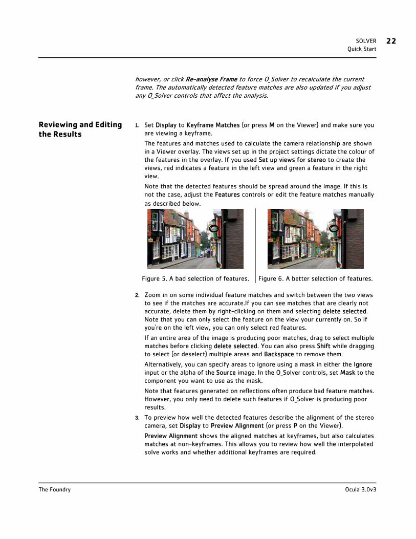
The features and matches used to calculate the camera relationship are shown in a Viewer overlay. The views set up in the project settings dictate the colour of the features in the overlay. If you used Set up views for stereo to create the views, red indicates a feature in the left view and green a feature in the right view.
Note that the detected features should be spread around the image. If this is not the case, adjust the Features controls or edit the feature matches manually
as described below.
2. Zoom in on some individual feature matches and switch between the two views to see if the matches are accurate.If you can see matches that are clearly not accurate, delete them by right-clicking on them and selecting delete selected. Note that you can only select the feature on the view your currently on. So if you're on the left view, you can only select red features.
If an entire area of the image is producing poor matches, drag to select multiple matches before clicking delete selected. You can also press Shift while dragging to select (or deselect) multiple areas and Backspace to remove them.
Alternatively, you can specify areas to ignore using a mask in either the Ignore input or the alpha of the Source image. In the O_Solver controls, set Mask to the component you want to use as the mask.
Note that features generated on reflections often produce bad feature matches. However, you only need to delete such features if O_Solver is producing poor results.
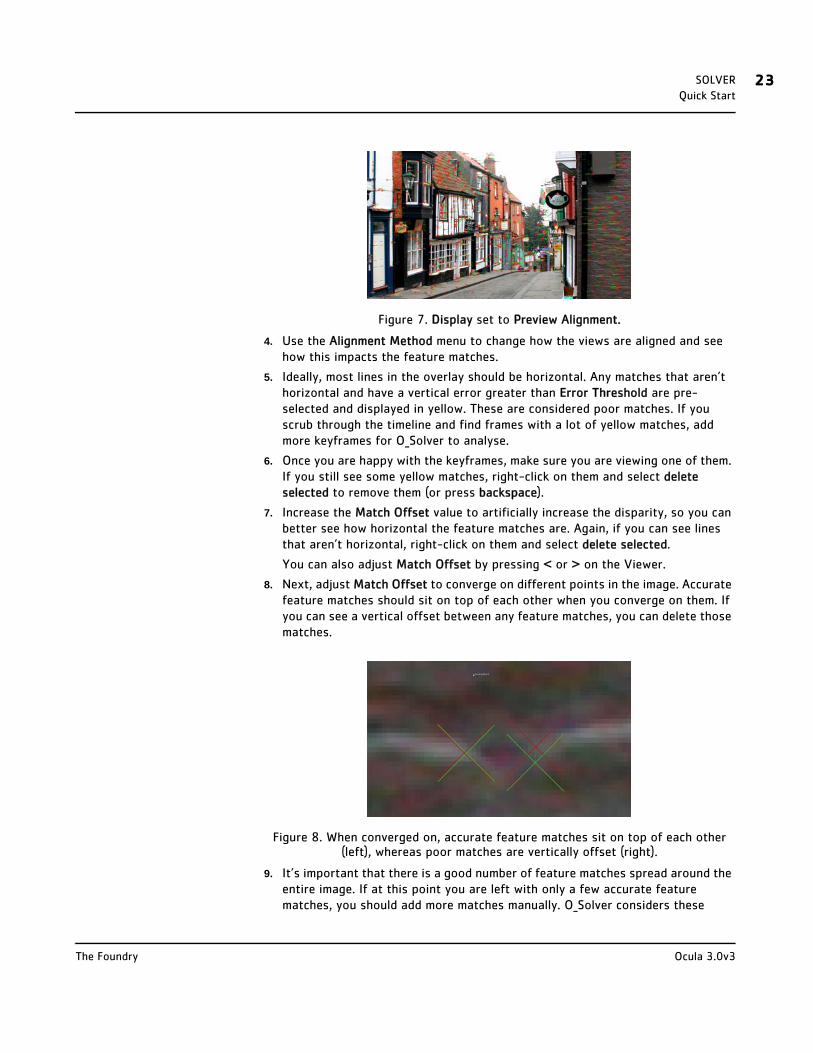
3. To preview how well the detected features describe the alignment of the stereo camera, set Display to Preview Alignment (or press P on the Viewer).
Preview Alignment shows the aligned matches at keyframes, but also calculates matches at non-keyframes. This allows you to review how well the interpolated solve works and whether additional keyframes are required.
Figure 5. A bad selection of features. Figure 6. A better selection of features.
Ocula 3.0v3The Foundry
SOLVER 23Quick Start
Figure 7. Display set to Preview Alignment.
4. Use the Alignment Method menu to change how the views are aligned and see how this impacts the feature matches.
5. Ideally, most lines in the overlay should be horizontal. Any matches that aren’t horizontal and have a vertical error greater than Error Threshold are pre-selected and displayed in yellow. These are considered poor matches. If you scrub through the timeline and find frames with a lot of yellow matches, add more keyframes for O_Solver to analyse.
6. Once you are happy with the keyframes, make sure you are viewing one of them. If you still see some yellow matches, right-click on them and select delete selected to remove them (or press backspace).
7. Increase the Match Offset value to artificially increase the disparity, so you can better see how horizontal the feature matches are. Again, if you can see lines that aren’t horizontal, right-click on them and select delete selected.
You can also adjust Match Offset by pressing < or > on the Viewer.
8. Next, adjust Match Offset to converge on different points in the image. Accurate feature matches should sit on top of each other when you converge on them. If you can see a vertical offset between any feature matches, you can delete those matches.
Figure 8. When converged on, accurate feature matches sit on top of each other (left), whereas poor matches are vertically offset (right).
9. It’s important that there is a good number of feature matches spread around the entire image. If at this point you are left with only a few accurate feature matches, you should add more matches manually. O_Solver considers these
Ocula 3.0v3The Foundry
SOLVER 24Quick Start
manually added matches superior to the ones detected automatically and pays them more attention when calculating the final results.
You should also add more feature matches manually if the automatic feature detection didn’t produce enough matches in some parts of the image. In cases like this, it’s a good idea to add at least four user matches (one in each corner of the image), but the more (accurate) matches you have, the better!
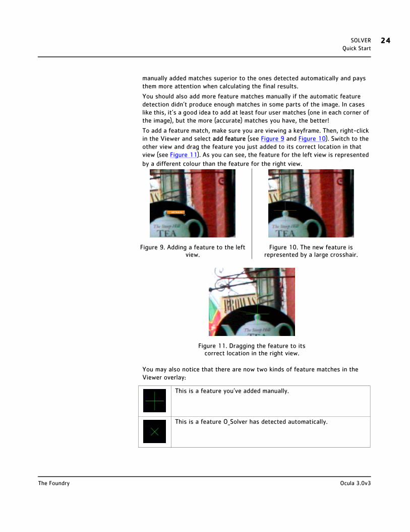
To add a feature match, make sure you are viewing a keyframe. Then, right-click in the Viewer and select add feature (see Figure 9 and Figure 10). Switch to the other view and drag the feature you just added to its correct location in that view (see Figure 11). As you can see, the feature for the left view is represented
by a different colour than the feature for the right view.
You may also notice that there are now two kinds of feature matches in the Viewer overlay:
Figure 9. Adding a feature to the left view.
Figure 10. The new feature is represented by a large crosshair.
Figure 11. Dragging the feature to its correct location in the right view.
This is a feature you’ve added manually.
This is a feature O_Solver has detected automatically.
Ocula 3.0v3The Foundry

SOLVER 25Quick Start
10. If you’re not happy with the results, try using O_Solver on another sequence shot with the same camera setup. Then, connect the O_Solver node to the Solver input of O_DisparityGenerator, O_VerticalAligner, or O_VectorGenerator.
Note When you calculate a camera relationship for a different sequence and attach it to the Solver input of O_DisparityGenerator, O_VerticalAligner, or O_VectorGenerator, the camera relationship is still accessed at the current time frame. For example, if the Solver clip has frames 1-10 and the Source clip has frames 1-100, the camera relationship from frame 10 of the Solver clip is used for frames 10-100. You can resolve this by getting O_Solver to just give a single result that is always used. If this is not the case, the sequences may need to be retimed so that the calculated camera relationship is consistent with the sequence that is being analysed.
11. Once you are happy with the results of O_Solver, proceed to Feeding the Results to Other Ocula Nodes below.
Feeding the Results to Other Ocula Nodes
1. Do one of the following:
• Select Ocula > Ocula 3.0 > O_DisparityGenerator to insert an O_DisparityGenerator node after O_Solver (Figure 14). This is necessary if you want to use O_InteraxialShifter, O_ColourMatcher (in 3D LUT and Local Match-ing modes), O_VerticalAligner (in Local Alignment mode), O_NewView, O_DisparityToDepth, O_VectorGenerator (if disparity channels don’t exist in the input clip), O_OcclusionDetector, or O_FocusMatcher down the tree.
Figure 14. O_Solver followed by O_DisparityGenerator.
• Select Ocula > Ocula 3.0 > O_VerticalAligner to insert an O_VerticalAligner node after O_Solver. This node can be used to correct the vertical alignment of
Figure 12. With O_DisparityGenerator. Figure 13. With O_VerticalAligner.
Ocula 3.0v3The Foundry

SOLVER 26Controls
either O_Solver’s input clip or another clip shot with the same camera setup. In the Global Alignment mode, O_VerticalAligner does not need disparity vectors, so you do not need to use O_DisparityGenerator before this node.
Figure 15. O_Solver followed by O_VerticalAligner.
• Select Ocula > Ocula 3.0 > O_VectorGenerator to insert an O_VectorGenerator node after O_Solver. This node can be used to generate motion vector fields for each view in either O_Solver’s input clip or another clip shot with the same camera setup. Note that if the input clip doesn’t include disparity channels, you also need an O_DisparityGenerator node before O_VectorGenerator.
Figure 16. O_Solver followed by O_VectorGenerator.
You can use the same O_Solver for O_DisparityGenerator, O_VerticalAligner, and O_VectorGenerator. This way, you don't have to calculate the camera relation-ship several times.
2. To learn more about O_DisparityGenerator, O_VerticalAligner, and O_VectorGenerator, review the chapters on page 32, page 77, and page 99.
Controls Views to Use - From the views that exist in your project settings, select the two views you want to use to calculate the features and the camera relationship. These views will be mapped for the left and right eye.
Analysis
Analysis Key - Once you have set some keyframes, they are highlighted here and O_Solver does the feature matching and analysis only on those frames. The solves for all other frames are created by interpolating between the results on the keyframes on either side. This field is for display only. To edit the keyframes, use Add Key and Delete Key.
Tip Keyframe interpolation helps to ensure smooth changes in the calculated camera relationship between views. One way to define the keyframes is to set keys at the start and end of the sequence, then add intermediate keys where the camera
Ocula 3.0v3The Foundry
SOLVER 27Controls
geometry changes. You can visualise how well the interpolated geometry matches the real images by setting Display to Preview Alignment in the O_Solver controls. If you see a lot of yellow matches (matches that have a vertical error greater than Error Threshold), you may need to add more keyframes.Alternatively, you can quality check the interpolated geometry by using O_VerticalAligner followed by an Anaglyph node. Set Warp Mode in O_VerticalAligner to Global Alignment and Global Method to Camera Rotation to interpolate the calculated camera relationship and check whether there is any vertical displacement between the aligned views in the anaglyph view. See page 85 for an example of how to use O_Solver, O_VerticalAligner, and Anaglyph.
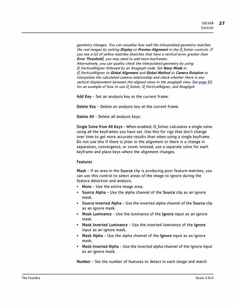
Add Key - Set an analysis key at the current frame.
Delete Key - Delete an analysis key at the current frame.
Delete All - Delete all analysis keys.
Single Solve from All Keys - When enabled, O_Solver calculates a single solve using all the keyframes you have set. Use this for rigs that don’t change over time to get more accurate results than when using a single keyframe. Do not use this if there is jitter in the alignment or there is a change in separation, convergence, or zoom. Instead, use a separate solve for each keyframe and place keys where the alignment changes.
Features
Mask - If an area in the Source clip is producing poor feature matches, you can use this control to select areas of the image to ignore during the feature detection and analysis.
• None - Use the entire image area.
• Source Alpha - Use the alpha channel of the Source clip as an ignore mask.
• Source Inverted Alpha - Use the inverted alpha channel of the Source clip as an ignore mask.
• Mask Luminance - Use the luminance of the Ignore input as an ignore mask.
• Mask Inverted Luminance - Use the inverted luminance of the Ignore input as an ignore mask.
• Mask Alpha - Use the alpha channel of the Ignore input as an ignore mask.
• Mask Inverted Alpha - Use the inverted alpha channel of the Ignore input as an ignore mask.
Number - Set the number of features to detect in each image and match
Ocula 3.0v3The Foundry
SOLVER 28Controls
between views.
Threshold - Set the threshold to select features in an image. Use a high value to select prominent points. Use a low value to spread features out across the image.
Separation - Set a required feature separation to force detected features to cover the image. It is important that the features do not cluster together. If you set Display to Keyframe Matches and see that this is the case, try increasing this value.
Display
Display - Change the display mode.
• Nothing - Only show the Source image.
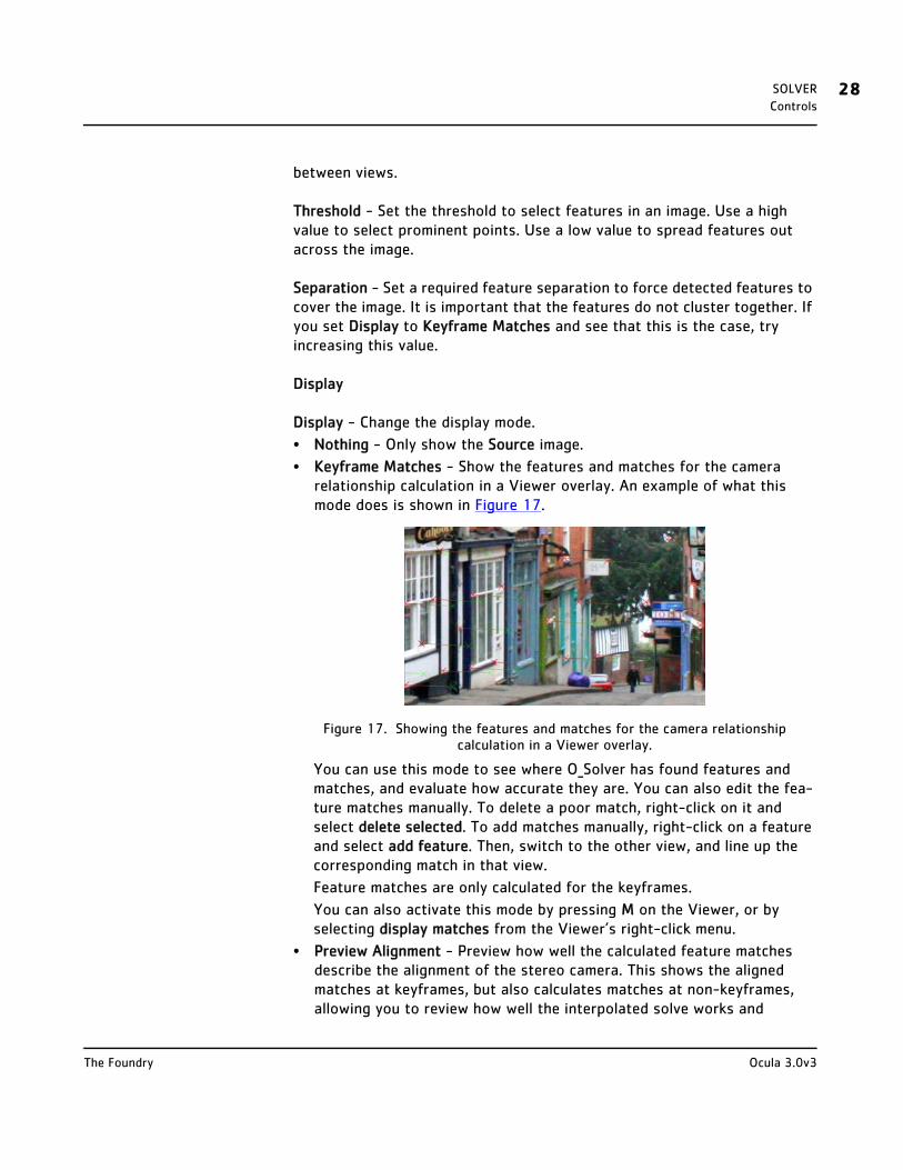
• Keyframe Matches - Show the features and matches for the camera relationship calculation in a Viewer overlay. An example of what this mode does is shown in Figure 17.
Figure 17. Showing the features and matches for the camera relationship calculation in a Viewer overlay.
You can use this mode to see where O_Solver has found features and matches, and evaluate how accurate they are. You can also edit the fea-ture matches manually. To delete a poor match, right-click on it and select delete selected. To add matches manually, right-click on a feature and select add feature. Then, switch to the other view, and line up the corresponding match in that view.
Feature matches are only calculated for the keyframes.
You can also activate this mode by pressing M on the Viewer, or by selecting display matches from the Viewer’s right-click menu.
• Preview Alignment - Preview how well the calculated feature matches describe the alignment of the stereo camera. This shows the aligned matches at keyframes, but also calculates matches at non-keyframes, allowing you to review how well the interpolated solve works and
Ocula 3.0v3The Foundry

SOLVER 29Controls
whether additional keyframes are required. If the lines between feature matches are horizontal, they describe the alignment of the camera rig well. If any lines are skewed (and displayed in yellow), you may want to delete the feature matches in question. If necessary, you can also add manual feature matches to replace them and preview the effect of the manual matches in the overlay. An example of what this mode does is shown in Figure 18.
Figure 18. Visualising the alignment of the calculated feature matches.
You can also activate this mode by pressing P on the Viewer, or by selecting preview alignment from the Viewer’s right-click menu.
Alignment Method - The alignment method to use to align the views when Display is set to Alignment.
• Vertical Skew - Align the features along the y axis using a skew. This does not move the features along the x axis.
• Perspective Warp - Do a four-corner warp on the images to align them on the y axis. This may move the features slightly along the x axis.
• Rotation - Align the features vertically by rotating the entire image around a point. The centre of the rotation is determined by the algorithm.
• Scale - Align the features vertically by scaling the image.
• Simple Shift - Align the features vertically by moving the entire image up or down.
• Scale Rotate - Align the features vertically by simultaneously scaling and rotating the entire image around a point. The centre of the rotation is determined by the algorithm.
• Camera Rotation - Align the features by first performing a 3D rotation of both cameras so that they have exactly the same orientation and a parallel viewing axis, and then reconverging the views to provide the original convergence. For best results, use the Camera input to provide the information for the shooting cameras.
Match Offset - The offset (in pixels) applied to the aligned feature matches.
Ocula 3.0v3The Foundry

SOLVER 30Controls
You can:
• increase this value to artificially increase the disparity, so it’s easier to see how horizontal the feature matches are. Any matches that aren’t horizontal can be considered poor matches and deleted manually.
• decrease this value to set the disparity of particular matches to zero and examine the vertical offset at each feature. The matches should sit on top of each other. If they are vertically offset, you know they’re poor and can delete them manually.
Figure 19. Accurate feature matches sit on top of each other (left), whereas poor matches are vertically offset (right).
The Match Offset control is only available when Display is set to Preview Alignment. You can also adjust it by pressing < or > on the Viewer, or by selecting decrease offset or increase offset from the Viewer’s right-click menu.
Error Threshold - Threshold on the vertical alignment error in pixels. When Display is set to Preview Alignment, any matches with a vertical error greater than the threshold are selected in the Viewer. This allows you to easily delete poor matches with large errors when previewing alignment at keyframes.
Current Frame
Re-analyse Frame - Clear the automatic feature matches from the current frame and recalculate them. This can be useful if there have been changes in the node tree upstream from O_Solver, you have deleted too many automatic feature matches, or you want to calculate the automatic matches based on any user matches you have created.
Delete User Matches - Delete all feature matches you have manually added to the current frame.
Ocula 3.0v3The Foundry

SOLVER 31Example
Example See page 41 for an example of how to use O_Solver and O_DisparityGenerator to calculate a disparity field for a stereo image.
Ocula 3.0v3The Foundry

DISPARITYGENERATOR
Description The O_DisparityGenerator plug-in is used to create disparity fields for stereo images. A disparity field maps the location of a pixel in one view to the location of its corresponding pixel in the other view. It includes two sets of disparity vectors: one maps the left view to the right, and the other maps the right view to the left.
The following Ocula plug-ins rely on disparity fields to produce their output:
• O_OcclusionDetector
• O_ColourMatcher (in 3D LUT and Local Matching modes)
• O_FocusMatcher
• O_VerticalAligner (in Local Alignment mode)
• O_NewView
• O_InteraxialShifter
• O_VectorGenerator
• O_DisparityToDepth, and
• O_DisparityViewer.
If you have more than one of these plug-ins in your node tree with one or more of the same inputs, they might well require identical disparity field calculations. O_DisparityGenerator is a utility plug-in designed to save processing time by allowing you to create the disparity fields separately, so that the results can then be reused by other Ocula plug-ins.
O_DisparityGenerator always requires an O_Solver node as one of its inputs to provide the alignment data for disparity matching. You can, however, control how much the disparity vectors respect O_Solver’s geometric alignment by using the Alignment slider in the O_DisparityGenerator controls.
The final disparity vectors are stored in disparity channels, so you might not see any image data appear when you first calculate the disparity field. To see the output inside Nuke, select a disparity channel from the channel set and channel controls in the top left corner of the Viewer. An example of what a disparity channel might look like is shown below.

DISPARITYGENERATOR 33Inputs
Figure 20. A disparity field.
In general, once you have generated a disparity field that describes the relation between the views of a particular clip well, it will be suitable for use in most of the Ocula plug-ins. We recommend that you insert a Write node after O_DisparityGenerator to render the original images and the disparity channels as a stereo .exr file (sometimes referred to as .sxr). This format allows for the storage of an image with multiple views and channel sets embedded in it. Later, whenever you use the same image sequence, the disparity field will be loaded into Nuke together with the sequence and is readily available for the Ocula plug-ins. For information on how to generate a disparity field and render it as an .exr file, see Quick Start below.
Tip O_DisparityGenerator operates on luminance images. If you, for example, have a bluescreen image where the background and foreground luminance are not that different, you may be able to improve the results by keying out the background before using O_DisparityGenerator.
If you have a CG scene with camera information and z-depth map available, you can also create disparity fields using the O_DepthToDisparity node. For more information, see DepthToDisparity on page 113.
Inputs O_DisparityGenerator has four inputs:
• Source - A stereo pair of images. The images should be followed by an O_Solver node, unless you’re using the Solver input.
• Solver - If the Source sequence doesn’t contain features that O_Solver is able to match well, you can use O_Solver on another sequence shot with the same camera setup. If you do so, connect O_Solver to this input.
• Ignore - An optional mask that specifies areas to exclude from the disparity calculation. You can use this input to prevent distortions at occlusions or to calculate disparity for a background layer by ignoring all foreground elements. Note that masks should exist in both views, and
Ocula 3.0v3The Foundry

DISPARITYGENERATOR 34Quick Start
O_DisparityGenerator expects alpha values of either 0 (for regions to use) or 1 (for regions to ignore).
• Fg - An optional mask that specifies the area to calculate disparity. You can use this to create a disparity layer for a foreground element. To create layers for different elements, use several O_DisparityGenerator nodes. If necessary, you can also use the Ignore mask to exclude elements in the foreground region. Note that masks should exist in both views, and O_DisparityGenerator expects alpha values of either 0 (for background) or 1 (for foreground).
To see a table listing the nodes or channels each Ocula node requires in its inputs, turn to Appendix B: Node Dependencies on page 155.
Quick Start To generate a disparity field for a stereo clip, do the following:
1. Start Nuke and press S on the Node Graph to open the project settings. Go to the Views tab and click the Set up views for stereo button.
2. From the Toolbar, select Image > Read to load your stereo clip into Nuke. If you don’t have both views in the same file, select Views > JoinViews to combine them, or use a variable in the Read node’s file field to replace the name of the view (use the variable %V to replace an entire view name, such as left or right, and %v to replace an initial letter, such as l or r). For more information, refer to the Nuke user guide.
Figure 21. The left view. Figure 22. An ignore mask for the left view. This ignores the foreground
elements to calculate disparity for the background.
Figure 23. The left view. Figure 24. A foreground mask for the left view.
Ocula 3.0v3The Foundry
DISPARITYGENERATOR 35Quick Start
3. Select Ocula > Ocula 3.0 > O_Solver to insert an O_Solver node after either the stereo clip or the JoinViews node (if you inserted one in the previous step). This plug-in calculates the geometrical relationship between the two views in the input clip. Set at least one keyframe.
For more instructions on how to use O_Solver, see Solver on page 18.
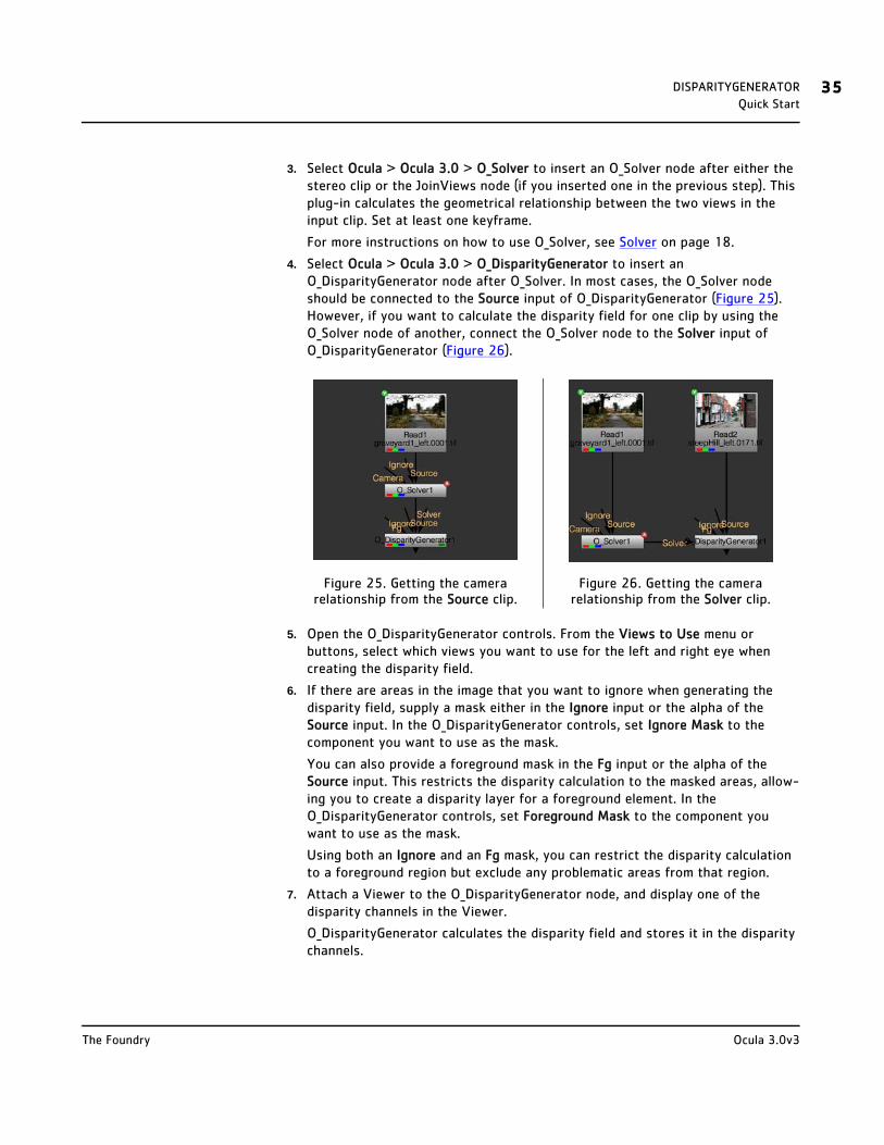
4. Select Ocula > Ocula 3.0 > O_DisparityGenerator to insert an O_DisparityGenerator node after O_Solver. In most cases, the O_Solver node should be connected to the Source input of O_DisparityGenerator (Figure 25). However, if you want to calculate the disparity field for one clip by using the O_Solver node of another, connect the O_Solver node to the Solver input of O_DisparityGenerator (Figure 26).
5. Open the O_DisparityGenerator controls. From the Views to Use menu or buttons, select which views you want to use for the left and right eye when creating the disparity field.
6. If there are areas in the image that you want to ignore when generating the disparity field, supply a mask either in the Ignore input or the alpha of the Source input. In the O_DisparityGenerator controls, set Ignore Mask to the component you want to use as the mask.
You can also provide a foreground mask in the Fg input or the alpha of the Source input. This restricts the disparity calculation to the masked areas, allow-ing you to create a disparity layer for a foreground element. In the O_DisparityGenerator controls, set Foreground Mask to the component you want to use as the mask.
Using both an Ignore and an Fg mask, you can restrict the disparity calculation to a foreground region but exclude any problematic areas from that region.
7. Attach a Viewer to the O_DisparityGenerator node, and display one of the disparity channels in the Viewer.
O_DisparityGenerator calculates the disparity field and stores it in the disparity channels.
Figure 25. Getting the camera relationship from the Source clip.
Figure 26. Getting the camera relationship from the Solver clip.
Ocula 3.0v3The Foundry

DISPARITYGENERATOR 36Quick Start
Figure 27. A disparity field.
8. If necessary, adjust the Sharpness control, which defines how distinct object boundaries should be in the calculated disparity field.
If you want to use the calculated disparity to rebuild images (using O_NewView, O_InteraxialShifter, O_FocusMatcher, or O_Retimer), set Sharpness to 0. This improves picture building.
If you want to use the calculated disparity to pick out layers in the scene, increase Sharpness to produce distinct object boundaries.
9. If you find that the disparity field is noisy in low-contrast image regions, try increasing the Noise value. This sets the amount of noise O_DisparityGenerator should ignore in the input footage when calculating the disparity field. The higher the value, the smoother the disparity field.
10. If necessary, you can use the Parallax Limits controls to cut off any spurious disparity vectors that are likely to be incorrect. To do so, look for features in the image that appear in front of the screen plane, switch between the two views, and locate the pixels that move the most (that is, have the largest disparity). Hover over those pixels in the Viewer and note their values on the x axis (in Figure 28, the value is 1560). Display the other view and do the same (in Figure 29, the value is 1423). The difference between these values (1423-1560) is the maximum negative parallax (-137). We can assume that any disparities that clearly exceed this maximum value are incorrect. If you enter the value in the Negative field and enable Enforce parallax limits,
O_DisparityGenerator cuts off any disparities that exceed the limit.
Figure 28. A pixel in the left view. Figure 29. The same pixel in the right view. The negative parallax here is:
1423-1560 = -137.
Ocula 3.0v3The Foundry
DISPARITYGENERATOR 37Quick Start
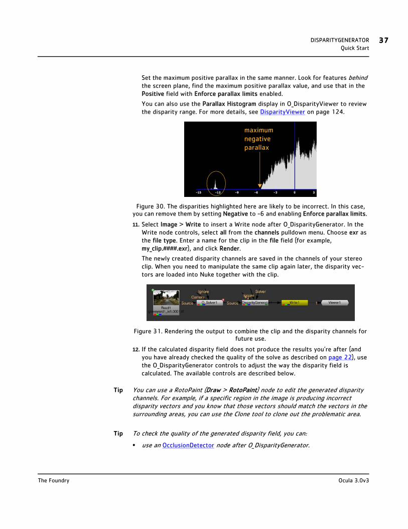
Set the maximum positive parallax in the same manner. Look for features behind the screen plane, find the maximum positive parallax value, and use that in the Positive field with Enforce parallax limits enabled.
You can also use the Parallax Histogram display in O_DisparityViewer to review the disparity range. For more details, see DisparityViewer on page 124.
Figure 30. The disparities highlighted here are likely to be incorrect. In this case, you can remove them by setting Negative to -6 and enabling Enforce parallax limits.
11. Select Image > Write to insert a Write node after O_DisparityGenerator. In the Write node controls, select all from the channels pulldown menu. Choose exr as the file type. Enter a name for the clip in the file field (for example, my_clip.####.exr), and click Render.
The newly created disparity channels are saved in the channels of your stereo clip. When you need to manipulate the same clip again later, the disparity vec-tors are loaded into Nuke together with the clip.
Figure 31. Rendering the output to combine the clip and the disparity channels for future use.
12. If the calculated disparity field does not produce the results you’re after (and you have already checked the quality of the solve as described on page 22), use the O_DisparityGenerator controls to adjust the way the disparity field is calculated. The available controls are described below.
Tip You can use a RotoPaint (Draw > RotoPaint) node to edit the generated disparity channels. For example, if a specific region in the image is producing incorrect disparity vectors and you know that those vectors should match the vectors in the surrounding areas, you can use the Clone tool to clone out the problematic area.
Tip To check the quality of the generated disparity field, you can:
• use an OcclusionDetector node after O_DisparityGenerator.
maximum negative parallax
Ocula 3.0v3The Foundry

DISPARITYGENERATOR 38Controls
• set Sharpness to 0 and use an O_NewView node after O_DisparityGenerator. In the O_NewView controls, if you set Inputs to Right and Interpolate Position to 0, the node uses pixels from the right view to build a new view on top of the left. You can then compare this new left view with the original left view in the Viewer. Where the views match, the generated disparity field is accurate. Where they differ, O_DisparityGenerator may be struggling to produce good results. For more information, see Example on page 41 and NewView on page 87.
Controls Views to Use - From the views that exist in your project settings, select the two views you want to use to create the disparity field. These views will be mapped for the left and right eye.
Ignore Mask - An optional mask that specifies areas to exclude from the disparity calculation. You can use this input to prevent distortions at occlusions or to calculate disparity for a background layer by ignoring all foreground elements. Note that masks should exist in both views, and O_DisparityGenerator expects alpha values of either 0 (for regions to use) or 1 (for regions to ignore).
• None - Do not use an ignore mask.
• Source Alpha - Use the alpha channel of the Source clip as an ignore mask.
• Source Inverted Alpha - Use the inverted alpha channel of the Source clip as an ignore mask.
• Mask Luminance - Use the luminance of the Ignore input as an ignore mask.
• Mask Inverted Luminance - Use the inverted luminance of the Ignore input as an ignore mask.
• Mask Alpha - Use the alpha channel of the Ignore input as an ignore mask.
• Mask Inverted Alpha - Use the inverted alpha channel of the Ignore input as an ignore mask.
Foreground Mask - An optional mask that specifies the area to calculate disparity. You can use this to create a disparity layer for a foreground element. To create layers for different elements, use several O_DisparityGenerator nodes. If necessary, you can also use the Ignore mask to exclude elements in the foreground region. Note that masks should exist in both views, and O_DisparityGenerator expects alpha values of either 0 (for background) or 1 (for foreground).
• None - Do not use a foreground mask.
• Source Alpha - Use the alpha channel of the Source clip as a foreground mask.
Ocula 3.0v3The Foundry
DISPARITYGENERATOR 39Controls
• Source Inverted Alpha - Use the inverted alpha channel of the Source clip as a foreground mask.
• Mask Luminance - Use the luminance of the Fg input as a foreground mask.
• Mask Inverted Luminance - Use the inverted luminance of the Fg input as a foreground mask.
• Mask Alpha - Use the alpha channel of the Fg input as a foreground mask.
• Mask Inverted Alpha - Use the inverted alpha channel of the Fg input as a foreground mask.
Noise - This sets the amount of noise O_DisparityGenerator should ignore in the input footage when calculating the disparity field. The higher the value, the smoother the disparity field. You may want to increase this value if you find that the disparity field is noisy in low-contrast image regions.
Strength - Sets the strength in matching pixels between the left and right views. Higher values allow you to accurately match similar pixels in one image to another, concentrating on detail matching even if the resulting disparity field is jagged. Lower values may miss local detail, but are less likely to provide you with the odd spurious vector, producing smoother results. Often, it is necessary to trade one of these qualities off against the other. You may want to increase this value to force the views to match, for example, where fine details are missed, or decrease it to smooth out the disparity field.
Consistency - This constrains the left and right disparities to be consistent. Increase the value to encourage the left and right disparity vectors to match.
Alignment - Sets how much to constrain the disparities to match the horizontal alignment defined by an upstream O_Solver node. A value of 0 calculates the disparity using unconstrained motion estimation. Increasing the value forces the disparities to be aligned. In most cases, you want this set to 0 or the default value of 0.1.
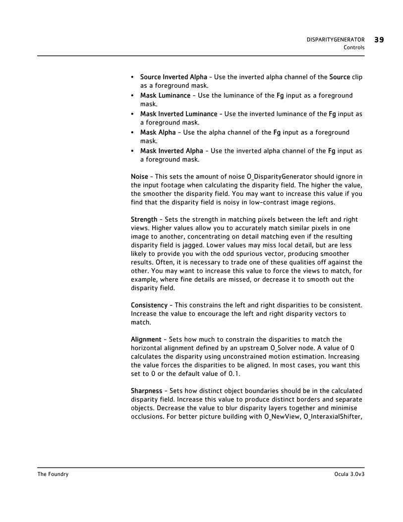
Sharpness - Sets how distinct object boundaries should be in the calculated disparity field. Increase this value to produce distinct borders and separate objects. Decrease the value to blur disparity layers together and minimise occlusions. For better picture building with O_NewView, O_InteraxialShifter,
Ocula 3.0v3The Foundry
DISPARITYGENERATOR 40Controls
O_FocusMatcher, and O_Retimer, you can set this value to 0.
Smoothness - Applies extra smoothing to the disparity field as a post process after image matching. The higher the value, the smoother the result. You can use this in conjunction with the Sharpness parameter to smooth out the disparity field separately for distinct objects in the shot.
Parallax Limits
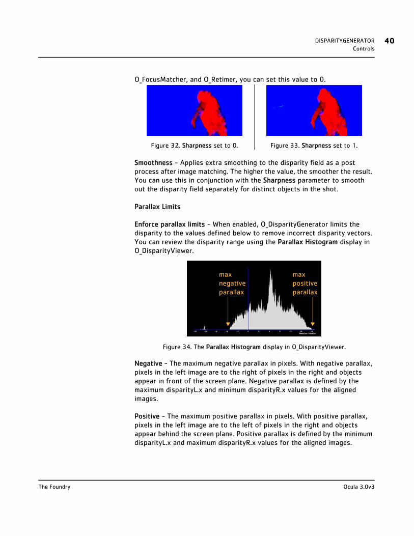
Enforce parallax limits - When enabled, O_DisparityGenerator limits the disparity to the values defined below to remove incorrect disparity vectors. You can review the disparity range using the Parallax Histogram display in O_DisparityViewer.
Figure 34. The Parallax Histogram display in O_DisparityViewer.
Negative - The maximum negative parallax in pixels. With negative parallax, pixels in the left image are to the right of pixels in the right and objects appear in front of the screen plane. Negative parallax is defined by the maximum disparityL.x and minimum disparityR.x values for the aligned images.
Positive - The maximum positive parallax in pixels. With positive parallax, pixels in the left image are to the left of pixels in the right and objects appear behind the screen plane. Positive parallax is defined by the minimum disparityL.x and maximum disparityR.x values for the aligned images.
Figure 32. Sharpness set to 0. Figure 33. Sharpness set to 1.
max negative parallax
max positive parallax
Ocula 3.0v3The Foundry
DISPARITYGENERATOR 41Example
Example In this example, we read in a stereo image, use O_Solver and O_DisparityGenerator to calculate its disparity field, and render the result as a single .exr file that contains the left and the right view and the newly created disparity channels. Later, whenever you use the same image, the disparity field will be loaded into Nuke together with the image. This makes the disparity field readily available for the other Ocula plug-ins, many of which need it to produce their output.
The stereo image used here can be downloaded from our web site. For more information, please see Example Images on page 6.
Step by Step Calculating the Camera Relationship
1. Start Nuke and press S on the Node Graph to open the project settings. Go to the Views tab and click the Set up views for stereo button.
2. Select Image > Read to import graveyard_left.tif. In the Read node controls, locate the file field. Then, replace the word left in the file name with the variable %V. This way, Nuke reads in both the left and the right view using the same Read node.
3. Select the Read node and choose Ocula > Ocula 3.0 > O_Solver from the Toolbar.
This inserts an O_Solver node after the stereo image. The purpose of this node is to define the geometrical relationship between the two views in the input image (that is, the camera relationship or solve). That information can then be fed to O_DisparityGenerator, which creates the final disparity field.
For now, we’ll concentrate on creating an accurate solve using O_Solver.
4. Attach a Viewer to the O_Solver node.
5. In the O_Solver controls, click Add Key to set a keyframe for O_Solver to analyse.
Our example here consists of just one frame, but if you were using a sequence, you should set keyframes wherever the camera setup changes. If the setup doesn’t change, you can get away with using just one keyframe. Remember that this should be a frame that is easy to match between views - ideally, a frame with enough picture detail, but no motion blur, occluding fog, or dust.
Every time you add a keyframe, O_Solver analyses the footage and calculates the solve.
6. Set Display to Keyframe Matches (or press M on the Viewer) and make sure you are viewing the keyframe.
The calculated feature matches are displayed in a Viewer overlay, and you can switch between views to compare them.
The views we set up in the project settings dictate the colour of the features in the overlay. Because we used the default settings in step 1, red indicates a fea-ture in the left view and green a feature in the right view.
Ocula 3.0v3The Foundry

DISPARITYGENERATOR 42Example
Figure 35. Display set to Keyframe Matches.
7. Now, set Display to Preview Alignment (or press P on the Viewer). This allows you to check the quality of your solve by previewing the alignment of the calculated feature matches in the Viewer. Ideally, the lines should all be horizontal. If they have a vertical error greater than Error Threshold, they are considered poor matches and displayed in yellow. At the moment, we have no poor matches.
8. We are going to be very picky here, so set Error Threshold to 3.
A few matches turn yellow, which means they are pre-selected in the Viewer.
9. Right-click on the Viewer and select delete selected (or simply press backspace) to delete all the matches displayed in yellow.
Figure 36. Deleting poor matches.
10. Press < (in other words, Shift+,) on the Viewer to decrease the Match Offset value gradually until some matches have no horizontal offset. This sets the
Ocula 3.0v3The Foundry
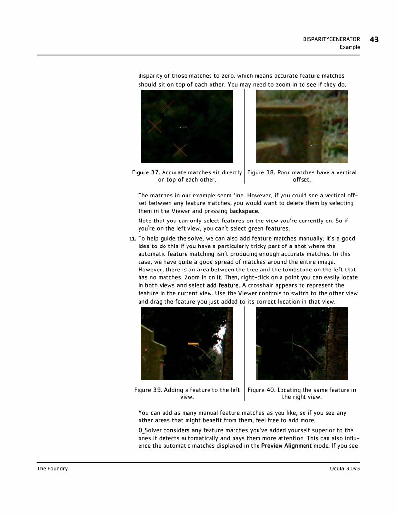
DISPARITYGENERATOR 43Example
disparity of those matches to zero, which means accurate feature matches
should sit on top of each other. You may need to zoom in to see if they do.
The matches in our example seem fine. However, if you could see a vertical off-set between any feature matches, you would want to delete them by selecting them in the Viewer and pressing backspace.
Note that you can only select features on the view you’re currently on. So if you're on the left view, you can't select green features.
11. To help guide the solve, we can also add feature matches manually. It’s a good idea to do this if you have a particularly tricky part of a shot where the automatic feature matching isn’t producing enough accurate matches. In this case, we have quite a good spread of matches around the entire image. However, there is an area between the tree and the tombstone on the left that has no matches. Zoom in on it. Then, right-click on a point you can easily locate in both views and select add feature. A crosshair appears to represent the feature in the current view. Use the Viewer controls to switch to the other view
and drag the feature you just added to its correct location in that view.
You can add as many manual feature matches as you like, so if you see any other areas that might benefit from them, feel free to add more.
O_Solver considers any feature matches you’ve added yourself superior to the ones it detects automatically and pays them more attention. This can also influ-ence the automatic matches displayed in the Preview Alignment mode. If you see
Figure 37. Accurate matches sit directly on top of each other.
Figure 38. Poor matches have a vertical offset.
Figure 39. Adding a feature to the left view.
Figure 40. Locating the same feature in the right view.
Ocula 3.0v3The Foundry

DISPARITYGENERATOR 44Example
any automatic matches that don't agree with the alignment defined by the matches you added, delete them as described earlier.
12. Once you’re happy with the solve, set Display back to Nothing and proceed to Generating the Disparity Field below.
Generating the Disparity Field
1. Select Ocula > Ocula 3.0 > O_DisparityGenerator to insert an O_DisparityGenerator node after O_Solver.
Figure 41. The node tree with O_DisparityGenerator.
2. Use the Sharpness slider to set how distinct object boundaries should be in the
calculated disparity field:
• If you want to use the generated disparity field to rebuild images (using O_NewView, O_InteraxialShifter, O_FocusMatcher, or O_Retimer), set Sharpness to 0. This improves picture building.
• If you want to pick out distinct disparity layers in the scene, increase Sharp-ness to 1.
For the purposes of this example, leave Sharpness set to 0.
3. Display one of the disparity channels by selecting it from the channel set and channel menus in the upper left corner of the Viewer.
O_DisparityGenerator calculates the disparity field. You will probably see some-thing colourful and seemingly unreadable, much like the image in Figure 42. Don’t worry - that’s what the disparity channels are supposed to look like.
Figure 42. The calculated disparity field.
4. You now have a disparity field, but it can be hard to tell if it’s accurate just by looking at it. This is where the O_NewView node can help. Select Ocula > Ocula 3.0 > O_NewView to add it after O_DisparityGenerator.
Ocula 3.0v3The Foundry

DISPARITYGENERATOR 45Example
This node uses the disparity field to produce its results. If the results seem accurate, we can assume that the disparity field is accurate too.
5. In the O_NewView controls, set Inputs to Right and Interpolate Position to 0.
This tells the node to use pixels from the right view to build a new view on top of the left. You can then compare this new left view with the original left view.
6. In the Viewer controls, select rgba to display the colour channels again.
7. Select the Read node and press 2 to connect it to the Viewer. Your node tree should now look like this:
Figure 43. The Viewer here has two inputs: 1) the O_NewView node with the newly generated left view and 2) the Read node with the original left view.
8. Hover over the Viewer and press 1 and 2 to switch between the newly generated left view and the original left view. Where the views match, the generated disparity field is accurate. Where they differ, O_DisparityGenerator may be struggling to produce good results.
In this case, O_DisparityGenerator has done a pretty good job. There’s a black strip on the left and some changes in the areas around the tree and some of the gravestones, but these are caused by occlusions in the scene rather than a poor disparity field. Building a new view in these occluded regions isn’t possible, so
we can be reasonably happy with the results.
9. Delete the O_NewView node from the script. We no longer need it, as we were only using it to check the quality of our disparity field. You can also disconnect the Read node from the Viewer.
10. Select Image > Write to insert a Write node between the O_DisparityGenerator and the Viewer. Your node tree should now look like the one in Figure 46.
Figure 44. The original left view. Figure 45. The new left view generated using the disparity field.
Ocula 3.0v3The Foundry
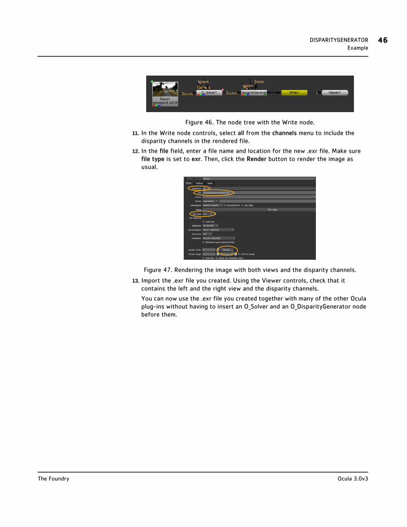
DISPARITYGENERATOR 46Example
Figure 46. The node tree with the Write node.
11. In the Write node controls, select all from the channels menu to include the disparity channels in the rendered file.
12. In the file field, enter a file name and location for the new .exr file. Make sure file type is set to exr. Then, click the Render button to render the image as usual.
Figure 47. Rendering the image with both views and the disparity channels.
13. Import the .exr file you created. Using the Viewer controls, check that it contains the left and the right view and the disparity channels.
You can now use the .exr file you created together with many of the other Ocula plug-ins without having to insert an O_Solver and an O_DisparityGenerator node before them.
Ocula 3.0v3The Foundry

OCCLUSIONDETECTOR
Description O_OcclusionDetector generates a mask for the occluded pixels in each view: that is, pixels visible in one view but not the other.
An occlusion mask identifies areas that are likely to be incorrect when using disparity to match one view to another. You can use it to quality check the result of O_DisparityGenerator and to identify at a glance image regions that are likely to fail when using the Ocula nodes that rely on rebuilding one view from the other (after all, if the pixel information isn’t there in one view, it cannot be generated for the other). Once you know which areas aren’t suitable for picture building, you can choose how to handle those areas in order to get a better result.
You may want to generate an occlusion mask for each view when using the following nodes:
• FocusMatcher - This node requires an occlusion mask upstream to produce its output if Primary Method is set to Rebuild.
• ColourMatcher - This node requires an occlusion mask upstream to produce its output if Mode is set to either 3D LUT or Local Matching.
• DisparityGenerator - This node does NOT require an occlusion mask, but you can use one downstream to quality check the generated disparity field.
• NewView, InteraxialShifter, and Retimer - These nodes do NOT require an occlusion mask to produce their output, but if you like, you can use one upstream to preview where they may struggle to generate a new view.
The final occlusion masks for each view are stored in the mask_occlusion channel. You can view them in Nuke by setting the alpha channel menu to
Figure 48. The left view of a stereo image.
Figure 49. The occlusion mask generated for the left view (pixels occluded in the
left view).

OCCLUSIONDETECTOR 48Inputs
mask_occlusion.alpha and pressing M on the Viewer. This superimposes the occlusion mask for the current view as a red overlay on top of the image’s RGB channels as shown in Figure 50.
Figure 50. An occlusion mask displayed on top of the colour channels.
Once you have generated an occlusion mask, you can use a Write node to render the mask into the channels of your stereo EXR file along with the colour and disparity channels. Later, whenever you use the same image sequence, the occlusion mask will be loaded into Nuke together with the sequence.
Like most other Ocula plug-ins, O_OcclusionDetector needs upstream disparity channels to produce its output. For an in-depth explanation of how to create disparity channels, refer to the Solver and DisparityGenerator chapters.
Inputs O_OcclusionDetector has one input:Source - A stereo pair of images. If disparity channels aren’t embedded in the images, you should add an O_Solver and an O_DisparityGenerator node after the image sequence.
To see a table listing the nodes or channels each Ocula node requires in its inputs, turn to Appendix B: Node Dependencies on page 155.
Quick Start To generate an occlusion mask, do the following:
mask_occlusion.alpha
Ocula 3.0v3The Foundry
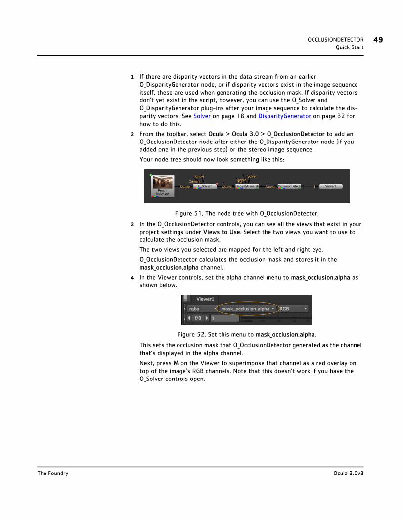
OCCLUSIONDETECTOR 49Quick Start
1. If there are disparity vectors in the data stream from an earlier O_DisparityGenerator node, or if disparity vectors exist in the image sequence itself, these are used when generating the occlusion mask. If disparity vectors don’t yet exist in the script, however, you can use the O_Solver and O_DisparityGenerator plug-ins after your image sequence to calculate the dis-parity vectors. See Solver on page 18 and DisparityGenerator on page 32 for how to do this.
2. From the toolbar, select Ocula > Ocula 3.0 > O_OcclusionDetector to add an O_OcclusionDetector node after either the O_DisparityGenerator node (if you added one in the previous step) or the stereo image sequence.
Your node tree should now look something like this:
Figure 51. The node tree with O_OcclusionDetector.
3. In the O_OcclusionDetector controls, you can see all the views that exist in your project settings under Views to Use. Select the two views you want to use to calculate the occlusion mask.
The two views you selected are mapped for the left and right eye.
O_OcclusionDetector calculates the occlusion mask and stores it in the mask_occlusion.alpha channel.
4. In the Viewer controls, set the alpha channel menu to mask_occlusion.alpha as shown below.
Figure 52. Set this menu to mask_occlusion.alpha.
This sets the occlusion mask that O_OcclusionDetector generated as the channel that’s displayed in the alpha channel.
Next, press M on the Viewer to superimpose that channel as a red overlay on top of the image’s RGB channels. Note that this doesn’t work if you have the O_Solver controls open.
Ocula 3.0v3The Foundry

OCCLUSIONDETECTOR 50Quick Start
Figure 53. The red overlay indicates occluded regions where picture building operations are likely to fail.
5. If necessary, adjust the following controls and observe their effect on the occlusion mask:
• Depth Occlusions sets the threshold for marking occlusions at depth changes (that is, where there is a sharp change in disparity). Increase this value to flag more areas as occluded. Try using a value of 0.3 or 0.5 where there are
extreme occlusions in the image.
• Colour Threshold sets the threshold for marking occlusions at colour differ-ences between views (that is, where the image content is different between the views). Decrease this value to flag more areas as occluded. Try using a value of 0.02 to pick up more occlusions if the colour variation in the image is flat. Try increasing the value to 0.1 if there are a lot of highly textured regions, such as
foliage.
Figure 54. Depth Occlusions = 0.1. Figure 55. Depth Occlusions = 0.5.
Figure 56. Colour Threshold = 0.005. Figure 57. Colour Threshold = 0.02.
Ocula 3.0v3The Foundry
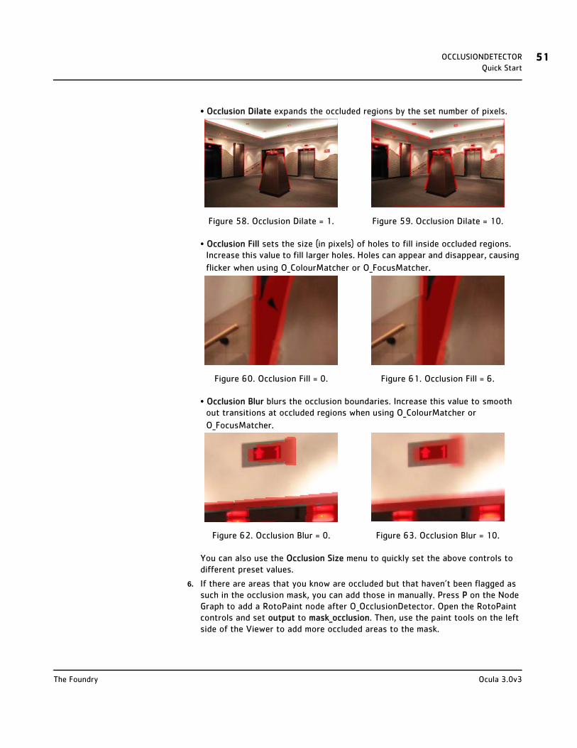
OCCLUSIONDETECTOR 51Quick Start
• Occlusion Dilate expands the occluded regions by the set number of pixels.
• Occlusion Fill sets the size (in pixels) of holes to fill inside occluded regions. Increase this value to fill larger holes. Holes can appear and disappear, causing
flicker when using O_ColourMatcher or O_FocusMatcher.
• Occlusion Blur blurs the occlusion boundaries. Increase this value to smooth out transitions at occluded regions when using O_ColourMatcher or
O_FocusMatcher.
You can also use the Occlusion Size menu to quickly set the above controls to different preset values.
6. If there are areas that you know are occluded but that haven’t been flagged as such in the occlusion mask, you can add those in manually. Press P on the Node Graph to add a RotoPaint node after O_OcclusionDetector. Open the RotoPaint controls and set output to mask_occlusion. Then, use the paint tools on the left side of the Viewer to add more occluded areas to the mask.
Figure 58. Occlusion Dilate = 1. Figure 59. Occlusion Dilate = 10.
Figure 60. Occlusion Fill = 0. Figure 61. Occlusion Fill = 6.
Figure 62. Occlusion Blur = 0. Figure 63. Occlusion Blur = 10.
Ocula 3.0v3The Foundry

OCCLUSIONDETECTOR 52Controls
7. Of course, you can also use RotoPaint to paint out regions that are incorrectly marked as occluded.
8. When you’re happy with the results, press M on the Viewer again to return to the RGB display.
9. If you like, you can add a Write node after O_OcclusionDetector and render the colour channels, disparity channels, and occlusion mask into the channels of a stereo EXR file.
Later, whenever you use the same image sequence, the occlusion mask will be loaded into Nuke together with the sequence. If necessary, you can use a Roto-Paint node to edit the occlusions for use with O_FocusMatcher or O_ColourMatcher, or simply replace them using another O_OcclusionDetector to adjust the mask on the fly.
Controls Views to Use - From the views that exist in your project settings, select the two views you want to use to generate an occlusion mask. These views will be mapped for the left and right eye.
Depth Occlusions - The threshold for marking occlusions at depth changes (that is, where there is a sharp change in disparity). Increase this value to flag more areas as occluded. Try using a value of 0.3 or 0.5 where there are extreme occlusions in the image.
Colour Threshold - The threshold for marking occlusions at colour differences between views (that is, where the image content is different between the views). Decrease this value to flag more areas as occluded. Try using a value of 0.02 to pick up more occlusions if the colour variation in the image is flat. Try increasing the value to 0.1 if there are a lot of highly textured regions, such as foliage.
Refinement Options
Occlusion Size - Presets for different occlusions sizes. Selecting the size of the regions that are visible in one view but not the other here sets the Occlusion Dilate, Occlusion Fill, and Occlusion Blur controls accordingly. The default is Small, but if there is a lot of parallax in the images, there can be a lot of image content occluded or revealed between views so you can switch to Large or Extreme to create larger occlusion regions.
• Small
• Medium
• Large
• Extreme
Ocula 3.0v3The Foundry
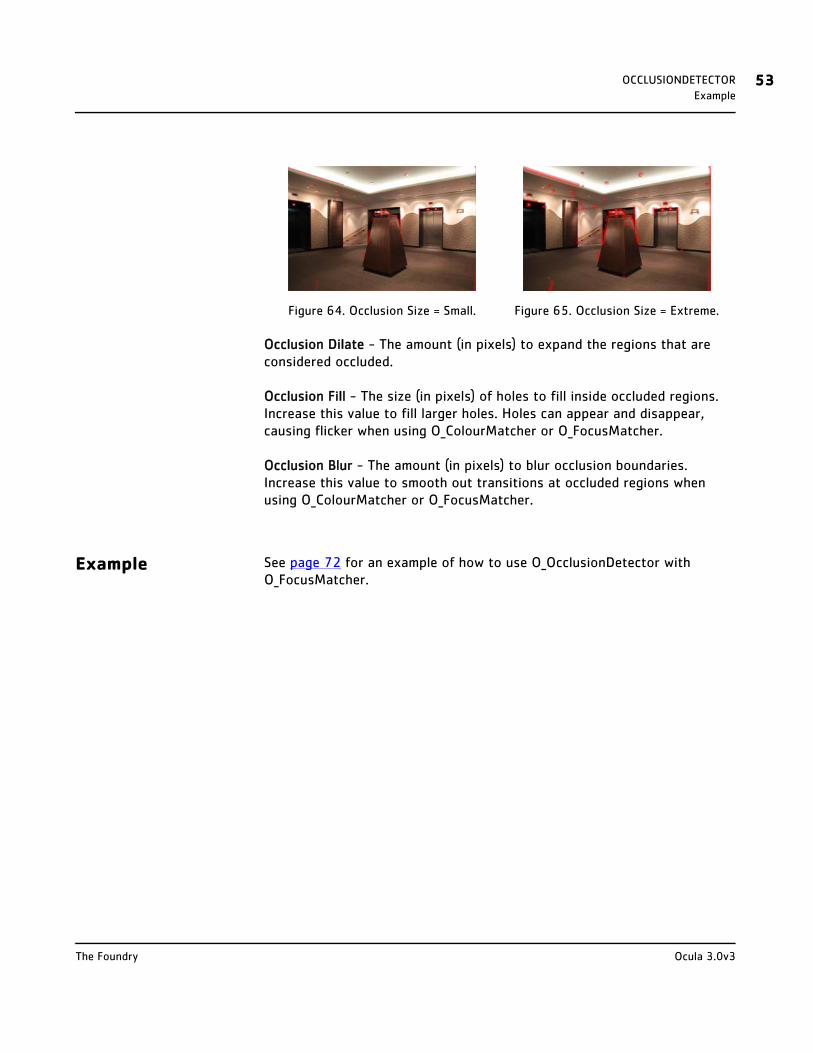
OCCLUSIONDETECTOR 53Example
Occlusion Dilate - The amount (in pixels) to expand the regions that are considered occluded.
Occlusion Fill - The size (in pixels) of holes to fill inside occluded regions. Increase this value to fill larger holes. Holes can appear and disappear, causing flicker when using O_ColourMatcher or O_FocusMatcher.
Occlusion Blur - The amount (in pixels) to blur occlusion boundaries. Increase this value to smooth out transitions at occluded regions when using O_ColourMatcher or O_FocusMatcher.
Example See page 72 for an example of how to use O_OcclusionDetector with O_FocusMatcher.
Figure 64. Occlusion Size = Small. Figure 65. Occlusion Size = Extreme.
Ocula 3.0v3The Foundry
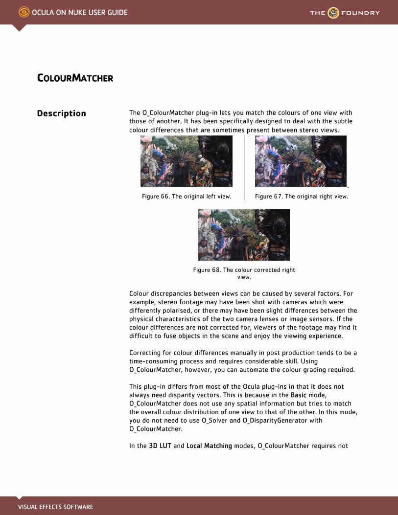
COLOURMATCHER
Description The O_ColourMatcher plug-in lets you match the colours of one view with those of another. It has been specifically designed to deal with the subtle colour differences that are sometimes present between stereo views.
Colour discrepancies between views can be caused by several factors. For example, stereo footage may have been shot with cameras which were differently polarised, or there may have been slight differences between the physical characteristics of the two camera lenses or image sensors. If the colour differences are not corrected for, viewers of the footage may find it difficult to fuse objects in the scene and enjoy the viewing experience.
Correcting for colour differences manually in post production tends to be a time-consuming process and requires considerable skill. Using O_ColourMatcher, however, you can automate the colour grading required.
This plug-in differs from most of the Ocula plug-ins in that it does not always need disparity vectors. This is because in the Basic mode, O_ColourMatcher does not use any spatial information but tries to match the overall colour distribution of one view to that of the other. In this mode, you do not need to use O_Solver and O_DisparityGenerator with O_ColourMatcher.
In the 3D LUT and Local Matching modes, O_ColourMatcher requires not
.
Figure 66. The original left view. Figure 67. The original right view.
Figure 68. The colour corrected right view.
COLOURMATCHER 55Inputs
only a disparity field but also an occlusion mask upstream. You can generate a disparity field and an occlusion mask using Solver, DisparityGenerator, and OcclusionDetector.
Inputs O_ColourMatcher has two inputs:
• Source - A stereo pair of images.
If disparity channels and occlusion masks aren’t embedded in the images and you are using the 3D LUT or Local Matching mode, you should use an O_Solver, an O_DisparityGenerator, and an OcclusionDetector node after the image sequence.
• Mask - An optional mask that determines where to take the colour distribution from. For example, if you have a clip showing a person in front of a green screen, you might want to use a mask to exclude the green area so the plug-in concentrates on matching the person.
In the Basic and 3D LUT modes, O_ColourMatcher calculates the trans-form on the masked area of the source view but applies it to the whole of the view it's correcting. In the Local Matching mode, it calculates the transform on the masked area and applies it to that area only.
To see a table listing the nodes or channels each Ocula node requires in its inputs, turn to Appendix B: Node Dependencies on page 155.
Quick Start You can match the colours of one view with those of another using three different algorithms:
• Basic - This mode takes the colour distribution of one entire view and modifies that to match the distribution of the other view. See Basic Mode.
• 3D LUT - This mode generates a global look-up table (LUT) from local matches at unoccluded pixels. You can export the LUT calculated for the current frame in .vf format. This allows you to apply the LUT separately using Nuke’s Vectorfield (Color > 3D LUT > Vectorfield) node. See 3D LUT Mode.
• Local Matching - This mode first divides the two images into square blocks according to the Block Size control. Then, it matches the colour distributions between corresponding blocks in the two views. This can be useful if there are local colour differences between the views, such as highlights that are brighter in one view than the other. See Local Matching Mode.
Ocula 3.0v3The Foundry

COLOURMATCHER 56Quick Start
Basic Mode 1. Select Ocula > Ocula 3.0 > O_ColourMatcher to insert an O_ColourMatcher node after your stereo clip.
2. Connect a Viewer to the O_ColourMatcher node.
Figure 69. O_ColourMatcher node tree.
3. In the O_ColourMatcher controls, you can see all the views that exist in your project settings under Views to Use. Select the two views you want to match.
The two views you selected are mapped for the left and right eye.
4. From the Match menu, select if you want to adjust the colours of the left view to match them with those of the right, or vice versa.
5. If there are areas in the image that you want to ignore when calculating the colour transformation, supply a mask either in the Mask input or the alpha of the Source input. In the O_ColourMatcher controls, set Mask Component to the component you want to use as the mask.
6. If you are not happy with the results, try one of the other modes described below.
3D LUT Mode 1. Make sure there are disparity vectors in the data stream from an earlier O_DisparityGenerator node, or disparity vectors exist in the image sequence itself. If disparity vectors don’t yet exist in the script, you can use the O_Solver and O_DisparityGenerator plug-ins after your image sequence to calculate the disparity vectors. See Solver on page 18 and DisparityGenerator on page 32 for how to do this.
2. If an occlusion mask doesn’t yet exist in the data stream or the image sequence itself, use an O_OcclusionDetector node to create one. See OcclusionDetector on page 47.
You can also replace an existing occlusion mask by inserting a new O_OcclusionDetector before O_ColourMatcher. This allows you to modify the occlusions.
3. Select Ocula > Ocula 3.0 > O_ColourMatcher to insert an O_ColourMatcher node after your stereo clip.
4. Connect a Viewer to the O_ColourMatcher node.
Figure 70. O_ColourMatcher node tree.
Ocula 3.0v3The Foundry
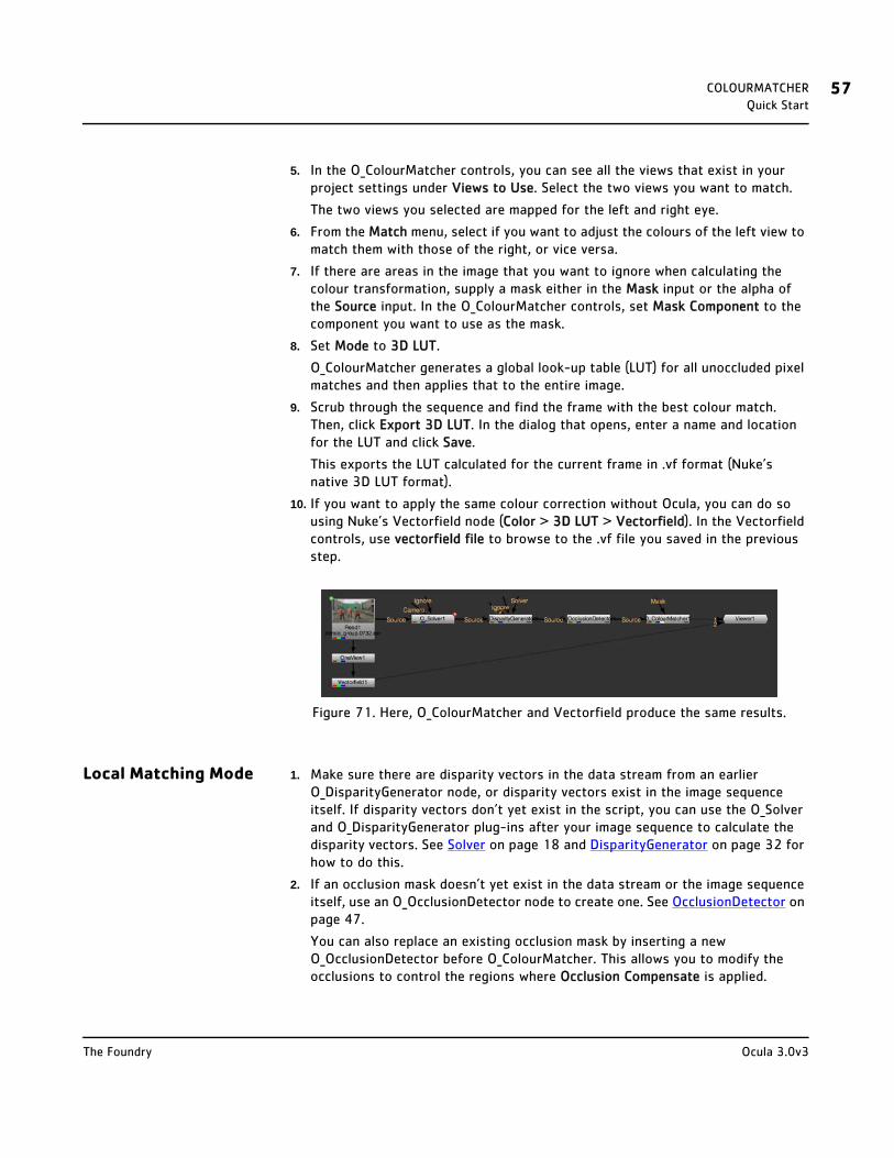
COLOURMATCHER 57Quick Start
5. In the O_ColourMatcher controls, you can see all the views that exist in your project settings under Views to Use. Select the two views you want to match.
The two views you selected are mapped for the left and right eye.
6. From the Match menu, select if you want to adjust the colours of the left view to match them with those of the right, or vice versa.
7. If there are areas in the image that you want to ignore when calculating the colour transformation, supply a mask either in the Mask input or the alpha of the Source input. In the O_ColourMatcher controls, set Mask Component to the component you want to use as the mask.
8. Set Mode to 3D LUT.
O_ColourMatcher generates a global look-up table (LUT) for all unoccluded pixel matches and then applies that to the entire image.
9. Scrub through the sequence and find the frame with the best colour match. Then, click Export 3D LUT. In the dialog that opens, enter a name and location for the LUT and click Save.
This exports the LUT calculated for the current frame in .vf format (Nuke’s native 3D LUT format).
10. If you want to apply the same colour correction without Ocula, you can do so using Nuke’s Vectorfield node (Color > 3D LUT > Vectorfield). In the Vectorfield controls, use vectorfield file to browse to the .vf file you saved in the previous step.
Figure 71. Here, O_ColourMatcher and Vectorfield produce the same results.
Local Matching Mode 1. Make sure there are disparity vectors in the data stream from an earlier O_DisparityGenerator node, or disparity vectors exist in the image sequence itself. If disparity vectors don’t yet exist in the script, you can use the O_Solver and O_DisparityGenerator plug-ins after your image sequence to calculate the disparity vectors. See Solver on page 18 and DisparityGenerator on page 32 for how to do this.
2. If an occlusion mask doesn’t yet exist in the data stream or the image sequence itself, use an O_OcclusionDetector node to create one. See OcclusionDetector on page 47.
You can also replace an existing occlusion mask by inserting a new O_OcclusionDetector before O_ColourMatcher. This allows you to modify the occlusions to control the regions where Occlusion Compensate is applied.
Ocula 3.0v3The Foundry

COLOURMATCHER 58Quick Start
3. Select Ocula > Ocula 3.0 > O_ColourMatcher to insert an O_ColourMatcher node after your stereo clip.
4. Connect a Viewer to the O_ColourMatcher node.
Figure 72. O_ColourMatcher node tree.
5. In the O_ColourMatcher controls, you can see all the views that exist in your project settings under Views to Use. Select the two views you want to match.
The two views you selected are mapped for the left and right eye.
6. From the Match menu, select if you want to adjust the colours of the left view to match them with those of the right, or vice versa.
7. If there are areas in the image that you want to ignore when calculating the colour transformation, supply a mask either in the Mask input or the alpha of the Source input. In the O_ColourMatcher controls, set Mask Component to the component you want to use as the mask.
8. Set Mode to Local Matching.
In this mode, O_ColourMatcher first divides the two images into square blocks according to the Block Size control. Then, it matches the colour distributions between corresponding blocks in the two views.
9. Make sure Occlusion Compensate is enabled.
This allows O_ColourMatcher to produce better results in the occluded areas defined by the upstream occlusion mask. In these areas, O_ColourMatcher can-not correct the colour in one view by using the colour from the other. Instead, it looks for similar colours in the nearby unoccluded areas that it has already been able to match and uses the closest colour it finds.
10. Review the results. If you can see areas where the colour match is wrong, make sure they are included in the upstream occlusion mask. You can add them to the mask by:
• adjusting O_OcclusionDetector controls or
• using a RotoPaint node before O_ColourMatcher and painting into the mask_occlusion channel.
11. If you’re still not happy with the results, try adjusting:
• Block Size - The width and height (in pixels) of the square blocks that the images are divided into when calculating the colour match. Decrease this to create more localised colour updates near colour boundaries to prevent colour bleeding or halo artefacts.
• Colour Sigma - The amount of blurring across edges in the colour match at occluded regions. Decrease this to restrict the colour correction in occluded regions to similar colours. Increase the value to blur the colour correction.
• Region Size - The size of the region (in pixels) of unoccluded pixels used to calculate the colour correction at an occluded pixel. When Occlusion Compen-
Ocula 3.0v3The Foundry

COLOURMATCHER 59Controls
sate is enabled, O_ColourMatcher first finds the closest unoccluded pixel and then expands that distance by this number of pixels to pick up unoccluded pix-els to use.
• Edge Occlusions - The threshold for treating image edges as occlusions to reduce haloing and edge flicker. The higher the value, the more image edges are considered occlusions even if they aren’t marked as such in the upstream occlusion mask.
Controls Views to Use - From the views that exist in your project settings, select the two views whose colours you want to match. These views will be mapped for the left and right eye.
Match - Select how to match the colours.
• Left to Right - Adjust the colours of the left view to match with those of the right.
• Right to Left - Adjust the colours of the right view to match with those of the left.
Mode - The algorithm to use for the colour matching.
• Basic - This mode takes the colour distribution of one entire view and modifies that to match the distribution of the other view.
• 3D LUT - This mode generates a global look-up table (LUT) from local matches at unoccluded pixels. Note that this mode requires that there is a disparity field and an occlusion mask in the input data stream. If these don’t yet exist, you can create them using the O_Solver (see page 18), O_DisparityGenerator (see page 32), and OcclusionDetector (see page 47) plug-ins.
• Local Matching - This mode first divides the two images into square blocks according to the Block Size control. Then, it matches the colour distributions between corresponding blocks in the two views. This can be useful if there are local colour differences between the views, such as highlights that are brighter in one view than the other. Note that this mode requires that there is a disparity field in the input data stream. If there isn’t, you can create one using the O_Solver (see page 18) and O_DisparityGenerator (see page 32) plug-ins.
If Occlusion Compensate is enabled, this mode also requires an occlusion mask upstream. If one doesn’t exist, you can use O_OcclusionDetector (see OcclusionDetector) to create one.
Export 3D LUT - Export the colour change calculated for the current frame as a 3D look-up table (LUT) in .vf format. This allows you to apply the LUT separately using Nuke’s Vectorfield (Color > 3D LUT > Vectorfield) node.
Ocula 3.0v3The Foundry

COLOURMATCHER 60Controls
This control is only available in the 3D LUT mode.
Local Matching Options
Block Size - This control is only available in the Local Matching mode. It defines the width and height (in pixels) of the square blocks that the images are divided into when calculating the colour match.
Occlusion Compensate - Where there are occlusions in the image, O_ColourMatcher usually cannot correct the colour in one view by using the colour from the other. When Occlusion Compensate is enabled, it instead looks for similar colours in the nearby unoccluded areas that it has already been able to match and uses the closest colour it finds. This requires an occlusion mask upstream (you can create one using O_OcclusionDetector) and is only available in the Local Matching mode.
Edge Occlusions - The threshold for treating image edges as occlusions to reduce haloing and edge flicker. The higher the value, the more image edges are considered occlusions even if they aren’t marked as such in the upstream occlusion mask. This control is only available when Occlusion Compensate is enabled.
Colour Sigma - The amount of blurring across edges in the colour match at occluded regions. Decrease this to restrict the colour correction in occluded regions to similar colours. Increase the value to blur the colour correction. This control is only available when Occlusion Compensate is enabled.
Region Size - The size of the region (in pixels) of unoccluded pixels used to calculate the colour correction at an occluded pixel. When Occlusion Compensate is enabled, O_ColourMatcher first finds the closest unoccluded pixel and then expands that distance by this number of pixels to pick up unoccluded pixels to use.
Multi-scale Options
Number of Samples - The number of samples in the Local Matching mode. Using a value larger than 1 calculates the correction for multiple block sizes - between Block Size and Max Block Size - and then blends the results together. This can help to reduce errors.
Max Block Size - The size (in pixels) of the maximum block size to go up to when using multiple samples in the Local Matching mode. This control is only available if you have set Mode to Local Matching and Number of Samples to a value larger than 1.
Ocula 3.0v3The Foundry

COLOURMATCHER 61Controls
Sample Spacing - The type of sampling intervals to use when using multiple samples in the Local Matching mode.
• Uniform - The sampling interval remains constant. The samples are spaced evenly.
• Favour Small Block Sizes - The sampling interval increases as the block size increases. This weights the correction towards smaller block sizes, which preserve more detail, while still including some larger block sizes, which are more immune to disparity errors.
Colour Correction Type - In the Local Matching mode, O_ColourMatcher divides the two views into square blocks and matches the colour distributions between corresponding blocks. If you have set Number of Samples to a value larger than 1, it does this for multiple block sizes and then combines the results for different block sizes together. The Colour Correction Type control lets you choose how this is done.
• Minimum Correction - Out of the results you have, this picks the smallest correction at each point (that is, closest to your original image). This option can be useful if you have a very poor disparity map.
• Best Guess - Out of the results you have, this picks the closest correction to the target image at each point. The target image is created by using the disparity field to warp the other view onto the image you're trying to correct. This option can be useful if you have a very good disparity map.
• Average Correction - Use the mean value of the colour correction at each point. This option is the default.
Mask Options
Mask Component - Select the channel to use as a mask when calculating the colour transformation.
• None - Use the entire image area.
• Source Alpha - Use the alpha channel of the Source clip as a mask.
• Source Inverted Alpha - Use the inverted alpha channel of the Source clip as a mask.
• Mask Luminance - Use the luminance of the Mask input as a mask.
• Mask Inverted Luminance - Use the inverted luminance of the Mask input as a mask.
• Mask Alpha - Use the alpha channel of the Mask input as a mask.
• Mask Inverted Alpha - Use the inverted alpha channel of the Mask input as a mask.
Ocula 3.0v3The Foundry

COLOURMATCHER 62Example
Example In this example, we have a subtle colour discrepancy between our stereo views and reflections that are present in one view but not the other. To fix this, we match the colours of the right view with those of the left using Local Matching. The stereo image used in the example can be downloaded from our web site. For more information, please see Example Images on page 6.
Step by Step 1. Start Nuke and open the project settings by pressing S on the Node Graph. Go to the Views tab and click the Set up views for stereo button.
2. Import the dance_group.##.exr footage used in the O_Retimer tutorial. This image already includes both the left and the right view and the necessary disparity channels.
3. Attach a Viewer to the image. Using the Viewer controls, switch between the left and the right view. As you can see, there is a subtle colour shift between the
views.
We are going to match the colours of the left view with those of the right.
4. Select Ocula > Ocula 3.0 > O_OcclusionDetector to add an O_OcclusionDetector node after the stereo sequence.
5. Insert an O_ColourMatcher node after O_OcclusionDetector.
Figure 75. The node tree with O_ColourMatcher.
6. In the O_ColourMatcher controls, the Match menu is already set to Left to Right, which is what we want.
7. Set Mode to Local Matching.
In this mode, O_ColourMatcher first divides the two images into square blocks according to the Block Size control. Then, it matches the colour distributions between corresponding blocks in the two views.
.
Figure 73. The original left view. Figure 74. The original right view.
Ocula 3.0v3The Foundry

COLOURMATCHER 63Example
Because Occlusion Compensate is enabled by default, O_ColourMatcher can pro-duce better results in the occluded areas defined by the upstream occlusion mask. In these areas, O_ColourMatcher cannot correct the colour in one view by using the colour from the other. Instead, it looks for similar colours in the nearby unoccluded areas that it has already been able to match and uses the closest colour it finds.
8. View the result and switch between the two views again. Compare the new left view to the original left view by displaying the left view in the Viewer, selecting the O_ColourMatcher node, and pressing D a couple of times to disable and enable the node. You’ll notice that the colours of the left view now match those of the right, but there are some artefacts in the middle of the image.
Figure 76. The colour corrected left view.
9. To fix this, we are going to add more areas to the occlusion mask. Press P on the Node Graph to add a RotoPaint node after O_OcclusionDetector.
Figure 77. The node tree with RotoPaint.
10. In the Viewer controls, set the alpha channel menu to mask_occlusion.alpha as shown below.
Figure 78. Set this menu to mask_occlusion.alpha.
This sets the occlusion mask that O_OcclusionDetector generated as the channel that’s displayed in the alpha channel.
Next, press M on the Viewer to superimpose that channel as a red overlay on top of the image’s RGB channels.
Ocula 3.0v3The Foundry

COLOURMATCHER 64Example
Figure 79. The occlusion mask in a Viewer overlay.
11. Open the RotoPaint controls and set output to mask_occlusion. Activate the Brush tool in the Viewer toolbar and paint over any areas that were producing poor results. If it helps, press D on the O_ColourMatcher node to disable it and stop it updating after each paint stroke. Pressing D again re-enables the node.
Figure 80. Adding more areas to the occlusion mask.
12. Press M on the Viewer to hide the occlusion mask overlay.
13. Enable and disabled O_ColourMatcher to compare the original and the colour corrected view. The results should now be more accurate. If you still see some problematic areas, add them to the occlusion mask too or adjust Block Size, Colour Sigma, Region Size, and Edge Occlusions in the O_ColourMatcher
controls.
.
Figure 81. The final left view. Figure 82. The original right view.
Ocula 3.0v3The Foundry

FOCUSMATCHER
Description O_FocusMatcher attempts to correct subtle focus differences that are typically present between the left and right views of a stereo image. It does this by matching the focus distribution of one view to that of the other, based on the disparity vectors upstream (for details on how to calculate disparity vectors, see Solver on page 18 and DisparityGenerator on page 32).
The focus matching can be done using two methods:
• Deblur simply deconvolves one view using a specified deblur kernel. If the blurring in your input images is subtle and remains constant across the image, Deblur may produce the results you’re after.
• Rebuild builds one view from scratch using the pixels from the other. If the blurring in your input images is heavy or varies across the image, you’re better off using this method.
In the Rebuild mode, O_FocusMatcher always requires an occlusion mask generated by an upstream OcclusionDetector node. The purpose of the occlusion mask is to identify areas where O_FocusMatcher’s picture building
Figure 83. The original left view. Figure 84. The original right view. Note how the focus doesn’t match the focus in
the left view.
Figure 85. The right view produced by O_FocusMatcher. The focus now better matches the focus in the original left
view.
FOCUSMATCHER 66Inputs
is likely to fail. You can then use the Rebuild Method control to choose how to handle these areas: fill them with the deblurred image, the original image, or the rebuilt image.
In the Deblur mode (and when you’re using the deblurred image to fill the occluded areas in the Rebuild mode), you have the option of adjusting the size of the kernel the image has been blurred with. To do so, tune the Defocus Size slider until you get nice deblurring - ideally, sharp edges with no ringing.
By default, the kernel shape is a circular disc. If the way your camera lens renders out-of-focus points of light is not circular, you can feed a different shape to the Kernel input. A good way of doing this is to take an out-of-focus image shot with the same camera setup, look for blurred points of light ("bokeh"), and use the Roto node to draw a roto shape around them. If you crop the Roto to the size of the blur shape and connect this image to the Kernel input, O_FocusMatcher then resizes the image to provide the radius defined by Defocus Size.
If you can still see ringing artefacts after adjusting the size and shape of the kernel, you can also use the Remove Ringing, Ring Range, and Ring Ratio controls to suppress them.
Inputs O_FocusMatcher has two inputs:
• Source - A stereo pair of images.
If disparity channels aren’t embedded in the images, you should add an O_Solver and an O_DisparityGenerator node after the image sequence.
If occlusion masks aren’t embedded in the images, you also need an O_OcclusionDetector node after O_DisparityGenerator.
• Kernel - An optional input that allows you to change the shape of the deblur kernel. By default, the kernel is a circular disc. If the way your camera lens renders out-of-focus points of light is not circular, you can input another shape here. O_FocusMatcher then uses the luminance of this RGB image to define the kernel shape.
The size of this image doesn’t matter, as O_FocusMatcher automatically resizes the image to provide the radius defined by Defocus Size.
This input only has an effect if Primary Method is set to Deblur, or Rebuild Method to Rebuild Plus Deblurred.
To see a table listing the nodes or channels each Ocula node requires in its inputs, turn to Appendix B: Node Dependencies on page 155.
Ocula 3.0v3The Foundry

FOCUSMATCHER 67Quick Start
Quick Start
The Deblur Method To correct focus differences by deblurring one view, do the following:
1. If there are disparity vectors in the data stream from an earlier O_DisparityGenerator node, or if disparity vectors exist in the image sequence itself, these are used when correcting focus differences. If disparity vectors don’t yet exist in the script, however, you can use the O_Solver and O_DisparityGenerator plug-ins after your image sequence to calculate the dis-parity vectors. See Solver on page 18 and DisparityGenerator on page 32 for how to do this.
2. From the toolbar, select Ocula > Ocula 3.0 > O_FocusMatcher to insert an O_FocusMatcher node after either the O_DisparityGenerator node (if you added one in the previous step) or the image sequence whose focus you want to adjust.
Errors appear in the Viewer and the Node Graph because by default O_FocusMatcher is set to rebuild one of the views. In order to do that, it needs an upstream occlusion mask.
Figure 86. An error on the O_FocusMatcher node.
3. We’re going to deblur rather than rebuild one of the views, so set Primary Method to Deblur in the O_FocusMatcher controls.
The errors disappear.
4. Under Views to Use, you can see all the views that exist in your project settings. Select the two views whose focus you want to match.
The two views you selected are mapped for the left and right eye.
5. From the Match menu, select:
• Left to Right to deblur the left view to match the focus of the right, or
• Right to Left to deblur the right view to match the focus of the left.
6. By default, O_FocusMatcher assumes the kernel is a circular disc. If the way your camera lens renders out-of-focus points of light is not circular, connect another shape in the Kernel input.
For example, if you have an image shot with the same camera setup that has out-of-focus points of light ("bokeh"), you can use a Roto node (with output set
Ocula 3.0v3The Foundry

FOCUSMATCHER 68Quick Start
to rgb) to draw a roto shape around one of the highlights. Then, use a Crop node to crop and reformat the image and connect the result to the Kernel input.
Figure 87. Using a Roto node to create the Kernel input.
You don’t need to worry about the size of the Kernel image, as O_FocusMatcher automatically resizes the image to match the radius defined by Defocus Size.
7. Uncheck Remove Ringing.
This tells O_FocusMatcher not to remove any ringing artefacts that the deblur-ring may cause, making it easier for you to see which settings produce the best results.
8. Make sure you are looking at the view you want to deblur, and set Defocus Size to the size of the kernel the image has been blurred with. This value is in pixels, and it’s important to get it right. What you want is nice deblurring with sharp edges but as little ringing as possible, so keep adjusting the slider until you’ve found the optimal setting.
Figure 88. Ringing artefacts.
9. If you do see ringing artefacts in the deblurred image, check Remove Ringing. Adjust the Ring Range value until it covers the width (in pixels) of the artefacts you’re seeing.
10. Next, decrease Ring Ratio until the artefacts disappear - just bear in mind that lowering this value too much may also stop real edges from being deblurred.
11. Connect your Read node to the Viewer’s second input, and press 2 and 1 on the Viewer to switch between the original and the rebuilt view. Also compare the left
ringing
Ocula 3.0v3The Foundry

FOCUSMATCHER 69Quick Start
and the right view. If you’re not happy with the results, go back to adjusting the O_FocusMatcher controls or try using the Rebuild method described below.
The Rebuild Method To correct focus differences by rebuilding one view using the pixels from the other, do the following:
1. If there are disparity vectors in the data stream from an earlier O_DisparityGenerator node, or if disparity vectors exist in the image sequence itself, these are used when correcting focus differences. If disparity vectors don’t yet exist in the script, however, you can use the O_Solver and O_DisparityGenerator plug-ins after your image sequence to calculate the dis-parity vectors. See Solver on page 18 and DisparityGenerator on page 32 for how to do this.
2. From the toolbar, select Ocula > Ocula 3.0 > O_OcclusionDetector to add an O_OcclusionDetector node after either the O_DisparityGenerator node (if you added one in the previous step) or the image sequence whose focus you want to adjust.
O_OcclusionDetector generates a mask for the occluded pixels in each view. The purpose of the mask is to identify regions where rebuilding a view with O_FocusMatcher is likely to fail. This allows you to fix those regions later in the process. For further details on O_OcclusionDetector, see page 47.
3. Select Ocula > Ocula 3.0 > O_FocusMatcher to finally add an O_FocusMatcher node to your tree. In the node’s controls, Primary Method should already be set to Rebuild, which means we’re going to rebuild rather than deblur one of the views.
Your script should now look something like the following:
Figure 89. A node tree with O_FocusMatcher.
4. Under Views to Use, you can see all the views that exist in your project settings. Select the two views whose focus you want to match.
These views are mapped for the left and right eye.
5. From the Match menu, select:
• Left to Right to rebuild the left view to match the focus of the right, or
• Right to Left to rebuild the right view to match the focus of the left.
6. In the Viewer controls, set the alpha channel menu to mask_occlusion.alpha as shown below. This sets the occlusion mask that O_OcclusionDetector generated in step 2 as the channel that’s displayed in the alpha channel.
Ocula 3.0v3The Foundry

FOCUSMATCHER 70Quick Start
Figure 90. Set this menu to mask_occlusion.alpha.
Next, press M on the Viewer to superimpose that channel as a red overlay on top of the image’s RGB channels.
Figure 91. The red overlay.
The red overlay indicates occluded regions where O_FocusMatcher’s picture building is likely to fail.
To return to the RGB display, press M again.
7. From the Rebuild Method menu, choose how to handle the occluded regions:
• Rebuild Plus Deblurred - Deblur the original image in any occluded regions defined in the mask_occlusion channel. You can use the Deblur Options and the Kernel input to adjust the size and shape of the deblur kernel.
• Rebuild Plus Original - Use the original image in any occluded regions defined in the mask_occlusion channel.
• Rebuild Only - Use the rebuilt image in any occluded regions defined in the mask_occlusion channel.
8. By default, the rebuilt view has the colour profile of the original view. For example, if you chose to rebuild the right view, the new right view matches the colours of the original right view. If you’d rather have the rebuilt view match the colours of the view it was built from, uncheck Match Original Colour.
Ocula 3.0v3The Foundry

FOCUSMATCHER 71Controls
9. Switch between the two views in the Viewer to examine the results. The focus distribution of the rebuilt view should now more closely match that of the other
view.
10. If you see any areas that haven’t been identified in the occlusion mask but where the picture building still fails, adjust the O_OcclusionDetector controls or simply use the paint tools in Nuke’s RotoPaint node to add those areas to the occlusion mask.
Controls Views to Use - From the views that exist in your project settings, select the two views whose focus you want to match. These views will be mapped for the left and right eye.
Match - Which view to match to the other’s focus.
• Left to Right - Deblur or rebuild the left view to match the right.
• Right to Left - Deblur or rebuild the right view to match the left.
Primary Method - How to match the focus.
• Rebuild - Rebuild one view using the pixels from the other. You can use the Rebuild Method control to select how to handle occluded regions where the picture building fails.
Choose this method if your input images are heavily blurred or the blur varies across the image.
• Deblur - Deconvolve one view with the specified kernel. You can use the Deblur Options and the Kernel input to adjust the size and shape of the kernel.
Choose this method if your input images are only slightly blurred and the blur is constant across the image.
Rebuild Options
Rebuild Method - When Primary Method is set to Rebuild, choose how to handle occluded regions where the picture building is likely to fail. Note that you need to use an upstream O_OcclusionDetector node to define which
Figure 92. The original left view. Figure 93. The rebuilt right view.
Ocula 3.0v3The Foundry
FOCUSMATCHER 72Example
regions are considered occluded. O_OcclusionDetector stores this information in the mask_occlusion channel.
• Rebuild Plus Deblurred - Use the deblurred image in any occluded regions defined in the mask_occlusion channel. You can use the Deblur Options and the Kernel input to adjust the size and shape of the deblur kernel.
• Rebuild Plus Original - Use the original image in any occluded regions defined in the mask_occlusion channel.
• Rebuild Only - Use the rebuilt image in any occluded regions defined in the mask_occlusion channel.
Match Original Colour - When enabled, the rebuilt view has the colour profile of the original view (for example, a rebuilt right view matches the colours of the original right view).When disabled, the rebuilt view has the colour profile of the view it was rebuilt from (a rebuilt right view matches the colours of the left view).
Deblur Options
Iterations - The number of times the deconvolution algorithm is run for. Increasing this value may create a sharper image but potentially at the cost of more artefacts.
Defocus Size - The size of the kernel the image has been blurred with. This value is in pixels. It’s very important to get it right, so keep adjusting it until you get nice deblurring with sharp edges but no ringing.
Remove Ringing - When enabled, O_FocusMatcher attempts to reduce ringing artefacts that may appear around the edges in the image.
Ring Range - The distance from an edge (in pixels) to suppress ringing artefacts.
Ring Ratio - The strength of a strong edge relative to a nearby ringing artefact. Decreasing this value removes more ringing artefacts, but may also stop real edges from being deblurred.
Example In this example, we correct the focus distribution in the right view of a stereo image by rebuilding it using the pixels from the left view.
You can download the stereo image used here from our web site - please see Example Images on page 6.
Ocula 3.0v3The Foundry
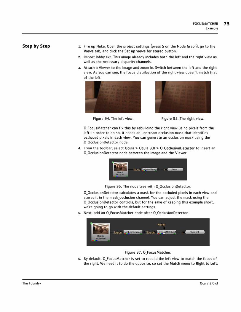
FOCUSMATCHER 73Example
Step by Step 1. Fire up Nuke. Open the project settings (press S on the Node Graph), go to the Views tab, and click the Set up views for stereo button.
2. Import lobby.exr. This image already includes both the left and the right view as well as the necessary disparity channels.
3. Attach a Viewer to the image and zoom in. Switch between the left and the right view. As you can see, the focus distribution of the right view doesn’t match that
of the left.
O_FocusMatcher can fix this by rebuilding the right view using pixels from the left. In order to do so, it needs an upstream occlusion mask that identifies occluded pixels in each view. You can generate an occlusion mask using the O_OcclusionDetector node.
4. From the toolbar, select Ocula > Ocula 3.0 > O_OcclusionDetector to insert an O_OcclusionDetector node between the image and the Viewer.
Figure 96. The node tree with O_OcclusionDetector.
O_OcclusionDetector calculates a mask for the occluded pixels in each view and stores it in the mask_occlusion channel. You can adjust the mask using the O_OcclusionDetector controls, but for the sake of keeping this example short, we’re going to go with the default settings.
5. Next, add an O_FocusMatcher node after O_OcclusionDetector.
Figure 97. O_FocusMatcher.
6. By default, O_FocusMatcher is set to rebuild the left view to match the focus of the right. We need it to do the opposite, so set the Match menu to Right to Left.
Figure 94. The left view. Figure 95. The right view.
Ocula 3.0v3The Foundry
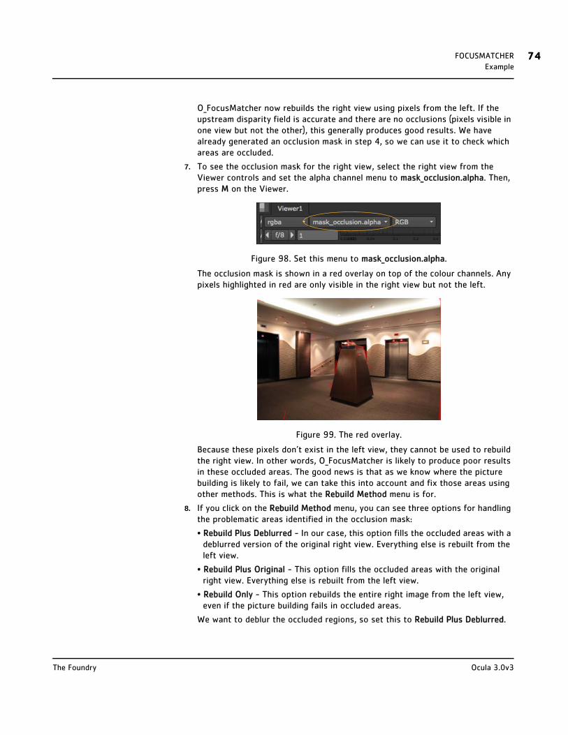
FOCUSMATCHER 74Example
O_FocusMatcher now rebuilds the right view using pixels from the left. If the upstream disparity field is accurate and there are no occlusions (pixels visible in one view but not the other), this generally produces good results. We have already generated an occlusion mask in step 4, so we can use it to check which areas are occluded.
7. To see the occlusion mask for the right view, select the right view from the Viewer controls and set the alpha channel menu to mask_occlusion.alpha. Then, press M on the Viewer.
Figure 98. Set this menu to mask_occlusion.alpha.
The occlusion mask is shown in a red overlay on top of the colour channels. Any pixels highlighted in red are only visible in the right view but not the left.
Figure 99. The red overlay.
Because these pixels don’t exist in the left view, they cannot be used to rebuild the right view. In other words, O_FocusMatcher is likely to produce poor results in these occluded areas. The good news is that as we know where the picture building is likely to fail, we can take this into account and fix those areas using other methods. This is what the Rebuild Method menu is for.
8. If you click on the Rebuild Method menu, you can see three options for handling the problematic areas identified in the occlusion mask:
• Rebuild Plus Deblurred - In our case, this option fills the occluded areas with a deblurred version of the original right view. Everything else is rebuilt from the left view.
• Rebuild Plus Original - This option fills the occluded areas with the original right view. Everything else is rebuilt from the left view.
• Rebuild Only - This option rebuilds the entire right image from the left view, even if the picture building fails in occluded areas.
We want to deblur the occluded regions, so set this to Rebuild Plus Deblurred.
Ocula 3.0v3The Foundry
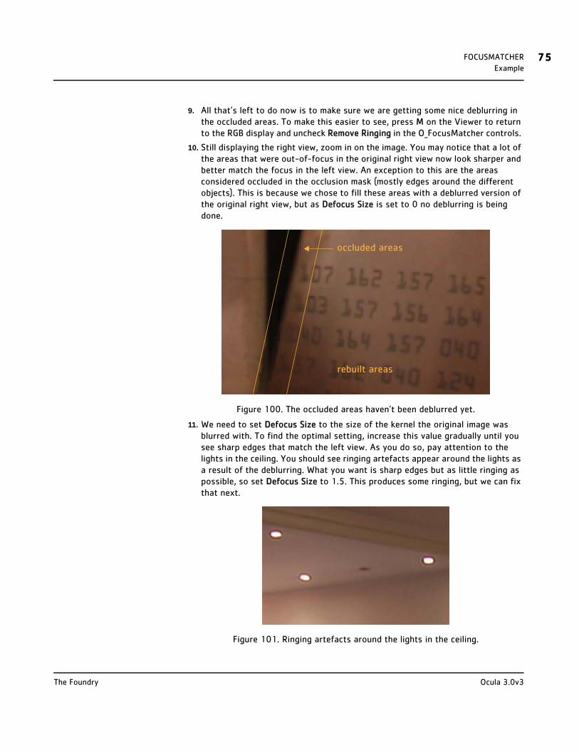
FOCUSMATCHER 75Example
9. All that’s left to do now is to make sure we are getting some nice deblurring in the occluded areas. To make this easier to see, press M on the Viewer to return to the RGB display and uncheck Remove Ringing in the O_FocusMatcher controls.
10. Still displaying the right view, zoom in on the image. You may notice that a lot of the areas that were out-of-focus in the original right view now look sharper and better match the focus in the left view. An exception to this are the areas considered occluded in the occlusion mask (mostly edges around the different objects). This is because we chose to fill these areas with a deblurred version of the original right view, but as Defocus Size is set to 0 no deblurring is being done.
Figure 100. The occluded areas haven’t been deblurred yet.
11. We need to set Defocus Size to the size of the kernel the original image was blurred with. To find the optimal setting, increase this value gradually until you see sharp edges that match the left view. As you do so, pay attention to the lights in the ceiling. You should see ringing artefacts appear around the lights as a result of the deblurring. What you want is sharp edges but as little ringing as possible, so set Defocus Size to 1.5. This produces some ringing, but we can fix that next.
Figure 101. Ringing artefacts around the lights in the ceiling.
rebuilt areas
occluded areas
Ocula 3.0v3The Foundry
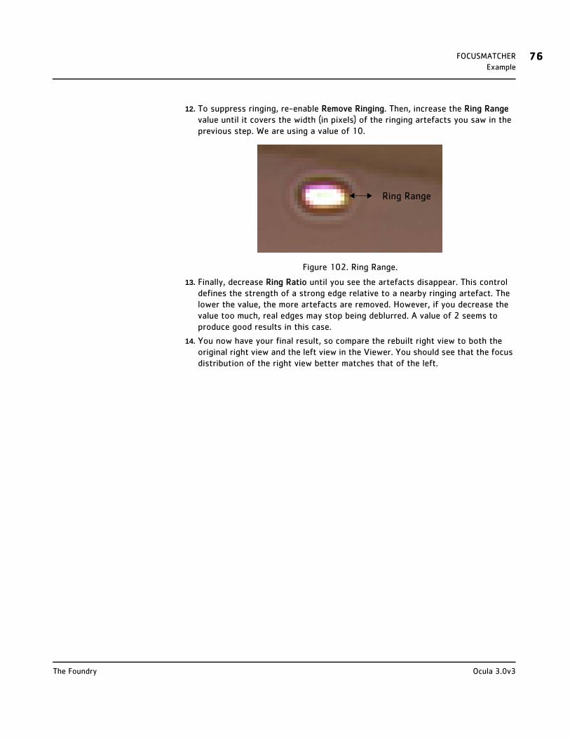
FOCUSMATCHER 76Example
12. To suppress ringing, re-enable Remove Ringing. Then, increase the Ring Range value until it covers the width (in pixels) of the ringing artefacts you saw in the previous step. We are using a value of 10.
Figure 102. Ring Range.
13. Finally, decrease Ring Ratio until you see the artefacts disappear. This control defines the strength of a strong edge relative to a nearby ringing artefact. The lower the value, the more artefacts are removed. However, if you decrease the value too much, real edges may stop being deblurred. A value of 2 seems to produce good results in this case.
14. You now have your final result, so compare the rebuilt right view to both the original right view and the left view in the Viewer. You should see that the focus distribution of the right view better matches that of the left.
Ring Range
Ocula 3.0v3The Foundry

VERTICALALIGNER
Description If the cameras used to shoot stereoscopic images are poorly positioned or converge (point inwards), some features in the resulting two views may be vertically misaligned. In the case of converging cameras, the misalignment may be due to keystoning. Unlike converging cameras, parallel cameras do not produce keystoning. This is illustrated in Figure 103 and Figure 104.
Converging cameras cause keystoning because the angle created affects the perspective in the two views. As a result, corresponding points in the two views are vertically misaligned. This is illustrated in Figure 105 and Figure 106.
Whether the vertical misalignment was caused by poorly positioned or converging cameras, it can lead into an unpleasant 3D stereo viewing experience. When a vertically misaligned stereo image is viewed with 3D glasses, the viewer’s mind attempts to line up the corresponding points in the images, often causing eye strain and headaches. To avoid this, stereo images should only contain horizontal disparity, not vertical.
The O_VerticalAligner plug-in lets you warp views vertically so that their
Figure 103. Parallel cameras do not cause keystoning.
Figure 104. Converging cameras do cause keystoning.
Figure 105. The left image. Figure 106. The right image.
L R
subject
RL
subject
L
L1L2
L3L4
R
R1R2
R3R4

VERTICALALIGNER 78Description
corresponding features align horizontally. The Vertical Skew and Local Alignment options allow you to warp the views while keeping the horizontal position of each pixel the same so that there is no change in convergence. An example is shown in Figure 107 and Figure 108.
You can choose between two warp modes: Global Alignment and Local Alignment. In the Global Alignment mode, O_VerticalAligner performs a global transform to align the views. In the Local Alignment mode, it rebuilds the image per-pixel to account for any local distortions in the mirror or lens and changes in alignment with depth.
In the Global Alignment mode, you can choose between several alignment methods. All methods concatenate. This means that if you add a row of O_VerticalAligner nodes to a tree, their functions are combined. Because the image is only resampled once, there is no loss of image quality and processing time is decreased.
If you have a pretracked Nuke stereo camera that describes the camera setup used to shoot the Source images, you can also use O_VerticalAligner in the Global Alignment mode to analyse the sequence and output a vertically aligned camera pair. This works with all global methods except Vertical Skew (which can't be represented by a camera transform). For more information, see Analysing and Using Output Data on page 80.
In the Local Alignment mode, O_VerticalAligner always requires a disparity field upstream. You can create one using the Solver and DisparityGenerator nodes.
Note If disparity channels are fed into this plug-in, they are not passed through to the output. This is because after warping the input images the original disparity field is no longer valid. If you need disparity channels further down the tree, add an O_DisparityGenerator node after O_VerticalAligner. When using Local Alignment, you also need to use O_Solver before O_DisparityGenerator to recalculate the solve.
Figure 107. Before O_VerticalAligner. Figure 108. After O_VerticalAligner.
Ocula 3.0v3The Foundry

VERTICALALIGNER 79Inputs
Inputs O_VerticalAligner has two inputs:
• Source - A stereo pair of images.
In the Global Alignment mode, if you’re not using the Solver input, the images should be followed by an O_Solver node.
In the Local Alignment mode, you need an O_Solver node and a disparity field in this input. You can create a disparity field using O_DisparityGenerator.
• Solver - If you’re using the Global Alignment mode and the Source sequence doesn’t contain features that O_Solver is able to match well, you can use O_Solver on another sequence shot with the same camera setup. If you do so, connect O_Solver to this input.
To see a table listing the nodes or channels each Ocula node requires in its inputs, turn to Appendix B: Node Dependencies on page 155.
Quick Start To align a stereo pair of images vertically, you can either:
• apply a global image transform to align the feature matches generated by an upstream O_Solver node. This allows you to have multiple O_VerticalAligner nodes that concatenate with a single filter hit. If you have a pretracked Nuke stereo camera that describes the camera setup used to shoot the Source images, you can also analyse the sequence and output a vertically aligned camera pair. See Global Alignment.
• rebuild the view(s) to remove vertical disparity calculated by an upstream O_DisparityGenerator. This allows you to account for any local distortions in the mirror or lens and changes in alignment with depth. See Global Alignment.
Global Alignment 1. Select Ocula > Ocula 3.0 > O_Solver to insert an O_Solver node after your stereo clip. For more information on how to use O_Solver, see Solver on page 18.
2. Select Ocula > Ocula 3.0 > O_VerticalAligner to insert an O_VerticalAligner node after either O_Solver. In most cases, the O_Solver node should be connected to the Source input of O_VerticalAligner (Figure 109). However, if you want to adjust the vertical alignment of one clip by using the O_Solver node of another, connect the O_Solver node to the Solver input of O_VerticalAligner (Figure 110).
Ocula 3.0v3The Foundry
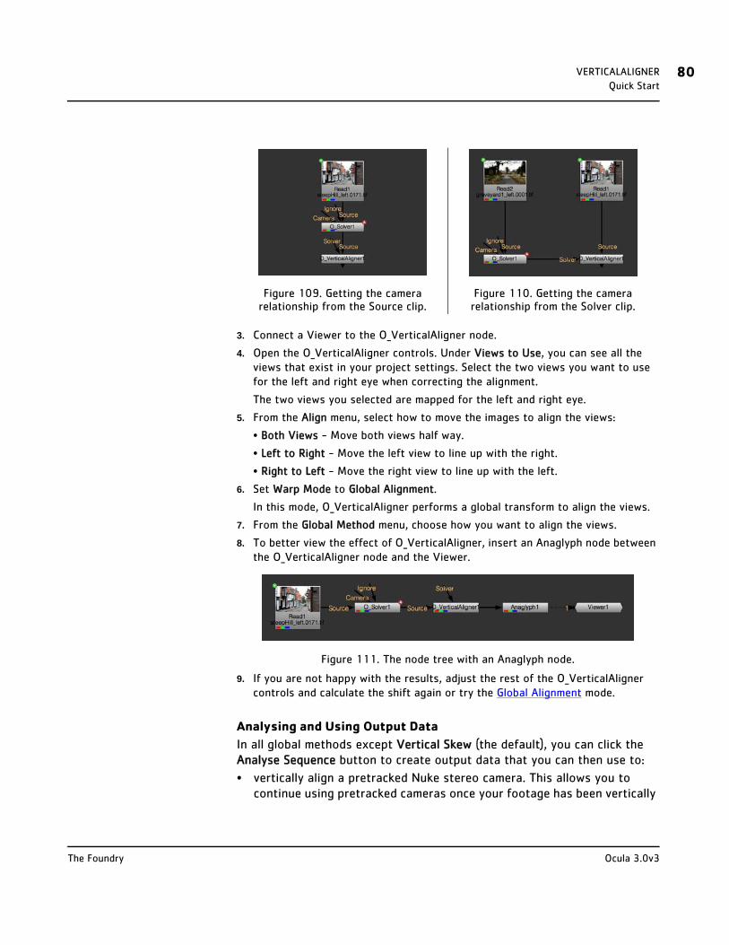
VERTICALALIGNER 80Quick Start
3. Connect a Viewer to the O_VerticalAligner node.
4. Open the O_VerticalAligner controls. Under Views to Use, you can see all the views that exist in your project settings. Select the two views you want to use for the left and right eye when correcting the alignment.
The two views you selected are mapped for the left and right eye.
5. From the Align menu, select how to move the images to align the views:
• Both Views - Move both views half way.
• Left to Right - Move the left view to line up with the right.
• Right to Left - Move the right view to line up with the left.
6. Set Warp Mode to Global Alignment.
In this mode, O_VerticalAligner performs a global transform to align the views.
7. From the Global Method menu, choose how you want to align the views.
8. To better view the effect of O_VerticalAligner, insert an Anaglyph node between the O_VerticalAligner node and the Viewer.
Figure 111. The node tree with an Anaglyph node.
9. If you are not happy with the results, adjust the rest of the O_VerticalAligner controls and calculate the shift again or try the Global Alignment mode.
Analysing and Using Output Data
In all global methods except Vertical Skew (the default), you can click the Analyse Sequence button to create output data that you can then use to:
• vertically align a pretracked Nuke stereo camera. This allows you to continue using pretracked cameras once your footage has been vertically
Figure 109. Getting the camera relationship from the Source clip.
Figure 110. Getting the camera relationship from the Solver clip.
Ocula 3.0v3The Foundry
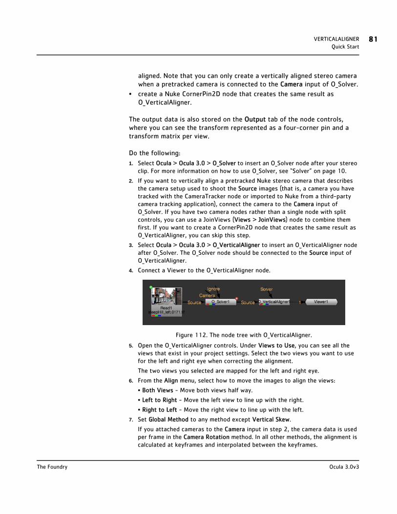
VERTICALALIGNER 81Quick Start
aligned. Note that you can only create a vertically aligned stereo camera when a pretracked camera is connected to the Camera input of O_Solver.
• create a Nuke CornerPin2D node that creates the same result as O_VerticalAligner.
The output data is also stored on the Output tab of the node controls, where you can see the transform represented as a four-corner pin and a transform matrix per view.
Do the following:
1. Select Ocula > Ocula 3.0 > O_Solver to insert an O_Solver node after your stereo clip. For more information on how to use O_Solver, see “Solver” on page 10.
2. If you want to vertically align a pretracked Nuke stereo camera that describes the camera setup used to shoot the Source images (that is, a camera you have tracked with the CameraTracker node or imported to Nuke from a third-party camera tracking application), connect the camera to the Camera input of O_Solver. If you have two camera nodes rather than a single node with split controls, you can use a JoinViews (Views > JoinViews) node to combine them first. If you want to create a CornerPin2D node that creates the same result as O_VerticalAligner, you can skip this step.
3. Select Ocula > Ocula 3.0 > O_VerticalAligner to insert an O_VerticalAligner node after O_Solver. The O_Solver node should be connected to the Source input of O_VerticalAligner.
4. Connect a Viewer to the O_VerticalAligner node.
Figure 112. The node tree with O_VerticalAligner.
5. Open the O_VerticalAligner controls. Under Views to Use, you can see all the views that exist in your project settings. Select the two views you want to use for the left and right eye when correcting the alignment.
The two views you selected are mapped for the left and right eye.
6. From the Align menu, select how to move the images to align the views:
• Both Views - Move both views half way.
• Left to Right - Move the left view to line up with the right.
• Right to Left - Move the right view to line up with the left.
7. Set Global Method to any method except Vertical Skew.
If you attached cameras to the Camera input in step 2, the camera data is used per frame in the Camera Rotation method. In all other methods, the alignment is calculated at keyframes and interpolated between the keyframes.
Ocula 3.0v3The Foundry
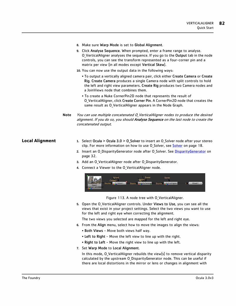
VERTICALALIGNER 82Quick Start
8. Make sure Warp Mode is set to Global Alignment.
9. Click Analyse Sequence. When prompted, enter a frame range to analyse. O_VerticalAligner analyses the sequence. If you go to the Output tab in the node controls, you can see the transform represented as a four-corner pin and a matrix per view (in all modes except Vertical Skew).
10. You can now use the output data in the following ways:
• To output a vertically aligned camera pair, click either Create Camera or Create Rig. Create Camera produces a single Camera node with split controls to hold the left and right view parameters. Create Rig produces two Camera nodes and a JoinViews node that combines them.
• To create a Nuke CornerPin2D node that represents the result of O_VerticalAligner, click Create Corner Pin. A CornerPin2D node that creates the same result as O_VerticalAligner appears in the Node Graph.
Note You can use multiple concatenated O_VerticalAligner nodes to produce the desired alignment. If you do so, you should Analyse Sequence on the last node to create the concatenated output.
Local Alignment 1. Select Ocula > Ocula 3.0 > O_Solver to insert an O_Solver node after your stereo clip. For more information on how to use O_Solver, see Solver on page 18.
2. Insert an O_DisparityGenerator node after O_Solver. See DisparityGenerator on page 32.
3. Add an O_VerticalAligner node after O_DisparityGenerator.
4. Connect a Viewer to the O_VerticalAligner node.
Figure 113. A node tree with O_VerticalAligner.
5. Open the O_VerticalAligner controls. Under Views to Use, you can see all the views that exist in your project settings. Select the two views you want to use for the left and right eye when correcting the alignment.
The two views you selected are mapped for the left and right eye.
6. From the Align menu, select how to move the images to align the views:
• Both Views - Move both views half way.
• Left to Right - Move the left view to line up with the right.
• Right to Left - Move the right view to line up with the left.
7. Set Warp Mode to Local Alignment.
In this mode, O_VerticalAligner rebuilds the view(s) to remove vertical disparity calculated by the upstream O_DisparityGenerator node. This can be useful if there are local distortions in the mirror or lens or changes in alignment with
Ocula 3.0v3The Foundry
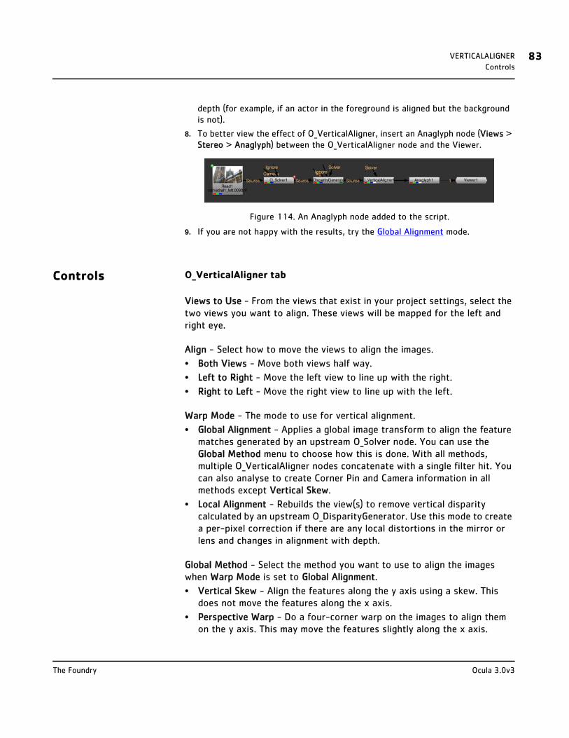
VERTICALALIGNER 83Controls
depth (for example, if an actor in the foreground is aligned but the background is not).
8. To better view the effect of O_VerticalAligner, insert an Anaglyph node (Views > Stereo > Anaglyph) between the O_VerticalAligner node and the Viewer.
Figure 114. An Anaglyph node added to the script.
9. If you are not happy with the results, try the Global Alignment mode.
Controls O_VerticalAligner tab
Views to Use - From the views that exist in your project settings, select the two views you want to align. These views will be mapped for the left and right eye.
Align - Select how to move the views to align the images.
• Both Views - Move both views half way.
• Left to Right - Move the left view to line up with the right.
• Right to Left - Move the right view to line up with the left.
Warp Mode - The mode to use for vertical alignment.
• Global Alignment - Applies a global image transform to align the feature matches generated by an upstream O_Solver node. You can use the Global Method menu to choose how this is done. With all methods, multiple O_VerticalAligner nodes concatenate with a single filter hit. You can also analyse to create Corner Pin and Camera information in all methods except Vertical Skew.
• Local Alignment - Rebuilds the view(s) to remove vertical disparity calculated by an upstream O_DisparityGenerator. Use this mode to create a per-pixel correction if there are any local distortions in the mirror or lens and changes in alignment with depth.
Global Method - Select the method you want to use to align the images when Warp Mode is set to Global Alignment.
• Vertical Skew - Align the features along the y axis using a skew. This does not move the features along the x axis.
• Perspective Warp - Do a four-corner warp on the images to align them on the y axis. This may move the features slightly along the x axis.
Ocula 3.0v3The Foundry
VERTICALALIGNER 84Controls
• Rotation - Align the features vertically by rotating the entire image around a point. The centre of the rotation is determined by the algorithm.
• Scale - Align the features vertically by scaling the image.
• Simple Shift - Align the features vertically by moving the entire image up or down.
• Scale Rotate - Align the features vertically by simultaneously scaling and rotating the entire image around a point. The centre of the rotation is determined by the algorithm.
• Camera Rotation - Align the features by first performing a 3D rotation of both cameras so that they have exactly the same orientation and a parallel viewing axis, and then reconverging the views to provide the original convergence. This method requires the camera geometry provided by an upstream O_Solver node. For best results, use the O_Solver Camera input to provide the information for the shooting cameras. If a Camera input is connected, the camera data is used per frame (rather than only taken from keyframes).
Filter - Select the filtering algorithm to use when remapping pixels from their original positions to new positions. This allows you to avoid problems with image quality, particularly in high contrast areas of the frame (where highly aliased, or jaggy, edges may appear if pixels are not filtered and retain their original values). This control is only available if you have set Warp Mode to Global Alignment.
• Impulse - Remapped pixels carry their original values.
• Cubic - Remapped pixels receive some smoothing.
• Keys - Remapped pixels receive some smoothing, plus minor sharpening.
• Simon - Remapped pixels receive some smoothing, plus medium sharpening.
• Rifman - Remapped pixels receive some smoothing, plus significant sharpening.
• Mitchell - Remapped pixels receive some smoothing, plus blurring to hide pixelation.
• Parzen - Remapped pixels receive the greatest smoothing of all filters.
• Notch - Remapped pixels receive flat smoothing (which tends to hide Moiré patterns).
Analyse Sequence - Analyse the sequence to create a corner pin or aligned camera output. Use Analyse Sequence to create the output data in all global methods except Vertical Skew (the default). Then, use Create Corner Pin, Create Camera, or Create Rig.
Create Corner Pin - Click this to create a corner pin representing the result
Ocula 3.0v3The Foundry
VERTICALALIGNER 85Example
of O_VerticalAligner once you have clicked Analyse Sequence. You can use multiple O_VerticalAligner nodes to produce the desired alignment. Then, analyse on the final node to create a single corner pin to represent the concatenated transform. This works in all global methods except Vertical Skew (the default).
Create Camera - If you have a pretracked Nuke stereo camera connected to the Camera input of the O_Solver up the tree and you have clicked Analyse Sequence, you can click this to create a vertically aligned camera from the analysis. This gives you a single Camera node with split controls to hold the left and right view parameters. This works in all global methods except Vertical Skew (the default).
Create Rig - If you have a pretracked Nuke stereo camera connected to the Camera input of the O_Solver up the tree and you have clicked Analyse Sequence, you can click this to create a vertically aligned camera rig from the analysis. This gives you two Camera nodes and a JoinViews node that combines them. This works in all global methods except Vertical Skew (the default).
Output tab
Four Corner Pin - This represents the 2D corner pin that can be applied to the input image to create the same result as O_VerticalAligner (in all global methods except Vertical Skew). This allows you to do the analysis in Nuke, but take the matrix to a third-party application, such as Baselight, and align the image or camera there.
Transform Matrix - This provides the concatenated 2D transform for the vertical alignment. The matrix is filled when you click Analyse Sequence on the O_VerticalAligner tab. There is one matrix for each view in the source.
Example In this example, we correct the vertical alignment of a stereo image using the Global Alignment mode. The image used here can be downloaded from our web site. For more information, please see Example Images on page 6.
Step by Step 1. Fire up Nuke. Open the project settings (press S on the Node Graph), go to the Views tab, and click the Set up views for stereo button.
2. Import the steep_hill.exr image and connect it to a Viewer. The image includes both the left and the right view.
Ocula 3.0v3The Foundry
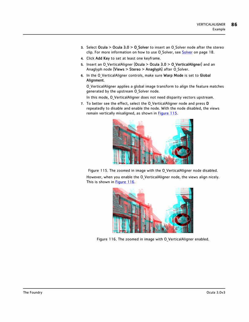
VERTICALALIGNER 86Example
3. Select Ocula > Ocula 3.0 > O_Solver to insert an O_Solver node after the stereo clip. For more information on how to use O_Solver, see Solver on page 18.
4. Click Add Key to set at least one keyframe.
5. Insert an O_VerticalAligner (Ocula > Ocula 3.0 > O_VerticalAligner) and an Anaglyph node (Views > Stereo > Anaglyph) after O_Solver.
6. In the O_VerticalAligner controls, make sure Warp Mode is set to Global Alignment.
O_VerticalAligner applies a global image transform to align the feature matches generated by the upstream O_Solver node.
In this mode, O_VerticalAligner does not need disparity vectors upstream.
7. To better see the effect, select the O_VerticalAligner node and press D repeatedly to disable and enable the node. With the node disabled, the views remain vertically misaligned, as shown in Figure 115.
Figure 115. The zoomed in image with the O_VerticalAligner node disabled.
However, when you enable the O_VerticalAligner node, the views align nicely. This is shown in Figure 116.
Figure 116. The zoomed in image with O_VerticalAligner enabled.
Ocula 3.0v3The Foundry

NEWVIEW
Description Using the O_NewView plug-in, you can create a single view from a stereo pair of images. You can create this new view at any position between the original views. The new view replaces both of the existing views.
You can choose to construct the new view using one or both of the original views. Using just one view can be useful if you want to manipulate it with a gizmo, a plug-in, or a graphics editor, for example, and copy your changes into the other view. You can make your changes to one view, and use the O_NewView plug-in to generate the other view with these changes reproduced in the correct position.
If there are no occlusions (features visible in one view but not the other), O_NewView generally produces good results. When there are occlusions, the results may require further editing but can often save you time over not using the plug-in at all.
To generate the new view, the O_NewView plug-in needs disparity vectors that relate the two views. You can use the O_Solver and O_DisparityGenerator plug-ins to calculate these vectors. See Solver on page 18 and DisparityGenerator on page 32 for how to do this.
If you use O_NewView to reproduce changes made to one view in the other view, you may want to create the disparity vectors using either the modified view and its corresponding view, or the original views with no changes applied. Which you choose depends on which you think will produce better disparity vectors. The former method may be preferable, if you are correcting an unwanted colour shift between views, for example. The latter method usually works best if your changes in one view produce an occlusion in the images, for example, when using a texture replacement plug-in or painting something on one view in another application.
Note that to reproduce changes you’ve made using Nuke’s Roto node, RotoPaint node, or any node or gizmo that has controls for x and y coordinates, it is easier to use the O_Correlate plug-in described on page 110.
Tip O_NewView is often used as a troubleshooting tool, to judge the quality of a particular disparity field.

NEWVIEW 88Inputs
Inputs O_NewView has two inputs:
• Source - A stereo pair of images. If disparity channels aren’t embedded in the images, you should add an O_Solver and an O_DisparityGenerator node after the image sequence.
• Fg - An optional mask that delineates foreground regions from background. The mask ensures that disparities are constrained to remain within each delineated region. Note that masks should exist in both views, and O_NewView expects alpha values of either 0 (for background) or 1 (for foreground).
Note that the Fg input only has an effect when Inputs is set to Both and Interpolate Position is greater than 0 and less than 1.
To see a table listing the nodes or channels each Ocula node requires in its inputs, turn to Appendix B: Node Dependencies on page 155.
Quick Start To create a new view:
1. If there are disparity vectors in the data stream from an earlier O_DisparityGenerator node, or if disparity vectors exist in the image sequence itself, these are used when generating the new view. If disparity vectors don’t yet exist in the script, however, you can use a combination of the O_Solver and O_DisparityGenerator plug-ins to calculate the disparity vectors. Select Ocula > Ocula 3.0 > O_Solver and Ocula > Ocula 3.0 > O_DisparityGenerator to insert these in an appropriate place in your script.
2. Select Ocula > Ocula 3.0 > O_NewView to insert an O_NewView node after either the O_DisparityGenerator node or the stereo image sequence.
3. Using the Views to Use controls, select the views you want to map for the left and right eye.
4. From the Inputs pulldown menu, select which input(s) you want to use to create the new view:
• Left - Only use the image mapped for the left eye to create the new view.
• Right - Only use the image mapped for the right eye to create the new view.
• Both - Use both images to create the new view.
5. Adjust the Interpolate Position slider to define where to build the new view. The values are expressed as a fraction of the distance between the two views.
6. Attach a Viewer to the O_NewView node.
Ocula 3.0v3The Foundry

NEWVIEW 89Controls
Figure 117. A node tree with O_NewView. The O_Solver and O_DisparityGenerator nodes are not needed in this tree if the necessary disparity channels are included in
the Read node.
7. If you are not happy with the results, try adjusting the rest of the O_NewView controls. They are described below.
Controls Views to Use - From the views that exist in your project settings, select the two views you want to use to create the new view. These views will be mapped for the left and right eye.
Inputs - Select which inputs to use to generate the new view.
• Left - Only use the input mapped for the left eye to create the new view.
• Right - Only use the input mapped for the right eye to create the new view.
• Both - Use both inputs to create the new view.
Interpolate Position - Select the position between the existing views where you want to generate the new view. The position is expressed as a fraction of the distance between the views.
Filtering - Set the quality of filtering.
• Extreme - Uses a sinc interpolation filter to give a sharper picture but takes a lot longer to render.
• Normal - Uses bilinear interpolation which gives good results and is a lot quicker than extreme.
Warp Mode - Select a method to use to generate the new view.
• Simple - This is the quickest option, but may produce less than optimal results around image edges and objects that are visible in one view but not the other.
• Normal - This is the standard option, with more optimal treatment of image edges and occlusions.
• Occlusions - This is an advanced option that may improve the results.
• Sharp Occlusions - This option is similar to Occlusions, but produces fewer artifacts where the disparity fields are generated from 3D CG sources.
Ocula 3.0v3The Foundry

NEWVIEW 90Example
Foreground Component - Select the channel to use to delineate foreground regions from background. The mask ensures that disparities are constrained to remain within each delineated region.
• None - Use the entire image area.
• Source Alpha - Use the alpha channel of the Source clip.
• Source Inverted Alpha - Use the inverted alpha channel of the Source clip.
• Mask Luminance - Use the luminance of the Fg input.
• Mask Inverted Luminance - Use the inverted luminance of the Fg input.
• Mask Alpha - Use the alpha channel of the Fg input.
• Mask Inverted Alpha - Use the inverted alpha channel of the Fg input.
Example In this example, we have a stereo image of a cathedral. In the left view, one of the cathedral windows has been removed using F_BlockTexture - a texture replacement tool included in The Foundry’s Furnace plug-ins. Our aim is to reproduce this change in the right view using the O_NewView plug-in. We construct a new right view from the left view, with the changes in the correct position.
The stereo image used in the example can be downloaded from our web site. For more information, please see Example Images on page 6.
The necessary disparity channels have been embedded in the download image, so you don’t need to use the O_Solver and O_DisparityGenerator plug-ins in this example. However, you should note that the disparity channels were calculated using the original left and right views (with the window still in place in both views). This is because removing the window from one view but not the other produces an occlusion, and the O_NewView plug-in works better when there are no occlusions.
Step by Step 1. Start Nuke and open the project settings (press S on the Node Graph). Go to the Views tab and click the Set up views for stereo button.
2. Import cathedral1.exr and attach a Viewer to the image. Switch between the left and the right view. Notice how in the left view, the cathedral has one window less than in the right view. This is highlighted in Figure 118 and Figure 119.
Ocula 3.0v3The Foundry

NEWVIEW 91Example
We want to reproduce this change made to the left view in the right view using the O_NewView plug-in.
3. Select Ocula > Ocula 3.0 > O_NewView to insert an O_NewView node between the stereo image and the Viewer.
4. In the O_NewView controls, select Left from the Inputs menu to generate the new view from the left view. Enter 1 as the Interpolate Position to create the new view in the same position as the original right view.
As you can see from Figure 120, the window disappears from the right view, but the O_NewView plug-in creates some unwanted changes around the edges of the new view.
Figure 120. The new view generated with O_NewView.
To prevent this, we can take the area around the window from the new view, and composite that over the original right view.
5. Select the O_NewView node and Draw > Roto from the Toolbar (or press O on the Node Graph).
This inserts a Roto node after O_NewView.
6. In the Roto controls, change the output to alpha, and premultiply to rgba.
The Viewer goes black. Attach it to the Read node (rather than the Roto node) and display the right view.
7. Using the Roto Bezier tool, draw a shape around the window that was removed from the left view. Figure 121 shows a quickly drawn example of what your shape might now look like.
Figure 118. The left view. Figure 119. The right view.
Ocula 3.0v3The Foundry

NEWVIEW 92Example
Figure 121. Drawing a Bezier around the window.
8. Attach the Viewer to the Roto node now, and zoom out if necessary. You should only see the area you defined with the Roto node. This is what we are going to composite over the original right view.
9. To extract the original right view from the original Read node, click on an empty space in the Node Graph and select Views > OneView from the Toolbar. Connect the OneView node into the Read node.
10. In the OneView controls, select right from the view menu. If you now view the output of OneView, you should see the original right view with the window still in place.
11. To composite the output from the Roto node on top of the original right view, click on an empty spot in the Node Graph and select Merge > Merge (or press M). Connect the A input of the resulting over node into the Roto and the B input into the OneView node. Attach a Viewer to the Merge node. Your node tree should now look like the one in Figure 122.
Figure 122. The node tree that creates the final right view.
12. View the output of the Merge node. This is your final right view. Notice that the covered window has been copied from the left view into the correct position in the right view, but the rest of the right view hasn’t changed.
Ocula 3.0v3The Foundry

NEWVIEW 93Example
Figure 123. The final right view.
Now, we only need to combine the new right view with the original left view from the Read node.
13. Click on an empty spot in the Node Graph and select Views > JoinViews. Connect the left input from the JoinViews node into the Read node, and the right input into the Merge node. Attach a Viewer to the JoinViews node. Your node tree should look like the one in Figure 124.
Figure 124. The final node tree.
14. Using the Viewer controls, switch between the left and the right views. The changes made to the left view have been copied into the right view, in the correct position. This is shown in Figure 125 and Figure 126.
Figure 125. The left view. Figure 126. The new right view.
Ocula 3.0v3The Foundry

NEWVIEW 94Example
Tip To better see what the new view looks like, close the Roto node controls or press O on the Viewer to toggle the overlay off.
Ocula 3.0v3The Foundry
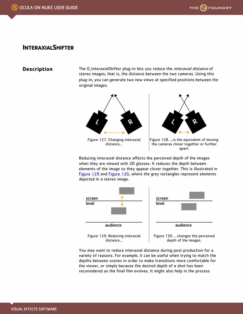
INTERAXIALSHIFTER
Description The O_InteraxialShifter plug-in lets you reduce the interaxial distance of stereo images; that is, the distance between the two cameras. Using this
plug-in, you can generate two new views at specified positions between the
original images.
Reducing interaxial distance affects the perceived depth of the images when they are viewed with 3D glasses. It reduces the depth between elements of the image so they appear closer together. This is illustrated in Figure 129 and Figure 130, where the grey rectangles represent elements depicted in a stereo image.
You may want to reduce interaxial distance during post production for a variety of reasons. For example, it can be useful when trying to match the depths between scenes in order to make transitions more comfortable for the viewer, or simply because the desired depth of a shot has been reconsidered as the final film evolves. It might also help in the process
Figure 127. Changing interaxial distance...
Figure 128. ...is the equivalent of moving the cameras closer together or further
apart.
Figure 129. Reducing interaxial distance...
Figure 130. ...changes the perceived depth of the images.
RL RL
audience
screen level
audience
screen level

INTERAXIALSHIFTER 96Inputs
known as depth grading, where the depth of field is adjusted in order to make sure the stereo effect can be comfortably viewed on the screen size for which the finished film is intended. The apparent depth of the scene will depend upon a combination of the screen size and the distance from the screen to the viewer.
If there are no occlusions (features visible in one view but not the other), O_InteraxialShifter generally produces good results. When there are occlusions, the results may require further editing but can often save you time over not using the plug-in at all, or the cost of a reshoot.
To generate the new view, the O_InteraxialShifter plug-in needs upstream disparity vectors that relate the two views. You can use the O_Solver and O_DisparityGenerator plug-ins to calculate these vectors. See NewView on page 87 and DisparityGenerator on page 32 for how to do this.
Note This plug-in does not pass through any disparity channels fed into it. This is because after warping the input images the original disparity field is no longer valid. If you need disparity channels further down the tree, add another O_DisparityGenerator after O_InteraxialShifter.
Note Changing interaxial distance is different to changing convergence (the inward rotation of the cameras). You can change convergence using Nuke’s ReConverge node. This way, you can have any selected point in the image appear at screen depth when viewed with 3D glasses.
Inputs O_InteraxialShifter has two inputs:
• Source - A stereo pair of images. If disparity channels aren’t embedded in the images, you should add an O_Solver and an O_DisparityGenerator node after the image sequence.
• Fg - An optional mask that delineates foreground regions from background. The mask ensures that disparities are constrained to remain within each delineated region. Note that masks should exist in both views, and O_InteraxialShifter expects alpha values of either 0 (for background) or 1 (for foreground).
To see a table listing the nodes or channels each Ocula node requires in its inputs, turn to Appendix B: Node Dependencies on page 155.
Quick Start To reduce interaxial distance, do the following:
1. If there are disparity vectors in the data stream from an earlier O_DisparityGenerator node, or if disparity vectors exist in the image sequence
Ocula 3.0v3The Foundry
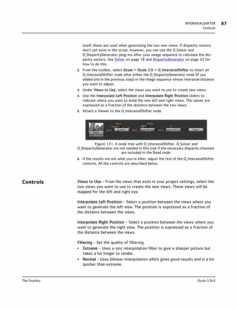
INTERAXIALSHIFTER 97Controls
itself, these are used when generating the two new views. If disparity vectors don’t yet exist in the script, however, you can use the O_Solver and O_DisparityGenerator plug-ins after your image sequence to calculate the dis-parity vectors. See Solver on page 18 and DisparityGenerator on page 32 for how to do this.
2. From the toolbar, select Ocula > Ocula 3.0 > O_InteraxialShifter to insert an O_InteraxialShifter node after either the O_DisparityGenerator node (if you added one in the previous step) or the image sequence whose interaxial distance you want to adjust.
3. Under Views to Use, select the views you want to use to create new views.
4. Use the Interpolate Left Position and Interpolate Right Position sliders to indicate where you want to build the new left and right views. The values are expressed as a fraction of the distance between the two views.
5. Attach a Viewer to the O_InteraxialShifter node.
Figure 131. A node tree with O_InteraxialShifter. O_Solver and O_DisparityGenerator are not needed in this tree if the necessary disparity channels
are included in the Read node.
6. If the results are not what you’re after, adjust the rest of the O_InteraxialShifter controls. All the controls are described below.
Controls Views to Use - From the views that exist in your project settings, select the two views you want to use to create the new views. These views will be mapped for the left and right eye.
Interpolate Left Position - Select a position between the views where you want to generate the left view. The position is expressed as a fraction of the distance between the views.
Interpolate Right Position - Select a position between the views where you want to generate the right view. The position is expressed as a fraction of the distance between the views.
Filtering - Set the quality of filtering.
• Extreme - Uses a sinc interpolation filter to give a sharper picture but takes a lot longer to render.
• Normal - Uses bilinear interpolation which gives good results and is a lot quicker than extreme.
Ocula 3.0v3The Foundry
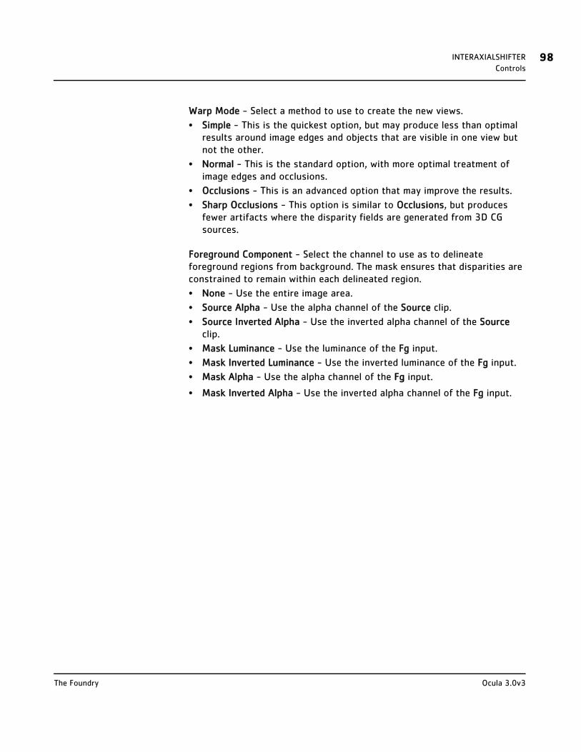
INTERAXIALSHIFTER 98Controls
Warp Mode - Select a method to use to create the new views.
• Simple - This is the quickest option, but may produce less than optimal results around image edges and objects that are visible in one view but not the other.
• Normal - This is the standard option, with more optimal treatment of image edges and occlusions.
• Occlusions - This is an advanced option that may improve the results.
• Sharp Occlusions - This option is similar to Occlusions, but produces fewer artifacts where the disparity fields are generated from 3D CG sources.
Foreground Component - Select the channel to use as to delineate foreground regions from background. The mask ensures that disparities are constrained to remain within each delineated region.
• None - Use the entire image area.
• Source Alpha - Use the alpha channel of the Source clip.
• Source Inverted Alpha - Use the inverted alpha channel of the Source clip.
• Mask Luminance - Use the luminance of the Fg input.
• Mask Inverted Luminance - Use the inverted luminance of the Fg input.
• Mask Alpha - Use the alpha channel of the Fg input.
• Mask Inverted Alpha - Use the inverted alpha channel of the Fg input.
Ocula 3.0v3The Foundry
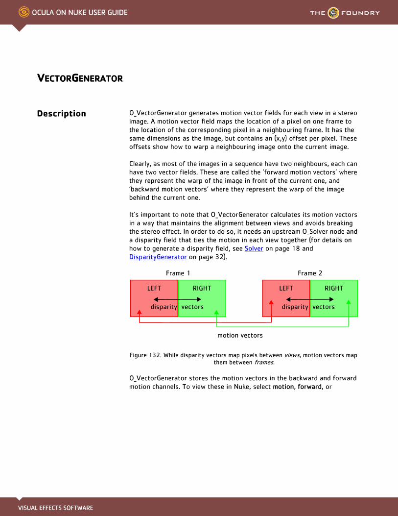
VECTORGENERATOR
Description O_VectorGenerator generates motion vector fields for each view in a stereo image. A motion vector field maps the location of a pixel on one frame to the location of the corresponding pixel in a neighbouring frame. It has the same dimensions as the image, but contains an (x,y) offset per pixel. These offsets show how to warp a neighbouring image onto the current image.
Clearly, as most of the images in a sequence have two neighbours, each can have two vector fields. These are called the ’forward motion vectors’ where they represent the warp of the image in front of the current one, and ’backward motion vectors’ where they represent the warp of the image behind the current one.
It’s important to note that O_VectorGenerator calculates its motion vectors in a way that maintains the alignment between views and avoids breaking the stereo effect. In order to do so, it needs an upstream O_Solver node and a disparity field that ties the motion in each view together (for details on how to generate a disparity field, see Solver on page 18 and DisparityGenerator on page 32).
Figure 132. While disparity vectors map pixels between views, motion vectors map them between frames.
O_VectorGenerator stores the motion vectors in the backward and forward motion channels. To view these in Nuke, select motion, forward, or
motion vectors
LEFT RIGHT
disparity vectors
LEFT RIGHT
disparity vectors
Frame 1 Frame 2
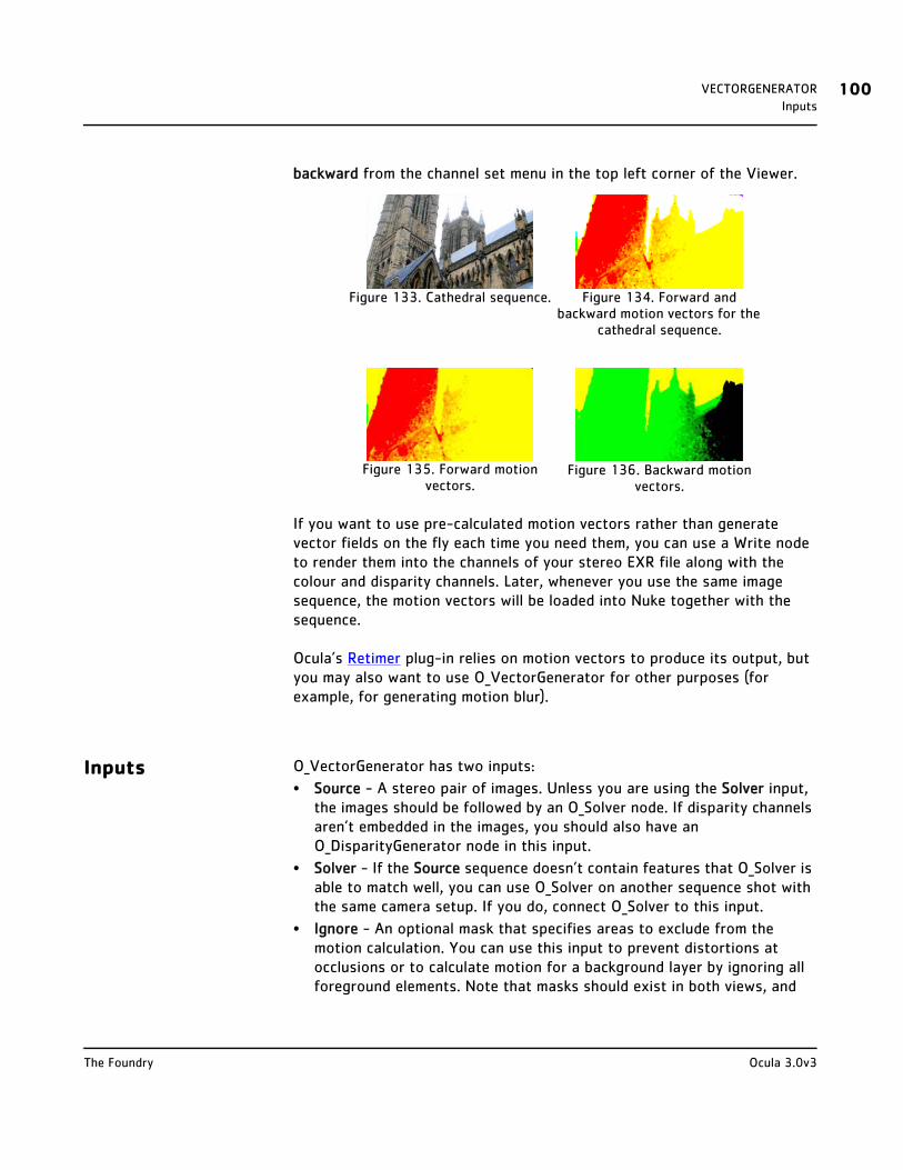
VECTORGENERATOR 100Inputs
backward from the channel set menu in the top left corner of the Viewer.
If you want to use pre-calculated motion vectors rather than generate vector fields on the fly each time you need them, you can use a Write node to render them into the channels of your stereo EXR file along with the colour and disparity channels. Later, whenever you use the same image sequence, the motion vectors will be loaded into Nuke together with the sequence.
Ocula’s Retimer plug-in relies on motion vectors to produce its output, but you may also want to use O_VectorGenerator for other purposes (for example, for generating motion blur).
Inputs O_VectorGenerator has two inputs:
• Source - A stereo pair of images. Unless you are using the Solver input, the images should be followed by an O_Solver node. If disparity channels aren’t embedded in the images, you should also have an O_DisparityGenerator node in this input.
• Solver - If the Source sequence doesn’t contain features that O_Solver is able to match well, you can use O_Solver on another sequence shot with the same camera setup. If you do, connect O_Solver to this input.
• Ignore - An optional mask that specifies areas to exclude from the motion calculation. You can use this input to prevent distortions at occlusions or to calculate motion for a background layer by ignoring all foreground elements. Note that masks should exist in both views, and
Figure 133. Cathedral sequence. Figure 134. Forward and backward motion vectors for the
cathedral sequence.
Figure 135. Forward motion vectors.
Figure 136. Backward motion vectors.
Ocula 3.0v3The Foundry
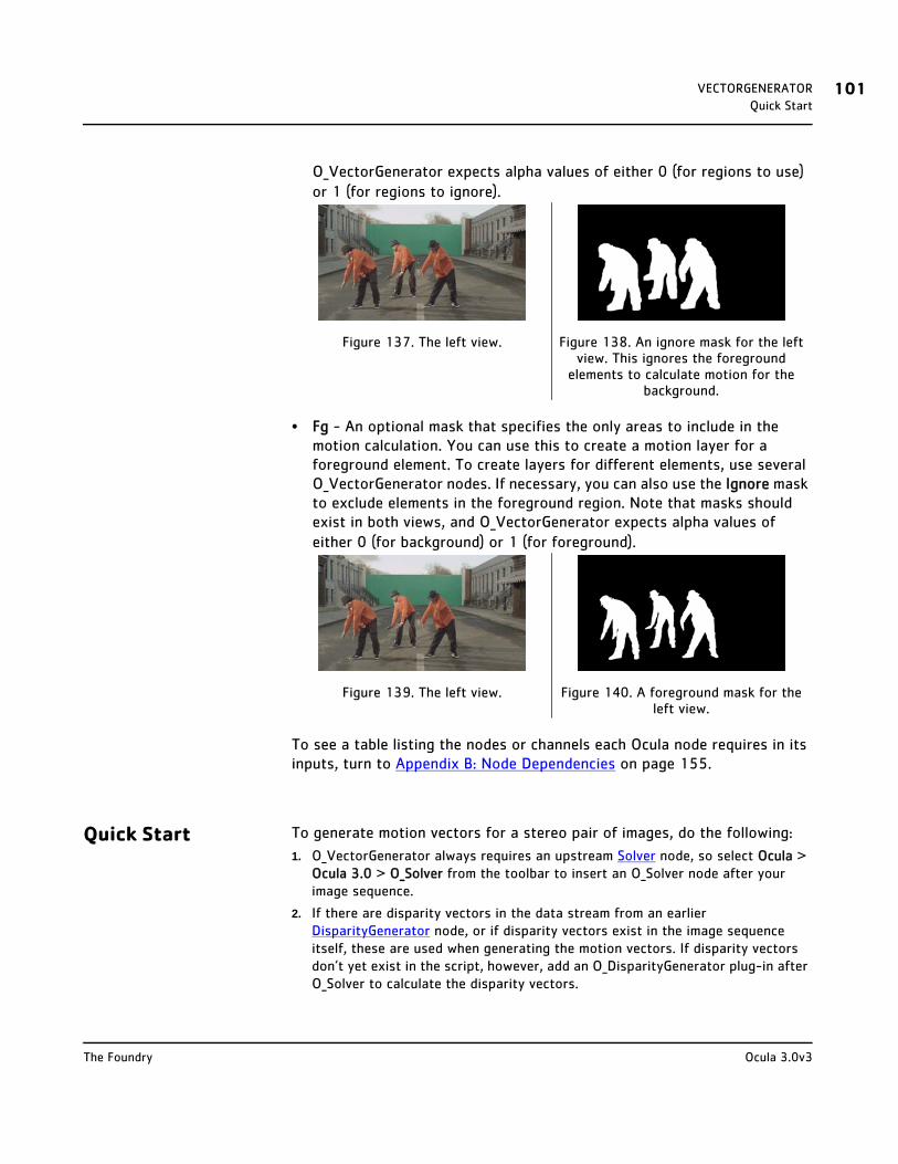
VECTORGENERATOR 101Quick Start
O_VectorGenerator expects alpha values of either 0 (for regions to use) or 1 (for regions to ignore).
• Fg - An optional mask that specifies the only areas to include in the motion calculation. You can use this to create a motion layer for a foreground element. To create layers for different elements, use several O_VectorGenerator nodes. If necessary, you can also use the Ignore mask to exclude elements in the foreground region. Note that masks should exist in both views, and O_VectorGenerator expects alpha values of either 0 (for background) or 1 (for foreground).
To see a table listing the nodes or channels each Ocula node requires in its inputs, turn to Appendix B: Node Dependencies on page 155.
Quick Start To generate motion vectors for a stereo pair of images, do the following:
1. O_VectorGenerator always requires an upstream Solver node, so select Ocula > Ocula 3.0 > O_Solver from the toolbar to insert an O_Solver node after your image sequence.
2. If there are disparity vectors in the data stream from an earlier DisparityGenerator node, or if disparity vectors exist in the image sequence itself, these are used when generating the motion vectors. If disparity vectors don’t yet exist in the script, however, add an O_DisparityGenerator plug-in after O_Solver to calculate the disparity vectors.
Figure 137. The left view. Figure 138. An ignore mask for the left view. This ignores the foreground
elements to calculate motion for the background.
Figure 139. The left view. Figure 140. A foreground mask for the left view.
Ocula 3.0v3The Foundry
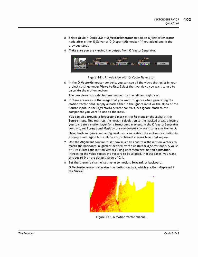
VECTORGENERATOR 102Quick Start
3. Select Ocula > Ocula 3.0 > O_VectorGenerator to add an O_VectorGenerator node after either O_Solver or O_DisparityGenerator (if you added one in the previous step).
4. Make sure you are viewing the output from O_VectorGenerator.
Figure 141. A node tree with O_VectorGenerator.
5. In the O_VectorGenerator controls, you can see all the views that exist in your project settings under Views to Use. Select the two views you want to use to calculate the motion vectors.
The two views you selected are mapped for the left and right eye.
6. If there are areas in the image that you want to ignore when generating the motion vector field, supply a mask either in the Ignore input or the alpha of the Source input. In the O_VectorGenerator controls, set Ignore Mask to the component you want to use as the mask.
You can also provide a foreground mask in the Fg input or the alpha of the Source input. This restricts the motion calculation to the masked areas, allowing you to create a motion layer for a foreground element. In the O_VectorGenerator controls, set Foreground Mask to the component you want to use as the mask.
Using both an Ignore and an Fg mask, you can restrict the motion calculation to a foreground region but exclude any problematic areas from that region.
7. Use the Alignment control to set how much to constrain the motion vectors to match the horizontal alignment defined by the upstream O_Solver node. A value of 0 calculates the motion vectors using unconstrained motion estimation. Increasing the value forces the vectors to be aligned. In most cases, you want this set to 0 or the default value of 0.1.
8. Set the Viewer’s channel set menu to motion, forward, or backward.
O_VectorGenerator calculates the motion vectors, which are then displayed in the Viewer.
Figure 142. A motion vector channel.
Ocula 3.0v3The Foundry
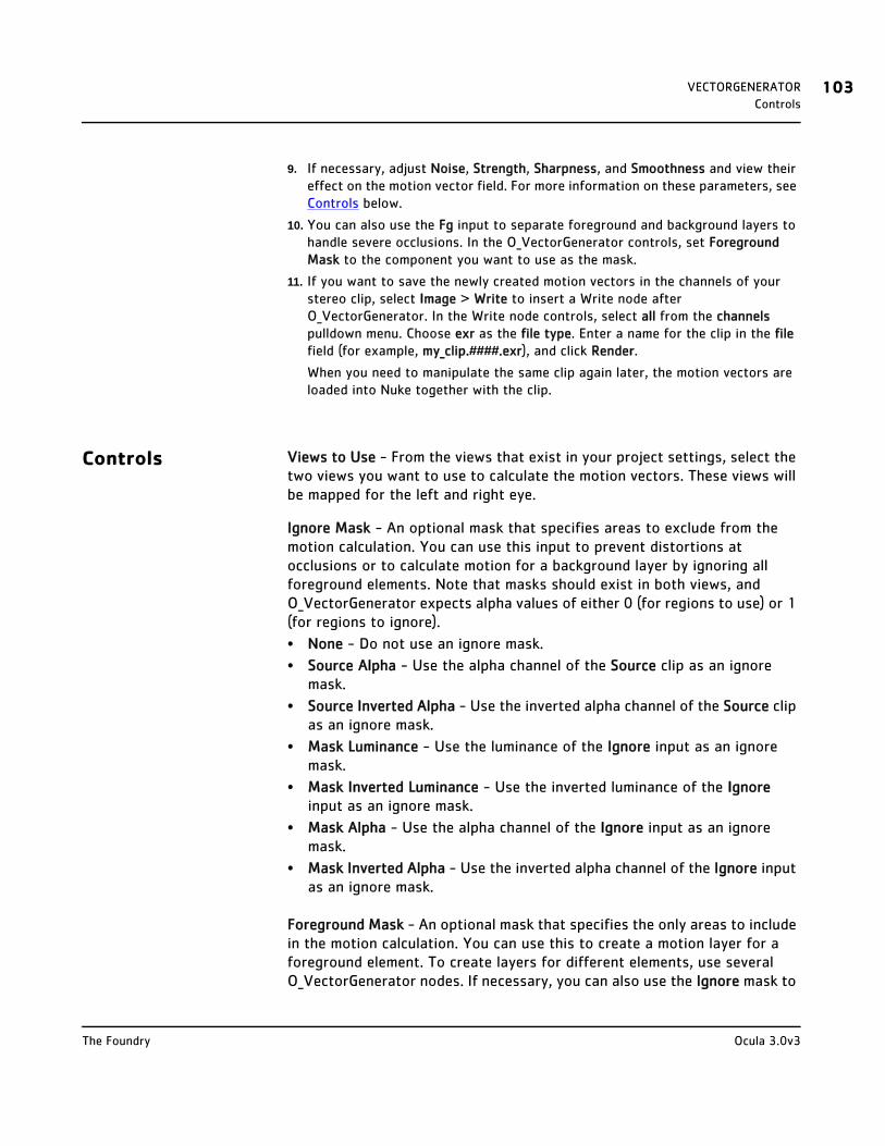
VECTORGENERATOR 103Controls
9. If necessary, adjust Noise, Strength, Sharpness, and Smoothness and view their effect on the motion vector field. For more information on these parameters, see Controls below.
10. You can also use the Fg input to separate foreground and background layers to handle severe occlusions. In the O_VectorGenerator controls, set Foreground Mask to the component you want to use as the mask.
11. If you want to save the newly created motion vectors in the channels of your stereo clip, select Image > Write to insert a Write node after O_VectorGenerator. In the Write node controls, select all from the channels pulldown menu. Choose exr as the file type. Enter a name for the clip in the file field (for example, my_clip.####.exr), and click Render.
When you need to manipulate the same clip again later, the motion vectors are loaded into Nuke together with the clip.
Controls Views to Use - From the views that exist in your project settings, select the two views you want to use to calculate the motion vectors. These views will be mapped for the left and right eye.
Ignore Mask - An optional mask that specifies areas to exclude from the motion calculation. You can use this input to prevent distortions at occlusions or to calculate motion for a background layer by ignoring all foreground elements. Note that masks should exist in both views, and O_VectorGenerator expects alpha values of either 0 (for regions to use) or 1 (for regions to ignore).
• None - Do not use an ignore mask.
• Source Alpha - Use the alpha channel of the Source clip as an ignore mask.
• Source Inverted Alpha - Use the inverted alpha channel of the Source clip as an ignore mask.
• Mask Luminance - Use the luminance of the Ignore input as an ignore mask.
• Mask Inverted Luminance - Use the inverted luminance of the Ignore input as an ignore mask.
• Mask Alpha - Use the alpha channel of the Ignore input as an ignore mask.
• Mask Inverted Alpha - Use the inverted alpha channel of the Ignore input as an ignore mask.
Foreground Mask - An optional mask that specifies the only areas to include in the motion calculation. You can use this to create a motion layer for a foreground element. To create layers for different elements, use several O_VectorGenerator nodes. If necessary, you can also use the Ignore mask to
Ocula 3.0v3The Foundry
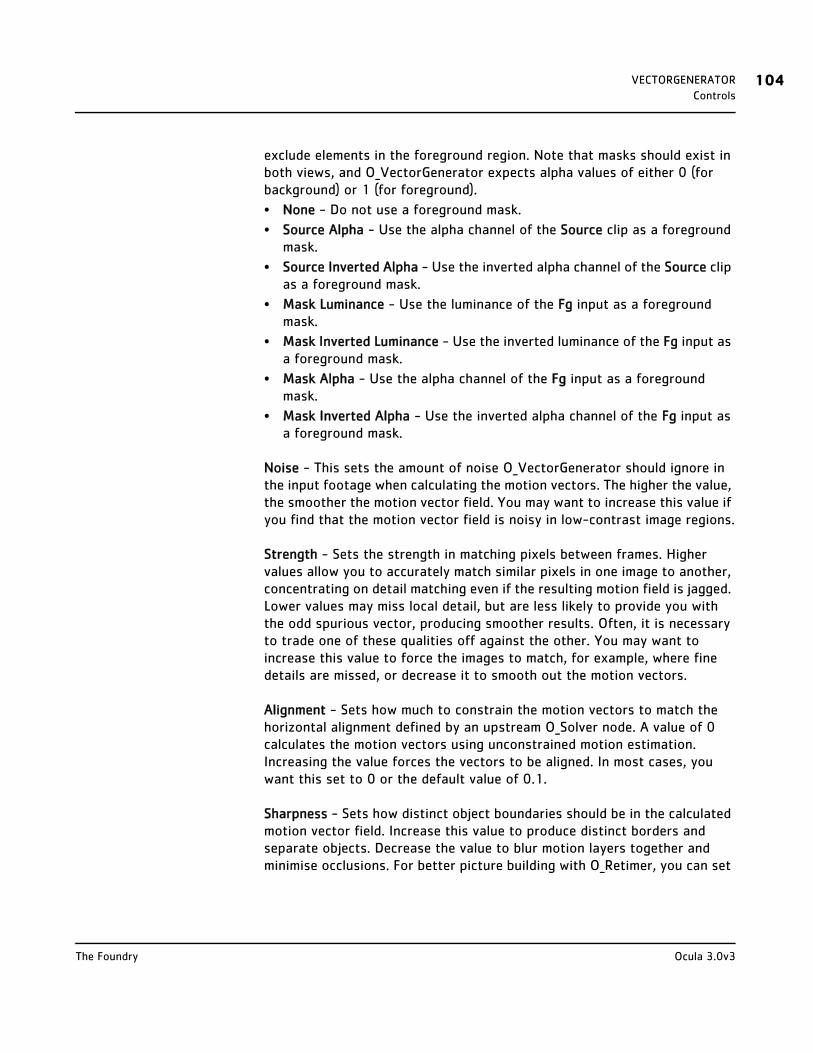
VECTORGENERATOR 104Controls
exclude elements in the foreground region. Note that masks should exist in both views, and O_VectorGenerator expects alpha values of either 0 (for background) or 1 (for foreground).
• None - Do not use a foreground mask.
• Source Alpha - Use the alpha channel of the Source clip as a foreground mask.
• Source Inverted Alpha - Use the inverted alpha channel of the Source clip as a foreground mask.
• Mask Luminance - Use the luminance of the Fg input as a foreground mask.
• Mask Inverted Luminance - Use the inverted luminance of the Fg input as a foreground mask.
• Mask Alpha - Use the alpha channel of the Fg input as a foreground mask.
• Mask Inverted Alpha - Use the inverted alpha channel of the Fg input as a foreground mask.
Noise - This sets the amount of noise O_VectorGenerator should ignore in the input footage when calculating the motion vectors. The higher the value, the smoother the motion vector field. You may want to increase this value if you find that the motion vector field is noisy in low-contrast image regions.
Strength - Sets the strength in matching pixels between frames. Higher values allow you to accurately match similar pixels in one image to another, concentrating on detail matching even if the resulting motion field is jagged. Lower values may miss local detail, but are less likely to provide you with the odd spurious vector, producing smoother results. Often, it is necessary to trade one of these qualities off against the other. You may want to increase this value to force the images to match, for example, where fine details are missed, or decrease it to smooth out the motion vectors.
Alignment - Sets how much to constrain the motion vectors to match the horizontal alignment defined by an upstream O_Solver node. A value of 0 calculates the motion vectors using unconstrained motion estimation. Increasing the value forces the vectors to be aligned. In most cases, you want this set to 0 or the default value of 0.1.
Sharpness - Sets how distinct object boundaries should be in the calculated motion vector field. Increase this value to produce distinct borders and separate objects. Decrease the value to blur motion layers together and minimise occlusions. For better picture building with O_Retimer, you can set
Ocula 3.0v3The Foundry
VECTORGENERATOR 105Example
this value to 0.
Smoothness - Applies extra smoothing to the motion vector field as a post process after image matching. The higher the value, the smoother the result. You can use this in conjunction with the Sharpness parameter to smooth out the motion vector field separately for distinct objects in the shot.
Example See page 109 for an example of how to use O_VectorGenerator and O_Retimer to calculate a motion vector field for a stereo image and use it to retime the sequence.
Figure 143. Sharpness set to 0. Figure 144. Sharpness set to 1.
Ocula 3.0v3The Foundry
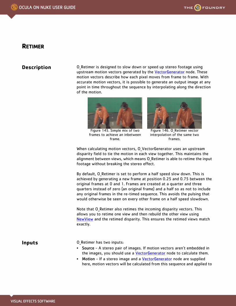
RETIMER
Description O_Retimer is designed to slow down or speed up stereo footage using upstream motion vectors generated by the VectorGenerator node. These motion vectors describe how each pixel moves from frame to frame. With accurate motion vectors, it is possible to generate an output image at any point in time throughout the sequence by interpolating along the direction of the motion.
When calculating motion vectors, O_VectorGenerator uses an upstream disparity field to tie the motion in each view together. This maintains the alignment between views, which means O_Retimer is able to retime the input footage without breaking the stereo effect.
By default, O_Retimer is set to perform a half speed slow down. This is achieved by generating a new frame at position 0.25 and 0.75 between the original frames at 0 and 1. Frames are created at a quarter and three quarters instead of zero (an original frame) and a half so as not to include any original frames in the re-timed sequence. This avoids the pulsing that would otherwise be seen on every other frame on a half speed slowdown.
Note that O_Retimer also retimes the incoming disparity vectors. This allows you to retime one view and then rebuild the other view using NewView and the retimed disparity. This ensures the retimed views match exactly.
Inputs O_Retimer has two inputs:
• Source - A stereo pair of images. If motion vectors aren’t embedded in the images, you should use a VectorGenerator node to calculate them.
• Motion - If a stereo image and a VectorGenerator node are supplied here, motion vectors will be calculated from this sequence and applied to
Figure 145. Simple mix of two frames to achieve an inbetween
frame.
Figure 146. O_Retimer vector interpolation of the same two
frames.
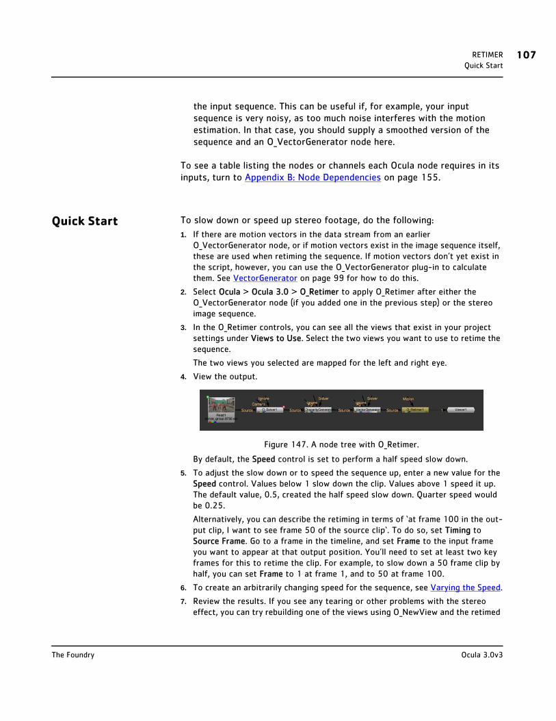
RETIMER 107Quick Start
the input sequence. This can be useful if, for example, your input sequence is very noisy, as too much noise interferes with the motion estimation. In that case, you should supply a smoothed version of the sequence and an O_VectorGenerator node here.
To see a table listing the nodes or channels each Ocula node requires in its inputs, turn to Appendix B: Node Dependencies on page 155.
Quick Start To slow down or speed up stereo footage, do the following:
1. If there are motion vectors in the data stream from an earlier O_VectorGenerator node, or if motion vectors exist in the image sequence itself, these are used when retiming the sequence. If motion vectors don’t yet exist in the script, however, you can use the O_VectorGenerator plug-in to calculate them. See VectorGenerator on page 99 for how to do this.
2. Select Ocula > Ocula 3.0 > O_Retimer to apply O_Retimer after either the O_VectorGenerator node (if you added one in the previous step) or the stereo image sequence.
3. In the O_Retimer controls, you can see all the views that exist in your project settings under Views to Use. Select the two views you want to use to retime the sequence.
The two views you selected are mapped for the left and right eye.
4. View the output.
Figure 147. A node tree with O_Retimer.
By default, the Speed control is set to perform a half speed slow down.
5. To adjust the slow down or to speed the sequence up, enter a new value for the Speed control. Values below 1 slow down the clip. Values above 1 speed it up. The default value, 0.5, created the half speed slow down. Quarter speed would be 0.25.
Alternatively, you can describe the retiming in terms of ‘at frame 100 in the out-put clip, I want to see frame 50 of the source clip‘. To do so, set Timing to Source Frame. Go to a frame in the timeline, and set Frame to the input frame you want to appear at that output position. You’ll need to set at least two key frames for this to retime the clip. For example, to slow down a 50 frame clip by half, you can set Frame to 1 at frame 1, and to 50 at frame 100.
6. To create an arbitrarily changing speed for the sequence, see Varying the Speed.
7. Review the results. If you see any tearing or other problems with the stereo effect, you can try rebuilding one of the views using O_NewView and the retimed
Ocula 3.0v3The Foundry
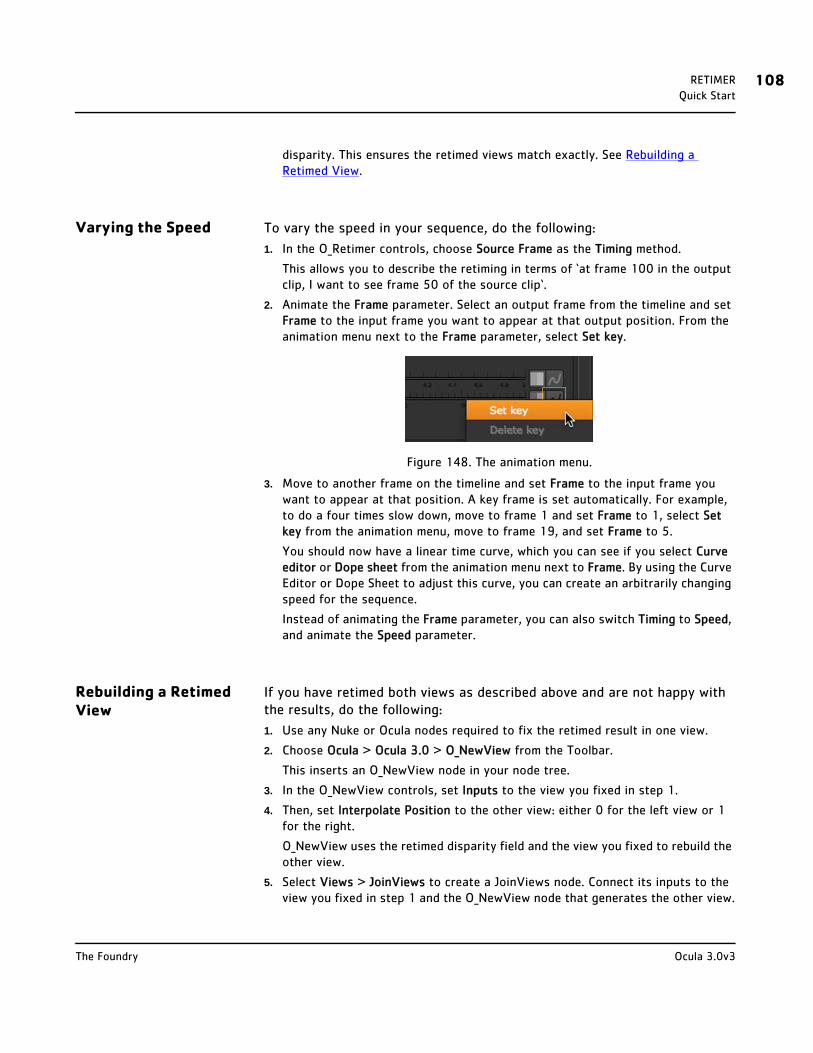
RETIMER 108Quick Start
disparity. This ensures the retimed views match exactly. See Rebuilding a Retimed View.
Varying the Speed To vary the speed in your sequence, do the following:
1. In the O_Retimer controls, choose Source Frame as the Timing method.
This allows you to describe the retiming in terms of ‘at frame 100 in the output clip, I want to see frame 50 of the source clip‘.
2. Animate the Frame parameter. Select an output frame from the timeline and set Frame to the input frame you want to appear at that output position. From the animation menu next to the Frame parameter, select Set key.
Figure 148. The animation menu.
3. Move to another frame on the timeline and set Frame to the input frame you want to appear at that position. A key frame is set automatically. For example, to do a four times slow down, move to frame 1 and set Frame to 1, select Set key from the animation menu, move to frame 19, and set Frame to 5.
You should now have a linear time curve, which you can see if you select Curve editor or Dope sheet from the animation menu next to Frame. By using the Curve Editor or Dope Sheet to adjust this curve, you can create an arbitrarily changing speed for the sequence.
Instead of animating the Frame parameter, you can also switch Timing to Speed, and animate the Speed parameter.
Rebuilding a Retimed View
If you have retimed both views as described above and are not happy with the results, do the following:
1. Use any Nuke or Ocula nodes required to fix the retimed result in one view.
2. Choose Ocula > Ocula 3.0 > O_NewView from the Toolbar.
This inserts an O_NewView node in your node tree.
3. In the O_NewView controls, set Inputs to the view you fixed in step 1.
4. Then, set Interpolate Position to the other view: either 0 for the left view or 1 for the right.
O_NewView uses the retimed disparity field and the view you fixed to rebuild the other view.
5. Select Views > JoinViews to create a JoinViews node. Connect its inputs to the view you fixed in step 1 and the O_NewView node that generates the other view.
Ocula 3.0v3The Foundry
RETIMER 109Controls
JoinViews combines these into a stereo output.
6. Connect a Viewer to the JoinViews node to view the result.
Controls Views to Use - From the views that exist in your project settings, select the two views you want to use to retime the clip. These views will be mapped for the left and right eye.
Timing - Sets how to control the new timing of the clip.
• Speed - select this if you wish to describe the retiming in terms of overall duration: double speed will halve the duration of the clip or half speed will double the duration of the clip.
• Source Frame - select this if you wish to describe the retiming in terms of ‘at frame 100 in the output clip, I want to see frame 50 of the source clip‘. You’ll need to set at least two keyframes for this to retime the clip.
Speed - Values below 1 slow down the clip. Values above 1 speed up movement. For example, to slow down the clip by a factor of two (half speed), set this value to 0.5. Quarter speed would be 0.25. This parameter is only active if Timing is set to Speed.
Frame - Use this to specify the source frame at the current frame in the timeline. For example, to slow down a 50 frame clip by half set the Source Frame to 1 at frame 1 and the Source Frame to 50 at frame 100. The default expression will result in a half-speed retime. This parameter is active only if Timing is set to Source Frame.
Warp Mode - Select a method to use to generate the retimed views.
• Simple - This mode warps and blends the images.
• Normal - This mode warps and blends the images where they are consistent.
• Occlusions - This mode may improve the results with large motion vectors.
• Sharp Occlusions - This mode is designed to reduce artefacts with a CG source where boundaries are distinct.
Example In this example, we generate motion vectors using O_VectorGenerator and feed them to O_Retimer in order to slow down and then speed up a stereo sequence.
You can download the image used here from our web site. For more
Ocula 3.0v3The Foundry

RETIMER 110Example
information, please see Example Images on page 6.
Step by Step Generating Motion Vectors
1. Start Nuke and open the project settings by pressing S on the Node Graph. Go to the Views tab and click the Set up views for stereo button.
2. Import dance_group.##.exr. This image already includes both the left and the right view and the necessary disparity channels.
3. Add a Viewer to the image.
4. Select Ocula > Ocula 3.0 > O_Solver to insert an O_Solver node between the image and the Viewer.
Figure 149. The node tree with O_Solver.
In order to calculate motion vectors, you always need an O_Solver node in the data stream, even if you have disparity channels embedded in the input image like we do here. If the disparity channels didn’t yet exist, you’d also need an O_DisparityGenerator node.
5. Scrub to frame 1 on the timeline and click Add Key in the O_Solver controls.
O_Solver calculates the camera relationship between the two views.
6. Insert an O_VectorGenerator node after O_Solver.
Figure 150. The node tree at this point.
The purpose of O_VectorGenerator is to calculate the motion vectors required later for retiming the sequence. Because we have disparity vectors in the data stream, O_VectorGenerator can do this in a way that maintains the alignment between views and avoids breaking the stereo effect.
7. In the Viewer, set the channel set menu to motion.
The calculated motion vectors are displayed in the Viewer.
Ocula 3.0v3The Foundry
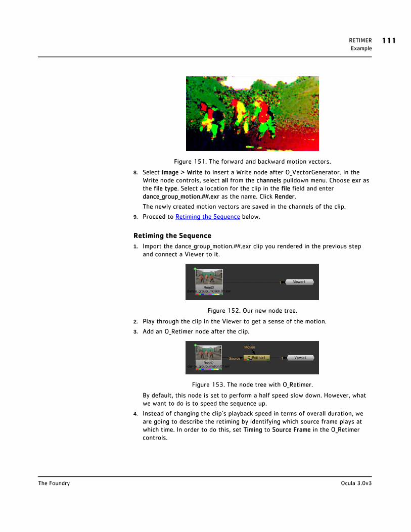
RETIMER 111Example
Figure 151. The forward and backward motion vectors.
8. Select Image > Write to insert a Write node after O_VectorGenerator. In the Write node controls, select all from the channels pulldown menu. Choose exr as the file type. Select a location for the clip in the file field and enter dance_group_motion.##.exr as the name. Click Render.
The newly created motion vectors are saved in the channels of the clip.
9. Proceed to Retiming the Sequence below.
Retiming the Sequence
1. Import the dance_group_motion.##.exr clip you rendered in the previous step and connect a Viewer to it.
Figure 152. Our new node tree.
2. Play through the clip in the Viewer to get a sense of the motion.
3. Add an O_Retimer node after the clip.
Figure 153. The node tree with O_Retimer.
By default, this node is set to perform a half speed slow down. However, what we want to do is to speed the sequence up.
4. Instead of changing the clip’s playback speed in terms of overall duration, we are going to describe the retiming by identifying which source frame plays at which time. In order to do this, set Timing to Source Frame in the O_Retimer controls.
Ocula 3.0v3The Foundry

RETIMER 112Example
Notice that the Speed field is grayed-out and the Frame field is activated. The default Frame setting is 1, which sets the first frame on the timeline to frame 1 of the input image.
In order to retime a clip using Source Frame retiming, you need to set at least two keyframes.
5. Click the animation menu next to Frame and select Set key in order to set a keyframe at the first frame on the timeline.
Figure 154. The animation menu.
The Frame field turns blue to indicate a keyframe has been set.
6. Move the playhead to frame 8 and set the Frame value to 4. A keyframe is set automatically.
O_Retimer sets frame 8 on the timeline to frame 4 of the input image, effectively reducing the playback speed by half leading up to frame 8.
7. Move the playhead to frame 15 and set the Frame value to 15.
O_Retimer sets frame 15 on the timeline to the last frame of the input clip, effectively returning the playback speed to normal at frame 15.
8. Press Play in the Viewer to process and review the results.
Once the process has completed, you should be able to see the result of the retime. In reality, the length of the clip is a little too short to see it clearly.
9. Return to the beginning of the clip and play through each frame with the Next Frame arrow in the Viewer. You should notice that the Frame value changes over time - slowly up to frame 8 and more quickly towards the final frame.
Figure 155. The retime in the Curve Editor.
Ocula 3.0v3The Foundry

DEPTHTODISPARITY
Description Many Ocula plug-ins rely on disparity fields to produce their output. Usually, disparity fields are created using a combination of the O_Solver (see page 18) and O_DisparityGenerator (see page 32) nodes.
However, if you have a CG scene with stereo camera information and z-depth map available, you can also use the O_DepthToDisparity plug-in to generate the disparity field. Provided that the camera information and z-depth map are correct, this is both faster and more accurate than using the O_Solver and O_DisparityGenerator nodes.
Generating a Disparity Field
Using one of the camera transforms and the corresponding depth map, O_DepthToDisparity does a back projection from one view to find the position of each image point in 3D space. It then projects this point with the other camera transform to find the position of the point in the other view. The difference between the two positions gives the disparity in one direction.
As with the O_DisparityGenerator plug-in, the final disparity vectors are stored in disparity channels, so you might not see any image data appear when you first calculate the disparity field. To see the output inside Nuke, select the disparity channels from the channel set and channel controls in the top left corner of the Viewer. An example of what a disparity channel might look like is shown on page 36.
Once you have generated a disparity field that describes the relation between the views of a particular clip well, it will be suitable for use in most of the Ocula plug-ins. We recommend that you insert a Write node after O_DepthToDisparity to render the original images and the disparity channels as a stereo .exr file. This format allows for the storage of an image with multiple views and channel sets embedded in it. Later, whenever you use the same image sequence, the disparity field will be loaded into Nuke together with the sequence and is readily available for the Ocula plug-ins. For information on how to generate a disparity field using O_DepthToDisparity and render it as an .exr file, see page 114.
Note To use O_DepthToDisparity, you do need the positions of the stereo camera rig for the two views.

DEPTHTODISPARITY 114Inputs
Inputs O_DepthToDisparity has got two inputs:
• Depth - This is a stereo pair of images (usually, a scene you’ve rendered from a 3D application). In the depth channel, there should be a z-depth map for each view.
If this input is an .exr file, the z-depth map may already be embedded in the clip.
If you’re using another file format and have saved the depth map as a separate image, you can use a Nuke Shuffle node (Channel > Shuffle) to get the z-depth map in the depth channel of the Depth image. For infor-mation on how to do this, see the Nuke user guide.
• Camera - A Nuke stereo Camera node. This is the camera the scene was rendered with. In most cases, you would import this into Nuke from a third-party 3D application. For information on how to do this, see the Nuke user guide.
Tip In Nuke, a stereo camera can be either:
• a single Camera node in which some or all of the controls are split (Figure 156), or
• two Camera nodes (one for each view) followed by a JoinViews node (Views > JoinViews). The JoinViews node combines the two cameras into a single output
(Figure 157).
To see a table listing the nodes or channels each Ocula node requires in its inputs, turn to Appendix B: Node Dependencies on page 155.
Quick Start To generate a disparity field for a stereo clip, do the following:
1. Start Nuke and press S on the Node Graph to open the project settings. Go to the Views tab and click the Set up views for stereo button.
2. From the Toolbar, select Image > Read to load your stereo clip (usually, a rendered 3D scene) into Nuke. If you don’t have both views in the same file, select Views > JoinViews to combine them, or use a variable in the Read node’s file field to replace the name of the view (use the variable %V to replace an
Figure 156. A single Camera node with split controls.
Figure 157. Two cameras combined using Nuke’s JoinViews node.
Ocula 3.0v3The Foundry
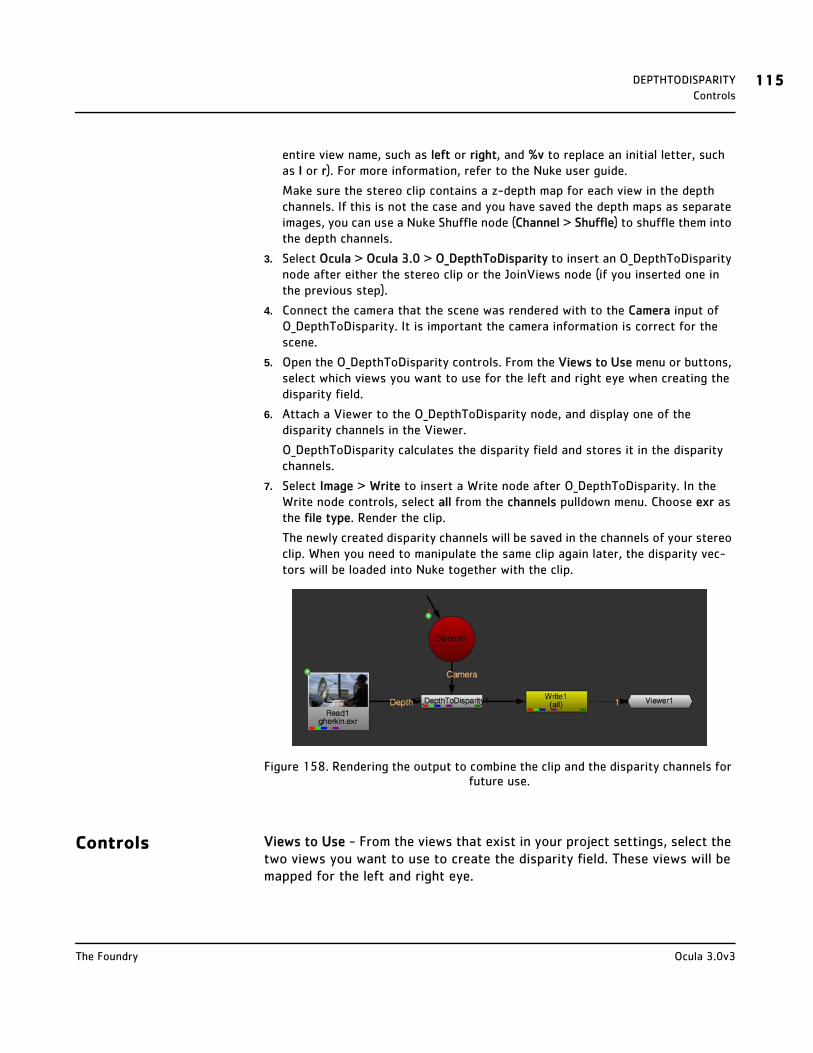
DEPTHTODISPARITY 115Controls
entire view name, such as left or right, and %v to replace an initial letter, such as l or r). For more information, refer to the Nuke user guide.
Make sure the stereo clip contains a z-depth map for each view in the depth channels. If this is not the case and you have saved the depth maps as separate images, you can use a Nuke Shuffle node (Channel > Shuffle) to shuffle them into the depth channels.
3. Select Ocula > Ocula 3.0 > O_DepthToDisparity to insert an O_DepthToDisparity node after either the stereo clip or the JoinViews node (if you inserted one in the previous step).
4. Connect the camera that the scene was rendered with to the Camera input of O_DepthToDisparity. It is important the camera information is correct for the scene.
5. Open the O_DepthToDisparity controls. From the Views to Use menu or buttons, select which views you want to use for the left and right eye when creating the disparity field.
6. Attach a Viewer to the O_DepthToDisparity node, and display one of the disparity channels in the Viewer.
O_DepthToDisparity calculates the disparity field and stores it in the disparity channels.
7. Select Image > Write to insert a Write node after O_DepthToDisparity. In the Write node controls, select all from the channels pulldown menu. Choose exr as the file type. Render the clip.
The newly created disparity channels will be saved in the channels of your stereo clip. When you need to manipulate the same clip again later, the disparity vec-tors will be loaded into Nuke together with the clip.
Figure 158. Rendering the output to combine the clip and the disparity channels for future use.
Controls Views to Use - From the views that exist in your project settings, select the two views you want to use to create the disparity field. These views will be mapped for the left and right eye.
Ocula 3.0v3The Foundry
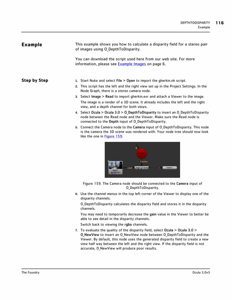
DEPTHTODISPARITY 116Example
Example This example shows you how to calculate a disparity field for a stereo pair of images using O_DepthToDisparity.
You can download the script used here from our web site. For more information, please see Example Images on page 6.
Step by Step 1. Start Nuke and select File > Open to import the gherkin.nk script.
2. This script has the left and the right view set up in the Project Settings. In the Node Graph, there is a stereo camera node.
3. Select Image > Read to import gherkin.exr and attach a Viewer to the image.
The image is a render of a 3D scene. It already includes the left and the right view, and a depth channel for both views.
4. Select Ocula > Ocula 3.0 > O_DepthToDisparity to insert an O_DepthToDisparity node between the Read node and the Viewer. Make sure the Read node is connected to the Depth input of O_DepthToDisparity.
5. Connect the Camera node to the Camera input of O_DepthToDisparity. This node is the camera the 3D scene was rendered with. Your node tree should now look like the one in Figure 159.
Figure 159. The Camera node should be connected to the Camera input of O_DepthToDisparity.
6. Use the channel menus in the top left corner of the Viewer to display one of the disparity channels.
O_DepthToDisparity calculates the disparity field and stores it in the disparity channels.
You may need to temporarily decrease the gain value in the Viewer to better be able to see detail in the disparity channels.
Switch back to viewing the rgba channels.
7. To evaluate the quality of the disparity field, select Ocula > Ocula 3.0 > O_NewView to insert an O_NewView node between O_DepthToDisparity and the Viewer. By default, this node uses the generated disparity field to create a new view half way between the left and the right view. If the disparity field is not accurate, O_NewView will produce poor results.
Ocula 3.0v3The Foundry

DEPTHTODISPARITY 117Example
Figure 160. Using O_NewView to test the generated disparity field.
8. In the O_NewView controls, set Warp Mode to Sharp Occlusions. This gives the best results when the disparity fields are generated from CG depth (see Figure 161 and Figure 162).
As you can see, O_NewView has used the disparity field from O_DepthToDisparity to produce a reasonably accurate new view. However, there seems to be a thin "halo" around some object outlines. This is a result of anti-aliasing on object boundaries. Because anti-aliasing mixes the colours of the background and foreground, O_NewView doesn't know which is the correct colour to use in these regions, and the results may need further editing.
It is worth noting, however, that the results achieved with O_DepthToDisparity are usually better than those achieved with O_Solver and O_DisparityGenerator. The difference is particularly clear when there are several occluded areas in the images due to wide camera separation.
Figure 161. Warp Mode set to Normal. Figure 162. Warp Mode set to Sharp Occlusions.
Ocula 3.0v3The Foundry

DISPARITYTODEPTH
Description The O_DisparityToDepth plug-in produces a z-depth map for each view of a stereo clip based on the clip’s disparity field and stereo camera setup.
A z-depth map is an image that uses the brightness of each pixel to specify the distance between the 3D scene point and the virtual camera used to capture the scene. You may need a z-depth map, for example, if you want to introduce fog and depth-of-field effects into a shot. In Nuke, the ZBlur node (Filter > ZBlur) requires a depth map in its input.
O_DisparityToDepth stores the final z-depth map in the depth channels, so you might not see any image data appear when you first calculate the depth map. To see the output inside Nuke, select the depth channels from the channel controls in the top left corner of the Viewer. An example of what a depth channel might look like is shown in Figure 163.
Figure 163. A depth map.
Inputs O_DisparityToDepth has two inputs:
• Source - This is a stereo pair of images. There should be a disparity field in the disparity channels. For information on how to embed a disparity field in an image this way, see DisparityGenerator on page 32.
• Camera - A pretracked Nuke stereo camera that describes the camera setup used to shoot the Source images. This can be a camera you have tracked with the CameraTracker node or imported to Nuke from a third-party camera tracking application.
Tip In Nuke, a stereo camera can be either:
• a single Camera node in which some or all of the controls are split (Figure 164), or

DISPARITYTODEPTH 119Quick Start
• two Camera nodes (one for each view) followed by a JoinViews node (Views > JoinViews). The JoinViews node combines the two cameras into a single output
(Figure 165).
To see a table listing the nodes or channels each Ocula node requires in its inputs, turn to Appendix B: Node Dependencies on page 155.
Quick Start To generate a z-depth map for a stereo clip, do the following:
1. If there are disparity vectors in the data stream from an earlier O_DisparityGenerator node, or if disparity vectors exist in the image sequence itself, these are used when generating the z-depth map. If disparity vectors don’t yet exist in the script, however, you can use the O_Solver and O_DisparityGenerator plug-ins after your image sequence to calculate the dis-parity vectors. See DisparityToDepth on page 118 and DisparityGenerator on page 32 for how to do this.
2. Select Ocula > Ocula 3.0 > O_DisparityToDepth to insert an O_DisparityToDepth node after either the O_DisparityGenerator node (if you added one in the previous step) or the image sequence.
3. Connect a pretracked Nuke stereo camera to the Camera input of O_DisparityToDepth.
4. Open the O_DisparityToDepth controls. From the Views to Use menu or buttons, select which views you want to use for the left and right eye when creating the z-depth map.
5. Attach a Viewer to the O_DisparityToDepth node, and display one of the depth channels in the Viewer.
6. Select Image > Write to insert a Write node after O_DisparityToDepth. In the Write node controls, select all from the channels pulldown menu. Choose exr as the file type. Render the clip.
The newly created depth channels will be saved in the channels of your stereo clip. When you need to manipulate the same clip again later, the z-depth maps will be loaded into Nuke together with the clip.
Figure 164. A single Camera node with split controls.
Figure 165. Two cameras combined using Nuke’s JoinViews node.
Ocula 3.0v3The Foundry
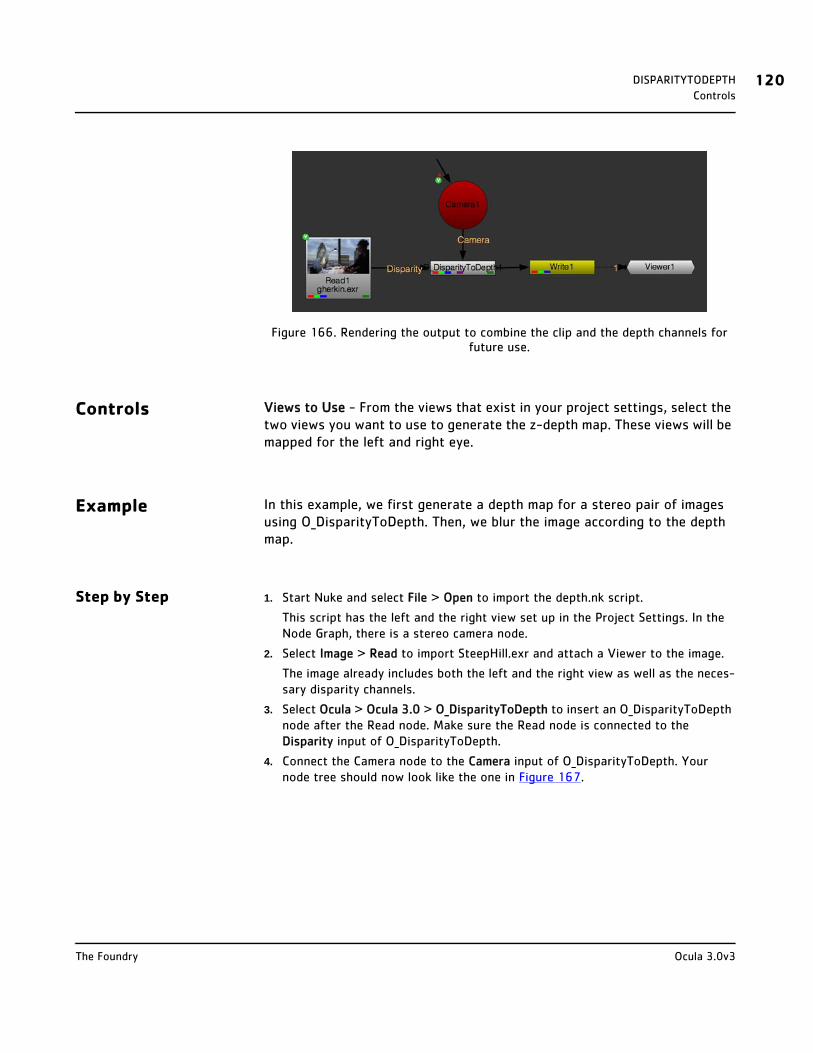
DISPARITYTODEPTH 120Controls
Figure 166. Rendering the output to combine the clip and the depth channels for future use.
Controls Views to Use - From the views that exist in your project settings, select the two views you want to use to generate the z-depth map. These views will be mapped for the left and right eye.
Example In this example, we first generate a depth map for a stereo pair of images using O_DisparityToDepth. Then, we blur the image according to the depth map.
Step by Step 1. Start Nuke and select File > Open to import the depth.nk script.
This script has the left and the right view set up in the Project Settings. In the Node Graph, there is a stereo camera node.
2. Select Image > Read to import SteepHill.exr and attach a Viewer to the image.
The image already includes both the left and the right view as well as the neces-sary disparity channels.
3. Select Ocula > Ocula 3.0 > O_DisparityToDepth to insert an O_DisparityToDepth node after the Read node. Make sure the Read node is connected to the Disparity input of O_DisparityToDepth.
4. Connect the Camera node to the Camera input of O_DisparityToDepth. Your node tree should now look like the one in Figure 167.
Ocula 3.0v3The Foundry
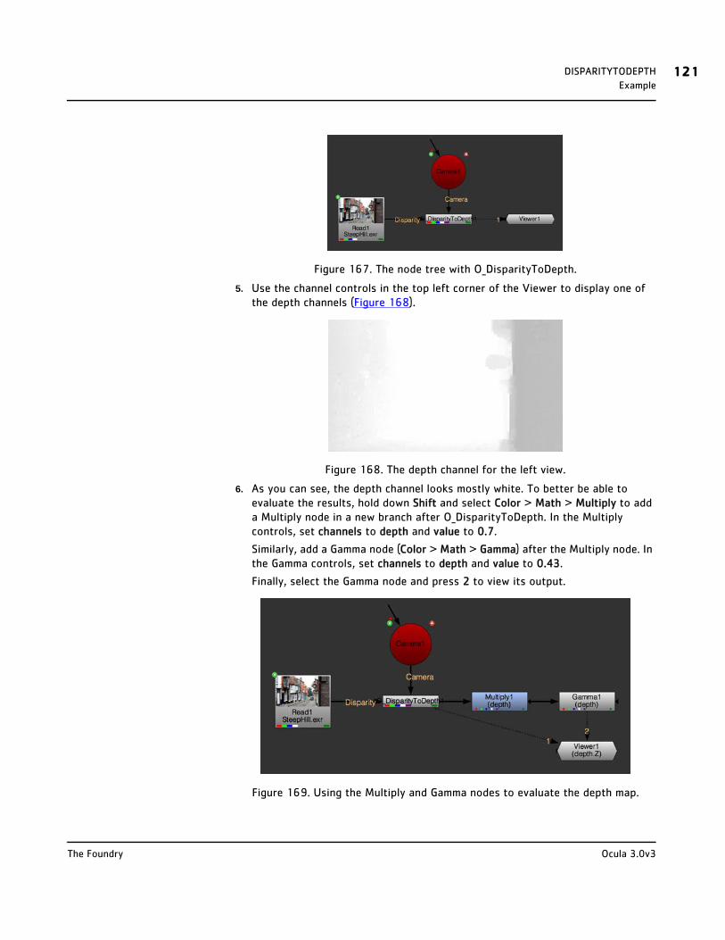
DISPARITYTODEPTH 121Example
Figure 167. The node tree with O_DisparityToDepth.
5. Use the channel controls in the top left corner of the Viewer to display one of the depth channels (Figure 168).
Figure 168. The depth channel for the left view.
6. As you can see, the depth channel looks mostly white. To better be able to evaluate the results, hold down Shift and select Color > Math > Multiply to add a Multiply node in a new branch after O_DisparityToDepth. In the Multiply controls, set channels to depth and value to 0.7.
Similarly, add a Gamma node (Color > Math > Gamma) after the Multiply node. In the Gamma controls, set channels to depth and value to 0.43.
Finally, select the Gamma node and press 2 to view its output.
Figure 169. Using the Multiply and Gamma nodes to evaluate the depth map.
Ocula 3.0v3The Foundry
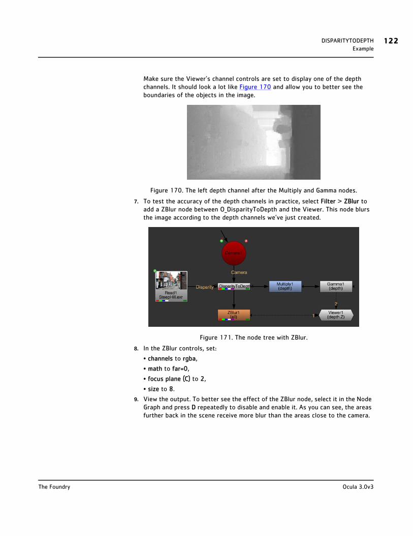
DISPARITYTODEPTH 122Example
Make sure the Viewer’s channel controls are set to display one of the depth channels. It should look a lot like Figure 170 and allow you to better see the boundaries of the objects in the image.
Figure 170. The left depth channel after the Multiply and Gamma nodes.
7. To test the accuracy of the depth channels in practice, select Filter > ZBlur to add a ZBlur node between O_DisparityToDepth and the Viewer. This node blurs the image according to the depth channels we’ve just created.
Figure 171. The node tree with ZBlur.
8. In the ZBlur controls, set:
• channels to rgba,
• math to far=0,
• focus plane (C) to 2,
• size to 8.
9. View the output. To better see the effect of the ZBlur node, select it in the Node Graph and press D repeatedly to disable and enable it. As you can see, the areas further back in the scene receive more blur than the areas close to the camera.
Ocula 3.0v3The Foundry

DISPARITYTODEPTH 123Example
Figure 172. The output of ZBlur.
10. If you are happy with the depth channels, you can save them in the channels of the input clip for later use. Select Image > Write to insert a Write node between O_DisparityToDepth and ZBlur. In the Write node controls, select all from the channels pulldown menu. Use the file control to give the file a location and a new name. Choose exr as the file type and click Render to render the image.
Ocula 3.0v3The Foundry
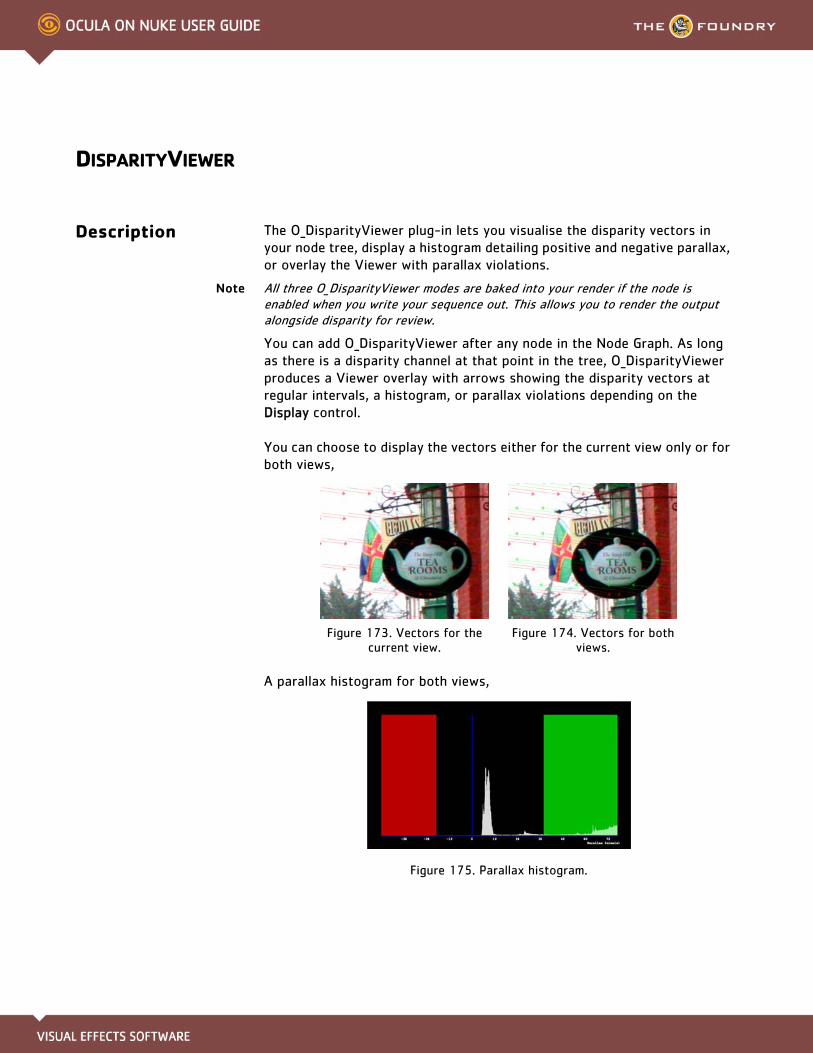
DISPARITYVIEWER
Description The O_DisparityViewer plug-in lets you visualise the disparity vectors in your node tree, display a histogram detailing positive and negative parallax, or overlay the Viewer with parallax violations.
Note All three O_DisparityViewer modes are baked into your render if the node is enabled when you write your sequence out. This allows you to render the output alongside disparity for review.
You can add O_DisparityViewer after any node in the Node Graph. As long as there is a disparity channel at that point in the tree, O_DisparityViewer produces a Viewer overlay with arrows showing the disparity vectors at regular intervals, a histogram, or parallax violations depending on the Display control.
You can choose to display the vectors either for the current view only or for both views,
A parallax histogram for both views,
Figure 175. Parallax histogram.
Figure 173. Vectors for the current view.
Figure 174. Vectors for both views.

DISPARITYVIEWER 125Inputs
Or a parallax violation overlay for the current view.
Figure 176. Parallax violation overlay.
You can also change the colour of the vectors, histogram, or overlays. This may be useful if you wish to compare disparity methods and have more than one O_DisparityViewer overlay displayed at once or if the background colour is similar to one of the default colours.
Inputs O_DisparityViewer has one input: Source - This is any node in the node tree with a disparity field in the disparity channels.
To see a table listing the nodes or channels each Ocula node requires in its inputs, turn to Appendix B: Node Dependencies on page 155.
Quick Start You can choose to display:
• Disparity Vectors,
• Parallax Histograms, or
• Histograms are baked into your render if the node is enabled when you write your sequence out..
Disparity Vectors To visualise the disparity vectors at any given point of your node tree, do the following:
1. Select a node at any point in the node tree where there is a disparity channel.
If you don’t have a disparity channel in the data stream, you can add one using the O_Solver and O_DisparityGenerator nodes. See Solver on page 18 and Dis-parityGenerator on page 32.
2. Choose Ocula > Ocula 3.0 > O_DisparityViewer from the Toolbar.
This inserts an O_DisparityViewer node in your node tree.
Ocula 3.0v3The Foundry

DISPARITYVIEWER 126Quick Start
3. Under Views to Use, select the views you want to use to visualise the disparity vectors. These views are mapped for the left and right eye.
4. Using the Display menu, select Disparity Vectors.
5. If you want to display the vectors for both views rather than just the current
view, check Show Both Directions.
6. Zoom in to better see the disparity vectors in the overlay.
7. If the Viewer seems too cluttered or the arrows overlap, increase the Vector
Spacing value.
8. If necessary, use the disparityR and disparityL parameters to change the colour of the arrows. You may want to do this, for example, if the default colour is very close to the colours in your input image, or if you want to compare disparity methods and have more than one O_DisparityViewer overlay displayed at once.
Note Disparity vectors are baked into your render if the node is enabled when you write your sequence out.
Parallax Histograms To view a parallax histogram for any given point of your node tree, do the following:
1. Select a node at any point in the node tree where there is a disparity channel.
Figure 177. Vectors for the current view.
Figure 178. Vectors for both views.
Figure 179. Vector Spacing set to 30.
Figure 180. Vector Spacing set to 70.
Ocula 3.0v3The Foundry
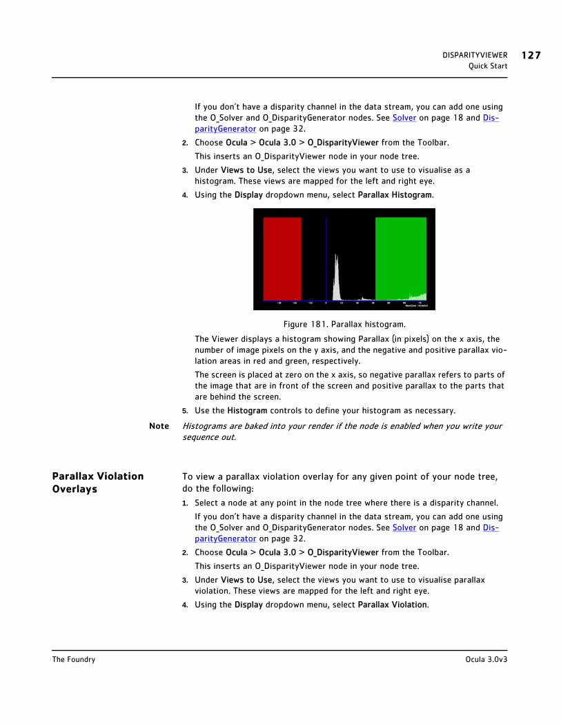
DISPARITYVIEWER 127Quick Start
If you don’t have a disparity channel in the data stream, you can add one using the O_Solver and O_DisparityGenerator nodes. See Solver on page 18 and Dis-parityGenerator on page 32.
2. Choose Ocula > Ocula 3.0 > O_DisparityViewer from the Toolbar.
This inserts an O_DisparityViewer node in your node tree.
3. Under Views to Use, select the views you want to use to visualise as a histogram. These views are mapped for the left and right eye.
4. Using the Display dropdown menu, select Parallax Histogram.
Figure 181. Parallax histogram.
The Viewer displays a histogram showing Parallax (in pixels) on the x axis, the number of image pixels on the y axis, and the negative and positive parallax vio-lation areas in red and green, respectively.
The screen is placed at zero on the x axis, so negative parallax refers to parts of the image that are in front of the screen and positive parallax to the parts that are behind the screen.
5. Use the Histogram controls to define your histogram as necessary.
Note Histograms are baked into your render if the node is enabled when you write your sequence out.
Parallax Violation Overlays
To view a parallax violation overlay for any given point of your node tree, do the following:
1. Select a node at any point in the node tree where there is a disparity channel.
If you don’t have a disparity channel in the data stream, you can add one using the O_Solver and O_DisparityGenerator nodes. See Solver on page 18 and Dis-parityGenerator on page 32.
2. Choose Ocula > Ocula 3.0 > O_DisparityViewer from the Toolbar.
This inserts an O_DisparityViewer node in your node tree.
3. Under Views to Use, select the views you want to use to visualise parallax violation. These views are mapped for the left and right eye.
4. Using the Display dropdown menu, select Parallax Violation.
Ocula 3.0v3The Foundry

DISPARITYVIEWER 128Controls
Figure 182. Parallax violation overlay.
The parallax violation overlay appears in the Viewer, highlighting the areas of negative and positive parallax violation - that is, areas outside the limits speci-fied in the Negative Violation and Positive Violation controls.
5. Use the Parallax controls to define your overlay parameters as necessary.
Note Parallax violation overlays are baked into your render if the node is enabled when you write your sequence out.
Controls Views to Use - From the views that exist in your project settings, select the two views you want to use when visualising the disparity vectors. These views will be mapped for the left and right eye.
Display - Select the display mode from the dropdown menu:
• Disparity Vectors - overlays the disparity vectors for the current view.
• Parallax Histogram - displays a parallax by pixel histogram.
• Parallax Violation - overlays negative and positive parallax areas.
Vectors
disparityR - Colour of the arrows used for displaying left-to-right disparity. You may want to change this, for example, if the colour of the arrows is very close to the colours in your input image, or if you want to compare the vectors from multiple O_DisparityViewers in the same Viewer.
disparityL - Colour of the arrows used for displaying right-to-left disparity. You may want to change this, for example, if the colour of the arrows is very close to the colours in your input image, or if you want to compare the vectors from multiple O_DisparityViewers in the same Viewer.
Show Both Directions - Check this to show the disparity vectors for both views rather than just the current view.
Ocula 3.0v3The Foundry

DISPARITYVIEWER 129Controls
Vector Spacing - How often a disparity vector will be drawn. If necessary, you can increase this value to make the display less cluttered. You may want to do so, for example, if the disparities are large and you don’t want neighbouring vectors to overlap one another.
Histogram
Histogram Range - Use this menu to select the histogram range:
• Automatic - the range is scaled to fit the range of disparity.
• User Defined - the range is defined using the Histogram Min and Max controls as a percentage of screen width.
Histogram Min/Max - Controls the lower and upper limits of the histogram as a percentage of screen width, that is, the left-most and right-most points on the x axis.
Note These controls are only active when Histogram Range is set to User Defined.
Parallax
Negative Limit - Sets the amount of negative parallax allowed as a percentage of screen width. Areas outside this negative limit are marked by the overlay in the colour specified in the Negative Violation control.
Pixels - Displays the number of pixels allowed by negative parallax. After adjusting the Negative Limit, you can use this corresponding value in the O_DisparityGenerator Parallax Limits > Negative control.
Positive Limit - Sets the amount of positive parallax allowed as a percentage of screen width. Areas outside this positive limit are marked by the overlay in the colour specified in the Positive Violation control.
Pixels - Displays the number of pixels allowed by positive parallax. After adjusting the Positive Limit, you can use this corresponding value in the O_DisparityGenerator Parallax Limits > Positive control.
Negative Violation - Sets the overlay colour for pixels outside the specified Negative Limit value.
Positive Violation - Sets the overlay colour for pixels outside the specified Positive Limit value.
Ocula 3.0v3The Foundry
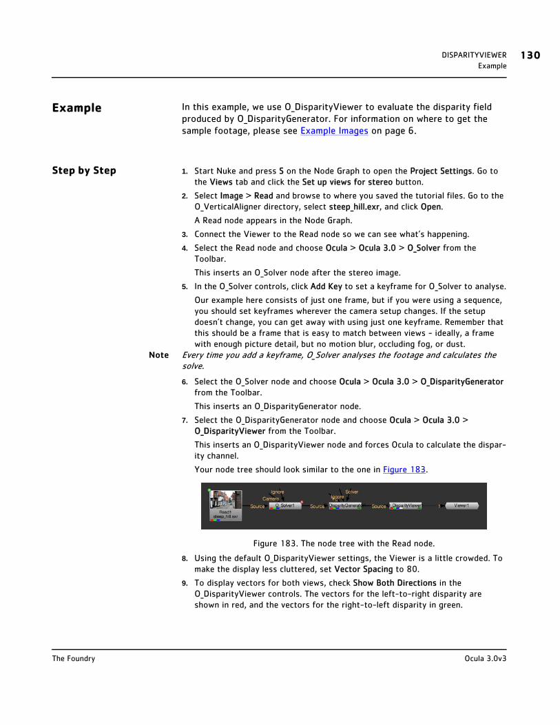
DISPARITYVIEWER 130Example
Example In this example, we use O_DisparityViewer to evaluate the disparity field produced by O_DisparityGenerator. For information on where to get the sample footage, please see Example Images on page 6.
Step by Step 1. Start Nuke and press S on the Node Graph to open the Project Settings. Go to the Views tab and click the Set up views for stereo button.
2. Select Image > Read and browse to where you saved the tutorial files. Go to the O_VerticalAligner directory, select steep_hill.exr, and click Open.
A Read node appears in the Node Graph.
3. Connect the Viewer to the Read node so we can see what’s happening.
4. Select the Read node and choose Ocula > Ocula 3.0 > O_Solver from the Toolbar.
This inserts an O_Solver node after the stereo image.
5. In the O_Solver controls, click Add Key to set a keyframe for O_Solver to analyse.
Our example here consists of just one frame, but if you were using a sequence, you should set keyframes wherever the camera setup changes. If the setup doesn’t change, you can get away with using just one keyframe. Remember that this should be a frame that is easy to match between views - ideally, a frame with enough picture detail, but no motion blur, occluding fog, or dust.
Note Every time you add a keyframe, O_Solver analyses the footage and calculates the solve.
6. Select the O_Solver node and choose Ocula > Ocula 3.0 > O_DisparityGenerator from the Toolbar.
This inserts an O_DisparityGenerator node.
7. Select the O_DisparityGenerator node and choose Ocula > Ocula 3.0 > O_DisparityViewer from the Toolbar.
This inserts an O_DisparityViewer node and forces Ocula to calculate the dispar-ity channel.
Your node tree should look similar to the one in Figure 183.
Figure 183. The node tree with the Read node.
8. Using the default O_DisparityViewer settings, the Viewer is a little crowded. To make the display less cluttered, set Vector Spacing to 80.
9. To display vectors for both views, check Show Both Directions in the O_DisparityViewer controls. The vectors for the left-to-right disparity are shown in red, and the vectors for the right-to-left disparity in green.
Ocula 3.0v3The Foundry

DISPARITYVIEWER 131Example
Figure 184. Disparity vectors.
This sample footage does not produce good disparity vectors.
The purpose of this tutorial is to show you how to use the Parallax Histogram and Parallax Violation display modes.
10. In the O_DisparityViewer controls, click on the Display dropdown menu and select Parallax Histogram.
The Viewer displays a histogram showing Parallax (in pixels) on the x axis, the number of image pixels on the y axis, and the negative and positive parallax vio-lation areas in red and green, respectively.
Note The screen is placed at zero on the x axis, so negative parallax refers to parts of the image that are in front of the screen and positive parallax to the parts that are behind the screen.
Figure 185. Parallax histogram.
Histogram Range defaults to User Defined, so the graph produced may not con-tain all the pixels in the image.
11. Click the Histogram Range menu and select Automatic.
The histogram is re-rendered to automatically fit the range of disparities in the image.
Ocula 3.0v3The Foundry
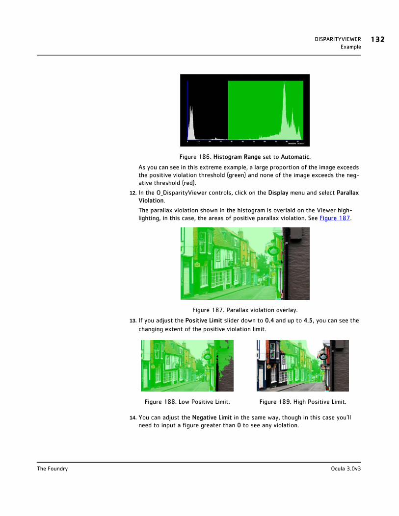
DISPARITYVIEWER 132Example
Figure 186. Histogram Range set to Automatic.
As you can see in this extreme example, a large proportion of the image exceeds the positive violation threshold (green) and none of the image exceeds the neg-ative threshold (red).
12. In the O_DisparityViewer controls, click on the Display menu and select Parallax Violation.
The parallax violation shown in the histogram is overlaid on the Viewer high-lighting, in this case, the areas of positive parallax violation. See Figure 187.
Figure 187. Parallax violation overlay.
13. If you adjust the Positive Limit slider down to 0.4 and up to 4.5, you can see the
changing extent of the positive violation limit.
14. You can adjust the Negative Limit in the same way, though in this case you’ll need to input a figure greater than 0 to see any violation.
Figure 188. Low Positive Limit. Figure 189. High Positive Limit.
Ocula 3.0v3The Foundry

DISPARITYVIEWER 133Example
Figure 190. Positive and negative parallax violations.
15. Once you’ve set your Limits, you can read off the negative and positive Pixels values for Parallax Limits and force apply them to the image by opening up the O_DisparityGenerator and enabling Enforce parallax limits.
Figure 191. Pixels values.
See DisparityGenerator on page 32 for more information.
Ocula 3.0v3The Foundry
APPENDIX A: RELEASE NOTES
This section describes the requirements, new features, improvements, fixed bugs, known bugs, and workarounds for each release of Ocula.
Ocula 3.0v3 This release adds support for Nuke 7.0 and contains two improvements.
Release Date
December 2012
Minimum System Requirements
• A version of Nuke 6.3 or 7.0 on:
• Windows XP Professional x64 Edition or Windows 7 Home Premium x64
• Mac OS X 10.5 “Leopard” (Nuke 6.3 only), 10.6 “Snow Leopard”, or 10.7 “Lion” (Nuke 7.0 only), 64-bit
• Linux RHEL 5.4 for Intel64 or AMD64
Note Mac OS X 10.8 “Mountain Lion” is currently not supported as an operating system for Nuke.
• Foundry Licensing Tools (FLT 7.0v2 or later) for floating licenses.
New FeaturesThere are no new features in this release.
Improvements
• BUG ID 22779 - Output from all Ocula nodes is now cached to prevent recalculation, improving the usability of Ocula node trees considerably.
• BUG ID 32272 - O_DisparityGenerator and O_VectorGenerator now have a Noise parameter. This sets the amount of noise these nodes should ignore in the input footage when calculating their results. The higher the value, the smoother the results. You may want to increase this value if you find that your disparity or motion vector field is noisy in low-contrast image regions.
Fixed Bugs
• BUG ID 24486 - O_DisparityGenerator: Connecting inputs with different bounding boxes caused Nuke to crash.
APPENDIX A: RELEASE NOTES 135Ocula 3.0v3
• BUG ID 26425 - The disparity channel was cropped to the bounding box even when rgba data existed outside the bounds.
• BUG ID 29273 - O_DisparityViewer: Displaying the Parallax Histogram for images with a larger bounding box than the format caused Nuke to crash.
• BUG ID 33006 - Ocula output was cropped when the bounding box was larger than the format.
• BUG ID 33022 - O_NewView: The view generated was incorrect when the inputs contained vertically offset bounding boxes.
Known Bugs and Workarounds
BUG ID 22755 - O_Solver: Feature selection does not work with multiple Viewers.
Ocula 3.0v3The Foundry

APPENDIX A: RELEASE NOTES 136Ocula 3.0v2
Ocula 3.0v2 This release changes the licensing system used by Ocula.
Release Date
January 2012
Requirements
• a version of Nuke 6.3 on
• Windows XP 64-bit or Windows 7 64-bit
• Mac OS X 10.5 “Leopard” or 10.6 “Snow Leopard”, 64-bit
• Linux RHEL 5.4 64-bit
• Foundry Licensing Tools (FLT) for floating licenses.
New FeaturesThe licensing system used by Ocula has changed. Ocula now uses RLM licensing instead of FLEXlm. For more information, see Licensing Ocula on page 10.
Improvements
There are no improvements to existing features in this release.
Fixed Bugs
There are no fixed bugs in this release.
Known Bugs and Workarounds
BUG ID 22755 - O_Solver: Feature selection does not work with multiple Viewers.
Ocula 3.0v3The Foundry
APPENDIX A: RELEASE NOTES 137Ocula 3.0v1
Ocula 3.0v1 This is a major new release of Ocula. The plug-ins have been rewritten to increase the stability and accuracy as well as the ease of use in setting up and quality checking. This release also introduces four new plug-ins and one new gizmo.
Release Date
November 2011
Requirements
• a version of Nuke 6.3 on
• Windows XP 64-bit or Windows 7 64-bit
• Mac OS X 10.5 “Leopard” or 10.6 "Snow Leopard", 64-bit
• Linux RHEL 5.4 64-bit
• Foundry FLEXlm Tools (FFT 5.0v1 or later) for floating licenses.
New FeaturesOcula 3.0 introduces four new plug-ins:
• O_OcclusionDetector
This plug-in outputs an occlusion mask for the left and right view to define where picture building with disparity is incorrect.
The occlusion mask is required by O_ColourMatcher and the new O_FocusMatcher node to identify image regions where local matching will fail. The occlusion layer can be edited to change how these plug-ins operate.
For more information, see OcclusionDetector on page 47.
• O_FocusMatcher
This is a new plug-in that lets you rebuild one view from the other to match focus. Matching is based on a combination of image rebuilding and deblurring.
You can also use this node to sharpen out-of-focus images.
There is an optional Kernel input to define the shape of the aperture causing the image blur.
For more information, see FocusMatcher on page 65.
• O_VectorGenerator
This plug-in calculates consistent left and right motion vectors for reti-ming. The motion estimation algorithm is based on the new disparity engine in O_DisparityGenerator and delivers vectors that maintain stereo alignment.
For more information, see VectorGenerator on page 99.
Ocula 3.0v3The Foundry
APPENDIX A: RELEASE NOTES 138Ocula 3.0v1
• O_Retimer
This plug-in lets you speed up or slow down a stereo clip based on the left and right motion vectors calculated by O_VectorGenerator. You can control the new timing of the clip using either the Speed or the Frame control. Both controls are animatable.
For more information, see Retimer on page 106.
• StereoReviewGizmo
This gizmo lets you compare left and right views in various ways. For example, you can use it for testing vertical alignment and colour matches or measuring parallax. You can also convert it to a group to copy and edit the internals. The gizmo is undocumented, but there are tool tips for all the controls.
Improvements
Ocula 3.0 includes key improvements to the quality and accuracy of existing plug-ins:
• All Ocula nodes
• BUG ID 22303 - Ocula nodes now cache results to disk to prevent recalculations and to reduce memory overhead.
• O_Solver
• O_Solver has been rewritten to increase the accuracy and the ease of use.
• The controls have been simplified.
• The node now uses a new, improved feature matching algorithm. This delivers more accurate alignment data to downstream Ocula nodes.
• The Feature Matches display option has been renamed to Keyframe Matches. As before, this shows matches at keyframes only.
• There’s a new Preview Alignment display option that lets you preview the alignment of feature matches at both keyframes and non-keyframes. This allows you to review how well the interpolated solve works and whether additional keyframes are required. It also makes it simpler to delete bad matches and preview the effect of user matches.
• In the Preview Alignment mode, there’s a new Match Offset control that allows you to set the offset (in pixels) applied to the aligned feature matches. You can also interactively control the offset using the < and > keys on the Viewer. Increase the offset to view the matches with large disparities and spot bad matches. Decrease the offset to set the disparity of matches to zero to examine the vertical offset at each feature. Increase and decrease the offset interactively to view which matches do not move horizontally and are bad matches.
• There is now an Error Threshold control that lets you select matches with a vertical error greater than the threshold when Display is set to
Ocula 3.0v3The Foundry

APPENDIX A: RELEASE NOTES 139Ocula 3.0v1
Preview Alignment. This allows you to delete bad matches with large errors at keyframes and recalculate the alignment.
• The influence of user matches has been increased and can now be previewed directly in the Preview Alignment display.
• The right-click menu in the Viewer has been changed to provide access to the Display options and the Match Offset value. Shortcut keys have also been added.
For more information, see Solver on page 18.
• O_DisparityGenerator
• O_DisparityGenerator has been rewritten to deliver cleaner and more accurate disparity vectors. This leads to improved results in picture building operations, such as O_ColourMatcher, O_NewView, and O_InteraxialShifter.
• The controls have been simplified.
• Disparity vectors now have a user-controlled weighting to match the alignment data from an upstream O_Solver.
• BUG ID 21787 & 22331 - Added new Parallax Limits with Negative and Positive controls. Negative sets the maximum negative parallax in pixels. Positive sets the maximum positive parallax. There is also an Enforce Disparity Limits control, which is off by default. The workflow is to review the disparities (you can use O_DisparityViewer histograms). If there are some incorrect disparities that are too large, switch on Enforce Disparity Limits and set the limits in terms of pixels.
• BUG ID 22430 - This node now has Fg and Ignore mask inputs. Use the foreground mask to calculate vectors for a specific foreground element and the ignore mask to exclude regions from the vector calculations.
For more information, see DisparityGenerator on page 32.
• O_ColourMatcher
• There’s a new 3D LUT algorithm to calculate local colour updates in occluded regions defined by the new O_OcclusionDetector plug-in.
• There is a new Export 3D LUT button. When you use O_ColourMatcher in 3D LUT mode, this allows you to output the colour correction to a .vf file that you can use in Nuke’s Vectorfield node.
• In the Local Matching mode, there is a new Occlusion Compensate checkbox that allows you to correct the colour in occluded regions using the valid colour match from unoccluded pixels. You can use the Edge Occlusions, Colour Sigma, and Region Size controls to define how this is done. Occlusion Compensate replaces the Halo Correct option in Ocula 2.
• The Pre-blur Disparity control has been removed.
For more information, see ColourMatcher on page 54.
Ocula 3.0v3The Foundry

APPENDIX A: RELEASE NOTES 140Ocula 3.0v1
• VerticalAligner
• If cameras are attached to O_Solver, the camera data is used per frame in the Camera Rotation method in O_VerticalAligner. Previously, it was only taken from keyframes.
• O_VerticalAligner has a new Warp Mode menu. Local Alignment can be used to rebuild a per-pixel vertical alignment to remove the vertical disparity calculated by an upstream O_DisparityGenerator.
For more information, see VerticalAligner on page 77.
• O_DisparityViewer
• BUG ID 21784 - Instead of displaying disparity information in a Viewer overlay, O_DisparityViewer now renders it to the image.
• BUG ID 21786 - O_DisparityViewer has a new Display control, which you can set to show Disparity Vectors, Parallax Histogram, or Parallax Violations. Parallax Histogram and Parallax Violations also have associated Histogram and Parallax controls. The limits and ranges are all defined as a percentage of screen width, that is:
horizontal disparity (in pixels) * 100 / format width (in pixels).
For more information, see DisparityViewer on page 124.
• Correlate
The option to Correlate with Ocula has been removed. Curves can be cor-related from one view to another using Correlate points or Correlate average based on the improved disparity delivered by O_DisparityGenerator.
Fixed Bugs
• BUG ID 21147 - O_DisparityGenerator didn’t work with cropped images.
• BUG ID 21770 - O_Solver: The influence of user matches has been increased.
Known Bugs and Workarounds
BUG ID 22755 - O_Solver: Feature selection does not work with multiple Viewers.
Ocula 3.0v3The Foundry
APPENDIX A: RELEASE NOTES 141Ocula 2.2v2
Ocula 2.2v2 This release adds support for Nuke 6.3 and fixes four bugs.
Release Date
July 2011
Requirements
• a version of Nuke 6.2 or 6.3 on
• Windows XP 64-bit or Windows 7 64-bit
• Mac OS X 10.5 “Leopard” or 10.6 "Snow Leopard", 32-bit (Nuke 6.2 only) or 64-bit
• Linux CentOS 4.5 64-bit
• Foundry FLEXlm Tools (FFT 5.0v1 or later) for floating licenses.
New FeaturesThere are no new features in this release.
Improvements
There are no improvements to existing features in this release.
Fixed Bugs
• BUG ID 14883 - O_ColourMatcher crashed Nuke when halo correct and mask alpha were used together.
• BUG ID 17707 - O_ColourMatcher didn’t work correctly when there were more than two views.
• BUG ID 19219 - Using a mask input with O_InteraxialShifter or O_NewView crashed Nuke.
• BUG ID 19223 - Attempting to set Vector Spacing to zero in DisparityViewer crashed Nuke.
Known Bugs and Workarounds
There are no known bugs in this release.
Ocula 3.0v3The Foundry

APPENDIX A: RELEASE NOTES 142Ocula 2.2v1
Ocula 2.2v1 This release contains improvements to O_Solver and O_VerticalAligner.
Release Date
February 2011
Requirements
• a version of Nuke 6.1 or 6.2 on
• Windows XP SP2, XP64, or (Nuke 6.2 only) Windows 7
• Mac OS X 10.5 “Leopard” or 10.6 "Snow Leopard", 32- or 64-bit
• Linux CentOS 4.5, 32-bit (Nuke 6.1 only) or 64-bit
• Foundry FLEXlm Tools (FFT 5.0v1 or later) for floating licenses.
New FeaturesThere are no new features in this release.
Improvements
• O_Solver
• The Analysis Type control that let you choose whether to Analyse Every Frame or Interpolate Keyframes has been removed. Now, O_Solver always interpolates between keyframes and you need to add at least one keyframe in order to use it.
• Feature detection has been changed so that once O_Solver has automatically detected feature matches, they are fixed and
• The feature match display has been changed so that the features are shown in different colours for the different views: red for the left view, and green for the right view.
• O_VerticalAligner
• The following new filtering options have been added for all Alignment Methods other than Vertical Skew: Impulse, Cubic, Keys, Simon, Rifman, Mitchell, Parzen, and Notch.
• In addition to the Transform Matrix, the Output tab now includes a Four Corner Pin section. This represents the 2D corner pin that can be applied to the input image to create the same result as O_VerticalAligner.
• After clicking Analyse Sequence, you can now click Create Corner Pin to create a Nuke CornerPin2D node that creates the same result as O_VerticalAligner. You can use multiple O_VerticalAligner nodes to produce the desired alignment, and then analyse on the final node to create a single corner pin that represents the concatenated transform. This works in all alignment methods except Vertical Skew (the default).
Ocula 3.0v3The Foundry

APPENDIX A: RELEASE NOTES 143Ocula 2.2v1
Fixed Bugs
• BUG ID 13725 - O_Solver node reset feature matching when anything changes upstream.
The workflow for O_Solver has changed. Feature matching and analysis is now performed when keyframes are added. The feature matches are then fixed unless keyframes are deleted and re-inserted or Re-analyse Frame is used.
• BUG ID 15308 - Deleted feature matches reappeared when new ones were added.
Known Bugs and Workarounds
There are no known bugs in this release.
Ocula 3.0v3The Foundry
APPENDIX A: RELEASE NOTES 144Ocula 2.1v2
Ocula 2.1v2 This release fixes a bug that only affected Ocula on Nuke 6.1. There are no other changes, so if you are running Ocula on Nuke 6.0 you should keep using Ocula 2.1v1.
Release Date
November 2010
Requirements
• a version of Nuke 6.1 on
• Windows XP SP2, XP64
• Mac OS X 10.5 “Leopard” and 10.6 "Snow Leopard" (32- or 64-bit)
• Linux CentOS 4.5 (32- and 64-bit)
• Foundry FLEXlm Tools (FFT 5.0v1 or later) for floating licenses.
New FeaturesThere are no new features in this release.
Improvements
There are no improvements to existing features in this release.
Fixed Bugs
BUG ID 14534 - O_VerticalAligner crashed Nuke when trying to analyse a sequence. This bug was introduced by an NDK change in Nuke 6.1 and only affected Nuke 6.1v1 and above. The bug has now been fixed.
Known Bugs and Workarounds
There are no known bugs in this release.
Ocula 3.0v3The Foundry

APPENDIX A: RELEASE NOTES 145Ocula 2.1v1
Ocula 2.1v1 This is a major new release of Ocula with one new plug-in and many improvements and bug fixes.
Release Date
October 2010
Requirements
• Nuke 6.0v7 or a version of Nuke 6.1 on
• Windows XP SP2, XP64
• Mac OS X 10.5 “Leopard” and 10.6 "Snow Leopard" (32- or 64-bit)
• Linux CentOS 4.5 (32- and 64-bit)
• Foundry FLEXlm Tools (FFT 5.0v1 or later) for floating licenses.
New Features
• There is a new O_DisparityViewer plug-in, which lets you visualise the disparity vectors in your node tree. You can add it after any node in the Node Graph. As long as there is a disparity channel at that point in the tree, O_DisparityViewer produces a Viewer overlay with arrows showing the disparity vectors at regular intervals. For more information, see DisparityViewer on page 124.
• Ocula now has a Mac OS X 64-bit version.
Improvements
• O_Solver
• You can now add your own feature matches to the automatically detected ones by right-clicking on the image and selecting add feature. This allows you to get a good solve when there aren't many good automatically detected matches. For more information, see Solver on page 18.
• There is a new Luminance Correct control, under Features. This matches the luminance between the two views before searching for feature matches. Where there are large differences in in luminance between the two views, this can increase the number and quality of feature matches found.
• O_DisparityGenerator
• You can now sample over multiple disparity field detail levels (different resolutions of the images). This can help to reduce errors in the calculated disparity field. There are controls for the number of samples (Number of Samples), the minimum disparity field detail to go down to (Minimum Detail Level), and the sample spacing (Sample Spacing).
Ocula 3.0v3The Foundry

APPENDIX A: RELEASE NOTES 146Ocula 2.1v1
• There is a new Image Alignment menu with the following options:
Rectification - This is the default alignment method. The two images are resampled so that all matching pixels are on the same horizontal scanline in the second image as they are in the first.
Vertical Alignment - The two images are aligned along the y axis using a skew, but not moved along the x axis.
None - If the disparity between your stereo views is horizontal only (corresponding pixels lie on the same scanline in both images), you can select this option for faster processing. This is the same as Horizontal Shift Only in previous versions of Ocula.
• The Occlusions menu has been renamed Disparity Method. A third method, Unconstrained Motion, has been added to the menu. This calculates the disparity using unconstrained local motion estimation.
• There is a new Median Filter Size control. Increasing this value should reduce the noise on the disparity field. This control is only available when Disparity Method has been set to Normal Occlusions.
For more information on the new controls, see Controls on page 38.
• O_ColourMatcher
• There is a new Pre-blur Disparity control, which allows you to blur the incoming disparity map before using it. If the disparity map is imperfect, this can help to reduce artefacts in the colour correction.
• In the Block-based Matching Mode, you can now calculate the colour correction for multiple block sizes and then blend the results together. This can help to reduce errors and make the results more temporally consistent. There are controls for the number of samples (Number of Samples), the maximum block size to go up to (Max Block Size), the sample spacing (Sample Spacing), and the method of combining the samples (Colour Correction Type).
• There is a new control, Halo Correct, aimed at reducing the halo effect you can get around high-contrast edges in the Block-based Matching mode. Note that where occlusions occur this correction can introduce artefacts around edges. Another new control, Occlusion Compensate, is designed to correct these and probably needs to be tuned to your particular footage.
For more information on the new controls, see Controls on page 59.
• O_VerticalAligner
• If you have a pretracked Nuke stereo camera that describes the camera setup used to shoot the Source images, you can now use O_VerticalAligner to analyse the sequence and output a vertically
Ocula 3.0v3The Foundry
APPENDIX A: RELEASE NOTES 147Ocula 2.1v1
aligned camera pair. This allows you to continue using pretracked cameras once your footage has been vertically aligned. This works in all vertical alignment modes except Vertical Skew (which can't be represented by a camera transform).
Once O_VerticalAligner has analysed the sequence, you can see the analysis data in a Transform Matrix on the Output tab of the node controls. This represents a 2D corner pin that can be applied to the input image to create the same result as O_VerticalAligner. If necessary, you can take the matrix to a third-party application, such as Baselight, and align the image or camera there. There is one matrix for each view in the source.
Fixed Bugs
• BUG ID 9188 - O_ColourMatcher: In block-based matching mode, colour fringing sometimes occurred where there were high-contrast regions in the input images. You can now reduce this by using Halo Correct, Occlusion Compensate, and the sampling controls.
• BUG ID 12485 - On Mac OS X 10.6 (Snow Leopard), matching versions of Ocula for different versions of Nuke were being identified as the same package and overwrote one another.
This has always been the case for Ocula 2 (so the bug affects matching 5.1, 5.2 and 6.0 Ocula installs as well) but was only a problem when the plug-ins were installed on Mac OS X 10.6 (Snow Leopard).
Known Bugs and Workarounds
• BUG ID 2349 - Add a standard plug-in path for Nuke plug-ins.
Nuke 6.1 and later versions pick up the Ocula plug-ins automatically. If you’re using Ocula 2.1 on Nuke 6.0, however, you need to set your NUKE_PATH environment variable to:
On Windows:
• C:\Program Files\Common Files\Nuke\6.0\plugins\Ocula\2.0 • C:\Program Files (x86)\Common Files\Nuke\6.0\plugins\Ocula\2.0
(only if you’re using 32-bit Ocula on 64-bit Windows)
On Mac OS X:
• /Library/Application Support/Nuke/6.0/plugins-32/Ocula/2.1
On Linux:
• /usr/local/Nuke/6.0/plugins-32/Ocula/2.1 (if you’re using 32-bit Ocula)
• /usr/local/Nuke/6.0/plugins/Ocula/2.1 (if you’re using 64-bit Ocula)
Ocula 3.0v3The Foundry

APPENDIX A: RELEASE NOTES 148Ocula 2.0v2
Ocula 2.0v2 This is a maintenance release of Ocula.
Release Date
April 2010
Requirements
• Nuke 5.2v2 or higher on
• Windows XP SP2, XP64
• Mac OS X 10.5 “Leopard” and 10.6 "Snow Leopard" (32-bit and x86 only)
• Linux CentOS 4.5 (32- and 64-bit)
• Foundry FLEXlm Tools (FFT 5.0v1 or later) for floating licenses.
New Features
There are no new features in this release.
Improvements
There are no improvements to existing features in this release.
Fixed Bugs
• BUG ID 8222 - Ocula didn't obey requests to force the use of interactive licenses in render mode, that is, when Nuke is run with "-xi".
• BUG ID 9122 - Disparity channel was corrupt showing vertical striping.
• BUG ID 9165 - Disparity maps could look different on Windows XP compared to other platforms.
• BUG ID 9170 - Disparity channel was corrupt on the first frame.
• BUG ID 9960 - Ocula licenses (ocula_nuke_i) were not returned until the Nuke session was closed.
• BUG ID 10230 - O_Solver was very unstable.
• BUG ID 10565 - There was an intermittently inconsistent result from O_Solver, related to viewer framing.
Known Bugs and Workarounds
• BUG ID 2349 - Add a standard plug-in path for Nuke plug-ins.
Later releases of Nuke will pick up the Ocula plug-ins automatically. In the meantime, you will need to set your NUKE_PATH environment vari-able to (replace x.x with the version of Nuke you're using, for example 5.2 or 6.0):
• On Windows: C:\Program Files\Common Files\Nuke\x.x\plugins\Ocula\2.0
Ocula 3.0v3The Foundry

APPENDIX A: RELEASE NOTES 149Ocula 2.0v2
• On Mac OS X: /Library/Application Support/Nuke/x.x/plugins/Ocula/2.0
• On Linux: /usr/local/Nuke/x.x/plugins/Ocula/2.0
• BUG ID 9188 - O_ColourMatcher: In block-based matching mode, colour fringing can occur where there are high-contrast regions in the input images.
Ocula 3.0v3The Foundry

APPENDIX A: RELEASE NOTES 150Ocula 2.0v1
Ocula 2.0v1 This is a major new release of Ocula with many new features, improvements, and bug fixes.
Release Date
8 October 2009
Requirements
• Nuke 5.1v3 or higher on
• Windows XP SP2, XP64
• Mac OS X 10.5 “Leopard” (32-bit and x86 only)
• Linux CentOS 4.5 (32- and 64-bit)
• Foundry FLEXlm Tools (FFT 5.0v1 or later) for floating licenses.
New Features
Ocula 2.0 includes three new plug-ins: • O_Solver – Some of the functionality from O_DisparityGenerator has been
separated out into this plug-in, to allow a more flexible workflow. O_Solver determines the geometrical relationship between a stereo pair of views by detecting feature matches. If you have more than one sequence that were filmed with the same camera rig, it is only necessary to do this calculation on one of them; the same O_Solver can then be reused for the other sequences. It also offers the following advantages over the old DisparityGenerator:
• An Ignore input so you can tell it which regions to ignore when detecting features.
• The ability to calculate the camera relationship over a temporal window, for greater robustness.
• The ability to calculate the camera relationship at intervals and interpolate smoothly between them for better temporal stability.
• A Camera input, allowing you to use pre-tracked cameras. • Interactive editing of feature matches in the viewport. • The features and camera relationship are stored as metadata, so
they can be saved and reused further downstream. • O_DepthToDisparity – a new plug-in to generate a disparity field from a
stereo pair of depth maps plus a stereo camera set-up. This is intended for use with CG scenes.
• O_DisparityToDepth – a new plug-in to generate depth maps from a disparity field, given the stereo camera set-up.
There are also improvements to some of the existing plug-ins: • O_DisparityGenerator:
Ocula 3.0v3The Foundry

APPENDIX A: RELEASE NOTES 151Ocula 2.0v1
• New, improved disparity generation algorithm. • A Solver input to allow the camera solve from another sequence
shot with the same rig to be reused.
• A foreground (Fg) input to delineate foreground regions from background. This helps to ensure that disparities are constrained to remain within each delineated region.
• O_InteraxialShifter:
• A foreground (Fg) input to delineate foreground regions from background. This helps to ensure that disparities are constrained to remain within each delineated region.
• O_NewView:
• A foreground (Fg) input to delineate foreground regions from background. This helps to ensure that disparities are constrained to remain within each delineated region.
• O_VerticalAligner: • A Solver input to allow feature matches to be reused.
• Support for transform concatenation for multiple O_VerticalAligner nodes (except when Alignment Method is set to Vertical Skew).
• Four new alignment methods: Scale, Simple Shift, Scale Rotate, and Camera Rotation.
• O_ColourMatcher (formerly O_ColourMatch): • A Mask input to allow you to specify a region of interest for the
colour transform. • A new, block-based matching mode for dealing with local colour
differences.
Note that O_InterocularShifter has been renamed to O_InteraxialShifter to remove ambiguity.
Improvements
Ocula 2.0 has been redesigned to allow a more flexible workflow. For details of the improvements to individual plug-ins, see the New Features section above. It also features a completely new disparity generation algorithm for greater accuracy and speed.
Bug Fixes
BUG ID 7387 - O_ColourMatch: super black material (negative) was wrapped / clipped back from 1.0.
Known Bugs and Workarounds
• BUG ID 2349 - Add a standard plug-in path for Nuke plug-ins.
Ocula 3.0v3The Foundry
APPENDIX A: RELEASE NOTES 152Ocula 2.0v1
Later releases of Nuke will pick up the Ocula plug-ins automatically. In the meantime, you will need to set your NUKE_PATH environment vari-able to (replace 5.x with 5.1 or 5.2 according to the version of Nuke you're using):
• On Windows: C:\Program Files\Common Files\Nuke\5.x\plugins\Ocula\2.0
• On Mac OS X: /Library/Application Support/Nuke/5.x/plugins/Ocula/2.0
• On Linux: /usr/local/Nuke/5.x/plugins/Ocula/2.0
• BUG ID 8222 (Ocula) and BUG ID 8229 (Nuke) - Ocula doesn't obey requests to force the use of interactive licenses in render mode, i.e., when Nuke is run with "-xi". Instead, it will always request a render license in this mode. This is because Ocula 2.0 uses the Nuke NDK and there is currently no way for NDK plug-ins to tell the difference between this and the normal render mode. When a mechanism is provided in a later Nuke release, we will update the Ocula licensing to fix the problem.
Ocula 3.0v3The Foundry
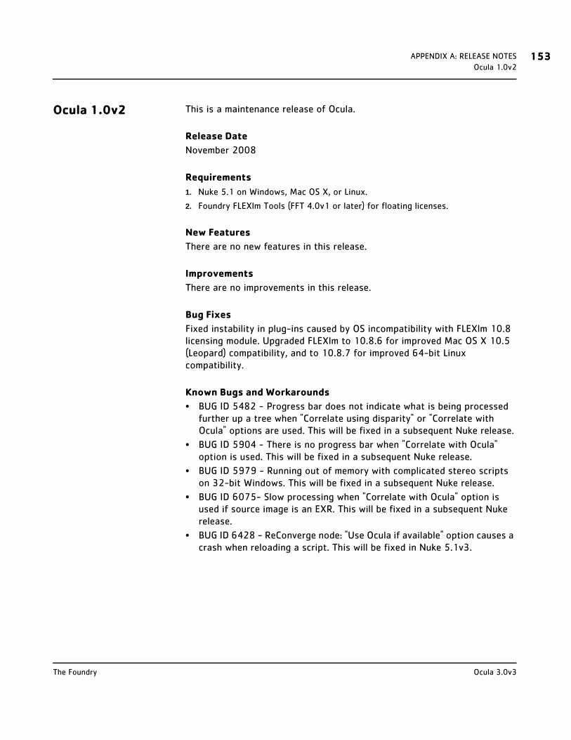
APPENDIX A: RELEASE NOTES 153Ocula 1.0v2
Ocula 1.0v2 This is a maintenance release of Ocula.
Release Date
November 2008
Requirements
1. Nuke 5.1 on Windows, Mac OS X, or Linux.
2. Foundry FLEXlm Tools (FFT 4.0v1 or later) for floating licenses.
New Features
There are no new features in this release.
Improvements
There are no improvements in this release.
Bug Fixes
Fixed instability in plug-ins caused by OS incompatibility with FLEXlm 10.8 licensing module. Upgraded FLEXlm to 10.8.6 for improved Mac OS X 10.5 (Leopard) compatibility, and to 10.8.7 for improved 64-bit Linux compatibility.
Known Bugs and Workarounds
• BUG ID 5482 - Progress bar does not indicate what is being processed further up a tree when "Correlate using disparity" or "Correlate with Ocula" options are used. This will be fixed in a subsequent Nuke release.
• BUG ID 5904 - There is no progress bar when "Correlate with Ocula" option is used. This will be fixed in a subsequent Nuke release.
• BUG ID 5979 - Running out of memory with complicated stereo scripts on 32-bit Windows. This will be fixed in a subsequent Nuke release.
• BUG ID 6075- Slow processing when "Correlate with Ocula" option is used if source image is an EXR. This will be fixed in a subsequent Nuke release.
• BUG ID 6428 - ReConverge node: "Use Ocula if available" option causes a crash when reloading a script. This will be fixed in Nuke 5.1v3.
Ocula 3.0v3The Foundry

APPENDIX A: RELEASE NOTES 154Ocula 1.0v1
Ocula 1.0v1 This is the first release of Ocula 1.0 for Nuke.
Release Date
October 2008
Requirements
1. Nuke 5.1 on Windows, Mac OS X, or Linux.
2. Foundry FLEXlm Tools (FFT 4.0v1 or later) for floating licenses.
New Features
In this release, there are five plug-ins and a collection of tools that add extra functionality to existing Nuke features.
Improvements
This section will describe improvements to existing features in later versions.
Bug Fixes
This section will describe fixed bugs in later versions.
Known Bugs and Workarounds
• BUG ID 5482 - Progress bar does not indicate what is being processed further up a tree when "Correlate using disparity" or "Correlate with Ocula" options are used. This will be fixed in a subsequent Nuke release.
• BUG ID 5904 - There is no progress bar when "Correlate with Ocula" option is used. This will be fixed in a subsequent Nuke release.
• BUG ID 5979 - Running out of memory with complicated stereo scripts on 32-bit Windows. This will be fixed in a subsequent Nuke release.
• BUG ID 6075- Slow processing when "Correlate with Ocula" option is used if source image is an EXR. This will be fixed in a subsequent Nuke release.
• BUG ID 6428 - ReConverge node: "Use Ocula if available" option causes a crash when reloading a script. This will be fixed in Nuke 5.1v3.
Ocula 3.0v3The Foundry
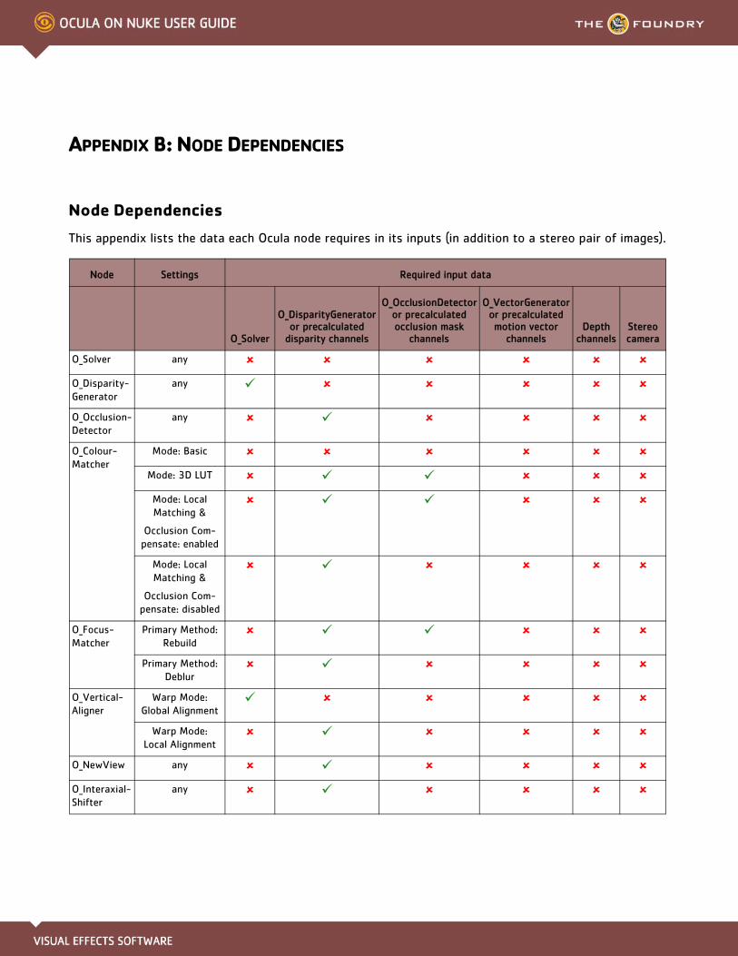
APPENDIX B: NODE DEPENDENCIES
Node Dependencies
This appendix lists the data each Ocula node requires in its inputs (in addition to a stereo pair of images).
Node Settings Required input data
O_Solver
O_DisparityGenerator or precalculated
disparity channels
O_OcclusionDetector or precalculated occlusion mask
channels
O_VectorGenerator or precalculated motion vector
channelsDepth
channelsStereo camera
O_Solver any
O_Disparity-Generator
any
O_Occlusion-Detector
any
O_Colour-Matcher
Mode: Basic
Mode: 3D LUT
Mode: Local Matching &
Occlusion Com-pensate: enabled
Mode: Local Matching &
Occlusion Com-pensate: disabled
O_Focus-Matcher
Primary Method: Rebuild
Primary Method: Deblur
O_Vertical-Aligner
Warp Mode: Global Alignment
Warp Mode: Local Alignment
O_NewView any
O_Interaxial-Shifter
any

APPENDIX B: NODE DEPENDENCIES 156Node Dependencies
O_Vector-Generator
any
O_Retimer any
O_Depth-ToDisparity
any
O_Disparity-ToDepth
any
O_Disparity-Viewer
any
Node Settings Required input data
O_Solver
O_DisparityGenerator or precalculated
disparity channels
O_OcclusionDetector or precalculated occlusion mask
channels
O_VectorGenerator or precalculated motion vector
channelsDepth
channelsStereo camera
Ocula 3.0v3The Foundry

APPENDIX C: THIRD PARTY LICENCES
Third Party Licences
This appendix lists third party libraries used in Ocula, along with their licences.
Library Description Licence
Boost Source code function / template library
Boost Software License - Version 1.0 - August 17th, 2003
Permission is hereby granted, free of charge, to any person or organization obtaining a copy of the software and accompanying documentation covered by this license (the “Software”) to use, reproduce, display, distribute, execute, and transmit the Software, and to prepare derivative works of the Software, and to permit third-parties to whom the Software is furnished to do so, all subject to the following:
The copyright notices in the Software and this entire statement, including the above license grant, this restriction and the following disclaimer, must be included in all copies of the Software, in whole or in part, and all derivative works of the Software, unless such copies or derivative works are solely in the form of machine-executable object code generated by a source language processor.
THE SOFTWARE IS PROVIDED “AS IS”, WITHOUT WARRANTY OF ANY KIND, EXPRESS OR IMPLIED, INCLUDING BUT NOT LIMITED TO THE WARRANTIES OF MERCHANT-ABILITY, FITNESS FOR A PARTICULAR PURPOSE, TITLE AND NON-INFRINGEMENT. IN NO EVENT SHALL THE COPYRIGHT HOLDERS OR ANYONE DISTRIBUTING THE SOFT-WARE BE LIABLE FOR ANY DAMAGES OR OTHER LIABILITY, WHETHER IN CONTRACT, TORT OR OTHERWISE, ARISING FROM, OUT OF OR IN CONNECTION WITH THE SOFT-WARE OR THE USE OR OTHER DEALINGS IN THE SOFTWARE.
Expat XML parser Copyright © 1998, 1999, 2000 Thai Open Source Software Center Ltd and Clark Cooper
Copyright © 2001, 2002, 2003, 2004, 2005, 2006 Expat maintainers.
Permission is hereby granted, free of charge, to any person obtaining a copy of this software and associated documentation files (the “Software”), to deal in the Software without restriction, including without limitation the rights to use, copy, modify, merge, publish, distribute, sublicense, and/or sell copies of the Software, and to per-mit persons to whom the Software is furnished to do so, subject to the following con-ditions:
The above copyright notice and this permission notice shall be included in all copies or substantial portions of the Software.
THE SOFTWARE IS PROVIDED “AS IS”, WITHOUT WARRANTY OF ANY KIND, EXPRESS OR IMPLIED, INCLUDING BUT NOT LIMITED TO THE WARRANTIES OF MERCHANT-ABILITY, FITNESS FOR A PARTICULAR PURPOSE AND NONINFRINGEMENT. IN NO EVENT SHALL THE AUTHORS OR COPYRIGHT HOLDERS BE LIABLE FOR ANY CLAIM, DAMAGES OR OTHER LIABILITY, WHETHER IN AN ACTION OF CONTRACT, TORT OR OTHERWISE, ARISING FROM, OUT OF OR IN CONNECTION WITH THE SOFTWARE OR THE USE OR OTHER DEALINGS IN THE SOFTWARE.

APPENDIX C: THIRD PARTY LICENCES 158Third Party Licences
FreeType Font support Portions of this software are copyright © 2008 The FreeType Project
(www.freetype.org). All rights reserved.
FTGL OpenGL support FTGL - OpenGL font library
Copyright © 2001-2004 Henry Maddocks [email protected]
Copyright © 2008 Sam Hocevar [email protected]
Copyright © 2008 Sean Morrison [email protected]
Permission is hereby granted, free of charge, to any person obtaining a copy of this software and associated documentation files (the “Software”), to deal in the Software without restriction, including without limitation the rights to use, copy, modify, merge, publish, distribute, sublicense, and/or sell copies of the Software, and to per-mit persons to whom the Software is furnished to do so, subject to the following con-ditions
The above copyright notice and this permission notice shall be included in all copies or substantial portions of the Software.
THE SOFTWARE IS PROVIDED “AS IS”, WITHOUT WARRANTY OF ANY KIND, EXPRESS OR IMPLIED, INCLUDING BUT NOT LIMITED TO THE WARRANTIES OF MERCHANT-ABILITY, FITNESS FOR A PARTICULAR PURPOSE AND NONINFRINGEMENT. IN NO EVENT SHALL THE AUTHORS OR COPYRIGHT HOLDERS BE LIABLE FOR ANY CLAIM, DAMAGES OR OTHER LIABILITY, WHETHER IN AN ACTION OF CONTRACT, TORT OR OTHERWISE, ARISING FROM, OUT OF OR IN CONNECTION WITH THE SOFTWARE OR THE USE OR OTHER DEALINGS IN THE SOFTWARE.
VXL Computer vision Copyright © 2000-2003 TargetJr Consortium
GE Corporate Research and Development (GE CRD)
1 Research Circle
Niskayuna, NY 12309
All Rights Reserved
Reproduction rights limited as described below.
Permission to use, copy, modify, distribute, and sell this software and its documenta-tion for any purpose is hereby granted without fee, provided that (i) the above copy-right notice and this permission notice appear in all copies of the software and related documentation, (ii) the name TargetJr Consortium (represented by GE CRD), may not be used in any advertising or publicity relating to the software without the specific, prior written permission of GE CRD, and (iii) any modifications are clearly marked and summarized in a change history log.
THE SOFTWARE IS PROVIDED “AS IS” AND WITHOUT WARRANTY OF ANY KIND, EXPRESS, IMPLIED OR OTHERWISE, INCLUDING WITHOUT LIMITATION, ANY WAR-RANTY OF MERCHANTABILITY OR FITNESS FOR A PARTICULAR PURPOSE. IN NO EVENT SHALL THE TARGETJR CONSORTIUM BE LIABLE FOR ANY SPECIAL, INCIDEN-TAL, INDIRECT OR CONSEQUENTIAL DAMAGES OF ANY KIND OR ANY DAMAGES WHATSOEVER RESULTING FROM LOSS OF USE, DATA OR PROFITS, WHETHER OR NOT ADVISED OF THE POSSIBILITY OF SUCH DAMAGES, OR ON ANY THEORY OF LIA-BILITY ARISING OUT OF OR IN CONNECTION WITH THE USE OR PERFORMANCE OF THIS SOFTWARE.
Library Description Licence
Ocula 3.0v3The Foundry
APPENDIX C: END USER LICENSE AGREEMENT
End User License Agreement (EULA)
IMPORTANT: BY INSTALLING THIS SOFTWARE YOU ACKNOWLEDGE THAT YOU HAVE READ THIS AGREEMENT, UNDERSTAND IT AND AGREE TO BE BOUND BY ITS TERMS AND CONDITIONS. IF YOU DO NOT AGREE TO THE TERMS OF THIS AGREEMENT DO NOT INSTALL, COPY OR USE THE SOFTWARE.
This END USER LICENSE AGREEMENT (this "Agreement") is made by and between The Foundry Visionmongers Ltd., a company registered in England and Wales, ("The Foundry"), and you, as either an individual or a single entity ("Licensee").
In consideration of the mutual covenants contained herein and for other good and valuable consideration (the receipt and sufficiency of which is acknowledged by each party hereto) the parties agree as follows:
SECTION 1. GRANT OF LICENSE.
Subject to the limitations of Section 2, The Foundry hereby grants to Licensee a limited, non-transferable and non-exclusive license to install and use a machine readable, object code version of this software program (the "Software") and accompanying user guide and other documentation (collectively, the "Documentation") solely for Licensee's own internal business purposes (collectively, the "License"); provided, however, Licensee's right to install and use the Software and the Documentation is limited to those rights expressly set out in this Agreement.
SECTION 2. RESTRICTIONS ON USE.
Licensee is authorized to use the Software in machine readable, object code form only, and Licensee shall not: (a) assign, sublicense, sell, distribute, transfer, pledge, lease, rent, share or export the Software, the Documentation or Licensee's rights hereunder; (b) alter or circumvent the copy protection mechanisms in the Software or reverse engineer, decompile, disassemble or otherwise attempt to discover the source code of the Software; (c) modify, adapt, translate or create derivative works based on the Software or Documentation; (d) use, or allow the use of, the Software or Documentation on any project other than a project produced by Licensee (an "Authorized Project"); (e) allow or permit anyone (other than Licensee and Licensee's authorized employees to the extent they are working on an Authorized Project) to use or have access to the Software or Documentation; (f) copy or install the Software or Documentation other than as expressly provided for herein; or (g) take any action, or fail to take action, that could adversely affect the trademarks, service marks, patents, trade secrets, copyrights or other intellectual property rights of The Foundry or any third party with intellectual property rights in the Software (each, a "Third Party Licensor"). Furthermore, for purposes of this Section 2, the term "Software" shall include any derivatives of the Software.
Licensee shall install and use only a single copy of the Software on one computer, unless the Software is installed in a "floating license" environment, in which case Licensee may install the Software on more than
APPENDIX C: END USER LICENSE AGREEMENT 160End User License Agreement (EULA)
one computer; provided, however, Licensee shall not at any one time use more copies of the Software than the total number of valid Software licenses purchased by Licensee.
Please note that in order to guard against unlicensed use of the Software a licence key is required to access and enable the Software. The issuing of replacement or substituted licence keys if the Software is moved from one computer to another is subject to and strictly in accordance with The Foundry’s Licence Transfer Policy, which is available on The Foundry’s website and which requires a fee to be paid in certain circumstances. The Foundry may from time to time and at its sole discretion vary the terms and conditions of the Licence Transfer Policy.
Furthermore, if the Software can be licensed on an "interactive" or "non-interactive" basis, licensee shall be authorized to use a non-interactive version of the Software for rendering purposes only (i.e., on a CPU, without a user, in a non-interactive capacity) and shall not use such Software on workstations or otherwise in a user-interactive capacity. Licensee shall be authorized to use an interactive version of the Software for both interactive and non-interactive rendering purposes, if available.
If Licensee has purchased the Software on the discount terms offered by The Foundry’s Educational Policy published on its website (“the Educational Policy”), Licensee warrants and represents to The Foundry as a condition of this Agreement that: (a) (if Licensee is an individual) he or she is a part-time or full-time student at the time of purchase and will not use the Software for commercial, professional or for-profit purposes; (b) (if the Licensee is not an individual) it is an organisation that will use it only for the purpose of training and instruction, and for no other purpose (c) Licensee will at all times comply with the Educational Policy (as such policy may be amended from time to time).
Finally, if the Software is a "Personal Learning Edition," (“PLE”) Licensee may use it only for the purpose of personal or internal training and instruction, and for no other purpose. PLE versions of the Software may not be used for commercial, professional or for-profit purposes including, for the avoidance of doubt, the purpose of providing training or instruction to third parties.
SECTION 3. SOURCE CODE.
Notwithstanding that Section 1 defines “Software” as an object code version and that Section 2 provides that Licensee may use the Software in object code form only, The Foundry may also agree to license to Licensee (including by way of upgrades, updates or enhancements) source code or elements of the source code of the Software the intellectual property rights in which belong either to The Foundry or to a Third Party Licensor (“Source Code”). If The Foundry does so Licensee shall be licensed to use the Source Code as Software on the terms of this Agreement and: (a) notwithstanding Section 2 (c) Licensee may use the Source Code at its own risk in any reasonable way for the limited purpose of enhancing its use of the Software solely for its own internal business purposes and in all respects in accordance with this Agreement; (b) Licensee shall in respect of the Source Code comply strictly with all other restrictions applying to its use of the Software under this Agreement as well as any other restriction or instruction that is communicated to it by The Foundry at any time during this Agreement (whether imposed or requested by The Foundry or by any Third Party Licensor); (c) notwithstanding any other term of this Agreement The Foundry gives no warranty whatsoever in respect of the Source Code, which is licensed on an “as is” basis, or in respect of any modification of the Source Code made by Licensee (“Modification”); (d)
Ocula 3.0v3The Foundry

APPENDIX C: END USER LICENSE AGREEMENT 161End User License Agreement (EULA)
notwithstanding any other term of this Agreement The Foundry shall have no obligation to provide support, maintenance, upgrades or updates of or in respect of the Source Code or of any Modification; and (e) Licensee shall indemnify The Foundry against all liabilities and expenses (including reasonable legal costs) incurred by The Foundry in relation to any claim asserting that any Modification infringes the intellectual property rights of any third party.
SECTION 4. BACK-UP COPY.
Notwithstanding Section 2, Licensee may store one copy of the Software and Documentation off-line and off-site in a secured location owned or leased by Licensee in order to provide a back-up in the event of destruction by fire, flood, acts of war, acts of nature, vandalism or other incident. In no event may Licensee use the back-up copy of the Software or Documentation to circumvent the usage or other limitations set forth in this Agreement.
SECTION 5. OWNERSHIP.
Licensee acknowledges that the Software (including, for the avoidance of doubt, any Source Code that is licensed to Licensee) and Documentation and all intellectual property rights and other proprietary rights relating thereto are and shall remain the sole property of The Foundry and the Third Party Licensors. Licensee shall not remove, or allow the removal of, any copyright or other proprietary rights notice included in and on the Software or Documentation or take any other action that could adversely affect the property rights of The Foundry or any Third Party Licensor. To the extent that Licensee is authorized to make copies of the Software or Documentation under this Agreement, Licensee shall reproduce in and on all such copies any copyright and/or other proprietary rights notices provided in and on the materials supplied by The Foundry hereunder. Nothing in this Agreement shall be deemed to give Licensee any rights in the trademarks, service marks, patents, trade secrets, confidential information, copyrights or other intellectual property rights of The Foundry or any Third Party Licensor, and Licensee shall be strictly prohibited from using the name, trademarks or service marks of The Foundry or any Third Party Licensor in Licensee's promotion or publicity without The Foundry's express written approval.
SECTION 6. LICENSE FEE.
Licensee understands that the benefits granted to Licensee hereunder are contingent upon Licensee's payment in full of the license fee payable in connection herewith (the "License Fee").
SECTION 7. UPGRADES/ENHANCEMENTS.
The Licensee's access to support, upgrades and updates is subject to the terms and conditions of the "Annual Upgrade and Support Programme” available on The Foundry's website. The Foundry may from time to time and at its sole discretion vary the terms and conditions of the Annual Upgrade and Support Programme.
SECTION 8. TAXES AND DUTIES.
Licensee agrees to pay, and indemnify The Foundry from claims for, any local, state or national tax (exclusive of taxes based on net income), duty, tariff or other impost related to or arising from the transaction contemplated by this Agreement.
Ocula 3.0v3The Foundry

APPENDIX C: END USER LICENSE AGREEMENT 162End User License Agreement (EULA)
SECTION 9. LIMITED WARRANTY.
The Foundry warrants that, for a period of ninety (90) days after delivery of the Software: (a) the machine readable electronic files constituting the Software and Documentation shall be free from errors that may arise from the electronic file transfer from The Foundry and/or its authorized reseller to Licensee; and (b) to the best of The Foundry's knowledge, Licensee's use of the Software in accordance with the Documentation will not, in and of itself, infringe any third party's copyright, patent or other intellectual property rights. Except as warranted, the Software and Documentation is being provided "as is." THE FOREGOING LIMITED WARRANTY IS IN LIEU OF ALL OTHER WARRANTIES OR CONDITIONS, EXPRESS OR IMPLIED, AND The Foundry DISCLAIMS ANY AND ALL IMPLIED WARRANTIES OR CONDITIONS, INCLUDING, WITHOUT LIMITATION, ANY IMPLIED WARRANTY OF TITLE, NON-INFRINGEMENT, MERCHANTABILITY OR FITNESS FOR A PARTICULAR PURPOSE, REGARDLESS OF WHETHER The Foundry KNOWS OR HAS REASON TO KNOW OF LICENSEE'S PARTICULAR NEEDS. The Foundry does not warrant that the Software or Documentation will meet Licensee's requirements or that Licensee's use of the Software will be uninterrupted or error free. No employee or agent of The Foundry is authorized to modify this limited warranty, nor to make additional warranties. No action for any breach of the above limited warranty may be commenced more than one (1) year after Licensee's initial receipt of the Software. To the extent any implied warranties may not be disclaimed under applicable law, then ANY IMPLIED WARRANTIES ARE LIMITED IN DURATION TO NINETY (90) DAYS AFTER DELIVERY OF THE SOFTWARE TO LICENSEE.
SECTION 10. LIMITED REMEDY.
The exclusive remedy available to the Licensee in the event of a breach of the foregoing limited warranty, TO THE EXCLUSION OF ALL OTHER REMEDIES, is for Licensee to destroy all copies of the Software, send The Foundry a written certification of such destruction and, upon The Foundry's receipt of such certification, The Foundry will make a replacement copy of the Software available to Licensee.
SECTION 11. INDEMNIFICATION.
Licensee agrees to indemnify, hold harmless and defend The Foundry, the Third Party Licensors and The Foundry's and each Third Party Licensor’s respective affiliates, officers, directors, shareholders, employees, authorized resellers, agents and other representatives (collectively, the "Released Parties") from all claims, defense costs (including, but not limited to, attorneys' fees), judgments, settlements and other expenses arising from or connected with the operation of Licensee's business or Licensee's possession or use of the Software or Documentation.
SECTION 12. LIMITED LIABILITY.
In no event shall the Released Parties' cumulative liability to Licensee or any other party for any loss or damages resulting from any claims, demands or actions arising out of or relating to this Agreement (or the Software or Documentation contemplated herein) exceed the License Fee paid to The Foundry or its authorized reseller for use of the Software. Furthermore, IN NO EVENT SHALL THE RELEASED PARTIES BE LIABLE TO LICENSEE UNDER ANY THEORY FOR ANY INDIRECT, SPECIAL, INCIDENTAL, PUNITIVE, EXEMPLARY OR CONSEQUENTIAL DAMAGES (INCLUDING DAMAGES FOR LOSS OF BUSINESS OR LOSS OF PROFITS) OR THE COST OF PROCUREMENT OF SUBSTITUTE GOODS OR SERVICES, REGARDLESS OF WHETHER THE RELEASED PARTIES KNOW OR HAVE REASON TO KNOW OF THE POSSIBILITY OF SUCH DAMAGES AND REGARDLESS OF WHETHER ANY REMEDY SET FORTH HEREIN FAILS OF ITS ESSENTIAL
Ocula 3.0v3The Foundry

APPENDIX C: END USER LICENSE AGREEMENT 163End User License Agreement (EULA)
PURPOSE. No action arising out of or related to this Agreement, regardless of form, may be brought by Licensee more than one (1) year after Licensee's initial receipt of the Software; provided, however, to the extent such one (1) year limit may not be valid under applicable law, then such period shall be limited to the shortest period allowed by law.
SECTION 13. TERM; TERMINATION.
This Agreement is effective upon Licensee's acceptance of the terms hereof and Licensee's payment of the License Fee, and the Agreement will remain in effect until termination. If Licensee breaches this Agreement, The Foundry may terminate the License granted hereunder by notice to Licensee. In the event the License is terminated, Licensee will either return to The Foundry all copies of the Software and Documentation in Licensee's possession or, if The Foundry directs in writing, destroy all such copies. In the later case, if requested by The Foundry, Licensee shall provide The Foundry with a certificate signed by an officer of Licensee confirming that the foregoing destruction has been completed.
SECTION 14. CONFIDENTIALITY.
Licensee agrees that the Software (including, for the avoidance of doubt, any Source Code that is licensed to Licensee) and Documentation are proprietary and confidential information of The Foundry or, as the case may be, the Third Party Licensors, and that all such information and any communications relating thereto (collectively, "Confidential Information") are confidential and a fundamental and important trade secret of The Foundry or the Third Party Licensors. Licensee shall disclose Confidential Information only to Licensee's employees who are working on an Authorized Project and have a "need-to-know" of such Confidential Information, and shall advise any recipients of Confidential Information that it is to be used only as authorized in this Agreement. Licensee shall not disclose Confidential Information or otherwise make any Confidential Information available to any other of the Licensee's employees or to any third parties without the express written consent of The Foundry. Licensee agrees to segregate, to the extent it can be reasonably done, the Confidential Information from the confidential information and materials of others in order to prevent commingling. Licensee shall take reasonable security measures, which such measures shall be at least as great as the measures Licensee uses to keep Licensee's own confidential information secure (but in any case using no less than a reasonable degree of care), to hold the Software, Documentation and any other Confidential Information in strict confidence and safe custody. The Foundry may request, in which case Licensee agrees to comply with, certain reasonable security measures as part of the use of the Software and Documentation. Licensee acknowledges that monetary damages may not be a sufficient remedy for unauthorized disclosure of Confidential Information, and that The Foundry shall be entitled, without waiving any other rights or remedies, to such injunctive or equitable relief as may be deemed proper by a court of competent jurisdiction.
SECTION 15. INSPECTION.
Licensee shall advise The Foundry on demand of all locations where the Software or Documentation is used or stored. Licensee shall permit The Foundry or its authorized agents to inspect all such locations during normal business hours and on reasonable advance notice.
Ocula 3.0v3The Foundry

APPENDIX C: END USER LICENSE AGREEMENT 164End User License Agreement (EULA)
SECTION 16. NONSOLICITATION.
Licensee agrees not to solicit for employment or retention any of The Foundry's current or future employees who were or are involved in the development and/or creation of the Software.
SECTION 17. U.S. GOVERNMENT LICENSE RIGHTS.
The Software, Documentation and/or data delivered hereunder are subject to the terms of this Agreement and in no event shall the U.S. Government acquire greater than RESTRICTED/LIMITED RIGHTS. At a minimum, use, duplication or disclosure by the U.S. Government is subject to the applicable restrictions of: (i) FAR §52.227-14 ALTS I, II and III (June 1987); (ii) FAR §52.227-19 (June 1987); (iii) FAR §12.211 and 12.212; and/or (iv) DFARS §227.7202-1(a) and DFARS §227.7202-3.
The Software is the subject of the following notices:
• Copyright © 2012 The Foundry Visionmongers, Ltd.. All Rights Reserved.
• Unpublished-rights reserved under the Copyright Laws of the United Kingdom.
SECTION 18. SURVIVAL.
Sections 2, 3, 5, 6, 8, 9, 10, 11, 12, 13, 14, 15, 16, 17, 18, 19 and 20 shall survive any termination or expiration of this Agreement.
SECTION 19. IMPORT/EXPORT CONTROLS.
To the extent that any Software made available hereunder is subject to restrictions upon export and/or reexport from the United States, Licensee agrees to comply with, and not act or fail to act in any way that would violate, the applicable international, national, state, regional and local laws and regulations, including, without limitation, the United States Foreign Corrupt Practices Act, the Export Administration Act and the Export Administration Regulations, as amended or otherwise modified from time to time, and neither The Foundry nor Licensee shall be required under this Agreement to act or fail to act in any way which it believes in good faith will violate any such laws or regulations.
SECTION 20. MISCELLANEOUS.
This Agreement is the exclusive agreement between the parties concerning the subject matter hereof and supersedes any and all prior oral or written agreements, negotiations, or other dealings between the parties concerning such subject. This Agreement may be modified only by a written instrument signed by both parties. If any action is brought by either party to this Agreement against the other party regarding the subject matter hereof, the prevailing party shall be entitled to recover, in addition to any other relief granted, reasonable attorneys' fees and expenses of litigation. Should any term of this Agreement be declared void or unenforceable by any court of competent jurisdiction, such declaration shall have no effect on the remaining terms of this Agreement. The failure of either party to enforce any rights granted hereunder or to take action against the other party in the event of any breach hereunder shall not be deemed a waiver by that party as to subsequent enforcement of rights or subsequent actions in the event of future breaches. This Agreement shall be governed by, and construed in accordance with English Law.
The Foundry and Licensee intend that each Third Party Licensor may enforce against Licensee under the
Ocula 3.0v3The Foundry

APPENDIX C: END USER LICENSE AGREEMENT 165End User License Agreement (EULA)
Contracts (Rights of Third Parties) Act 1999 ("the Act") any obligation owed by Licensee to The Foundry under this Agreement that is capable of application to any proprietary or other right of that Third Party Licensor in or in relation to the Software. The Foundry and Licensee reserve the right under section 2(3)(a) of the Act to rescind, terminate or vary this Agreement without the consent of any Third Party Licensor.
Copyright © 2012 The Foundry Visionmongers Ltd. All Rights Reserved. Do not duplicate.
Ocula 3.0v3The Foundry
INDEX
A-Z
Aalignment
horizontal 95vertical 77
Bbackward motion vector fields 99
Ccameras
converging 77parallel 77
colour discrepancies 54colours
matching between views 54, 86converging cameras 77correcting
colour differences 54focus differences 65horizontal alignment 95vertical alignment 77
creatinga new view 87disparity fields 32motion vector fields 99occlusion masks 47two new views 95
Ddisparity channel 32disparity fields 32, 124disparity vectors 32, 99, 124
Eend user licensing agreement 159EULA 159
Ffocus
matching between views 65forward motion vector fields 99Foundry, The 16
Hhorizontal alignment
correcting 95Host ID number 11
Iinstallation 6
on Linux 9on Mac 8on Windows 7
interaxial distance 95
Kkeystoning 77
LLicensing Ocula 10lmhostid number 11
Mmotion vector fields 26, 99
backward 99forward 99
OO_ColourMatcher 54, 86O_DepthToDisparity 32, 113O_DisparityGenerator 32O_DisparityToDepth 117, 118O_DisparityViewer 124O_FocusMatcher 65O_InteraxialShifter 46, 95O_NewView 87O_OcclusionDetector 47O_Retimer 106O_Solver 18, 87, 118O_VectorGenerator 99O_VerticalAligner 77occlusion masks 47occlusions 87, 96
detecting 47
Pparallel cameras 77
Rrelease notes 134
retiming stereo footage 106
Sslowing down stereo footage 106speeding up stereo footage 106
TThe Foundry 16The Foundry products 16third party licences 157
Vvertical alignment
correcting 77views
creating new 87