NU TRIO 250 350 ind045 - dedietrich-heating.com Labels and rating plates must be legible throughout...
24
TRIO DT 250 - TRIO DT 350 Solar domestic hot water tanks DIETRISOL User Guide 300028005-001-05 en
Transcript of NU TRIO 250 350 ind045 - dedietrich-heating.com Labels and rating plates must be legible throughout...

TRIO DT 250 - TRIO DT 350Solar domestic hot water tanks
DIETRISOL
User Guide
300028005-001-05
en

Contents
1 Safety instructions . . . . . . . . . . . . . . . . . . . . . . . . . . . . . . . . . . . . . . . . . . . . . . . . . . . . . . . . . . . . . . . . . . . . . . .31.1 General safety instructions . . . . . . . . . . . . . . . . . . . . . . . . . . . . . . . . . . . . . . . . . . . . . . . . . . . . . . . . . . . . . . . . . . . . . . . . . . . . . . . . .31.2 Recommendations . . . . . . . . . . . . . . . . . . . . . . . . . . . . . . . . . . . . . . . . . . . . . . . . . . . . . . . . . . . . . . . . . . . . . . . . . . . . . . . . . . . . . . .41.3 Liabilities . . . . . . . . . . . . . . . . . . . . . . . . . . . . . . . . . . . . . . . . . . . . . . . . . . . . . . . . . . . . . . . . . . . . . . . . . . . . . . . . . . . . . . . . . . . . . . .4
1.3.1 Manufacturer's liability . . . . . . . . . . . . . . . . . . . . . . . . . . . . . . . . . . . . . . . . . . . . . . . . . . . . . . . . . . . . . . . . . . . . . . . . . . . . . .41.3.2 Installer's liability . . . . . . . . . . . . . . . . . . . . . . . . . . . . . . . . . . . . . . . . . . . . . . . . . . . . . . . . . . . . . . . . . . . . . . . . . . . . . . . . . .4
2 About this manual . . . . . . . . . . . . . . . . . . . . . . . . . . . . . . . . . . . . . . . . . . . . . . . . . . . . . . . . . . . . . . . . . . . . . . . .52.1 Symbols used . . . . . . . . . . . . . . . . . . . . . . . . . . . . . . . . . . . . . . . . . . . . . . . . . . . . . . . . . . . . . . . . . . . . . . . . . . . . . . . . . . . . . . . . . . .5
2.1.1 Symbols used in the manual . . . . . . . . . . . . . . . . . . . . . . . . . . . . . . . . . . . . . . . . . . . . . . . . . . . . . . . . . . . . . . . . . . . . . . . . .5
3 Technical specifications . . . . . . . . . . . . . . . . . . . . . . . . . . . . . . . . . . . . . . . . . . . . . . . . . . . . . . . . . . . . . . . . . . .63.1 Homologations . . . . . . . . . . . . . . . . . . . . . . . . . . . . . . . . . . . . . . . . . . . . . . . . . . . . . . . . . . . . . . . . . . . . . . . . . . . . . . . . . . . . . . . . . .63.1.1 Certifications. . . . . . . . . . . . . . . . . . . . . . . . . . . . . . . . . . . . . . . . . . . . . . . . . . . . . . . . . . . . . . . . . . . . . . . . . . . . . . . . . . . . . . . . . . . .63.1.2 Directives . . . . . . . . . . . . . . . . . . . . . . . . . . . . . . . . . . . . . . . . . . . . . . . . . . . . . . . . . . . . . . . . . . . . . . . . . . . . . . . . . . . . . . . . . . . . . .63.2 Technical data . . . . . . . . . . . . . . . . . . . . . . . . . . . . . . . . . . . . . . . . . . . . . . . . . . . . . . . . . . . . . . . . . . . . . . . . . . . . . . . . . . . . . . . . . .73.3 Main parts . . . . . . . . . . . . . . . . . . . . . . . . . . . . . . . . . . . . . . . . . . . . . . . . . . . . . . . . . . . . . . . . . . . . . . . . . . . . . . . . . . . . . . . . . . . . . .8
4 Setting the DHW calorifier outlet temperature . . . . . . . . . . . . . . . . . . . . . . . . . . . . . . . . . . . . . . . . . . . . . . . . .94.1 Programming and setting the electrical back-up. . . . . . . . . . . . . . . . . . . . . . . . . . . . . . . . . . . . . . . . . . . . . . . . . . . . . . . . . . . . . . . . .94.2 Setting the thermostatic mixing valve . . . . . . . . . . . . . . . . . . . . . . . . . . . . . . . . . . . . . . . . . . . . . . . . . . . . . . . . . . . . . . . . . . . . . . . . .9
5 solar regulator . . . . . . . . . . . . . . . . . . . . . . . . . . . . . . . . . . . . . . . . . . . . . . . . . . . . . . . . . . . . . . . . . . . . . . . . . .105.1 General description of how the unit operates . . . . . . . . . . . . . . . . . . . . . . . . . . . . . . . . . . . . . . . . . . . . . . . . . . . . . . . . . . . . . . . . . .105.2 Start-up. . . . . . . . . . . . . . . . . . . . . . . . . . . . . . . . . . . . . . . . . . . . . . . . . . . . . . . . . . . . . . . . . . . . . . . . . . . . . . . . . . . . . . . . . . . . . . .105.3 Adjustment keys . . . . . . . . . . . . . . . . . . . . . . . . . . . . . . . . . . . . . . . . . . . . . . . . . . . . . . . . . . . . . . . . . . . . . . . . . . . . . . . . . . . . . . . .115.4 Measured values and adjustment parameters . . . . . . . . . . . . . . . . . . . . . . . . . . . . . . . . . . . . . . . . . . . . . . . . . . . . . . . . . . . . . . . . .125.4 Measured values and adjustment parameters . . . . . . . . . . . . . . . . . . . . . . . . . . . . . . . . . . . . . . . . . . . . . . . . . . . . . . . . . . . . . . . . .12
6 Checking and maintenance . . . . . . . . . . . . . . . . . . . . . . . . . . . . . . . . . . . . . . . . . . . . . . . . . . . . . . . . . . . . . . .176.1 Solar installation . . . . . . . . . . . . . . . . . . . . . . . . . . . . . . . . . . . . . . . . . . . . . . . . . . . . . . . . . . . . . . . . . . . . . . . . . . . . . . . . . . . . . . . .176.2 Tank . . . . . . . . . . . . . . . . . . . . . . . . . . . . . . . . . . . . . . . . . . . . . . . . . . . . . . . . . . . . . . . . . . . . . . . . . . . . . . . . . . . . . . . . . . . . . . . . .17
6.2.1 Magnesium anodes . . . . . . . . . . . . . . . . . . . . . . . . . . . . . . . . . . . . . . . . . . . . . . . . . . . . . . . . . . . . . . . . . . . . . . . . . . . . . . .176.2.2 Safety valve or safety unit . . . . . . . . . . . . . . . . . . . . . . . . . . . . . . . . . . . . . . . . . . . . . . . . . . . . . . . . . . . . . . . . . . . . . . . . . .176.2.3 Descaling . . . . . . . . . . . . . . . . . . . . . . . . . . . . . . . . . . . . . . . . . . . . . . . . . . . . . . . . . . . . . . . . . . . . . . . . . . . . . . . . . . . . . . .176.2.4 Casing . . . . . . . . . . . . . . . . . . . . . . . . . . . . . . . . . . . . . . . . . . . . . . . . . . . . . . . . . . . . . . . . . . . . . . . . . . . . . . . . . . . . . . . . .176.2.5 Vent device . . . . . . . . . . . . . . . . . . . . . . . . . . . . . . . . . . . . . . . . . . . . . . . . . . . . . . . . . . . . . . . . . . . . . . . . . . . . . . . . . . . . .17
6.3 Solar circuit . . . . . . . . . . . . . . . . . . . . . . . . . . . . . . . . . . . . . . . . . . . . . . . . . . . . . . . . . . . . . . . . . . . . . . . . . . . . . . . . . . . . . . . . . . . .17
Warranty certificate . . . . . . . . . . . . . . . . . . . . . . . . . . . . . . . . . . . . . . . . . . . . . . . . . . . . . . . . . . . . . . . . . . . . . .19
7 Appendix - Information on the Ecodesign and Energy Labelling Directives. . . . . . . . . . . . . . . . . . . . . . . .20
2 TRIO DT 250 - TRIO DT 350 16/07/2015 - 300028005-001-05

1 Safety instructions1.1 General safety instructions
DangerThis appliance can be used by children agedfrom 8 years and above and persons withreduced physical, sensory or mental capabilitiesor lack of experience and knowledge if they havebeen given supervision or instructionconcerning use of the appliance in a safe wayand understand the hazards involved. Childrenshall not play with the appliance. Cleaning anduser maintenance shall not be made by childrenwithout supervision. Allowance must be made for a means ofdisconnection in the fixed pipes in accordancewith the regulations on installations.If a power cord is provided with the applianceand it turns out to be damaged, it must bereplaced by the manufacturer, its after salesservice or persons with similar qualifications inorder to obviate any danger.Draining the appliance:
Turn off the domestic cold water inletOpen a hot water tap on the installationOpen a safety unit valveWhen the water stops flowing, the appliance has
been drained
Respect the maximum water inlet pressure toensure correct operation of the appliance,referring to the chapter "TechnicalSpecifications".Any operation on the installation must beperformed by a qualified technician respectingprofessional regulations and in accordance withthis document.Before any work, switch off the mains supply tothe appliance. Protect the installation againstany unwanted restarts.Solar installations must be earthed to protectthem against lightning.Operation of the thermostatic mixing valve onthe solar hot water tank outlet must be checkedon commissioning of the solar system.Pressure limiter device:
The pressure limiter device (safety valve or safetyunit) must be operated regularly in order to clear outany limescale deposits and ensure that it is notblocked
The pressure limiter device must be connected toa discharge pipe
As water may flow from the discharge pipe, it mustbe kept open to the air, in a frost-free environment,in a continuous downward gradient
316/07/2015 - 300028005-001-05 TRIO DT 250 - TRIO DT 350

1.2 Recommendations
.Heating water and domestic water must notcome into contact with each other. Thecirculation of drinking water must not be done inthe exchanger but only in the tank.Insulate the pipes to reduce heat losses to aminimum.
Only remove the casing for maintenance and repairoperations. Put the casing back in place aftermaintenance and repair operations.
We recommend installing an EC175 package on the collector sensor.The installation must comply in all matters to the standards and rules which govern the work and interventions in individual and collective homes, and other constructions.France: DTU 65.12, NF P50-601, NF 12976-2.
Service the appliance regularly to ensure that it operates correctly. Contact a qualified professional or take out a maintenance contract for the annual servicing of the appliance.As the heat transporting fluid leaks much more easily than water, carry out a visual check on the tightness of all fittings and gaskets after a few hours' operation at normal operating pressure.To take advantage of the guarantee, no modifications must be made to the appliance. The choice of components for the solar system and their installation must follow the instructions in this manual.
Never remove or cover labels and rating platesaffixed to the appliance. Labels and rating platesmust be legible throughout the entire lifetime of theappliance. Immediately replace damaged or illegibleinstruction or safety labels.
1.3 Liabilities
1.3.1 Manufacturer's liability
Our products are manufactured in compliance with the requirements of the various applicable European Directives. They are therefore delivered with marking and all relevant documentation.In the interest of customers, we are continuously endeavouring to make improvements in product quality. All the specifications stated in this document are therefore subject to change without notice.
Our liability as the manufacturer may not be invoked in the following cases:
Failure to abide by the instructions on installing theappliance
Failure to abide by the instructions on using theappliance
Faulty or insufficient maintenance of the appliance
1.3.2 Installer's liability
The installer is responsible for the installation and commissioning of the appliance. The installer is required to observe the following instructions:
Read and follow the instructions given in themanuals provided with the appliance
Install the appliance in acordance with the legislationand standards currently in force
Perform the initial start up and carry out any checksnecessary
Explain the installation to the user
If a maintenance is necessary, warn the user of theobligation to check the appliance and maintain it ingood working order
Give all the instruction manuals to the user
4 TRIO DT 250 - TRIO DT 350 16/07/2015 - 300028005-001-05

2 About this manual
2.1 Symbols used
2.1.1 Symbols used in the manual
In these instructions, various markings and pictograms are used todraw your attention to particular information. In so doing, De DietrichThermique S.A.S wishes to safeguard the user's safety, obviatehazards and guarantee correct operation of the appliance.
DangerRisk of a dangerous situation causing serious physicalinjury.
WarningRisk of a dangerous situation causing slight physicalinjury.
CautionRisk of material damage.
Specific information.
ReferenceRefer to another manual or other pages in this instructionmanual.
DHW: Domestic hot water.
516/07/2015 - 300028005-001-05 TRIO DT 250 - TRIO DT 350

3 Technical specifications
3.1 Homologations
3.1.1 Certifications
NF certification
3.1.2 Directives
Compliance of design and manufactureThis product conforms to the requirements of european directive 97 /23 / EC, article 3, paragraph 3, on pressure equipment.
Electrical compliance / Marking This product complies to the requirements to the european directivesand following standards:• 2006/95/EC Low Voltage Directive
Reference Standard: EN 60.335.1Reference Standard: EN 60.335.2.21.
2004/108/EC Electromagnetic Compatibility DirectiveReference Standards: EN 50.081.1 / EN 50.082.1 / EN 55.014.
6 TRIO DT 250 - TRIO DT 350 16/07/2015 - 300028005-001-05

3.2 Technical data
DIETRISOL TRIO DT 250
DIETRISOL TRIO DT 350
Maximum operating temperatureSolar exchangers °C 110 110Boiler heat exchanger °C 110 110tank °C 90 90
Maximum operating pressure Mpa (bar) 0.7 (7) 1 (10)
Maximum operating pressure in accordance with W/TPW (1) Mpa (bar) 0.6 (6) 0.6 (6)
Water contentSolar exchangers litres 8 7.2Boiler heat exchanger litres 4.3 4.9tank litres 247 350
Surface area
Upper solar heat exchanger m2 0.48 0.48
Lower solar heat exchanger m2 0.86 0.96
Boiler heat exchanger m2 0.64 0.72
Operation with boiler back-upTop up volume litres 105 127Solar volume litres 142 223Power exchanged (2) (3) kW 21 23
Operation with electrical back-up
Top up volume litres 130 160Solar volume litres 117 190Output of the electrical back-up kW 2.4 3Back-up volume heating time (from 15 to 60°C) h 2h50 2h50
Vecs 40 (5) (6)Domestic hot water storage temperature: 55 °C
litres 355 420
Vecs40 (5) (6)Domestic hot water storage temperature: 60 °C
litres 385 450
Continuous output ∆T = 35 K (2) (3) l/h 515 565
Flow rate for 10 minutes where ∆T = 30 K (on make-up volume) (2) (4)
l/10 mm 190 230
Maintenance consumption kWh/24h 2.20 2.7Cooling constant Cr Wh/lKj 0.22 0.19(1) Swiss Directives(2) Domestic cold water input at 10°C - Primary inlet temperature at 80 °C
Values measured with a wall-mounted boiler(3) Domestic hot water temperature: 45 °C(4) Domestic hot water temperature: 40 °C(5) Domestic cold water inlet 15 °C(6) Values measured only on the back-up volume
Domestic hot water load setting: 60 °C
716/07/2015 - 300028005-001-05 TRIO DT 250 - TRIO DT 350

3.3 Main parts
Dietrisol TRIO DT is a high performance solar DHW tank/calorifierdesigned to be connected to Dietrisol NEO or POWER solarcollectors and an De Dietrich central heating boiler.It is designed in such a way as to be able to cope with a solar collectorsurface area of up to 4.5 m2 (DT 250) and 6.5 m2 (DT 350) under theconditions set out in the chapter "Hydraulic Connection Primary SolarCircuit".
tankThe high quality steel tank is lined with food standard quality vitrified enamel, which protects it from corrosion and preserves all the qualities of the domestic water.The Dietrisol TRIO DT tank is fitted with 2 heat exchangers per zone for solar heating and one heat exchanger for supplementary heating by means of a fuel oil or gas boiler.
Protection against corrosionThe tank is also protected from corrosion by two magnesium anodes which must be inspected every 2 years and replaced if necessary.
Heat exchangerThe thermal exchanger welded into the tank is made of smooth piping, the inside of which, which is in contact with the domestic water, is enamelled.
InsulationThe tank is strongly insulated with high strength rigid polyurethane foam with no chlorofluorocarbons (CFC), 50 mm thick to minimise heat loss.
CasingThe outside casing is made of painted steel sheeting.The top and side covers are made of ABS.
Solar stationThe solar heating pump unit comprises the solar circuit safety unit, a pressure and temperature gauge and a flowmeter to visualise circulation of the solar fluid between the collectors and the DHW tank. An expansion vessel is connected to the solar unit; it is used to compensate for the expansion of the solar fluid in which the temperature varies between 0 and 150°C.
Sol Plus TRIO regulatorThe control system is the solar system's brain; it makes the solar heating pump run at variable speeds according to the difference in temperature between the bottom of the DHW tank and the solar collectors. The control system manages the set point temperature (temperature to be attained in the DHW tank), overheating and nighttime cooling. The control system also displays the various operating modes, the temperatures in the collectors and in the bottom of the DHW tank, as well as signalling any malfunctions.
1 Pressure gauge - Primary solar circuit2 Safety control unit for the solar circuit (6 bar)3 Blue thermometer (tank solar heat exchangers outlet)4 Red thermometer (tank solar heat exchangers inlet)5 Primary solar circuit pump6 Manual bleed degasser7 2-position 3-way directional valve8 Sol Plus TRIO regulator9 8 l/6 bar expansion vessel, 2-bar pre-load10 Automatic connection for expansion vessel11 Primary solar circuit filling and draining device12 Magnesium anode13 Electric heating resistance14 Magnesium anode
8 TRIO DT 250 - TRIO DT 350 16/07/2015 - 300028005-001-05

4 Setting the DHW calorifier outlet temperature
4.1 Programming and setting the electrical back-up
The temperature of the volume of water heated by the electricalresistor is set by the installer on commissioning of the installationaccording to the size of the home.Using the programming device installed in the electrical panel, it ispossible to adjust the volume of water heated to 40°C by the resistorin two ways:
By forcing contunuous heating by the resistor (off-peak hourscontact) for significant unforeseen needs.
By programming the heating time outside off-peak periods (2hours maximum according to the DHW volume at 40°Crequired) to compensate for the lack of sunshine in winter, forexample. The programmed period outside off-peak hours mustpreferably be between 12 h and 18 h.
4.2 Setting the thermostatic mixing valve
28. Domestic cold water inlet57. DHW tank domestic hot water outlet
The mixing valve is set in the factory for a DHW outlet temperature of50°C (position 4). To lower this temperature, remove the top coverand turn the wheel anti-clockwise. In position 1, the outlettemperature is lowered to 35°C.
C003732-B
57
28
916/07/2015 - 300028005-001-05 TRIO DT 250 - TRIO DT 350

5 solar regulator
Always fitted to installation type 1 (Parameter ANL 1). See next page (Start-up).
5.1 General description of how the unit operates
In automatic mode, the regulator operates in accordance with thefollowing principles:
The sun's irradiation heat the transfer fluid in the collector. Forthe regulation process to be triggered, a minimum temperatureof 30 °C is required in the collector and there must be atemperature difference of 10 K by comparison with the tank.
During the self-calibration phase that follows (adjustmentparameter tu, factory setting: 3 minutes), the solar pump (relay1) operates at full speed (100 %).
Subsequently, the solar pump regime is calculated dynamicallydepending on a difference between the reference temperature(parameter DT, factory setting 20 K) and the calorifiertemperature.
When the zonal reversal temperature is reached in thecollectors (adjustment parameter SZ, factory setting 55°C), therelay R2 switches the reversal valve to the upper zone in thecalorifier. The user therefore has immediate access to domestichot water at the set temperature.
When the zonal reversal temperature is reached (adjustmentparameter SZ, factory setting 55°C), the set referencetemperature difference is lowered from 20 K to 10 K.
Depending on the heat available, the system heats up the solartank and cuts off when the tank storage temperature is reached(adjustment parameter SX, factory setting: 60 °C).
When the temperature in the collectors reaches the maximumvalue (adjustment parameter CX, factory setting 100°C), thesolar pump is triggered to cool the collectors. The pumpcontinues to operate until the temperature in the collectors islower than 5 K at parameter CX and/or the maximum storagetemperature (85°C) is reached in the hot water storage tank. Assoon as the temperature in the collectors drops below thetemperature in the calorifier, the calorifier is cooled down to itsset temperature. The installation is thus protected againstoverheating and repeated stoppages, allowing thus theprolonged absence of the user even in the summer period.
The amount of heat transferred from the collectors to the tankis displayed as parameter AH. The value is cumulative and isconstantly updated.
The regulator (installation 2- ANL2 with heating back-up)includes an additional function: A temperature sensor S3 islocated on the heating return.
- If the heating return temperature is equal to or greater than thetemperature of the solar tank, heating return is direct to the boiler.
- If the temperature in the solar tank is higher than the heatingreturn temperature, heating return passes via the solar tank. Theenergy coming from the sun's rays or from a biomass boiler is thusexploited to heat the home.
Installation 1
Installation 2
5.2 Start-up
If the temperature in the solar collectors is higherthan 130°C, the control system operates in safety mode.Wait until the evening before start-up or cool down (cover)
the solar collectors.
10 TRIO DT 250 - TRIO DT 350 16/07/2015 - 300028005-001-05

Switch on the device. When initialisation is complete, the regulatorchanges to automatic mode. The factory settings for this mode giveoptimum performance with most installations.
The regulator is configured in the factory for installation type 1(parameter ANL=1).
If special conditions make it necessary to change the settings, thecorresponding adjustment parameters can be reset.
Installation 1
Installation 2
5.3 Adjustment keys
The regulator is controlled by the 3 keys only located below thedisplay. The down key is used to go to the next menu or to increase thesettings values. The up key has the opposite effect.The adjustment parameters are displayed after the measured values.To access these parameters, hold down the down key for 2 sec. inthe TC parameter. When the display shows an adjustmentparameter, the word SET appears. To set the value displayed, pressthe middle button SET.1. Select the desired channel with the up and down keys.
2. Press the SET key: The word SET flashes.
3. Set the value with the up and down keys.
4. Press the SET key: The set value is stored. The word SET stopsflashing.
B000143-A
1116/07/2015 - 300028005-001-05 TRIO DT 250 - TRIO DT 350

5.4 Measured values and adjustment parameters
The regulator has a safety system that cuts off the tank attemperatures of over 80°C.
Channel Abbreviation Range Increment Factory settingCollector temperature TC [-50.0 ... 250.0] °C - -Calorifier temperature TS [-50.0 ... 250.0] °C - -Amount of heat kWh [0 ... 9999] kWh - -Pump regime PC [0 ... 100] % - -Self-calibration time tc [0 ... 5] minutes - -Return temperature TR -50...250°C - -Additional temperature TM -50...250°C - -Type of installation ANL Installation 1
Installation 2 - Installation 1
Temperature difference enabling the passage of the heatingreturn via the solar tank DO [0.5 ... 19.5] K 0.1 6
Temperature difference enabling heating return directly to theboiler DF [0.4 ... 19.5] K 0.1 4
Reference temperature difference DT [10 ... 20] K 0.1 20Zone changeover temperature (tank) SZ [20 ... 80] °C 0.1 55Set temperature of the solar calorifier SX [20 ... 80] °C 0.1 60Maximum collector temperature CX [100 ... 125] °C 0.1 100 °CSelf-calibration phase tu [1 ... 5] minutes 1 3Pump minimum speed PN [20 ... 100] % 1 30Pump command mode POMP OnOF / PuLS / PSOL PSOLTubular solar collector function FT [0 ... 1] 1 0
Maximum flow rate Fx [0 … 20] l/min 0.1 Installation 1: 6.7Installation 2: 4.2
Manual mode MM [0 ... 4] 1 4Software version VN - - 2.00
Measured valuesAdjustment parameter
12 TRIO DT 250 - TRIO DT 350 16/07/2015 - 300028005-001-05

Measured value TC - Collector temperatureThe value TC shows the temperature in °C given by the collectorsensor in real time.
Measured value TS - DHW sensor temperatureThe value TS shows the temperature in °C given by the tank sensorin real time
Measured value kWh - Amount of heatThe value kWh shows in kWh the total amount of heat produced bythe installation since the regulator was put into service.
The quantity of heat (kWh value) can only be used for checkscarried out for personal reasons.
Measured value tc - Self-calibration timeThe value tc shows the self-calibration phase time remaining inseconds. During the self-calibration phase, the pump operates at fullspeed (100 %); its speed is only controlled after the self-calibrationphase.
Measured value TM - Additional temperatureAn optional additional temperature sensor can be connected toterminals 7 and 8. For example: Temperature in the top of thecalorifier.
Adjustment parameter ANL -Type of installation
The adjustment parameter ANL is used to select the followinginstallation configurations:ANL 1 = Installation 1: - Preparation of domestic hot water using a DIETRISOL TRIO
calorifier.- Preparation of domestic hot water using a tank with 2 exchangers
connected to the solar circuit.
ANL 2 = Installation 2:
Solar installation for the preparation of domestic hot water with a DCmixed calorifier and for heating back-up with temperature control onthe heating return circuit. The temperature control on the heatingreturn circuit prevents the boiler having to maintain the temperatureof the back-up volume in the calorifier in the event of prolongedabsence of sunshine.
Adjustment parameter DO - Temperature difference enabling the passage of the heating return via the solar tank
Adjustment range: 0.5 ... 19.5 KFactory setting: 6 KThe parameter DO is used to set the temperature difference abovewhich heating return is directed via the 3-way valve to the solar tank.Heating return thus passes via the solar tank if the solar tanktemperature is higher by at least 6°C than the heating returntemperature.
If the parameter ANL is set to 1 (installation 1), the parameterDO is deactivated
Adjustment parameter DF - Temperature difference enabling heating return directly to the boiler
Adjustment range: 0.4 ... 19.5 KFactory setting: 4 KThe parameter DF is used to set the temperature difference belowwhich heating return is directed from the 3-way valve directly to theboiler. The solar energy stored in the solar tank is insufficient toreheat the heating return. Heating return is thus directed directly tothe boiler if the solar tank temperature is lower by at least 4°C thanthe heating return temperature.
If the parameter ANL is set to 1 (installation 1), the parameterDF is deactivated
1316/07/2015 - 300028005-001-05 TRIO DT 250 - TRIO DT 350

Adjustment parameter DT - Reference temperature difference
Adjustment range: 10 ... 20 KFactory setting: 20 K
Switching-on difference: Non-adjustable value 10 KSwitching-off difference: Non-adjustable value 5 K
The regulator reads the temperatures measured by sensors S1 (TC)and S2 (TS) and compares the resulting temperature difference withthe switching-on difference which is preset to 10 K. Regulation isactivated when the temperature difference ∆T is equal to or greaterthan the preset value. The display shows . When the value fallsbelow the preset 5 K switching-off difference, the regulator switchesoff. The regulator tries to achieve a temperature difference of 20 K(factory setting) between the collector and the tank to produce hightemperature hot water as rapidly as possible. To do this, it usesdynamic speed control.
Adjustment parameter SZ - Zone changeover temperature
Adjustment range: 20 ... 80 °CFactory setting: 55 °CIf the temperature in the collectors reaches value SZ, the relay R2closes.If the temperature in the collectors is lower than value SZ, the arrow
flashes.If the temperature in the collectors is higher than value SZ, the arrow
flashes.We advise you to set the domestic hot water boostertemperature to 50°C. If the customer wants a highertemperature, parameter SZ will have to be changed. SZ isset to 55°C in the factory and must always be 5K higherthan the DHW booster circuit temperature setting(s).If the domestic hot water boiler circuit is set at more than50°C, SZ must be adjusted to 5K above this DHW circuittemperature setting.If the booster is electric, the resistance thermostat must beset at 50°C.
Adjustment parameter SX - Set temperature of the solar calorifier
Adjustment range: 20 ... 80 °CFactory setting: 60 °C
Maximum tank temperature (emergency cut-off): Non-adjustable value 85 °C
The set temperature Sx is the desired temperature for the solarcalorifier.If the maximum tank temperature is exceeded, tank heating isinterrupted to prevent damage due to overheating. The displayshows and (flashing).The higher the set temperature for the calorifier, the greater theenergy stored. Setting to 60 ... 75°C is suitable for normal use withdaily draw-offs. In the event of prolonged absences (weekend, holidays):
- Reduce the calorifier temperature to 50°C- Turn off the back-up (boiler or electrical resistance)
The installation is thus protected against overheating and thelongevity of the heat conducting fluid is conserved.
14 TRIO DT 250 - TRIO DT 350 16/07/2015 - 300028005-001-05

Adjustment parameter CX - Maximum collector temperature
Adjustment range: 100 ... 125 °CFactory setting: 100 °C
Maximum collector temperature (overheating safety): Non-adjustable value: 130 °C.
If the temperature in the collector rises above its maximumtemperature CX even though the solar circuit is stopped (tank setstorage temperature reached), the solar pump (R1) switches on andcools the collector (system cooling). In these conditions, the tanktemperature rises, but it can't exceed 85 °C (safety cut-off).If the calorifier reaches the maximum temperature of 80°C (safetyshutdown), the regulator switches off the solar pump.
The collectors may reach a temperature of 160 ... 200°C, whichis normal for a solar installation.
The cooling functions allows heat to dissipate; the system thusremains operational longer during hot summers. When it leaves thefactory, the collector's maximum temperature is preset to 100 °C;however, it is possible to change this within the range 100 ... 125 °C.If the maximum collector temperature is exceeded, the display shows
, and (flashing).
Adjustment parameter tu - Self-calibration phase
Adjustment range: 1 ... 5 minutesFactory setting: 3 minutesWhen the solar collector reaches a minimum temperature of 30 °Cand a preset temperature difference of 10 K from the tanktemperature, the regulator switches on the solar circulating pump atfull speed for the time period set by parameter tu. During this phase,any air bubbles present in the solar collectors or the pipes are movedto the complete solar station by the high circulation speed in the pipesand eliminated by the Airstop system (manual bleed degasser).After this phase, the regulator changes to "matched flow" mode. Theremaining self-calibration time is displayed with parameter tc.
Adjustment parameter PN - Pump minimum speed
Adjustment range: 20 ... 100%Factory setting: 30%Adjustment parameter PN sets a minimum value for the solar pumpspeed at the relay R1 output. The lower the pump regime, the lowerits flow.
Adjustment parameter POMP - Pump command mode
Adjustment range: OnOF / PuLS / PSOLFactory setting: PSOL
The POMP parameter is used to select the correct commandprogram for the solar pump, according to the type of pumpused.PSOL control (default setting) is designed for PWM solar-controlled heating pumps, PuLS control for conventional frequency-modulation heating pumps and OnOF control for "ON/OFF heatingpumps.
Adjustment parameter FT - Tubular solar collector function
Adjustment range: 0/1Factory setting: 00: no1: yesIf the regulator detects a temperature rise in the collector of 2 Kcompared to the last measurement, the solar pump runs at full speedfor 30 seconds to measure the current average temperature.The measured temperature thus becomes the new referencetemperature.If the measured temperature (new reference) then increases againby 2 K, the solar pump starts again for 30 seconds.The regulator switches automatically to solar heating mode if thetemperature difference between the collector and the caloriferexceeds the switching-on temperature difference when the solarpump is operating or the system is stopped.If the collector temperature falls by 2 K while the system is stopped,the tubular solar collector activation temperature is rechecked.
1516/07/2015 - 300028005-001-05 TRIO DT 250 - TRIO DT 350

Adjustment parameter Fx - Maximum flow rate
Adjustment range: 0 ... 20 l/minFactory setting: Installation 1: 6.7 - Installation 2: 4.2In order for the regulator to calculate the quantity of heat produced bythe installation (parameter kWh), input parameter Fx. The parameterFx is equal to the flow in litres per minute in the solar circuit.Determine the value Fx using the following tables, according to theconfiguration of the installation and the number or surface area of thecollectors. When the flow is input incorrectly, the display kWh will alsobe incorrect.
The quantity of heat (kWh value) can only be used for checkscarried out for personal reasons.
Flat solar collectors
Tubular solar collectors
Adjustment parameter MM - Operating mode
Adjustment range: 0 ... 4Factory setting: 4For inspection and maintenance work, it is possible to operate theregulator in manual mode. To operate the regulator in manual mode,it is necessary to input parameter MM from the following table.
Solar panel installation
Aream2
Number of panels
Flow ratel/h
Flow ratel/min
3 ... 5 1 or 2 400 6.76 ... 8 3 or 4 300 5
8 ... 10 4 or 5 250 4.18 ... 10 2x2 750 12.512 ... 15 2x3 670 11.216 ... 20 2x4 450 7.512 ... 15 3x2 850 14.218 ... 23 3x3 800 13.424 ... 30 3x4 650 10.916 ... 20 4x2 1200 2024 ... 30 4x3 850 14.2
C000191
Number of panels Flow ratel/h
Flow ratel/min
minimum: 1x4 820 13.71x5 750 12.51x6 680 11.41x7 610 10.21x8 540 91x9 470 7.8
1x10 250 4.12x3 1400 202x4 1250 202x5 1100 18.42x6 950 15.92x7 750 12.52x8 600 102x9 540 9
2x10 400 6.7
MM1 R1 R2
0 Open Open1 Closed Open2 Open Closed3 Closed Closed4 automatic automatic
16 TRIO DT 250 - TRIO DT 350 16/07/2015 - 300028005-001-05

6 Checking and maintenance
6.1 Solar installation
We recommend that you take out a preventive maintenance contractto check the fluid level, antifreeze protection, pressure in the system,leak test and general operation every year or every two years.
6.2 Tank
6.2.1 Magnesium anodes
The magnesium anode must be checked by a qualified professionalat least every 2 years.
6.2.2 Safety valve or safety unit
Have the condition of the anode checked after the first year. Themagnesium anode must be checked by a qualified professional atleast every 2 years.
6.2.3 Descaling
In hard water regions, it is advisable to ask the fitter to descale theDHW tank exchanger once a year in order to maintain its level ofperformance.
6.2.4 Casing
The casing of the DHW tank can be cleaned with soapy water.
6.2.5 Vent device
If the vent device is not used, the installer must check the seal on thetop vent connection.
6.3 Solar circuit
To check operation of the solar system, consult the display on thecontrol system.The pressure in the solar circuit can be checked on the solar station'spressure gauge. If the pressure shown is lower than 0.5 bar, call theinstaller.
Never carry out work on the solar circuit yourself. Neverwork on the safety valve yourself.
1716/07/2015 - 300028005-001-05 TRIO DT 250 - TRIO DT 350

WarrantyYou have just purchased one of our appliances and we thank you
for the trust you have placed in our products. Please note that your
appliance will provide good service for a longer period of time if it is
regularly checked and maintained. Your fitter and our customer
support network are at your disposal at all times.
Warranty terms
Starting from the purchase date shown on the original fitter's
invoice, your appliance has a contractual guarantee against any
manufacturing defect.
The length of the guarantee is mentioned in the price catalogue.
The manufacturer is not liable for any improper use of the appliance
or failure to maintain or install the unit correctly (the user shall take
care to ensure that the system is installed by a qualified fitter). In
particular, the manufacturer shall not be held responsible for any
damage, loss or injury caused by installations which do not comply
with the following:
- applicable local laws and regulations
- specific requirements relating to the installation, such as national
and/or local regulations
- the manufacturer's instructions, in particular those relating to the
regular maintenance of the unit
- the rules of the profession
The warranty is limited to the exchange or repair of such parts as
have been recognised to be faulty by our technical department and
does not cover labour, travel and carriage costs. The warranty shall
not apply to the replacement or repair of parts damaged by normal
wear and tear, negligence, repairs by unqualified parties, faulty or
insufficient monitoring and maintenance, faulty power supply or the
use of unsuitable fuel. Sub-assemblies such as motors, pumps,
electric valves etc. are guaranteed only if they have never been
dismantled.
France
The preceding dispositions are not exclusive of benefits for the
purchaser of the legal guarantee as stated in Civil Code articles
1641 to 1648.
Poland
Warranty conditions are included in the warranty card.
Switzerland
The application of the warranty is subject to the terms and
conditions of sale, delivery and warranty of the company marketing
our products.
Belgium
The preceding dispositions about the contractual guarantee are not
exclusive of profit if the need arises for the purchaser in Belgium of
the applicable legal dispositions on hidden defects.
Italy
The duration of our warranty is shown on the certificate delivered
with the appliance.
Our liability as manufacturer may not be invoked in respect of
incorrect use of the appliance, incorrect or insufficient maintenance
thereof, or incorrect installation of the appliance (you must
therefore ensure that installation and maintenance operations are
carried out respectively by a qualified professional and by an after
sales service company).
The legislation laid down by European Directive 99/44/EEC,
transposed by Legislative Decree No. 24 of 2 February 2002
published in O.J. No. 57 of 8 March 2002, continues to apply.
Russia
The foregoing provisions in no way affect the rights of the
consumer, which are guaranteed by the legislation of the Russian
Federation as regards hidden defects.
The terms and conditions of warranty and the terms and conditions
of application of the warranty are indicated on the warranty form.
The warranty shall not apply as regards the replacement or repair
of wearing parts under normal use. Such parts include
thermocouples, injection nozzles, flame control and ignition
systems, fuses and gaskets.
Turkey
Due to the laws and regulations the product life for this product is
10 years. During that time the producer and/or the distributor has
to provide after sales services and spare parts.
Other countries
The above provisions do not restrict the benefit of the legal laws
regarding hidden defects applicable in the buyer's country.
18 TRIO DT 250 - TRIO DT 350 16/07/2015 - 300028005-001-05

Warranty certificateDate of purchase: .............................................................................
Name and address of the purchaser: .................................................................................................................................................................................................................................................................................................................................................................................................................................................................................................................................................................................................Tel.: ...................................................................................................
Information on the appliance (to be found on the nameplate):Model: ...............................................................................................Serial number: ..................................................................................
Retailer's stamp:
1916/07/2015 - 300028005-001-05 TRIO DT 250 - TRIO DT 350

en
Appendix
Information on the ecodesign and energy labelling directives

Contents1 Specific information . . . . . . . . . . . . . . . . . . . . . . . . . . . . . . . . . . . . . . . . . . . . . . . . . . . . . . . . . . . . . . . . . . . . . . . . . . . . . . . . . .3
1.1 Recommendations . . . . . . . . . . . . . . . . . . . . . . . . . . . . . . . . . . . . . . . . . . . . . . . . . . . . . . . . . . . . . . . . . . . . . . . . . . . . . 31.2 Ecodesign Directive . . . . . . . . . . . . . . . . . . . . . . . . . . . . . . . . . . . . . . . . . . . . . . . . . . . . . . . . . . . . . . . . . . . . . . . . . . . . 31.3 Technical data - Hot water storage tank . . . . . . . . . . . . . . . . . . . . . . . . . . . . . . . . . . . . . . . . . . . . . . . . . . . . . . . . . . . . . 31.4 Circulation pump . . . . . . . . . . . . . . . . . . . . . . . . . . . . . . . . . . . . . . . . . . . . . . . . . . . . . . . . . . . . . . . . . . . . . . . . . . . . . . . 31.5 Disposal and Recycling . . . . . . . . . . . . . . . . . . . . . . . . . . . . . . . . . . . . . . . . . . . . . . . . . . . . . . . . . . . . . . . . . . . . . . . . . .31.6 Product fiche - Solar devices . . . . . . . . . . . . . . . . . . . . . . . . . . . . . . . . . . . . . . . . . . . . . . . . . . . . . . . . . . . . . . . . . . . . . 3
Contents
2 300028005 - ErP02 - 19012016

1 Specific information
1.1 Recommendations
NoteOnly qualified persons are authorised to assemble, install and maintain the installation.
1.2 Ecodesign Directive
This product conforms to the requirements of European Directive 2009/125/EC on the ecodesign of energy-related products.
1.3 Technical data - Hot water storage tank
Tab.1 Technical parameters for hot water storage tankProduct name DIETRISOL TRIO
DT 250DIETRISOL TRIO DT 250
Storage volume V l 247 350Standing loss S W 92 113
1.4 Circulation pump
NoteThe benchmark for the most efficient circulators is EEI ≤ 0.20.
1.5 Disposal and Recycling
NoteRemoval and disposal of the domestic hot water tank must be carried out by a qualified installer in accordance with local and national regulations.
1. Cut the electricity to the domestic hot water tank.2. Disconnect the cables on the electrical components.3. Close the domestic water inlet valve.4. Drain the installation.5. Dismantle all water connections fitted to the domestic hot water tank
outlet.6. Scrap and recycle the domestic hot water tank in accordance with
local and national regulations.
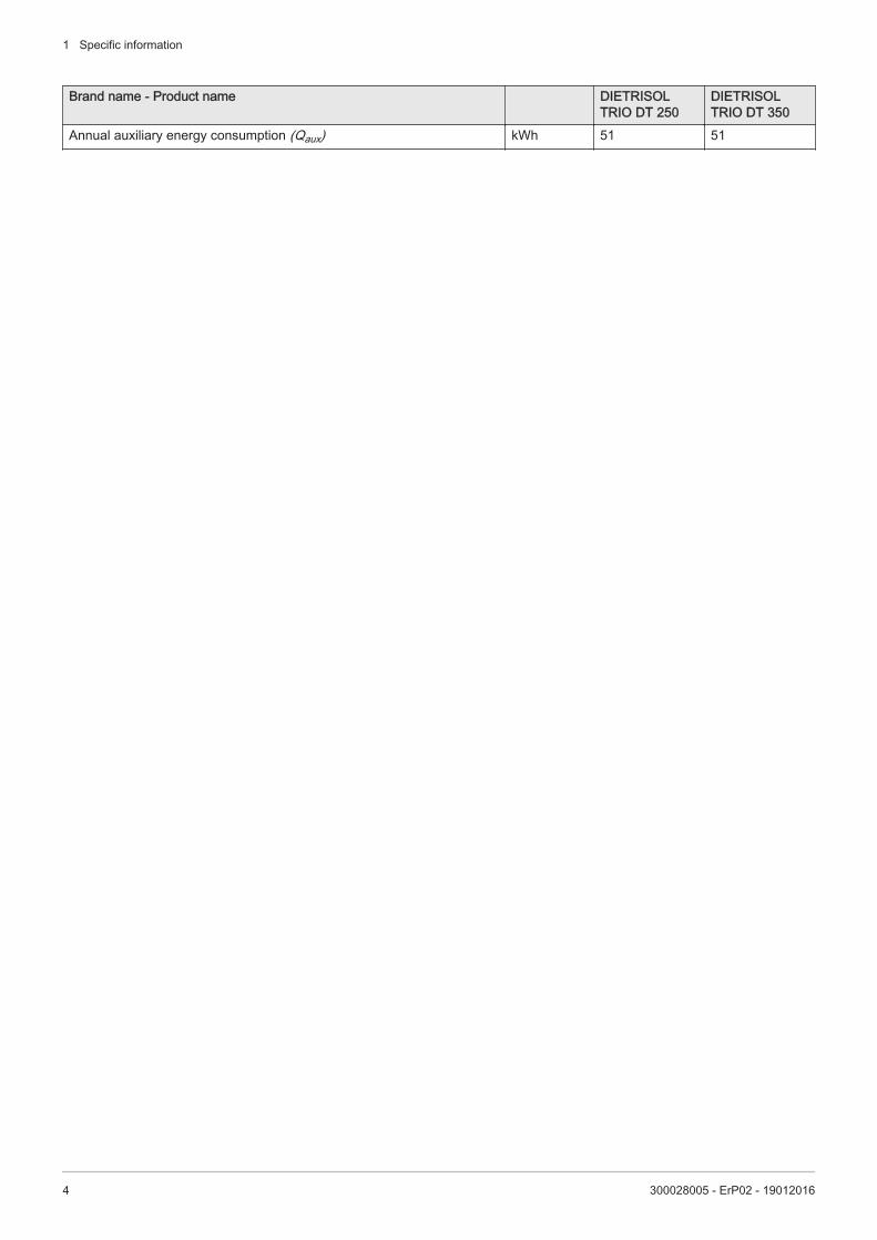
1.6 Product fiche - Solar devices
Tab.2 Product fiche for solar devicesBrand name - Product name DIETRISOL
TRIO DT 250DIETRISOL TRIO DT 350
Solar hot water storage tank - Energy efficiency class C D
Solar hot water storage tank - Standing loss W 92 113Solar hot water storage tank - Storage volume l
m32470.247
3500.350
Power consumption - Pump W 23 23Power consumption - Standby W 0.54 0.54
1 Specific information
300028005 - ErP02 - 19012016 3
Brand name - Product name DIETRISOL TRIO DT 250
DIETRISOL TRIO DT 350
Annual auxiliary energy consumption (Qaux) kWh 51 51
1 Specific information
4 300028005 - ErP02 - 19012016

© CopyrightAll technical and technological information contained in these technical instructions, as well as anydrawings and technical descriptions supplied, remain our property and shall not be multipliedwithout our prior consent in writing.Subject to alterations.
16/07/2015
DE DIETRICH THERMIQUE
57, rue de la Gare F- 67580 MERTZWILLER - BP 30
AD
001N
U-A
J
DUEDI S.r.l.
DE DIETRICH SERVICE
BDR Thermea (Czech republic) s.r.o
www.duediclima.it
www.dedietrich.cz
Distributore Ufficiale Esclusivo
De Dietrich-Thermique Italia
www.dedietrich-heiztechnik.com
Freecall 0800 / 201608
Jeseniova 2770/56
130 00 Praha 3
+49 (0)25 72 / 9161-0
+49 (0)25 72 / 9161-102
Via Passatore, 12 - 12010
San Defendente di Cervasca
CUNEO+39 0171 857170
+39 0171 687875
+420 271 001 627
IT
DE DIETRICH THERMIQUE Iberia S.L.U.www.dedietrich-calefaccion.es
C/Salvador Espriu, 11
08908 L’HOSPITALET de LLOBREGAT+34 935 475 850
ES
+7 (495) 221-31-51
CZ
DE DIETRICH THERMIQUE S.A.S
300028005-001-05