NTC Siemens
164
Selector Guide 11 Applications 19 General Technical Information 23 Data Sheets 45 Standardized R/T Characteristics 107 Mounting Instructions 139 Quality 145 Environmental Protection, Climatic Conditions 151 , 153 Taping and Packing 155 Symbols and Terms 161 Subject Index 163 Contents 5 Index of Types 9
-
Upload
kipkoechrotich -
Category
Documents
-
view
352 -
download
24
description
ccccccccccccccccccccccccccccccc
Transcript of NTC Siemens
Selector Guide 11Applications 19
General Technical Information 23
Data Sheets 45
Standardized R/T Characteristics 107
Mounting Instructions 139Quality 145Environmental Protection, Climatic Conditions 151, 153
Taping and Packing 155Symbols and Terms 161Subject Index 163
Contents 5Index of Types 9
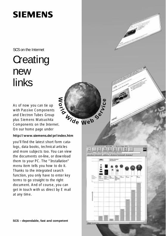
Creatingnewlinks
As of now you can tie upwith Passive Componentsand Electron Tubes Groupplus Siemens Matsushita Components on the Internet. On our home page under
http://www.siemens.de/pr/index.htm
you’ll find the latest short form cata-logs, data books, technical articlesand more subjects too. You can viewthe documents on-line, or downloadthem to your PC. The “Installation“menu item tells you how to do it.Thanks to the integrated search function, you only have to enter keyterms to go straight to the right document. And of course, you canget in touch with us direct by E mailat any time.
Wo
rld
Wide Web Ser
vic
e
SCS – dependable, fast and competent
SCS on the Internet

NTC Thermistors

SCS – dependable, fast and competent
Now order even more
We’ve reallygot things in storeWhen you need bigger batches thanusual, we don’t leave you with emptyhands. We’ve pushed up maximumorder quantities quite a bit, all of tentimes for ceramic chip capacitors forexample. But we’ve got lots more in
store for you, like SCS depots rightthere in our plants, extra stock withdistributors, and experienced salesengineers on the spot around theworld. An extensive range of non-SCScomponents is available too – justcontact us.
Co
nten
ts
Contents
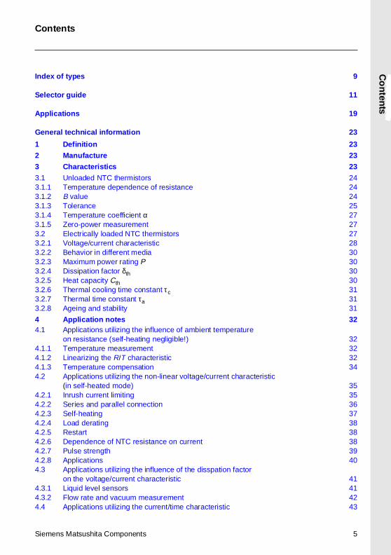
Index o f types 9
Selector gu ide 11
App lications 19
General technical information 23
1 Definition 23
2 Manufacture 23
3 Characteristics 23
3.1 Unloaded NTC thermistors 243.1.1 Temperature dependence of resistance 243.1.2 B value 243.1.3 Tolerance 253.1.4 Temperature coefficient α 273.1.5 Zero-power measurement 273.2 Electrically loaded NTC thermistors 273.2.1 Voltage/current characteristic 283.2.2 Behavior in different media 303.2.3 Maximum power rating P 303.2.4 Dissipation factor δth 303.2.5 Heat capacity Cth 303.2.6 Thermal cooling time constant τc 313.2.7 Thermal time constant τa 313.2.8 Ageing and stability 31
4 App lication no tes 324.1 Applications utilizing the influence of ambient temperature
on resistance (self-heating negligible!) 324.1.1 Temperature measurement 324.1.2 Linearizing the R/T characteristic 324.1.3 Temperature compensation 344.2 Applications utilizing the non-linear voltage/current characteristic
(in self-heated mode) 354.2.1 Inrush current limiting 354.2.2 Series and parallel connection 364.2.3 Self-heating 374.2.4 Load derating 384.2.5 Restart 384.2.6 Dependence of NTC resistance on current 384.2.7 Pulse strength 394.2.8 Applications 404.3 Applications utilizing the influence of the disspation factor
on the voltage/current characteristic 414.3.1 Liquid level sensors 414.3.2 Flow rate and vacuum measurement 424.4 Applications utilizing the current/time characteristic 43
Siemens Matsushita Components 5
Contents
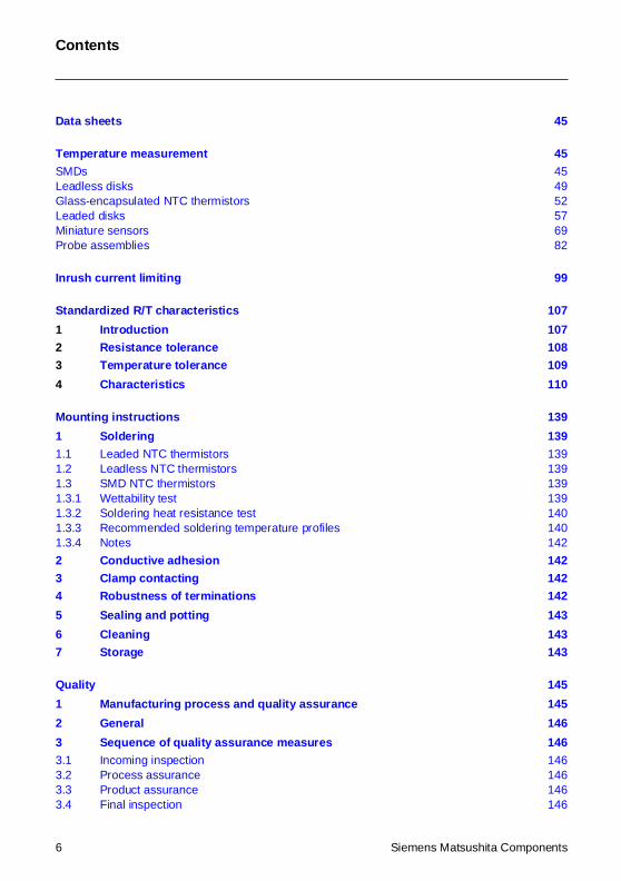
Data sheets 45
Temperature measurement 45
SMDs 45Leadless disks 49Glass-encapsulated NTC thermistors 52Leaded disks 57Miniature sensors 69Probe assemblies 82
Inrush current limit ing 99
Standardized R/T characteristics 107
1 Introduc tion 107
2 Resistance tolerance 108
3 Temperature tolerance 109
4 Characteristics 110
Mount ing instruct ions 139
1 Solder ing 139
1.1 Leaded NTC thermistors 1391.2 Leadless NTC thermistors 1391.3 SMD NTC thermistors 1391.3.1 Wettability test 1391.3.2 Soldering heat resistance test 1401.3.3 Recommended soldering temperature profiles 1401.3.4 Notes 142
2 Cond uct ive adhe sion 142
3 Clamp co ntacting 142
4 Robu stness of terminations 142
5 Sealing and p otting 143
6 Cleaning 143
7 Storage 143
Quali ty 145
1 Manufacturing p rocess and qu al ity ass urance 145
2 General 146
3 Sequen ce of qua li ty assu rance measures 146
3.1 Incoming inspection 1463.2 Process assurance 1463.3 Product assurance 1463.4 Final inspection 146
6 Siemens Matsushita Components
Contents
4 Delivery qua li ty 146
5 Sampling inspec tion 147
6 Classificat ion o f defects 147
7 AQL va lues 147
8 Inco ming inspec tion by the cus tomer 148
9 Reliabil ity 149
10 Iden tif ication and traceabili ty 149
11 Supp lementary information 150
Env ironmental p rotection measures 151
Climat ic cond itions 153
1 Reliabil ity data 153
2 Operating temperature range / ambient temperatures 153
Taping and pack ing 155
1 Taping of SMD thermistors 155
2 Taping of radial-lead NTC thermistors 157
3 Taping of M 87 NTC thermistors 160
4 Pack ing codes 160
Symbols and terms 161
Sub ject index 163
Siemens Matsushita Components 7
SCS – dependable, fast and competent
Now twice as many
Siemens Matsushita ComponentsCOMPONENTS
+S M
2,000 PTC thermistors at once
A hot tip in PTCs for overloadprotection: our new maximum orderlevel of 2,000 pieces. And withmore than 50 different models,we’ve got a lot more to offer too.Maximum operating voltages from12 to 550 V, rated currents up to 2.5A, maximum switching currents of15 A, plus a broad selection of lea-ded versions and SMDs.
Siemens Matsushita Components 9
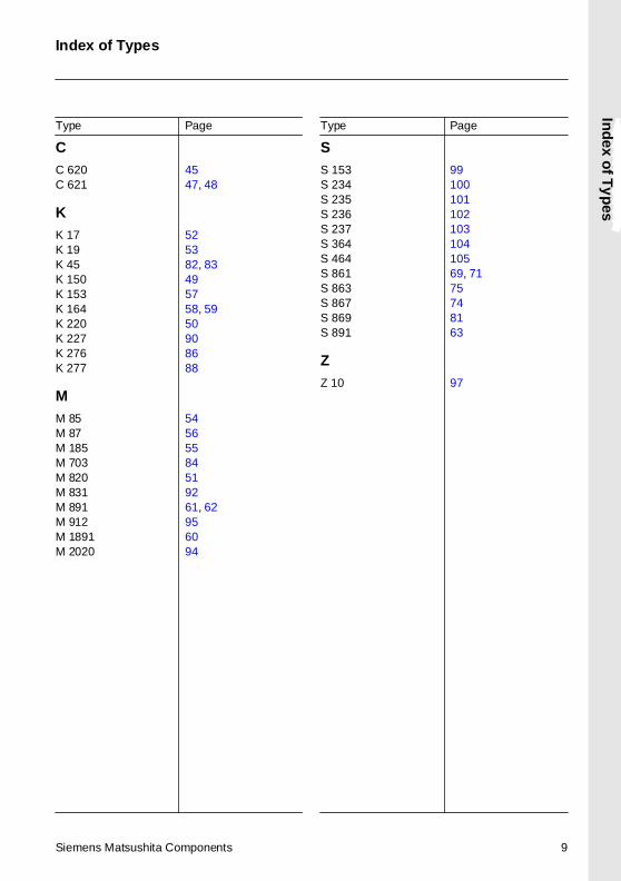
Type Page Type Page
CC 620 45C 621 47, 48
KK 17 52K 19 53K 45 82, 83K 150 49K 153 57K 164 58, 59K 220 50K 227 90K 276 86K 277 88
MM 85 54M 87 56M 185 55M 703 84M 820 51M 831 92M 891 61, 62M 912 95M 1891 60M 2020 94
SS 153 99S 234 100S 235 101S 236 102S 237 103S 364 104S 464 105S 861 69, 71S 863 75S 867 74S 869 81S 891 63
ZZ 10 97
Index of Types
Ind
ex of T
yp
es

SCS – dependable, fast and competent
A whole lot of ring core chokes
Siemens Matsushita ComponentsCOMPONENTS
+S M
Chokes to your choice
You urgently need particular ringcore chokes? That’s no problem, wehave 200,000 pieces in stock anddeliver reliably through SCS. Ourautomated production guarantees
the best of reliability too. It turns outchokes in different versions: flat andupright, with current rated from 0.4to 16 A. UL and VDE approved, andcomplying with the latest EMC stan-dards of course.
Selecto
r Gu
ide
Selector Guide
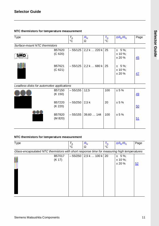
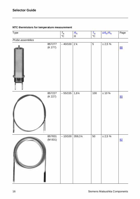
NTC thermistors for temperature measurement
Type TA°C
RNΩ
TN°C
∆RN/RN Page
Surface-mount NTC thermistors
B57620(C 620)
– 55/125 2,2 k … 220 k 25 ± 5 %;± 10 %;± 20 % 45
B57621(C 621)
– 55/125 2,2 k … 680 k 25 ± 5 %;± 10 %;± 20 % 47
Leadless disks for automotive applications
B57150(K 150)
– 55/155 12,5 100 ± 5 %49
B57220(K 220)
– 55/250 2,5 k 20 ± 5 %50
B57820(M 820)
– 55/155 39,60 … 144 100 ± 5 %51
NTC thermistors for temperature measurement
Type TA°C
RNΩ
TN°C
∆RN/RN Page
Glass-encapsulated NTC thermistors with short response time for measuring high temperatures
B57017(K 17)
– 55/250 2,5 k … 100 k 20 ± 5 %;± 10 %;± 20 % 52
Siemens Matsushita Components 11
Selector Guide
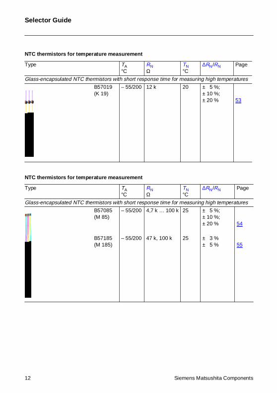
Glass-encapsulated NTC thermistors with short response time for measuring high temperatures
B57019(K 19)
– 55/200 12 k 20 ± 5 %;± 10 %;± 20 % 53
NTC thermistors for temperature measurement
Type TA°C
RNΩ
TN°C
∆RN/RN Page
Glass-encapsulated NTC thermistors with short response time for measuring high temperatures
B57085(M 85)
– 55/200 4,7 k … 100 k 25 ± 5 %;± 10 %;± 20 % 54
B57185(M 185)
– 55/200 47 k, 100 k 25 ± 3 %± 5 % 55
NTC thermistors for temperature measurement
Type TA°C
RNΩ
TN°C
∆RN/RN Page
12 Siemens Matsushita Components
Selector Guide
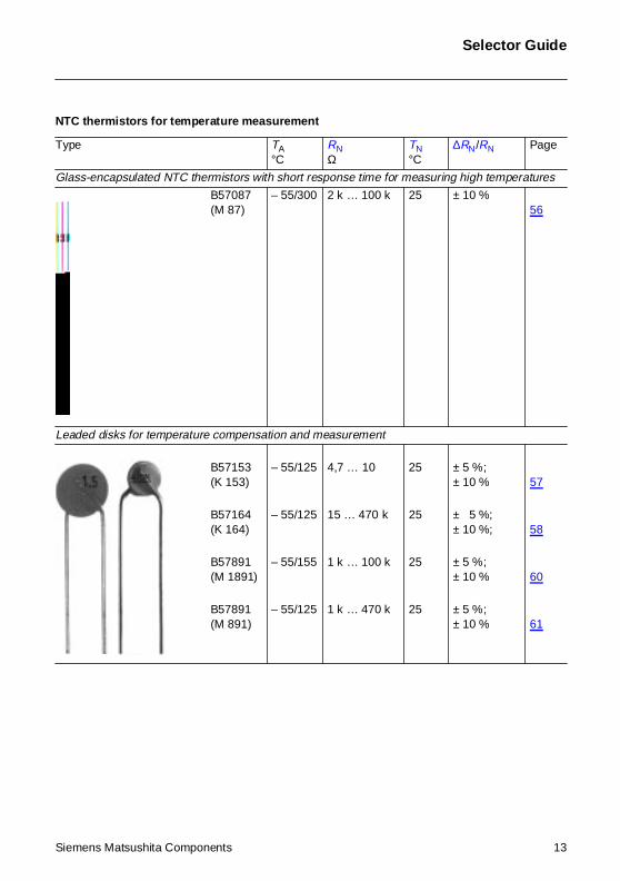
Glass-encapsulated NTC thermistors with short response time for measuring high temperatures
B57087(M 87)
– 55/300 2 k … 100 k 25 ± 10 %56
Leaded disks for temperature compensation and measurement
B57153(K 153)
– 55/125 4,7 … 10 25 ± 5 %;± 10 % 57
B57164(K 164)
– 55/125 15 … 470 k 25 ± 5 %;± 10 %; 58
B57891(M 1891)
– 55/155 1 k … 100 k 25 ± 5 %;± 10 % 60
B57891(M 891)
– 55/125 1 k … 470 k 25 ± 5 %;± 10 % 61
NTC thermistors for temperature measurement
Type TA°C
RNΩ
TN°C
∆RN/RN Page
Siemens Matsushita Components 13
Selector Guide
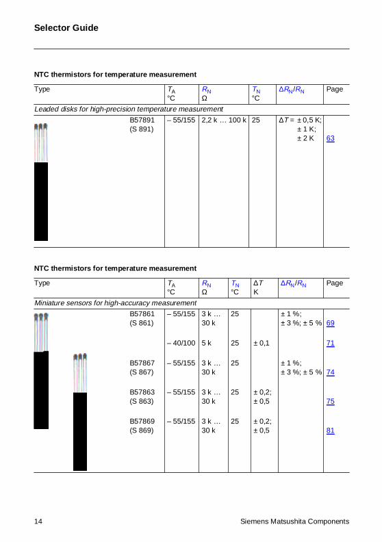
Leaded disks for high-precision temperature measurement
B57891(S 891)
– 55/155 2,2 k … 100 k 25 ∆T = ± 0,5 K;± 1 K;± 2 K 63
NTC thermistors for temperature measurement
Type TA°C
RNΩ
TN°C
∆TK
∆RN/RN Page
Miniature sensors for high-accuracy measurement
B57861(S 861)
– 55/155 3 k …30 k
25 ± 1 %;± 3 %; ± 5 % 69
– 40/100 5 k 25 ± 0,1 71
B57867(S 867)
– 55/155 3 k …30 k
25 ± 1 %;± 3 %; ± 5 % 74
B57863(S 863)
– 55/155 3 k …30 k
25 ± 0,2;± 0,5 75
B57869(S 869)
– 55/155 3 k …30 k
25 ± 0,2;± 0,5 81
NTC thermistors for temperature measurement
Type TA°C
RNΩ
TN°C
∆RN/RN Page
14 Siemens Matsushita Components
Selector Guide
NTC thermistors for temperature measurement
Type TA°C
RNΩ
TN°C
∆RN/RN Page
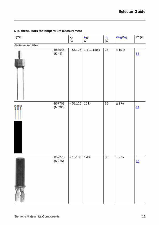
Probe assemblies
B57045(K 45)
– 55/125 1 k … 150 k 25 ± 10 %82
B57703(M 703)
– 55/125 10 k 25 ± 2 %84
B57276(K 276)
– 10/100 1704 80 ± 2 %86
Siemens Matsushita Components 15
Selector Guide
Probe assemblies
B57277(K 277)
– 40/100 2 k 5 ± 2,5 %88
B57227(K 227)
– 55/155 1,8 k 100 ± 10 %90
B57831(M 831)
– 10/100 359,3 k 50 ± 2,5 %92
NTC thermistors for temperature measurement
Type TA°C
RNΩ
TN°C
∆RN/RN Page
16 Siemens Matsushita Components
Selector Guide
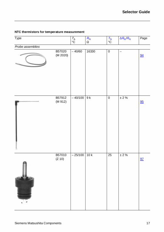
Probe assemblies
B57020(M 2020)
– 40/60 16330 0 –94
B57912(M 912)
– 40/100 9 k 0 ± 2 %95
B57010(Z 10)
– 25/100 10 k 25 ± 2 %97
NTC thermistors for temperature measurement
Type TA°C
RNΩ
TN°C
∆RN/RN Page
Siemens Matsushita Components 17
Selector Guide
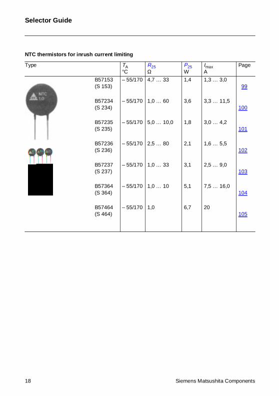
NTC thermistors for inrush current limiting
Type TA°C
R25Ω
P25W
ImaxA
Page
B57153(S 153)
– 55/170 4,7 … 33 1,4 1,3 … 3,099
B57234(S 234)
– 55/170 1,0 … 60 3,6 3,3 … 11,5100
B57235(S 235)
– 55/170 5,0 … 10,0 1,8 3,0 … 4,2101
B57236(S 236)
– 55/170 2,5 … 80 2,1 1,6 … 5,5102
B57237(S 237)
– 55/170 1,0 … 33 3,1 2,5 … 9,0103
B57364(S 364)
– 55/170 1,0 … 10 5,1 7,5 … 16,0104
B57464(S 464)
– 55/170 1,0 6,7 20105
18 Siemens Matsushita Components
Ap
plications
Applications
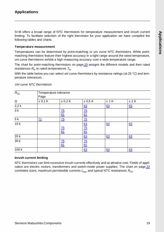
S+M offers a broad range of NTC thermistors for temperature measurement and inrush currentlimiting. To facilitate selection of the right thermistor for your application we have compiled thefollowing tables and charts.
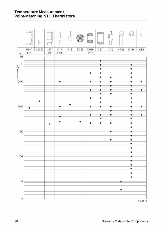
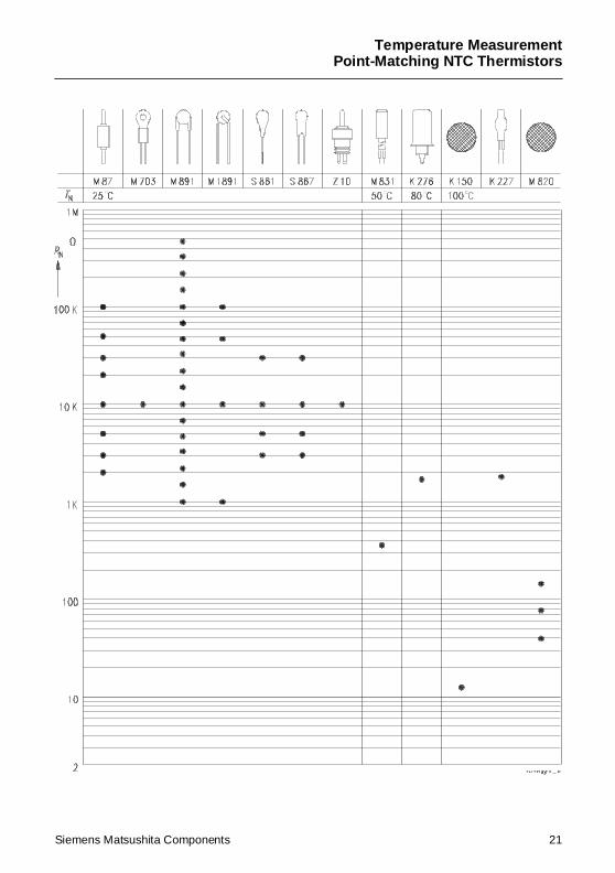
Temperature measurement
Temperatures can be determined by point-matching or uni curve NTC thermistors. While point-matching thermistors feature their highest accuracy in a tight range around the rated temperature,uni curve thermistors exhibit a high measuring accuracy over a wide temperature range.
The chart for point-matching thermistors on page 20 assigns the different models and their ratedresistances RN to rated temperatures TN.
With the table below you can select uni curve thermistors by resistance ratings (at 25 °C) and tem-perature tolerances .
Uni curve NTC thermistors
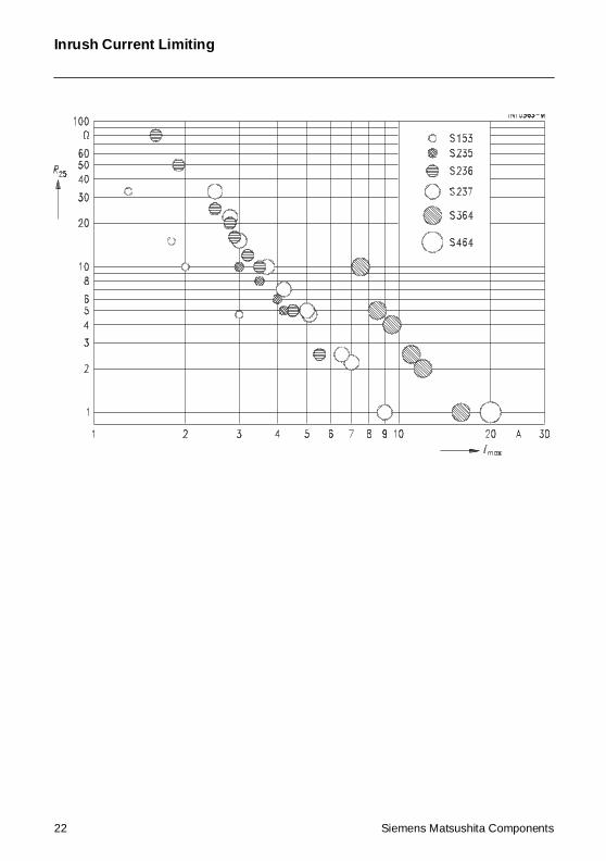
Inrush current limiting
NTC thermistors can limit excessive inrush currents effectively and at attrative cost. Fields of appli-cation are electric motors, transformers and switch-mode power supplies. The chart on page 22correlates sizes, maximum permissible currents Imax and typical NTC resistances R25.
R25 Temperature tolerancePage
Ω ± 0,1 K ± 0,2 K ± 0,5 K ± 1 K ± 2 K
2,2 k 63 63 63
3 k 7581
7581
5 k 71 75 75
10 k7581
637581
63 63
20 k 63 63 63
30 k 7581
7581
100 k 63 63 63
Siemens Matsushita Components 19
Temperature MeasurementPoint-Matching NTC Thermistors
20 Siemens Matsushita Components
Temperature MeasurementPoint-Matching NTC Thermistors
Siemens Matsushita Components 21
Inrush Current Limiting
22 Siemens Matsushita Components
Gen
eral Tech
nic
al Info
rmatio
n
General Technical Information
1 Definition
As defined by IEC 539, CECC 43 000 and DIN 44 070, NTC (Negative Temperature Coefficient)thermistors are thermally sensitive semiconductor resistors which show a decrease in resistance astemperature increases. With – 2%/K to – 6 %/K, the negative temperature coefficients of resistanceare about ten times greater than those of metals.
Changes in the resistance of the NTC thermistor can be brought about either externally by a changein ambient temperature or internally by self-heating resulting from a current flowing through the de-vice. All practical applications are based on this behavior.
NTC thermistors are made of polycrystalline mixed oxide ceramics. The conduction mechanisms inthis material are quite complex, i.e. either extrinsic or intrinsic conduction may occur. In many casesNTC thermistors have a spinell structure and then show valence conduction effects.
2 Manufacture
S + M thermistors are produced from carefully selected and tested raw materials. The starting ma-terials are different oxides of metals such as manganese, iron, cobalt, nickel, copper and zinc, towhich chemically stabilizing oxides may be added to achieve better reproducibility and stability ofthe thermistor characteristics.
The oxides are milled to a powdery mass, mixed with a plastic binder and then compressed into thedesired shape. Standard shapes are:
Disks: The thermistor material is compressed under very high pressure on pelleting machines toproduce round, flat pieces.
Wafers: The ceramic material is compression-molded or drawn and then cut to the required shape.
Beads: The oxide/binder mixture is deposited in the form of small ellipsoids on two fine parallelwires made of platinum alloy.
The blanks are then sintered at high temperatures (between 1000 and 1400 °C) to produce the poly-crystalline thermistor body. Disks are contacted by baking a silver paste onto the flat surfaces. Withbeads the wires embedded in the sintered body serve as contacts. Depending on the application,the thermistors are fitted with leads or tab connectors, coated or additionally incorporated in differ-ent kinds of housing. Finally the thermistors are subjected to a special ageing process to ensurehigh stability of the electrical values. Otherwise the NTC resistance would possibly change even atroom temperature due to solid-state reactions in the polycrystalline material.
A flow chart in the quality section of this book (see page 145) shows the individual processing stepsin detail. The chart also illustrates the extensive quality assurance measures taken during manu-facture to guarantee the constantly high quality level of our thermistors.
3 Characteristics
A current flowing through a thermistor may cause sufficient heating to raise the thermistor’s temper-ature above the ambient. As the effects of self-heating are not always negligible (or may even beintended), a distinction has to be made between the characteristics of an electrically loaded ther-mistor and those of an unloaded thermistor. The properties of an unloaded thermistor are alsotermed “zero-power characteristics”.
Siemens Matsushita Components 23
24
3.1 Unloaded NTC
3.1.1 Temperature d
The dependence of the
RT NTC resistanc
RN NTC resistanc
T, TN Temperature i
B B value, mater
e Base of natura
The actual characteristponential relation, as thproach is only suitable with sufficient accuracy
For practical applicatiocomplicated approacherelation is given in tabuR/T curves (page 110 fmost accuracy; they ar
3.1.2 B value
As already mentioned portant to know to whicsurement at temperatu
The B value for a partic(R1) and 100 ˚C (R2) a
RT RN eB 1
T---
1TN-------–
⋅
⋅=
BT1 T2⋅T2 T1–------------------ ln
R1
R2-------⋅ -= =
General Technical
thermistors
ependence of resistance
resistance on temperature can be approximated by the following equation:
e in Ω at temperature T in K
e in Ω at rated temperature TN in K
n K
ial-specific constant of the NTC thermistor
l logarithm (e = 2,71828)
ic of an NTC thermistor can, however, only be roughly described by the ex-e material parameter B in reality also depends on temperature. So this ap-for describing a restricted range around the rated temperature or resistance.
ns a more precise description of the real R/T curve is required. Either mores (e.g the Steinhart-Hart equation) are used or the resistance/temperaturelated form. Subsequent to the data sheet section you will find tables for realf). These standardized curves have been experimentally determined with ut-e also available for temperature increments of 1 degree.
in the paragraph above, the B value depends on temperature. Thus it is im-h temperature B is referred. The specifications in this data book refer to mea-res of 25 ˚C (T1) and 100 ˚C (T2). Symbol: B25/100.
ular NTC thermistor can be determined by measuring the resistance at 25 ˚Cnd inserting these resistance values into the following equation:
(1)
25( 273,15 )+ 100( 273,15 )+⋅75
--------------------------------------------------------------------------------------------- lnR25
R100------------⋅ 1483,4 ln
R25
R100------------⋅ = (2)
Information
Siemens Matsushita Components
Siemens Matsushita C
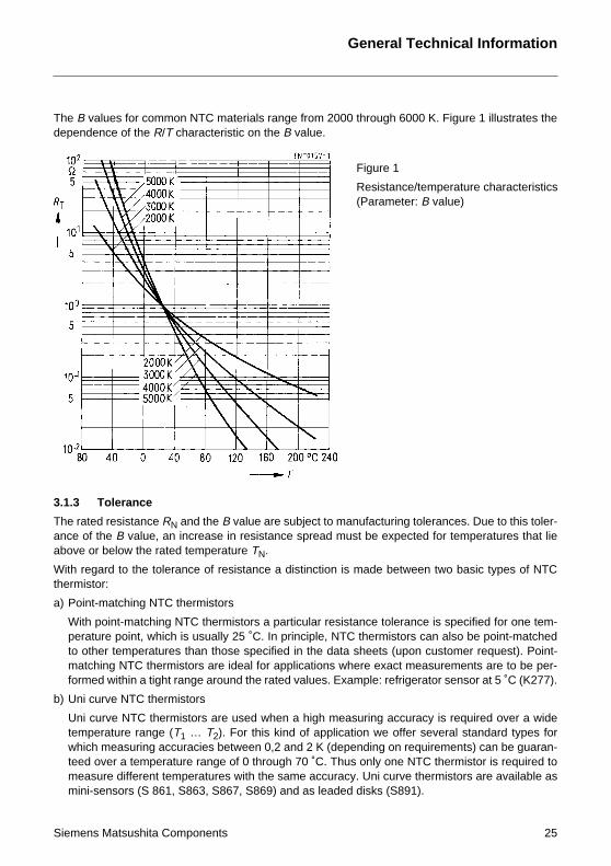
The B values for commdependence of the R/T
3.1.3 Tolerance
The rated resistance Rance of the B value, aabove or below the rate
With regard to the tolethermistor:
a) Point-matching NTC
With point-matchingperature point, whicto other temperaturematching NTC thermformed within a tight
b) Uni curve NTC therm
Uni curve NTC thertemperature range which measuring acteed over a temperameasure different temini-sensors (S 861
on NTC materials range from 2000 through 6000 K. Figure 1 illustrates the characteristic on the B value.
Figure 1
Resistance/temperature characteristics(Parameter: B value)
General Technical Information
omponents 25
N and the B value are subject to manufacturing tolerances. Due to this toler-n increase in resistance spread must be expected for temperatures that lied temperature TN.
rance of resistance a distinction is made between two basic types of NTC
thermistors
NTC thermistors a particular resistance tolerance is specified for one tem-h is usually 25 ˚C. In principle, NTC thermistors can also be point-matcheds than those specified in the data sheets (upon customer request). Point-istors are ideal for applications where exact measurements are to be per-
range around the rated values. Example: refrigerator sensor at 5 ˚C (K277).
istors
mistors are used when a high measuring accuracy is required over a wide(T1 … T2). For this kind of application we offer several standard types forcuracies between 0,2 and 2 K (depending on requirements) can be guaran-ture range of 0 through 70 ˚C. Thus only one NTC thermistor is required tomperatures with the same accuracy. Uni curve thermistors are available as, S863, S867, S869) and as leaded disks (S891).
26
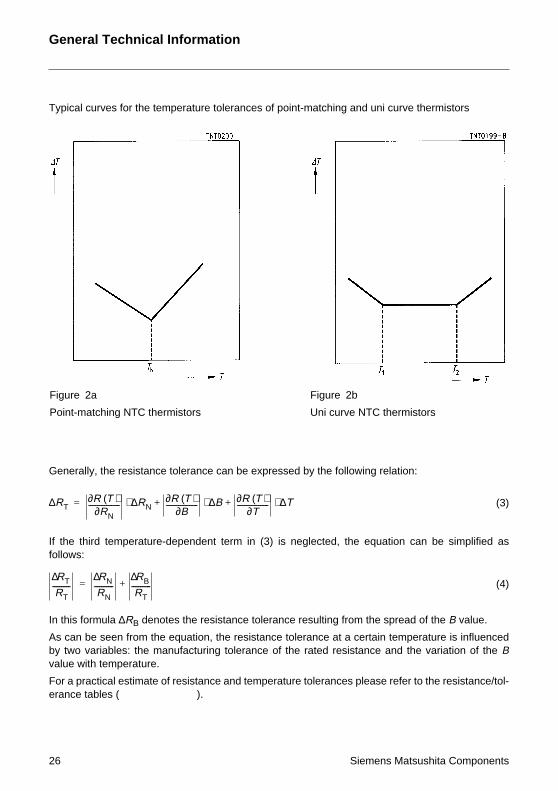
Typical curves for the t
Generally, the resistan
If the third temperaturfollows:
In this formula ∆RB den
As can be seen from thby two variables: the mvalue with temperature
For a practical estimateerance tables (
Figure 2a
Point-matching NTC th
RT∆ R T( )∂RN∂------------------ RN∆⋅ +=
RT∆RT
----------RN∆RN
-----------RB∆RT
-----------+=
General Technical
emperature tolerances of point-matching and uni curve thermistors
Information
Siemens Matsushita Components
ce tolerance can be expressed by the following relation:
e-dependent term in (3) is neglected, the equation can be simplified as
otes the resistance tolerance resulting from the spread of the B value.
e equation, the resistance tolerance at a certain temperature is influencedanufacturing tolerance of the rated resistance and the variation of the B
.
of resistance and temperature tolerances please refer to the resistance/tol-).
ermistors
Figure 2b
Uni curve NTC thermistors
R T( )∂B∂------------------ B∆⋅ R T( )∂
T∂------------------ T∆⋅+ (3)
(4)
Siemens Matsushita C
3.1.4 Temperature c
The temperature coeffithe change in tempera
By means of this equatperature intervals.
For practical applicatioused; the temperature imation formulae given
3.1.5 Zero-power m
The zero-power resistatrical load kept so smather decreased. At tooeffect (see 3.2). Whenmeasuring lines must b
Example: For S861, R2
3.2 Electrically loa
When a current flows thtion. This self-heating etion factor δ and the ge
The general rule is:
The smaller the devicepower).
α 1R----·
dRdT--------=
T∆ 1α R⋅------------ R∆⋅=
oefficien t αcient of resistance is defined as the relative change in resistance referred toture.
ion resistance and temperature tolerances can be calculated for small tem-
n we recommend that the standardized R/T curves (see page 107 ff) aresteps tabulated there are small enough to permit calculation by the approx- above.
easurement
nce is the resistance value measured at a given temperature T with the elec-ll that there is no noticeable change in the resistance value if the load is fur- high a measuring load the test results will be distorted by the self-heating a low-resistance NTC thermistor is to be measured, the resistance of thee taken into account.
5 = 10 kΩ the measuring current IMeas is ≤ 100 µA.
ded NTC thermistors
rough the thermistor, the device will heat up more or less by power dissipa-ffect depends not only on the load applied, but also on the thermal dissipa-ometry of the thermistor itself.
, the smaller is the permissible maximum load and the measuring load (zero
(5)
R∆ α R T∆⋅ ⋅= (6)
General Technical Information
omponents 27
28
The following general r
P Electrical powV InstantaneousI InstantaneousdH/dt Change of stoδ Dissipation facT InstantaneousTA Ambient tempCth Heat capacity dT/dt Change of tem
3.2.1 Voltage/curren
If a constant electrical erably, but this changepower is dissipated by
In case of thermal equi
and with V = R · I :
or
This is the socalled parature-dependent NTC lated for different ambi
P V I Hdtd
-------=⋅ δth ⋅= =
V I⋅ δth T TA–( )⋅=
Iδth T TA–( )⋅
R T( )-----------------------------------=
V δth T TA–( ) R⋅ ⋅=
General Technical
ule applies to self-heating of an NTC thermistor by an electrical load:
er applied value of NTC voltage value of NTC currentred thermal energy with timetor of NTC thermistor temperature of NTC thermistoreratureof NTC thermistorperature with time
t characteristic
power is applied to the thermistor, its temperature will first increase consid- declines with time. After some time a steady state will be reached where thethermal conduction or convection.
librium dT/dt equals 0 and thus one obtains
ametric description of the voltage/current curve with R (T) being the temper-resistance. With the aid of the above equations these curves can be calcu-ent temperatures.
T TA–( ) CthTdtd
-------⋅+ (7)
(8)
(9a)
T( ) (9b)
Information
Siemens Matsushita Components
Siemens Matsushita C
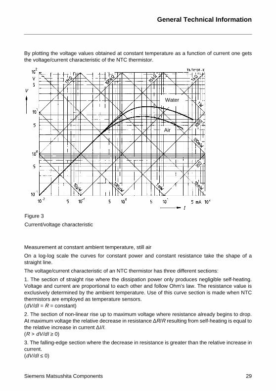
By plotting the voltagethe voltage/current cha
Measurement at consta
On a log-log scale thestraight line.
The voltage/current ch
1. The section of straigVoltage and current arexclusively determinedthermistors are employ(dV/dI = R = constant)
2. The section of non-lAt maximum voltage ththe relative increase in(R > dV/dI ≥ 0)
3. The falling-edge seccurrent.(dV/dI ≤ 0)
Figure 3
Current/voltage charac
values obtained at constant temperature as a function of current one getsracteristic of the NTC thermistor.
Water
Air
General Technical Information
omponents 29
nt ambient temperature, still air
curves for constant power and constant resistance take the shape of a
aracteristic of an NTC thermistor has three different sections:
ht rise where the dissipation power only produces negligible self-heating.e proportional to each other and follow Ohm’s law. The resistance value is by the ambient temperature. Use of this curve section is made when NTCed as temperature sensors.
inear rise up to maximum voltage where resistance already begins to drop.e relative decrease in resistance ∆R/R resulting from self-heating is equal to current ∆I/I.
tion where the decrease in resistance is greater than the relative increase in
teristic
30
3.2.2 Behavior in dif
As shown by equationresistance R (T) but alsize, shape and leads
The voltage/current cuthe dissipation factor inrent. The opposite app
The voltage/current cumeans that NTC thermmeasurement or for ga
3.2.3 Maximum pow
P is the maximum powature with its own tempambient temperature, m
With known dissipation
Pmax = δth (Tmax – TA)
3.2.4 Dissipation fac
The dissipation factor δchange in the thermistothe load which causes the dissipation factor, t
δth = dP/dT
For measuring δth the tue measured at T2 = 8
T2 Body temperaT1 Ambient temp
3.2.5 Heat capacity
The heat capacity Cth perature by 1 K. Cth is
The relationship betweby:
Cth = δth · τth
δthV I⋅
T2 T1–------------------
PT2 T–---------------= =
CthH∆T∆--------
=
General Technical
ferent media
s (9a) and (9b) the voltage/current curve is influenced not only by the NTCso by the dissipation factor δth. The dissipation factor, in turn, depends onof the the device as well as on the medium surrounding the thermistor.
rves specified in the data sheets apply to still air. In stirred air or in a liquidcreases and the V/I curve shifts towards higher values of voltage and cur-
lies when the thermistor is suspended in a vacuum.
rve thus indicates by which medium the thermistor is surrounded. Thisistors can be used for sensing the flow rate of gases or liquids, for vacuums analysis.
er rating P
er an NTC thermistor is capable of handling at a particular ambient temper-erature not exceeding the maximum category temperature. In addition to the
ainly the dissipation factor δth determines the power handling capability.
factor δth the maximum power handling capability can be calculated by:
(10)
tor δth
th is defined as the ratio of the change in power dissipation and the resultantr’s body temperature. It is expressed in mW/K and serves as a measure fora thermistor in steady state to raise its body temperature by 1 K. The higherhe more heat is dissipated by the thermistor to the environment.
(11)
hermistor is loaded such that the ratio V/I corresponds to the resistance val-5 ˚C.
ture of the NTC thermistor (85 ˚C)erature
C
1--- (12)
Information
Siemens Matsushita Components
th
is a measure for the amount of heat required to raise the NTC’s mean tem-stated in mJ/K.
en heat capacity, dissipation factor and thermal time constant is expressed
(14)
(13)
General Technical Information
3.2.6 Thermal cooling time constant τc
The thermal cooling time constant refers to the time necessary for an unloaded thermistor to varyits temperature by 63,2% of the difference between its mean temperature and the ambient temper-ature.
τc depends to a large extent on the component design. The values of τc specified in this data bookhave been determined in still air at an ambient temperature of 25 °C.
The NTC thermistor is internally heated to 85 °C to measure subsequently the time it requires tocool down to 47,1 °C at an ambient temperature of 25 °C. This adjustment to the ambient is asymp-totic and occurs all the faster, the smaller the device is.
3.2.7 Thermal time constant τa
The thermal time constant refers to the time it takes an unloaded thermistor to raise its body tem-perature from 25 °C to 62,9 °C when it is immersed in a medium having a temperature of 85 °C.Equally to thermal cooling time constant, τa depends on the medium surrounding the device. Themedium used for measuring τa (e.g. water) is specified in the data sheets.
Determining the thermal time constant:
a) The zero-power-resistance is measured at 25 °C.The zero-power resistance is measured at 62,9 °C.
b) The NTC thermistor is immersed in a liquid bath with a temperature of (25 ± 0,1)°C until it hasassumed the same temperature as the liquid.
c) The NTC thermistor is then immediately transferred into a second bath with a temperature of(85 ± 0,1)°C. Subsequently the time is measured it takes the thermistor to reach again the zero-power resistance measured under a) for 62,9 °C.
The resulting time is the thermal time constant for an external temperature change.
3.2.8 Ageing and stability
At room temperature the polycrystalline material NTC thermistors are made of shows solid-state re-actions which lead to an irreversible change in the characteristics (usually resistance increase,change of B value etc).
Physical reasons for this may be thermal stress causing a change in concentration of lattice imper-fections, oxygen exchange with the environment (with unprotected, non-glass-encapsulated ther-mistors) or diffusion in the contact areas of metallized surface contacts. At low temperatures thesereactions slow down, but at high temperatures they accelerate and finally decline with time. Toenhance long-term stability, our NTC thermistors are subjected to an ageing process directly aftermanufacture.
Siemens Matsushita Components 31
General Technical Information
4 Application notes
4.1 Applications utilizing the influence of ambient temperature on resistance(self-heating negligible!)
4.1.1 Temperature measurement
The high sensitivity of an NTC thermistor makes it an ideal candidate for temperature sensingapplications. These low-cost NTC sensors are usually employed for a temperature range of – 40to + 300 °C.
Selection criteria for NTC thermistors are– temperature range– resistance range– measuring accuracy– environment (surrounding medium)– response time– dimensional requirements.
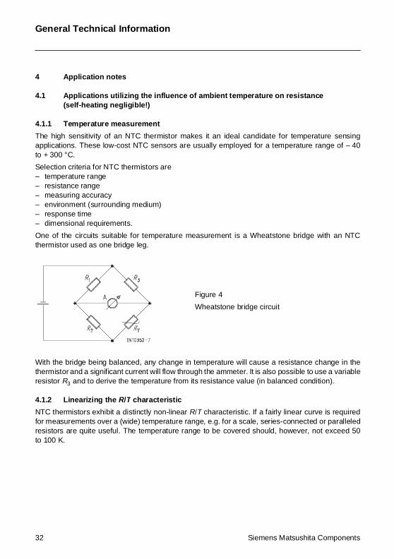
One of the circuits suitable for temperature measurement is a Wheatstone bridge with an NTCthermistor used as one bridge leg.
With the bridge being balanced, any change in temperature will cause a resistance change in thethermistor and a significant current will flow through the ammeter. It is also possible to use a variableresistor R3 and to derive the temperature from its resistance value (in balanced condition).
4.1.2 Linearizing the R/T characteristic
NTC thermistors exhibit a distinctly non-linear R/T characteristic. If a fairly linear curve is requiredfor measurements over a (wide) temperature range, e.g. for a scale, series-connected or paralleledresistors are quite useful. The temperature range to be covered should, however, not exceed 50to 100 K.
Figure 4
Wheatstone bridge circuit
32 Siemens Matsushita Components
Siemens Matsushita C
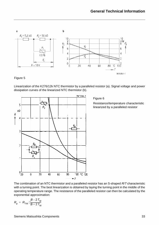
Linearization of the K27dissipation curves of th
The combination of an with a turning point. Thoperating temperature exponential approxima
Figure 5
Rp RTM
B 2TM–
B 2TM+---------------------⋅=
6/12k NTC thermistor by a paralleled resistor (a). Signal voltage and powere linearized NTC thermistor (b).
General Technical Information
omponents 33
NTC thermistor and a paralleled resistor has an S-shaped R/T characteristice best linearization is obtained by laying the turning point in the middle of therange. The resistance of the paralleled resistor can then be calculated by thetion:
Figure 6
Resistance/temperature characteristiclinearized by a paralleled resistor
34
The total resistance of
RTM Resistance va(in K ≅ temper
B B value of the
The rate of rise of the (
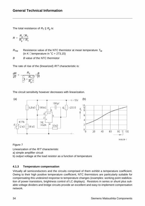
The circuit sensitivity h
Figure 7
Linearization of the R/Ta) simple amplifier circb) output voltage at the
4.1.3 Temperature c
Virtually all semiconduOwing to their high pocompensating this undtion of power transistorable voltage dividers annetwork.
RRp RT⋅Rp RT+--------------------=
RdTd
-------RT
1RT
Rp-------+
2--------------------------–
BT2------⋅=
(a)
General Technical
RT || Rp is:
lue of the NTC thermistor at mean temperature TMature in ˚C + 273,15)
NTC thermistor
linearized) R/T characteristic is:
owever decreases with linearization.
characteristic
(b)
Information
Siemens Matsushita Components
uit load resistor as a function of temperature
ompensation
ctors and the circuits comprised of them exhibit a temperature coefficient.sitive temperature coefficient, NTC thermistors are particularly suitable foresired response to temperature changes (examples: working point stabiliza-s, brightness control of LC displays). Resistors in series or shunt plus suit-d bridge circuits provide an excellent and easy-to-implement compensation
General Technical Information
It is important to match the temperature of the compensating NTC thermistor to that of the compo-nent causing the temperature response. Temperature-compensating thermistors are therefore notonly available in conventional leaded styles, but also incorporated in screw-type housings for at-tachment to heat sinks and as chip version for surface mounting.
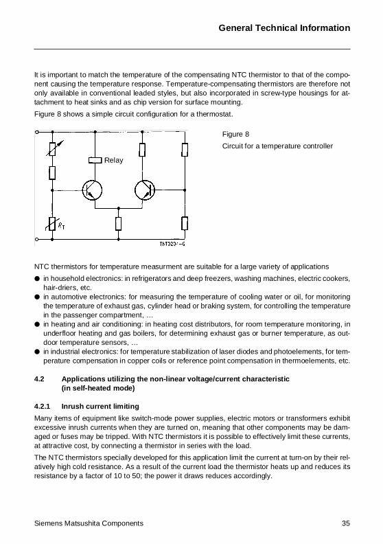
Figure 8 shows a simple circuit configuration for a thermostat.
NTC thermistors for temperature measurment are suitable for a large variety of applications
in household electronics: in refrigerators and deep freezers, washing machines, electric cookers,hair-driers, etc.
in automotive electronics: for measuring the temperature of cooling water or oil, for monitoringthe temperature of exhaust gas, cylinder head or braking system, for controlling the temperaturein the passenger compartment, …
in heating and air conditioning: in heating cost distributors, for room temperature monitoring, inunderfloor heating and gas boilers, for determining exhaust gas or burner temperature, as out-door temperature sensors, …
in industrial electronics: for temperature stabilization of laser diodes and photoelements, for tem-perature compensation in copper coils or reference point compensation in thermoelements, etc.
4.2 Applications utilizing the non-linear voltage/current characteristic (in self-heated mode)
4.2.1 Inrush current limiting
Many items of equipment like switch-mode power supplies, electric motors or transformers exhibitexcessive inrush currents when they are turned on, meaning that other components may be dam-aged or fuses may be tripped. With NTC thermistors it is possible to effectively limit these currents,at attractive cost, by connecting a thermistor in series with the load.
The NTC thermistors specially developed for this application limit the current at turn-on by their rel-atively high cold resistance. As a result of the current load the thermistor heats up and reduces itsresistance by a factor of 10 to 50; the power it draws reduces accordingly.
Figure 8
Circuit for a temperature controller
Relay
Siemens Matsushita Components 35
General Technical Information
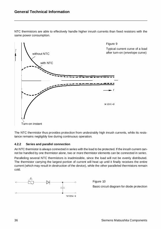
NTC thermistors are able to effectively handle higher inrush currents than fixed resistors with thesame power consumption.
The NTC thermistor thus provides protection from undesirably high inrush currents, while its resis-tance remains negligibly low during continuous operation.
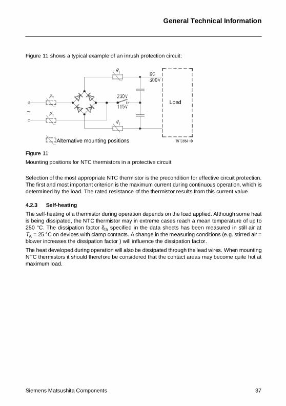
4.2.2 Series and parallel connection
An NTC thermistor is always connected in series with the load to be protected. If the inrush current can-not be handled by one thermistor alone, two or more thermistor elements can be connected in series.
Paralleling several NTC thermistors is inadmissible, since the load will not be evenly distributed.The thermistor carrying the largest portion of current will heat up until it finally receives the entirecurrent (which may result in destruction of the device), while the other paralleled thermistors remaincold.
Figure 9
Typical current curve of a loadafter turn-on (envelope curve)without NTC
with NTC
Turn-on instant
Figure 10
Basic circuit diagram for diode protection
36 Siemens Matsushita Components
General Technical Information
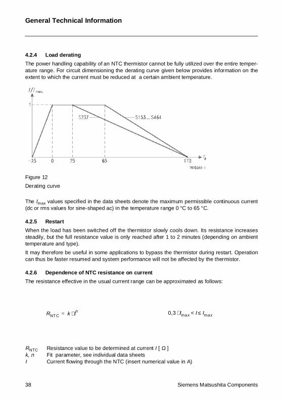
Figure 11 shows a typical example of an inrush protection circuit:
Figure 11
Mounting positions for NTC thermistors in a protective circuit
Selection of the most appropriate NTC thermistor is the precondition for effective circuit protection.The first and most important criterion is the maximum current during continuous operation, which isdetermined by the load. The rated resistance of the thermistor results from this current value.
4.2.3 Self-heating
The self-heating of a thermistor during operation depends on the load applied. Although some heatis being dissipated, the NTC thermistor may in extreme cases reach a mean temperature of up to250 °C. The dissipation factor δth specified in the data sheets has been measured in still air atTA = 25 °C on devices with clamp contacts. A change in the measuring conditions (e.g. stirred air =blower increases the dissipation factor ) will influence the dissipation factor.
The heat developed during operation will also be dissipated through the lead wires. When mountingNTC thermistors it should therefore be considered that the contact areas may become quite hot atmaximum load.
Load
Alternative mounting positions
Siemens Matsushita Components 37
General Technical Information
4.2.4 Load derating
The power handling capability of an NTC thermistor cannot be fully utilized over the entire temper-ature range. For circuit dimensioning the derating curve given below provides information on theextent to which the current must be reduced at a certain ambient temperature.
Figure 12
Derating curve
The Imax values specified in the data sheets denote the maximum permissible continuous current(dc or rms values for sine-shaped ac) in the temperature range 0 °C to 65 °C.
4.2.5 Restart
When the load has been switched off the thermistor slowly cools down. Its resistance increasessteadily, but the full resistance value is only reached after 1 to 2 minutes (depending on ambienttemperature and type).
It may therefore be useful in some applications to bypass the thermistor during restart. Operationcan thus be faster resumed and system performance will not be affected by the thermistor.
4.2.6 Dependence of NTC resistance on current
The resistance effective in the usual current range can be approximated as follows:
RNTC Resistance value to be determined at current I [ Ω ]k, n Fit parameter, see individual data sheetsI Current flowing through the NTC (insert numerical value in A)
RNT C k In⋅= 0,3 Imax⋅ I Imax≤<
38 Siemens Matsushita Components
General Technical Information
The calculated values only serve as an estimate for operation in still air at an ambient temperatureof 25 °C.
Note: With the equation above sufficiently accurate results are only obtained for the limited currentrange stated above.
4.2.7 Pulse strength
The currents during turn-on are much higher than the rated currents during continuous operation.To test the effects of these current surges S+M uses the following standard procedure:
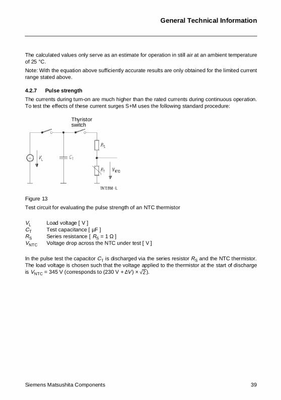
Figure 13
Test circuit for evaluating the pulse strength of an NTC thermistor
VL Load voltage [ V ]CT Test capacitance [ µF ]RS Series resistance [ RS = 1 Ω ]VNTC Voltage drop across the NTC under test [ V ]
In the pulse test the capacitor CT is discharged via the series resistor RS and the NTC thermistor.The load voltage is chosen such that the voltage applied to the thermistor at the start of dischargeis VNTC = 345 V (corresponds to (230 V + ∆V ) × ).
Thyristorswitch
√2
Siemens Matsushita Components 39
40
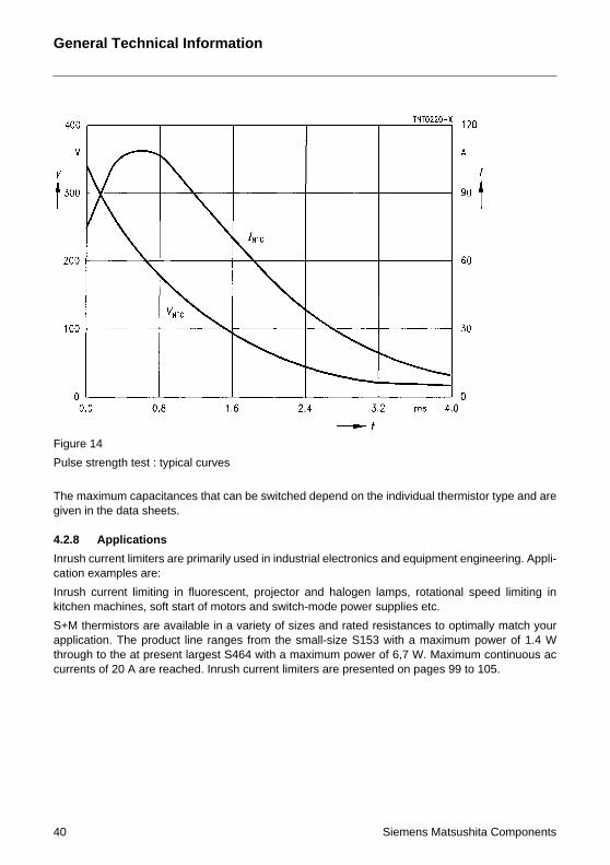
Figure 14
Pulse strength test : typ
The maximum capacitagiven in the data sheet
4.2.8 Applications
Inrush current limiters acation examples are:
Inrush current limitingkitchen machines, soft
S+M thermistors are aapplication. The produthrough to the at presecurrents of 20 A are re
General Technical
InformationSiemens Matsushita Components
ical curves
nces that can be switched depend on the individual thermistor type and ares.
re primarily used in industrial electronics and equipment engineering. Appli-
in fluorescent, projector and halogen lamps, rotational speed limiting instart of motors and switch-mode power supplies etc.
vailable in a variety of sizes and rated resistances to optimally match yourct line ranges from the small-size S153 with a maximum power of 1.4 Wnt largest S464 with a maximum power of 6,7 W. Maximum continuous acached. Inrush current limiters are presented on pages 99 to 105.
General Technical Information
4.3 Applications utilizing the influence of the disspation factor on the voltage/current characteristic
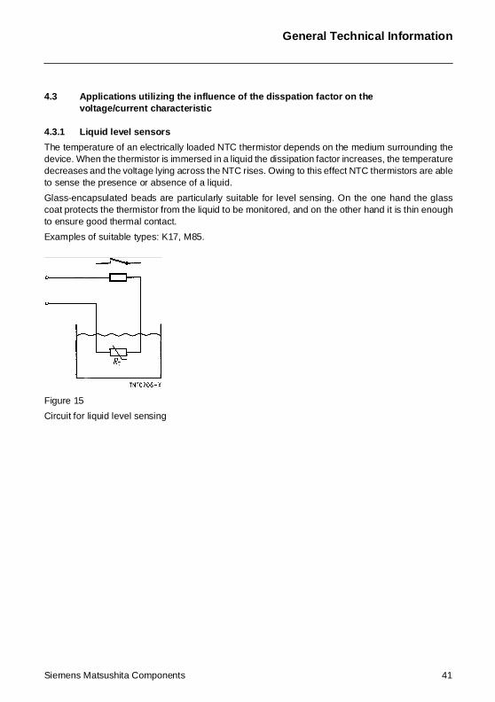
4.3.1 Liquid level sensors
The temperature of an electrically loaded NTC thermistor depends on the medium surrounding thedevice. When the thermistor is immersed in a liquid the dissipation factor increases, the temperaturedecreases and the voltage lying across the NTC rises. Owing to this effect NTC thermistors are ableto sense the presence or absence of a liquid.
Glass-encapsulated beads are particularly suitable for level sensing. On the one hand the glasscoat protects the thermistor from the liquid to be monitored, and on the other hand it is thin enoughto ensure good thermal contact.
Examples of suitable types: K17, M85.
Figure 15
Circuit for liquid level sensing
Siemens Matsushita Components 41
General Technical Information
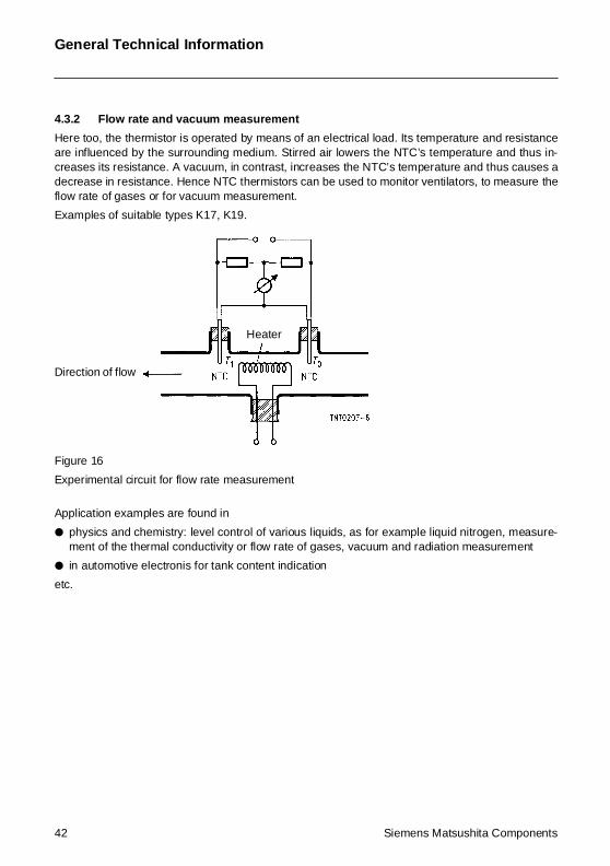
4.3.2 Flow rate and vacuum measurement
Here too, the thermistor is operated by means of an electrical load. Its temperature and resistanceare influenced by the surrounding medium. Stirred air lowers the NTC’s temperature and thus in-creases its resistance. A vacuum, in contrast, increases the NTC’s temperature and thus causes adecrease in resistance. Hence NTC thermistors can be used to monitor ventilators, to measure theflow rate of gases or for vacuum measurement.
Examples of suitable types K17, K19.
Figure 16
Experimental circuit for flow rate measurement
Application examples are found in
physics and chemistry: level control of various liquids, as for example liquid nitrogen, measure-ment of the thermal conductivity or flow rate of gases, vacuum and radiation measurement
in automotive electronis for tank content indication
etc.
Heater
Direction of flow
42 Siemens Matsushita Components
Siemens Matsushita C
4.4 Applications
If an NTC thermistor issured as a function of t
At first the thermistor isthe device. But this cursistance value of the thbecomes faster and fassistance the wattage wvalue. The entire watta
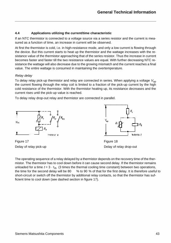
Relay delay
To delay relay pick-up the current flowing throcold resistance of the tcurrent rises until the p
To delay relay drop-ou
The operating sequencmistor. The thermistor unloaded for a time t =the time for the secondshort-circuit or switch oficient time to cool dow
Figure 17
Delay of relay pick-up
utilizing the current/time characteristic
connected to a voltage source via a series resistor and the current is mea-ime, an increase in current will be observed.
cold, i.e. in high-resistance mode, and only a low current is flowing throughrent starts to heat up the thermistor and the wattage increases with the re-ermistor approaching that of the series resistor. Thus the increase in currentter till the two resistance values are equal. With further decreasing NTC re-
ill also decrease due to the growing mismatch and the current reaches a finalge is consumed in maintaining the overtemperature.
thermistor and relay are connected in series. When applying a voltage Vopugh the relay coil is limited to a fraction of the pick-up current by the highhermistor. With the thermistor heating up, its resistance decreases and theick-up value is reached.
t relay and thermistor are connected in parallel.
General Technical Information
omponents 43
e of a relay delayed by a thermistor depends on the recovery time of the ther-has to cool down before it can cause second delay. If the thermistor remains 3 · τth (3 times the thermal cooling time constant) between two operations, delay will be 80 % to 90 % of that for the first delay. It is therefore useful toff the thermistor by additional relay contacts, so that the thermistor has suf-n (see dashed section in figure 17).
Figure 18
Delay of relay drop-out

Siemens Matsushita ComponentsCOMPONENTS
+S M
SCS – dependable, fast and competent
EMI suppression capacitors
Play it safe
Whether video recorder, television,refrigerator or toaster – our EMI sup-pression capacitors do a grand job inevery possible kind of entertainmentand consumer electronics appliance.They’ve also proven their worth inswitch-mode power supplies for PCs.No wonder, because the advantagesof film technology are there to beseen: low cost, no risk of failurethrough damp, and optimum self-
healing capability. The result – lessdestruction of equipment and ensuingfires. Plus the line is safeguardedagainst surges. In this way our ca-pacitors satisfy the user’s need forsafety, and the new EMC standardstoo of course.
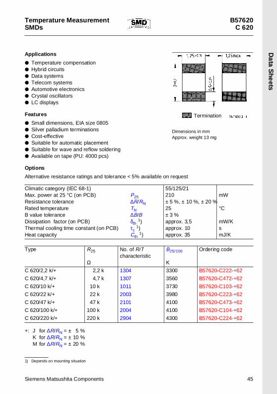
Temperature MeasurementSMDs
B57620C 620
Da
ta S
he
ets
App lications
Temperature compensation Hybrid circuits Data systems Telecom systems Automotive electronics Crystal oscillators LC displays
Features
Small dimensions, EIA size 0805 Silver palladium terminations Cost-effective Suitable for automatic placement Suitable for wave and reflow soldering Available on tape (PU: 4000 pcs)
Options
Alternative resistance ratings and tolerance < 5% available on request
+: J for ∆R/RN = ± 5 %K for ∆R/RN = ± 10 %M for ∆R/RN = ± 20 %
1) Depends on mounting situation
Climatic category (IEC 68-1)Max. power at 25 °C (on PCB) P25Resistance tolerance ∆R/RNRated temperature TNB value tolerance ∆B/BDissipation factor (on PCB) δth 1)Thermal cooling time constant (on PCB) τc
1)Heat capacity Cth 1)
55/125/21210± 5 %, ± 10 %, ± 20 %25± 3 %approx. 3,5approx. 10approx. 35
mW
°C
mW/KsmJ/K
Type R25
Ω
No. of R/T characteristic
B25/100
K
Ordering code
C 620/2,2 k/+ 2,2 k 1304 3300 B57620-C222-+62
C 620/4,7 k/+ 4,7 k 1307 3560 B57620-C472-+62
C 620/10 k/+ 10 k 1011 3730 B57620-C103-+62
C 620/22 k/+ 22 k 2003 3980 B57620-C223-+62
C 620/47 k/+ 47 k 2101 4100 B57620-C473-+62
C 620/100 k/+ 100 k 2004 4100 B57620-C104-+62
C 620/220 k/+ 220 k 2904 4300 B57620-C224-+62
Termination
Dimensions in mmApprox. weight 13 mg
Siemens Matsushita Components 45
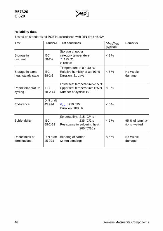
B57620C 620
Reliability data
Tested on standardized PCB in accordance with DIN draft 45 924
Test Standard Test conditions ∆R25/R25(typical)
Remarks
Storage indry heat
IEC68-2-2
Storage at uppercategory temperatureT: 125 °Ct: 1000 h
< 3 %
Storage in dampheat, steady state
IEC68-2-3
Temperature of air: 40 °CRelative humidity of air: 93 %Duration: 21 days
< 3 % No visibledamage
Rapid temperaturecycling
IEC68-2-14
Lower test temperature:– 55 °CUpper test temperature: 125 °CNumber of cycles: 10
< 3 %
EnduranceDIN draft45 924 Pmax: 210 mW
Duration: 1000 h< 5 %
Solderability IEC68-2-58
Solderability: 215 °C/4 s235 °C/2 s
Resistance to soldering heat:260 °C/10 s
< 5 % 95 % of termina-tions wetted
Robustness ofterminations
DIN draft45 924
Bending of carrier(2 mm bending)
< 5 % No visibledamage
46 Siemens Matsushita Components
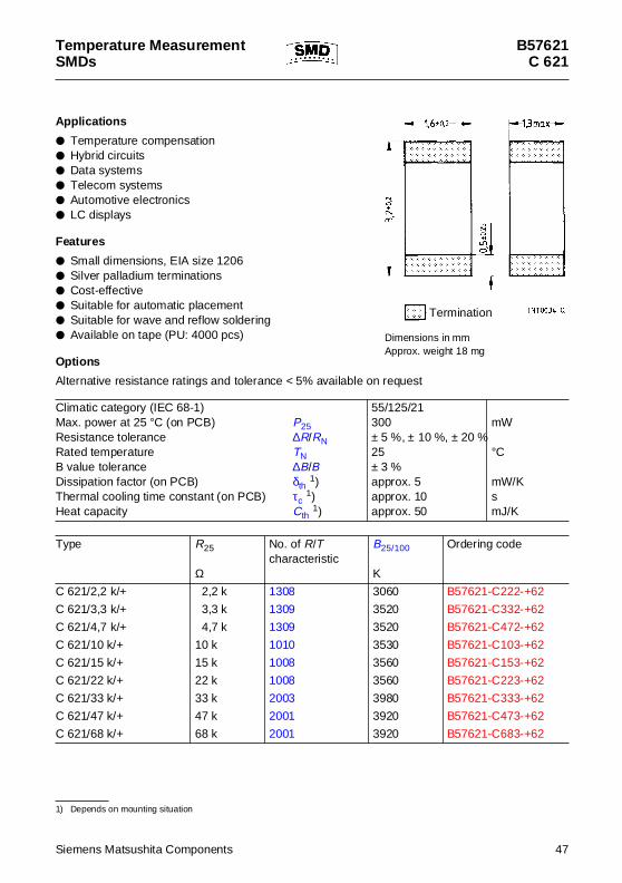
Temperature MeasurementSMDs
B57621C 621
App lications
Temperature compensation Hybrid circuits Data systems Telecom systems Automotive electronics LC displays
Features
Small dimensions, EIA size 1206 Silver palladium terminations Cost-effective Suitable for automatic placement Suitable for wave and reflow soldering Available on tape (PU: 4000 pcs)
Options
Alternative resistance ratings and tolerance < 5% available on request
1) Depends on mounting situation
Climatic category (IEC 68-1)Max. power at 25 °C (on PCB) P25Resistance tolerance ∆R/RNRated temperature TNB value tolerance ∆B/BDissipation factor (on PCB) δth 1)Thermal cooling time constant (on PCB) τc
1)Heat capacity Cth 1)
55/125/21300± 5 %, ± 10 %, ± 20 %25± 3 %approx. 5approx. 10approx. 50
mW
°C
mW/KsmJ/K
Type R25
Ω
No. of R/Tcharacteristic
B25/100
K
Ordering code
C 621/2,2 k/+ 2,2 k 1308 3060 B57621-C222-+62
C 621/3,3 k/+ 3,3 k 1309 3520 B57621-C332-+62
C 621/4,7 k/+ 4,7 k 1309 3520 B57621-C472-+62
C 621/10 k/+ 10 k 1010 3530 B57621-C103-+62
C 621/15 k/+ 15 k 1008 3560 B57621-C153-+62
C 621/22 k/+ 22 k 1008 3560 B57621-C223-+62
C 621/33 k/+ 33 k 2003 3980 B57621-C333-+62
C 621/47 k/+ 47 k 2001 3920 B57621-C473-+62
C 621/68 k/+ 68 k 2001 3920 B57621-C683-+62
Termination
Dimensions in mmApprox. weight 18 mg
Siemens Matsushita Components 47
B57621C 621
+: J for ∆R/RN = ± 5 %K for ∆R/RN = ± 10 %M for ∆R/RN = ± 20 %
Type R25
Ω
No. of R/Tcharacteristic
B25/100
K
Ordering code
C 621/100 k/+ 100 k 4901 3950 B57621-C104-+62
C 621/150 k/+ 150 k 2004 4100 B57621-C154-+62
C 621/220 k/+ 220 k 2903 4200 B57621-C224-+62
C 621/330 k/+ 330 k 1014 4250 B57621-C334-+62
C 621/470 k/+ 470 k 1014 4250 B57621-C474-+62
C 621/680 k/+ 680 k 4002 4250 B57621-C684-+62
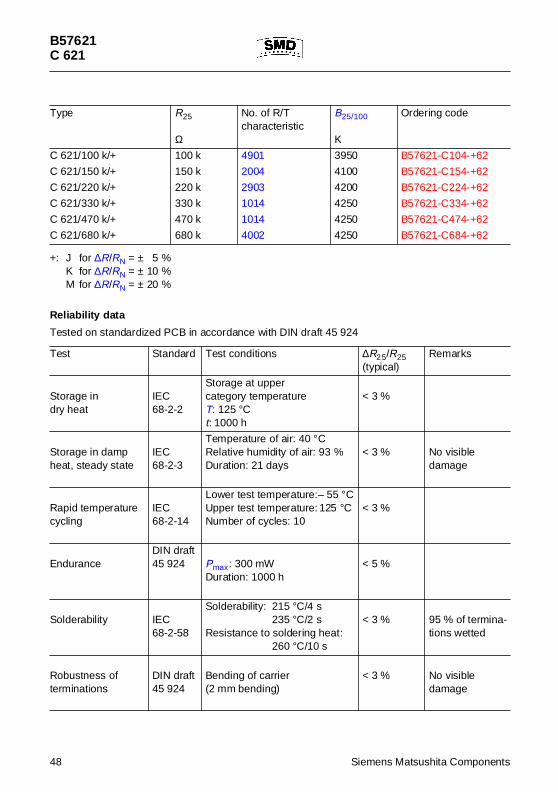
Reliabil ity data
Tested on standardized PCB in accordance with DIN draft 45 924
Test Standard Test conditions ∆R25/R25(typical)
Remarks
Storage indry heat
IEC68-2-2
Storage at uppercategory temperatureT: 125 °Ct: 1000 h
< 3 %
Storage in dampheat, steady state
IEC68-2-3
Temperature of air: 40 °CRelative humidity of air: 93 %Duration: 21 days
< 3 % No visibledamage
Rapid temperaturecycling
IEC68-2-14
Lower test temperature:– 55 °CUpper test temperature: 125 °CNumber of cycles: 10
< 3 %
EnduranceDIN draft45 924 Pmax: 300 mW
Duration: 1000 h< 5 %
Solderability IEC68-2-58
Solderability: 215 °C/4 s235 °C/2 s
Resistance to soldering heat:260 °C/10 s
< 3 % 95 % of termina-tions wetted
Robustness ofterminations
DIN draft45 924
Bending of carrier(2 mm bending)
< 3 % No visibledamage
48 Siemens Matsushita Components
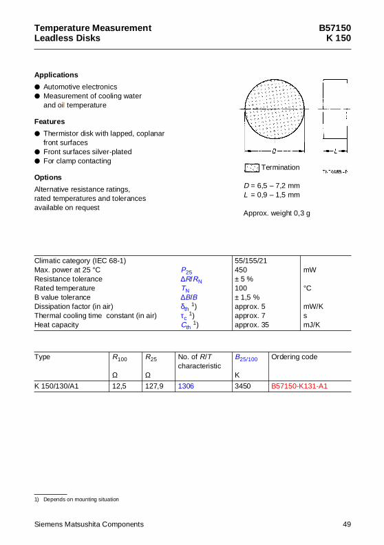
Temperature MeasurementLeadless Disks
B57150K 150
App lications
Automotive electronics Measurement of cooling water
and oil temperature
Features
Thermistor disk with lapped, coplanarfront surfaces
Front surfaces silver-plated For clamp contacting
Options
Alternative resistance ratings,rated temperatures and tolerancesavailable on request
1) Depends on mounting situation
Climatic category (IEC 68-1)Max. power at 25 °C P25Resistance tolerance ∆R/RNRated temperature TNB value tolerance ∆B/BDissipation factor (in air) δth 1)Thermal cooling time constant (in air) τc
1)Heat capacity Cth 1)
55/155/21450± 5 %100± 1,5 %approx. 5approx. 7approx. 35
mW
°C
mW/KsmJ/K
Type R100
Ω
R25
Ω
No. of R/Tcharacteristic
B25/100
K
Ordering code
K 150/130/A1 12,5 127,9 1306 3450 B57150-K131-A1
D = 6,5 – 7,2 mmL = 0,9 – 1,5 mm
Approx. weight 0,3 g
Termination
Siemens Matsushita Components 49
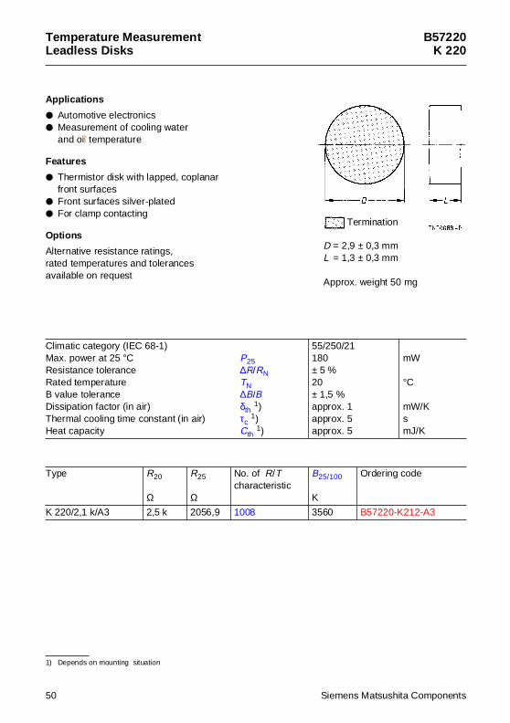
Temperature MeasurementLeadless Disks
B57220K 220
App lications
Automotive electronics Measurement of cooling water
and oil temperature
Features
Thermistor disk with lapped, coplanarfront surfaces
Front surfaces silver-plated For clamp contacting
Options
Alternative resistance ratings,rated temperatures and tolerancesavailable on request
1) Depends on mounting situation
Climatic category (IEC 68-1)Max. power at 25 °C P25Resistance tolerance ∆R/RNRated temperature TNB value tolerance ∆B/BDissipation factor (in air) δth 1)Thermal cooling time constant (in air) τc
1)Heat capacity Cth 1)
55/250/21180± 5 %20± 1,5 %approx. 1approx. 5approx. 5
mW
°C
mW/KsmJ/K
Type R20
Ω
R25
Ω
No. of R/Tcharacteristic
B25/100
K
Ordering code
K 220/2,1 k/A3 2,5 k 2056,9 1008 3560 B57220-K212-A3
D = 2,9 ± 0,3 mmL = 1,3 ± 0,3 mm
Approx. weight 50 mg
Termination
50 Siemens Matsushita Components
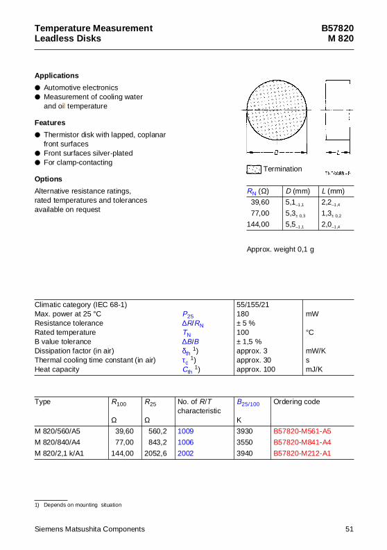
Temperature MeasurementLeadless Disks
B57820M 820
App lications
Automotive electronics Measurement of cooling water
and oil temperature
Features
Thermistor disk with lapped, coplanarfront surfaces
Front surfaces silver-plated For clamp-contacting
Options
Alternative resistance ratings,rated temperatures and tolerancesavailable on request
1) Depends on mounting situation
Climatic category (IEC 68-1)Max. power at 25 °C P25Resistance tolerance ∆R/RNRated temperature TNB value tolerance ∆B/BDissipation factor (in air) δth 1)Thermal cooling time constant (in air) τc
1)Heat capacity Cth 1)
55/155/21180± 5 %100± 1,5 %approx. 3approx. 30approx. 100
mW
°C
mW/KsmJ/K
Type R100
Ω
R25
Ω
No. of R/Tcharacteristic
B25/100
K
Ordering code
M 820/560/A5 39,60 560,2 1009 3930 B57820-M561-A5
M 820/840/A4 77,00 843,2 1006 3550 B57820-M841-A4
M 820/2,1 k/A1 144,00 2052,6 2002 3940 B57820-M212-A1
Approx. weight 0,1 g
RN (Ω) D (mm) L (mm)
39,60 5,1–1,1 2,2–1,4
77,00 5,3± 0,3 1,3± 0,2
144,00 5,5–1,1 2,0–1,4
Termination
Siemens Matsushita Components 51
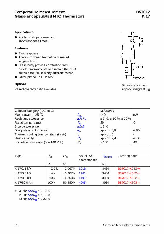
Temperature MeasurementGlass-Encapsu lated NTC Thermistors
B57017K 17
App lications
For high temperatures and short response times
Features
Fast response Thermistor bead hermetically sealed
in glass body Glass body provides protection from
hostile environments and makes the NTCsuitable for use in many different media
Silver-plated Fe/Ni leads
Options
Paired characteristic available
+: J for ∆R/RN = ± 5 %K for ∆R/RN = ± 10 %M for ∆R/RN = ± 20 %
Climatic category (IEC 68-1)Max. power at 25 °C P25Resistance tolerance ∆R/RNRated temperature TNB value tolerance ∆B/BDissipation factor (in air) δthThermal cooling time constant (in air) τcHeat capacity CthInsulation resistance (V = 100 Vdc) Ris
55/250/56140± 5 %, ± 10 %, ± 20 %20± 3 %approx. 0,8approx. 3approx. 2,4> 100
mW
°C
mW/KsmJ/KMΩ
Type R20
Ω
R25
Ω
No. of R/Tcharacteristic
B25/100
K
Ordering code
K 17/2,1 k/+ 2,5 k 2,067 k 1018 3430 B57017-K212-+
K 17/3,3 k/+ 4 k 3,307 k 1101 3430 B57017-K332-+
K 17/8,2 k/+ 10 k 8,268 k 1101 3430 B57017-K822-+
K 17/80,0 k/+ 100 k 80,380 k 4005 3950 B57017-K803-+
Dimensions in mmApprox. weight 0,3 g
52 Siemens Matsushita Components
Temperature MeasurementGlass-Encapsu lated NTC Thermistors
B57019K 19
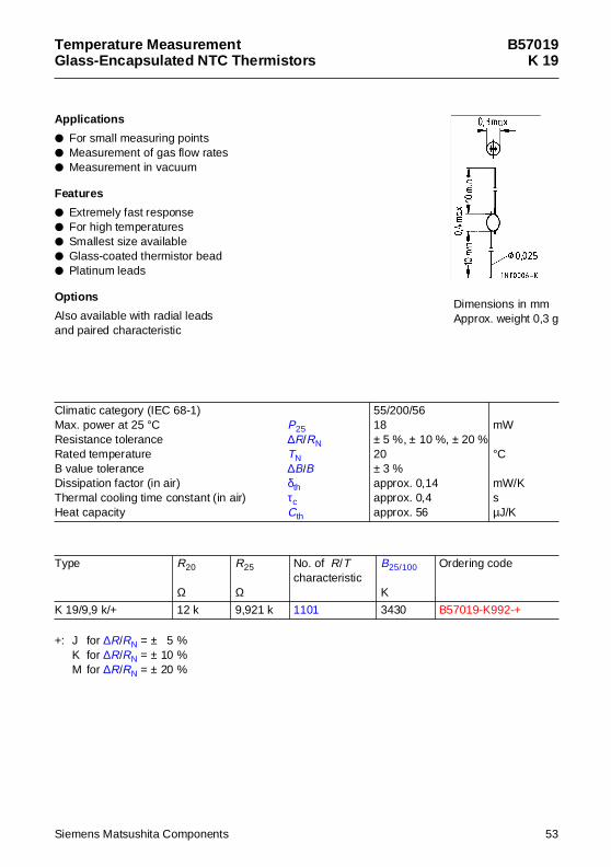
App lications
For small measuring points Measurement of gas flow rates Measurement in vacuum
Features
Extremely fast response For high temperatures Smallest size available Glass-coated thermistor bead Platinum leads
Options
Also available with radial leadsand paired characteristic
+: J for ∆R/RN = ± 5 %K for ∆R/RN = ± 10 %M for ∆R/RN = ± 20 %
Climatic category (IEC 68-1)Max. power at 25 °C P25Resistance tolerance ∆R/RNRated temperature TNB value tolerance ∆B/BDissipation factor (in air) δthThermal cooling time constant (in air) τcHeat capacity Cth
55/200/5618± 5 %, ± 10 %, ± 20 %20± 3 %approx. 0,14approx. 0,4approx. 56
mW
°C
mW/KsµJ/K
Type R20
Ω
R25
Ω
No. of R/Tcharacteristic
B25/100
K
Ordering code
K 19/9,9 k/+ 12 k 9,921 k 1101 3430 B57019-K992-+
Dimensions in mmApprox. weight 0,3 g
Siemens Matsushita Components 53
Temperature MeasurementGlass-Encapsu lated NTC Thermistors
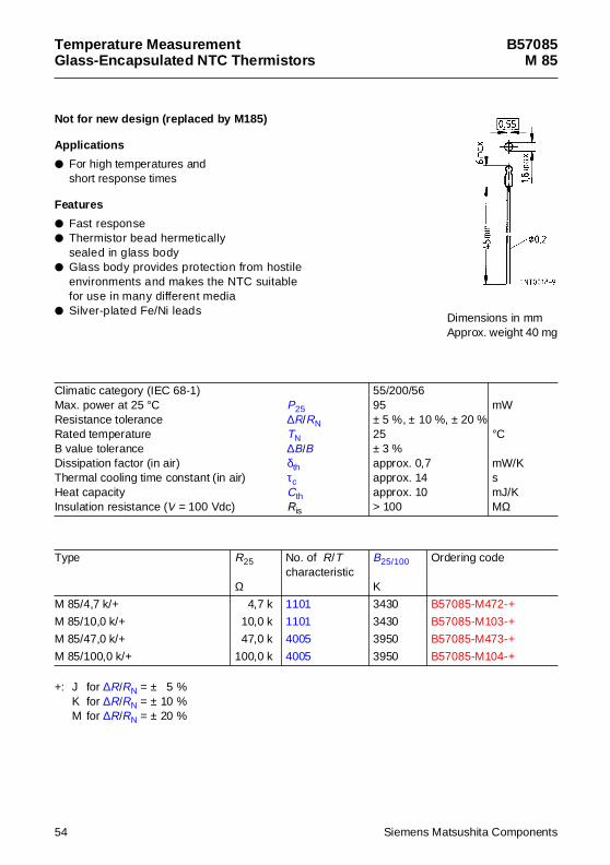
B57085M 85
Not for new des ign (replaced by M185)
App lications
For high temperatures and short response times
Features
Fast response Thermistor bead hermetically
sealed in glass body Glass body provides protection from hostile
environments and makes the NTC suitablefor use in many different media
Silver-plated Fe/Ni leads
+: J for ∆R/RN = ± 5 %K for ∆R/RN = ± 10 %M for ∆R/RN = ± 20 %
Climatic category (IEC 68-1)Max. power at 25 °C P25Resistance tolerance ∆R/RNRated temperature TNB value tolerance ∆B/BDissipation factor (in air) δthThermal cooling time constant (in air) τcHeat capacity CthInsulation resistance (V = 100 Vdc) Ris
55/200/5695± 5 %, ± 10 %, ± 20 %25± 3 %approx. 0,7approx. 14approx. 10> 100
mW
°C
mW/KsmJ/KMΩ
Type R25
Ω
No. of R/Tcharacteristic
B25/100
K
Ordering code
M 85/4,7 k/+ 4,7 k 1101 3430 B57085-M472-+
M 85/10,0 k/+ 10,0 k 1101 3430 B57085-M103-+
M 85/47,0 k/+ 47,0 k 4005 3950 B57085-M473-+
M 85/100,0 k/+ 100,0 k 4005 3950 B57085-M104-+
Dimensions in mmApprox. weight 40 mg
54 Siemens Matsushita Components
Temperature MeasurementGlass-Encapsu lated NTC Thermistors
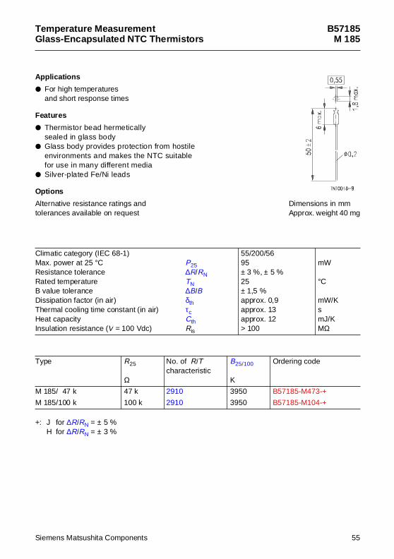
B57185M 185
App lications
For high temperatures and short response times
Features
Thermistor bead hermeticallysealed in glass body
Glass body provides protection from hostileenvironments and makes the NTC suitablefor use in many different media
Silver-plated Fe/Ni leads
Options
Alternative resistance ratings andtolerances available on request
+: J for ∆R/RN = ± 5 %H for ∆R/RN = ± 3 %
Climatic category (IEC 68-1)Max. power at 25 °C P25Resistance tolerance ∆R/RNRated temperature TNB value tolerance ∆B/BDissipation factor (in air) δthThermal cooling time constant (in air) τcHeat capacity CthInsulation resistance (V = 100 Vdc) Ris
55/200/5695± 3 %, ± 5 %25± 1,5 %approx. 0,9approx. 13approx. 12> 100
mW
°C
mW/KsmJ/KMΩ
Type R25
Ω
No. of R/Tcharacteristic
B25/100
K
Ordering code
M 185/ 47 k 47 k 2910 3950 B57185-M473-+
M 185/100 k 100 k 2910 3950 B57185-M104-+
Dimensions in mmApprox. weight 40 mg
Siemens Matsushita Components 55
Temperature MeasurementGlass-Encapsu lated NTC Thermistors
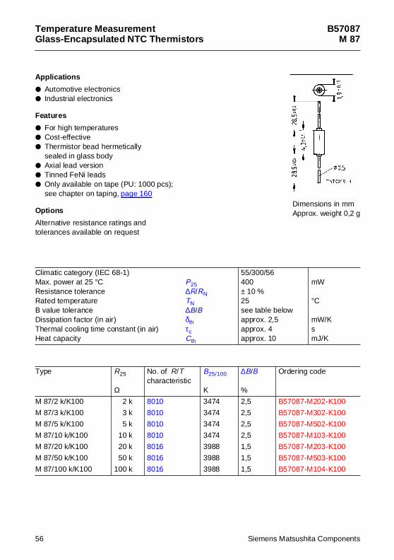
B57087M 87
App lications
Automotive electronics Industrial electronics
Features
For high temperatures Cost-effective Thermistor bead hermetically
sealed in glass body Axial lead version Tinned FeNi leads Only available on tape (PU: 1000 pcs);
see chapter on taping, page 160
Options
Alternative resistance ratings andtolerances available on request
Climatic category (IEC 68-1)Max. power at 25 °C P25Resistance tolerance ∆R/RNRated temperature TNB value tolerance ∆B/BDissipation factor (in air) δthThermal cooling time constant (in air) τcHeat capacity Cth
55/300/56400± 10 %25see table belowapprox. 2,5approx. 4approx. 10
mW
°C
mW/KsmJ/K
Type R25
Ω
No. of R/Tcharacteristic
B25/100
K
∆B/B
%
Ordering code
M 87/2 k/K100 2 k 8010 3474 2,5 B57087-M202-K100
M 87/3 k/K100 3 k 8010 3474 2,5 B57087-M302-K100
M 87/5 k/K100 5 k 8010 3474 2,5 B57087-M502-K100
M 87/10 k/K100 10 k 8010 3474 2,5 B57087-M103-K100
M 87/20 k/K100 20 k 8016 3988 1,5 B57087-M203-K100
M 87/50 k/K100 50 k 8016 3988 1,5 B57087-M503-K100
M 87/100 k/K100 100 k 8016 3988 1,5 B57087-M104-K100
Dimensions in mmApprox. weight 0,2 g
56 Siemens Matsushita Components
Temperature MeasurementLeaded Disks
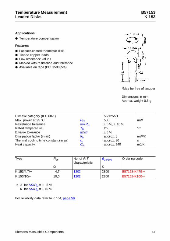
B57153K 153
App lications
Temperature compensation
Features
Lacquer-coated thermistor disk Tinned copper leads Low resistance values Marked with resistance and tolerance Available on tape (PU: 1500 pcs)
+: J for ∆R/RN = ± 5 %K for ∆R/RN = ± 10 %
For reliability data refer to K 164, page 59.
Climatic category (IEC 68-1)Max. power at 25 °C P25Resistance tolerance ∆R/RNRated temperature TNB value tolerance ∆B/BDissipation factor (in air) δthThermal cooling time constant (in air) τcHeat capacity Cth
55/125/21500± 5 %, ± 10 %25± 3 %approx. 8approx. 30approx. 240
mW
°C
mW/KsmJ/K
Type R25
Ω
No. of R/Tcharacteristic
B25/100
K
Ordering code
K 153/4,7/+ 4,7 1202 2800 B57153-K479-+
K 153/10/+ 10,0 1202 2800 B57153-K100-+
*May be free of lacquer
Dimensions in mmApprox. weight 0,6 g
Siemens Matsushita Components 57
Temperature MeasurementLeaded Disks
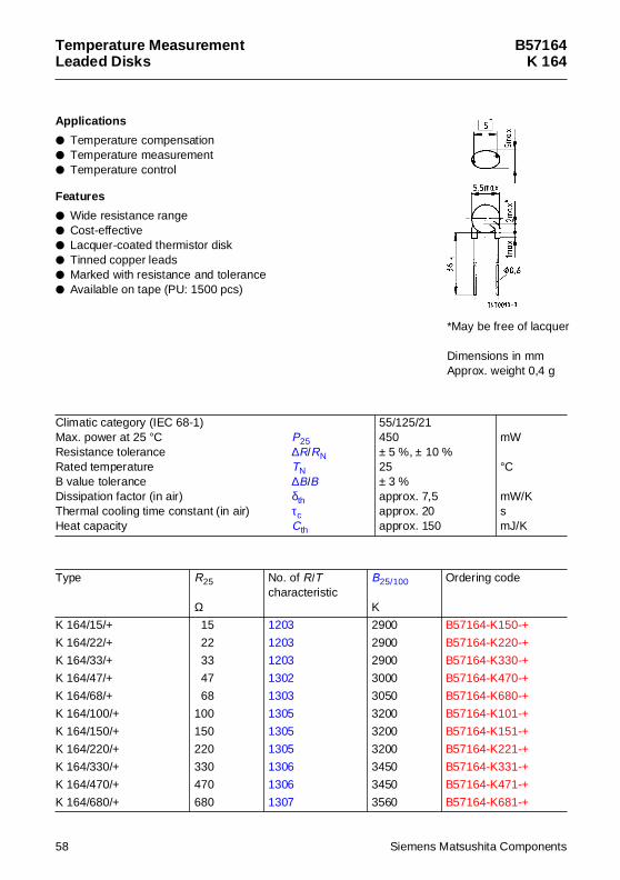
B57164K 164
App lications
Temperature compensation Temperature measurement Temperature control
Features
Wide resistance range Cost-effective Lacquer-coated thermistor disk Tinned copper leads Marked with resistance and tolerance Available on tape (PU: 1500 pcs)
Climatic category (IEC 68-1)Max. power at 25 °C P25Resistance tolerance ∆R/RNRated temperature TNB value tolerance ∆B/BDissipation factor (in air) δthThermal cooling time constant (in air) τcHeat capacity Cth
55/125/21450± 5 %, ± 10 %25± 3 %approx. 7,5approx. 20approx. 150
mW
°C
mW/KsmJ/K
Type R25
Ω
No. of R/Tcharacteristic
B25/100
K
Ordering code
K 164/15/+ 15 1203 2900 B57164-K150-+
K 164/22/+ 22 1203 2900 B57164-K220-+
K 164/33/+ 33 1203 2900 B57164-K330-+
K 164/47/+ 47 1302 3000 B57164-K470-+
K 164/68/+ 68 1303 3050 B57164-K680-+
K 164/100/+ 100 1305 3200 B57164-K101-+
K 164/150/+ 150 1305 3200 B57164-K151-+
K 164/220/+ 220 1305 3200 B57164-K221-+
K 164/330/+ 330 1306 3450 B57164-K331-+
K 164/470/+ 470 1306 3450 B57164-K471-+
K 164/680/+ 680 1307 3560 B57164-K681-+
*May be free of lacquer
Dimensions in mmApprox. weight 0,4 g
58 Siemens Matsushita Components
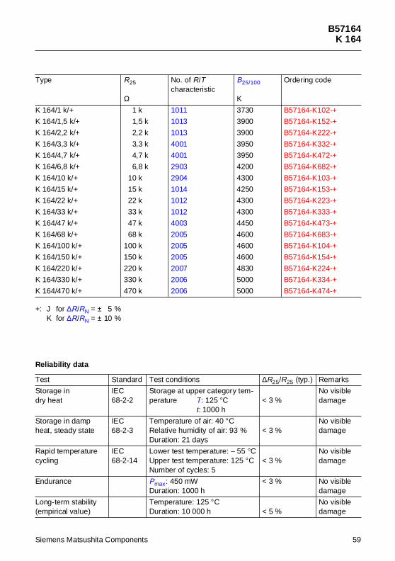
B57164K 164
+: J for ∆R/RN = ± 5 %K for ∆R/RN = ± 10 %
K 164/1 k/+ 1 k 1011 3730 B57164-K102-+
K 164/1,5 k/+ 1,5 k 1013 3900 B57164-K152-+
K 164/2,2 k/+ 2,2 k 1013 3900 B57164-K222-+
K 164/3,3 k/+ 3,3 k 4001 3950 B57164-K332-+
K 164/4,7 k/+ 4,7 k 4001 3950 B57164-K472-+
K 164/6,8 k/+ 6,8 k 2903 4200 B57164-K682-+
K 164/10 k/+ 10 k 2904 4300 B57164-K103-+
K 164/15 k/+ 15 k 1014 4250 B57164-K153-+
K 164/22 k/+ 22 k 1012 4300 B57164-K223-+
K 164/33 k/+ 33 k 1012 4300 B57164-K333-+
K 164/47 k/+ 47 k 4003 4450 B57164-K473-+
K 164/68 k/+ 68 k 2005 4600 B57164-K683-+
K 164/100 k/+ 100 k 2005 4600 B57164-K104-+
K 164/150 k/+ 150 k 2005 4600 B57164-K154-+
K 164/220 k/+ 220 k 2007 4830 B57164-K224-+
K 164/330 k/+ 330 k 2006 5000 B57164-K334-+
K 164/470 k/+ 470 k 2006 5000 B57164-K474-+
Reliabil ity data
Test Standard Test conditions ∆R25/R25 (typ.) Remarks
Storage indry heat
IEC68-2-2
Storage at upper category tem-perature T: 125 °C
t: 1000 h< 3 %
No visibledamage
Storage in dampheat, steady state
IEC68-2-3
Temperature of air: 40 °CRelative humidity of air: 93 %Duration: 21 days
< 3 %No visibledamage
Rapid temperaturecycling
IEC68-2-14
Lower test temperature: – 55 °CUpper test temperature: 125 °CNumber of cycles: 5
< 3 %No visibledamage
Endurance Pmax: 450 mWDuration: 1000 h
< 3 % No visibledamage
Long-term stability(empirical value)
Temperature: 125 °CDuration: 10 000 h < 5 %
No visibledamage
Type R25
Ω
No. of R/Tcharacteristic
B25/100
K
Ordering code
Siemens Matsushita Components 59
Temperature MeasurementLeaded Disks
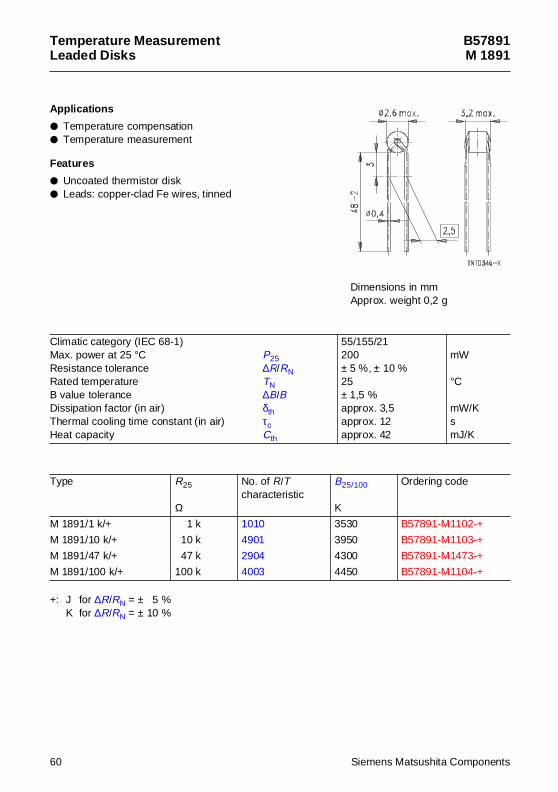
B57891M 1891
App lications
Temperature compensation Temperature measurement
Features
Uncoated thermistor disk Leads: copper-clad Fe wires, tinned
+: J for ∆R/RN = ± 5 %K for ∆R/RN = ± 10 %
Climatic category (IEC 68-1)Max. power at 25 °C P25Resistance tolerance ∆R/RNRated temperature TNB value tolerance ∆B/BDissipation factor (in air) δthThermal cooling time constant (in air) τcHeat capacity Cth
55/155/21200± 5 %, ± 10 %25± 1,5 %approx. 3,5approx. 12approx. 42
mW
°C
mW/KsmJ/K
Type R25
Ω
No. of R/Tcharacteristic
B25/100
K
Ordering code
M 1891/1 k/+ 1 k 1010 3530 B57891-M1102-+
M 1891/10 k/+ 10 k 4901 3950 B57891-M1103-+
M 1891/47 k/+ 47 k 2904 4300 B57891-M1473-+
M 1891/100 k/+ 100 k 4003 4450 B57891-M1104-+
Dimensions in mmApprox. weight 0,2 g
60 Siemens Matsushita Components
Temperature MeasurementLeaded Disks
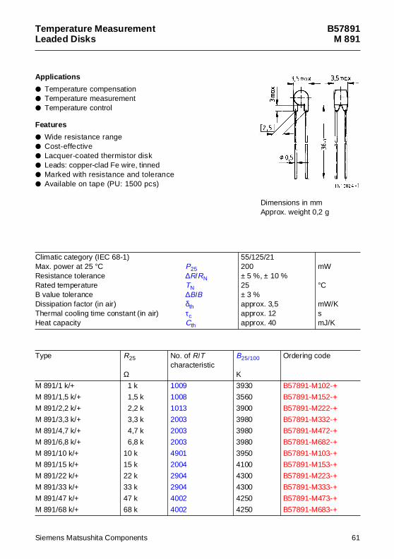
B57891M 891
App lications
Temperature compensation Temperature measurement Temperature control
Features
Wide resistance range Cost-effective Lacquer-coated thermistor disk Leads: copper-clad Fe wire, tinned Marked with resistance and tolerance Available on tape (PU: 1500 pcs)
Climatic category (IEC 68-1)Max. power at 25 °C P25Resistance tolerance ∆R/RNRated temperature TNB value tolerance ∆B/BDissipation factor (in air) δthThermal cooling time constant (in air) τcHeat capacity Cth
55/125/21200± 5 %, ± 10 %25± 3 %approx. 3,5approx. 12approx. 40
mW
°C
mW/KsmJ/K
Type R25
Ω
No. of R/Tcharacteristic
B25/100
K
Ordering code
M 891/1 k/+ 1 k 1009 3930 B57891-M102-+
M 891/1,5 k/+ 1,5 k 1008 3560 B57891-M152-+
M 891/2,2 k/+ 2,2 k 1013 3900 B57891-M222-+
M 891/3,3 k/+ 3,3 k 2003 3980 B57891-M332-+
M 891/4,7 k/+ 4,7 k 2003 3980 B57891-M472-+
M 891/6,8 k/+ 6,8 k 2003 3980 B57891-M682-+
M 891/10 k/+ 10 k 4901 3950 B57891-M103-+
M 891/15 k/+ 15 k 2004 4100 B57891-M153-+
M 891/22 k/+ 22 k 2904 4300 B57891-M223-+
M 891/33 k/+ 33 k 2904 4300 B57891-M333-+
M 891/47 k/+ 47 k 4002 4250 B57891-M473-+
M 891/68 k/+ 68 k 4002 4250 B57891-M683-+
Dimensions in mmApprox. weight 0,2 g
Siemens Matsushita Components 61
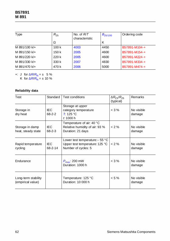
B57891M 891
+: J for ∆R/RN = ± 5 %K for ∆R/RN = ± 10 %
M 891/100 k/+ 100 k 4003 4450 B57891-M104-+
M 891/150 k/+ 150 k 2005 4600 B57891-M154-+
M 891/220 k/+ 220 k 2005 4600 B57891-M224-+
M 891/330 k/+ 330 k 2007 4830 B57891-M334-+
M 891/470 k/+ 470 k 2006 5000 B57891-M474-+
Reliabil ity data
Test Standard Test conditions ∆R25/R25(typical)
Remarks
Storage indry heat
IEC68-2-2
Storage at upper category temperatureT: 125 °Ct: 1000 h
< 3 % No visibledamage
Storage in dampheat, steady state
IEC68-2-3
Temperature of air: 40 °CRelative humidity of air: 93 %Duration: 21 days
< 2 % No visibledamage
Rapid temperaturecycling
IEC68-2-14
Lower test temperature:– 55 °CUpper test temperature: 125 °CNumber of cycles: 5
< 2 % No visibledamage
Endurance Pmax: 200 mWDuration: 1000 h
< 3 % No visibledamage
Long-term stability(empirical value)
Temperature: 125 °CDuration: 10 000 h
< 5 % No visibledamage
Type R25
Ω
No. of R/Tcharacteristic
B25/100
K
Ordering code
62 Siemens Matsushita Components
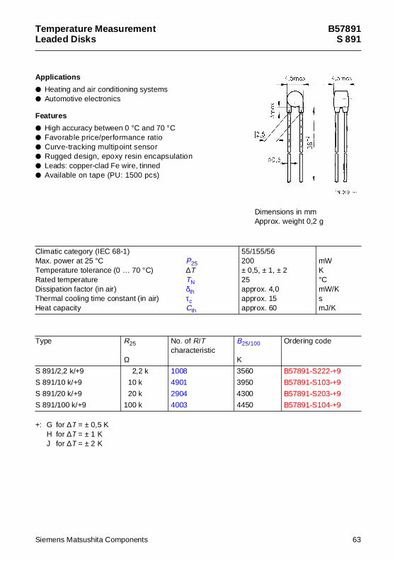
Temperature MeasurementLeaded Disks
B57891S 891
App lications
Heating and air conditioning systems Automotive electronics
Features
High accuracy between 0 °C and 70 °C Favorable price/performance ratio Curve-tracking multipoint sensor Rugged design, epoxy resin encapsulation Leads: copper-clad Fe wire, tinned Available on tape (PU: 1500 pcs)
+: G for ∆T = ± 0,5 KH for ∆T = ± 1 KJ for ∆T = ± 2 K
Climatic category (IEC 68-1)Max. power at 25 °C P25Temperature tolerance (0 … 70 °C) ∆TRated temperature TNDissipation factor (in air) δthThermal cooling time constant (in air) τcHeat capacity Cth
55/155/56200± 0,5, ± 1, ± 225approx. 4,0approx. 15approx. 60
mWK°CmW/KsmJ/K
Type R25
Ω
No. of R/Tcharacteristic
B25/100
K
Ordering code
S 891/2,2 k/+9 2,2 k 1008 3560 B57891-S222-+9
S 891/10 k/+9 10 k 4901 3950 B57891-S103-+9
S 891/20 k/+9 20 k 2904 4300 B57891-S203-+9
S 891/100 k/+9 100 k 4003 4450 B57891-S104-+9
Dimensions in mmApprox. weight 0,2 g
Siemens Matsushita Components 63
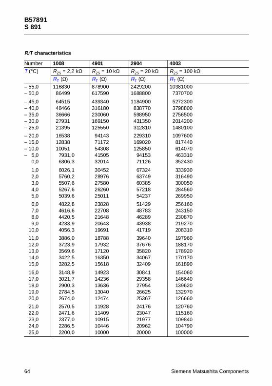
B57891S 891
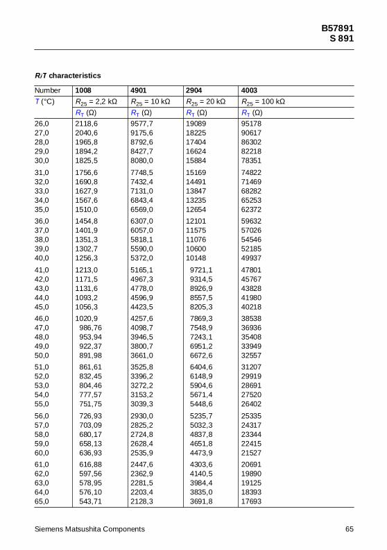
R/T characteristics
Number 1008 4901 2904 4003
T (°C) R25 = 2,2 kΩ R25 = 10 kΩ R25 = 20 kΩ R25 = 100 kΩRT (Ω) RT (Ω) RT (Ω) RT (Ω)
– 55,0– 50,0
– 45,0– 40,0– 35,0– 30,0– 25,0
– 20,0– 15,0– 10,0– 5,0– 0,0
– 1,0– 2,0– 3,0– 4,0– 5,0
– 6,0– 7,0– 8,0– 9,0– 10,0
– 11,0– 12,0– 13,0– 14,0– 15,0
– 16,0– 17,0– 18,0– 19,0– 20,0
– 21,0– 22,0– 23,0– 24,0– 25,0
11683086499
6451548466366662793121395
165381283810051
7931,06306,3
6026,15760,25507,65267,65039,6
4822,84616,64420,54233,94056,3
3886,03723,93569,63422,53282,5
3148,93021,72900,32784,52674,0
2570,52471,62377,02286,52200,0
878900617590
439340316180230060169150125550
9414371172543084150532014
3045228976275802626025011
2382822708216482064319691
1878817932171201635015618
1492314236136361304012474
1192811409109151044610000
24292001688800
1184900838770598950431350312810
229310169020125850
9415371126
6732463749603855721854237
5142948783462894393841719
3964037676358203406732409
3084129358279542662525367
2417623047219772096220000
103810007370700
52723003798800275650020142001480100
1097600817440614070463310352430
333930316490300050284560269950
256160243150230870219270208310
197960188170178920170170161890
154060146640139620132970126660
120760115160109840104790100000
64 Siemens Matsushita Components
B57891S 891
26,027,028,029,030,0
31,032,033,034,035,0
36,037,038,039,040,0
41,042,043,044,045,0
46,047,048,049,050,0
51,052,053,054,055,0
56,057,058,059,060,0
61,062,063,064,065,0
2118,62040,61965,81894,21825,5
1756,61690,81627,91567,61510,0
1454,81401,91351,31302,71256,3
1213,01171,51131,61093,21056,3
1020,9986,76953,94922,37891,98
861,61832,45804,46777,57751,75
726,93703,09680,17658,13636,93
616,88597,56578,95576,10543,71
9577,79175,68792,68427,78080,0
7748,57432,47131,06843,46569,0
6307,06057,05818,15590,05372,0
5165,14967,34778,04596,94423,5
4257,64098,73946,53800,73661,0
3525,83396,23272,23153,23039,3
2930,02825,22724,82628,42535,9
2447,62362,92281,52203,42128,3
1908918225174041662415884
1516914491138471323512654
1210111575110761060010148
9721,19314,58926,98557,58205,3
7869,37548,97243,16951,26672,6
6404,66148,95904,65671,45448,6
5235,75032,34837,84651,84473,9
4303,64140,53984,43835,03691,8
9517890617863028221878351
7482271469682826525362372
5963257026545465218549937
4780145767438284198040218
3853836936354083394932557
3120729919286912752026402
2533524317233442241521527
2069119890191251839317693
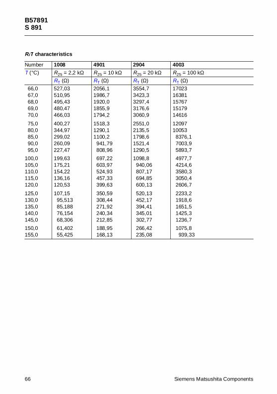
R/T characteristics
Number 1008 4901 2904 4003
T (°C) R25 = 2,2 kΩ R25 = 10 kΩ R25 = 20 kΩ R25 = 100 kΩRT (Ω) RT (Ω) RT (Ω) RT (Ω)
Siemens Matsushita Components 65
B57891S 891
66,067,068,069,070,0
75,080,085,090,095,0
100,0105,0110,0115,0120,0
125,0130,0135,0140,0145,0
150,0155,0
527,03510,95495,43480,47466,03
400,27344,97299,02260,09227,47
199,63175,21154,22136,16120,53
107,1595,51385,18876,15468,306
61,40255,425
2056,11986,71920,01855,91794,2
1518,31290,11100,2
941,79808,96
697,22603,97524,93457,33399,63
350,59308,44271,92240,34212,85
188,95168,13
3554,73423,33297,43176,63060,9
2551,02135,51798,61521,41290,5
1098,8940,06807,17694,85600,13
520,13452,17394,41345,01302,77
266,42235,08
1702316381157671517914616
1209710053
8376,17003,95893,7
4977,74214,63580,33050,42606,7
2233,21918,61651,51425,31236,7
1075,8939,33
R/T characteristics
Number 1008 4901 2904 4003
T (°C) R25 = 2,2 kΩ R25 = 10 kΩ R25 = 20 kΩ R25 = 100 kΩRT (Ω) RT (Ω) RT (Ω) RT (Ω)
66 Siemens Matsushita Components
Siemens Matsushita C
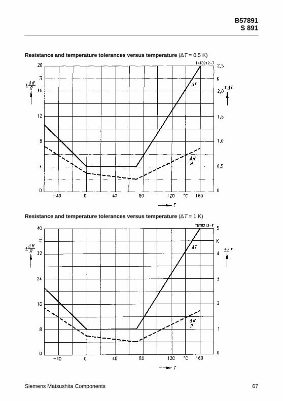
Resistance and tempe
Resistance and tempe
rature tolerances versus temperature (∆T = 0,5 K)
rature tolerances versus temperature (∆T = 1 K)
B57891S 891
omponents 67
68
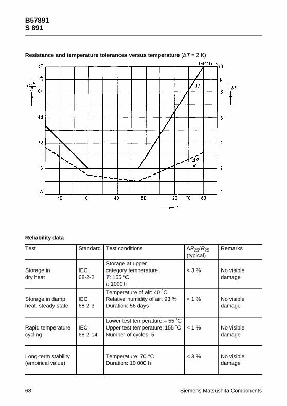
Resistance and tempe
Reliability data
Test S
Storage indry heat
I6
Storage in dampheat, steady state
I6
Rapid temperaturecycling
I6
Long-term stability(empirical value)
B57891S 891
rature tolerances versus temperature (∆T = 2 K)
Siemens Matsushita Components
tandard Test conditions ∆R25/R25(typical)
Remarks
EC8-2-2
Storage at uppercategory temperatureT: 155 °Ct: 1000 h
< 3 % No visibledamage
EC8-2-3
Temperature of air: 40 ˚CRelative humidity of air: 93 %Duration: 56 days
< 1 % No visibledamage
EC8-2-14
Lower test temperature:– 55 ˚CUpper test temperature: 155 ˚CNumber of cycles: 5
< 1 % No visibledamage
Temperature: 70 °CDuration: 10 000 h
< 3 % No visibledamage
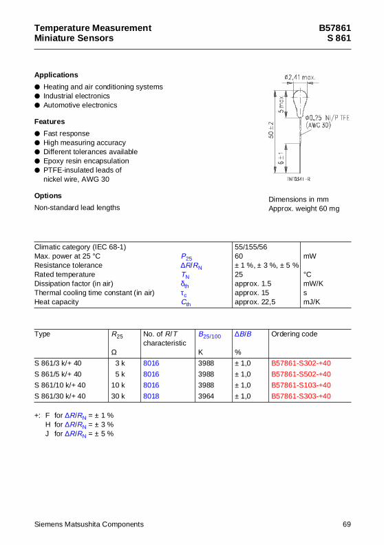
Temperature MeasurementMiniature Senso rs
B57861S 861
App lications
Heating and air conditioning systems Industrial electronics Automotive electronics
Features
Fast response High measuring accuracy Different tolerances available Epoxy resin encapsulation PTFE-insulated leads of
nickel wire, AWG 30
Options
Non-standard lead lengths
+: F for ∆R/RN = ± 1 %H for ∆R/RN = ± 3 %J for ∆R/RN = ± 5 %
Climatic category (IEC 68-1)Max. power at 25 °C P25Resistance tolerance ∆R/RNRated temperature TNDissipation factor (in air) δthThermal cooling time constant (in air) τcHeat capacity Cth
55/155/5660± 1 %, ± 3 %, ± 5 %25approx. 1.5approx. 15approx. 22,5
mW
°CmW/KsmJ/K
Type R25
Ω
No. of R/Tcharacteristic
B25/100
K
∆B/B
%
Ordering code
S 861/3 k/+ 40 3 k 8016 3988 ± 1,0 B57861-S302-+40
S 861/5 k/+ 40 5 k 8016 3988 ± 1,0 B57861-S502-+40
S 861/10 k/+ 40 10 k 8016 3988 ± 1,0 B57861-S103-+40
S 861/30 k/+ 40 30 k 8018 3964 ± 1,0 B57861-S303-+40
Dimensions in mmApprox. weight 60 mg
Siemens Matsushita Components 69
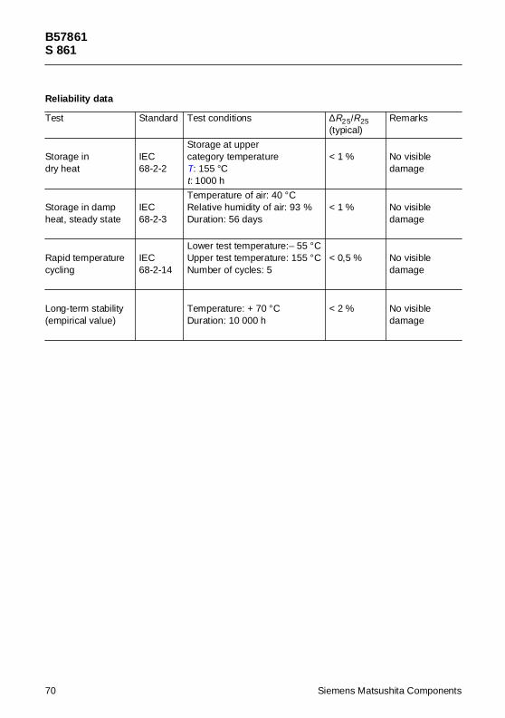
B57861S 861
Reliability data
Test Standard Test conditions ∆R25/R25(typical)
Remarks
Storage indry heat
IEC68-2-2
Storage at uppercategory temperatureT: 155 °Ct: 1000 h
< 1 % No visibledamage
Storage in dampheat, steady state
IEC68-2-3
Temperature of air: 40 °CRelative humidity of air: 93 %Duration: 56 days
< 1 % No visibledamage
Rapid temperaturecycling
IEC68-2-14
Lower test temperature:– 55 °CUpper test temperature: 155 °CNumber of cycles: 5
< 0,5 % No visibledamage
Long-term stability(empirical value)
Temperature: + 70 °CDuration: 10 000 h
< 2 % No visibledamage
70 Siemens Matsushita Components
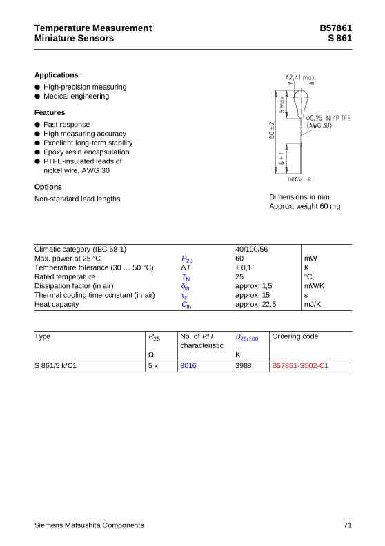
Temperature MeasurementMiniature Senso rs
B57861S 861
App lications
High-precision measuring Medical engineering
Features
Fast response High measuring accuracy Excellent long-term stability Epoxy resin encapsulation PTFE-insulated leads of
nickel wire, AWG 30
Options
Non-standard lead lengths
Climatic category (IEC 68-1)Max. power at 25 °C P25Temperature tolerance (30 … 50 °C) ∆TRated temperature TNDissipation factor (in air) δthThermal cooling time constant (in air) τcHeat capacity Cth
40/100/5660± 0,125approx. 1,5approx. 15approx. 22,5
mWK°CmW/KsmJ/K
Type R25
Ω
No. of R/Tcharacteristic
B25/100
K
Ordering code
S 861/5 k/C1 5 k 8016 3988 B57861-S502-C1
Dimensions in mmApprox. weight 60 mg
Siemens Matsushita Components 71
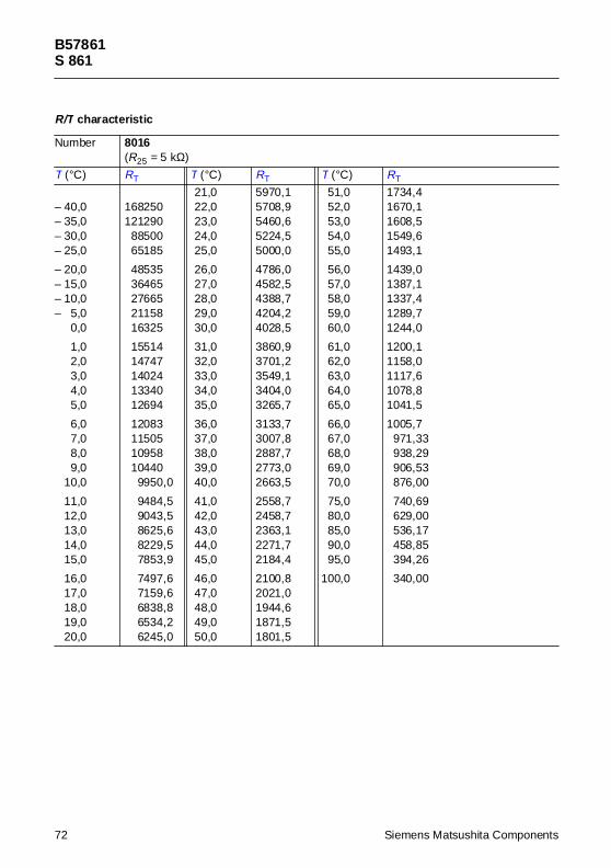
B57861S 861
R/T characteristic
Number 8016(R25 = 5 kΩ)
T (°C) RT T (°C) RT T (°C) RT
– 40,0– 35,0– 30,0– 25,0
– 20,0– 15,0– 10,0– 5,0– 0,0
– 1,0– 2,0– 3,0– 4,0– 5,0
– 6,0– 7,0– 8,0– 9,0– 10,0
– 11,0– 12,0– 13,0– 14,0– 15,0
– 16,0– 17,0– 18,0– 19,0– 20,0
168250121290
8850065185
4853536465276652115816325
1551414747140241334012694
12083115051095810440
9950,0
9484,59043,58625,68229,57853,9
7497,67159,66838,86534,26245,0
21,022,023,024,025,0
26,027,028,029,030,0
31,032,033,034,035,0
36,037,038,039,040,0
41,042,043,044,045,0
46,047,048,049,050,0
5970,15708,95460,65224,55000,0
4786,04582,54388,74204,24028,5
3860,93701,23549,13404,03265,7
3133,73007,82887,72773,02663,5
2558,72458,72363,12271,72184,4
2100,82021,01944,61871,51801,5
51,052,053,054,055,0
56,057,058,059,060,0
61,062,063,064,065,0
66,067,068,069,070,0
75,080,085,090,095,0
100,0
1734,41670,11608,51549,61493,1
1439,01387,11337,41289,71244,0
1200,11158,01117,61078,81041,5
1005,7971,33938,29906,53876,00
740,69629,00536,17458,85394,26
340,00
72 Siemens Matsushita Components
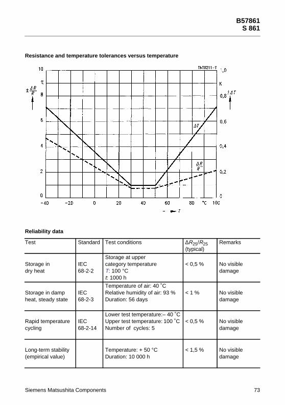
Siemens Matsushita C
Resistance and tempe
Reliability data
Test S
Storage indry heat
I6
Storage in dampheat, steady state
I6
Rapid temperaturecycling
I6
Long-term stability(empirical value)
rature tolerances versus temperature
tandard Test conditions ∆R25/R25(typical)
Remarks
EC8-2-2
Storage at uppercategory temperatureT: 100 °Ct: 1000 h
< 0,5 % No visibledamage
ECTemperature of air: 40 ˚CRelative humidity of air: 93 % < 1 % No visible
B57861S 861
omponents 73
8-2-3 Duration: 56 days damage
EC8-2-14
Lower test temperature:– 40 ˚CUpper test temperature: 100 ˚CNumber of cycles: 5
< 0,5 % No visibledamage
Temperature: + 50 °CDuration: 10 000 h
< 1,5 % No visibledamage
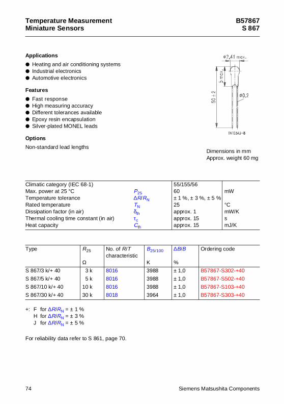
Temperature MeasurementMiniature Senso rs
B57867S 867
App lications
Heating and air conditioning systems Industrial electronics Automotive electronics
Features
Fast response High measuring accuracy Different tolerances available Epoxy resin encapsulation Silver-plated MONEL leads
Options
Non-standard lead lengths
+: F for ∆R/RN = ± 1 %H for ∆R/RN = ± 3 %J for ∆R/RN = ± 5 %
For reliability data refer to S 861, page 70.
Climatic category (IEC 68-1)Max. power at 25 °C P25Temperature tolerance ∆R/RNRated temperature TNDissipation factor (in air) δthThermal cooling time constant (in air) τcHeat capacity Cth
55/155/5660± 1 %, ± 3 %, ± 5 %25approx. 1approx. 15approx. 15
mW
°CmW/KsmJ/K
Type R25
Ω
No. of R/Tcharacteristic
B25/100
K
∆B/B
%
Ordering code
S 867/3 k/+ 40 3 k 8016 3988 ± 1,0 B57867-S302-+40
S 867/5 k/+ 40 5 k 8016 3988 ± 1,0 B57867-S502-+40
S 867/10 k/+ 40 10 k 8016 3988 ± 1,0 B57867-S103-+40
S 867/30 k/+ 40 30 k 8018 3964 ± 1,0 B57867-S303-+40
Dimensions in mmApprox. weight 60 mg
74 Siemens Matsushita Components
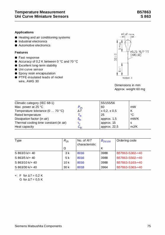
Temperature MeasurementUni Curve Miniature Senso rs
B57863S 863
App lications
Heating and air conditioning systems Industrial electronics Automotive electronics
Features
Fast response Accuracy of 0,2 K between 0 °C and 70 °C Excellent long-term stability Uni curve sensor Epoxy resin encapsulation PTFE-insulated leads of nickel
wire, AWG 30
+: F for ∆T = 0,2 KG for ∆T = 0,5 K
Climatic category (IEC 68-1)Max. power at 25 °C P25Temperature tolerance (0 … 70 °C) ∆TRated temperature TNDissipation factor (in air) δthThermal cooling time constant (in air) τcHeat capacity Cth
55/155/5660± 0,2, ± 0,525approx. 1,5approx. 15approx. 22,5
mWK°CmW/KsmJ/K
Type R25
Ω
No. of R/Tcharacteristic
B25/100
K
Ordering code
S 863/3 k/+ 40 3 k 8016 3988 B57863-S302-+40
S 863/5 k/+ 40 5 k 8016 3988 B57863-S502-+40
S 863/10 k/+ 40 10 k 8016 3988 B57863-S103-+40
S 863/30 k/+ 40 30 k 8018 3964 B57863-S303-+40
Dimensions in mmApprox. weight 60 mg
Siemens Matsushita Components 75
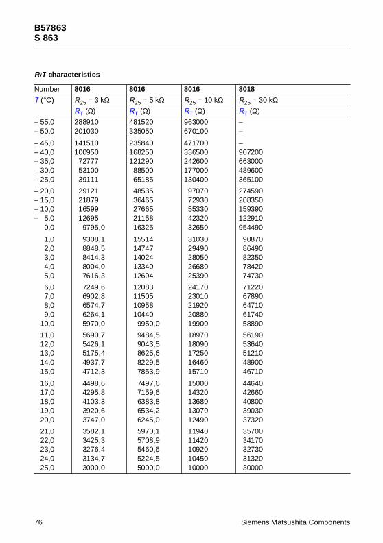
B57863S 863
R/T characteristics
Number 8016 8016 8016 8018
T (°C) R25 = 3 kΩ R25 = 5 kΩ R25 = 10 kΩ R25 = 30 kΩRT (Ω) RT (Ω) RT (Ω) RT (Ω)
– 55,0– 50,0
– 45,0– 40,0– 35,0– 30,0– 25,0
– 20,0– 15,0– 10,0– 5,0– 0,0
– 1,0– 2,0– 3,0– 4,0– 5,0
– 6,0– 7,0– 8,0– 9,0– 10,0
– 11,0– 12,0– 13,0– 14,0– 15,0
– 16,0– 17,0– 18,0– 19,0– 20,0
– 21,0– 22,0– 23,0– 24,0– 25,0
288910201030
141510100950
727775310039111
29121218791659912695
9795,0
9308,18848,58414,38004,07616,3
7249,66902,86574,76264,15970,0
5690,75426,15175,44937,74712,3
4498,64295,84103,33920,63747,0
3582,13425,33276,43134,73000,0
481520335050
235840168250121290
8850065185
4853536465276652115816325
1551414747140241334012694
12083115051095810440
9950,0
9484,59043,58625,68229,57853,9
7497,67159,66383,86534,26245,0
5970,15708,95460,65224,55000,0
963000670100
471700336500242600177000130400
9707072930553304232032650
3103029490280502668025390
2417023010219202088019900
1897018090172501646015710
1500014320136801307012490
1194011420109201045010000
––
–907200663000489600365100
274590208350159390122910954490
9087086490823507842074730
7122067890647106174058890
5619053640512104890046710
4464042660408003903037320
3570034170327303132030000
76 Siemens Matsushita Components
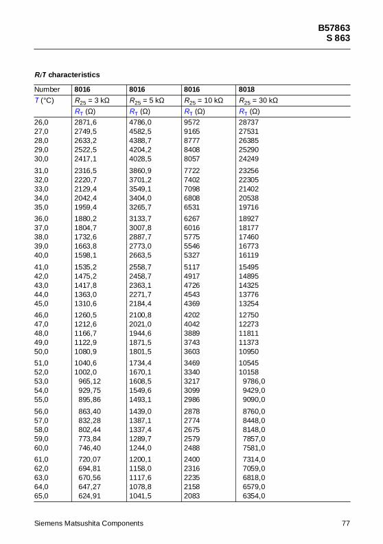
B57863S 863
26,027,028,029,030,0
31,032,033,034,035,0
36,037,038,039,040,0
41,042,043,044,045,0
46,047,048,049,050,0
51,052,053,054,055,0
56,057,058,059,060,0
61,062,063,064,065,0
2871,62749,52633,22522,52417,1
2316,52220,72129,42042,41959,4
1880,21804,71732,61663,81598,1
1535,21475,21417,81363,01310,6
1260,51212,61166,71122,91080,9
1040,61002,0
965,12929,75895,86
863,40832,28802,44773,84746,40
720,07694,81670,56647,27624,91
4786,04582,54388,74204,24028,5
3860,93701,23549,13404,03265,7
3133,73007,82887,72773,02663,5
2558,72458,72363,12271,72184,4
2100,82021,01944,61871,51801,5
1734,41670,11608,51549,61493,1
1439,01387,11337,41289,71244,0
1200,11158,01117,61078,81041,5
95729165877784088057
77227402709868086531
62676016577555465327
51174917472645434369
42024042388937433603
34693340321730992986
28782774267525792488
24002316223521582083
2873727531263852529024249
2325622305214022053819716
1892718177174601677316119
1549514895143251377613254
1275012273118111137310950
1054510158
9786,09429,09090,0
8760,08448,08148,07857,07581,0
7314,07059,06818,06579,06354,0
R/T characteristics
Number 8016 8016 8016 8018
T (°C) R25 = 3 kΩ R25 = 5 kΩ R25 = 10 kΩ R25 = 30 kΩRT (Ω) RT (Ω) RT (Ω) RT (Ω)
Siemens Matsushita Components 77
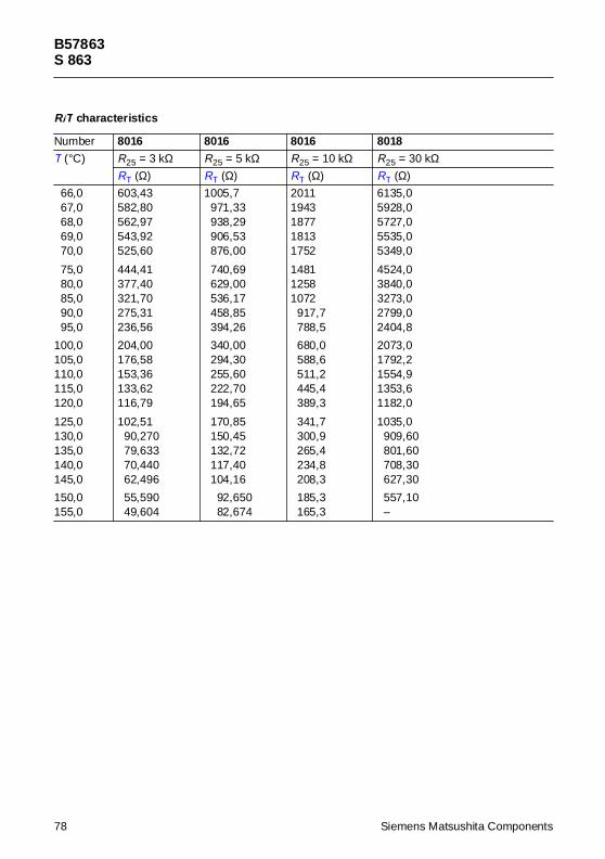
B57863S 863
66,067,068,069,070,0
75,080,085,090,095,0
100,0105,0110,0115,0120,0
125,0130,0135,0140,0145,0
150,0155,0
603,43582,80562,97543,92525,60
444,41377,40321,70275,31236,56
204,00176,58153,36133,62116,79
102,5190,27079,63370,44062,496
55,59049,604
1005,7971,33938,29906,53876,00
740,69629,00536,17458,85394,26
340,00294,30255,60222,70194,65
170,85150,45132,72117,40104,16
92,65082,674
20111943187718131752
148112581072
917,7788,5
680,0588,6511,2445,4389,3
341,7300,9265,4234,8208,3
185,3165,3
6135,05928,05727,05535,05349,0
4524,03840,03273,02799,02404,8
2073,01792,21554,91353,61182,0
1035,0909,60801,60708,30627,30
557,10–
R/T characteristics
Number 8016 8016 8016 8018
T (°C) R25 = 3 kΩ R25 = 5 kΩ R25 = 10 kΩ R25 = 30 kΩRT (Ω) RT (Ω) RT (Ω) RT (Ω)
78 Siemens Matsushita Components
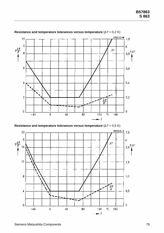
Siemens Matsushita C
Resistance and tempe
Resistance and tempe
rature tolerances versus temperature (∆T = 0,2 K)
rature tolerances versus temperature (∆T = 0,5 K)
B57863S 863
omponents 79

B57863S 863
Reliability data
Test Standard Test conditions ∆R25/R25(typical)
Remarks
Storage indry heat
IEC68-2-2
Storage at uppercategory temperatureT: 155 °Ct: 1000 h
< 1 % No visibledamage
Storage in dampheat, steady state
IEC68-2-3
Temperature of air: 40 °CRelative humidity of air: 93 %Duration: 56 days
< 1 % No visibledamage
Rapid temperaturecycling
IEC68-2-14
Lower test temperature:– 55 °CUpper test temperature: 155 °CNumber of cycles: 5
< 0,5 % No visibledamage
Long-term stability(empirical value)
Temperature: + 70 °CDuration: 10 000 h
< 2 % No visibledamage
80 Siemens Matsushita Components
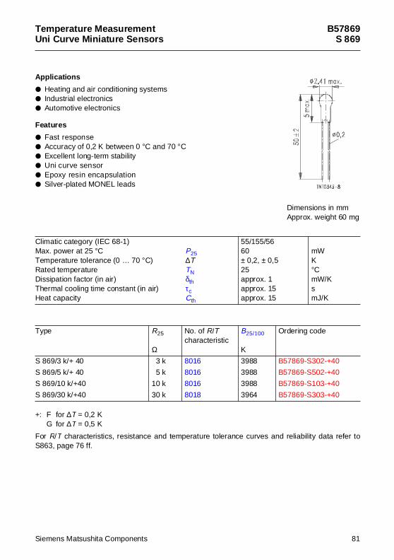
Temperature MeasurementUni Curve Miniature Senso rs
B57869S 869
App lications
Heating and air conditioning systems Industrial electronics Automotive electronics
Features
Fast response Accuracy of 0,2 K between 0 °C and 70 °C Excellent long-term stability Uni curve sensor Epoxy resin encapsulation Silver-plated MONEL leads
+: F for ∆T = 0,2 KG for ∆T = 0,5 K
For R/T characteristics, resistance and temperature tolerance curves and reliability data refer toS863, page 76 ff.
Climatic category (IEC 68-1)Max. power at 25 °C P25Temperature tolerance (0 … 70 °C) ∆TRated temperature TNDissipation factor (in air) δthThermal cooling time constant (in air) τcHeat capacity Cth
55/155/5660± 0,2, ± 0,525approx. 1approx. 15approx. 15
mWK°CmW/KsmJ/K
Type R25
Ω
No. of R/Tcharacteristic
B25/100
K
Ordering code
S 869/3 k/+ 40 3 k 8016 3988 B57869-S302-+40
S 869/5 k/+ 40 5 k 8016 3988 B57869-S502-+40
S 869/10 k/+40 10 k 8016 3988 B57869-S103-+40
S 869/30 k/+40 30 k 8018 3964 B57869-S303-+40
Dimensions in mmApprox. weight 60 mg
Siemens Matsushita Components 81
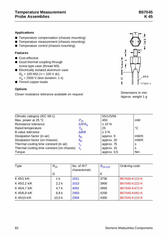
Temperature MeasurementProbe Assemblies
B57045K 45
App lications
Temperature compensation (chassis mounting) Temperature measurement (chassis mounting) Temperature control (chassis mounting)
Features
Cost-effective Good thermal coupling through
screw-type case (thread M3) Electrically isolated aluminum case
Ris > 100 MΩ (V = 100 V dc)Vis = 2500 V (test duration: 1 s)
Tinned copper leads
Options
Closer resistance tolerance available on request
Climatic category (IEC 68-1)Max. power at 25 °C P25Resistance tolerance ∆R/RNRated temperature TNB value tolerance ∆B/BDissipation factor (in air) δthDissipation factor (on chassis) δthThermal cooling time constant (in air) τcThermal cooling time constant (on chassis) τcTorque
55/125/56450± 10 %25± 3 %approx. 9approx. 20approx. 75approx. 15approx. 0,5
mW
°C
mW/KmW/KssNm
Type R25
Ω
No. of R/Tcharacteristic
B25/100
K
Ordering code
K 45/1 k/K 1 k 1011 3730 B57045-K102-K
K 45/2,2 k/K 2,2 k 1013 3900 B57045-K222-K
K 45/4,7 k/K 4,7 k 4001 3950 B57045-K472-K
K 45/6,8 k/K 6,8 k 2903 4200 B57045-K682-K
K 45/10 k/K 10,0 k 2904 4300 B57045-K103-K
Dimensions in mmApprox. weight 1 g
82 Siemens Matsushita Components
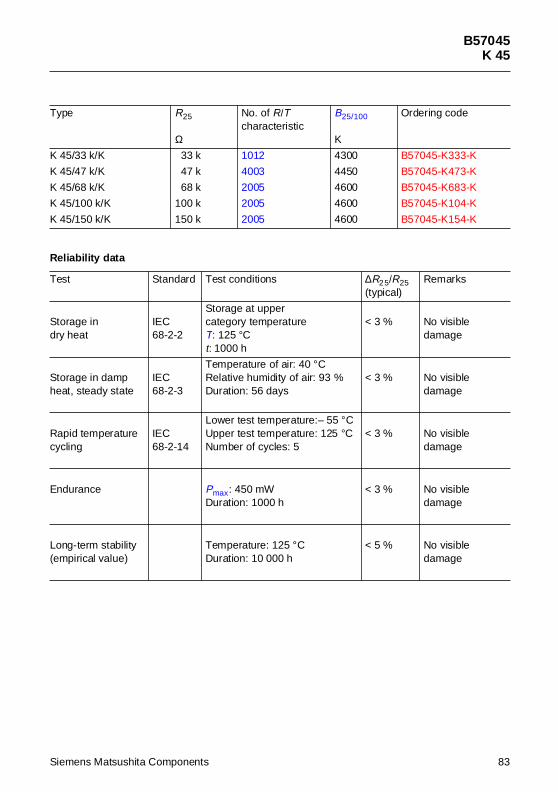
B57045K 45
K 45/33 k/K 33 k 1012 4300 B57045-K333-K
K 45/47 k/K 47 k 4003 4450 B57045-K473-K
K 45/68 k/K 68 k 2005 4600 B57045-K683-K
K 45/100 k/K 100 k 2005 4600 B57045-K104-K
K 45/150 k/K 150 k 2005 4600 B57045-K154-K
Reliabil ity data
Test Standard Test conditions ∆R25/R25(typical)
Remarks
Storage indry heat
IEC68-2-2
Storage at uppercategory temperatureT: 125 °Ct: 1000 h
< 3 % No visibledamage
Storage in dampheat, steady state
IEC68-2-3
Temperature of air: 40 °CRelative humidity of air: 93 %Duration: 56 days
< 3 % No visibledamage
Rapid temperaturecycling
IEC68-2-14
Lower test temperature:– 55 °CUpper test temperature: 125 °CNumber of cycles: 5
< 3 % No visibledamage
Endurance Pmax: 450 mWDuration: 1000 h
< 3 % No visibledamage
Long-term stability(empirical value)
Temperature: 125 °CDuration: 10 000 h
< 5 % No visibledamage
Type R25
Ω
No. of R/Tcharacteristic
B25/100
K
Ordering code
Siemens Matsushita Components 83
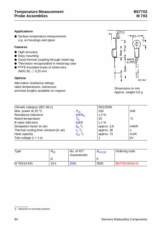
Temperature MeasurementProbe Assemblies
B57703M 703
App lications
Surface temperature measurement,e.g. on housings and pipes
Features
High accuracy Easy mounting Good thermal coupling through metal tag Thermistor encapsulated in metal-tag case PTFE-insulated leads of nickel wire,
AWG 30, ∅ 0,25 mm
Options
Alternative resistance ratings,rated temperatures, tolerancesand lead lengths available on request
1) Depends on mounting situation
Climatic category (IEC 68-1)Max. power at 25 °C P25Resistance tolerance ∆R/RNRated temperature TNB value tolerance ∆B/BDissipation factor (in air) δth 1)Thermal cooling time constant (in air) τc
1)Heat capacity Cth 1)Test voltage (t = 1 s)
55/125/56150± 2 %25± 1 %approx. 2,6approx. 28approx. 731
mW
°C
mW/KsmJ/KkV
Type R25
Ω
No. of R/Tcharacteristic
B25/100
K
Ordering code
M 703/10 k/G 10 k 2001 3920 B57703-M103-G
Dimensions in mmApprox. weight 0,8 g
84 Siemens Matsushita Components
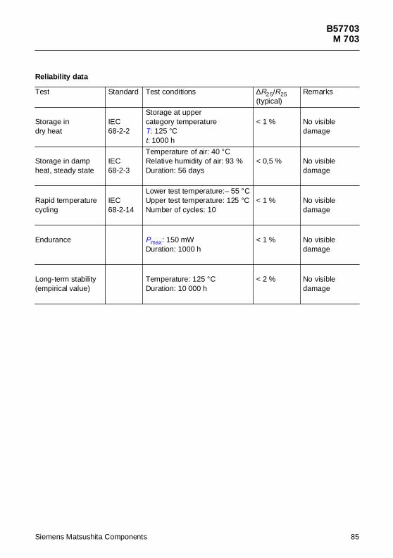
B57703M 703
Reliability data
Test Standard Test conditions ∆R25/R25(typical)
Remarks
Storage indry heat
IEC68-2-2
Storage at uppercategory temperatureT: 125 °Ct: 1000 h
< 1 % No visibledamage
Storage in dampheat, steady state
IEC68-2-3
Temperature of air: 40 °CRelative humidity of air: 93 %Duration: 56 days
< 0,5 % No visibledamage
Rapid temperature cycling
IEC68-2-14
Lower test temperature:– 55 °CUpper test temperature: 125 °CNumber of cycles: 10
< 1 % No visibledamage
Endurance Pmax: 150 mWDuration: 1000 h
< 1 % No visibledamage
Long-term stability(empirical value)
Temperature: 125 °CDuration: 10 000 h
< 2 % No visibledamage
Siemens Matsushita Components 85
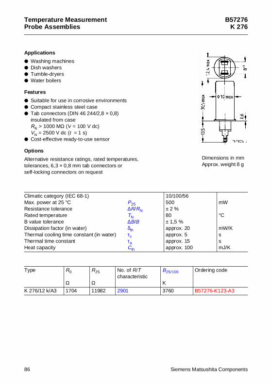
Temperature MeasurementProbe Assemblies
B57276K 276
App lications
Washing machines Dish washers Tumble-dryers Water boilers
Features
Suitable for use in corrosive environments Compact stainless steel case Tab connectors (DIN 46 244/2,8 × 0,8)
insulated from caseRis > 1000 MΩ (V = 100 V dc)Vis = 2500 V dc (t = 1 s)
Cost-effective ready-to-use sensor
Options
Alternative resistance ratings, rated temperatures,tolerances, 6,3 × 0,8 mm tab connectors orself-locking connectors on request
Climatic category (IEC 68-1)Max. power at 25 °C P25Resistance tolerance ∆R/RNRated temperature TNB value tolerance ∆B/BDissipation factor (in water) δthThermal cooling time constant (in water) τcThermal time constant τaHeat capacity Cth
10/100/56500± 2 %80± 1,5 %approx. 20approx. 5approx. 15approx. 100
mW
°C
mW/KssmJ/K
Type R0
Ω
R25
Ω
No. of R/Tcharacteristic
B25/100
K
Ordering code
K 276/12 k/A3 1704 11982 2901 3760 B57276-K123-A3
Dimensions in mmApprox. weight 8 g
86 Siemens Matsushita Components
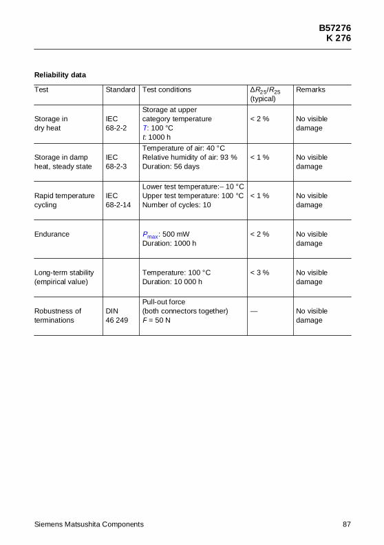
B57276K 276
Reliability data
Test Standard Test conditions ∆R25/R25(typical)
Remarks
Storage indry heat
IEC68-2-2
Storage at uppercategory temperatureT: 100 °Ct: 1000 h
< 2 % No visibledamage
Storage in dampheat, steady state
IEC68-2-3
Temperature of air: 40 °CRelative humidity of air: 93 %Duration: 56 days
< 1 % No visibledamage
Rapid temperaturecycling
IEC68-2-14
Lower test temperature:– 10 °CUpper test temperature: 100 °CNumber of cycles: 10
< 1 % No visibledamage
Endurance Pmax: 500 mWDuration: 1000 h
< 2 % No visibledamage
Long-term stability(empirical value)
Temperature: 100 °CDuration: 10 000 h
< 3 % No visibledamage
Robustness of terminations
DIN46 249
Pull-out force(both connectors together)F = 50 N
— No visibledamage
Siemens Matsushita Components 87
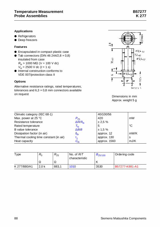
Temperature MeasurementProbe Assemblies
B57277K 277
App lications
Refrigerators Deep freezers
Features
Encapsulated in compact plastic case Tab connectors (DIN 46 244/2,8 × 0,8)
insulated from caseRis > 1000 MΩ (V = 100 V dc)Vis = 2500 V dc (t = 1 s)
Internal construction conforms toVDE 007/protection class II
Options
Alternative resistance ratings, rated temperatures,tolerances and 6,3 × 0,8 mm connectors availableon request
Climatic category (IEC 68-1)Max. power at 25 °C P25Resistance tolerance ∆R/RNRated temperature TNB value tolerance ∆B/BDissipation factor (in air) δthThermal cooling time constant (in air) τcHeat capacity Cth
40/100/56420± 2,5 %5± 1,5 %approx. 12approx. 130approx. 1560
mW
°C
mW/KsmJ/K
Type R0
Ω
R25
Ω
No. of R/Tcharacteristic
B25/100
K
Ordering code
K 277/880/A1 2,0 k 883,1 1010 3530 B57277-K881-A1
Dimensions in mmApprox. weight 5 g
88 Siemens Matsushita Components
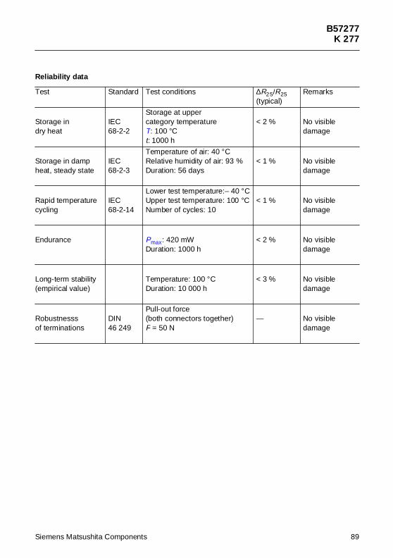
B57277K 277
Reliability data
Test Standard Test conditions ∆R25/R25(typical)
Remarks
Storage indry heat
IEC68-2-2
Storage at uppercategory temperatureT: 100 °Ct: 1000 h
< 2 % No visibledamage
Storage in dampheat, steady state
IEC68-2-3
Temperature of air: 40 °CRelative humidity of air: 93 %Duration: 56 days
< 1 % No visibledamage
Rapid temperaturecycling
IEC68-2-14
Lower test temperature:– 40 °CUpper test temperature: 100 °CNumber of cycles: 10
< 1 % No visibledamage
Endurance Pmax: 420 mWDuration: 1000 h
< 2 % No visibledamage
Long-term stability(empirical value)
Temperature: 100 °CDuration: 10 000 h
< 3 % No visibledamage
Robustnesssof terminations
DIN46 249
Pull-out force(both connectors together)F = 50 N
— No visibledamage
Siemens Matsushita Components 89
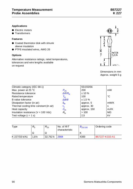
Temperature MeasurementProbe Assemblies
B57227K 227
App lications
Electric motors Transformers
Features
Coated thermistor disk with shrunksleeve insulation
PTFE-insulated wires, AWG 26
Options
Alternative resistance ratings, rated temperatures,tolerances and wire lengths availableon request
Climatic category (IEC 68-1)Max. power at 25 °C P25Resistance tolerance ∆R/RNRated temperature TNB value tolerance ∆B/BDissipation factor (in air) δthThermal cooling time constant (in air) τcHeat capacity CthInsulation resistance (V = 100 Vdc) RisTest voltage (t = 1 s)
55/155/56200± 10 %100± 1,5 %approx. 5approx. 30approx. 150> 1002,5
mW
°C
mW/KsmJ/KMΩkV
Type R0
Ω
R25
Ω
No. of R/Tcharacteristic
B25/100
K
Ordering code
K 227/33 k/A1 1,8 k 32,762 k 2904 4300 B57227-K333-A1
Dimensions in mmApprox. weight 5 g
90 Siemens Matsushita Components
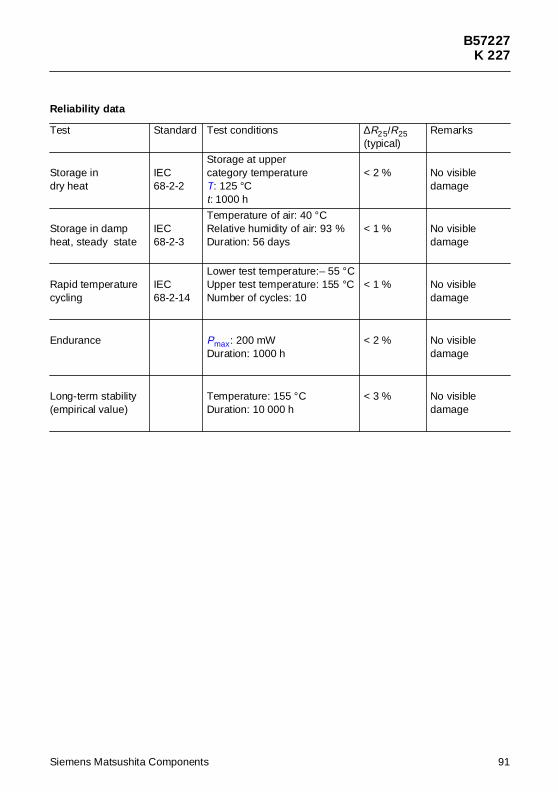
B57227K 227
Reliability data
Test Standard Test conditions ∆R25/R25(typical)
Remarks
Storage indry heat
IEC68-2-2
Storage at uppercategory temperatureT: 125 °Ct: 1000 h
< 2 % No visibledamage
Storage in dampheat, steady state
IEC68-2-3
Temperature of air: 40 °CRelative humidity of air: 93 %Duration: 56 days
< 1 % No visibledamage
Rapid temperaturecycling
IEC68-2-14
Lower test temperature:– 55 °CUpper test temperature: 155 °CNumber of cycles: 10
< 1 % No visibledamage
Endurance Pmax: 200 mWDuration: 1000 h
< 2 % No visibledamage
Long-term stability(empirical value)
Temperature: 155 °CDuration: 10 000 h
< 3 % No visibledamage
Siemens Matsushita Components 91
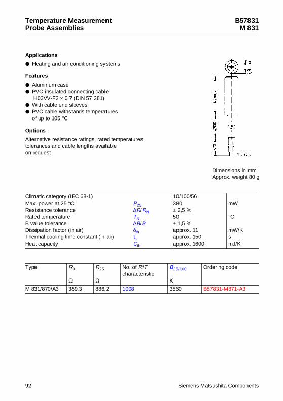
Temperature MeasurementProbe Assemblies
B57831M 831
App lications
Heating and air conditioning systems
Features
Aluminum case PVC-insulated connecting cable
H03VV-F2 × 0,7 (DIN 57 281) With cable end sleeves PVC cable withstands temperatures
of up to 105 °C
Options
Alternative resistance ratings, rated temperatures,tolerances and cable lengths availableon request
Climatic category (IEC 68-1)Max. power at 25 °C P25Resistance tolerance ∆R/RNRated temperature TNB value tolerance ∆B/BDissipation factor (in air) δthThermal cooling time constant (in air) τcHeat capacity Cth
10/100/56380± 2,5 %50± 1,5 %approx. 11approx. 150approx. 1600
mW
°C
mW/KsmJ/K
Type R0
Ω
R25
Ω
No. of R/Tcharacteristic
B25/100
K
Ordering code
M 831/870/A3 359,3 886,2 1008 3560 B57831-M871-A3
Dimensions in mmApprox. weight 80 g
92 Siemens Matsushita Components
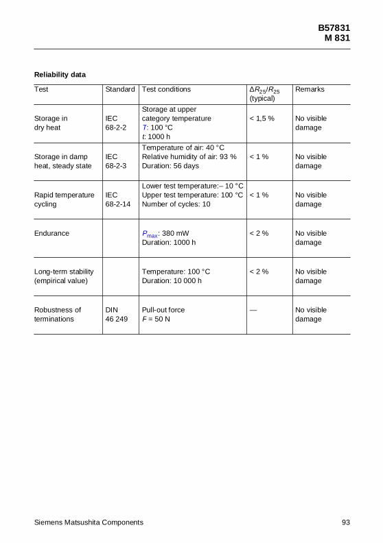
B57831M 831
Reliability data
Test Standard Test conditions ∆R25/R25(typical)
Remarks
Storage indry heat
IEC68-2-2
Storage at uppercategory temperatureT: 100 °Ct: 1000 h
< 1,5 % No visibledamage
Storage in dampheat, steady state
IEC68-2-3
Temperature of air: 40 °CRelative humidity of air: 93 %Duration: 56 days
< 1 % No visibledamage
Rapid temperaturecycling
IEC68-2-14
Lower test temperature:– 10 °CUpper test temperature: 100 °CNumber of cycles: 10
< 1 % No visibledamage
Endurance Pmax: 380 mWDuration: 1000 h
< 2 % No visibledamage
Long-term stability(empirical value)
Temperature: 100 °CDuration: 10 000 h
< 2 % No visibledamage
Robustness ofterminations
DIN46 249
Pull-out forceF = 50 N
— No visibledamage
Siemens Matsushita Components 93
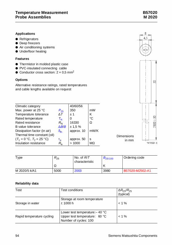
Temperature MeasurementProbe Assemblies
B57020M 2020
App lications
Refrigerators Deep freezers Air conditioning systems Underfloor heating
Features
Thermistor in molded plastic case PVC-insulated connecting cable Conductor cross section: 2 × 0,5 mm2
Options
Alternative resistance ratings, rated temperaturesand cable lengths available on request
Climatic categoryMax. power at 25 °C P25Temperature tolerance ∆TRated temperature TNRated resistance RNB value tolerance ∆B/BDissipation factor (in air) δthThermal time constant (oil)(T1 = 0 °C, T2 = 25 °C) τaInsulation resistance Ris
40/60/56350± 1016330± 1,5 %approx. 10
approx. 50> 1000
mWK°CΩ
mW/K
sMΩ
Type R25
Ω
No. of R/Tcharacteristic
B25/100
K
Ordering code
M 2020/5 k/A1 5000 2003 3980 B57020-M2502-A1
Reliabil ity data
Test Test conditions ∆R25/R25(typical)
Storage in waterStorage at room temperaturet: 1000 h < 1 %
Rapid temperature cyclingLower test temperature:– 40 °CUpper test temperature: 60 °CNumber of cycles: 100
< 1 %
Dimensionsin mm
94 Siemens Matsushita Components
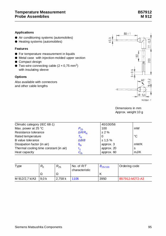
Temperature MeasurementProbe Assemblies
B57912M 912
App lications
Air conditioning systems (automobiles) Heating systems (automobiles)
Features
For temperature measurement in liquids Metal case with injection-molded upper section Compact design Two-wire connecting cable (2 × 0,75 mm2)
with insulating sleeve
Options
Also available with connectorsand other cable lengths
Climatic category (IEC 68-1)Max. power at 25 °C P25Resistance tolerance ∆R/RNRated temperature TNB value tolerance ∆B/BDissipation factor (in air) δthThermal cooling time constant (in air) τcHeat capacity Cth
40/100/56100± 2 %0± 1,5 %approx. 3approx. 20approx. 60
mW
°C
mW/KsmJ/K
Type R0
Ω
R25
Ω
No. of R/Tcharacteristic
B25/100
K
Ordering code
M 912/2,7 k/A3 9,0 k 2,758 k 1106 3950 B57912-M272-A3
Dimensions in mmApprox. weight 10 g
Siemens Matsushita Components 95
B57912M 912
Reliability data
Test Standard Test conditions ∆R25/R25(typical)
Remarks
Storage indry heat
IEC68-2-2
Storage at uppercategory temperatureT: 100 °Ct: 1000 h
< 1 % No visibledamage
Storage in dampheat, steady state
IEC68-2-3
Temperature of air: 40 °CRelative humidity of air: 93 %Duration: 56 days
< 0,5 % No visibledamage
Rapid temperaturecycling
IEC68-2-14
Lower test temperature:– 40 °CUpper test temperature: 100 °CNumber of cycles: 10
< 1 % No visibledamage
Endurance Pmax: 100 mWDuration: 1000 h
< 2 % No visibledamage
Long-term stability(empirical value)
Temperature: 100 °CDuration: 10 000 h
< 2 % No visibledamage
Robustness of terminations
DIN46 249
Pull-out forceF = 100 N
— No visibledamage
96 Siemens Matsushita Components
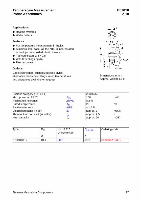
Temperature MeasurementProbe Assemblies
B57010Z 10
App lications
Heating systems Water boilers
Features
For temperature measurement in liquids Stainless steel case (a); the NTC is incorporated
in the injection-molded plastic base (c) Tab connectors 2,8 × 0,8 With O sealing ring (b) Fast response
Options
Cable connectors, customized case styles,alternative resistance ratings, rated temperaturesand tolerances available on request
Climatic category (IEC 68-1)Max. power at 25 °C P25Resistance tolerance ∆R/RNRated temperature TNB value tolerance ∆B/BDissipation factor (in air) δthThermal time constant (in water) τaHeat capacity Cth
25/100/56100± 2 %25± 1,5 %approx. 9approx. 2,5approx. 20
mW
°C
mW/KsmJ/K
Type R25
Ω
No. of R/Tcharacteristic
B25/100
K
Ordering code
Z 10/10 k/G 10 k 2001 3920 B57010-Z103-G
Dimensions in mmApprox. weight 4,5 g
Siemens Matsushita Components 97

B57010Z 10
Reliability data
Test Standard Test conditions ∆R25/R25(typical)
Remarks
Storage indry heat
IEC68-2-2
Storage at uppercategory temperatureT: 100 °Ct: 1000 h
< 1 % No visibledamage
Storage in dampheat, steady state
IEC68-2-3
Temperature of air: 40 °CRelative humidity of air: 93 %Duration: 56 days
< 0,5 % No visibledamage
Rapid temperaturecycling
IEC68-2-14
Lower test temperature:– 25 °CUpper test temperature: 100 °CNumber of cycles: 10
< 1 % No visibledamage
Endurance Pmax: 100 mWDuration: 1000 h
< 2 % No visibledamage
Long-term stability(empirical value)
Temperature: 100 °CDuration: 10 000 h
< 2 % No visibledamage
Robustness of terminations
DIN46 249
Pull-out force(both connectors together)F = 50 N
— No visibledamage
98 Siemens Matsushita Components
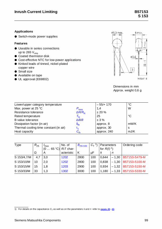
Inrush Current Limiting B57153S 153
App lications
Switch-mode power supplies
Features
Useable in series connectionsup to 265 Vrms
Coated thermistor disk Cost-effective NTC for low-power applications Kinked leads of tinned, nickel-plated
copper wire Small size Available on tape UL approval (E69802)
1) For details on the capacitance CT as well as on the parameters k and n refer to pages 38–40.
Lower/upper category temperatureMax. power at 25 °C PmaxResistance tolerance ∆R/RNRated temperature TNB value tolerance ∆B/BDissipation factor (in air) δthThermal cooling time constant (in air) τcHeat capacity Cth
– 55/+ 1701,4± 20 %25± 3 %approx. 8approx. 30approx. 240
°CW
°C
mW/KsmJ/K
Type R25
Ω
Imax(0 … 65 °C)A
No. ofR/T char-acteristic
B25/100
K
CT 1)
µF
Parametersfor R(I) 1)
Ordering code
k n
S 153/4,7/M 4,7 3,0 1202 2800 100 0,644 – 1,30 B57153-S479-M
S 153/10/M 10 2,0 1202 2800 100 0,838 – 1,30 B57153-S100-M
S 153/15/M 15 1,8 1203 2900 100 0,934 – 1,32 B57153-S150-M
S 153/33/M 33 1,3 1302 3000 100 1,180 – 1,33 B57153-S330-M
Dimensions in mmApprox. weight 0,6 g
Siemens Matsushita Components 99
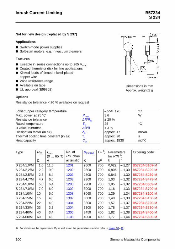
Inrush Current Limiting B57234S 234
Not for new des ign (replaced by S 237)
App lications
Switch-mode power supplies Soft-start motors, e.g. in vacuum cleaners
Features
Useable in series connections up to 265 Vrms Coated thermistor disk for line applications Kinked leads of tinned, nickel-plated
copper wire Wide resistance range Available on tape UL approval (E69802)
Options
Resistance tolerance < 20 % available on request
1) For details on the capacitance CT as well as on the parameters k and n refer to pages 38–40.
Lower/upper category temperatureMax. power at 25 °C PmaxResistance tolerance ∆R/RNRated temperature TNB value tolerance ∆B/BDissipation factor (in air) δthThermal cooling time constant (in air) τcHeat capacity Cth
– 55/+ 1703,6± 20 %25± 3 %approx. 17approx. 90approx. 1530
°CW
°C
mW/KsmJ/K
Type R25
Ω
Imax(0 … 65 °C)A
No. ofR/T char-acteristic
B25/100
K
CT 1)
µF
Parametersfor R(I) 1)
Ordering code
k n
S 234/1,0/M 1,0 11,5 1201 2600 700 0,622 – 1,27 B57234-S109-MS 234/2,2/M 2,2 9,0 1202 2800 700 0,806 – 1,30 B57234-S229-MS 234/2,5/M 2,5 8,4 1202 2800 700 0,843 – 1,30 B57234-S259-MS 234/4,7/M 4,7 6,6 1203 2900 700 1,03 – 1,32 B57234-S479-MS 234/5,0/M 5,0 6,4 1203 2900 700 1,05 – 1,32 B57234-S509-MS 234/7,0/M 7,0 6,0 1302 3000 700 1,16 – 1,33 B57234-S709-MS 234/10/M 10 5,0 1308 3060 700 1,29 – 1,34 B57234-S100-MS 234/15/M 15 4,0 1302 3000 700 1,49 – 1,33 B57234-S150-MS 234/22/M 22 4,0 1304 3300 700 1,57 – 1,37 B57234-S220-MS 234/33/M 33 3,3 1304 3300 900 1,78 – 1,37 B57234-S330-MS 234/40/M 40 3,4 1306 3450 400 1,82 – 1,38 B57234-S400-MS 234/60/M 60 4,0 1103 4000 400 1,77 – 1,44 B57234-S600-M
Dimensions in mmApprox. weight 2 g
100 Siemens Matsushita Components
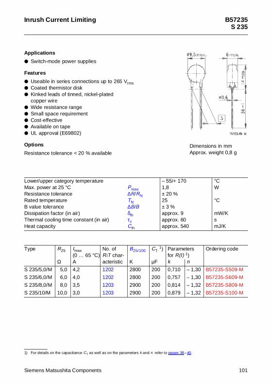
Inrush Current Limiting B57235S 235
App lications
Switch-mode power supplies
Features
Useable in series connections up to 265 Vrms Coated thermistor disk Kinked leads of tinned, nickel-plated
copper wire Wide resistance range Small space requirement Cost-effective Available on tape UL approval (E69802)
Options
Resistance tolerance < 20 % available
1) For details on the capacitance CT as well as on the parameters k and n refer to pages 38–40.
Lower/upper category temperatureMax. power at 25 °C PmaxResistance tolerance ∆R/RNRated temperature TNB value tolerance ∆B/BDissipation factor (in air) δthThermal cooling time constant (in air) τcHeat capacity Cth
– 55/+ 1701,8± 20 %25± 3 %approx. 9approx. 60approx. 540
°CW
°C
mW/KsmJ/K
Type R25
Ω
Imax(0 … 65 °C)A
No. ofR/T char-acteristic
B25/100
K
CT 1)
µF
Parametersfor R(I) 1)
Ordering code
k n
S 235/5,0/M 5,0 4,2 1202 2800 200 0,710 – 1,30 B57235-S509-M
S 235/6,0/M 6,0 4,0 1202 2800 200 0,757 – 1,30 B57235-S609-M
S 235/8,0/M 8,0 3,5 1203 2900 200 0,814 – 1,32 B57235-S809-M
S 235/10/M 10,0 3,0 1203 2900 200 0,879 – 1,32 B57235-S100-M
Dimensions in mmApprox. weight 0,8 g
Siemens Matsushita Components 101
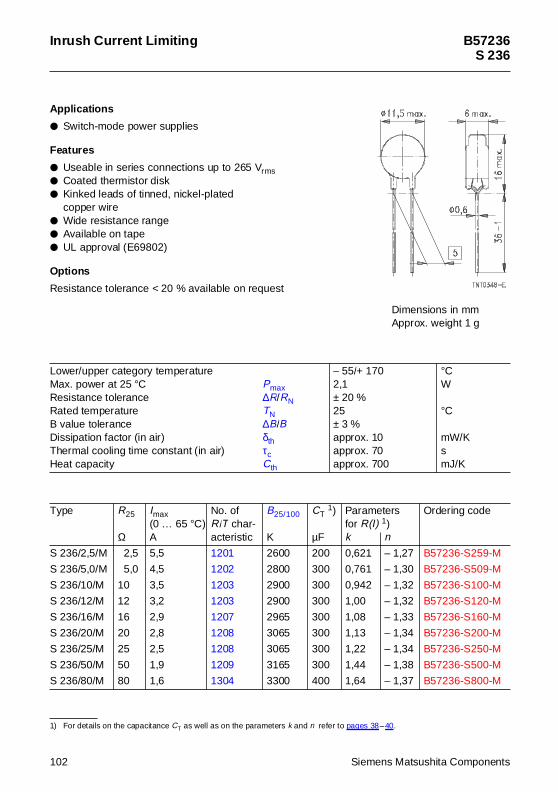
Inrush Current Limiting B57236S 236
App lications
Switch-mode power supplies
Features
Useable in series connections up to 265 Vrms Coated thermistor disk Kinked leads of tinned, nickel-plated
copper wire Wide resistance range Available on tape UL approval (E69802)
Options
Resistance tolerance < 20 % available on request
1) For details on the capacitance CT as well as on the parameters k and n refer to pages 38–40.
Lower/upper category temperatureMax. power at 25 °C PmaxResistance tolerance ∆R/RNRated temperature TNB value tolerance ∆B/BDissipation factor (in air) δthThermal cooling time constant (in air) τcHeat capacity Cth
– 55/+ 1702,1± 20 %25± 3 %approx. 10approx. 70approx. 700
°CW
°C
mW/KsmJ/K
Type R25
Ω
Imax(0 … 65 °C)A
No. ofR/T char-acteristic
B25/100
K
CT 1)
µF
Parametersfor R(I) 1)
Ordering code
k n
S 236/2,5/M 2,5 5,5 1201 2600 200 0,621 – 1,27 B57236-S259-M
S 236/5,0/M 5,0 4,5 1202 2800 300 0,761 – 1,30 B57236-S509-M
S 236/10/M 10 3,5 1203 2900 300 0,942 – 1,32 B57236-S100-M
S 236/12/M 12 3,2 1203 2900 300 1,00 – 1,32 B57236-S120-M
S 236/16/M 16 2,9 1207 2965 300 1,08 – 1,33 B57236-S160-M
S 236/20/M 20 2,8 1208 3065 300 1,13 – 1,34 B57236-S200-M
S 236/25/M 25 2,5 1208 3065 300 1,22 – 1,34 B57236-S250-M
S 236/50/M 50 1,9 1209 3165 300 1,44 – 1,38 B57236-S500-M
S 236/80/M 80 1,6 1304 3300 400 1,64 – 1,37 B57236-S800-M
Dimensions in mmApprox. weight 1 g
102 Siemens Matsushita Components
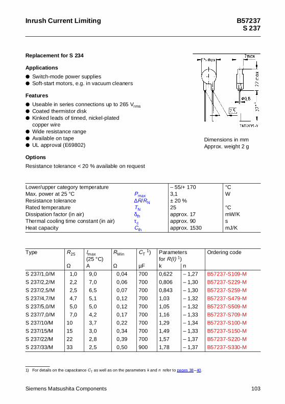
Inrush Current Limiting B57237S 237
Replacement for S 234
App lications
Switch-mode power supplies Soft-start motors, e.g. in vacuum cleaners
Features
Useable in series connections up to 265 Vrms Coated thermistor disk Kinked leads of tinned, nickel-plated
copper wire Wide resistance range Available on tape UL approval (E69802)
Options
Resistance tolerance < 20 % available on request
1) For details on the capacitance CT as well as on the parameters k and n refer to pages 38–40.
Lower/upper category temperatureMax. power at 25 °C PmaxResistance tolerance ∆R/RNRated temperature TNDissipation factor (in air) δthThermal cooling time constant (in air) τcHeat capacity Cth
– 55/+ 1703,1± 20 %25approx. 17approx. 90approx. 1530
°CW
°CmW/KsmJ/K
Type R25
Ω
Imax(25 °C)A
RMin
Ω
CT 1)
µF
Parametersfor R(I) 1)
Ordering code
k n
S 237/1,0/M 1,0 9,0 0,04 700 0,622 – 1,27 B57237-S109-M
S 237/2,2/M 2,2 7,0 0,06 700 0,806 – 1,30 B57237-S229-M
S 237/2,5/M 2,5 6,5 0,07 700 0,843 – 1,30 B57237-S259-M
S 237/4,7/M 4,7 5,1 0,12 700 1,03 – 1,32 B57237-S479-M
S 237/5,0/M 5,0 5,0 0,12 700 1,05 – 1,32 B57237-S509-M
S 237/7,0/M 7,0 4,2 0,17 700 1,16 – 1,33 B57237-S709-M
S 237/10/M 10 3,7 0,22 700 1,29 – 1,34 B57237-S100-M
S 237/15/M 15 3,0 0,34 700 1,49 – 1,33 B57237-S150-M
S 237/22/M 22 2,8 0,39 700 1,57 – 1,37 B57237-S220-M
S 237/33/M 33 2,5 0,50 900 1,78 – 1,37 B57237-S330-M
Dimensions in mmApprox. weight 2 g
Siemens Matsushita Components 103
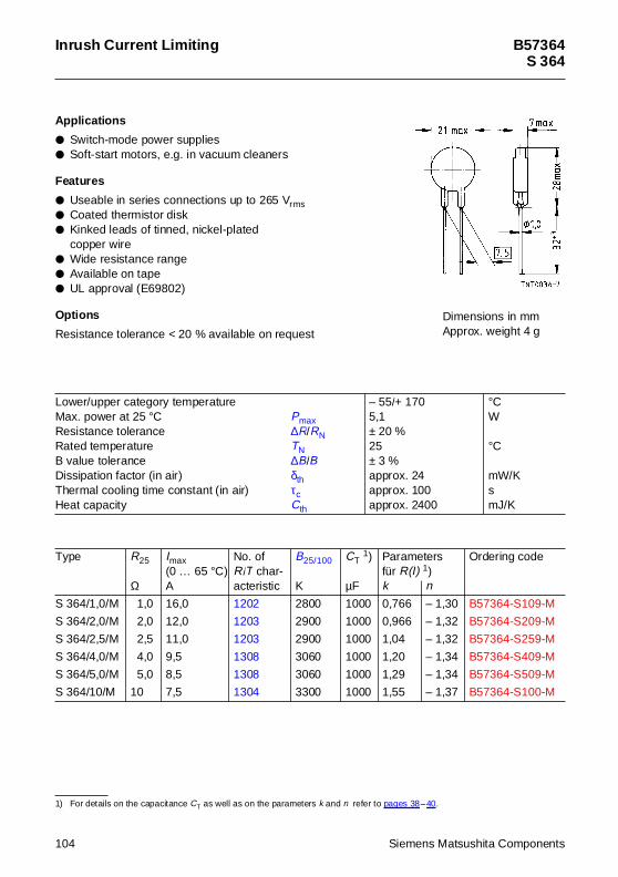
Inrush Current Limiting B57364S 364
App lications
Switch-mode power supplies Soft-start motors, e.g. in vacuum cleaners
Features
Useable in series connections up to 265 Vrms Coated thermistor disk Kinked leads of tinned, nickel-plated
copper wire Wide resistance range Available on tape UL approval (E69802)
Options
Resistance tolerance < 20 % available on request
1) For details on the capacitance CT as well as on the parameters k and n refer to pages 38–40.
Lower/upper category temperatureMax. power at 25 °C PmaxResistance tolerance ∆R/RNRated temperature TNB value tolerance ∆B/BDissipation factor (in air) δthThermal cooling time constant (in air) τcHeat capacity Cth
– 55/+ 1705,1± 20 %25± 3 %approx. 24approx. 100approx. 2400
°CW
°C
mW/KsmJ/K
Type R25
Ω
Imax(0 … 65 °C)A
No. ofR/T char-acteristic
B25/100
K
CT 1)
µF
Parametersfür R(I) 1)
Ordering code
k n
S 364/1,0/M 1,0 16,0 1202 2800 1000 0,766 – 1,30 B57364-S109-M
S 364/2,0/M 2,0 12,0 1203 2900 1000 0,966 – 1,32 B57364-S209-M
S 364/2,5/M 2,5 11,0 1203 2900 1000 1,04 – 1,32 B57364-S259-M
S 364/4,0/M 4,0 9,5 1308 3060 1000 1,20 – 1,34 B57364-S409-M
S 364/5,0/M 5,0 8,5 1308 3060 1000 1,29 – 1,34 B57364-S509-M
S 364/10/M 10 7,5 1304 3300 1000 1,55 – 1,37 B57364-S100-M
Dimensions in mmApprox. weight 4 g
104 Siemens Matsushita Components
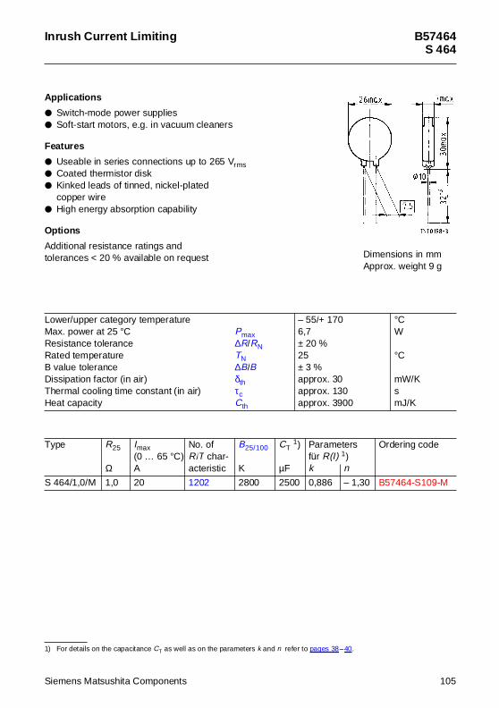
Inrush Current Limiting B57464S 464
App lications
Switch-mode power supplies Soft-start motors, e.g. in vacuum cleaners
Features
Useable in series connections up to 265 Vrms Coated thermistor disk Kinked leads of tinned, nickel-plated
copper wire High energy absorption capability
Options
Additional resistance ratings andtolerances < 20 % available on request
1) For details on the capacitance CT as well as on the parameters k and n refer to pages 38–40.
Lower/upper category temperatureMax. power at 25 °C PmaxResistance tolerance ∆R/RNRated temperature TNB value tolerance ∆B/BDissipation factor (in air) δthThermal cooling time constant (in air) τcHeat capacity Cth
– 55/+ 1706,7± 20 %25± 3 %approx. 30approx. 130approx. 3900
°CW
°C
mW/KsmJ/K
Type R25
Ω
Imax(0 … 65 °C)A
No. ofR/T char-acteristic
B25/100
K
CT 1)
µF
Parametersfür R(I) 1)
Ordering code
k n
S 464/1,0/M 1,0 20 1202 2800 2500 0,886 – 1,30 B57464-S109-M
Dimensions in mmApprox. weight 9 g
Siemens Matsushita Components 105
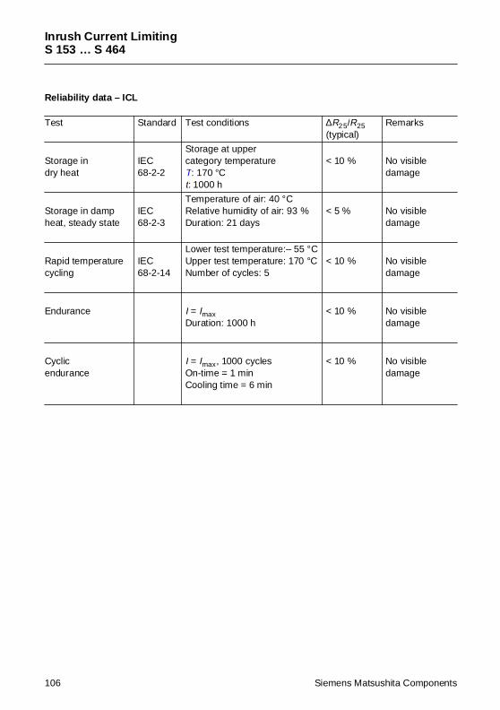
Inrush Current LimitingS 153 … S 464
Reliability data – ICL
Test Standard Test conditions ∆R25/R25(typical)
Remarks
Storage indry heat
IEC68-2-2
Storage at uppercategory temperatureT: 170 °Ct: 1000 h
< 10 % No visibledamage
Storage in dampheat, steady state
IEC68-2-3
Temperature of air: 40 °CRelative humidity of air: 93 %Duration: 21 days
< 5 % No visibledamage
Rapid temperaturecycling
IEC68-2-14
Lower test temperature:– 55 °CUpper test temperature: 170 °CNumber of cycles: 5
< 10 % No visibledamage
Endurance I = ImaxDuration: 1000 h
< 10 % No visibledamage
Cyclicendurance
I = Imax, 1000 cyclesOn-time = 1 minCooling time = 6 min
< 10 % No visibledamage
106 Siemens Matsushita Components
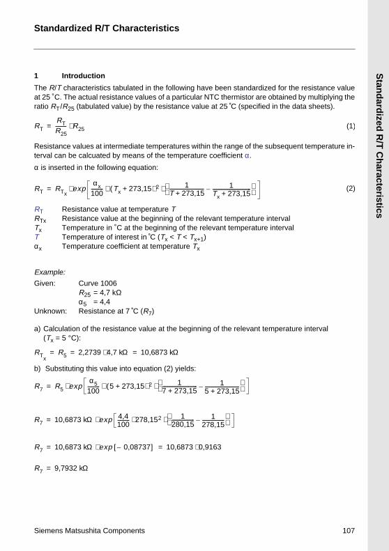
Siemens Matsushita C
1 Introduction
The R/T characteristicsat 25 C. The actual resratio RT/R25 (tabulated
Resistance values at interval can be calcuated
α is inserted in the follo
RT Resistance vaRTx Resistance vaTx Temperature iT Temperature oαx Temperature c
Example:
Given: Curve 10R25 = 4,7α5 = 4,4
Unknown: Resistanc
a) Calculation of the re(Tx = 5 °C):
b) Substituting this val
RT
RTR25--------- R25⋅=
RT RTxexp
αx100---------- ⋅⋅=
RTxR5 2,2739 4⋅= =
R7 R5 expα5
100---------- (⋅⋅=
R7 10,6873 kΩ ex⋅=
R7 10,6873 kΩ ex⋅=
R7 9,7932 kΩ=
Standardized R/T
tabulated in the following have been standardized for the resistance valueistance values of a particular NTC thermistor are obtained by multiplying the value) by the resistance value at 25 C (specified in the data sheets).
termediate temperatures within the range of the subsequent temperature in- by means of the temperature coefficient α.
wing equation:
lue at temperature Tlue at the beginning of the relevant temperature intervaln ˚C at the beginning of the relevant temperature intervalf interest in C (Tx < T < Tx+1)oefficient at temperature Tx
06 kΩ
e at 7 C (R7)
sistance value at the beginning of the relevant temperature interval
ue into equation (2) yields:
(1)
Tx 273,15+( ) 2 1T 273,15+---------------------------- 1
Tx 273,15+-------------------------------–
⋅ (2)
,7 kΩ 10,6873 kΩ=
5 273,15+ ) 2 17 273,15+---------------------------- 1
5 273,15+----------------------------–
⋅
Standardized R
/T C
haracteristics
Characteristics
omponents 107
p 4,4100---------- 278,152 1
280,15------------------ 1
278,15------------------–
⋅ ⋅
p 0,08737–[ ] 10,6873 0,9163⋅=
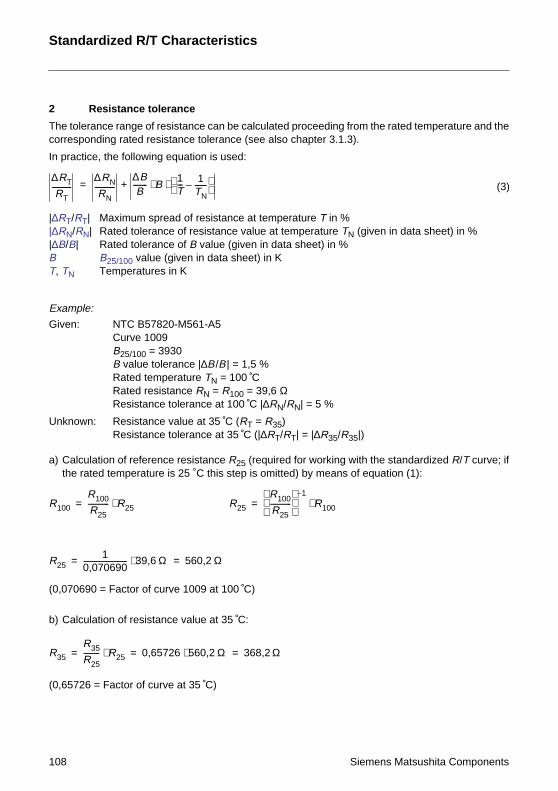
108
2 Resistance tol
The tolerance range ofcorresponding rated re
In practice, the followin
|∆RT/RT| Maximum sp|∆RN/RN| Rated tolera|∆B/B| Rated toleraB B25/100 valuT, TN Temperatur
Example:
Given: NTC B57Curve 10B25/100 =B value tRated temRated resResistanc
Unknown: ResistancResistanc
a) Calculation of referethe rated temperatu
(0,070690 = Factor of c
b) Calculation of resist
(0,65726 = Factor of cu
∆RT
RT-----------
∆RN
RN-----------
∆BB
-------- ⋅+=
R100
R100
R25------------ R25⋅=
R251
0,070690------------------------- 39,6⋅=
R35
R35
R25--------- R25⋅ 0,6= =
Standardized R/T
erance
resistance can be calculated proceeding from the rated temperature and thesistance tolerance (see also chapter 3.1.3).
g equation is used:
read of resistance at temperature T in %nce of resistance value at temperature TN (given in data sheet) in %nce of B value (given in data sheet) in %e (given in data sheet) in Kes in K
820-M561-A509 3930olerance |∆B/B| = 1,5 %
perature TN = 100 Cistance RN = R100 = 39,6 Ωe tolerance at 100 C |∆RN/RN| = 5 %
e value at 35 C (RT = R35)e tolerance at 35 C (|∆RT/RT| = |∆R35/R35|)
nce resistance R25 (required for working with the standardized R/T curve; ifre is 25 ˚C this step is omitted) by means of equation (1):
B1T--- 1
TN-------–
⋅ (3)
R25
R100
R25------------
1–
R100⋅=
Ω 560,2 Ω=
Characteristics
Siemens Matsushita Components
urve 1009 at 100 C)
ance value at 35 C:
rve at 35 C)
5726 560,2 Ω⋅ 368,2 Ω=
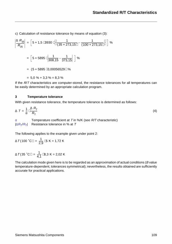
Siemens Matsushita C
c) Calculation of resist
If the R/T characteristibe easily determined b
3 Temperature t
With given resistance t
α Temperatur|∆RT/RT| Resistance
The following applies to
The calculation mode gtemperature-dependenaccurate for practical a
∆ R35
R35--------------- 5 1,5 39⋅+=
5 5895 ⋅+=
5 5895 0⋅+(=
5,0 % + 3,3=
∆ T 1α---
∆ RT
RT-------------⋅=
∆T 100 ˚C( ) 12,9-------- 5⋅=
∆T 35 ˚C( ) 14,1-------- 8,3⋅=
ance tolerance by means of equation (3):
cs are computer-stored, the resistance tolerances for all temperatures cany an appropriate calculation program.
olerance
olerance, the temperature tolerance is determined as follows:
e coefficient at T in %/K (see R/T characteristic) tolerance in % at T
the example given under point 2:
iven here is to be regarded as an approximation of actual conditions (B valuet, tolerances symmetrical); nevertheless, the results obtained are sufficientlypplications.
301
35 273,15+( )-------------------------------------- 1100 273,15+( )-----------------------------------------–
⋅ %
1308,15------------------ 1
373,15------------------– %
,00056529) %
% = 8,3 %
(4)
K = 1,72 K
K = 2,02 K
Standardized R/T Characteristics
omponents 109
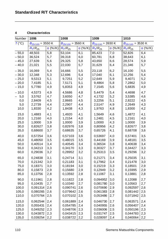
Standardized R/T Characteristics
4 Characteristics
Number 1006 1008 1009 1010
T (°C) B25/100 = 3550 K B25/100 = 3560 K B25/100 = 3930 K B25/100 = 3530 K
RT/R25 α (%/K) RT/R25 α (%/K) RT/R25 α (%/K) RT/R25 α (%/K)
– 55,0– 50,0– 45,0– 40,0
– 35,0– 30,0– 25,0– 20,0– 15,0
– 10,0– 5,0– 0,0– 5,0– 10,0
– 15,0– 20,0– 25,0– 30,0– 35,0
– 40,0– 45,0– 50,0– 55,0– 60,0
– 65,0– 70,0– 75,0– 80,0– 85,0
– 90,0– 95,0 100,0 105,0 110,0
115,0 120,0 125,0 130,0 135,0
48,50336,52427,63921,021
16,06912,348
9,53137,41855,7780
4,53733,57622,84092,27391,8330
1,48831,21601,00000,826270,68600
0,572540,480500,405140,342130,29036
0,248380,213420,183710,158730,13756
0,119610,104350,0913140,0802650,070764
0,0625440,0554310,0492520,0438720,039254
5,85,75,65,5
5,45,35,15,14,9
4,94,74,54,44,2
4,14,03,93,83,7
3,63,53,43,33,2
3,13,03,02,92,8
2,82,72,62,62,5
2,42,42,32,32,2
53,10439,31829,32522,030
16,66612,696
9,72517,51715,8353
4,56863,60502,86652,29071,8438
1,49201,21541,00000,829760,68635
0,571030,480150,405450,341700,28952
0,247140,211830,181940,156800,13592
0,118220,103400,0907410,0796420,070102
0,0618890,0547850,0487060,0434150,038722
6,16,05,85,7
5,55,45,25,14,9
4,84,74,54,44,3
4,14,03,93,83,7
3,63,53,43,33,2
3,13,13,02,92,8
2,82,72,62,62,5
2,42,42,32,32,2
85,42360,78143,65031,629
23,11817,04012,649
9,48647,1545
5,44794,17323,22562,51471,9763
1,56491,24811,00000,809560,65726
0,536970,441690,365340,303270,25313
0,212710,179620,152190,129490,11067
0,0949520,0817800,0706900,0613830,053486
0,0467300,0409550,0360060,0317470,028097
7,06,86,66,4
6,26,15,95,85,6
5,45,25,14,94,8
4,64,54,34,24,1
4,03,93,83,73,5
3,43,43,33,23,1
3,03,02,92,82,7
2,72,62,52,52,4
52,82638,64328,57421,346
16,10012,256
9,40717,28625,6835
4,46983,53852,82222,26491,8300
1,48721,21611,00000,826770,68708
0,574010,481810,406380,344270,29296
0,250350,214780,185010,159950,13881
0,120880,105630,0925970,0814420,071842
0,0635710,0564070,0501960,0447830,040064
6,46,15,95,7
5,55,45,25,04,9
4,74,64,54,34,2
4,14,03,93,83,6
3,53,53,43,33,2
3,13,02,92,92,8
2,72,72,62,52,5
2,42,42,32,32,2
110 Siemens Matsushita Components
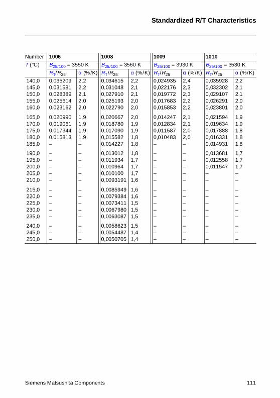
Standardized R/T Characteristics
140,0 145,0 150,0 155,0 160,0
165,0 170,0 175,0 180,0 185,0
190,0 195,0 200,0 205,0 210,0
215,0 220,0 225,0 230,0 235,0
240,0 245,0 250,0
0,0352090,0315810,0283890,0256140,023162
0,0209900,0190610,0173440,015813–
–––––
–––––
–––
2,22,22,12,02,0
1,91,91,91,9–
–––––
–––––
–––
0,0346150,0310480,0279100,0251930,022790
0,0206670,0187800,0170900,0155820,014227
0,0130120,0119340,0109640,0101000,0093191
0,00859490,00793840,00734110,00679800,0063087
0,00586230,00544870,0050705
2,22,12,12,02,0
2,01,91,91,81,8
1,81,71,71,71,6
1,61,61,51,51,5
1,51,41,4
0,0249350,0221760,0197720,0176830,015853
0,0142470,0128340,0115870,010483–
–––––
–––––
–––
2,42,32,32,22,2
2,12,12,02,0–
–––––
–––––
–––
0,0359280,0323020,0291070,0262910,023801
0,0215940,0196340,0178880,0163310,014931
0,0136810,0125580,011547––
–––––
–––
2,22,12,12,02,0
1,91,91,81,81,8
1,71,71,7––
–––––
–––
Number 1006 1008 1009 1010
T (°C) B25/100 = 3550 K B25/100 = 3560 K B25/100 = 3930 K B25/100 = 3530 K
RT/R25 α (%/K) RT/R25 α (%/K) RT/R25 α (%/K) RT/R25 α (%/K)
Siemens Matsushita Components 111
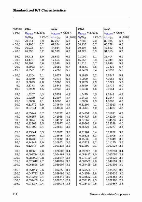
Standardized R/T Characteristics
Number 1011 1012 1013 1014
T (°C) B25/100 = 3730 K B25/100 = 4300 K B25/100 = 3900 K B25/100 = 4250 K
RT/R25 α (%/K) RT/R25 α (%/K) RT/R25 α (%/K) RT/R25 α (%/K)
– 55,0– 50,0– 45,0– 40,0
– 35,0– 30,0– 25,0– 20,0– 15,0
– 10,0– 5,0– 0,0– 5,0– 10,0
– 15,0– 20,0– 25,0– 30,0– 35,0
– 40,0– 45,0– 50,0– 55,0– 60,0
– 65,0– 70,0– 75,0– 80,0– 85,0
– 90,0– 95,0 100,0 105,0 110,0
115,0 120,0 125,0 130,0 135,0
70,01449,90636,01526,296
19,41114,47910,903
8,29236,3591
4,92043,82793,00292,37731,8959
1,52071,22801,00000,817790,67341
0,557470,463570,387400,323680,27200
0,230410,196040,167350,143420,12347
0,106680,0927340,0809030,0706160,061826
0,0542820,0477930,0422490,0374500,033244
6,96,76,46,2
6,05,85,65,45,2
5,14,94,84,64,5
4,34,24,13,93,8
3,73,63,63,53,4
3,33,23,13,03,0
2,82,82,82,72,6
2,62,52,42,42,4
87,23762,26444,85432,599
23,89317,65413,098
9,80597,4266
5,66774,32133,32082,58422,0238
1,58581,25071,00000,796400,64053
0,517720,419580,341720,278770,22861
0,188720,156450,130120,108630,091115
0,0767000,0648670,0550470,0467970,039904
0,0342550,0294980,0254480,0220160,019038
6,86,76,56,3
6,16,05,85,75,5
5,45,35,15,04,9
4,84,74,54,44,3
4,24,14,14,03,9
3,83,73,63,63,5
3,43,33,33,23,1
3,13,03,02,92,8
77,28554,93839,50728,722
21,09915,65211,715
8,85416,7433
5,18154,00993,12832,45691,9438
1,54751,24031,00000,811040,66146
0,542540,447270,370670,308650,25825
0,217070,183230,155350,132230,11302
0,0969510,0834870,0721390,0625590,054425
0,0475080,0415940,0365320,0321750,028423
7,06,76,56,3
6,15,95,75,65,4
5,25,14,94,84,6
4,54,44,34,14,0
3,93,83,73,63,5
3,43,33,33,23,1
3,03,02,92,82,8
2,72,62,62,52,5
83,93560,22843,59331,815
23,40417,34912,946
9,74397,3737
5,62474,30633,32212,57792,0144
1,58481,25471,00000,799130,64287
0,519910,422990,345730,282980,23277
0,192620,160050,133490,111750,093934
0,0792310,0670540,0569320,0485910,041605
0,0356530,0306360,0264540,0229050,019867
6,86,66,46,3
6,16,05,85,75,5
5,45,35,25,04,9
4,84,64,64,44,3
4,24,14,14,03,8
3,83,73,63,53,5
3,43,33,23,13,1
3,13,02,92,92,8
112 Siemens Matsushita Components
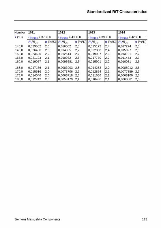
Standardized R/T Characteristics
140,0 145,0 150,0 155,0 160,0
165,0 170,0 175,0 180,0
0,0295820,0264060,0236250,0211930,019057
0,0171760,0155160,0140460,012742
2,32,32,22,12,1
2,12,02,02,0
0,0165020,0143550,0125140,0109320,0095681
0,00839030,00737060,00657180,0058179
2,82,72,72,62,6
2,52,52,52,4
0,0251730,0223580,0199070,0177700,015901
0,0142630,0128240,0115560,010436
2,42,42,32,22,2
2,22,12,12,1
0,0172740,0150270,0131010,0114530,010031
0,00880120,00773590,00681090,0060061
2,82,82,72,72,6
2,62,62,52,5
Number 1011 1012 1013 1014
T (°C) B25/100 = 3730 K B25/100 = 4300 K B25/100 = 3900 K B25/100 = 4250 K
RT/R25 α (%/K) RT/R25 α (%/K) RT/R25 α (%/K) RT/R25 α (%/K)
Siemens Matsushita Components 113
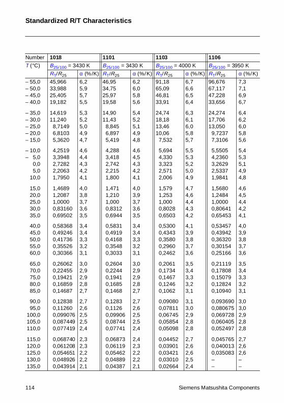
Standardized R/T Characteristics
Number 1018 1101 1103 1106
T (°C) B25/100 = 3430 K B25/100 = 3430 K B25/100 = 4000 K B25/100 = 3950 K
RT/R25 α (%/K) RT/R25 α (%/K) RT/R25 α (%/K) RT/R25 α (%/K)
– 55,0– 50,0– 45,0– 40,0
– 35,0– 30,0– 25,0– 20,0– 15,0
– 10,0– 5,0– 0,0– 5,0– 10,0
– 15,0– 20,0– 25,0– 30,0– 35,0
– 40,0– 45,0– 50,0– 55,0– 60,0
– 65,0– 70,0– 75,0– 80,0– 85,0
– 90,0– 95,0 100,0 105,0 110,0
115,0 120,0 125,0 130,0 135,0
45,96633,98825,40519,182
14,61911,240
8,71496,81035,3620
4,25193,39482,72822,20631,7950
1,46891,20871,00000,831600,69502
0,583680,492460,417360,355260,30366
0,260620,224550,194210,168590,14687
0,128380,112600,0990760,0874490,077419
0,0687400,0612080,0546510,0489260,043914
6,25,95,75,5
5,35,25,04,94,7
4,64,44,34,24,1
4,03,83,73,63,5
3,43,43,33,23,1
3,02,92,92,82,7
2,72,62,52,52,4
2,32,32,22,22,1
46,9534,7525,9719,58
14,9011,43
8,8456,8975,419
4,2883,4182,7422,2151,800
1,4711,2101,0000,83120,6944
0,58310,49190,41680,35480,3033
0,26040,22440,19410,16850,1468
0,12830,11260,099060,087440,07741
0,068730,061190,054620,048890,04387
6,26,05,85,6
5,45,25,14,94,8
4,64,54,34,24,1
4,03,93,73,63,5
3,43,43,33,23,1
3,02,92,92,82,7
2,72,62,52,52,4
2,42,32,22,22,1
91,1865,0946,8133,91
24,7418,1813,4610,06
7,532
5,6944,3303,3232,5712,006
1,5791,2531,0000,80280,6503
0,53000,43430,35800,29600,2462
0,20610,17340,14670,12460,1062
0,090800,078110,067450,058540,05098
0,044520,039010,034210,030100,02664
6,76,66,56,4
6,36,16,05,85,7
5,55,35,25,04,9
4,74,64,44,34,2
4,13,93,83,73,6
3,53,43,33,23,1
3,13,02,92,82,8
2,72,62,62,52,4
96,67667,11747,22833,656
24,27417,70613,050
9,72377,3106
5,55054,23603,26292,53371,9841
1,56801,24841,00000,806410,65453
0,534570,439420,363200,301540,25166
0,211190,178080,150790,128240,10940
0,0936900,0806750,0697280,0604050,052497
0,0457650,0400130,035083––
7,37,16,96,7
6,46,26,05,85,6
5,45,35,14,94,8
4,64,54,44,24,1
4,03,93,83,73,6
3,53,43,33,23,1
3,03,02,92,82,8
2,72,62,6––
114 Siemens Matsushita Components
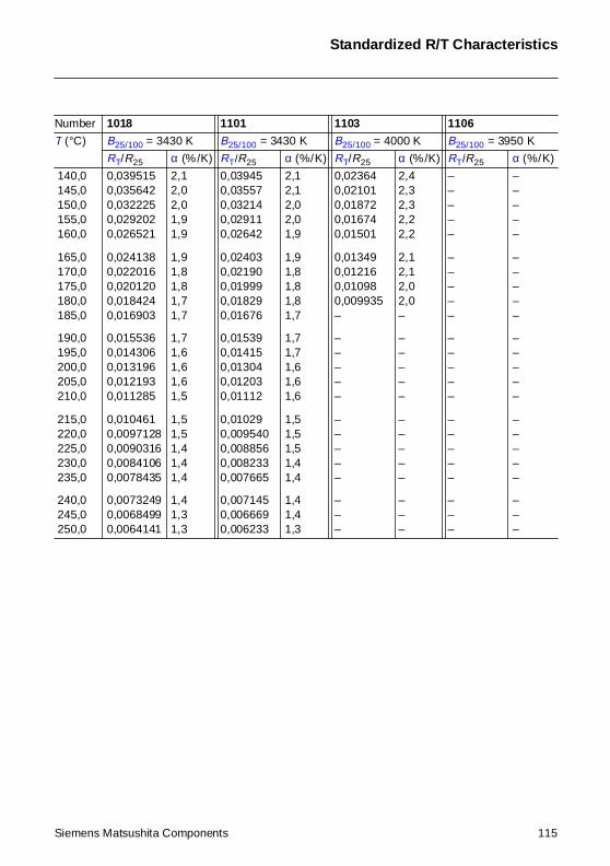
Standardized R/T Characteristics
140,0 145,0 150,0 155,0 160,0
165,0 170,0 175,0 180,0 185,0
190,0 195,0 200,0 205,0 210,0
215,0 220,0 225,0 230,0 235,0
240,0 245,0 250,0
0,0395150,0356420,0322250,0292020,026521
0,0241380,0220160,0201200,0184240,016903
0,0155360,0143060,0131960,0121930,011285
0,0104610,00971280,00903160,00841060,0078435
0,00732490,00684990,0064141
2,12,02,01,91,9
1,91,81,81,71,7
1,71,61,61,61,5
1,51,51,41,41,4
1,41,31,3
0,039450,035570,032140,029110,02642
0,024030,021900,019990,018290,01676
0,015390,014150,013040,012030,01112
0,010290,0095400,0088560,0082330,007665
0,0071450,0066690,006233
2,12,12,02,01,9
1,91,81,81,81,7
1,71,71,61,61,6
1,51,51,51,41,4
1,41,41,3
0,023640,021010,018720,016740,01501
0,013490,012160,010980,009935–
–––––
–––––
–––
2,42,32,32,22,2
2,12,12,02,0–
–––––
–––––
–––
–––––
–––––
–––––
–––––
–––
–––––
–––––
–––––
–––––
–––
Number 1018 1101 1103 1106
T (°C) B25/100 = 3430 K B25/100 = 3430 K B25/100 = 4000 K B25/100 = 3950 K
RT/R25 α (%/K) RT/R25 α (%/K) RT/R25 α (%/K) RT/R25 α (%/K)
Siemens Matsushita Components 115
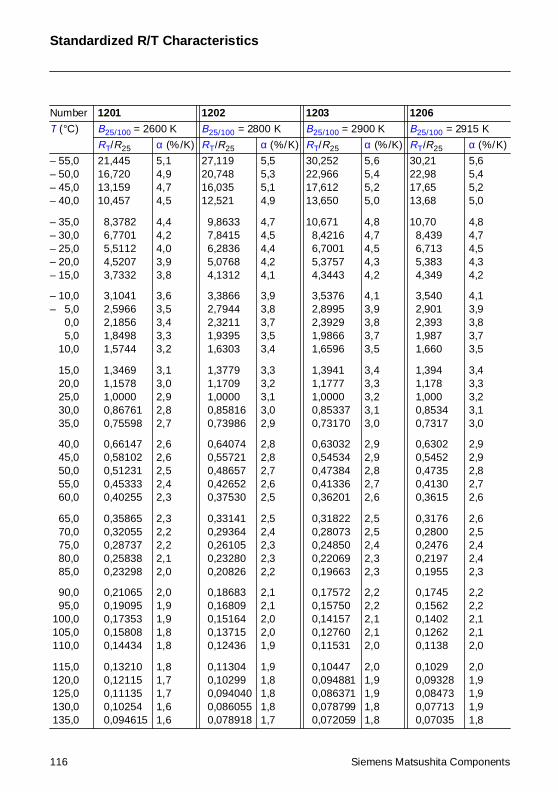
Standardized R/T Characteristics
Number 1201 1202 1203 1206
T (°C) B25/100 = 2600 K B25/100 = 2800 K B25/100 = 2900 K B25/100 = 2915 K
RT/R25 α (%/K) RT/R25 α (%/K) RT/R25 α (%/K) RT/R25 α (%/K)
– 55,0– 50,0– 45,0– 40,0
– 35,0– 30,0– 25,0– 20,0– 15,0
– 10,0– 5,0– 0,0– 5,0– 10,0
– 15,0– 20,0– 25,0– 30,0– 35,0
– 40,0– 45,0– 50,0– 55,0– 60,0
– 65,0– 70,0– 75,0– 80,0– 85,0
– 90,0– 95,0 100,0 105,0 110,0
115,0 120,0 125,0 130,0 135,0
21,44516,72013,15910,457
8,37826,77015,51124,52073,7332
3,10412,59662,18561,84981,5744
1,34691,15781,00000,867610,75598
0,661470,581020,512310,453330,40255
0,358650,320550,287370,258380,23298
0,210650,190950,173530,158080,14434
0,132100,121150,111350,102540,094615
5,14,94,74,5
4,44,24,03,93,8
3,63,53,43,33,2
3,13,02,92,82,7
2,62,62,52,42,3
2,32,22,22,12,0
2,01,91,91,81,8
1,81,71,71,61,6
27,11920,74816,03512,521
9,86337,84156,28365,07684,1312
3,38662,79442,32111,93951,6303
1,37791,17091,00000,858160,73986
0,640740,557210,486570,426520,37530
0,331410,293640,261050,232800,20826
0,186830,168090,151640,137150,12436
0,113040,102990,0940400,0860550,078918
5,55,35,14,9
4,74,54,44,24,1
3,93,83,73,53,4
3,33,23,13,02,9
2,82,82,72,62,5
2,52,42,32,32,2
2,12,12,02,01,9
1,91,81,81,81,7
30,25222,96617,61213,650
10,6718,42166,70015,37574,3443
3,53762,89952,39291,98661,6596
1,39411,17771,00000,853370,73170
0,630320,545340,473840,413360,36201
0,318220,280730,248500,220690,19663
0,175720,157500,141570,127600,11531
0,104470,0948810,0863710,0787990,072059
5,65,45,25,0
4,84,74,54,34,2
4,13,93,83,73,5
3,43,33,23,13,0
2,92,92,82,72,6
2,52,52,42,32,3
2,22,22,12,12,0
2,01,91,91,81,8
30,2122,9817,6513,68
10,708,4396,7135,3834,349
3,5402,9012,3931,9871,660
1,3941,1781,0000,85340,7317
0,63020,54520,47350,41300,3615
0,31760,28000,24760,21970,1955
0,17450,15620,14020,12620,1138
0,10290,093280,084730,077130,07035
5,65,45,25,0
4,84,74,54,34,2
4,13,93,83,73,5
3,43,33,23,13,0
2,92,92,82,72,6
2,62,52,42,42,3
2,22,22,12,12,0
2,01,91,91,91,8
116 Siemens Matsushita Components
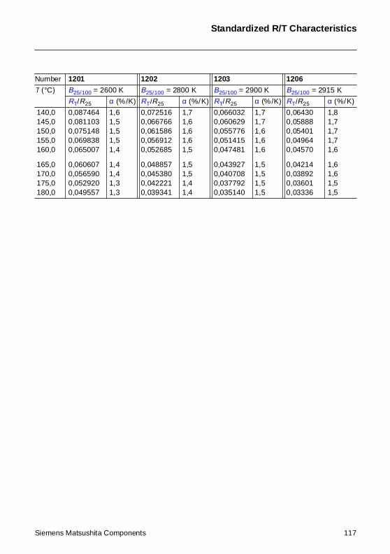
Standardized R/T Characteristics
140,0 145,0 150,0 155,0 160,0
165,0 170,0 175,0 180,0
0,0874640,0811030,0751480,0698380,065007
0,0606070,0565900,0529200,049557
1,61,51,51,51,4
1,41,41,31,3
0,0725160,0667660,0615860,0569120,052685
0,0488570,0453800,0422210,039341
1,71,61,61,61,5
1,51,51,41,4
0,0660320,0606290,0557760,0514150,047481
0,0439270,0407080,0377920,035140
1,71,71,61,61,6
1,51,51,51,5
0,064300,058880,054010,049640,04570
0,042140,038920,036010,03336
1,81,71,71,71,6
1,61,61,51,5
Number 1201 1202 1203 1206
T (°C) B25/100 = 2600 K B25/100 = 2800 K B25/100 = 2900 K B25/100 = 2915 K
RT/R25 α (%/K) RT/R25 α (%/K) RT/R25 α (%/K) RT/R25 α (%/K)
Siemens Matsushita Components 117
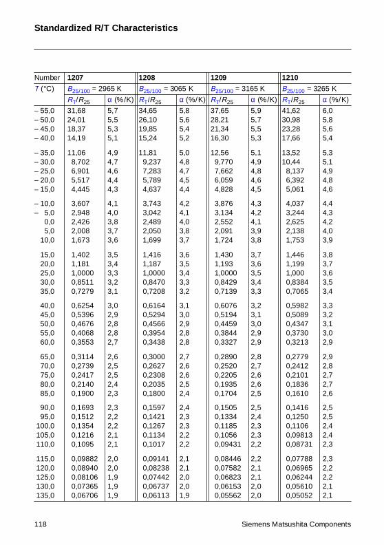
Standardized R/T Characteristics
Number 1207 1208 1209 1210
T (°C) B25/100 = 2965 K B25/100 = 3065 K B25/100 = 3165 K B25/100 = 3265 K
RT/R25 α (%/K) RT/R25 α (%/K) RT/R25 α (%/K) RT/R25 α (%/K)
– 55,0– 50,0– 45,0– 40,0
– 35,0– 30,0– 25,0– 20,0– 15,0
– 10,0– 5,0– 0,0– 5,0– 10,0
– 15,0– 20,0– 25,0– 30,0– 35,0
– 40,0– 45,0– 50,0– 55,0– 60,0
– 65,0– 70,0– 75,0– 80,0– 85,0
– 90,0– 95,0 100,0 105,0 110,0
115,0 120,0 125,0 130,0 135,0
31,6824,0118,3714,19
11,068,7026,9015,5174,445
3,6072,9482,4262,0081,673
1,4021,1811,00000,85110,7279
0,62540,53960,46760,40680,3553
0,31140,27390,24170,21400,1900
0,16930,15120,13540,12160,1095
0,098820,089400,081060,073650,06706
5,75,55,35,1
4,94,74,64,44,3
4,14,03,83,73,6
3,53,43,33,23,1
3,02,92,82,82,7
2,62,52,52,42,3
2,32,22,22,12,1
2,02,01,91,91,9
34,6526,1019,8515,24
11,819,2377,2835,7894,637
3,7433,0422,4892,0501,699
1,4161,1871,00000,84700,7208
0,61640,52940,45660,39540,3438
0,30000,26270,23080,20350,1800
0,15970,14210,12670,11340,1017
0,091410,082380,074420,067370,06113
5,85,65,45,2
5,04,84,74,54,4
4,24,14,03,83,7
3,63,53,43,33,2
3,13,02,92,82,8
2,72,62,62,52,4
2,42,32,32,22,2
2,12,12,02,01,9
37,6528,2121,3416,30
12,569,7707,6626,0594,828
3,8763,1342,5522,0911,724
1,4301,1931,00000,84290,7139
0,60760,51940,44590,38440,3327
0,28900,25200,22050,19350,1704
0,15050,13340,11850,10560,09431
0,084460,075820,068230,061530,05562
5,95,75,55,3
5,14,94,84,64,5
4,34,24,13,93,8
3,73,63,53,43,3
3,23,13,02,92,9
2,82,72,62,62,5
2,52,42,32,32,2
2,22,12,12,02,0
41,6230,9823,2817,66
13,5210,44
8,1376,3925,061
4,0373,2442,6252,1381,753
1,4461,1991,0000,83840,7065
0,59820,50890,43470,37300,3213
0,27790,24120,21010,18360,1610
0,14160,12500,11060,098130,08731
0,077880,069650,062440,056100,05052
6,05,85,65,4
5,35,14,94,84,6
4,44,34,24,03,9
3,83,73,63,53,4
3,33,23,13,02,9
2,92,82,72,72,6
2,52,52,42,42,3
2,32,22,22,12,1
118 Siemens Matsushita Components

Standardized R/T Characteristics
140,0 145,0 150,0 155,0 160,0
165,0 170,0 175,0 180,0
0,061190,055940,051240,047020,04322
0,039790,036700,033910,03137
1,81,81,71,71,7
1,61,61,61,5
0,055570,050630,046210,042260,03871
0,035530,032660,030070,02773
1,91,81,81,81,7
1,71,71,61,6
0,050380,045730,041590,037900,03460
0,031640,028990,026600,02445
2,01,91,91,81,8
1,81,71,71,7
0,045600,041240,037370,033930,03087
0,028140,025690,023490,02152
2,02,02,01,91,9
1,81,81,81,7
Number 1207 1208 1209 1210
T (°C) B25/100 = 2965 K B25/100 = 3065 K B25/100 = 3165 K B25/100 = 3265 K
RT/R25 α (%/K) RT/R25 α (%/K) RT/R25 α (%/K) RT/R25 α (%/K)
Siemens Matsushita Components 119
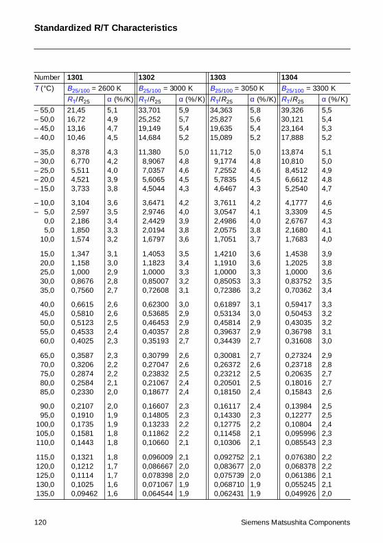
Standardized R/T Characteristics
Number 1301 1302 1303 1304
T (°C) B25/100 = 2600 K B25/100 = 3000 K B25/100 = 3050 K B25/100 = 3300 K
RT/R25 α (%/K) RT/R25 α (%/K) RT/R25 α (%/K) RT/R25 α (%/K)
– 55,0– 50,0– 45,0– 40,0
– 35,0– 30,0– 25,0– 20,0– 15,0
– 10,0– 5,0– 0,0– 5,0– 10,0
– 15,0– 20,0– 25,0– 30,0– 35,0
– 40,0– 45,0– 50,0– 55,0– 60,0
– 65,0– 70,0– 75,0– 80,0– 85,0
– 90,0– 95,0 100,0 105,0 110,0
115,0 120,0 125,0 130,0 135,0
21,4516,7213,1610,46
8,3786,7705,5114,5213,733
3,1042,5972,1861,8501,574
1,3471,1581,0000,86760,7560
0,66150,58100,51230,45330,4025
0,35870,32060,28740,25840,2330
0,21070,19100,17350,15810,1443
0,13210,12120,11140,10250,09462
5,14,94,74,5
4,34,24,03,93,8
3,63,53,43,33,2
3,13,02,92,82,7
2,62,62,52,42,3
2,32,22,22,12,0
2,01,91,91,81,8
1,81,71,71,61,6
33,70125,25219,14914,684
11,3808,90677,03575,60654,5044
3,64712,97462,44292,01941,6797
1,40531,18231,00000,850070,72608
0,623000,536850,464530,403570,35193
0,307990,270470,238320,210670,18677
0,166070,148050,132330,118620,10660
0,0960090,0866670,0783980,0710670,064544
5,95,75,45,2
5,04,84,64,54,3
4,24,03,93,83,6
3,53,43,33,23,1
3,02,92,92,82,7
2,62,62,52,42,4
2,32,32,22,22,1
2,12,02,01,91,9
34,36325,82719,63515,089
11,7129,17747,25525,78354,6467
3,76113,05472,49862,05751,7051
1,42101,19101,00000,850530,72386
0,618970,531340,458140,396370,34439
0,300810,263720,232120,205010,18150
0,161170,143300,127750,114580,10306
0,0927520,0836770,0757390,0687100,062431
5,85,65,45,2
5,04,84,64,54,3
4,24,14,03,83,7
3,63,63,33,33,2
3,13,02,92,92,7
2,72,62,52,52,4
2,42,32,22,12,1
2,12,02,01,91,9
39,32630,12123,16417,888
13,87410,810
8,45126,66125,2540
4,17773,33092,67672,16801,7683
1,45381,20251,00000,837520,70362
0,594170,504530,430350,367980,31608
0,273240,237180,206350,180160,15843
0,139840,122770,108040,0959960,085543
0,0763800,0683780,0613860,0552450,049926
5,55,45,35,2
5,15,04,94,84,7
4,64,54,34,14,0
3,93,83,63,53,4
3,33,23,23,13,0
2,92,82,72,72,6
2,52,52,42,32,3
2,22,22,12,12,0
120 Siemens Matsushita Components
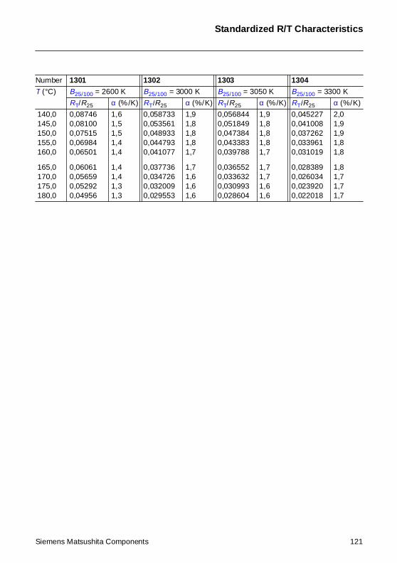
Standardized R/T Characteristics
140,0 145,0 150,0 155,0 160,0
165,0 170,0 175,0 180,0
0,087460,081000,075150,069840,06501
0,060610,056590,052920,04956
1,61,51,51,41,4
1,41,41,31,3
0,0587330,0535610,0489330,0447930,041077
0,0377360,0347260,0320090,029553
1,91,81,81,81,7
1,71,61,61,6
0,0568440,0518490,0473840,0433830,039788
0,0365520,0336320,0309930,028604
1,91,81,81,81,7
1,71,71,61,6
0,0452270,0410080,0372620,0339610,031019
0,0283890,0260340,0239200,022018
2,01,91,91,81,8
1,81,71,71,7
Number 1301 1302 1303 1304
T (°C) B25/100 = 2600 K B25/100 = 3000 K B25/100 = 3050 K B25/100 = 3300 K
RT/R25 α (%/K) RT/R25 α (%/K) RT/R25 α (%/K) RT/R25 α (%/K)
Siemens Matsushita Components 121
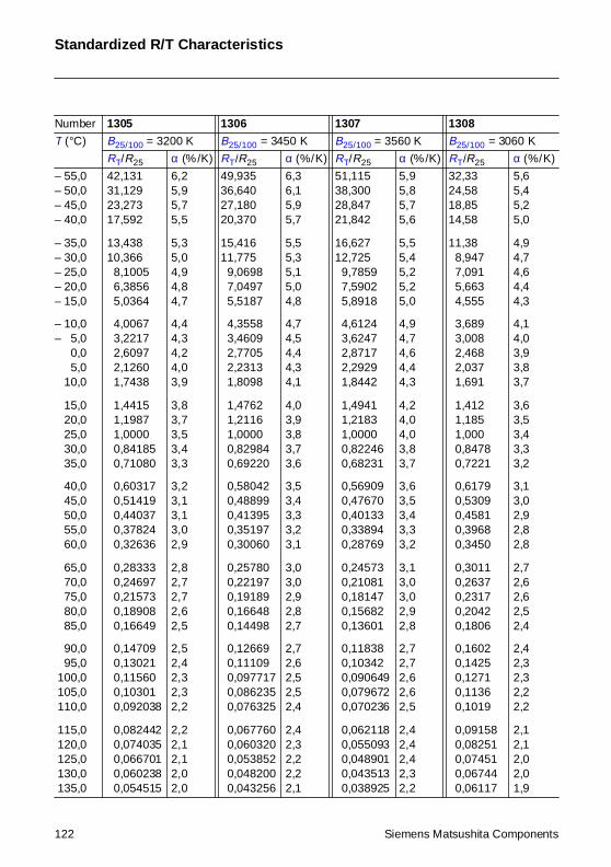
Standardized R/T Characteristics
Number 1305 1306 1307 1308
T (°C) B25/100 = 3200 K B25/100 = 3450 K B25/100 = 3560 K B25/100 = 3060 K
RT/R25 α (%/K) RT/R25 α (%/K) RT/R25 α (%/K) RT/R25 α (%/K)
– 55,0– 50,0– 45,0– 40,0
– 35,0– 30,0– 25,0– 20,0– 15,0
– 10,0– 5,0– 0,0– 5,0– 10,0
– 15,0– 20,0– 25,0– 30,0– 35,0
– 40,0– 45,0– 50,0– 55,0– 60,0
– 65,0– 70,0– 75,0– 80,0– 85,0
– 90,0– 95,0 100,0 105,0 110,0
115,0 120,0 125,0 130,0 135,0
42,13131,12923,27317,592
13,43810,366
8,10056,38565,0364
4,00673,22172,60972,12601,7438
1,44151,19871,00000,841850,71080
0,603170,514190,440370,378240,32636
0,283330,246970,215730,189080,16649
0,147090,130210,115600,103010,092038
0,0824420,0740350,0667010,0602380,054515
6,25,95,75,5
5,35,04,94,84,7
4,44,34,24,03,9
3,83,73,53,43,3
3,23,13,13,02,9
2,82,72,72,62,5
2,52,42,32,32,2
2,22,12,12,02,0
49,93536,64027,18020,370
15,41611,775
9,06987,04975,5187
4,35583,46092,77052,23131,8098
1,47621,21161,00000,829840,69220
0,580420,488990,413950,351970,30060
0,257800,221970,191890,166480,14498
0,126690,111090,0977170,0862350,076325
0,0677600,0603200,0538520,0482000,043256
6,36,15,95,7
5,55,35,15,04,8
4,74,54,44,34,1
4,03,93,83,73,6
3,53,43,33,23,1
3,03,02,92,82,7
2,72,62,52,52,4
2,42,32,22,22,1
51,11538,30028,84721,842
16,62712,725
9,78597,59025,8918
4,61243,62472,87172,29291,8442
1,49411,21831,00000,822460,68231
0,569090,476700,401330,338940,28769
0,245730,210810,181470,156820,13601
0,118380,103420,0906490,0796720,070236
0,0621180,0550930,0489010,0435130,038925
5,95,85,75,6
5,55,45,25,25,0
4,94,74,64,44,3
4,24,04,03,83,7
3,63,53,43,33,2
3,13,03,02,92,8
2,72,72,62,62,5
2,42,42,42,32,2
32,3324,5818,8514,58
11,388,9477,0915,6634,555
3,6893,0082,4682,0371,691
1,4121,1851,0000,84780,7221
0,61790,53090,45810,39680,3450
0,30110,26370,23170,20420,1806
0,16020,14250,12710,11360,1019
0,091580,082510,074510,067440,06117
5,65,45,25,0
4,94,74,64,44,3
4,14,03,93,83,7
3,63,53,43,33,2
3,13,02,92,82,8
2,72,62,62,52,4
2,42,32,32,22,2
2,12,12,02,01,9
122 Siemens Matsushita Components
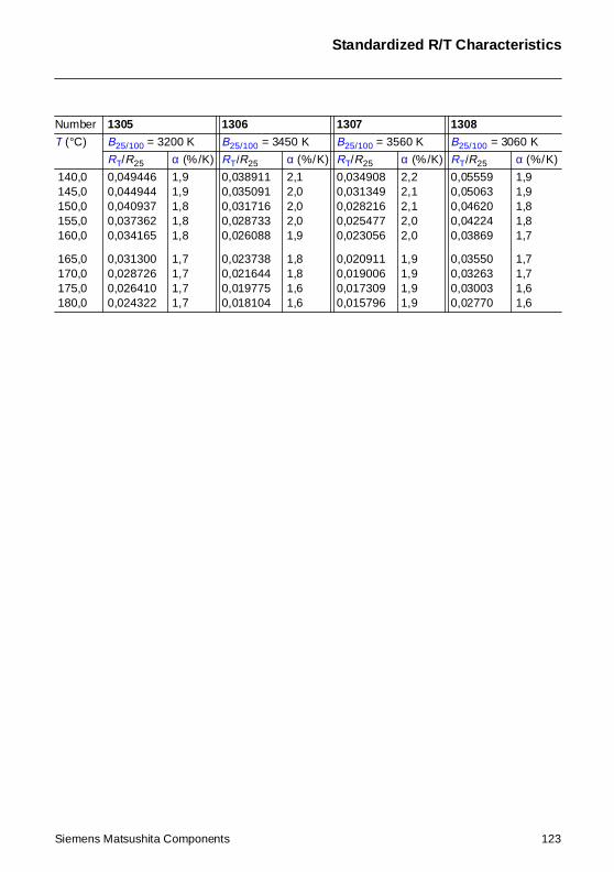
Standardized R/T Characteristics
140,0 145,0 150,0 155,0 160,0
165,0 170,0 175,0 180,0
0,0494460,0449440,0409370,0373620,034165
0,0313000,0287260,0264100,024322
1,91,91,81,81,8
1,71,71,71,7
0,0389110,0350910,0317160,0287330,026088
0,0237380,0216440,0197750,018104
2,12,02,02,01,9
1,81,81,61,6
0,0349080,0313490,0282160,0254770,023056
0,0209110,0190060,0173090,015796
2,22,12,12,02,0
1,91,91,91,9
0,055590,050630,046200,042240,03869
0,035500,032630,030030,02770
1,91,91,81,81,7
1,71,71,61,6
Number 1305 1306 1307 1308
T (°C) B25/100 = 3200 K B25/100 = 3450 K B25/100 = 3560 K B25/100 = 3060 K
RT/R25 α (%/K) RT/R25 α (%/K) RT/R25 α (%/K) RT/R25 α (%/K)
Siemens Matsushita Components 123
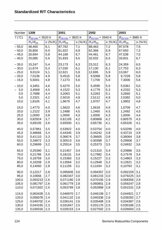
Standardized R/T Characteristics
Number 1309 2001 2002 2003
T (°C) B25/100 = 3520 K B25/100 = 3920 K B25/100 = 3940 K B25/100 = 3980 K
RT/R25 α (%/K) RT/R25 α (%/K) RT/R25 α (%/K) RT/R25 α (%/K)
– 55,0– 50,0– 45,0– 40,0
– 35,0– 30,0– 25,0– 20,0– 15,0
– 10,0– 5,0– 0,0– 5,0– 10,0
– 15,0– 20,0– 25,0– 30,0– 35,0
– 40,0– 45,0– 50,0– 55,0– 60,0
– 65,0– 70,0– 75,0– 80,0– 85,0
– 90,0– 95,0 100,0 105,0 110,0
115,0 120,0 125,0 130,0 135,0
48,46035,80026,69420,085
15,24711,674
9,01247,01365,5001
4,34513,45692,76882,23211,8105
1,47731,21221,00000,829240,69105
0,578610,486660,411100,348720,29699
0,253900,217860,187590,162080,14050
0,122170,106560,0932130,0817670,071922
0,0634280,0560780,0497020,0441550,039316
6,16,05,85,6
5,45,35,14,94,8
4,64,54,44,24,1
4,03,93,83,73,6
3,53,43,33,33,2
3,13,03,02,92,8
2,82,72,62,62,5
2,52,42,42,32,3
87,76261,92244,16831,833
23,17317,03012,621
9,45157,1273
5,42704,15223,20632,50191,9679
1,56231,24881,00000,811050,65930
0,539220,443450,366740,305130,25514
0,214570,181310,153600,130640,11155
0,0956060,0823470,0711800,0617790,053799
0,0469700,0411320,0361410,0318470,028153
7,16,96,76,5
6,36,15,95,85,6
5,55,35,14,94,7
4,64,54,34,24,1
4,03,93,73,63,5
3,43,43,33,23,1
3,03,02,92,82,8
2,72,62,62,52,4
88,46362,36844,46132,032
23,31217,13012,695
9,50687,1700
5,45954,17793,22632,51121,9707
1,56181,24651,00000,808680,65735
0,537540,442420,366050,303980,25373
0,213100,179820,152270,129480,11034
0,0943570,0812150,0701550,0608010,052869
0,0461090,0403360,0354080,0311700,027502
7,26,96,76,5
6,36,15,95,85,6
5,55,35,14,94,7
4,64,54,34,24,1
4,03,83,83,73,5
3,43,43,33,23,2
3,03,02,92,82,8
2,72,62,62,52,5
97,57867,65047,53833,831
24,35917,75313,067
9,72287,3006
5,53614,23323,26602,53921,9902
1,57091,24921,00000,805750,65326
0,532900,437150,360640,299080,24932
0,208860,175780,148630,126210,10763
0,0921590,0792250,0683560,0592470,051531
0,0449210,0392820,0343870,0301860,026650
7,57,27,06,7
6,56,36,05,85,6
5,55,35,15,04,8
4,74,54,44,34,1
4,03,93,83,73,6
3,53,43,33,23,1
3,13,02,92,82,8
2,72,72,62,52,5
124 Siemens Matsushita Components
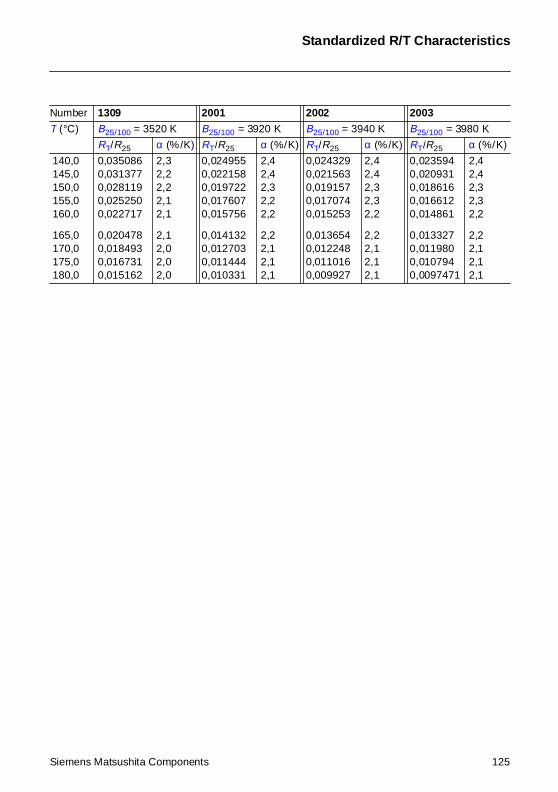
Standardized R/T Characteristics
140,0 145,0 150,0 155,0 160,0
165,0 170,0 175,0 180,0
0,0350860,0313770,0281190,0252500,022717
0,0204780,0184930,0167310,015162
2,32,22,22,12,1
2,12,02,02,0
0,0249550,0221580,0197220,0176070,015756
0,0141320,0127030,0114440,010331
2,42,42,32,22,2
2,22,12,12,1
0,0243290,0215630,0191570,0170740,015253
0,0136540,0122480,0110160,009927
2,42,42,32,32,2
2,22,12,12,1
0,0235940,0209310,0186160,0166120,014861
0,0133270,0119800,0107940,0097471
2,42,42,32,32,2
2,22,12,12,1
Number 1309 2001 2002 2003
T (°C) B25/100 = 3520 K B25/100 = 3920 K B25/100 = 3940 K B25/100 = 3980 K
RT/R25 α (%/K) RT/R25 α (%/K) RT/R25 α (%/K) RT/R25 α (%/K)
Siemens Matsushita Components 125
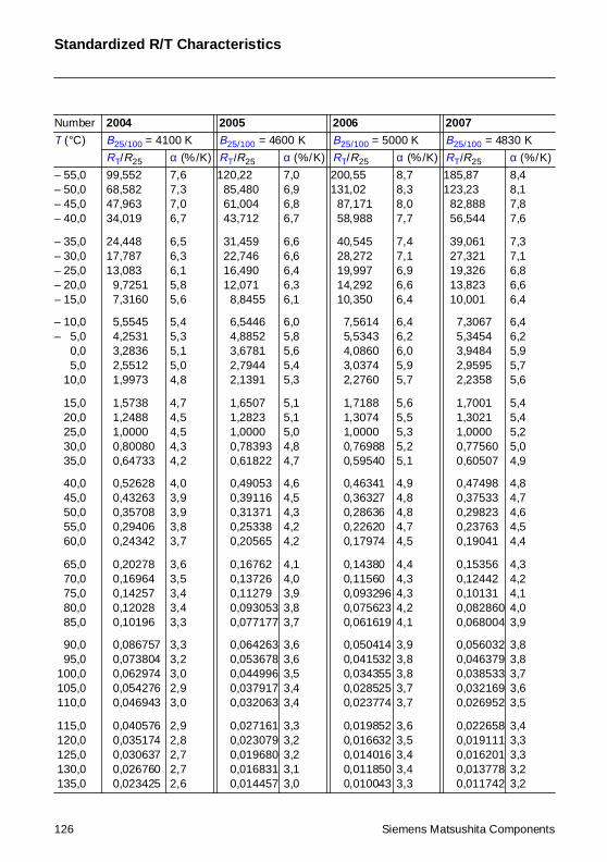
Standardized R/T Characteristics
Number 2004 2005 2006 2007
T (°C) B25/100 = 4100 K B25/100 = 4600 K B25/100 = 5000 K B25/100 = 4830 K
RT/R25 α (%/K) RT/R25 α (%/K) RT/R25 α (%/K) RT/R25 α (%/K)
– 55,0– 50,0– 45,0– 40,0
– 35,0– 30,0– 25,0– 20,0– 15,0
– 10,0– 5,0– 0,0– 5,0– 10,0
– 15,0– 20,0– 25,0– 30,0– 35,0
– 40,0– 45,0– 50,0– 55,0– 60,0
– 65,0– 70,0– 75,0– 80,0– 85,0
– 90,0– 95,0 100,0 105,0 110,0
115,0 120,0 125,0 130,0 135,0
99,55268,58247,96334,019
24,44817,78713,083
9,72517,3160
5,55454,25313,28362,55121,9973
1,57381,24881,00000,800800,64733
0,526280,432630,357080,294060,24342
0,202780,169640,142570,120280,10196
0,0867570,0738040,0629740,0542760,046943
0,0405760,0351740,0306370,0267600,023425
7,67,37,06,7
6,56,36,15,85,6
5,45,35,15,04,8
4,74,54,54,34,2
4,03,93,93,83,7
3,63,53,43,43,3
3,33,23,02,93,0
2,92,82,72,72,6
120,2285,48061,00443,712
31,45922,74616,49012,071
8,8455
6,54464,88523,67812,79442,1391
1,65071,28231,00000,783930,61822
0,490530,391160,313710,253380,20565
0,167620,137260,112790,0930530,077177
0,0642630,0536780,0449960,0379170,032063
0,0271610,0230790,0196800,0168310,014457
7,06,96,86,7
6,66,66,46,36,1
6,05,85,65,45,3
5,15,15,04,84,7
4,64,54,34,24,2
4,14,03,93,83,7
3,63,63,53,43,4
3,33,23,23,13,0
200,55131,02
87,17158,988
40,54528,27219,99714,29210,350
7,56145,53434,08603,03742,2760
1,71881,30741,00000,769880,59540
0,463410,363270,286360,226200,17974
0,143800,115600,0932960,0756230,061619
0,0504140,0415320,0343550,0285250,023774
0,0198520,0166320,0140160,0118500,010043
8,78,38,07,7
7,47,16,96,66,4
6,46,26,05,95,7
5,65,55,35,25,1
4,94,84,84,74,5
4,44,34,34,24,1
3,93,83,83,73,7
3,63,53,43,43,3
185,87123,23
82,88856,544
39,06127,32119,32613,82310,001
7,30675,34543,94842,95952,2358
1,70011,30211,00000,775600,60507
0,474980,375330,298230,237630,19041
0,153560,124420,101310,0828600,068004
0,0560320,0463790,0385330,0321690,026952
0,0226580,0191110,0162010,0137780,011742
8,48,17,87,6
7,37,16,86,66,4
6,46,25,95,75,6
5,45,45,25,04,9
4,84,74,64,54,4
4,34,24,14,03,9
3,83,83,73,63,5
3,43,33,33,23,2
126 Siemens Matsushita Components
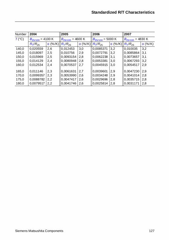
Standardized R/T Characteristics
140,0 145,0 150,0 155,0 160,0
165,0 170,0 175,0 180,0
0,0205590,0180970,0159690,0141290,012534
0,0111460,00993570,00887820,0079517
2,62,52,52,42,4
2,32,32,22,2
0,0124530,0107560,00931540,00809480,0070537
0,00616310,00539900,00474170,0041746
3,02,92,82,82,7
2,72,62,62,6
0,00853710,00727910,00622380,00533810,0045915
0,00396010,00342480,00296960,0025814
3,23,23,13,03,0
2,92,92,82,8
0,0100350,00858640,00736570,00672930,0054517
0,00472300,00410140,00357150,0031171
3,23,13,13,22,9
2,92,82,82,8
Number 2004 2005 2006 2007
T (°C) B25/100 = 4100 K B25/100 = 4600 K B25/100 = 5000 K B25/100 = 4830 K
RT/R25 α (%/K) RT/R25 α (%/K) RT/R25 α (%/K) RT/R25 α (%/K)
Siemens Matsushita Components 127
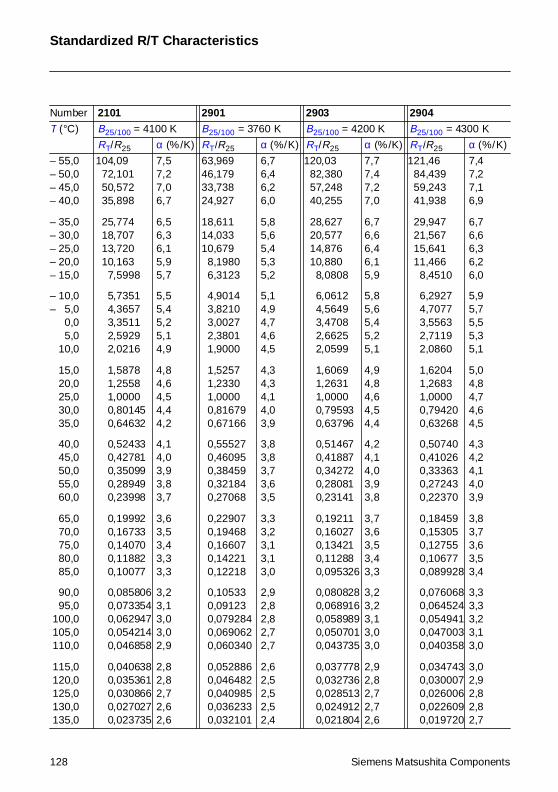
Standardized R/T Characteristics
Number 2101 2901 2903 2904
T (°C) B25/100 = 4100 K B25/100 = 3760 K B25/100 = 4200 K B25/100 = 4300 K
RT/R25 α (%/K) RT/R25 α (%/K) RT/R25 α (%/K) RT/R25 α (%/K)
– 55,0– 50,0– 45,0– 40,0
– 35,0– 30,0– 25,0– 20,0– 15,0
– 10,0– 5,0– 0,0– 5,0– 10,0
– 15,0– 20,0– 25,0– 30,0– 35,0
– 40,0– 45,0– 50,0– 55,0– 60,0
– 65,0– 70,0– 75,0– 80,0– 85,0
– 90,0– 95,0 100,0 105,0 110,0
115,0 120,0 125,0 130,0 135,0
104,0972,10150,57235,898
25,77418,70713,72010,163
7,5998
5,73514,36573,35112,59292,0216
1,58781,25581,00000,801450,64632
0,524330,427810,350990,289490,23998
0,199920,167330,140700,118820,10077
0,0858060,0733540,0629470,0542140,046858
0,0406380,0353610,0308660,0270270,023735
7,57,27,06,7
6,56,36,15,95,7
5,55,45,25,14,9
4,84,64,54,44,2
4,14,03,93,83,7
3,63,53,43,33,3
3,23,13,03,02,9
2,82,82,72,62,6
63,96946,17933,73824,927
18,61114,03310,679
8,19806,3123
4,90143,82103,00272,38011,9000
1,52571,23301,00000,816790,67166
0,555270,460950,384590,321840,27068
0,229070,194680,166070,142210,12218
0,105330,091230,0792840,0690620,060340
0,0528860,0464820,0409850,0362330,032101
6,76,46,26,0
5,85,65,45,35,2
5,14,94,74,64,5
4,34,34,14,03,9
3,83,83,73,63,5
3,33,23,13,13,0
2,92,82,82,72,7
2,62,52,52,52,4
120,0382,38057,24840,255
28,62720,57714,87610,880
8,0808
6,06124,56493,47082,66252,0599
1,60691,26311,00000,795930,63796
0,514670,418870,342720,280810,23141
0,192110,160270,134210,112880,095326
0,0808280,0689160,0589890,0507010,043735
0,0377780,0327360,0285130,0249120,021804
7,77,47,27,0
6,76,66,46,15,9
5,85,65,45,25,1
4,94,84,64,54,4
4,24,14,03,93,8
3,73,63,53,43,3
3,23,23,13,03,0
2,92,82,72,72,6
121,4684,43959,24341,938
29,94721,56715,64111,466
8,4510
6,29274,70773,55632,71192,0860
1,62041,26831,00000,794200,63268
0,507400,410260,333630,272430,22370
0,184590,153050,127550,106770,089928
0,0760680,0645240,0549410,0470030,040358
0,0347430,0300070,0260060,0226090,019720
7,47,27,16,9
6,76,66,36,26,0
5,95,75,55,35,1
5,04,84,74,64,5
4,34,24,14,03,9
3,83,73,63,53,4
3,33,33,23,13,0
3,02,92,82,82,7
128 Siemens Matsushita Components
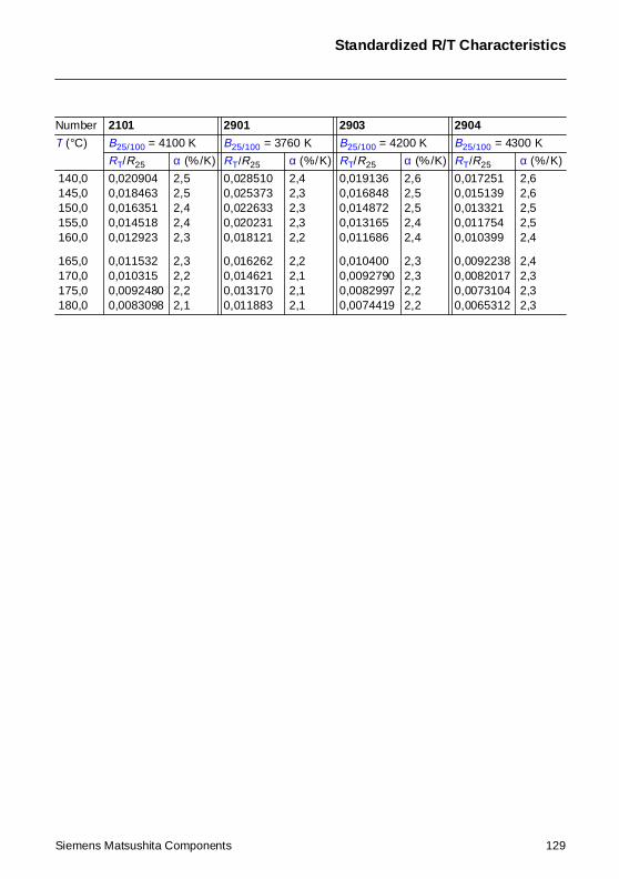
Standardized R/T Characteristics
140,0 145,0 150,0 155,0 160,0
165,0 170,0 175,0 180,0
0,0209040,0184630,0163510,0145180,012923
0,0115320,0103150,00924800,0083098
2,52,52,42,42,3
2,32,22,22,1
0,0285100,0253730,0226330,0202310,018121
0,0162620,0146210,0131700,011883
2,42,32,32,32,2
2,22,12,12,1
0,0191360,0168480,0148720,0131650,011686
0,0104000,00927900,00829970,0074419
2,62,52,52,42,4
2,32,32,22,2
0,0172510,0151390,0133210,0117540,010399
0,00922380,00820170,00731040,0065312
2,62,62,52,52,4
2,42,32,32,3
Number 2101 2901 2903 2904
T (°C) B25/100 = 4100 K B25/100 = 3760 K B25/100 = 4200 K B25/100 = 4300 K
RT/R25 α (%/K) RT/R25 α (%/K) RT/R25 α (%/K) RT/R25 α (%/K)
Siemens Matsushita Components 129
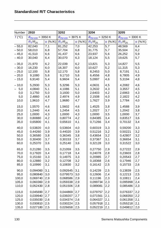
Standardized R/T Characteristics
Number 2910 3202 3204 3205
T (°C) B25/100 = 3950 K B25/100 = 3975 K B25/100 = 3250 K B25/100 = 3300 K
RT/R25 α (%/K) RT/R25 α (%/K) RT/R25 α (%/K) RT/R25 α (%/K)
– 55,0– 50,0– 45,0– 40,0
– 35,0– 30,0– 25,0– 20,0– 15,0
– 10,0– 5,0– 0,0– 5,0– 10,0
– 15,0– 20,0– 25,0– 30,0– 35,0
– 40,0– 45,0– 50,0– 55,0– 60,0
– 65,0– 70,0– 75,0– 80,0– 85,0
– 90,0– 95,0 100,0 105,0 110,0
115,0 120,0 125,0 130,0 135,0
82,04058,01041,51030,040
21,97016,23012,100
9,10806,9140
5,29304,08403,17502,48601,9610
1,55701,24401,00000,808800,65800
0,538200,442600,365800,304000,25370
0,212800,179200,151600,128800,10990
0,0940600,0808400,0697400,0603600,052430
0,0456900,0399400,0350300,0308100,027180
7,16,86,66,4
6,26,05,85,65,4
5,35,15,04,84,7
4,64,44,34,24,1
4,03,93,83,73,6
3,53,43,33,23,1
3,13,02,92,92,8
2,72,72,62,52,5
81,25257,70441,43730,070
22,03916,30712,170
9,17106,9604
5,32964,10863,19302,49741,9680
1,56021,24541,00000,807740,65610
0,536040,440200,363450,301530,25140
0,210590,177180,149750,127080,10830
0,0926450,0795730,0685860,0593380,051506
0,0448690,0392070,0343740,0302240,026658
7,06,86,66,3
6,26,05,85,65,4
5,35,15,04,94,7
4,64,54,34,24,1
4,03,93,83,73,6
3,53,43,33,23,2
3,13,02,92,92,8
2,72,72,62,52,5
42,25331,77523,93718,124
13,82110,627
8,24536,45565,0997
4,06313,26322,64032,15081,7627
1,45251,20271,00000,843850,71266
0,603190,512160,436540,373670,32128
0,277500,240780,209850,183680,16142
0,142390,126060,111960,0997340,089081
0,0797570,0715610,0643270,0579180,052219
5,75,75,65,5
5,35,25,04,84,6
4,54,34,24,03,9
3,83,73,53,43,4
3,33,23,23,13,0
2,92,82,72,62,5
2,52,42,32,32,2
2,22,12,12,12,1
48,56935,50426,25219,625
14,82711,315
8,71916,78055,3194
4,20823,35572,69632,18221,7784
1,45881,20421,00000,835170,70132
0,592000,502210,428070,366540,31522
0,272220,236030,205430,179460,15733
0,138390,122130,108110,0959980,085486
0,0763370,0683500,0613580,0552180,049812
6,46,25,95,7
5,55,35,14,94,8
4,64,54,34,24,0
3,93,83,73,63,4
3,33,23,23,13,0
2,92,82,72,72,6
2,52,52,42,42,3
2,22,22,12,12,0
130 Siemens Matsushita Components
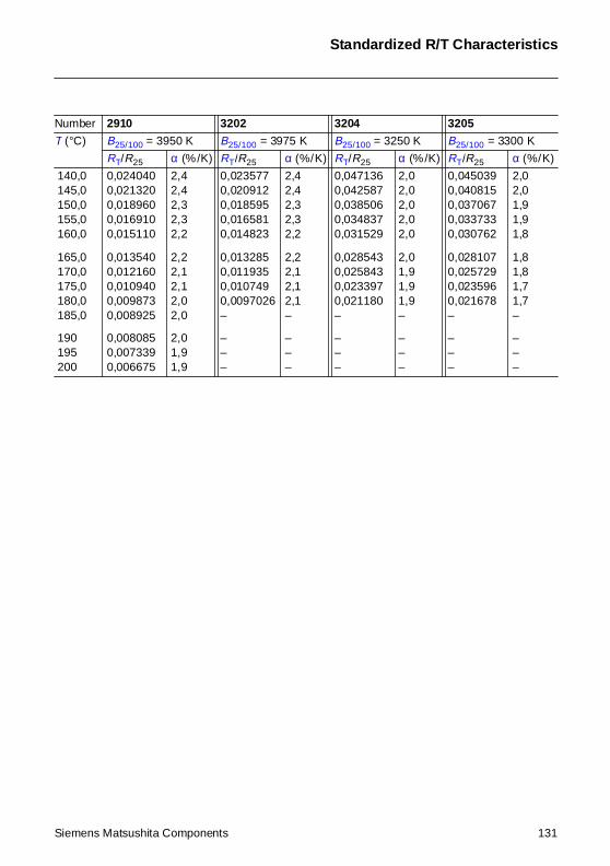
Standardized R/T Characteristics
140,0 145,0 150,0 155,0 160,0
165,0 170,0 175,0 180,0 185,0
190 195 200
0,0240400,0213200,0189600,0169100,015110
0,0135400,0121600,0109400,0098730,008925
0,0080850,0073390,006675
2,42,42,32,32,2
2,22,12,12,02,0
2,01,91,9
0,0235770,0209120,0185950,0165810,014823
0,0132850,0119350,0107490,0097026–
–––
2,42,42,32,32,2
2,22,12,12,1–
–––
0,0471360,0425870,0385060,0348370,031529
0,0285430,0258430,0233970,021180–
–––
2,02,02,02,02,0
2,01,91,91,9–
–––
0,0450390,0408150,0370670,0337330,030762
0,0281070,0257290,0235960,021678–
–––
2,02,01,91,91,8
1,81,81,71,7–
–––
Number 2910 3202 3204 3205
T (°C) B25/100 = 3950 K B25/100 = 3975 K B25/100 = 3250 K B25/100 = 3300 K
RT/R25 α (%/K) RT/R25 α (%/K) RT/R25 α (%/K) RT/R25 α (%/K)
Siemens Matsushita Components 131
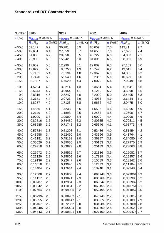
Standardized R/T Characteristics
Number 3206 3207 4001 4002
T (°C) B25/100 = 3450 K B25/100 = 3100 K B25/100 = 3950 K B25/100 = 4250 K
RT/R25 α (%/K) RT/R25 α (%/K) RT/R25 α (%/K) RT/R25 α (%/K)
– 55,0– 50,0– 45,0– 40,0
– 35,0– 30,0– 25,0– 20,0– 15,0
– 10,0– 5,0– 0,0– 5,0– 10,0
– 15,0– 20,0– 25,0– 30,0– 35,0
– 40,0– 45,0– 50,0– 55,0– 60,0
– 65,0– 70,0– 75,0– 80,0– 85,0
– 90,0– 95,0 100,0 105,0 110,0
115,0 120,0 125,0 130,0 135,0
59,14742,65131,08822,903
17,05212,827
9,74617,74705,7897
4,52343,56432,83162,26711,8287
1,48551,21491,00000,828160,68985
0,577840,486580,411810,350200,29918
0,256720,221200,191360,166180,14484
0,126680,111170,0978700,0864280,076549
0,0679920,0605550,0540730,0484070,043439
6,76,46,26,0
5,85,65,45,25,0
4,94,74,54,44,2
4,14,03,83,73,6
3,53,43,33,23,1
3,02,92,92,82,7
2,72,62,52,52,4
2,32,32,22,22,1
36,78127,55920,85815,942
12,2999,57537,51945,95404,7520
3,82143,09542,52472,07281,7125
1,42331,18981,00000,844890,71742
0,612080,524600,451580,390360,33879
0,295150,258090,226470,199400,17614
0,156080,138710,123640,110510,099035
0,0889820,0801470,0723620,0654840,059391
5,95,75,55,3
5,14,94,84,64,4
4,34,14,03,93,8
3,63,53,43,33,2
3,13,03,02,92,8
2,72,62,62,52,4
2,42,32,32,22,2
2,12,12,02,01,9
88,05261,65043,72731,395
22,80216,74212,367
9,23537,0079
5,36544,12603,20002,49861,9662
1,55961,24571,00000,803550,65346
0,534560,439660,363570,301830,25189
0,211360,178190,150890,128330,10948
0,0937480,0807640,0698420,0604550,052498
0,0457400,0399720,0349840,0307000,027100
7,37,06,86,5
6,36,26,05,65,4
5,45,25,04,94,7
4,64,54,44,24,1
4,03,93,83,73,6
3,53,43,33,23,1
3,02,92,92,92,8
2,72,72,62,52,5
113,4177,69554,00838,056
27,15919,61514,36510,629
7,9249
5,96414,50983,44052,64342,0475
1,60051,26001,00000,795110,63773
0,514540,417640,340800,279700,23063
0,190820,158570,132420,111040,093483
0,0790040,0669800,0569820,0487540,041857
0,0360190,0310900,0270040,0235280,020474
7,77,47,16,9
6,66,46,26,05,8
5,65,55,35,15,0
4,94,74,64,54,4
4,24,14,03,93,8
3,73,63,63,53,4
3,33,23,23,13,0
3,02,92,82,82,7
132 Siemens Matsushita Components
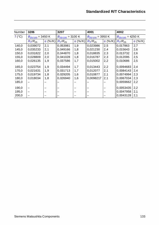
Standardized R/T Characteristics
140,0 145,0 150,0 155,0 160,0
165,0 170,0 175,0 180,0 185,0
190,0 195,0 200,0
0,0390720,0352330,0318220,0288090,026135
0,0237540,0216310,0197340,018034–
–––
2,12,12,02,01,9
1,91,91,81,8–
–––
0,0539810,0491660,0448700,0410280,037586
0,0344940,0317130,0292050,026940–
–––
1,91,81,81,81,7
1,71,71,61,6–
–––
0,0239860,0212300,0188350,0167870,015002
0,0134430,0120770,0108770,0098217–
–––
2,52,42,32,32,2
2,22,12,12,1–
–––
0,0178630,0156430,0137320,0120950,010686
0,00946830,00841430,00749940,00670340,0059662
0,00534350,00479580,0043128
2,72,62,62,52,5
2,42,42,32,32,2
2,22,12,1
Number 3206 3207 4001 4002
T (°C) B25/100 = 3450 K B25/100 = 3100 K B25/100 = 3950 K B25/100 = 4250 K
RT/R25 α (%/K) RT/R25 α (%/K) RT/R25 α (%/K) RT/R25 α (%/K)
Siemens Matsushita Components 133
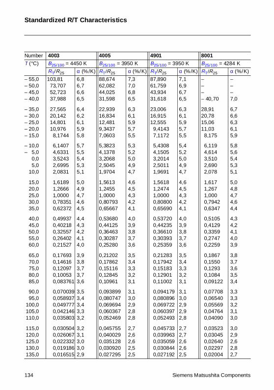
Standardized R/T Characteristics
Number 4003 4005 4901 8001
T (°C) B25/100 = 4450 K B25/100 = 3950 K B25/100 = 3950 K B25/100 = 4284 K
RT/R25 α (%/K) RT/R25 α (%/K) RT/R25 α (%/K) RT/R25 α (%/K)
– 55,0– 50,0– 45,0– 40,0
– 35,0– 30,0– 25,0– 20,0– 15,0
– 10,0– 5,0– 0,0– 5,0– 10,0
– 15,0– 20,0– 25,0– 30,0– 35,0
– 40,0– 45,0– 50,0– 55,0– 60,0
– 65,0– 70,0– 75,0– 80,0– 85,0
– 90,0– 95,0 100,0 105,0 110,0
115,0 120,0 125,0 130,0 135,0
103,8173,70752,72337,988
27,56520,14214,80110,976
8,1744
6,14074,63313,52432,69952,0831
1,61891,26661,00000,783510,62372
0,499370,402180,325570,264020,21527
0,176930,146160,120970,100530,083761
0,0700390,0589370,0497770,0421460,035803
0,0305040,0260670,0223320,0191860,016515
6,86,76,66,5
6,46,26,15,95,8
5,75,55,45,35,1
5,04,94,74,64,5
4,44,34,24,14,0
3,93,83,73,73,6
3,53,43,43,33,2
3,23,13,03,02,9
88,67462,08244,02531,598
22,93916,83412,4819,34377,0603
5,38234,13783,20682,50451,9704
1,56131,24551,00000,807930,65667
0,536800,441250,364630,302870,25280
0,212020,178620,151160,128450,10961
0,0938990,0807470,0696940,0603670,052469
0,0457550,0400290,0351280,0309200,027295
7,37,06,86,5
6,36,15,95,75,5
5,35,25,04,94,7
4,64,54,34,24,1
4,03,93,83,73,6
3,53,43,33,23,1
3,13,02,92,82,8
2,72,62,62,52,5
87,89061,75943,93431,618
23,00616,91512,555
9,41437,1172
5,43084,15053,20142,50111,9691
1,56181,24741,00000,808000,65690
0,537200,442350,366100,303930,25359
0,212830,179420,151830,129010,11002
0,0941790,0808960,0697220,0603970,052493
0,0457330,0399630,0350590,0308440,027192
7,16,96,76,5
6,36,15,95,75,5
5,45,25,04,94,7
4,64,54,34,24,1
4,03,93,83,73,6
3,53,43,33,23,1
3,13,02,92,92,8
2,72,72,62,62,5
–––– 40,70
28,9120,7815,0611,03
8,175
6,1194,6143,5102,6902,078
1,6171,2671,0000,79420,6347
0,51050,41290,33590,27470,2259
0,18670,15500,12930,10840,09122
0,077080,065400,055690,047640,04090
0,035230,030450,026400,022970,02004
–––7,0
6,76,66,36,15,9
5,85,65,45,35,1
5,04,84,74,64,4
4,34,24,14,03,9
3,83,73,63,53,4
3,33,33,23,13,0
3,02,92,62,82,7
134 Siemens Matsushita Components
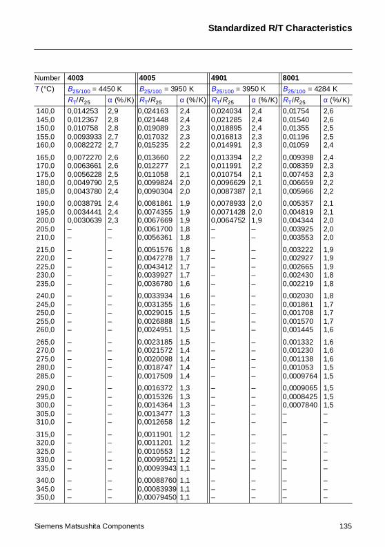
Standardized R/T Characteristics
140,0 145,0 150,0 155,0 160,0
165,0 170,0 175,0 180,0 185,0
190,0 195,0 200,0 205,0 210,0
215,0 220,0 225,0 230,0 235,0
240,0 245,0 250,0 255,0 260,0
265,0 270,0 275,0 280,0 285,0
290,0 295,0 300,0 305,0 310,0
315,0 320,0 325,0 330,0 335,0
340,0 345,0 350,0
0,0142530,0123670,0107580,00939330,0082272
0,00722700,00636610,00562280,00497900,0043780
0,00387910,00344410,0030639––
–––––
–––––
–––––
–––––
–––––
–––
2,92,82,82,72,7
2,62,62,52,52,4
2,42,42,3––
–––––
–––––
–––––
–––––
–––––
–––
0,0241630,0214480,0190890,0170320,015235
0,0136600,0122770,0110580,00998240,0090304
0,00818610,00743550,00676690,00617000,0056361
0,00515760,00472780,00434120,00399270,0036780
0,00339340,00313550,00290150,00268880,0024951
0,00231850,00215720,00200980,00187470,0017509
0,00163720,00153260,00143640,00134770,0012658
0,00119010,00112010,00105530,000995210,00093943
0,000887600,000839390,00079450
2,42,42,32,32,2
2,22,12,12,02,0
1,91,91,91,81,8
1,81,71,71,71,6
1,61,61,51,51,5
1,51,41,41,41,4
1,31,31,31,31,2
1,21,21,21,21,1
1,11,11,1
0,0240340,0212850,0188950,0168130,014991
0,0133940,0119910,0107540,00966290,0087387
0,00789330,00714280,0064752––
–––––
–––––
–––––
–––––
–––––
–––
2,42,42,42,32,3
2,22,22,12,12,1
2,02,01,9––
–––––
–––––
–––––
–––––
–––––
–––
0,017540,015400,013550,011960,01059
0,0093980,0083590,0074530,0066590,005966
0,0053570,0048190,0043440,0039250,003553
0,0032220,0029270,0026650,0024300,002219
0,0020300,0018610,0017080,0015700,001445
0,0013320,0012300,0011380,0010530,0009764
0,00090650,00084250,0007840––
–––––
–––
2,62,62,52,52,4
2,42,32,32,22,2
2,12,12,02,02,0
1,91,91,91,81,8
1,81,71,71,71,6
1,61,61,61,51,5
1,51,51,5––
–––––
–––
Number 4003 4005 4901 8001
T (°C) B25/100 = 4450 K B25/100 = 3950 K B25/100 = 3950 K B25/100 = 4284 K
RT/R25 α (%/K) RT/R25 α (%/K) RT/R25 α (%/K) RT/R25 α (%/K)
Siemens Matsushita Components 135
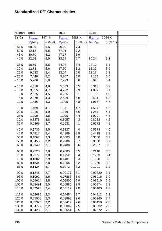
Standardized R/T Characteristics
Number 8010 8016 8018
T (°C) B25/100 = 3474 K B25/100 = 3988 K B25/100 = 3964 K
RT/R25 α (%/K) RT/R25 α (%/K) RT/R25 α (%/K)
– 55,0– 50,0– 45,0– 40,0
– 35,0– 30,0– 25,0– 20,0– 15,0
– 10,0– 5,0– 0,0– 5,0– 10,0
– 15,0– 20,0– 25,0– 30,0– 35,0
– 40,0– 45,0– 50,0– 55,0– 60,0
– 65,0– 70,0– 75,0– 80,0– 85,0
– 90,0– 95,0 100,0 105,0 110,0
115,0 120,0 125,0 130,0 135,0
58,2542,1230,7022,66
16,8912,73
9,6837,4405,766
4,5103,5552,8252,2701,836
1,4891,2161,0000,82760,6869
0,57360,48170,40670,34550,2949
0,25280,21770,18820,16340,1424
0,12450,10920,096140,084910,07523
0,066850,059580,053250,047720,04288
6,66,56,26,0
5,85,65,45,25,0
4,84,74,54,34,3
4,14,03,83,83,7
3,53,43,33,23,1
3,03,02,92,82,7
2,72,62,52,52,4
2,32,32,22,22,1
96,3067,0147,1733,65
24,2617,7013,04
9,7077,293
5,5334,2323,2652,5391,990
1,5711,2491,0000,80570,6531
0,53270,43690,36030,29860,2488
0,20830,17520,14810,12580,1072
0,091770,078850,068000,058860,05112
0,044540,038930,034170,030090,02654
7,47,26,96,7
6,46,26,05,85,6
5,55,35,15,04,8
4,74,54,44,34,1
4,03,93,83,73,6
3,53,43,33,23,2
3,13,02,92,92,8
2,72,62,62,52,5
–––30,24
22,1016,3212,17
9,1536,945
5,3134,0973,1832,4911,963
1,5571,2441,0000,80830,6572
0,53730,44180,36500,30300,2527
0,21180,17830,15080,12800,1091
0,093300,080160,069100,059740,05183
0,045120,039400,034500,030320,02672
–––6,3
6,15,95,85,65,4
5,25,14,94,84,7
4,64,44,34,24,1
4,03,93,73,73,6
3,53,43,33,23,2
3,13,02,92,92,8
2,82,72,62,62,5
136 Siemens Matsushita Components
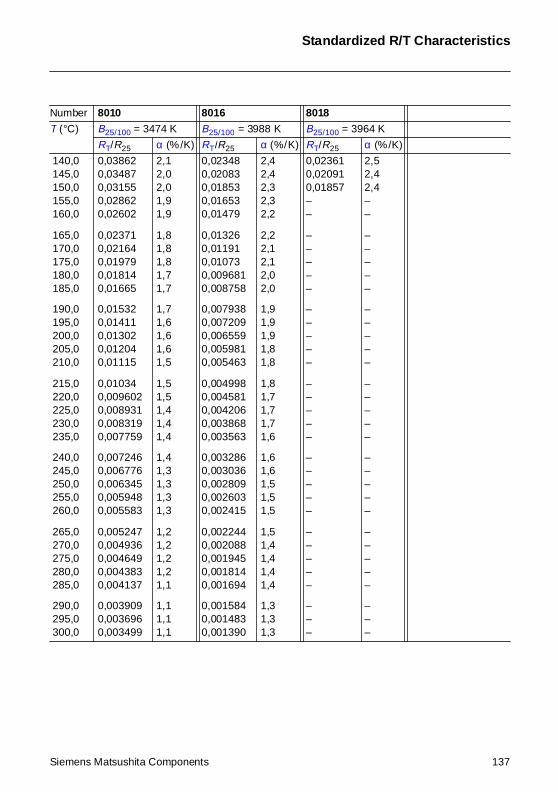
Standardized R/T Characteristics
140,0 145,0 150,0 155,0 160,0
165,0 170,0 175,0 180,0 185,0
190,0 195,0 200,0 205,0 210,0
215,0 220,0 225,0 230,0 235,0
240,0 245,0 250,0 255,0 260,0
265,0 270,0 275,0 280,0 285,0
290,0 295,0 300,0
0,038620,034870,031550,028620,02602
0,023710,021640,019790,018140,01665
0,015320,014110,013020,012040,01115
0,010340,0096020,0089310,0083190,007759
0,0072460,0067760,0063450,0059480,005583
0,0052470,0049360,0046490,0043830,004137
0,0039090,0036960,003499
2,12,02,01,91,9
1,81,81,81,71,7
1,71,61,61,61,5
1,51,51,41,41,4
1,41,31,31,31,3
1,21,21,21,21,1
1,11,11,1
0,023480,020830,018530,016530,01479
0,013260,011910,010730,0096810,008758
0,0079380,0072090,0065590,0059810,005463
0,0049980,0045810,0042060,0038680,003563
0,0032860,0030360,0028090,0026030,002415
0,0022440,0020880,0019450,0018140,001694
0,0015840,0014830,001390
2,42,42,32,32,2
2,22,12,12,02,0
1,91,91,91,81,8
1,81,71,71,71,6
1,61,61,51,51,5
1,51,41,41,41,4
1,31,31,3
0,023610,020910,01857––
–––––
–––––
–––––
–––––
–––––
–––
2,52,42,4––
–––––
–––––
–––––
–––––
–––––
–––
Number 8010 8016 8018
T (°C) B25/100 = 3474 K B25/100 = 3988 K B25/100 = 3964 K
RT/R25 α (%/K) RT/R25 α (%/K) RT/R25 α (%/K)
Siemens Matsushita Components 137
SCS – dependable, fast and competent
Ceramic chip capacitors from stock
Siemens Matsushita ComponentsCOMPONENTS
+S M
Small in size, big in performance
Our selection of capacitors rangesfrom standard sizes down to a mini-ature highlight in 0402 style. Mea-suring only 1 x 0.5 x 0.5 mm, it’s anideal solution for applications wherespace is tight, like in handies andcardiac pacemakers. At the sametime all our chips can boast excellentsoldering characteristics, with specialterminal variants for conductive ad-hesion. And we also thought aboutthe right packing for automatic place-ment. You get all sizes down to 1206in bulk case for example, plus voltageratings from 16 to 500 V. By the way,our leaded models have CECCapproval of course, in fact theywere certified more than tenyears ago.
More in the new short form catalog!
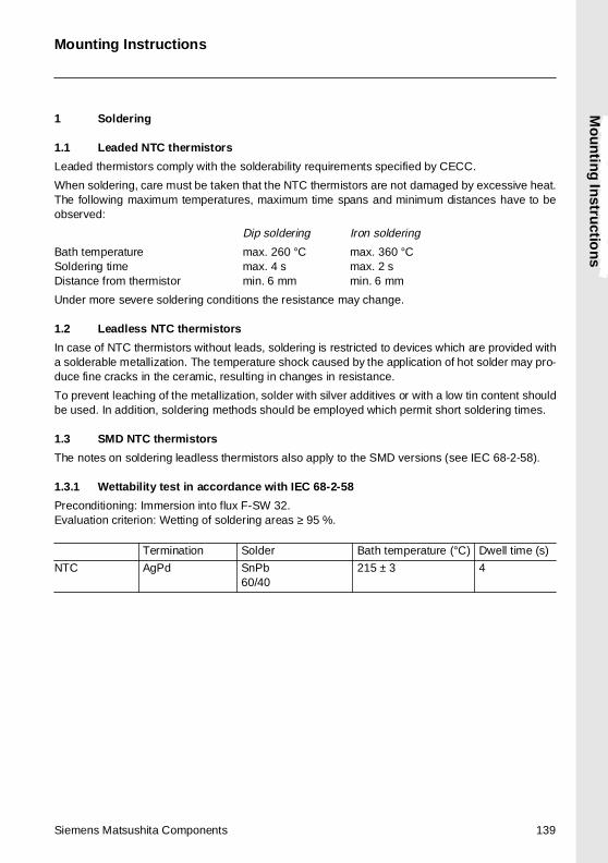
Mo
un
ting
Instru
ction
s
Mounting Instructions
1 Soldering
1.1 Leaded NTC thermistors
Leaded thermistors comply with the solderability requirements specified by CECC.
When soldering, care must be taken that the NTC thermistors are not damaged by excessive heat.The following maximum temperatures, maximum time spans and minimum distances have to beobserved:
Dip soldering Iron soldering
Bath temperature max. 260 °C max. 360 °CSoldering time max. 4 s max. 2 sDistance from thermistor min. 6 mm min. 6 mm
Under more severe soldering conditions the resistance may change.
1.2 Leadless NTC thermistors
In case of NTC thermistors without leads, soldering is restricted to devices which are provided witha solderable metallization. The temperature shock caused by the application of hot solder may pro-duce fine cracks in the ceramic, resulting in changes in resistance.
To prevent leaching of the metallization, solder with silver additives or with a low tin content shouldbe used. In addition, soldering methods should be employed which permit short soldering times.
1.3 SMD NTC thermistors
The notes on soldering leadless thermistors also apply to the SMD versions (see IEC 68-2-58).
1.3.1 Wettability test in accordance with IEC 68-2-58
Preconditioning: Immersion into flux F-SW 32.Evaluation criterion: Wetting of soldering areas ≥ 95 %.
Termination Solder Bath temperature (°C) Dwell time (s)
NTC AgPd SnPb60/40
215 ± 3 4
Siemens Matsushita Components 139
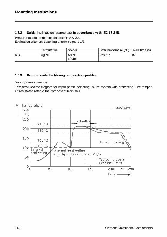
Mounting Instructions
1.3.2 Soldering heat resistance test in accordance with IEC 68-2-58
Preconditioning: Immersion into flux F-SW 32.Evaluation criterion: Leaching of side edges ≤ 1/3.
1.3.3 Recommended soldering temperature profiles
Vapor phase soldering
Temperature/time diagram for vapor phase soldering, in-line system with preheating. The temper-atures stated refer to the component terminals.
Termination Solder Bath temperature (°C) Dwell time (s)
NTC AgPd SnPb60/40
260 ± 5 10
140 Siemens Matsushita Components
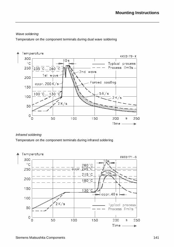
Mounting Instructions
Wave soldering
Temperature on the component terminals during dual wave soldering
Infrared soldering
Temperature on the component terminals during infrared soldering
Siemens Matsushita Components 141
Mounting Instructions
1.3.4 Notes
Iron soldering should be avoided, hot air methods are recommended for repair purposes.
2 Conductive adhesion
An alternative to soldering is the gluing of thermistors with conductive adhesives. The benefit of thismethod is that it involves no thermal stress. The adhesives used must be chemically inert.
3 Clamp contacting
Pressure contacting by means of clamps is particularly suitable for applications involving frequentswitching and high turn-on powers.
4 Robustness of terminations
The leads meet the requirements of IEC 68-2-21. They may not be bent closer than 4 mm from thesolder joint on the thermistor body or from the point at which they leave the feed-throughs. Duringbending, any mechanical stress at the outlet of the leads must be removed. The bending radiusshould be at least 0,75 mm.
Tensile strength: Test Ua1:Leads ∅ ≤ 0,5 mm = 5 N
∅ > 0,5 mm = 10 N
Bending strength: Test Ub:Two 90°-bends in opposite directions at a weight of 0,25 kg.
Torsional strength: Test Uc: severity 2The lead is bent by 90° at a distance of 6 to 6,5 mm from the thermistor body.The bending radius of the leads should be approx. 0,75 mm. Two torsions of180° each (severity 2).
When subjecting leads to mechanical stress, the following should be observed:
Tensile stress on leads
During mounting and operation tensile forces on the leads are to be avoided.
Bending of leads
Bending of the leads directly on the thermistor body is not permissible.
A lead may be bent at a minimum distance of twice the wire’s diameter + 2 mm from the solder jointon the thermistor body. During bending the wire must be mechanically relieved at its outlet. Thebending radius should be at least 0,75 mm.
Twisting of leads
The twisting (torsion) by 180° of a lead bent by 90° is permissible at 6 mm from the bottom of thethermistor body.
142 Siemens Matsushita Components
Mounting Instructions
5 Sealing and potting
When thermistors are sealed or potted, there must be no mechanical stress through differing ther-mal expansion in the curing process and during later operation. In the curing process the upper cat-egory temperature of the thermistor must not be exceeded. It is also necessary to ensure that thepotting compound is chemically neutral.
6 Cleaning
If cleaning is necessary, mild cleaning agents such as freon, trichloroethane and perchloroethyleneare recommended. Ultrasonic cleaning methods are permissible.
7 Storage
In order to maintain their solderability, thermistors must be stored in a non-corrosive atmosphere.Humidity, temperature and container materials are critical factors.
If possible, the components should be left in the original packing. Touching the metallization of un-soldered thermistors may change their soldering properties.
Siemens Matsushita Components 143
Siemens Matsushita ComponentsCOMPONENTS
+S M
Ferrite cores and accessories
In place,in shape
With more than 4000 different ferrite cores we have the solutionto tackle every application. Straightfrom SCS stock we can supply you 12 core shopes in as many as26 materials, plus the matchingaccessories:
þ RM for transformers with high packing density
þ PM for power transformers þ P for transformers with
extremely low leakage field þ E cores
ETD, EC, ER with round center leg for compact transformers,EFD with flattened center leg for ultra flat transformers,wide range of standard E cores
þ U for storage chokes, split diode and line transformers
þ Ring for pulse, broadband and balun transformers plus chokes
þ Double-aperture for broadbandtransformers up into the GHz region
SCS – dependable, fast and competent
SBS-Layout Ferrite+Zu. 01.09.1996 17:24 Uhr Seite 2
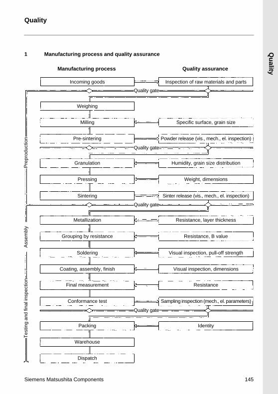
Siemens Matsushita C
1 Manufacturing
Inco
Pr
G
M
Groupin
S
Coating,
Final
Conf
W
Tes
ting
and
final
insp
ectio
nP
repr
oduc
tion
Ass
embl
y
Manufac
Quality
process and quality assurance
Quality gate
ming goods Inspection of raw materials and parts
Milling Specific surface, grain size
Weighing
Quality gate
Quality gate
e-sintering Powder release (vis., mech., el. inspection)
ranulation Humidity, grain size distribution
Pressing Weight, dimensions
Sintering Sinter release (vis., mech., el. inspection)
etallization Resistance, layer thickness
g by resistance Resistance, B value
oldering Visual inspection, pull-off strength
assembly, finish Visual inspection, dimensions
measurement Resistance
turing process Quality assurance
Quality
omponents 145
Quality gate
ormance test Sampling inspection (mech., el. parameters)
Packing Identity
arehouse
Dispatch
Quality
2 General
S+M has set up extensive quality assurance systems in order to meet the stringent technical de-mands of an open world market. These systems follow the CECC ISO-9000 to ISO-9004 standards.Our QA system received the ISO 9001 certificate in September 1991.
3 Sequence of quality assurance measures
The quality department tested and released the thermistors described in this data book on the basisof the following criteria: compliance with type specifications, process capability of production equip-ment as well as accuracy of measuring and test methods and equipment.
To ensure a constantly high quality level, the following tests are carried out:
3.1 Incoming inspection
The parts and materials required for production are checked for dimensional accuracy and materialproperties in a prescribed sequence.
3.2 Process assurance
To achieve the objective of eliminating defects as efficiently as possible and at their very source,quite different measures are taken. Modern quality tools such as FMEA (Failure Mode and EffectAnalysis) are used already during the starting phase: A risk-priority figure is assigned to potentialdefects according to their significance as well as to the probability of occurrence and detection. Incase of high risk-priority figures, remedial measures are taken from the beginning. During produc-tion all essential processes are subject to statistical process control (SPC).
3.3 Product assurance
Each manufacturing stage is followed by a socalled “quality control gate”, i.e. the product is onlyreleased for the next stage after passing a corresponding test. The test results are constantly mon-itored and evaluated and are then used to assess the quality of the manufacturing process itself(refer to 3.2).
3.4 Final inspection
Final measurements and conformance tests ensure that delivery quality is kept constant within de-fined tolerances.
4 Delivery quality
The term delivery quality designates the conformance with agreed data at the time of delivery.
146 Siemens Matsushita Components
Quality
5 Sampling inspection
The customer may carry out incoming inspections which are subject to standardized sampling in-spection plans specifying the acceptance or rejection of a delivery lot in conjunction with agreedAQL values (AQL = acceptable quality level).
The scope and the maximum permissible number of defects of a sampling inspection are specifiedin IEC 410 (identical with MIL-STD 105 D and DIN ISO 2859-1), single sampling plan for normalinspection, inspection level II. The sampling instructions of this standard are such that a deliveredlot will be accepted with a high degree of probability (greater than 90 %), if the percentage of defec-tives does not exceed the specified AQL level.
Generally, the average defect percentage of our deliveries lies clearly below the AQL value. This isensured by appropriate quality assurance measures in the manufacturing plants and substantiatedby the final inspections.
6 Classification of defects
A component is considered defective if it does not comply with the specifications stated in the datasheets or in an agreed delivery specification. Defects which generally exclude the functional use ofthe component (inoperatives) are classified separately from less significant defects.
Inoperatives of thermistors are:
– Short circuit or open circuit– Component, case, terminals or encapsulation broken– Incorrect marking– Mixing of different types
Other defects are:
– Electrical defects (maximum ratings are exceeded)– Mechanical defects, e. g. incorrect dimensions, damaged housings, illegible marking, twisted
leads
7 AQL values
The following AQL values apply to the quoted defects
– for inoperatives (electrical and mechanical) 0,065– for the total number of electrical defectives 0,250– for the total number of mechanical defectives 0,250
The values for the total number of defectives include related inoperatives.
Siemens Matsushita Components 147
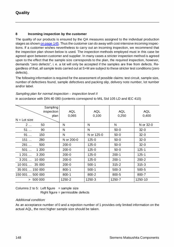
Quality
8 Incoming inspection by the customer
The quality of our products is ensured by the QA measures assigned to the individual productionstages as shown on page 145. Thus the customer can do away with cost-intensive incoming inspec-tions. If a customer wishes nevertheless to carry out an incoming inspection, we recommend thatthe inspection plan shown below is used. The inspection methods employed must in this case beagreed upon between customer and supplier. In many cases a stricter inspection method is agreedupon to the effect that the sample size corresponds to the plan, the required inspection, however,demands “zero defects”, i. e. a lot will only be accepted if the samples are free from defects. Re-gardless of that, all sample tests carried out at S+M are subject to these stricter test conditions (zerodefects).
The following information is required for the assessment of possible claims: test circuit, sample size,number of defectives found, sample defectives and packing slip, delivery note number, lot numberand/or label.
Sampling plan for normal inspection – inspection level II
in accordance with DIN 40 080 (contents correspond to MIL Std 105 LD and IEC 410)
Columns 2 to 5: Left figure = sample sizeRight figure = permissible defects
Additional condition:
As an acceptance number of 0 and a rejection number of 1 provides only limited information on theactual AQL, the next higher sample size should be taken.
Samplinginspection
planN = Lot size
AQL0,065
AQL0,100
AQL0,250
AQL0,400
2 … 50 N N N N or 32-0
51 … 90 N N 50-0 32-0
91 … 150 N N or 125-0 50-0 32-0
151 … 280 N or 200-0 125-0 50-0 32-0
281 … 500 200-0 125-0 50-0 32-0
501 … 1 200 200-0 125-0 50-0 125-1
1 201 … 3 200 200-0 125-0 200-1 125-1
3 201 … 10 000 200-0 125-0 200-1 200-2
10 001 … 35 000 200-0 500-1 315-2 315-3
35 001 … 150 000 800-1 500-1 500-3 500-5
150 001 … 500 000 800-1 800-2 800-5 800-7
> 500 000 1250-2 1250-3 1250-7 1250-10
148 Siemens Matsushita Components
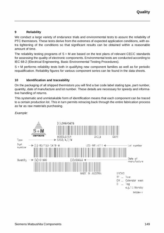
Quality
9 Reliability
We conduct a large variety of endurance trials and environmental tests to assure the reliability ofPTC thermistors. These tests derive from the extremes of expected application conditions, with ex-tra tightening of the conditions so that significant results can be obtained within a reasonableamount of time.
The reliability testing programs of S + M are based on the test plans of relevant CECC standardsfor assessing the quality of electronic components. Environmental tests are conducted according toIEC 68-2 (Electrical Engineering, Basic Environmental Testing Procedures).
S + M performs reliability tests both in qualifying new component families as well as for periodicrequalification. Reliability figures for various component series can be found in the data sheets.
10 Identification and traceability
On the packaging of all shipped thermistors you will find a bar code label stating type, part number,quantity, date of manufacture and lot number. These details are necessary for speedy and informa-tive handling of returns.
This systematic and unmistakable form of identification means that each component can be tracedto a certain production lot. This in turn permits retracing back through the entire fabrication processas far as raw materials purchasing.
Example:
Siemens Matsushita Components 149
Quality
11 Supplementary information
The issuing of quality data – which always relate to a large number of components – is no assuranceof characteristics in a legal sense. But an agreement on such data does not exclude the customer’sright to claim replacement of individual defective NTC thermistors within the terms of delivery. Wecannot assume any further liability, especially for the consequences of component failure.
You should also remember that figures for failure rate refer to an average fabrication situation andare therefore to be understood as mean values (statistical expectations) for a large number of de-livery lots of homogeneous NTC thermistors. They are based on application experience as well ason data derived from preceding inspection under normal or – for the purpose of acceleration – tight-ened conditions.
150 Siemens Matsushita Components
Siemens Matsushita Components 151
Siemens Matsushita Components GmbH & Co. KG (S + M Components for short) is responsible forprotection of the environment in the development, fabrication and use of its products for the intend-ed purpose. S + M Components is very thorough in fulfilling the resulting obligations. Over andabove the legal prescriptions, our guiding principle here is the corporation’s responsibility towardsman and environment.
Responsibility for safety in working with materials that have a potential environmental impact is inthe hands of the various managers. This involves, in the first place, instructing and informing thestaff concerned. A specially trained environmental protection supervisor watches over adherenceto regulations, reports on the introduction of processes within an environmental context and on de-cisions relating to investment (e.g. he checks that all environmentally associated requirements likefilters and sumps have been considered). But advising and informing staff take on the highest pri-ority; this is the only way to ensure that all protective measures are known and observed.
All chemicals employed in development and fabrication are examined for environmental compati-bility or harmful effects before their use on the basis of DIN safety specifications. Alternatives aredevised if risks emerge. The result of this procedure is that today all CFCs as well as all highly toxicmaterials have been eliminated entirely from the fabrication process.
Dust and vapor generated during fabrication are filtered away for disposal. The emission figures ofthe filters are constantly examined; considerable efforts are undertaken to ensure that these figuresare well below the legally prescribed limits. The same applies to the water used in a plant. This beingcleansed in a special waste-water treatment process. Water consumption has been reduced sub-stantially in recent years through the use of cooling water circuits and water recycling.
Waste produced in the fabrication of components is sorted and collected on the spot and recycledby state-of-the-art methods.
The packaging material used for our components can be fully recycled.
All NTC thermistors can be disposed of on a dump for industrial waste that is similar to householdrefuse without any special precautions.
Of course, we are still by no means satisfied with what we have already achieved, and more stepsare due to follow in the interest of further reducing and ultimately eliminating entirely all environmen-tal impact created in the development and fabrication of our components.
En
viron
men
tal Pro
tectio
n M
easu
res
Environmental Protection Measures
New lab assortments in filmcapacitors
SCS – dependable, fast and competent
Five at a stroke
To save you the trouble of inquiringfor individual ratings to put into yourdesign, there are now five practicalsets of film capacitors:
þ Lead spacing 5: 525 types, 50 to 400 V, 1 nF to 3.3 µF
þ SilverCaps: the lowest-cost models, low in volume, 63 to 400 V, 1 nF to 10 µF
þ MKPs in wound technology: forRF applications, 250 to 2000 V, 1.5 nF to 0.68 µF
þ MKPs in stacked-film tech-nology: 300 types, 160 to 1000 V, 1.5 nF to 1 µF
þ Interference suppression: 150 types with a wide choice of ratings for different applications – X2 with small dimensions, Safe-X for maximum security against active flammability (X2) and Y for suppressing common-mode interference (Y2)
Siemens Matsushita ComponentsCOMPONENTS
+S M
SBS-15.4 01.09.1996 17:58 Uhr Seite 2
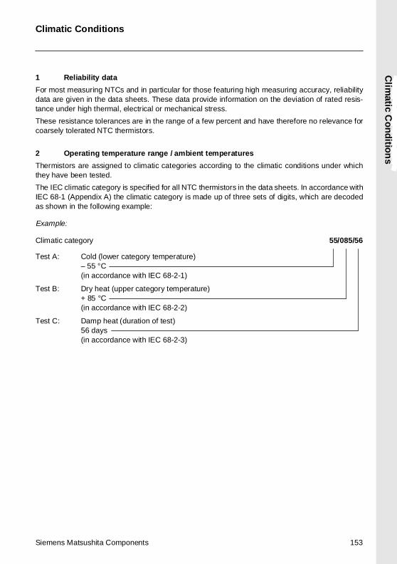
Siemens Matsushita Components 153
1 Reliability data
For most measuring NTCs and in particular for those featuring high measuring accuracy, reliabilitydata are given in the data sheets. These data provide information on the deviation of rated resis-tance under high thermal, electrical or mechanical stress.
These resistance tolerances are in the range of a few percent and have therefore no relevance forcoarsely tolerated NTC thermistors.
2 Operating temperature range / ambient temperatures
Thermistors are assigned to climatic categories according to the climatic conditions under whichthey have been tested.
The IEC climatic category is specified for all NTC thermistors in the data sheets. In accordance withIEC 68-1 (Appendix A) the climatic category is made up of three sets of digits, which are decodedas shown in the following example:
Example:
Climatic category 55/085/56
Test C: Damp heat (duration of test)56 days(in accordance with IEC 68-2-3)
Test B: Dry heat (upper category temperature)+ 85 °C(in accordance with IEC 68-2-2)
Test A: Cold (lower category temperature)– 55 °C(in accordance with IEC 68-2-1)
Clim
atic Co
nd
ition
s
Climatic Conditions

SCS – dependable, fast and competent
A whole lot of ring core chokes
Siemens Matsushita ComponentsCOMPONENTS
+S M
Chokes to your choice
You urgently need particular ringcore chokes? That’s no problem, wehave 200,000 pieces in stock anddeliver reliably through SCS. Ourautomated production guarantees
the best of reliability too. It turns outchokes in different versions: flat andupright, with current rated from 0.4to 16 A. UL and VDE approved, andcomplying with the latest EMC stan-dards of course.
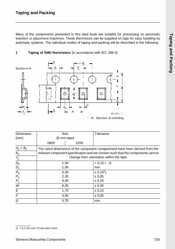
Tap
ing and
Packin
g
Taping and Packing
Many of the components presented in this data book are suitable for processing on automaticinsertion or placement machines. These thermistors can be supplied on tape for easy handling byautomatic systems. The individual modes of taping and packing will be described in the following.
1 Taping of SMD thermistors (in accordance with IEC 286-3)
1) ≤ 0,2 mm over 10 sprocket holes
Dimension(mm)
Size(8 mm tape)
Tolerance
0805 1206
A0 × B0 The rated dimensions of the component compartment have been derived from the relevant component specification and are chosen such that the components cannot
change their orientation within the tape.K0
T2
D0D1
1,501,00
+ 0,10 / – 0min.
P0P2P1
4,002,004,00
± 0,101)± 0,05± 0,10
W 8,00 ± 0,30
E 1,75 ± 0,10
F 3,50 ± 0,05
G 0,75 min.
Direction of unreeling
Section A-A
Siemens Matsushita Components 155
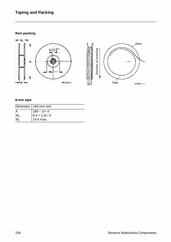
Taping and Packing
Reel packing
8-mm tape
Dimension 180-mm reel
AW1W2
180 – 2/+ 08,4 + 1,5/– 014,4 max.
Dire
ctio
n of
unr
eelin
g
Tape
Reel
156 Siemens Matsushita Components
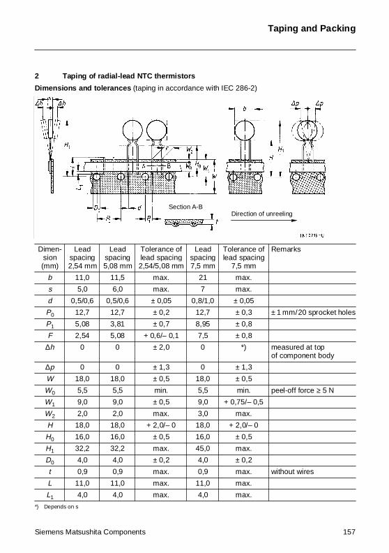
Taping and Packing
2 Taping of radial-lead NTC thermistors
Dimensions and tolerances (taping in accordance with IEC 286-2)
*) Depends on s
Dimen-sion(mm)
Leadspacing2,54 mm
Leadspacing5,08 mm
Tolerance oflead spacing2,54/5,08 mm
Leadspacing7,5 mm
Tolerance oflead spacing
7,5 mm
Remarks
b 11,0 11,5 max. 21 max.
s 5,0 6,0 max. 7 max.
d 0,5/0,6 0,5/0,6 ± 0,05 0,8/1,0 ± 0,05
P0 12,7 12,7 ± 0,2 12,7 ± 0,3 ± 1 mm/20 sprocket holes
P1 5,08 3,81 ± 0,7 8,95 ± 0,8
F 2,54 5,08 + 0,6/– 0,1 7,5 ± 0,8
∆h 0 0 ± 2,0 0 *) measured at topof component body
∆p 0 0 ± 1,3 0 ± 1,3
W 18,0 18,0 ± 0,5 18,0 ± 0,5
W0 5,5 5,5 min. 5,5 min. peel-off force ≥ 5 N
W1 9,0 9,0 ± 0,5 9,0 + 0,75/– 0,5
W2 2,0 2,0 max. 3,0 max.
H 18,0 18,0 + 2,0/– 0 18,0 + 2,0/– 0
H0 16,0 16,0 ± 0,5 16,0 ± 0,5
H1 32,2 32,2 max. 45,0 max.
D0 4,0 4,0 ± 0,2 4,0 ± 0,2
t 0,9 0,9 max. 0,9 max. without wires
L 11,0 11,0 max. 11,0 max.
L1 4,0 4,0 max. 4,0 max.
Section A-BDirection of unreeling
Siemens Matsushita Components 157
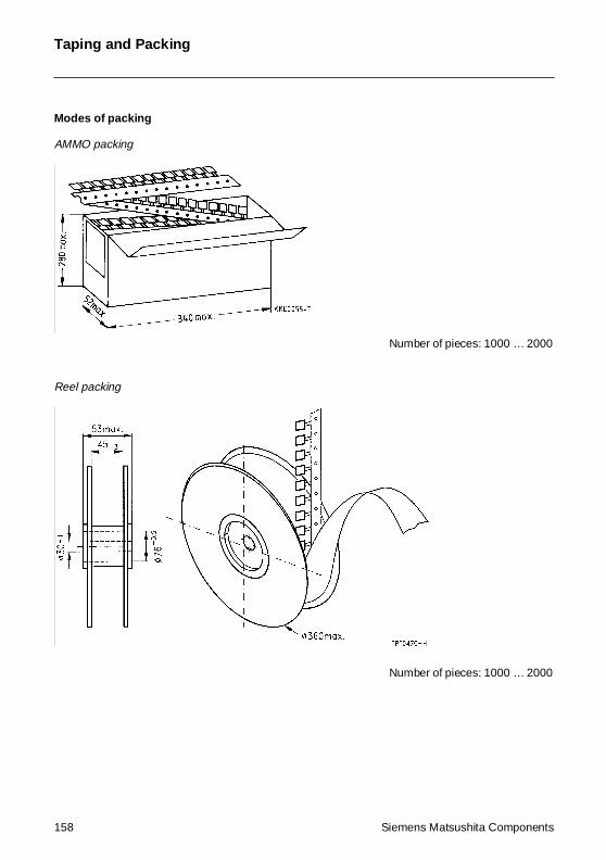
Taping and Packing
Modes of packing
AMMO packing
Reel packing
Number of pieces: 1000 … 2000
Number of pieces: 1000 … 2000
158 Siemens Matsushita Components
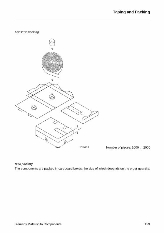
Taping and Packing
Cassette packing
Bulk packing
The components are packed in cardboard boxes, the size of which depends on the order quantity.
Number of pieces: 1000 … 2000
Siemens Matsushita Components 159
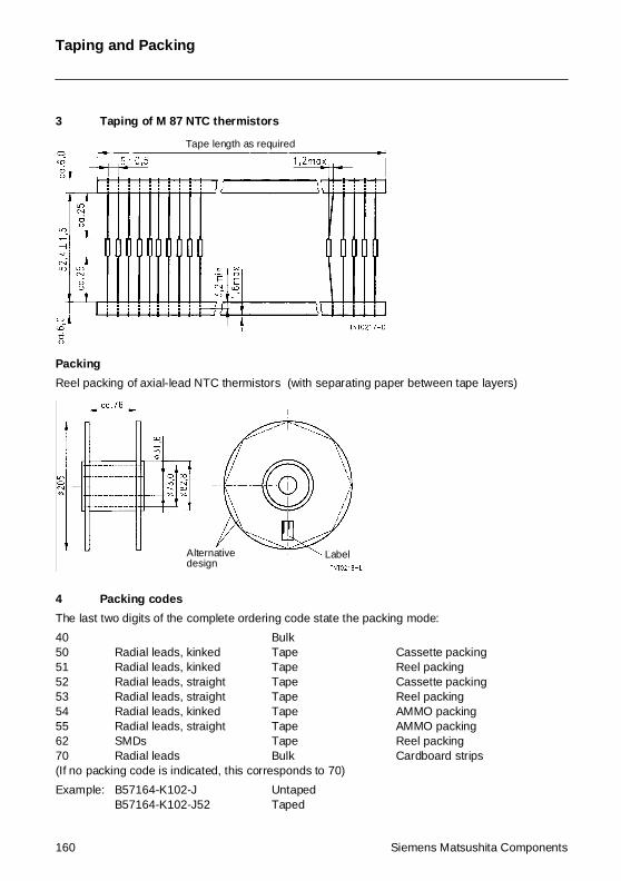
Taping and Packing
3 Taping of M 87 NTC thermistors
Packing
Reel packing of axial-lead NTC thermistors (with separating paper between tape layers)
4 Packing codes
The last two digits of the complete ordering code state the packing mode:
40 Bulk50 Radial leads, kinked Tape Cassette packing51 Radial leads, kinked Tape Reel packing 52 Radial leads, straight Tape Cassette packing53 Radial leads, straight Tape Reel packing54 Radial leads, kinked Tape AMMO packing55 Radial leads, straight Tape AMMO packing62 SMDs Tape Reel packing70 Radial leads Bulk Cardboard strips(If no packing code is indicated, this corresponds to 70)
Example: B57164-K102-J UntapedB57164-K102-J52 Taped
Tape length as required
LabelAlternativedesign
160 Siemens Matsushita Components
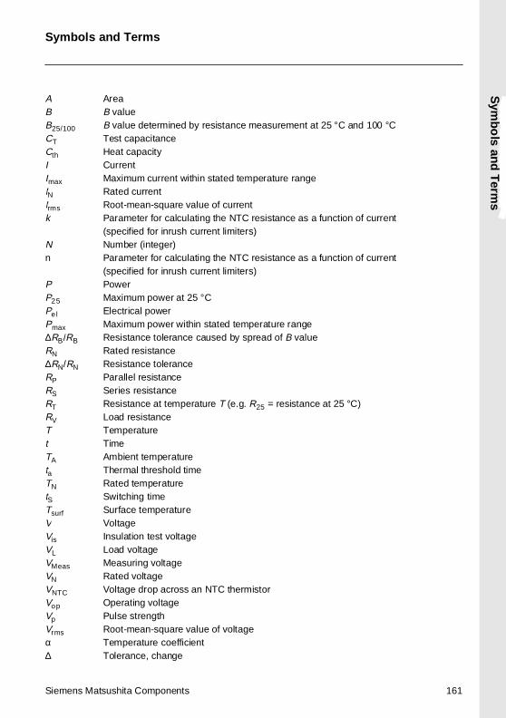
Sym
bo
ls and
Term
s
Symbols and Terms
A AreaB B valueB25/100 B value determined by resistance measurement at 25 °C and 100 °CCT Test capacitanceCth Heat capacityI CurrentImax Maximum current within stated temperature rangeIN Rated currentIrms Root-mean-square value of currentk Parameter for calculating the NTC resistance as a function of current
(specified for inrush current limiters)N Number (integer)n Parameter for calculating the NTC resistance as a function of current
(specified for inrush current limiters)P PowerP25 Maximum power at 25 °CPel Electrical powerPmax Maximum power within stated temperature range∆RB/RB Resistance tolerance caused by spread of B valueRN Rated resistance∆RN/RN Resistance toleranceRP Parallel resistanceRS Series resistanceRT Resistance at temperature T (e.g. R25 = resistance at 25 °C)RV Load resistanceT Temperaturet TimeTA Ambient temperatureta Thermal threshold timeTN Rated temperaturetS Switching timeTsurf Surface temperatureV VoltageVis Insulation test voltageVL Load voltageVMeas Measuring voltageVN Rated voltageVNTC Voltage drop across an NTC thermistorVop Operating voltageVp Pulse strengthVrms Root-mean-square value of voltageα Temperature coefficient∆ Tolerance, change
Siemens Matsushita Components 161
Symbols and Terms
δ th Dissipation factorτa Thermal time constantτc Thermal cooling time constantλ Failure rate
Abbreviations / Notes
Surface-mount devices
* To be replaced by a number in ordering codes, type designations etc.
+ To be replaced by a letter
All dimensions are given in mm.
The commas used in numerical values denote decimal points.
162 Siemens Matsushita Components
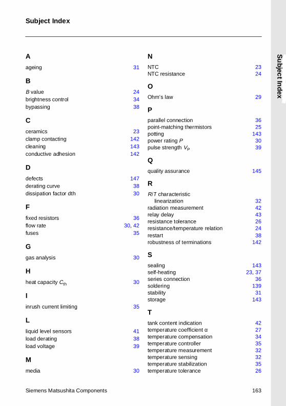
Subject Index
Su
bjec
t Ind
ex
A
ageing 31
B
B value 24brightness control 34bypassing 38
C
ceramics 23clamp contacting 142cleaning 143conductive adhesion 142
D
defects 147derating curve 38dissipation factor dth 30
F
fixed resistors 36flow rate 30, 42fuses 35
G
gas analysis 30
H
heat capacity Cth 30
I
inrush current limiting 35
L
liquid level sensors 41load derating 38load voltage 39
M
media 30
N
NTC 23NTC resistance 24
O
Ohm’s law 29
Pparallel connection 36point-matching thermistors 25potting 143power rating P 30pulse strength VP 39
Q
quality assurance 145
R
R/T characteristiclinearization 32
radiation measurement 42relay delay 43resistance tolerance 26resistance/temperature relation 24restart 38robustness of terminations 142
S
sealing 143self-heating 23, 37series connection 36soldering 139stability 31storage 143
T
tank content indication 42temperature coefficient α 27temperature compensation 34temperature controller 35temperature measurement 32temperature sensing 32temperature stabilization 35temperature tolerance 26
Siemens Matsushita Components 163
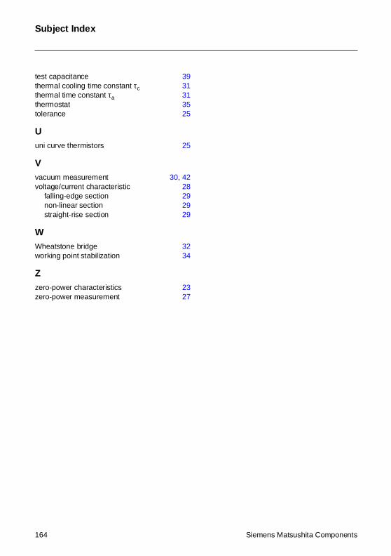
Subject Index
test capacitance 39thermal cooling time constant τc 31thermal time constant τa 31thermostat 35tolerance 25
Uuni curve thermistors 25
Vvacuum measurement 30, 42voltage/current characteristic 28
falling-edge section 29non-linear section 29straight-rise section 29
WWheatstone bridge 32working point stabilization 34
Zzero-power characteristics 23zero-power measurement 27
164 Siemens Matsushita Components