Climatix range - davidproduct.weebly.com products of the Climatix range are designed for use in...
18
CB1Q3900en_02 30.11.2009 Building Technologies s 3 900 Climatix TM Climatix range POL687.00/STD,POL687.70/STD POL635.00/STD,POL636.00/STD,POL638.00/STD POL985.00/STD, POL965.00/STD POL955.00/STD POL94U.00/STD, POL94E.00/STD POL945.00/STD, POL925.00/STD POL902.00/STD POL904.00/STD, POL906.00/STD POL907.00/STD, POL908.00/STD POL909.50/STD The products of the Climatix range are designed for use in ventilation, air conditioning, refrigeration and district heating plants. Powerful engineering and service tools are available to create ventilation, air conditioning and refrigeration applications and to facilitate commissioning.
-
Upload
duongduong -
Category
Documents
-
view
353 -
download
7
Transcript of Climatix range - davidproduct.weebly.com products of the Climatix range are designed for use in...

CB1Q3900en_02 30.11.2009 Building Technologies
s 3900
ClimatixTM
Climatix range POL687.00/STD,POL687.70/STD
POL635.00/STD,POL636.00/STD,POL638.00/STD
POL985.00/STD, POL965.00/STD
POL955.00/STD
POL94U.00/STD, POL94E.00/STD
POL945.00/STD, POL925.00/STD
POL902.00/STD
POL904.00/STD, POL906.00/STD
POL907.00/STD, POL908.00/STD
POL909.50/STD
The products of the Climatix range are designed for use in ventilation, air conditioning, refrigeration and district heating plants.
Powerful engineering and service tools are available to create ventilation, air conditioning and refrigeration applications and to facilitate commissioning.

2 / 18
Siemens Climatix range CB1Q3900en_02 Building Technologies 30.11.2009
Communication concept POL68X
Communication concept POL63X

3 / 18
Siemens Climatix range CB1Q3900en_02 Building Technologies 30.11.2009
Climatix 6XX products are designed for use in ventilation, air conditioning, refrig-eration and district heating plants and provide a broad range of control and moni-toring functions. The product range is of modular design and primarily comprises controllers (ver-sions with or without HMI) and different add-on I/O modules, including step motor and factory- or field-mounted communication modules. Different HMIs can be con-nected to the controllers, either directly (local HMI) or via the network (remote HMI). The controllers are freely programmable.
The Climatix controllers are freely programmable with the help of a powerful SAPRO software tool, thus saving time and effort in air conditioning, ventilation and refrigeration application development and testing. A superior commissioning tool called SCOPE is also available free of charge. A number of defined inputs / outputs (analog or digital) plus freely programmable I/O channels make it possible to create a host of applications with or without addi-tional modules to meet specific requirements. In fact, on-board I/O functionality does not suffice, a peripheral bus allows for connecting further local and remote I/O extension modules. The number and type of I/Os on the controller and extension modules are opti-mized for air conditioning, ventilation and refrigeration applications. On-board communication interfaces round off this scalable and intelligent control system. Additional communication modules can be added to the system in accordance with integration requirements.
The controllers can be operated with or without HMI – with the same functional-ity. The Climatix 6XX controllers offer an inbuilt HMI or an external local HMI (typi-cally mounted on metal panels). In addition, a remote HMI is available, operating on the process bus, with power supply and communication over the same 2 wires (using KNX TP1 technology) to optimize installation costs.
The additional I/O extension product range for connection via the peripheral bus comprises different I/O extension modules, some of them also with programmable channel configuration. Specific modules for step motor control are also available via the peripheral bus.
Using extension I/O modules, it is easy to design units with certain main funtionali-ties provided by a controller plus extension I/Os, and then have extra functionalities by adding other extension I/O modules according to needs.
This flexibility in HW combinations also allows modularity of electrical panel design, supported by a suitable concept of mechanical properties, communication and power supply possibilities available on all extension I/O modules Additional communication modules (BACnet/IP, BACnet/MSTP, LON, MBus, Mod-bus RS-485 and advanced programmable Web modules) extend the connectivity options of Climatix controllers, aimed at matching integration interface require-ments, or to povide specific servicing choices.
Climatix 600 range overview
Controllers
HMI
I/O product range
Communication modules

4 / 18
Siemens Climatix range CB1Q3900en_02 Building Technologies 30.11.2009
Climatix 6XX - product range
PO
L635
PO
L636
PO
L638
PO
L638
.7
PO
L687
.0
PO
L687
.7
PO
L985
PO
L965
PO
L955
PO
L945
PO
L94U
PO
L94E
PO
L925
Labe
ling
In /
Out
3 3 3 B In NTC inputX In NTC inputX In Digital input voltage freeX In DC O-5V inputX In Digital input voltage free
5 5 5 5 2 2 3 4 D In Digital input voltage free2 2 DU In Digital input 24V insulated2 2 2 1 1 1 2 DL In Digital input 115/230V insulated
X In Ni 1000 inputX In Pt 1000 inputX In NTC inputX In 0-2.5 kΩ inoutX In DC 0-5V inputX In DC 0-10V inputX In DC 0-20mA inputX In Digital input voltage free
max 6 max 6 max 6 max 6 X Out DC 0-10V analog outputmax 4 max 4 max 4 max 4 max 1 max 1 X Out DC 4-20mA analog output
max 4 max 4 max 4 max 4 max 4 max 4 max 4 max 4 max 2 max 2 X Out DC output digital output2 2 2 2 2 Y Out DC 0-10V analog output
1 1 M+/- Out Bipolar stepper motor output (4 wires)2 2 1 1 Q Out Relay output NO/NC
6 6 6 6 6 6 8 4 4 4 Q Out Relay output NO2 2 2 2 DO Out Triac output 0.5A
21 21 21 21 27 27 26 15 14 8 6 6 6 Total I/O amount2 2 2 2 2 2 2 2 1 1 24V DC 24V power supply terminals
2 2 2 2 1 1 1 5V DC 5V power supply terminals1 -- Inbuilt UPS (safe position at power off)
Yes Yes Yes Yes Yes Yes Freely programmableYes Yes T-HI Tool interface (USB on RJ45 connector)
Yes Yes Yes Yes T-SV Tool interface (USB Standard connector)Yes Yes Yes Yes Yes Yes T-HI User interface connector (RJ45)Yes Yes Yes Yes Yes Yes Modem service interface (RJ45)Yes Yes Yes Yes Yes Yes SD card supportYes Yes Yes Yes Yes Yes Real time clock (with battery holder)
Yes Yes Inbuilt user interface (164x44)Yes Yes Yes Yes T-IP IP service interface (with "HMI@Web")
Yes Yes Yes Yes Yes Yes Yes Yes Yes Yes Yes Yes Yes Peripheral Bus
Yes Yes Yes Yes Yes Yes Yes Yes Yes Yes Yes Yes COMM module interface1 1 1 1 1 1 Process Bus (KNX TP1 insulated)1 1 1 1 1 1 Internal KNX power supply (DPSU max 50mA)
2 1 1 RS485 insulated1 1 1 1 RS485 not insulated
1 1 LON port1 BACnet MSTP
1 BACnet IP1 Mbus
1 Advanced web server
Communication
PO
L902
PO
L904
PO
L906
PO
L907
PO
L908
PO
L909
Communication modules
Digital inputs
Outputs
Tools and commissioning
8 88 8 8 8
Max
Tot
al 8
Expansibility
Universal I/O(Siemens ASIC)
3 3
Sensor power supply
88 8
Controllers
2
I/O Extensions
Configurable inputs
Configurable inputs
2
NTC inputs

5 / 18
Siemens Climatix range CB1Q3900en_02 Building Technologies 30.11.2009
Climatix product range
POL687.00/
(refer to Data Sheet 3903)
POL687.70/ with HMI
(refer to Data Sheet 3903)
POL635.00/
(refer to Data Sheet 3230)
POL636.00/ with HMI
(refer to Data Sheet 3230)
POL638.00/ with HMI
(refer to Data Sheet 3230)
POL985.00/
(3221)
POL965.00/
(3222)
POL955.00
(3226)
POL94U.00/
(3225)
POL94E.00/
(3225)
POL945.00/
(3223)
POL925.00/
(3224)
POL895.00/ external HMI (3941)
POL902.00/
Modbus RS485
(3234)
POL904.00/
BACnet MSTP
(3232)
POL906.00/
LON
(3231)
POL907.00/
Mbus
(3236)
POL908.00/
BACnet IP
(3233)
POL909.00/
Advanced
Web (3235)
Controllers and HMIs
Extension modules
User interface
Communication modules

6 / 18
Siemens Climatix range CB1Q3900en_02 Building Technologies 30.11.2009
ACX93.00 SAPRO programming tool SCOPE commisioning tool
Connecting the components
Communication
module
Board-to-
board
connector
Controller with inbuilt HMI Board-to-
board
connector
Extension
module
Configuration example
Communication
module
Controller with HMI Extension modules
SW tools

7 / 18
Siemens Climatix range CB1Q3900en_02 Building Technologies 30.11.2009
Ordering data for accessories
Peripheral bus
Board-to-board Phoenix ZEC1,0/4-LPV-3,5 GY35AUC2CI1
Board-to-wire Phoenix ZEC1,0/4-ST-3,5 GY35AUC1R1,4
COMM interface
Board-to-board Phoenix ZEC1,0/10-LPV-3,5 GY35AUC2CI1
Accessories for controllers
Real time clock battery BR2032 POL 0B1.20/STD
PC service cable 150 cm POL 0C2.40/STD
SAPRO programming tool license ACX93.000
Test and demo case POL 0G6.87/STD
Connector set (spring cage, cable top entry )
POL 068.76/STD
1 x Phoenix FKCT 2,5/2-ST OG
1 x Phoenix FKCT 2,5/2-ST GY7035
6 x Phoenix FKCT 2,5/3-ST KMGY
1 x Phoenix FKCT 2,5/5-ST GY7035
1 x Phoenix FKCT 2,5/6-ST GY7035
1 x Phoenix FKCT 2,5/7-ST GY7035
2 x Phoenix FKCT 2,5/8-ST GY7035
Connector set (spring cage, cable side entry ) Available on request
1 x Phoenix FKCVW 2,5/2-ST OG
1 x Phoenix FKCVW 2,5/2-ST GY7035
6 x Phoenix FKCVW 2,5/3-ST GY7035
1 x Phoenix FKCVW 2,5/5-ST GY7035
1 x Phoenix FKCVW 2,5/6-ST GY7035
1 x Phoenix FKCVW 2,5/7-ST GY7035
2 x Phoenix FKCVW 2,5/8-ST GY7035
Connector set (screws, cable side entry ) Available on request
1 x Phoenix MVSTBW 2,5/2-ST OG
1 x Phoenix MVSTBW 2,5/2-ST GY7035
6 x Phoenix MVSTBW 2,5/3-ST GY7035
1 x Phoenix MVSTBW 2,5/5-ST GY7035
1 x Phoenix MVSTBW 2,5/6-ST GY7035
1 x Phoenix MVSTBW 2,5/7-ST GY7035
2 x Phoenix MVSTBW 2,5/8-ST GY7035

8 / 18
Siemens Climatix range CB1Q3900en_02 Building Technologies 30.11.2009
Connecting the extension modules
Specification for pheripheral bus cable and power supply: • If the total length of the pheripheral bus cable exceeds 3 m, shielded cables
must be used (L1 + L2 + Lx = >3 m)
• If the total length of the pheripheral bus cable is less than 3 m, shielded cables are not required (L1 + L2 + Lx = <3 m)
• Each shield must be grounded at one side only • Maximum bus cable length is 30 m (L1 + L2 + Ln = <30 m) • To connect the bus cable to the modules, use the board-to-wire terminals • GND of the power supply must be grounded (see illustration above) • Connections from one plant to another can be effected via a 2-wire bus cable
(A+ and B-). In this case, the modules must be powered by a separate supply (see illustration above). All plants must have the same GND. GND of the power supply must be grounded at one point only
• Refer to the pass-through-current rules for limiting the current across each de-vice within the individual limits
Cabling and grounding rules

9 / 18
Siemens Climatix range CB1Q3900en_02 Building Technologies 30.11.2009
Addressing the extension modules
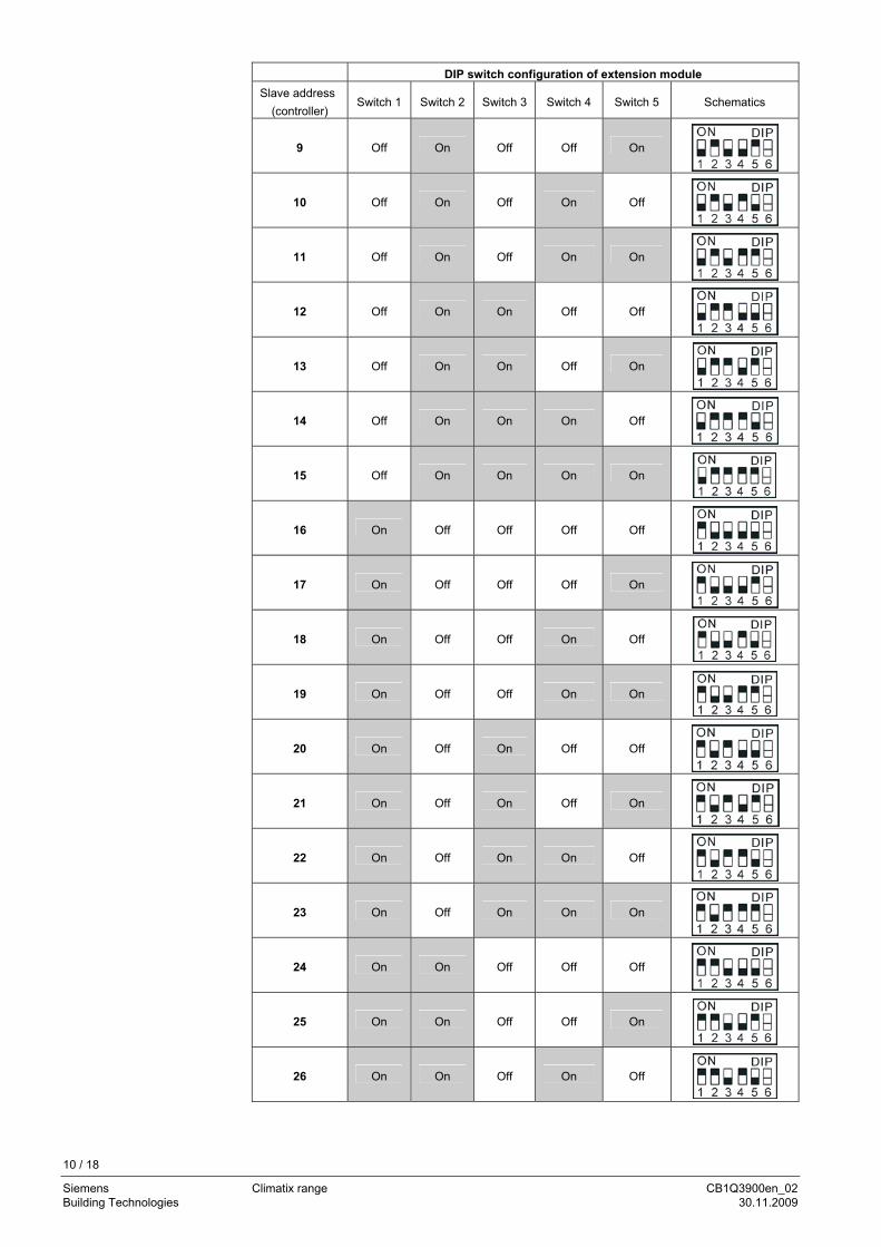
The extension modules are equipped with DIP switches for communication with the controller. Switches 1, 2, 3, 4, and 5 are configurable to set the slave address, while switch 6 acts as peripheral bus termination. When the extension module op-erates as the termination in the network, switch 6 must be set to ON.
By combining switches 1, 2, 3, 4 or 5, a maximum of 31 slave addresses can be configured. Below are some configuration examples:
DIP switch configuration of extension module
Slave address
(controller) Switch 1 Switch 2 Switch 3 Switch 4 Switch 5 Schematics
1 Off Off Off Off On
2 Off Off Off On Off
3 Off Off Off On On
4 Off Off On Off Off
5 Off Off On Off On
6 Off Off On On Off
7 Off Off On On On
8 Off On Off Off Off
DIP switches
10 / 18
Siemens Climatix range CB1Q3900en_02 Building Technologies 30.11.2009
DIP switch configuration of extension module
Slave address
(controller) Switch 1 Switch 2 Switch 3 Switch 4 Switch 5 Schematics
9 Off On Off Off On
10 Off On Off On Off
11 Off On Off On On
12 Off On On Off Off
13 Off On On Off On
14 Off On On On Off
15 Off On On On On
16 On Off Off Off Off
17 On Off Off Off On
18 On Off Off On Off
19 On Off Off On On
20 On Off On Off Off
21 On Off On Off On
22 On Off On On Off
23 On Off On On On
24 On On Off Off Off
25 On On Off Off On
26 On On Off On Off

11 / 18
Siemens Climatix range CB1Q3900en_02 Building Technologies 30.11.2009
DIP switch configuration of extension module
Slave address
(controller) Switch 1 Switch 2 Switch 3 Switch 4 Switch 5 Schematics
27 On On Off On On
28 On On On Off Off
29 On On On Off On
30 On On On On Off
31 On On On On On
The same address of extension module must be set in the application program of the controller. Zero cannot be set as the slave address.
Connecting the extension modules
The pass-through current is the maximum current that can flow across each device to limit the current within the defined safety levels. When extension modules are powered by a controller or some other extension module over the peripheral bus lines, a calculation is necessary to make certain that the total apparent power for this group of devices does not exceed 96 VA. If this is the case, the group of controllers and extension modules must be subdi-vided into 2 subgroups, enabling each of them to draw less than 96 VA. Note: When using AC 24 V power supply, power consumption is higher than that resulting from DC 24 V, the reason being the better efficiency of DC power supply. As a result, with DC 24 V power supply, the number of extension modules that can be connected to the same power supply line is greater than with AC 24 V. Maximum number of extension modules 31 (1…31)
Maximun pass-through current per group 96 VA
Cable lengths Total of max. 30 m
Below are some examples that show a number of choices: The following table provides the maximal capacity of the controllers, considering the full load configuration for each device. For this reason, the values used in other configurations can be smaller than those stated here.
Note
Pass-through current rules

12 / 18
Siemens Climatix range CB1Q3900en_02 Building Technologies 30.11.2009
Power consumption table for controllers and modules
Type Amount mA VA POL635.00 1800 22 Climatix 636 / 21 I/Os POL636.00 1800 22 Climatix 636 / 21 I/Os POL638.00 1800 22 Climatix 638 / 21 I/Os POL638.00 1800 22 Climatix 638 / 21 I/Os with inbuilt HMI POL687.00 1800 22 Climatix 687 / 27 I/Os POL687.70 1800 22 Climatix 687 / 27 I/Os with inbuilt HMI POL685.00 850 11 Extension module 26 I/Os POL965.00 750 10 Extension module 15 I/Os POL955.00 750 10 Extension module 14 I/Os POL94E.00 900 12 Extension module 6 I/Os - ECV POL94U.00 900 12 Ext. module 6 I/Os – ECV with inbuilt UPS
POL945.00 260 3 Extension module 8 I/Os POL925.00 150 1.5 Extension module 6 I/Os POL902.00 Communication Modbus RS-485 module POL904.00 Comm. Card BACnet MSTP POL906.00 Comm. Card LON POL908.00 Comm. Card BACnet IP POL909.00 Comm. Card Advanced Web POL895.50 Human Machine Interface (HMI)
Power supply AC 24 V DC 24 V
Maxiumum permissible power consumption per controller 96 VA 96 VA The HMIs and communication modules are powered by the controller anyhow and they do not affect the pass-through current (focus only on controller and extension I/Os for calculating the pass-through current). You find the pass-through current simulator below.

13 / 18
Siemens Climatix range CB1Q3900en_02 Building Technologies 30.11.2009
Pass-through current simulator
24Vac 24VdcmA W
Required nr. of POL635.00 1800 22 Climatix 635 - 21 IOsRequired nr. of POL636.00 1800 22 Climatix 636 - 21 IOsRequired nr. of POL638.00 1800 22 Climatix 638 - 21 IOsRequired nr. of POL638.70 1800 22 Climatix 638 - 21 IOs - with inbuilt HMIRequired nr. of POL687.00 1800 22 Climatix 687 - 27IOsRequired nr. of POL687.70 1800 22 Climatix 687 - 27IOs - with inbuilt HMIRequired nr. of POL985.00 850 11 Extension 26 IOsRequired nr. of POL965.00 750 10 Extension 15 IOsRequired nr. of POL955.00 750 10 Extension 14 IOsRequired nr. of POL94E.00 900 12 Extension 6 IOs - ECVRequired nr. of POL94U.00 900 12 Extension 6 IOs - ECV with inbuilt UPSRequired nr. of POL945.00 260 3 Extension 8 IOsRequired nr. of POL925.00 150 1,5 Extension 6 IOsRequired nr. of POL902.00 Comm. Card Modbus RS485Required nr. of POL904.00 Comm. Card BACnet MSTPRequired nr. of POL906.00 Comm. Card LONRequired nr. of POL908.00 Comm. Card BACnet IPRequired nr. of POL909.00 Comm. Card Advanced WebRequired nr. of POL895.50 Human Machine Interface
24Vac 24Vdc0,00 0,000,00 0,00
Power supply type
Pass-through current calculator for Power Supply AC 24V or DC 24V
Max 96VA for both AC 24V or DC 24V power supplies
Sum of CurrentsPower supply type
Total Appartent Power [VA]
Fill in your data!

14 / 18
Siemens Climatix range CB1Q3900en_02 Building Technologies 30.11.2009
This example shows how to use one POL687.70 controller together with 2 POL965, 2 POL954 and 2 POL94U extension modules. This combination is not possible with only one AC 24 V power supply, since the total apparent power ex-ceeds 96 VA (note that it could be done using DC 24 V).
Power supply AC 24 V DC 24 V
mA W Required nr. of POL635.00 1800 22 Climatix 635 - 21 I/Os Required nr. of POL636.00 1800 22 Climatix 636 - 21 I/Os
Required nr. of POL638.00 1800 22 Climatix 638 - 21 I/Os Required nr. of POL638.70 1800 22 Climatix 638 - 21 I/Os - with inbuilt HMI Required nr. of POL687.00 1 1800 22 Climatix 687 - 27 I/Os
Required nr. of POL687.70 1800 22 Climatix 687 - 27 I/Os - with inbuilt HMI Required nr. of POL985.00 850 11 Extension 26 I/Os Required nr. of POL965.00 2 750 10 Extension 15 I/Os
Required nr. of POL955.00 750 10 Extension 14 I/Os Required nr. of POL94E.00 2 900 12 Extension 6 I/Os - ECV Required nr. of POL94U.00 900 12 Extension 6 I/Os - ECV with inbuilt UPS
Required nr. of POL945.00 2 260 3 Extension 8 I/Os Required nr. of POL925.00 150 1.5 Extension 6 I/Os Required nr. of POL902.00 Communication card Modbus RS485
Required nr. of POL904.00 Communication card BACnet MSTP Required nr. of POL906.00 Communication card LON Required nr. of POL908.00 Communication card BACnet IP
Required nr. of POL909.00 Communication card advanced Web Required nr. of POL895.50 Human Machine Interface
Power supply AC 24 V DC 24 V
Sum of currents 5.62 3.00
Total apparent power [VA] 134.88 72.00
Example with two AC 24 V power supplies:

15 / 18
Siemens Climatix range CB1Q3900en_02 Building Technologies 30.11.2009
So we split the group into subgroup 1 and subgroup 2
Pass-through current calculator for each power supply
mA W
Required nr. of POL635.00 1800 22
Required nr. of POL636.00 1800 22
Required nr. of POL638.00 1800 22
Required nr. of POL638.70 1800 22
Required nr. of POL687.00 1800 22
Required nr. of POL687.70 1 1800 22
Required nr. of POL985.00 850 11
Required nr. of POL965.00 1 750 10
Required nr. of POL945.00 1 260 3
Required nr. of POL925.00 150 1.5
Required nr. of POL94E.00 900 12
Required nr. of POL94U.00 1 900 12
Required nr. of POL902.00
Required nr. of POL904.00
Required nr. of POL906.00
Required nr. of POL908.00
Required nr. of POL909.00
Required nr. of POL895.50
Power supply AC24V DC24V
Sum of currents 3.71 1.96
Total apparent power [VA] 89.04 47.00
Pass-through current calculator for each power supply
mA W
Required nr. of POL635.00 1800 22
Required nr. of POL636.00 1800 22
Required nr. of POL638.00 1800 22
Required nr. of POL638.70 1800 22
Required nr. of POL687.00 1800 22
Required nr. of POL687.70 1800 22
Required nr. of POL985.00 850 11
Required nr. of POL965.00 1 750 10
Required nr. of POL945.00 1 260 3
Required nr. of POL925.00 150 1.5
Required nr. of POL94E.00 900 12
Required nr. of POL94U.00 1 900 12
Required nr. of POL902.00
Required nr. of POL904.00
Required nr. of POL906.00
Required nr. of POL908.00
Required nr. of POL909.00
Required nr. of POL895.50
Power supply AC24V DC24V
Sum of currents 1.91 1.04
Total apparent power [VA] 45.84 25.00 Result of example with two AC 24 V power supplies

16 / 18
Siemens Climatix range CB1Q3900en_02 Building Technologies 30.11.2009
Power supply AC24V DC24V
mA W Required nr. of POL635.00 1800 22 Climatix 635 - 21 I/Os
Required nr. of POL636.00 1800 22 Climatix 636 - 21 I/Os Required nr. of POL638.00 1800 22 Climatix 638 - 21 I/Os Required nr. of POL638.70 1800 22 Climatix 638 - 21 I/Os - with inbuilt HMI
Required nr. of POL687.00 1800 22 Climatix 687 - 27 I/Os Required nr. of POL687.70 1 1800 22 Climatix 687 - 27 I/Os - with inbuilt HMI Required nr. of POL985.00 850 11 Extension 26 I/Os Required nr. of POL965.00 4 750 10 Extension 15 I/Os Required nr. of POL955.00 750 10 Extension 14 I/Os Required nr. of POL94E.00 900 12 Extension 6 I/Os - ECV
Required nr. of POL94U.00 4 900 12 Extension 6 I/Os - ECV with inbuilt UPS Required nr. of POL945.00 2 260 3 Extension 8 I/Os Required nr. of POL925.00 150 1.5 Extension 6 I/Os
Required nr. of POL902.00 Communication card Modbus RS-485 Required nr. of POL904.00 Communication card BACnet MSTP Required nr. of POL906.00 Communication card LON
Required nr. of POL908.00 Communication card BACnet IP Required nr. of POL909.00 Communication card advanced Web Required nr. of POL895.50 Human Machine Interface
Power supply AC24V DC24V
Sum of currents 8.92 4.83
Total apparent power [VA] 214.08 116.00
Max. 96 VA for both AC 25 V or DC 24 V power supplies
Example with two DC 24 V power supplies:

17 / 18
Siemens Climatix range CB1Q3900en_02 Building Technologies 30.11.2009
So we split the group into subgroup 1 and subgroup 2
Pass-through current calculator for each power supply
mA W
Required nr. of POL635.00 1800 22
Required nr. of POL636.00 1800 22
Required nr. of POL638.00 1800 22
Required nr. of POL638.70 1800 22
Required nr. of POL687.00 1800 22
Required nr. of POL687.70 1 1800 22
Required nr. of POL985.00 850 11
Required nr. of POL965.00 2 750 10
Required nr. of POL945.00 1 260 3
Required nr. of POL925.00 150 1.5
Required nr. of POL94E.00 900 12
Required nr. of POL94U.00 2 900 12
Required nr. of POL902.00
Required nr. of POL904.00
Required nr. of POL906.00
Required nr. of POL908.00
Required nr. of POL909.00
Required nr. of POL895.50
Power supply AC24V DC24V
Sum of currents 5.36 2.88
Total apparent power [VA] 128.64 69.00
Pass-through current calculator for each power supply
mA W
Required nr. of POL635.00 1800 22
Required nr. of POL636.00 1800 22
Required nr. of POL638.00 1800 22
Required nr. of POL638.70 1800 22
Required nr. Of POL687.00 1800 22
Required nr. of POL687.70 1800 22
Required nr. of POL985.00 850 11
Required nr. of POL965.00 2 750 10
Required nr. of POL945.00 1 260 3
Required nr. of POL925.00 150 1.5
Required nr. of POL94E.00 900 12
Required nr. of POL94U.00 2 900 12
Required nr. of POL902.00
Required nr. of POL904.00
Required nr. of POL906.00
Required nr. of POL908.00
Required nr. of POL909.00
Required nr. of POL895.50
Power supply AC24V DC24V
Sum of currents 3.56 1.96
Total appartent power [VA] 85.44 47.00 Result of example with two DC 24 V power supplies

18 / 18
Siemens Climatix range CB1Q3900en_02 Building Technologies 30.11.2009
2009 Siemens Switzerland Ltd. Subject to change