Novel mechatronic solutions incorporating inerters for ... · Loughborough University Institutional...
25
•
Transcript of Novel mechatronic solutions incorporating inerters for ... · Loughborough University Institutional...
Loughborough UniversityInstitutional Repository
Novel mechatronic solutionsincorporating inerters forrailway vehicle verticalsecondary suspensions
This item was submitted to Loughborough University's Institutional Repositoryby the/an author.
Citation: MATAMOROROS-SANCHEZ, A. and GOODALL, R., 2015. Novelmechatronic solutions incorporating inerters for railway vehicle vertical sec-ondary suspensions. Vehicle System Dynamics, 53 (2), pp.113-136.
Additional Information:
• This is an Accepted Manuscript of an article published by Taylor &Francis in `Vehicle System Dynamics' on 08/12/2014, available online:https://doi.org/10.1080/00423114.2014.983529.
Metadata Record: https://dspace.lboro.ac.uk/2134/27064
Version: Accepted for publication
Publisher: c© Taylor & Francis
Rights: This work is made available according to the conditions of the Cre-ative Commons Attribution-NonCommercial-NoDerivatives 4.0 International(CC BY-NC-ND 4.0) licence. Full details of this licence are available at:https://creativecommons.org/licenses/by-nc-nd/4.0/
Please cite the published version.

19th July 2014 14:33 Vehicle System Dynamics VSD˙Hybrid-Inerter-Suspensions-reviewed072014-Sec4c
Vehicle System DynamicsVol. 00, No. 00, February 2014, 1–24
RESEARCH ARTICLE
Novel mechatronic solutions incorporating inerters for railway
vehicle vertical secondary suspensions
Alejandra Z. Matamoros-Sancheza ∗, Roger M. Goodallb
aEngineering Faculty, Universidad de Los Andes, Merida 5101, Venezuela;bDepartment of Electronic, Electrical and Systems Engineering, Loughborough University,
Loughborough, LE11 3TU, UK
(v3.5 released June 2008)
This paper discusses the effects of inerter-based passive networks in the design of novel mechat-ronic solutions for improving the vertical performance of a bogied railway vehicle. Combina-tions of inerter-based structures and active suspensions comprise distinct novel mechatronicsolutions for the vertical secondary suspension of the vehicle. The parameters of the active andpassive parts of the overall configuration are optimised so that a synergy arises to enhance thevehicle vertical performance and simplify common mechatronic suspension design conflicts.The study is performed by combining inerter-based suspensions with well established activecontrol (output-based and model-based) strategies for ride quality enhancement. Also, a novelnonlinear control strategy, here called ‘Adaptive Stiffness’, is incorporated for suspension de-flection regulation to complement the well known local implementation of skyhook damping.This would complete a significant set of control strategies to produce general conclusions. Thevehicle performance is assessed through the vertical accelerations of the vehicle body as aninitial investigation. Attained results show the potential of the inerter concept for innovatingmechatronic technologies to achieve substantial improvements in railway vehicle vertical ridequality with reduced actuator force.
Keywords: inerter; passive suspension; active suspension; railway vehicle; mechanicalcontrol; hybrid suspension
1. Introduction
The classification of vehicle suspensions –and vehicle dynamics control in the samecontext– involves a number of different criteria. Some suspension solutions do notneed external power supplies, such as passive and semi-active (the former havingfixed characteristics as opposed to the latter for which the characteristic can berapidly varied by electronic controllers), whereas others do need an external powersupply, known as active or full-active (see [1]). Therefore, according to the controllaw designed for the full-active suspensions, energy can flow in or out of the dynamicsystem. Suspension systems in the secondary layer are studied in this paper withparticular focus on the design of hybrid –novel mechatronic passive-plus-active–suspensions for vertical ride quality enhancement.
Fijalkowski discussed in [2] about hybrid suspensions in automotive, and Smith etal. in [2] on optimisation for vibrating structures. The common and main objectiveof combined suspensions is to reduce power demands and actuator size in terms
∗Corresponding author. Email: [email protected]
ISSN: 0042-3114 print/ISSN 1744-5159 onlinec© 2014 Taylor & FrancisDOI: 10.1080/0042311YYxxxxxxxxhttp://www.informaworld.com

19th July 2014 14:33 Vehicle System Dynamics VSD˙Hybrid-Inerter-Suspensions-reviewed072014-Sec4c
2 Taylor & Francis and I.T. Consultant
of maximum forces requirements (see, for example, Corriga et al. [3] and Guiaet al. [4]). Some work has been done in this direction for suspension systems ingeneral, by supplementing the actuators with simple arrangements of springs anddampers, or even redesigning the system parameters to constitute the passive partof the suspension as in [2]. In general however, reduced actuator size also results inreduced power demands and energy consumption, but practically these are small interms of total power/energy requirements for a railway vehicle. In addition, fittingan actuator into a suspension is often practically tricky, and so this paper’s focusis upon reducing actuator force and size.
Moreover, for railway suspensions, most of the applications of mechatronic sus-pensions have been investigated to work together with the conventional passivesuspensions [5, 6]. These may be further aided by springs in the modification ofthe actuator bandwidth, for example, when considering real actuator dynamics[7]. However, no attempt to create cooperation between inerter-based suspensionsand active suspensions has been found in the literature. The only previous workon developing mechatronic solutions using the inerter concept are the mechatronicnetwork systems proposed by Wang and Chan for the synthesis of high-order andswitching impedances [8–11].
After the introduction of the inerter by Smith in 2002 [12], a number of re-search studies have demonstrated enhancement in vehicle dynamics through theuse of mechanical passive control complemented by the inerter concept [13, 14].The inerter was conceived as a two-terminal mechanical element characterised fordeveloping a linear force which is proportional to the relative acceleration acrossthe terminals. The invention has led to passive control accomplishment throughnovel —inerter-based— mechanical devices [15–19], with success implementationin racing cars [20]. In particular for railway vehicles, the use of inerter-based passivenetworks has proven benefits for ride quality and stability enhancement [21–26].Nevertheless these mechanical networks define, from the control viewpoint, a com-pensator structure which is still limited compared with the control laws that arerealisable via active suspensions.
Mechatronic solutions are emerging as one of the important sources of innovationfor future generations of railway vehicles [27], and a worldwide operational exampleof using mechatronics is the tilting train. There has been also a growing consensusabout the future use of active control to improve railway vehicles’ running be-haviour through new technologies in the primary suspensions. However, differentproposed solutions are still in the experimental stage. Progress on concepts formechatronic secondary suspensions is likewise well advanced, although the bene-fits attained so far are yet unconvincing for the railway industry [27]. Therefore,research interests continue.
As a contribution to the field of railway vehicle secondary suspension develop-ment, this study is supported by the following facts, together with the novelty ofthe inerter concept for passive mechanical control:
(1) It is still necessary to find a solution whose benefits justify the investmentsin the involved technology,
(2) The vertical dynamic is a relatively simple case of study in railway vehiclesfor a first investigation on the potential of the inerter within integratedtechnologies.
(3) Passive suspensions consisting of springs, dampers and inerters could se-lectively compensate for resonant frequencies of the sprung mass dynamics,as opposite to spring-damper conventional suspensions. This may reduceactive force requirements in active suspensions.

19th July 2014 14:33 Vehicle System Dynamics VSD˙Hybrid-Inerter-Suspensions-reviewed072014-Sec4c
Vehicle System Dynamics 3
βb1zb1Ob1βb2
zb2Ob2
βv
zvOv
OR
v
lvlv
lb lb
Figure 1. Side-view multibody representation of a railway vehicle with detail on the local coordinates andbodies DoF.
In particular, this scientific paper addresses the analysis and design of ideal hy-brid suspensions consisting of conventional mechatronic systems — active control—augmented by inerter-based devices —passive control. The idea here is to accom-plish cooperative control in the vehicle secondary suspension for enhancing verticalride quality with optimal actuator force requirements. Simplified theoretical mod-els of the vehicle are used to reveal the principal benefits arising from the inerterconcept.
2. Mathematical model of a railway vehicle with conventional suspensions
As this work concerns the vertical ride quality, mathematical modelling of the ver-tical and pitch modes of the bogied railway vehicle for decentralised control designis considered. The model describes the dynamics of a single vehicle. Detailed geo-metry of the vehicle bodies, aerodynamic factors, body flexibilities, non-linearitiesof the wheel/rail interaction forces, are some of the engineering aspects not accoun-ted for in the model. Moreover, for assessment of bounce and pitch modes only,the model constrains the lateral, yaw and roll motions of the vehicle given thesignificant decoupling with the corresponding modes. The longitudinal dynamic isassumed stationary at a nominal travelling speed. This turns the representationinto a planar model of the bogied —two-suspension layer— vehicle.
Thus, the model used throughout this paper is a linear incremental model withrespect to the vehicle’s equilibrium condition fixed to the local coordinates originOv, Ob1, and Ob2 from Figure 1. It is written in the Laplace transformed domainas
s2mv zv = Fa1 + Fa2 + Fu1 + Fu2
s2Ivyβv = lv
(Fa1 − Fa2 + Fu1 − Fu2
)s2mbzb, i = −Fa, i − Fu, i + Fp, i, (2i−1) + Fp, i, 2i
s2Ibyβb, i = lb
(Fp, i, (2i−1) − Fp, i, 2i
)(1)
where the symbol ˆ denotes Laplace transform, Fp, i, j and Fa, i are, respectively, theforces applied by the conventional primary and secondary suspension, and Fu, i thecontrol forces applied by the novel mechatronic secondary suspension. The free-body diagram of the vehicle body and the bogies are supplied in Figure 2, andgeometrical, mass and inertia parameter specifications are contained in Table 1.

19th July 2014 14:33 Vehicle System Dynamics VSD˙Hybrid-Inerter-Suspensions-reviewed072014-Sec4c
4 Taylor & Francis and I.T. Consultant
Fa1 Fu1 Fa2 Fu2
zv
βv
lv lv
mv , Ivy
(a) Free-body diagram for thevehicle body.
−Fa,i −Fu,i
Fp,i,(2i−1) Fp,i,2i
zb,i
βb,i
lb lb
mb, Iby
(b) Free-body diagram for the i-thvehicle bogie.
Figure 2. Free-body diagrams for the vehicle main bodies.
Table 1. Parameter values for the Side-View model (adapted from [5] for high
damping airsprings [28].)
Sym. Parameter Value
mv Vehicle body mass [kg] 38× 103
mb Bogie mass [kg] 2.5× 10³
Ivy Vehicle pitch inertia[kgm2
]2.31× 10⁶
Iby Bogie pitch inertia[kgm2
]2× 10³
lv Semi-longitudinal spacing of secondary suspension [m] 9.5lb Semi-longitudinal spacing of wheelsets [m] 1.25ka Change of area stiffness (×2)
[Nm−1
]3.13× 10⁵
ks Airspring stiffness (×2)[Nm−1
]1.24× 10⁶
kr Reservoir stiffness (×2)[Nm−1
]4.88× 10⁵
cr Airspring damping (×2)[Nsm−1
]1× 10⁵
kp Primary suspension stiffness(×2)[Nm−1
]5× 10⁶
cp Primary suspension damping (×2)[Nsm−1
]3.58× 10⁴
v Vehicle speed[ms−1
]55
Symmetry about the longitudinal axis is considered for the planar model. Thus,side suspensions are concentrated in a planar suspension model by duplicating(×2) the suspension parameters.
ka
ks
kr cr
zv
zb
Figure 3. Nishimura model for the conventional secondary suspension.
2.1. Conventional suspension models
Two stages of suspension compose a typical railway vehicle, as already shown inFigure 1. Conventionally, these comprise stiff springs and dampers in the primarysuspension stage, and airsprings in the secondary. Whilst the primary suspensionmodel is fairly simple, the model for the airsprings in the secondary suspensionis more complicated due to the frequency-dependent behaviour they exhibit. Infact, there is still not consensus on the most appropriate airspring model; as areference, Bruni et al. offer a review on some existing models in [29]. This paperconsiders the one-dimensional models of the primary and secondary suspensionsfrom [21], where the Nishimura model is used (Figure 3). We make assumptionsof high damping coefficient for the airsprings. Hence, internal resonances due tothe fluid inertance of the accelerated air in the air bag-reservoir interchange phaseare negligible, justifying the appropriateness of the chosen model [28]. Thus, for

19th July 2014 14:33 Vehicle System Dynamics VSD˙Hybrid-Inerter-Suspensions-reviewed072014-Sec4c
Vehicle System Dynamics 5
the railway vehicle in Figure 1 the force applied by the j-th primary suspension isgiven by
Fp, i, j = Yp(s) s(zw, j −
(zb, i + (−1)j−1 lbβb, i
))(2)
where j = 1, 2 (j = 3, 4) is restricted to i = 1 (i = 2) and identifies, respectively,the front and rear suspensions and track inputs of the leading (trailing) bogie.Similarly, the i-th airspring force is given by
Fa, i = Ya(s) s(zb, i −
(zv + (−1)i−1 lvβv
))(3)
where i = 1 and i = 2 identify, respectively, the front and rear airsprings and bogies.For this, the admittance functions of the primary and secondary suspensions arewritten as:
Yp(s) =(kps−1 + cp
)Ya(s) =
s γc + γks (s+ α)
(4)
with: γc = ks + ka, γk = ks(kr+ka)+krkacr
, and α = ks+krcr
. The description and valueof the conventional vehicle side-view model parameters are listed in Table 1.
2.2. Track models for suspension design
The moving irregularity model from [21] representing a nominal track is used herefor assessment of the vertical ride quality. In [21], the irregularity rate δz is de-scribed as a white random stationary process with a Gaussian distribution whichis dependent on the vehicle’s travelling speed. Even though the ‘infinite’ connota-tion results slightly unrealistic for a real track, this simplification is yet valid anduseful for suspension design purposes (see for example [5] for a comparison withrealistic data and a fourth order spatial power spectrum best fit model). Hence,
the p.s.d. of the track elevation rate in the time frequency, S δzt (ωt), for a speed vand vertical roughness coefficient Ωz, can be written as
S δzt (ωt) = 2πΩz v[(m/s)2 (rad/s)−1
](5)
(Ωz = 2.5 × 10⁻⁷ [m] is a typical value for a good quality track [5, 30–32] and isused throughout this paper). Nevertheless, to prevent unrealistic numerical results
because of the flat spectrum of S δzt (ωt), a first order low-pass filter with cornerfrequency of 20 [Hz] of the track input in Equation 5 is introduced.
In active suspension design, special attention should be given to the suspensiondeflection due to clearance limitations and to the maximum active forces acceptablefor the actuator. If this deterministic requirement is not accounted for, unrealisticactive suspension strategies may arise, especially those based upon the skyhookdamping concept [33]. A typical deterministic profile producing worst case condi-tions for those physically constrained variables is a railway gradient fwz(t) with asuperimposed acceleration limit in the transition of 0.4 [ms−2] (i.e. of approxim-ately 4 [%g]) for a nominal speed of 55 [ms−1], resulting in a transitional section of

19th July 2014 14:33 Vehicle System Dynamics VSD˙Hybrid-Inerter-Suspensions-reviewed072014-Sec4c
6 Taylor & Francis and I.T. Consultant
1 [s] [5, 34]. Thus,
fwz(t) = 0.4
t∫−∞
(1 (τ1 − t0)− 1 (τ1 − (t0 − 1))) dτ1 [ms−1] (6)
3. Objectives and challenges in mechatronic suspension design
The ultimate objective for the vertical secondary suspensions of a railway vehicleis the enhancement of passengers’ ride experience, besides providing adequate sup-port to the vehicle cabin. Ride characteristics are assessed in this paper by compu-tation of the vehicle body root-mean-square (r.m.s.) leading, middle and trailingaccelerations yzv:
yzv =[zv + lvβv zv zv − lvβv
]T [ms−2
]These are adopted as ride quality penalisation indices reunited in the vector J1,
presented in percentage of gravity units:
J1 =[J1L J1M J1T
]T[%g]
where the sub-indices L, M, T stand for leading, middle and trailing positions, re-spectively. For this, considerations of a straight track and constant running speedare made [5, 6, 31, 32]. Unweighted accelerations were decided for this study, follow-ing recent research showing that the standard norms typically used to determineride comfort indices (e.g. ISO 2631 [35], the Sperling’s method [36], or ENV 12299[37]) underestimate the effects of vibrations on the passengers’ normally sedent-ary activity (e.g. writing, reading, sketching, working with laptops) [38–40]. Thisconsideration would avoid hiding the effects of the inerter on the mechatronic struc-tures and the vehicle performance. Future studies will adopt the standard normsto set further conclusions on the potential of the proposed synergy.
In the design of railway vehicle suspensions for ride quality enhancement, im-proving the measurement at the most unfavourable location on the vehicle bodyis a common sense practice followed here. This is achieved by minimising the leastride quality penalisation index, J1
sup, calculated for the vehicle response to thetrack irregularities described in Equation 5. For the case of incorporating mechat-ronic suspensions with linear dynamical characteristics only, J1 is obtained as the
mean-square of the zero-mean stationary process yzv(t), E[yzv(t) yzv(t)T ]. The lat-
ter, which is also equivalent to the autocorrelation function of yzv(t), is calculatedby using the state-space method based on the solution of the Lyapunov stabilityequation for the stationary process. An alternative to this, was to use the spectraldensity Syzvt (ω) from frequency-based analysis. Differently, for the vehicle with anonlinear control strategy in the mechatronic suspension, calculation of J1 reliesonly on the r.m.s. value of the output data obtained from simulations.
Further, some physical constraints conflict with the achievement of high levels ofride quality. In particular, special attention is given here to the trade-off betweenride quality, secondary suspension deflection, and active force magnitude. The re-ferred characteristics are assessed in the suspension deflection and active forceindices, J2 and J3, respectively. Also, mean power consumption could be easily as-

19th July 2014 14:33 Vehicle System Dynamics VSD˙Hybrid-Inerter-Suspensions-reviewed072014-Sec4c
Vehicle System Dynamics 7
sessed for an idealised actuator using P = E [Fc (z2 − z1)] for the stochastic meanpower as in [28], and P = Fc (z2 − z1) for consumption due to deterministic trackfeatures. However, the true power and thus energy consumption will be affectedsignificantly by the choice of actuator technology, and in practice energy consump-tion for an active suspension has been shown to be small in the context of thewhole train. Hence, for the purposes of this paper we do not assess energy indices.
• Suspension deflection index, J2: For the suspension deflection vector
zD(t) =[zvb1(t) zvb2(t)
]T=[zb1 − (zv + lvβv) zb2 − (zv − lvβv)
]T (7)
where zvb1 and zvb2, are respectively, the deflection of the leading and trailingsuspensions, the performance index J2 is defined following the three-sigma ruleas
J2 = maxi=1, 2
[MD, i + 3σD, i] (8)
where MD, i is the i-th entry of the vector
MD =[
maxfwz, t>0
|zvb1(t)| maxfwz, t>0
|zvb2(t)|]T
(9)
which is the vector of the maximum deflection of the leading and trailing second-ary suspensions developed during the transitional response to the deterministictrack input fwz. Moreover, σD, i in Equation 8 is the root-mean-square of theentries of zD in response to the stochastic track irregularities δz(t) and is calcu-lated by using the same methods described for ride quality assessment. A typicalvalue for the maximum allowable suspension deflection index J2 is 3.5 [cm] [5].
• Active force index, J3: Similarly to the calculation of J2, for the active forcesdemanded by the control systems of the leading and trailing suspensions, FcL(Fc1) and FcT (Fc2), respectively,
Fc(t) =[FcL(t) FcT (t)
]T=[Fc1(t) Fc2(t)
]T(10)
the performance index J3 is defined as
J3 = maxi=1, 2
[MFc, i + 3σFc, i] (11)
where MFc, i is the i-th entry of the vector
MFc =[
maxfwz, t>0
|zFc1(t)| maxfwz, t>0
|zFc2(t)|]T
(12)
which is the vector of the maximum peak force required by the control systemsto the leading and trailing actuators during the transitional response to thedeterministic track input, fwz. σFc, i is the root-mean-square of Fc, i in responseto the stochastic track irregularities and is calculated by using the same methodsdefined before for ride quality assessment.

19th July 2014 14:33 Vehicle System Dynamics VSD˙Hybrid-Inerter-Suspensions-reviewed072014-Sec4c
8 Taylor & Francis and I.T. Consultant
Actuators Controllers
Active Forces
Passive Forces
Measurements
Suspension Velocity
Vehicle Dynamics
Novel Mechanical Devices
Track inputs
Power supply
Figure 4. General scheme of the integrated suspension.
4. Novel mechatronic suspensions incorporating inerters
From the control perspective, the design of passive suspensions using inerters (e.g.mechanical, hydraulic) is supported on passive linear control and mechanical net-work theory. Incorporating inerters to a passive suspension enables the implement-ation of mechanical networks with resonant and selective compensating features;that is, the poles of a spring-damper-inerter network admittance function can becomplex [12]. Active solutions, on the other hand, are commonly designed by choos-ing from an extensive range of appropriate control strategies, which could in fact in-clude compensation structures such as those synthesised by using springs, dampersand inerters. These rely upon the system’s input and output ports as well as oninherent constraints, e.g. the available measurements, the location of the actuators,and the action/reaction condition for the application of the controlled forces. Inorder to be able to evaluate the quality of the innovative technology researchedhere, the control strategies required meticulous selection and formulation whileexcluding these which could be implemented by passive networks. With this, weaim to study the potential of using passive compensation for reducing active forcestowards a cooperative hybrid control.
The investigation on the synergy expected from the mechatronic suspensionsusing inerters starts with the integration of active and passive configurations asdepicted in the general block diagram from Figure 4. The novel mechatronic struc-tures will produce i-th integrated forces in parallel to the front (i = 1) and rear(i = 2) airsprings of the form
Fu, i = Fpn, i + Fc, i (13)
where: Fpn, i is the force applied by the inerter-based device (i.e. the passive partof the mechatronic suspension), and Fc, i is the force applied by an ideally perfectactuator (i.e. the active part of the mechatronic suspension). Candidate structuresof the passive networks and the active control strategies, together producing Fu, i,are described in the following.

19th July 2014 14:33 Vehicle System Dynamics VSD˙Hybrid-Inerter-Suspensions-reviewed072014-Sec4c
Vehicle System Dynamics 9
k1k1
c1
c1
b1
b1
b2
kaka
ksksks
krkrkr crcrcr
S0Airspring
S0//S1 S0//S2
Figure 5. Passive suspensions: Conventional passive suspension S0 (airspring) with inerter-based candidatelayouts Si in parallel (for i the structure identifier).
4.1. Candidate inerter-based passive suspensions
Mechanical and hydraulic inerter devices with equivalent models in mechanical net-works comprising ideal springs, dampers and inerters were chosen for this study.Figure 5 contains the layouts Sn of the equivalent inerter-based networks. A mech-anical network defined this way, is linearly characterised by its admittance functionYpn(s) and thus, can be said to develop passive forces in response to the relativevelocity of the network terminals, i.e.
Fpn, i = Ypn(s) s(zb, i −
(zv + (−1)i−1 lvβv
))(14)
with the sub-index ‘i’ (with i = 1, 2) identifying the front and rear suspensionsand bogies.
The mechanical structures in Figure 5 are composed by the conventional airspringmechanical model S0 and the inerter-based network layout Sn, with n the structureidentifier (notice that S1 and S2 look bold in the figure). The spring k1 commonto the layouts, implicitly includes the end-stiffness ke of the bushes that wouldbe attached to both ends of the novel device and the vehicle body and bogies(typically, ke = 3.5× 10⁶
[Nm−1
]and thus k1 ≤ 3.5× 10⁶
[Nm−1
]).
Layout S1 is an equivalent for a mechanical inerter device [12, 15]. The networkmodel includes parasitic damping/friction and stiffness effects of the device, re-spectively, in c1 and k1. Sensible parameter values for the parasitic effects for theinerter sizes we use here are around c1 = cb1 = 1×10⁴
[Nsm−1
], and k1 = kb1 = ke.
It is worth noting, however, that the parasitic effects of a mechanical inerter itself,in terms of damping (or frictions) and stiffnesses, depend on the physical imple-mentation of the inerter device. We consider this single case only. Furthermore, wedecided not to constrain c1 and k1 to cb1 and kb1 (the coefficients for modellingthe parasitic effects [15]), respectively, but instead to include them with the setof design parameters. This converts S1 in a spring-damper-inerter mechanical net-work with free stiffness, damping an inertance parameters. That enables a moreexpanded view of the inerter potential as an element of more complex mechanicaldevices. Layout S2, on the other hand, corresponds to one of the embodimentspresented with the damping and inertial hydraulic device invention ([16]–Figures16 and 20), with end-stiffness modelled in series.

19th July 2014 14:33 Vehicle System Dynamics VSD˙Hybrid-Inerter-Suspensions-reviewed072014-Sec4c
10 Taylor & Francis and I.T. Consultant
4.2. Control strategies for the active suspensions
Figure 6 shows a classification of the active control strategies chosen in this paperfor vertical ride quality enhancement, which also considers the conflicts commonlyarising in mechatronic control design. The first level of the diagram identifies activeand passive strategies for ride quality enhancement, with the latter directly asso-ciated to mechanical networks including inerters. The lowest level shows that localcontrol strategies are complemented by suspension deflection active regulation.
!"#$%"&'($%)$*+,*-'."%'/,0*'!"1."%$'2#3)#4*1*#$'
5467*'
89:'(;<=3"";'>)1?,#+'
@"0)&'
A"$'4"#-,0*%*0'
B"4)&'
!"1?&*1*#$)%<'B9:'
50)?67*'(6C#*--'
BDE'FG$?G$'/*+G&)$"%'
89:')#0':**0H)4;'".'(G-?I'>*.I'J#$*+%)&'
9)--,7*'
J#*%$*%=H)-*0'1*43)#,4)&'
4"1?*#-)6"#'
A"$'%*KG,%*0'
!"#$%$&
($%)$*+,*-'."%'
-G-?*#-,"#-'0*L*46"#'
%*+G&)6"#'
!'()'$*+&
Figure 6. Classification of the control strategies for the mechatronic suspensions.
For active suspensions, the selection in Figure 6 is led by modifications of thewell known ‘skyhook’ damping strategy —absolute velocity feedback— [41], whichis an intuitive output-based suspension design strategy. Most of the variants of theskyhook damping implementation in Figure 6 are well known configurations, whichhave been already reported in the literature for railway suspension applications.In addition, another form of implementation of the local HPF skyhook damping ispresented here. This consists in complementing the basis strategy for ride qualitywith the herein designated ‘Adaptive Stiffness’ control law for suspension deflec-tion regulation. ‘Adaptive Stiffness’ is a slightly intuitive strategy inspired by thepassivity of the system. This is a nonlinear and rather simple strategy based on thevehicle’s absolute velocity, conceived as a novel modification of the potential energyfunction of the mechanical (Euler-Lagrange) system. This would enable more gen-eralised conclusions. Notice also that from the energy viewpoint for our essentiallyEuler-Lagrange system, incorporating pure inerters to the suspensions implies kin-etic energy modification whilst implementations of local skyhook damping controlas presented here, target both potential energy and dissipation function modific-ation. With this basis, this is considered a set of output-based control strategiesof adequate relevancy to conclude on the potential of the inerter concept in novelmechatronic suspensions.
In particular for these output-based strategies, which would act together with aninerter-based passive structure, we define a multiobjective optimisation problemper combination as:
obj : min(J1sup, J3, J2
)(15)
in order to adjust the parameters of the integrated configuration for optimal per-formance and practical requirement satisfaction. This considers the least ride qual-ity penalisation index J1
sup, together with the design conflict indices J2 and J3. The

19th July 2014 14:33 Vehicle System Dynamics VSD˙Hybrid-Inerter-Suspensions-reviewed072014-Sec4c
Vehicle System Dynamics 11
nonconvex optimisation problems defined that way were solved for the parametersof every configuration by iteratively running genetic algorithms. In specific, we usedthe function gamultiobj from MATLAB R© Global Optimization Toolbox [42] withinitial population sets refined from previous optimisation runs. By setting a rangeof realistic ranges of values for the mechanical components (springs, dampers andinerters) as bound constraints, the algorithm found a local Pareto for the multiob-jective problem formulated with every configuration, whose optimisation level wasacceptable for the searched results.
Besides output-based (or skyhook damping-based) control strategies, a conveni-ent modification of the standard implementation of LQR-output feedback —fromthe branch of model-based optimal control— is also proposed. This would completea significant set of active control configurations for the study. A description on theindividual active control strategies follows.
4.2.1. Output-based control strategies: HPF Skyhook Damping
The so-called ‘skyhook damping’ strategy by Karnopp [41] consists of feedingback absolute velocity measurements of the sprung mass to apply control forcesFc to the system. We implemented it by high-pass filtering (HPF) the measuredvariable as in [5, 33] to prevent steady-state offsets in the suspensions’ deflectionwhen the vehicle transverses deterministic tracks with non-zero profile velocity (e.g.a gradient as the one described before). For the strategy, the active control forceis defined, in general, as
Fc = −csky ˙x (16)
with ˙x the high-pass filtered velocity x; x may refer to either a linear or rotationalvelocity. Here, the high-pass filter chosen for all the implementations was as asecond order Butterworth filter, with a corner frequency fc defined accordinglyin each configuration. In particular, two different configurations for implementingskyhook damping were used: local and modal configurations.
• Local configuration: feeds back the high-pass filtered velocity of the vehicle body,zvL and zvT , measured at the actuators’ location, with a ‘damping’ gain csky =Kl. (Note that the sub-index L is a label for a measurement at the leadingposition, and T at the trailing —both right above the actuators). Moreover,this implementation may include, as here, control components for suspensionregulation. Here, we use complementary filtering [33] and the novel adaptivestiffness [28] (Figure 6), separately, as alternatives to ease the ride quality versusthe suspension deflection trade-off [34].
HPF skyhook damping with complementary LPF (Low-Pass Filter) defines thecontrol forces in the Laplace domain:
Fc, i = −Kl
(GHPF(s)s zv, i +GLPF(s)zvb, i
)(17)
with i = 1, 2 denoting leading and trailing variables, respectively, zvb, i the i-thsuspension travel, and
GHPF(s) +GLPF(s) = 1 (18)
On the other hand, HPF skyhook damping with adaptive stiffness, a novelstrategy not used before for suspension regulation [28], is a local control strategy

19th July 2014 14:33 Vehicle System Dynamics VSD˙Hybrid-Inerter-Suspensions-reviewed072014-Sec4c
12 Taylor & Francis and I.T. Consultant
which establishes nonlinear control forces in the time domain of the form:
Fc, i(t) = −Kl˙zv, i(t) + κ |zv, i(t)| zvb, i(t) (19)
with κ another design parameter.
• Modal implementation [5]: as its name suggests, the vehicle modes are con-sidered separately in the definition of the control strategy. Hence, a modal con-trol strategy is easily obtained by feeding back, through different loops, theHPF measurements of the vehicle body bounce (zv) and pitch (βv)velocities.This allows the definition of different values for the bounce and pitch ‘damp-ing’ coefficients, cskyb and cskyρ (or Kb and Kρ to avoid confusion with passiveparameters), respectively, as well as for the corner frequency of the respectivehigh-pass filter, fcb and fcρ . This way, the active forces’ bounce and pitch com-
ponents,(Fc
)b
and(Fc
)ρ, respectively, can be written in the Laplace domain
as:
(Fc
)b
= −KbGfcbHPF(s)s zv (20)(
Fc
)ρ
= −KρGfcρHPF(s)s βv (21)
for active forces commanded to the leading (i = 1) and trailing (i = 2) suspensionactuators given as
Fc, i =(Fc
)b
+ (−1)i−1lv
(Fc
)ρ
(22)
4.2.2. Model-based optimal control: LQG HPF-Output Feedback Regulator
Optimal control was implemented as the fourth active control strategy in thisstudy as depicted in Figure 7. Individual problems were formulated to calculate theoptimal regulator gain matrix Ku and the optimal estimator gain matrix Ke of therailway vehicle equipped with different inerter-based passive suspensions. Passivesuspension parameters were pre-optimised and fixed for the vehicle equipped withpassive suspensions only, with min
(J1sup)
as objective function (refer to Table 2).Then, the separation principle [43] was used accordingly and the correspondingRiccati equations were computationally solved.
The linear-quadratic output regulator problem was initially formulated as theminimisation of the performance measure given in the expected value of a quadraticfunction in terms of the system’s assessment output and the control input. That is
JLQR = limt→∞
E[χT (t)Qχ(t) + η Fc
T (t)RFc(t)]
(23)
for both Q and R real-positive definite weighting matrices, and η a real-positivevalue determining the particular case of solving a ‘cheap control problem’ [43].
Under this formulation, the vector χ(t) is the assessment output vector consist-ing of the acceleration at both longitudinal ends of the vehicle body (where theride quality is lower), together with the time-domain integral of the suspensions’deflection to prevent excessive suspension deflection, and assumed available for

19th July 2014 14:33 Vehicle System Dynamics VSD˙Hybrid-Inerter-Suspensions-reviewed072014-Sec4c
Vehicle System Dynamics 13
measurement:
χ(t) =
zvL(t)zvT (t)∫ t
0 zDL(t) dt∫ t0 zDT (t) dt
=
zvL(t)zvT (t)xiD1(t)xiD2(t)
(24)
Introducing the time-domain integral of the suspensions’ deflection in the per-formance measurement in Equation 23, as well as omitting the acceleration meas-urement at the middle position of the vehicle body, were found to produce a bettertrade-off between the assessed performance indices: ride quality, suspension deflec-tion and active forces indices —as compared with including simply the suspensions’deflection as in [5, 32].
Given the fact that not all the states should be available to measure and feedback,the solution of the optimal regulator problem consisted in finding the feedbackcontrol law for the suspension’s active forces minimising Equation 23, defined as
Fc(t) = −Ku x′(t) (25)
with x′(t) the optimal estimate of x′(t). The latter was calculated by using theconventional Kalman estimator for the stochastic system:
x′(t) = Ax′(t) + Bu u(t) + ξ(t) (26)
ym(t) = Cm x′(t) + Du u(t) + θ(t) (27)
For which we had:
• The measured output: ym(t) = yzv(t) =[zv + lvβv, zv, zv − lvβv
]T• The additive process noise given by ξ(t) = Bδ (t) δm(t), where δm(t) is the change
rate of the track irregularities.
• The measurement noise vector θ(t) received low importance as it was not in-cluded in any of the other control configurations studied here.
• The vector u(t) equivalent to the active control force vector, u(t) :, Fc(t) fromEquation 25.
The design trade-off curves required for this analysis were obtained by assigningvalues of η from Equation 23 within a reasonable range, enabling with this the ad-justment of the control force penalisation for the optimisation cost function JLQR.It was varied from 0.25 to 104; a value of η = 0.25 enabled high variance activeforces, whilst η = 104 set a very strong penalisation on the control force amplitudecausing them to be practically null. On the other hand, the calculation of Ku andKe was performed by using the functions LQOutputRegulatorGains and LQEs-timatorGains, respectively, from Mathematica R©. For this, the assessment outputsand the control forces weighting matrices (Q and R, respectively), appearing inthe cost function JLQR in Equation 23, were defined as
Q = QS =
[QSJ1
00 QS
σSDi
](28)
with

19th July 2014 14:33 Vehicle System Dynamics VSD˙Hybrid-Inerter-Suspensions-reviewed072014-Sec4c
14 Taylor & Francis and I.T. Consultant
QSJ1
=
[1
(JS1L)2
0
0 1(JS
1T )2
], QS
σSDi=
[1
(σ(xSiD1))2
0
0 1(σ(xS
iD2))2
](29)
and
R =
[1
(σMaxFc )2
0
0 1(σMaxFc )2
](30)
This basically follows Bryson’s rule [44]. The super-index ‘S ’ in Equation 28(and therefore in the entries of QS
J1and QS
σSDi) was used to denote ‘suspensionlayout’, i.e. S0, S1, S2. Thus, for every configuration F&S0, F&S1, and F&S2, a
different Q matrix was calculated; the indicated r.m.s. values JS1L, T and σ
(xSiD1, 2
)were obtained for the vehicle with every candidate layout. Defining Q this way,normalises the assessment outputs according to their values for every particularcase, and sets a standard for the calculation of the optimal solution to allow forcomparisons. On the other hand, the value σMax
Fcfor the definition of the matrix R
was based on the consideration that the maximum value allowed for the varianceof the control forces applied at the leading and trailing suspensions was σMax
Fc=
4 [kN]. For the optimal estimator, the autocorrelation matrices of the input andmeasurement noises, were defined as W = p I4×4 (with p = (2π)2 Ωz v = 5.43 ×10⁻⁴
[(m s−1
)2]the amplitude of the linear frequency autocorrelation function of
the track input S δzt (ωt)), and V = v2θ I4×4, with vθ arbitrarily defined as a very low
value under assumption of almost ‘perfect’ measurements (vθ = 5× 10⁻⁶).Finally, due to the nature of the Kalman estimator and for practical implement-
ation to account also for deterministic track features, we considered to removethe low-frequency components of the output-based estimated states. Hence, theinclusion of the ‘HPF’ acronym in the configuration name. Figure 7 illustratesthe configuration for the LQG HPF-Output Feedback Regulator. Thus, the feed-back on the system’s dynamic states was implemented on the filtered estimated
states˜x′z (from
˜x′ =
[˜x′z
∣∣∣ ˜x′iD ]T ), throughout the regulator gain sub-matrix, Kcz
(from Kc =[Kcz |KciD
]). In particular, the feedback associated with the gain
sub-matrix KciD to regulate the suspension travel was directly performed on thetime-integral of the measured suspension’s deflection; i.e. the estimation of xiD(t)was not decided for feedback. As an alternative, the estimated variables for xiD(t)can be extracted before performing high-pass filtering on the estimated states andused for feedback; this would be determined by practical implementation conveni-ence. The drawback of doing this modification after designing the gain estimationmatrix Ke is that the estimation error is increased and thus the solution is sub-optimal and relies on the choice of the filter corner frequency value, fc.
5. Results and Discussion
Before discussing results for the novel mechatronic suspensions, we present detailson the performance of the railway vehicle with passive suspensions only, i.e. withthe conventional secondary suspension and incorporating inerter-based elementswithout active control.

19th July 2014 14:33 Vehicle System Dynamics VSD˙Hybrid-Inerter-Suspensions-reviewed072014-Sec4c
Vehicle System Dynamics 15
+
+
Vehicle w. Passive Ctrl.
δz1 δz2 δz3 δz4
Measurement
Noise θ
ym
Estimator
GHPF(s) I
˜x′
z [
I 00 0
]x′z
Kcz
Fcz
KciD
xiD
FciD
Fc = Fact
Figure 7. Block diagram for the LQG HPF-Output Feedback Regulator.
5.1. Passive System Performance
The optimal performance of the railway vehicle equipped with passive secondarysuspensions only is as depicted in Table 2, whose parameters are shown in Table3 for a reference. It can be checked from Table 2 that the configurations incorpor-ating inerters provide up to 19% of ride quality enhancement, as compared withthe results for the system with the conventional secondary suspension, S0. Besides,the suspension deflection index is reduced when introducing inerter-based config-urations. This provides an advantage for the active suspensions design and will beevidenced in the following sub-section.
Table 2. Optimisation results for the passive suspensions
Ride quality Other IndicesConfig. J1L[%g] J1M [%g] J1T [%g] J2[cm]
S0 3.09 1.36 3.60 3.4S0//S1 2.69 1.39 2.92(19%)a 2.9S0//S2 2.66 1.32 3.08(14%)a 3.2
a Percentage of improvement in the ride quality index, J1sup, with
respect to the passive conventional suspension: J1sup = 3.60[%g].
Table 3. Parameters for the results in Table 2 (passive sus-
pensions)
Layout Parameter values
S0//S1 c1 = 42452, b1 = 5411S0//S2 c1 = 26455, b1 = 1870, b2 = 243
b1,2 [kg], k2[Nm−1
], c1
[Nsm−1
]
5.2. Vehicle Performance with novel-mechatronic secondary suspensions
Pareto optimal solutions were obtained for all the different control configurationsenlarged with inerter-based structures, i.e. the novel mechatronic suspensions westudy in this paper. The corresponding Pareto optimal plots for J1
sup versus J2,and J1
sup versus J3, are shown in Figures 8–11. Notice that from here, the label

19th July 2014 14:33 Vehicle System Dynamics VSD˙Hybrid-Inerter-Suspensions-reviewed072014-Sec4c
16 Taylor & Francis and I.T. Consultant
F&S0 refers to the conventional implementation of an active suspension, and F&S1,and F&S2, are adopted to refer to the hybrid suspensions integrating the novelpassive structures S1 and S2, in parallel to the conventional airspring S0 (Figure5). Therefore, the identifier ‘F’ stands for ‘active forces applied’, and the controlstrategy employed will be specified accordingly where corresponds.
The integration of inerter-based suspensions with each control strategy showedsimilar characteristics in the trade-off curves for the least ride quality index, J1
sup,versus the active forces index, J3, and similarly for the trade-off curves for theleast ride quality index, J1
sup, versus the suspension deflection index, J2. Bene-fits of inerter-based suspensions are more evident for low to average ride qualityimprovements. In fact, for higher dissipation conditions, the effects of the inertermay become negative. This agrees with previous observations on systems equippedwith passive suspensions only, for which the mechanical inerter fail to benefit thesofter suspensions [8].
For comparison purposes, we explore results for three common design criteriabased upon important performance enhancement achievements and conventionaldesign constraints (i.e. typical values of suspension travel and maximum activeforce employed to size real actuators in practical implementations [5]):
• Criterion I: 30% of ride quality improvement w.r.t. the performance of a vehiclewith conventional suspensions, i.e. J1
sup = 2.52[%g]
• Criterion II: maximum deflection index of J2 = 3.5[cm]
• Criterion III: maximum active force index of J3 = 10[kN]
F&S2
F&S1
F&S0
J3[kN]
J1sup[%g]
2 3 40
5
10
15
20
(a) Least ride quality, J1sup, versus act-
ive force index, J3.
F&S2
F&S1
F&S0
J2[cm]
J1sup[%g]
2 3 4
2
4
6
(b) Least ride quality, J1sup, versus sus-
pension deflection index, J2.
Figure 8. Comparison of the design trade-off curves for the vehicle with‘Local Sky-hook Damping with Complementary Filtering’ and the candidatelayouts S1–S2 from Figure 5, contrasted with the conventional mechatronicsuspension.
Tables 4–6 summarise the results for Criteria I–III, respectively, for the differ-ent configurations of novel mechatronic suspensions individually integrated witheach active control strategy. Table 7 shows the parameter values obtained fromthe genetic algorithms to produce the results in Table 4 for the reader reference.Parameter sets for the linear-quadratic HPF output regulator and for Criteria IIand III were omitted for space reasons. Following results for Criterion I, Table 4shows that:
(1) Introducing inerter-based suspensions as S1 and S2 in parallel to the air-springs integrated with active suspensions (i.e. implementing F&S1 or F&S2with ideal actuators), with any of the four control strategies, helps to re-duce J3 as compared to the the respective conventional active configurationF&S0. In fact, J3 can be reduced by at least 35%, depending on the control

19th July 2014 14:33 Vehicle System Dynamics VSD˙Hybrid-Inerter-Suspensions-reviewed072014-Sec4c
Vehicle System Dynamics 17
F&S0∗
F&S2
F&S1
F&S0
J3[kN]
J1sup [%g]
2 3 40
5
10
15
20
(a) Least ride quality, J1sup, versus act-
ive force index, J3.
F&S0∗
F&S2
F&S1
F&S0
J2[cm]
J1sup [%g]
2 3 4
2
4
6
(b) Least ride quality, J1sup, versus sus-
pension deflection index, J2.
Figure 9. Comparison of the design trade-off curves for the vehicle with‘Local Sky-hook Damping with Adaptive Stiffness’ and the candidate layoutsS1–S2 from Figure 5, contrasted with the conventional mechatronic suspen-sion. F&S0∗ stands for the trade-off curve of the system without the adaptivestiffness component in the active control strategy.
F&S2
F&S1
F&S0
J3[kN]
J1sup [%g]
2 3 40
5
10
15
20
(a) Least ride quality, J1sup, versus act-
ive force index, J3.
F&S2
F&S1
F&S0
J2[cm]
J1sup [%g]
2 3 4
2
4
6
(b) Least ride quality, J1sup, versus sus-
pension deflection index, J2.
Figure 10. Comparison of the design trade-off curves for the vehicle with‘Modal HPF Sky-hook Damping’ and the candidate layouts S1–S2 from Figure5, contrasted with the conventional mechatronic suspension.
Table 4. Result comparison for each active strategy according to Criterion I (30%
of improvement on J1sup w.r.t. the ride quality of the vehicle with conventional
passive suspensions, S0.)
Improvementon J3
Control strategy / Configuration: F&S1 F&S2
Modal HPF skyhook damping (J3 =5.44 [kN])a 38% 41%Local skyhook damping with
complementary filtering (J3 =10.71 [kN])a 35% 36%Local HPF skyhook damping with
adaptive stiffness (J3 =5.65 [kN])a 50% 47%LQG-HPF output feedback regulator (J3 =12.4 [kN])a 35% 36%
a J3 value attained for the conventional active configuration F&S0
strategy.(2) Both, ‘Modal HPF skyhook damping’ and ‘Local HPF skyhook damping
with adaptive stiffness’ control strategies, would demand lower forces to theactuators with any passive configuration.
(3) The configuration with ‘Local HPF skyhook damping with adaptive stiff-ness’ strategy was more improved by the insertion of the inerter-basedsuspensions. In fact, J3 was reduced by a half for the configuration F&S1.
(4) The suspension deflection index J2 remains well below the limit of 3.5 [cm].

19th July 2014 14:33 Vehicle System Dynamics VSD˙Hybrid-Inerter-Suspensions-reviewed072014-Sec4c
18 Taylor & Francis and I.T. Consultant
1.5 2.0 2.5 3.0 3.50
5
10
15
20
25
30
J1sup [%g]
J3[kN]
F&S0
F&S1
F&S2
(a) Least ride quality, J1sup, versus act-
ive force index, J3.
1.5 2.0 2.5 3.0 3.5
2
3
4
5
6
7
J1sup [%g]
J2[cm]
F&S0
F&S1
F&S2
(b) Least ride quality, J1sup, versus sus-
pension deflection index, J2.
Figure 11. Comparison of the design trade-off curves for the vehicle with‘LQG HPF-Output Feedback Regulator’ and the candidate layouts S1–S2from Figure 5, contrasted with the conventional mechatronic suspension.
Table 5. Result comparison for each active strategy according to Criterion II
(J2 = 3.5 [cm])
Improvementa on J1sup
Control strategy / Configuration: F&S0 F&S1 F&S2Modal HPF skyhook damping 41% 45% 44%Local skyhook damping with
complementary filtering 35% 37% 39%Local HPF skyhook damping with
adaptive stiffness 54% 53% 54%LQG-HPF output feedback regulator 25% 35% 33%
a w.r.t. J1sup for the conventional passive configuration, S0.
Table 6. Result comparison for each active strategy according to Criterion III
(J3 = 10 [kN])
Improvementa on J1sup
Control strategy / Configuration: F&S0 F&S2 F&S4Modal HPF skyhook damping 43% 47% 46%Local skyhook damping with
complementary filtering 29% 34% 35%Local HPF skyhook damping with
adaptive stiffness 53% 50% 54%LQG-HPF output feedback regulator 25% 35% 33%
a w.r.t. J1sup for the conventional passive configuration, S0.
Table 7. Parameters for the results in Table 4
Control strategy Layout Parameter values
Modal HPF skyhook damping F&S0 Kb = 6000, Kρ = 37085F&S1 Kb = 1079, Kρ = 25198,
c1 = 39252, b1 = 3926F&S2 Kb = 311, Kρ = 23344,
c1 = 26278, b1 = 3068, b2 = 238
Local skyhook damping with F&S0 Kl = 4684, fc = 0.2797complementary filtering F&S1 Kl = 28635, fc = 0.2332,
c1 = 33497, b1 = 4083F&S2 Kl = 28834, fc = 0.2598,
c1 = 27956, b1 = 1955, b2 = 253
Local HPF skyhook damping with F&S0 Kl = 38260, κ = 8.219× 10⁵
adaptive stiffness F&S1 Kl = 30660, κ = 1.2375× 10⁶,c1 = 40000, b1 = 8354
F&S2 Kl = 27930, κ = 1.4936× 10⁶,c1 = 24030, b1 = 2256, b2 = 206
b1,2 [kg], k2[Nm−1
], c1
[Nsm−1
], fc [Hz]
19th July 2014 14:33 Vehicle System Dynamics VSD˙Hybrid-Inerter-Suspensions-reviewed072014-Sec4c
Vehicle System Dynamics 19
Moreover, for Criterion II, Table 5 shows that:
(1) The configurations with ‘Local HPF skyhook damping with adaptive stiff-ness’ control strategy, with and without inerter-based devices, provide bet-ter effects in the ride quality than the other control strategies, followedby ‘Modal HPF skyhook damping’. Up to 54% of reduction —hence, ridequality improvement— in the value for J1
sup is attained with the former.(2) All the mechatronic suspensions , excepting that with the ‘Local HPF sky-
hook damping with adaptive stiffness’ control strategy, are further improvedby the inerter-based structures in terms of ride quality. For the ‘Local HPFskyhook damping with adaptive stiffness’ strategy, the improvements inJ1sup are about the same for F&S0, F&S1, and F&S2.
(3) The lower the improvement in J1sup given by the active suspensions alone
with the airsprings (i.e. F&S0), the higher the enhancement given by theinsertion of either S1 or S2 in parallel to the airspring (i.e. F&S1 or F&S2,respectively).
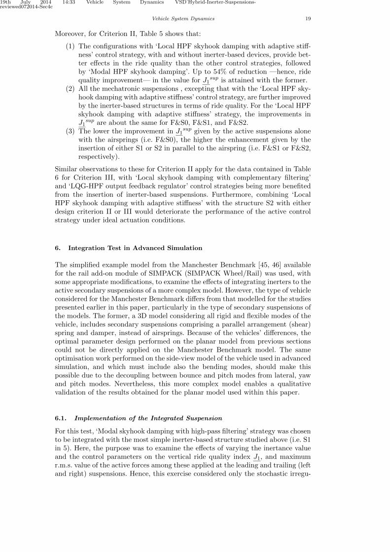
Similar observations to these for Criterion II apply for the data contained in Table6 for Criterion III, with ‘Local skyhook damping with complementary filtering’and ‘LQG-HPF output feedback regulator’ control strategies being more benefitedfrom the insertion of inerter-based suspensions. Furthermore, combining ‘LocalHPF skyhook damping with adaptive stiffness’ with the structure S2 with eitherdesign criterion II or III would deteriorate the performance of the active controlstrategy under ideal actuation conditions.
6. Integration Test in Advanced Simulation
The simplified example model from the Manchester Benchmark [45, 46] availablefor the rail add-on module of SIMPACK (SIMPACK Wheel/Rail) was used, withsome appropriate modifications, to examine the effects of integrating inerters to theactive secondary suspensions of a more complex model. However, the type of vehicleconsidered for the Manchester Benchmark differs from that modelled for the studiespresented earlier in this paper, particularly in the type of secondary suspensions ofthe models. The former, a 3D model considering all rigid and flexible modes of thevehicle, includes secondary suspensions comprising a parallel arrangement (shear)spring and damper, instead of airsprings. Because of the vehicles’ differences, theoptimal parameter design performed on the planar model from previous sectionscould not be directly applied on the Manchester Benchmark model. The sameoptimisation work performed on the side-view model of the vehicle used in advancedsimulation, and which must include also the bending modes, should make thispossible due to the decoupling between bounce and pitch modes from lateral, yawand pitch modes. Nevertheless, this more complex model enables a qualitativevalidation of the results obtained for the planar model used within this paper.
6.1. Implementation of the Integrated Suspension
For this test, ‘Modal skyhook damping with high-pass filtering’ strategy was chosento be integrated with the most simple inerter-based structure studied above (i.e. S1in 5). Here, the purpose was to examine the effects of varying the inertance valueand the control parameters on the vertical ride quality index J1, and maximumr.m.s. value of the active forces among these applied at the leading and trailing (leftand right) suspensions. Hence, this exercise considered only the stochastic irregu-

19th July 2014 14:33 Vehicle System Dynamics VSD˙Hybrid-Inerter-Suspensions-reviewed072014-Sec4c
20 Taylor & Francis and I.T. Consultant
larities of the track. The implementation of the inerter-based device was performedby using a control element, as its linear dynamic is approximated by a transfer func-tion characterising its mechanical complex admittance. For this, measurement ofthe relative velocity of the vertical motion of each secondary suspension, no fil-tering and ideal actuation were required. An alternative to this, would have beento use SIMPACK force elements, but a new element to model the inerter elementwould have been required. For implementation of active suspensions with ‘ModalHPF skyhook damping’ control, accelerometers for measuring pitching and boun-cing accelerations at the vehicle body centre of gravity were incorporated, as well asan actuator with perfect dynamic in parallel to each suspension. The accelerationmeasurements were integrated and filtered by second-order filters as described inSub-section 4.2.1, with corner frequencies of fcb = 0.225 [Hz] and fcρ = 0.179 [Hz]for the bounce and pitch measurements, respectively, which were the settings usedin the previous section for the same configuration
6.2. Simulation results and validation
For this qualitative validation, manual tuning for vertical ride quality improvementwas performed on the three design parameters considered:Kb andKρ for the controlstructure described by Equation 22, and b1 for the inerter-based structure S1 inFigure 5. With this manual procedure, no value for the damping coefficient Kb,for a fixed value of the corner frequency fcb, was found to benefit the ride quality.Thus, Kb was set to zero and Kρ and b1 were adjusted to the best possible valuesto obtain different sets of parameters, enabling the aimed comparisons.
Due to the difficulty of performing manual tuning, a very small but meaningfulset of parameters Kρ − b1 was obtained after a trial-error procedure. In the sameway, a good setting for the gain Kρ of the only active configuration was attained.Note that the baseline passive performance is different to that in the previoussection, but the emphasis here is upon the performance of improvement.
Table 8. Performance indices with different settings for the model with novel suspensions in SIM-
PACK
Configuration Setting J1sup [%g] Max. Force [kN]
Conventional 5.71 0Only active (F) 4.38 1.6(a) Only passive (S1) 4.79 0(b) Novel mechatronic (F&S0//S1) –Opt. setting 1 4.66 0.3(c) Novel mechatronic (F&S0//S1) –Opt. setting 2 4.20 1.4
Table 8 summarises the ride quality index J1sup and the maximum r.m.s. act-
ive force value for the corresponding time-domain responses. It shows that ther.m.s. value of the maximum stochastic active force required for achieving 23% ofride quality improvement with respect to the conventional vehicle is of is 1.6 [kN],without inerters (this value corresponds to the front-right suspension). Also, byusing linear fitting on data shown in Table 8, it is found that this maximum forcevalue can be reduced in at least 39% to achieve the same ride quality. Table 9 showsthat this is qualitatively similar to the results obtained from optimal settings of thesame control configuration for the planar model. The same correspondence betweenoutcomes from the two models is expected for the response to deterministic trackprofiles, as well as with other integrated suspension configurations. Further relev-ant tests were left for a more dedicated work on complex simulations in a futurestudy.

19th July 2014 14:33 Vehicle System Dynamics VSD˙Hybrid-Inerter-Suspensions-reviewed072014-Sec4c
Vehicle System Dynamics 21
Table 9. Result comparison for 23% ride quality achievement in the planar model and the SIM-
PACK model
Model: Max. Force in conventional configuration Max. Force Reduction
Planar Model 727[N] 46%SIMPACK Model 1600[N] 39%
7. Concluding Remarks
Results from this paper contribute to the design of railway vehicle novel mechat-ronic suspensions. Analyses extracted from Tables 4–6 clearly reveal the potentialof these inerter-based mechanical networks for enhancing the ride quality of a rail-way vehicle equipped with active suspensions, and for reducing the actuator size inthe achievement of certain levels of improvement. Moreover, the outcomes indicatethat the benefits for ride quality enhancement and active forces reduction providedby inerter-based suspensions do not depend strictly on the control strategy buton the degree of ride quality improvement with respect to the default passive con-figuration. This relates to the levels of relative effort demanded to the —ideal—actuators, that is, with respect to each control strategy active force index in con-ventional configurations. This remark is supported by the trade-off curves shownin Figures 8–11.
The overall achievements are summarised as follows:
• Integrating inerter-based devices to the design of novel mechatronic suspensionsystems for enhancing a bogied railway vehicle vertical performance, simplifiesthe design problem for low to intermediate vertical ride quality improvements(e.g. up to 30%), by enabling suspension deflection and active force reduction.
• For further achievements over 30% of improvement, i.e. with ‘too soft’ suspen-sions, introducing inerters does not result much beneficial to simplify the controldesign trade-offs.
• By integrating inerter-based suspensions with the active control strategy ‘localHPF skyhook damping with adaptive stiffness’, it could be obtained up to 50%in force reduction (w.r.t. 5.65 [kN]) required for the active control strategy im-plemented without inerters) to achieve 30% of ride quality enhancement.
• The suspensions’ maximum deflection remain inside the common bound of3.5 [cm] in the achievement of up to 54% of ride quality improvement for thestudied control strategies with and without inerter-based suspensions. Again,‘local HPF skyhook damping with adaptive stiffness’ showed the best results,followed by modal HPF skyhook damping with up to 41%–44% of improvementwithout and with inerters, respectively.
• The actuators’ maximum force remain inside the common bound of 10 [kN] inthe achievement of up to 54% of ride quality improvement for the studied con-trol strategies with and without inerter-based suspensions. For this, also ‘localskyhook damping with adaptive stiffness’ showed the best results, followed bymodal HPF skyhook damping with up to 43%–46% of improvement without andwith inerters, respectively.
• Optimisation results related to the inerter-based configuration S1 showed that aconventional mechanical inerter estimated friction (cb1 = 1000 [Nsm−1]) is lowerthan the optimal damping value required for a 30% of ride quality improvement,hence, a damper in series is required for this configuration (see Table 7).
• Even the level of simplification of a planar model such as the side-view modelwe used here, the qualitative results on the potential of the inerter for the designof mechatronic suspensions were replicated —even without optimisation— in amore complex 3D model of a similar vehicle.

19th July 2014 14:33 Vehicle System Dynamics VSD˙Hybrid-Inerter-Suspensions-reviewed072014-Sec4c
22 REFERENCES
The simplicity of the vertical ride quality problem, as compared to other morecomplex issues arising in the dynamics of a railway vehicle, enabled a better under-standing of the potential of inerter-based suspension configurations. Future workwill include practical aspects of passive inerters and actuators, as well as moreaccurate models of the vehicle to take account of engineering realities such as non-linearities, flexibilities, etc. Further research will consider more demanding railwaydynamic problems such as lateral stability and the inherent trade-off with therequirements of quasi-static curving as a more complex application of the novelmechatronic suspensions.
Acknowledgements
This work was supported by Universidad de Los Andes, Venezuela and via a de-partmental scholarship from the School of Electronics, Electrical and Systems En-gineering, Loughborough University, UK. We thank SIMPACK UK for the supportin providing a free limited license of SIMPACK Rail module. We are also thank-ful for the helpful discussions with Professor Malcolm Smith and Dr. Jason JiangZheng on the inerter applications and technology.
References
[1] R.M. Goodall and T.X. Mei, 2006, Active Suspensions. in Handbook of railway vehicle dynamics CRCPress, United States of America, p. 327.
[2] M.J. Smith, K.M. Grigoriadis, and R.E. Skelton, The Optimal Mix of Passive and Active Control inStructures, in Proceedings of the American Control Conference 1991, 1991, pp. 1459–1464.
[3] G. Corriga, S. Sanna, and G. Usai, An optimal tandem active-passive suspension system for roadvehicles with minimum power consumption, Industrial Electronics, IEEE Transactions on 38 (1991),pp. 210–216.
[4] A. Giua, C. Seatzu, and G. Usai, A mixed suspension system for a half-car vehicle model, Dyn.Control10 (2000), pp. 375–397.
[5] I. Pratt, Active suspension applied to railway trains, Loughborough University, Loughborough, UnitedKingdom, 1996.
[6] A. Orvnas, On Active Secondary Suspension in Rail Vehicles to Improve Ride comfort, KTH Engin-eering Sciences, Stockholm, Sweden, 2011.
[7] H. Md Yusof, Technologies and control for active railway suspension actuators, Loughborough Uni-versity, Loughborough, United Kingdom, 2013.
[8] F.C. Wang and H.A. Chan, Mechatronic suspension system and method for shock absorbing thereof;U.S. Patent US 2010/0148463 A1 (2010).
[9] ———, Mechatronic Suspension Design and its Applications to Vehicle Suspension Control, Pro-ceedings of the 47th IEEE Conference on Decision and Control (2008).
[10] F.C. Wang and H. Chanan , Network Optimization and Synthesis using a Combined Mechanical andElectrical System: Application to Vehicle Suspension Control, in Proceedings of the 19th InternationalSymposium on Mathematical Theory of Networks and Systems, Budapest, Hungary, 2010.
[11] F.C. Wang and H.A. Chan, Network Optimization and Synthesis using a Combined Mechanicaland Electrical System: Application to Vehicle Suspension, in Proceedings of the 19th InternationalSymposium on Mathematical Theory of Networks and Systems MTNS 2010, Budapest, Hungary,2010.
[12] M.C. Smith, Synthesis of mechanical networks: The inerter, IEEE Transactions on Automatic Control47 (2002), pp. 1648–1662.
[13] S. Evangelou, D.J.N. Limebeer, R.S. Sharp, and M.C. Smith, Mechanical steering compensators forhigh-performance motorcycles, Journal of Applied Mechanics- Transactions of the ASME 74 (2007),pp. 332–346.
[14] S. Evangelou, D.J.N. Limebeer, R.S. Sharp, and M.C. Smith, 2006, Vol. 329, An H-inf Loop-ShapingApproach to Steering Control for High-Performance Motorcycles. in Control of Uncertain Systems(LNCIS) Springer-Verlag, Germany, p. 257.
[15] M.C. Smith, Force-controlling mechanical device; U.S. Patent US 7316303 B2 (2008).[16] B. Gartner and M. Smith, Damping and inertial hydraulic device; PCT W0 2011/095787 A1 (2011).[17] F.C. Wang, M.S. Hsu, W.J. Su, and T.C. Lin, Screw type inerter mechanism; U.S. Patent US
2009/0108510 A1 (2009).[18] M.C. Smith, N.E. Houghton, P.J.G. Long, and R.A. Glover, Force-controlling hydraulic device; U.S.
Patent US 2012/0199428 A1 (2012).[19] R. Tuluie, Fluid Inerter; PCT WO 2011/089373 A1 (2011).[20] M.Z.Q. Chen, C. Papageorgiou, F. Scheibe, F.C. Wang, and M.C. Smith, The missing mechanical
circuit element, Circuits and Systems Magazine, IEEE 9; 9 (2009), pp. 10–26.

19th July 2014 14:33 Vehicle System Dynamics VSD˙Hybrid-Inerter-Suspensions-reviewed072014-Sec4c
REFERENCES 23
[21] J.Z. Jiang, A.Z. Matamoros-Sanchez, R.M. Goodall, and M.C. Smith, Passive suspensions incorpor-ating inerters for railway vehicles, Vehicle System Dynamics 50 (2012), pp. 263–276.
[22] F.C. Wang, The performance improvements of train suspension systems with inerters, Proceedingsof the 45th IEEE Conference on Decision and Control 1 (2006), pp. 1110–1115.
[23] F.C. Wang, M.K. Liao, B.H. Liao, W.J. Su, and H.A. Chan, The performance improvements oftrain suspension systems with mechanical networks employing inerters, Vehicle System Dynamics 47(2009), pp. 805–830.
[24] F.C. Wang and M.K. Liao, The lateral stability of train suspension systems employing inerters,Vehicle System Dynamics 48 (2009), pp. 619–643.
[25] J.Z. Jiang, A.Z. Matamoros-Sanchez, R.M. Goodall, and M. Smith, 2012, Performance Benefits inTwo-Axle Railway Vehicle Suspensions Employing Inerters. in Developments in Control Theory to-wards Glocal Control Institute of Engineering and Technology (IET).
[26] F.C. Wang, M.R. Hsieh, and H.J. Chen, A full-train with inerters: stability and performance, inProceedings of the 22nd International Symposium on Dynamics of Vehicles on Roads and Tracks,Manchester, UK, 2011.
[27] S. Bruni, R. Goodall, T.X. Mei, and H. Tsunashima, Control and monitoring for railway vehicledynamics, Vehicle System Dynamics 45 (2007), pp. 743–779.
[28] A.Z. Matamoros-Sanchez, The use of novel mechanical devices for enhancing the performance ofrailway vehicles, Loughborough University, Loughborough, United Kingdom, 2013.
[29] S. Bruni, J. Vinolas, M. Berg, O. Polach, and S. Stichel, Modelling of suspension components in arail vehicle dynamics context, Vehicle System Dynamics 49 (2011), p. 1021.
[30] H. Li, Non-linear control approaches for active railway suspensions; M.Phil thesis, LoughboroughUniversity, 1997.
[31] E. Foo and R. Goodall, Active suspension control strategies for flexible-bodied railway vehicles, inProceedings of Control ’98. UKACC International Conference on (Conf. Publ. No. 455), Vol. 2,1998, pp. 1300–1305.
[32] X. Zheng, Active vibration control of flexible bodied railway vehicles via smart structures, Loughbor-ough University, Loughborough, United Kingdom, 2011.
[33] H. Li and R.M. Goodall, Linear and non-linear skyhook damping control laws for active railwaysuspensions, Control Engineering Practice 7 (1999), pp. 843–850.
[34] A.Z. Matamoros-Sanchez and R.M. Goodall, The optimisation problem in the enhancement of railwayvehicles performance using novel suspension systems, in Proceedings of the XI International Congresson Numerical Methods in Engineering and Applied Sciences, Venezuela, 2012.
[35] International Organization for Standardization, ISO 2631-1; 1997.[36] V.K. Garg and R.V. Dukkipati Dynamics of Railway Vehicle Systems, Accademic Press, United
Kingdom, 1984.[37] CEN, European prestandard ENV 12299; 1999.[38] N.J. Mansfield, Literature Review on Low Frequency Vibration Comfort, , 2006 Asia Link Program.[39] R. Narayanamoorthy, V.H. Saran, V.K. Goel, S.P. Harsha, S. Khan, and M. Berg, Determination of
Activity Comfort in Swedish Passenger Trains, in Proceedings of the 8th World Congress on RailwayResearch, Seoul, Korea COEX, 2008.
[40] M.K. Bhiwapurkar, V.H. Saran, S.P. Harsha, V.K. Goel, and M. Berg, Effect of Magnitudes andDirections (Mono-Axis and Multi-Axis) of Whole Body-Vibration Exposures and Subjects Postureson the Sketching Performance, Proceedings of the Institution of Mechanical Engineers, Part F: Journalof Rail and Rapid Transit 225 (2011), pp. 71–83.
[41] D. Karnopp, 1973, Vol. 1, Active and passive isolation of random vibration. in Isolation of MechanicalVibration Impact and Noise ASME Monograph, American Society of Mechanical Engineers, NewYork, p. 64.
[42] MathWorks, Optimization Toolbox. Matlab R2012b., Matlab Users Guide (2012).[43] P. Dorato, C. Abdallah, and V. Cerone Linear-Quadratic Control: An Introduction, Prentice Hall,
USA, 1995.[44] G.F. Franklin, J.D. Powell, and A. Emami-Naeini Feedback Control of Dynamic Systems, 4th edition
Prentice Hall, Upper Saddle River, NJ, 2002.[45] S. Iwnicki, The Manchester Benchmarks for rail simulators - an introduction, Vehicle System Dy-
namics 29 (1998), pp. 717–722.[46] ———, Manchester Benchmarks for Rail Vehicle Simulation, Vehicle System Dynamics 30 (1998),
pp. 295–313.
Nomenclature
βv Vehicle body pitching mode [rad]βb1,2 Leading and trailing bogie pitching mode [rad]
S δzt (ωt) p.s.d. of the track elevation rate[(m/s) (rad/s)−1
]κ A design parameter in HPF skyhook damping with adaptive stiffness control
strategyA, Bu, Cm, Du, Cχ, Dχ, Ku, Ke, Q, R, V, W, η Scalar and matrix parameters
in the linear-quadratic output regulator designΩz Vertical roughness coefficient [m]

19th July 2014 14:33 Vehicle System Dynamics VSD˙Hybrid-Inerter-Suspensions-reviewed072014-Sec4c
24 REFERENCES
F&S0, F&S1, F&S2 Labels for hybrid suspensionsS0, S1, S2 Labels for passive suspensions, being S0 the conventional airspring and
S1–S2 inerter-based structuresσ Variance symbolx′(t), x′(t) State vector and estimated state vector in the linear-quadratic output
regulatorym(t) Measured output for the linear-quadratic output regulator
yzv Vector of vehicle r.m.s. accelerations[ms−2
]csky, Kl, Kb, Kρ Control gains in sky-hook damping configurationsfc Filtering corner frequency for the sky-hook damping configurations [Hz]Fa1,2 Front and rear airspring forces [N]Fc1,2 Front and rear suspension active forces [N]Fp1−4 Primary suspension forces connecting leading and trailing wheelsets to the
front and rear bogies [N]Fpn,1−2 Front and rear suspension passive network forces [N]Fu1,2 Front and rear mechatronic forces [N]fwz(t) Deterministic profile function [m]GHPF(s), GLPF(s) Transfer functions of high-pass and low-pass filters for sky-hook
damping configurationsJ1 Vector of ride quality penalisation indices [%g]Jsup1 Least ride quality penalisation index [%g]J2 Suspension deflection index vector [cm]J3 Active force index vector [N]JLQR Performance measure of the linear-quadratic output regulatorxiD1,2 (t) , xpf1,2 (t) , χ (t) , ζ(t), θ(t) Variables in the linear-quadratic output reg-
ulator designzv Vehicle body vertical bouncing mode [m]zb1,2 Leading and trailing bogie bouncing mode [m]zw1−4 Vertical track profile entering through the wheelsets of the leading and
trailing bogies [m]Ya(s) Airspring (secondary suspension) admittance function.Yp(s) Primary suspension admittance function.