
Novel Heat Exchanger Design With Rectangular Shell Geometry
7
NOVEL HEAT EXCHANGER DESIGN WITH RECTANGULAR SHELL GEOMETRY Vipul Patel* Department of Mechanical Engineering, Gujarat Power Engineering & Research Institute, Mehsana, Gujarat 382 710, India Rajesh Patel Vimal Savsani Department of Mechanical Engineering, Pandit Deendayal Petroleum University, Gandhinagar, Gujarat 382 007, India ABSTRACT Shell and Tube Heat Exchangers (STHE) are the most versatile type of heat exchangers used in industrial applications. The shape of Shell side of the traditional STHE’s is cylindrical for industrial applications. On one hand, STHE have some good features but on the other hand, it has some limitations due to the cylindrical geometry of the shell side. Some of these limitations are maximum two shell pass is possible as per TEMA layout, complete counter flow cannot be achieved, possibility of reverse heat transfer when number of tube passes are more, tubes are always laid parallel to shell and mounting over the entire length of shell is not possible when impingement plate provided etc. The objective of this study is to design a novel heat exchanger to overcome the limitations of traditional STHE. An experimental setup has been designed with rectangular shell side for STHE. The novel heat exchanger provides the flexibility to increase the number of shell pass and complete counter flow can be achieved due to rectangular geometry of shell side. For the same heat transfer rates, the proposed novel heat exchanger design provides better Effective Mean Temperature Difference (EMTD) and hence less surface area for heat transfer in comparison with traditional STHE. The experiments have been conducted on novel heat exchangers under different operation conditions of hot and cold fluids. The experiment results are compared with theoretical estimations of overall heat transfer coefficient and Log Mean Temperature Difference (LMTD) for traditional shell and tube heat exchangers for the same operation conditions. The results show that under the same operation conditions, the performance of novel heat exchanger is much better than traditional STHE. INTRODUCTION The need of the time is to design the heat exchangers which have high heat transfer rates with minimum possible surface area for heat transfer. Varieties of heat exchangers are used for industrial applications, such as shell-and-tube heat exchangers, plate-fin heat exchangers, fin and tube heat exchangers, etc. Among all, the shell-and-tube heat exchangers (STHE) are relatively simple to manufacture, used for both gaseous and liquid media, large temperature and pressure range etc., hence they are widely used in chemical industry, power plants, food industry, environment engineering, waste heat recovery, air-conditioning, refrigeration system etc. Shell and tube heat exchangers have some good features on one hand but on the other hand they have some limitations like their effectiveness and LMTD is less compare to plate heat exchangers, flow induce vibration on tube side [1], not well suited for temperature cross conditions, contains stagnant zones (dead zones) on the shell side which can lead to corrosion problems, large shell to bundle by pass for removable bundle type heat exchangers, more than two-shell pass is mechanically impractical [2], flow maldistribution (non- uniform distribution of mass flow rate on one or both fluid sides) [3]. Research efforts have been made to improve the heat transfer rate and to reduce the size of STHE by conducting experiments, CFD simulations of heat transfer and fluid flow transport and use of optimization techniques. Experimental research work involves modifications on the shell side and tube side components arrangement of SHTE. The modifications on the shell side accommodate use of overlapped helical baffle [4], continuous helical baffle [5], inclined baffle [6] etc. to enhance turbulence and to reduce the pressure drop; use of the sealer to reduce the bypass losses between shell and baffles [7]. The tube side experimental research work involve use of different diameter tube [8], helical tube to reduce the fouling [9], * Current Address of Vipul Patel: Pandit Deendayal Petroleum University, Gandhinagar 382 007, India 1 Copyright © 2014 by ASME Proceedings of the ASME 2014 International Mechanical Engineering Congress and Exposition IMECE2014 November 14-20, 2014, Montreal, Quebec, Canada IMECE2014-36834
Transcript of Novel Heat Exchanger Design With Rectangular Shell Geometry

NOVEL HEAT EXCHANGER DESIGN WITH RECTANGULAR SHELL GEOMETRY
Vipul Patel*
Department of Mechanical Engineering, Gujarat Power Engineering & Research Institute,
Mehsana, Gujarat 382 710, India
Rajesh Patel Vimal Savsani
Department of Mechanical Engineering, Pandit Deendayal Petroleum University,
Gandhinagar, Gujarat 382 007, India
ABSTRACT Shell and Tube Heat Exchangers (STHE) are the most
versatile type of heat exchangers used in industrial applications.
The shape of Shell side of the traditional STHE’s is cylindrical
for industrial applications. On one hand, STHE have some good
features but on the other hand, it has some limitations due to the
cylindrical geometry of the shell side. Some of these limitations
are maximum two shell pass is possible as per TEMA layout,
complete counter flow cannot be achieved, possibility of
reverse heat transfer when number of tube passes are more,
tubes are always laid parallel to shell and mounting over the
entire length of shell is not possible when impingement plate
provided etc. The objective of this study is to design a novel
heat exchanger to overcome the limitations of traditional
STHE. An experimental setup has been designed with
rectangular shell side for STHE. The novel heat exchanger
provides the flexibility to increase the number of shell pass and
complete counter flow can be achieved due to rectangular
geometry of shell side. For the same heat transfer rates, the
proposed novel heat exchanger design provides better Effective
Mean Temperature Difference (EMTD) and hence less surface
area for heat transfer in comparison with traditional STHE. The
experiments have been conducted on novel heat exchangers
under different operation conditions of hot and cold fluids. The
experiment results are compared with theoretical estimations of
overall heat transfer coefficient and Log Mean Temperature
Difference (LMTD) for traditional shell and tube heat
exchangers for the same operation conditions. The results show
that under the same operation conditions, the performance of
novel heat exchanger is much better than traditional STHE.
INTRODUCTION
The need of the time is to design the heat exchangers
which have high heat transfer rates with minimum possible
surface area for heat transfer. Varieties of heat exchangers are
used for industrial applications, such as shell-and-tube heat
exchangers, plate-fin heat exchangers, fin and tube heat
exchangers, etc. Among all, the shell-and-tube heat exchangers
(STHE) are relatively simple to manufacture, used for both
gaseous and liquid media, large temperature and pressure range
etc., hence they are widely used in chemical industry, power
plants, food industry, environment engineering, waste heat
recovery, air-conditioning, refrigeration system etc.
Shell and tube heat exchangers have some good
features on one hand but on the other hand they have some
limitations like their effectiveness and LMTD is less compare
to plate heat exchangers, flow induce vibration on tube side [1],
not well suited for temperature cross conditions, contains
stagnant zones (dead zones) on the shell side which can lead to
corrosion problems, large shell to bundle by pass for removable
bundle type heat exchangers, more than two-shell pass is
mechanically impractical [2], flow maldistribution (non-
uniform distribution of mass flow rate on one or both fluid
sides) [3].
Research efforts have been made to improve the heat
transfer rate and to reduce the size of STHE by conducting
experiments, CFD simulations of heat transfer and fluid flow
transport and use of optimization techniques. Experimental
research work involves modifications on the shell side and tube
side components arrangement of SHTE. The modifications on
the shell side accommodate use of overlapped helical baffle [4],
continuous helical baffle [5], inclined baffle [6] etc. to enhance
turbulence and to reduce the pressure drop; use of the sealer to
reduce the bypass losses between shell and baffles [7]. The tube
side experimental research work involve use of different
diameter tube [8], helical tube to reduce the fouling [9],
* Current Address of Vipul Patel: Pandit Deendayal Petroleum
University, Gandhinagar 382 007, India
1 Copyright © 2014 by ASME
Proceedings of the ASME 2014 International Mechanical Engineering Congress and Exposition IMECE2014
November 14-20, 2014, Montreal, Quebec, Canada
IMECE2014-36834

corrugated or micro-fins [10], wire coil and wire mesh [11],
spiral tube [12] to enhance the turbulence and to improve the
heat transfer coefficient. Optimization is another way to
increase the performance and to reduce the size of the STHE.
Various optimization techniques have been applied to optimize
the capital cost and operating cost of STHE such as:
Irreversibility minimization method [13], Global Sensitivity
Analysis (GSE) [14], Harmony Search Algorithm (HAS) [15],
Biogeography-Based (BBO) algorithm [16], Constructal
Theory Method [17], Entransy Dissipation-based Thermal
Resistance Method [18], Heat Exchanger Networks (HENs)
design [19], Particle Swarm Optimization [20] etc. CFD is very
important tool to foresee the performance of the system before
adapting the system and also provides flexibility to change
design parameters without the expense of hardware changes. It
therefore costs less than laboratory or field experiments,
allowing engineers to try more alternative designs than would
be feasible otherwise. It also reduces design cycle time and cost
by optimizing through computer predictions and provides
higher level of confidence in prototype or field installed
performance. CFD has been used to investigate the
performance of the heat exchanger for many applications: CFD
analysis of the STHE with use of triangular fin [22, 23], CDF
for finding optimum parameter [24], performance analysis of
the Un-baffle heat exchanger [25], effects of baffle inclination
on fluid Flow [26] etc.
Literature review shows that lots of the research work
has been done on the STHE to improve the performance and
optimization of the total cost. Most of the documented research
work is done on shell side with baffle and tube side with
different geometry of tube. However due to the cylindrical
geometry of the shell side, STHE have many limitations and
disadvantages other than those listed above, which are:
1. In the shell and tube heat more than two shell pass is not
possible due to geometry limitation; hence complete
counter flow is not possible.
2. Achieving outlet temperature of cold fluid higher than
outlet temperature of hot fluid is difficult with one shell
and tube heat exchanger. These require series of heat
exchanger.
3. Stream C, E, & F loss.
4. On Shell side if impingement plate is provide then tubes
cannot be place in that portion over the entire length of the
STHE.
5. Contains stagnant zones (dead zones) on the shell side
which can lead to corrosion problems.
Majority of above problems and disadvantages of
traditional STHE can be overcome by changing the cylindrical
geometry of the shell side by square/rectangular geometry. Our
literature survey has revealed that there is no documented
research work on the square/rectangle geometry of shell side of
STHE.
The objective of this study is to design a Novel Heat
Exchanger (NHE) which has square/rectangle geometry of shell
side while tubes are of cylindrical in shape. The experimental
setup has been designed to predict the performance of NHE.
The experimental results on the performance of NHE are
compared with theoretical estimations for STHE for the same
input conditions and equivalent heat transfer surface area. Our
study shows that NHE provides much improved heat transfer
rates than the traditional STHE.
NOVEL HEAT EXCHANGER DESIGN The motive behind this study was the tube pass
arrangement for traditional STHE and the proposed NHE as
shown in Fig. 1. The comparison shows that it is possible to
have the number of the shell pass equal to the number of tube
pass for NHE, which is not the case for STHE. Hence the flow
of the hot and the cold fluid flow is always in counter flow
direction and temperature correction factor is greater than that
of the STHE. As per TEMA standard maximum two shell pass
is possible for traditional STHE due to its shell side geometry
which is cylindrical in shape. However with NHE, as many
number of shell pass required can be arranged with proposed
design as shown in Fig. 1.
Figure 1 Tube pass arrangement for NHE and STHE
Figure 2 shows the proposed Novel Heat Exchanger
(NHE) design with rectangular geometry of shell side while the
figure 3 shows the tube arrangement, baffles position and the
fluid flow arrangement.
Figure 2 NHE design model
2 Copyright © 2014 by ASME

Figure 3 Line diagram for NHE configuration
The shell side fluid flows from top to bottom of NHE
with constant flow area for each pass. As shown in figure 2 &
3, each tube pass form a rectangular section and between tube
pass horizontal baffle is provided on shell side. The number of
horizontal baffles depends on the number of shell pass. Vertical
baffle is provided in the longitudinal direction of the tube to
support the tubes and to create turbulence on shell side. The
number of vertical baffles and tube number of pass depends on
type of baffle and maximum pressure drop available on the
shell side. However the number of tube pass depends on the
maximum pressure drop on tube side. Shell side fluid and tube
side fluids are separated by tube sheet.
EXPERIMENT SETUP
Figure 4 Experiment setup for NHE
Fig 4 shows the line diagram of the experimental
setup. Experimental set up consists of the two rotameters, four
pressure gauges, four thermocouples, two motors with pumps
fluid supply pipes, data acquisition system and two fluid
storage tanks. Rota meters are connected between fluid storage
tank and NHE to measure flow rate of fluids. Pressure gauges
are attached at inlet and outlet of hot and cold fluid side to
measure the pressure. Thermocouples are attached at inlet and
outlet of hot and cold fluid to measure the temperatures.
Thermocouples are connected with data acquisition system for
recording the temperature at different time intervals.
Hot water is supplied to the shell-side and cold water
supplied to the tube-side by pumps. Hot water is supplied from
the boiler. The experiments are performed at different flow rate
and different temperature of hot fluid. NHE experimental
performance data are compared with shell and tube heat
exchanger data for same flow rate and inlet-outlet temperatures
and heat transfer area.
HEAT TRANSFER MODEL FOR HEAT EXCHANGER In order to compare the performance of NHE with
traditional STHE, in this study we have selected single-shell
pass and four-tube pass STHE for comparison. The
experimental data of NHE such as inlet and outlet temperatures
of hot and cold fluids, flow rates of hot and cold fluid were
taken as input data for the heat transfer model of single-shell
pass and four-tube pass STHE. The estimated heat transfer area
from heat transfer model for single-shell pass and four-tube
pass STHE were compared with the NHE heat transfer area.
The heat transfer model used for the performance
analysis of single-shell pass and four-tube pass SHTE is taken
from the Sadik Kakac [20];
Flow Area
The flow area of shell side for both NHE and STHE is
different due to different geometrical shape, however the tube
side flow are is same for both NHE and STHE.
The shell side flow area for the single-shell pass and
four-tube pass heat exchanger can be written as;
( ). .T s s
T
P d B Da
P
−= (1)
Heat transfer area The heat transfer area of the shell and tube heat
exchanger can be estimated from;
. . .T
A d l Nπ= (2)
Theoretical over all Heat Transfer Coefficient (Uth) Uth is the theoretical overall heat transfer coefficient
for the shell and tube heat exchanger which depends on the
geometry of the heat exchanger and the themo-physical
properties of the flowing fluids.
.ln1 1
.
oo
io
th o i i
rr
rr
U h r h k
= + + (3)
Where, ho is shell side heat transfer coefficient, hi is
tube side heat transfer coefficient, ro and ri are outer and inner
radius of tube respectively.
3 Copyright © 2014 by ASME

Theoretical overall heat transfer coefficient Uth depends on the
tube and shell side heat transfer coefficient. Tube side and shell
side heat transfer coefficients were found by applying Bell
Delaware method for STHE. Bell-Delaware’s method was
issued after 16 years of experimentation on shell side flow in
laboratory. Nowadays, this method is commonly used in
manual calculations [26]. This method is simple and reliable
enough to be used in engineering applications with reasonable
accuracy. Since then many software have been developed based
on Bell Delaware method [27]. The tube side and shell side
heat transfer coefficients can be represented using Bell-
Delaware method [20, 21] which are represented in Table 1.
Table1: Shell and tube side heat transfer coefficient
Tube side
heat
transfer
Coefficient
(hi)
�� ��� � ��2 � �� � �
1.07 � 12.7 � ��2�.� � �� �� � 1��
For 0.5 � � � 2000, 10� � �� � 5 � 10 , � � !1.58 � ln �� � 3.28�&�
�� ��� � ��2 � !�� � 1000� � �
1 � 12.7 � ��2�.� � �� �� � 1��
For 0.5 � � � 2000, 2300 � �� � 10�, � � !1.58 � ln �� � 3.28�&�
Shell side
heat
transfer
Coefficient
(ho)
� � 0.36 � �� � ���.�� � �� �� � ( µ
µ)*�.+�
For 2000 � �� � 100000
As per Kern method
�, � - � ./ � 01 � �234 � �� �� � ( µ
µ)*�.+�
Where j� 0.37 � ��&�.�5�, ./ � 6,���67�,8 �467,�
As per Bell-Delaware method
Heat Duty (Q) For any heat exchanger we may write the heat balance
in the form of;
( ) ( ). . . .h ph hi ho c pc co ciQ m C T T m C T T= − = −& & (4)
Above equation is a general form of energy exchange
between hot and cold fluid in an ideal heat exchanger (i.e. heat
lost by one fluid is equal to heat gained by the second fluid
under steady state condition).
LMTD LMTD can be estimated with inlet and outlet
temperature of the hot fluid and cold fluid of heat exchangers
by;
1 2
1
2
ln
LMTDθ θ
θ
θ
−=
(5)
Actual Over all Heat Transfer Coefficient (Uact)
Overall heat transfer coefficient is main parameter to
compare the performance of any heat exchanger. Uact is
experimental estimation of the overall heat transfer coefficient
for known heat duty of the heat exchanger and LMTD.
. .act
QU
A LMTD F= (6)
Where, F = Temperature correction factor which
indicates the performance level of a given arrangement for
given terminal fluid temperatures. It depends on the number of
tube pass, number of shell pass, type of shell, type of flow
(Cross flow, counter flow or Parallel flow), etc. The correction
factor F is always less than unity.
SOLUTION PROCEDURE In order to compare performance of the proposed NHE
with the traditional for single-shell pass and four-tube pass
STHE, the experimental results of NHE are compared with the
theoretical estimations of single-shell pass and four-tube pass
STHE.
For the theoretical estimation of performance of
STHE, we have used the heat transfer model proposed in the
previous section. In this study we have used the same
geometrical data of the tube side (number of tube, tube OD,
pitch, tube length, etc.) and the experimental data of NHE
exchanger i.e. input and output temperatures and flow rates of
hot and cold fluids provided in Table 2 were used as input
parameters to predict the required heat transfer area for STHE.
The estimated heat transfer area of STHE was then compared
with the actual surface area NHE for the different flow rates of
hot and cold fluid.
RESULTS AND DISCUSSIONS
The experiments are performed with NHE for different
flow rates of hot and cold fluids which are listed in the Table 2.
Table 2 Experiment data of NHE
Sr. No. 1 2 3
Parameter Shell
Side
Tube
Side
Shell
Side
Tube
Side
Shell
Side
Tube
Side
m(kg/s) 1.274 1.440 1.161 1.400 1.161 1.600
Tin (°C) 84.1 23.3 78.5 25 78.5 25
Tout (°C) 51.61 52.1 49 49.5 46.85 48
4 Copyright © 2014 by ASME
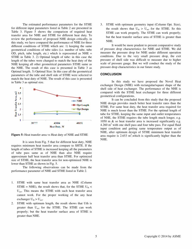
The estimated performance parameters for the STHE
for different input parameters listed in Table 2 are presented in
Table 3. Figure 5 shows the comparison of required heat
transfer area for NHE and STHE for different heat duty. To
review the performance of proposed NHE design critically, in
this study, we have compared the performance of NHE for three
different conditions of STHE which are: 1) keeping the same
geometrical conditions of tube sides (i.e. number of tube, tube
OD, pitch, tube length, etc.) which is represented as NHE =
STHE in Table 3. 2) Optimal length of tube: in this case the
length of the tubes were changed to match the heat duty of the
NHE keeping all other geometrical parameters STHE same as
the NHE. The result of this case is presented in Table 3 as
Optimal length. 3) Optimal Size: In this case all the geometrical
parameters of the tube and shell side of STHE were selected to
match the heat duty of NHE. The result of this case is presented
in Table 3 as optimal size.
Figure 5: Heat transfer area vs Heat duty of NHE and STHE
It is seen from Fig. 5 that for different heat duty, NHE
requires minimum heat transfer area compare to SHTE. If the
length of tubes of STHE is increased keeping all the parameters
of tube pass same as of NHE than also NHE require
approximate half heat transfer area than STHE. For optimized
size of STHE, the heat transfer area for non-optimized NHE is
lower than STHE as shown in Fig. 5.
The following observations can be made from the
performance parameter of NHE and STHE listed in Table 2.
1. STHE with same heat transfer area as NHE (Column
STHE = NHE), the result shows that, for the STHE Uth <
Uact. This means the STHE with such heat transfer area
cannot work. For the proper working of the any heat
exchanger Uth > Uact.
2. STHE with optimum length, the result shows that Uth is
greater than Uact for the STHE. The STHE can work
properly; but the heat transfer surface area of STHE is
greater than NHE.
3. STHE with optimum geometry input (Column Opt. Size),
the result shows that Uth > Uact for the STHE. So this
STHE can work properly. The STHE can work properly;
but the heat transfer surface area of STHE is greater than
NHE.
It would be more prudent to present comparative study
of pressure drop characteristics for NHE and STHE. We did
measure the pressure drop for NHE under different operation
conditions. Due to the very small pressure drop, the exit
pressure of shell side was difficult to measure due to higher
scale of pressure gauge. But we will conduct the study of the
pressure drop characteristics in our future study.
CONCLUSION
In this study we have proposed the Novel Heat
exchanger Design (NHE) with rectangular/square shape of the
shell side of heat exchanger. The performance of the NHE is
compared with the STHE heat exchanger for three different
geometrical configurations.
It can be concluded from this study that the proposed
NHE design provides much better heat transfer rates than the
STHE. For same heat duty, the heat transfer area required for
NHE is much lesser than the STHE. For the optimal length of
tube for STHE, keeping the same input and outlet temperatures
of NHE, the STHE requires the tube length much longer, e.g.
1050 m & so heat transfer area is increased significantly e.g.
4.260 m2 with one shell pass and four tube pass. For equal fluid
input condition and getting same temperature output as of
NHE, after optimum design of STHE minimum heat transfer
area require is 2.653 m2,which is significantly higher than the
NHE.
5 Copyright © 2014 by ASME

Table 3 Performance Parameter Comparison
NOMENCLATURE
A Heat transfer area, m2
Bs Baffle spacing for STHE, m
B NHE width, m
C Specific heat of kJ/kg-K F Temperature correction factor
D Equivalent diameter, m
Jc Overall correction factor
k Thermal conductivity, W/m-C
L Tube length, m
NT Number of tube
n Number of tube pass
PT Tube pitch, m
Q Heat duty, W
Re Reynolds Number
µ Viscosity, cP
µw Viscosity at wall temperature, cP
U Overall teat transfer coefficient, W/ m2-C
LMTD Log Mean Temperature Difference, C
H Heat Transfer Coefficient, W/ m2-C
d Tube diameter, m
N Number of Tube Pass
G Mass velocity, kg/s-m2
V Volume flow Rate, m3/s
v Velocity, m/s
Pr Prandtl number
Nu Nusselt number
C Tube clearance, m
ρ Density, kg/m3
Nb Number of baffle
R Fouling resistance, m2-C/W
SUBSCRIPT
w Wall
in Inlet
out Outlet
th Theoretical
act Actual/Experimental
p Pressure
i Inside
o Outside
ft Tube side
fs Shell Side
REFERENCES
1. Ramesh, K. and Shah, D., 2003, Fundamentals of Heat
Exchanger Design, Joln Wiley & Sons.
2. Donald, Q. and Kern, 2011, Process Heat Transfer, “Tata
McGraw Hill Education.
3. Sudhakara Rao, K., 2007, “Analysis Of Flow
Maldistribution In Tubular Heat Exchangers By Fluent”,
Thesis NIT Rourkela.
4. Zhang, J. F., Binli,W.J.,Yong, G., Ya, L., ,Wen Q., 2009,
"Experimental Performance Comparison of Shell-Side
Heat Transfer for Shell-and-Tube Heat Exchangers with
Middle-Overlapped Helical Baffles and Segmental
Baffles"Chemical Engineering science, 64 (8), pp. 1643-
1653.
5. Shiv Kumar, R., Ajeet, B., 2013, “Thermal analysis of
Helical Baffle in Heat Exchanger" International Journal of
Science and Research, 2(7), pp. 251-254.
6. Rajagapal, T., Karuppa, R., and Srikanth, G., 2012, “Shell
Side Numerical Analysis of A Shell and Tube Heat
Exchanger Considering The Effects of Baffle Inclination
Angle on Fluid Flow" International Journal of Heat and
Mass Transfer, 16 (4), pp. 1165–1174.
7. Simin, W., Jian, W., Yanzhong, L., 2009 "An
Experimental Investigation of Heat Transfer Enhancement
for A Shell-and-Tube Heat Exchanger" Applied Thermal
Engineering, 29 (11-12), pp. 2433–2438.
8. Sofia, G., Demetri, G., 2013, “Numerical Evaluation of A
Heat Exchanger With Inline Tubes Of Different Size for
Reduced Fouling Rates" International Journal of Heat And
Mass Transfer, 55 (19-20), pp. 5185–5195.
Parameter
1 2 3
NHE
STHE
NHE
STHE
NHE
STHE
STHE
=
NHE
Opt.
Length
Opt.
Size
STHE
=
NHE
Opt.
Length
Opt.
Size
STHE
=
NHE
Opt.
Length Opt. Size
Uact (W/m2-°°°°C) 1120 1390 712 1234 1056 1214 543 1162 1154 1363 725 1232
Uth (W/m2-°°°°C) NA 778 713 1310 NA 614 544 1239 NA 646 741 1077
A (m2) 1.588 1.588 3.078 1.721 1.588 1.588 3.880 1.730 1.588 1.588 3.289 1.838
Q 48204 48151 48151 48151 39860 39777 39777 39777 42765 42684 42684 42684
n 4 4 4 6 4 4 4 6 4 4 4 6
L 396 396 770 985 396 396 960 990 396 396 820 1050
Nt 112 112 112 48 112 112 112 48 112 112 112 48
6 Copyright © 2014 by ASME

9. Srbislav, B., Branislav, M., Marko, S., Nikola, J., 2013,
“Analysis of Fouling Factor in District Heating Heat
Exchangers With Parallel Helical Tube Coils" International
Journal Of Heat and Mass Transfer, 57 (1), pp. 9-15.
10. Hosseini, R., Hosseini-Ghaffar, A., Soltani, M., 2007,
“Experimental Determination of Shell Side Heat Transfer
Coefficient and Pressure Drop for An Oil Cooler Shell-
And-Tube Heat Exchanger With Three Different Tube
Bundles" Applied Thermal Engineering, 27 (5-6), pp.
1001–1008.
11. Pahlavanzadeh, H., Jafari Nasr, M. R., Mozaffari, S.H.,
2007, "Experimental Study of Thermo-Hydraulic And
Fouling Performance of Enhanced Heat Exchangers"
International Communications In Heat And Mass Transfer,
34 (7), pp. 907–916.
12. Jay, J., Bhavsar, V. K., Matawala, S., 2013, “Design and
Experimental analysis of Spiral Tube Heat Exchanger"
International Journal of Mechanical and Production
Engineering, 1(1), pp. 37–42.
13. Abbas Alwi, S. A., 2012, “Counter Flow Heat Exchangers'
Irreversibility Minimization" Natural and Applied
Sciences, pp. 57-69.
14. Fesanghary, M., Damangir, E., Soleimani, I., 2009,
“Design Optimization of Shell and Tube Heat Exchangers
Using Global Sensitivity Analysis and Harmony Search
Algorithm" Applied Thermal Engineering, 29 (5-6), pp.
1026–1031.
15. Amin, H., Ali, N., 2013, “Design and Economic
Optimization of Shell-and-Tube Heat Exchangers Using
Biogeography-Based (Bbo) Algorithm" Applied Thermal
Engineering, 51(1-2), pp. 1263-1272.
16. Abazar, V. A., Majid A., 2011 “Economic Optimization of
Shell and Tube Heat Exchanger Based on Constructal
Theory" Energy, 36 (2), pp. 1087-1096.
17. Qun, C., 3013, “Entransy Dissipation-Based Thermal
Resistance Method for Heat Exchanger Performance
Design and Optimization" International Journal of Heat
and Mass Transfer, 60, pp. 156–162.
18. Patel, V.K., Rao, R.V., 2010, “Design optimization of
Shell-and-Tube Heat Exchanger Using Particle Swarm
optimization Technique" Applied Thermal Engineering, 30
(11-12), pp. 1417-1425.
19. Ya, W., David, R., 2003, “Environmental and Economic
Assessments of Heat Exchanger Networks for Optimum
Minimum Approach Temperature" Computer and
Chemical Engineering, 27 (11), pp. 1577-1590.
20. Sadik K., “Heat Exchangers” Third Edition. 2012.
21. TEMA, Standards of Tubular Exchanger Manufacturers
Association, ninth edition. New York (2007).
22. Swapnaneel, S., and Das, D.H.,2012, “CFD Analysis of
Shell and Tube Heat Exchanger using triangular fins for
waste heat recovery processes" An International Journal
(ESTIJ), 2(6), pp. 2250-3498.
23. Khairun, H. O., “CFD Simulation Of Heat Transfer In
Shell And Tube Heat Exchanger" Thesis Universiti
Malaysia Pahang April 2009.
24. Usman Ur Rehman “Heat Transfer Optimization Of Shell-
And-Tube Heat Exchanger Through CFD Studies”
Master’s Thesis 2011.
25. Abdur, R,, Saad, S.M., 2012, “Shell Side CFD Analysis Of
A Small Shell-And-Tube Heat Exchanger Considering The
Effects Of Baffle Inclination On Fluid Flow” Proceedings
Of The National Conference On Trends And Advances In
Mechanical Engineering, Ymca University Of Science &
Technology, Faridabad, Haryana, India.
26. Bell, K. J., “Final Report of the Cooperative Research
Program on Shell and Tube Heat Exchangers” University
of Delaware Eng. Exp. Sta. Bull. 5, 1963.
27. Leong, K. C., Toh, K. C., and Leong, Y. C., “Shell and
Tube Heat Exchanger Design Software for Educational
applications” International Journal of Engineering
Education, 14, 3: 217-224, 1998.
7 Copyright © 2014 by ASME