Preliminär r ekonstruktionsplan Northland Resources AB Northland Sweden AB
COVERSHEET Subject Northland Shipyard & Floating Drydock Project Development Phase - Initial Report: October
2019 Portfolio of Provincial Development Unit Documentation Due to the public interest in Northport’s Study to Establish a Ship Repair Facility in Northland, and following consultation with the applicant, the Provincial Development Unit (PDU) has decided to proactively release some material which relates to information already available in the public sphere.
The application made by Northport to the Provincial Growth Fund (PGF) was approved by decision makers.
List of documents that have been proactively released
Title Summary Applicable Pages
Northland Shipyard & Floating Dry Dock Project Development Phase – Initial Report: October 2019
Report from funding applicant updating the Provincial Development Unit (PDU) on the findings of the study.
2 - 11
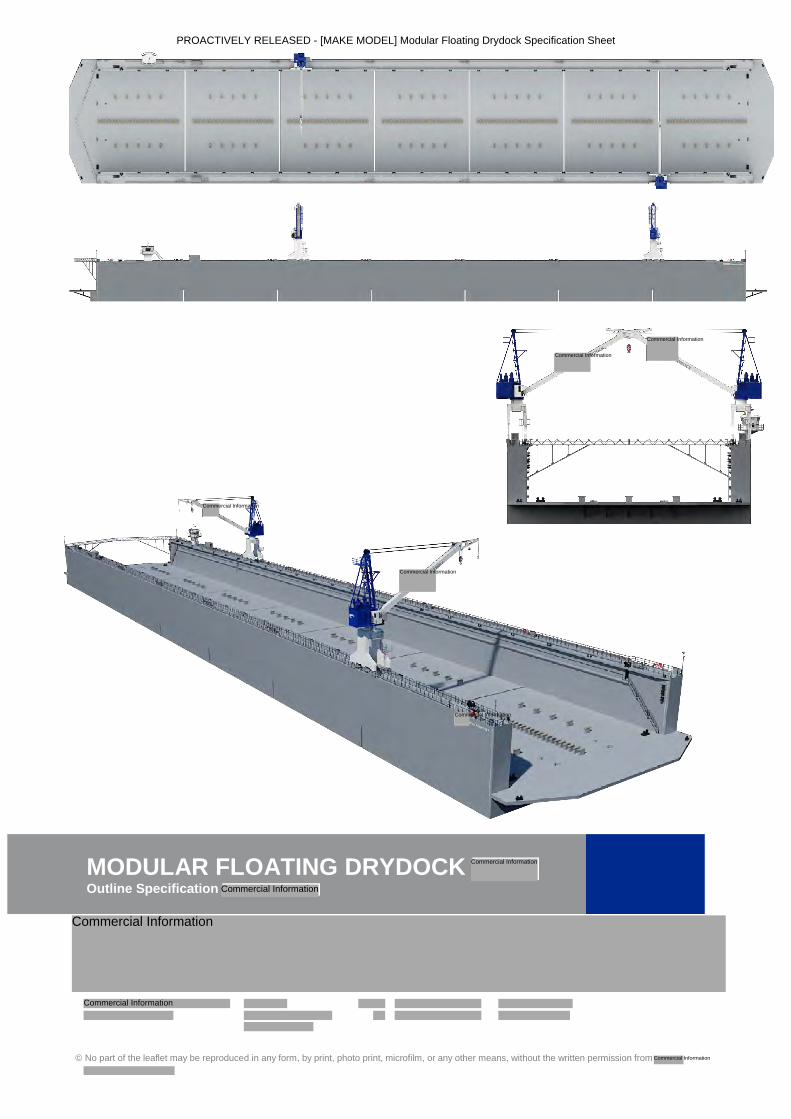
[MAKE MODEL] Floating Dry Dock Specification Sheet
Document containing specifications and dimensions of the proposed dry dock.
12 - 13
[MAKE MODEL] Floating Dry Dock Profile A series of visual designs depicting the profile of the proposed dry dock.
14
[COMPANY] Northport Ship Maintenance Facility: Concept Design & Construction Estimate
Report from a third-party contractor outlining the concept designs and construction estimate for the proposed dry dock.
15 - 57
Initia: Preliminary Geotechnical Report Preliminary report from Initia outlining the process and results of extensive geotechnical testing.
58 - 71
Be-Software: Phase 1 Ship Simulation Dry-Docking Report
Preliminary report from the funding applicant and Be-Software outlining the process and results of a simulation study.
72 - 84
Consenting Process Report Document outlining the consenting process for the Northland Shipyard and Floating Dry Dock Project.
85 - 87
Information redacted Any information redacted in this document is redacted in accordance with MBIE’s parameters for Proactive Release and is labelled with the reason for redaction. This may include information that would be redacted if this information was requested under Official Information Act 1982. Where this is the case, the reasons for withholding information are listed below. Where information has been withheld, no public interest has been identified that would outweigh the reasons for withholding it. Some information has been withheld to protect the confidentiality of advice tendered by ministers and officials, to protect the commercial position of the person who supplied the information, and to maintain the effective conduct of public affairs through the free and frank expression of opinions. © Crown Copyright, Creative Commons Attribution 4.0 International (CC BY 4.0)
Northland Shipyard & Floating Drydock Project
Development Phase
Initial Report : October 2019
PROACTIVELY RELEASED - Northland Shipyard and Floating Drydock Project - Initial Report October 2019
Northland Shipyard & Floating Drydock Project
Development Phase – Initial Report
October 2019
Executive Summary:
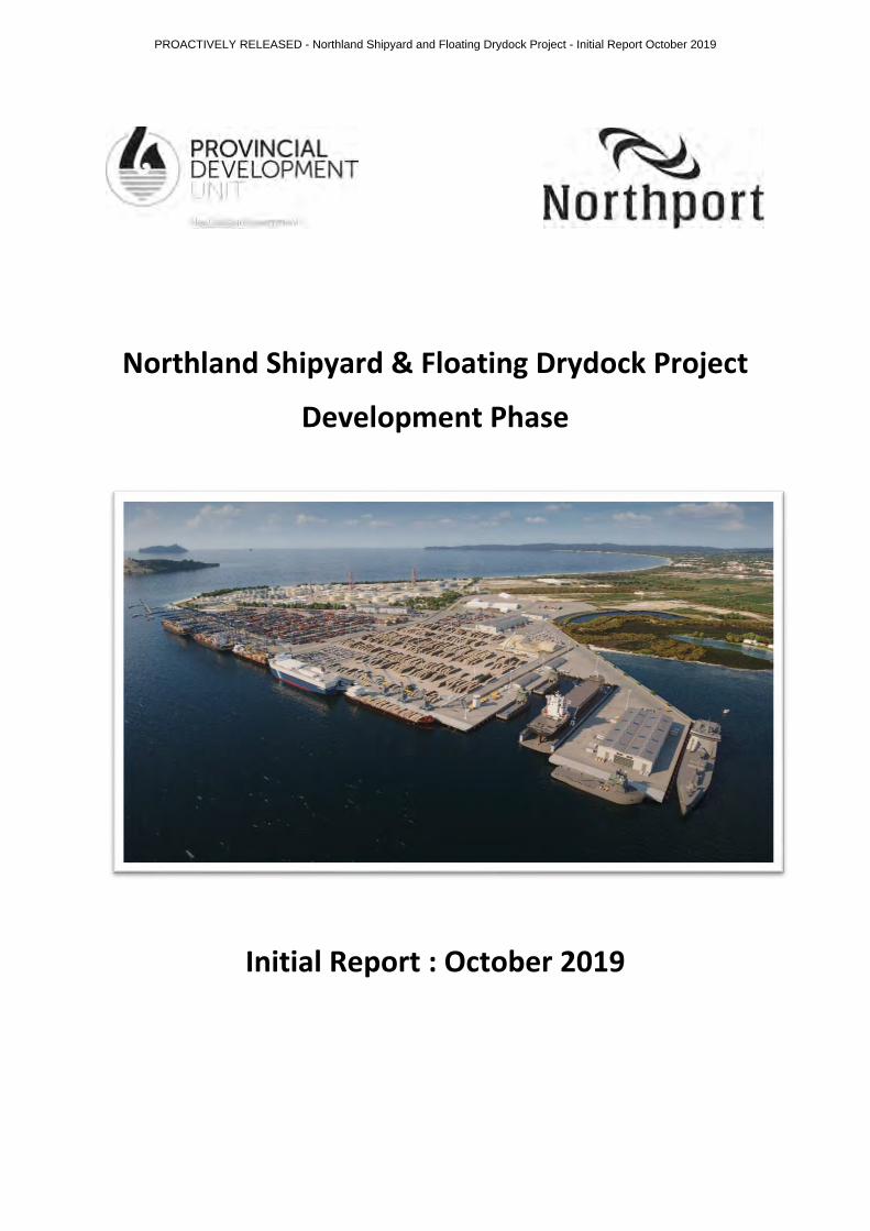
Phase 1 of the Development Funding has now been completed, the proposed shipyard and
floating drydock stakeholders have been consulted and a conceptual design for the shipyard
facility with the capability to accommodate a floating drydock (or a floating drydock
of similar design) has been undertaken, the construction methodology investigated, and a cost
estimate produced.
Ship-simulation for docking and undocking of various ship configurations that meet the
stakeholder requirements has been undertaken to ensure the safe and efficient operation of a
floating drydock in this location. All manoeuvres were carried out as dead-ship and used the
current marine plant and assumed suitable drydock mooring equipment. It should be
noted that due to the strong tidal flows experienced in the Whangarei Harbour at Marsden Point,
and potential for strong winds, there are some restrictions for docking/undocking operations;
further modelling will be undertaken once the final floating drydock model/design and shipyard
configuration is confirmed.
Phase 2 of the Development Funding provides for completion of the various studies and
consultation required to produce and submit an AEE (Assessment of Environmental Effects) for
resource consent application; proposed lodgement .
The estimated total cost of the proposed shipyard construction project, including provision for
identified opportunities/risk and the consenting process is circa NZ$
While no provision has been made for the costs of on-site buildings an estimate of NZ$ should
be considered.
has provided a cost estimate for the floating drydock and, depending on
final configuration and actual delivery, is circa NZ (this is based on a drydock cost of
c.€ and shipping of up to c.NZ$ ).
Northport Ltd.
PROACTIVELY RELEASED - Northland Shipyard and Floating Drydock Project - Initial Report October 2019
Commercial Information
Commercial Information
Commercial Information
Commercial Information Commercial Information
Commercial Information
Commercial Information Commercial Information
Commercial Information
Commercial Information
Privacy of natural persons
Background:
The concept of a NZ owned and operated floating drydock based in Northland was first raised
many years ago by the NZ Shipping Federation and KiwiRail, at that time the focus was on a Port
Whangarei location with both and floating drydock options explored; however no
further work was undertaken.
The concept was discussed with Northport directors and it was agreed that Northport should
provide as much assistance to this project as possible; a stakeholder workshop was held at
Northport in May 2018 to explore options and determine the best location for the proposed
facility.
The preferred concept, and alternatives, were provided to and NZDF for discussion and
input; it was agreed that the development proposed at the western end of the port facility would
meet all the operational and infrastructure requirements.
Northport Ltd. was asked to provide a high-level cost estimate for the project and on 30th
November 2018 an application was made to the PGF for Development Phase Funding of $ .
The PGF Independent Advisory Group visited Northport in April 2019 and were given an overview
of the proposed facility and the cost estimate.
Funding approval was notified to Northport Ltd. on 29th July 2019.
Agreement:
The PDU Development Phase Funding Agreement was presented to the Northport Ltd directors
at the Meeting of Directors held on 16th August 2019 and was signed on behalf of the company
by the Chairman and CEO; as per the conditions of the agreement the following resolution was
made and recorded on Page 569 of the company minute book:
It Was Resolved: -
That the Company would carry out the Development Phase for a Shipyard / Floating Drydock at Marsden Point as proposed in the PGF Application dated 30th November 2018 and would enter into the Agreement as supplied by the Ministry of Business, Innovation & Employment in August 2019.
MOVED:
SECONDED:
The agreement was signed on behalf of the Sovereign by MBIE on 26th August 2019; this date is
the agreed commencement date of the agreement.
PROACTIVELY RELEASED - Northland Shipyard and Floating Drydock Project - Initial Report October 2019
Commercial Information
Commercial Information
Commercial Information
Commercial Information
Privacy of natural persons
Privacy of natural persons
Commercial Information
Funding Application Withheld in Full Due to Commercial Sensitivity
Funding Application Withheld in Full Due to Commercial Sensitivity
Project Timeframes:
Phase 1: to be completed by :
• Concept design to meet NZ Defence Force and domestic shipping requirements;
• Confirmed concept for drydock dimensions/capability;
• Confirmed operational feasibility by ship simulation with regard to the dry-docking and
undocking of the various confirmed ship sizes (LOA, beam, drydocking draft and
displacement);
• Geotech investigation of proposed location undertaken;
• Proposed final build methodology and high-level build cost based on the concept design
and confirmed operational requirements; costs based on historical and latest port
build/industry experience with no market approaches being undertaken;
• 3D visual overview of the proposed project and operational aspects;
• Initial Report.
Phase 2: to be completed by :
• Identify suite of consents required;
• Identify best resource consent process (obtain Crown advice);
• Complete supporting technical information/reports;
• Consult with identified stakeholders;
• Undertake pre-lodgement meetings with NRC and WDC;
• Prepare an AEE (Assessment of Environmental Effects);
• Prepare consent application(s);
• Final Report.
Project Assumptions:
Floating Dry-dock:
Northport and . entered into a HOA on 4th July 2018 to explore potential
requirements for the provision of a shipyard facility with floating drydock at Northport; this
document required consideration for a floating drydock that could accommodate the following
minimum specification:
Length: m / Beam: m / Internal width: m / Lift capacity: t / Min load per metre
length: t / Operating draft: m
Northport obtained information from the NZ Defence Force naval experts regarding current and
future navy ship requirements and design dimensions; the current fleet and future projections
could be well accommodated for in a drydock of m LOA x m beam and max. docking draft
of m.
Northport also obtained information from the NZ Shipping Federation regarding current and
future ship design and the sector is comfortable with a drydock capability for vessels of: up to
m LOA x m beam x max. docking draft of m; note that the
, this was
discussed with who could build recesses into the drydock walls to accommodate these
appurtenances.
PROACTIVELY RELEASED - Northland Shipyard and Floating Drydock Project - Initial Report October 2019
Commercial Information
Commercial Information
Commercial Information Commercial Information Commercial Information Commercial Information
Commercial Information Commercial Information
Commercial Information Commercial Information
Commercial Information
Commercial Information Commercial Information Commercial Information Commercial Information
Commercial Information
Commercial Information
Based on the information/requirements provided by the various stakeholders Northport
identified the Floating Drydock: m LOA x m internal beam x max. docking
draft of m draft, submerged operating draft of m and max. lifting capacity of
tonnes displacement in drydocking condition, as the most suitable and available equipment (see
attached specification sheet).
visited Northport and entered into a Non-Disclosure Agreement with Northport; this
enabled the project to access drydock models, general arrangement plans, operating criteria and
infrastructure requirements. also provided a high-level cost estimate for the
floating drydock.
Infrastructure Requirements:
To enable Northport to meet the future regional and Upper North Island freight demand the port
facility will be required to expand its current footprint. Since 2010 there has been a number of
reviews of the port’s strategic infrastructure growth plans, the most recent being the 2017 Vision
for Growth (www.vision4growth.co.nz), which provides for expansion to both the east and west
of the current facility.
To accommodate the proposed shipyard and floating drydock a workshop was held with project
stakeholders, port users, marine service providers and the Northport team to determine the most
suitable site; issues considered were: the port’s future freight handling requirements, floating
drydock operating parameters and maintenance requirements, infrastructure requirements and
constructability, water-depth and ship handling criteria, environmental sustainability and likely
consent issues.
After all options were considered and reviewed the preferred site location was identified as the
western end of the current port facility.
Based on this option, the constructability of the required shipyard infrastructure has been based
on Northport’s port design and construction management experience (see attached Concept
Design & Construction Estimate).
Excluded from the cost estimate are buildings for workshops, administration and
amenities/ablutions, heightened security requirements, landside plant/equipment for
shipyard/drydock operations.
Floating Drydock Simulation:
A simulation study was conducted over the period 10th September to 25th September at Northport
by Be-Software. The purpose of the study was to test the feasibility of operating a floating dry
dock at the western extremity of the Northport facility.
The floating dry dock chosen for this study was a dock with two possible locations
for the dry dock modelled at the proposed western site.
Three design ships (two containerships and one cruise ship) were chosen for the initial phase of
the study which would test the feasibility of the operation and give an indication of requirements
for dredging and environmental limitations.
PROACTIVELY RELEASED - Northland Shipyard and Floating Drydock Project - Initial Report October 2019
Commercial Information
Commercial Information
Commercial Information
Commercial Information
Commercial Information Commercial Information
Commercial Information Commercial Information Commercial Information
Commercial Information
Commercial Information

• The study found the dry-docking operation was feasible in wind conditions up to 15 knots
at high water slack tide; wind directions north west and south east are the hardest to
manage;
• All the movements simulated were dead ship movements, engines and thrusters and
rudders were unavailable;
• The existing tug fleet of would be capable of supporting the dry-docking
operation.
• All the proposed locations for the dry dock are feasible for the operation.
It is recommended further simulation work is carried out to expand the environmental limitations
for the operation of the dry dock, define the turning basin parameters, and to test the
manoeuvring of the dry dock itself into the desired location.
Geotechnical Investigations:
Geotechnical Investigation was undertaken by INITIA (Geotechnical Specialists); the investigations
were scoped for a set budget within a set timeframe due to equipment availability and included:
• Desktop study of previous geotechnical explorations;
• Drilling of deep ground investigations comprising machine boreholes and cone
penetration tests to investigate the subsurface conditions at the specific target areas;
• Preparation of drilling logs from the field investigations;
• Collection of soil samples and testing in an accredited laboratory;
• Preparation of a Geotechnical Report documenting the geotechnical conditions at the site
and the results of all field and laboratory investigations;
• Geotechnical laboratory testing to assess soil types.
It is considered that this phase of works is suitable for concept design only. Further stages of
specific investigations will need to be carried out for developed and detailed design.
The work as carried out was to provide preliminary data for a concept plan to be devised for high
level costings. The work was undertaken in a set time period for a set budget.
A more detailed geotechnical investigation will be necessary to fully develop the underlying
geological model of the site; it should also be noted that the proposed turning basin extension
was not investigated during this initial work. This should be investigated to confirm soils that are
to be dredged are appropriate for the extensive reclamation earthworks required for this project.
Consideration should be given to the type of investigation/equipment techniques to be used given
the lack of data obtained by the CPT due to the water depth and dense nature of the near
subsurface sands.
A targeted investigation would confirm the ground conditions across the proposed development
and would provide confidence that the design is applicable to the site in terms of geotechnical
considerations.
It is recommended that additional investigations, which have not been allowed for in the initial
development phase funding, are only undertaken when final detailed plans have been developed
given the high costs associated with over-water investigations.
PROACTIVELY RELEASED - Northland Shipyard and Floating Drydock Project - Initial Report October 2019
Commercial Information
Commercial Information
Concept Design and Construction Estimate:
have undertaken a concept design, including construction methodology and programme
review, to determine a project construction cost estimate.
The initial phase was to determine user requirements while including a review of:
• Ship-simulation information;
• Historic Geotech information;
• Geotech investigation data as and when it became available;
• Existing Northport structures, design and construction methodology.
Followed by determining the concept design, which includes the following key attributes:
• ha Reclamation abutting the west boundary of the current port facility;
• ha turning basin (plus batter slopes) cut to - m CD;
• ha basin within the reclamation cut to - m CD;
• Determine volume of dredged material to be used in reclamation: m3
• Determine volume of dredged material to waste: c. m3
• Gravel Raft at pavement level to stiffen up berth structure to minimize seismic effect;
• Ground improvements, including vibro-compaction and stone columns to mitigate
liquefaction risk;
• Additional m of berth structure: total m including eastern development;
• m Rock Seawall along South-West Boundary, including noise wall and security fence;
• m of Combi Wall piling, including deadman wall m behind combi wall, with tie rods
at approx. + m CD;
• Concrete capping beam along length of combi wall, with bollards and fenders attached;
• m extension to Berth 1: deck suspended over water on tubular piles;
• 3 x mooring structures to secure the floating drydock;
• 1 x mooring dolphin sited off the western end with t minimum line capacity;
• ICCP (Impressed Current Cathodic Protection) system for the wharf components as well
as connection and protection of the floating drydock;
• AC pavement – mm stabilised aggregate with mm asphaltic concrete to current NP
site specifications;
• Combination of surface and sub-pavement drainage including mechanical treatment of
the stormwater prior to entering Northport system;
• All services including lighting, potable water, fresh/saltwater supply for firefighting, sewer
system and connections for site and drydock demand, reticulated power to meet the likely
requirements of the site, drydock and vessels alongside/drydocked;
• Replacement fishing jetty to meet resource consenting requirements;
• An access ramp to the drydock c. m long x m wide, heavy truck/plant capable;
• Access road from the shipyard through to port boundary and into MMHL land.
PROACTIVELY RELEASED - Northland Shipyard and Floating Drydock Project - Initial Report October 2019
Commercial Information
Commercial Information
Commercial Information Commercial Information
Commercial InformationCommercial Information
Commercial Information
Commercial Information
Commercial Information Commercial Information
Commercial Information
Commercial Information Commercial Information
Commercial Information
Commercial Information
Commercial Information
Commercial Information Commercial Information
Commercial Information Commercial Information
Programme (assuming Resource Consents are in place):
• Design Phase:
• Council Approval (Building Consent):
• Construction:
• Max total design and construction period:
Construction Estimate:
• Construction Cost: $
• Risk component: $
• Total Cost: $
The construction cost estimate has been prepared by with inputs from Northport and has reviewed the estimate. Key assumptions are:
The construction cost estimate has been completed largely using first principle costing. Different contractors may select slightly differing methodologies, labour and plant rates, productivities and margins, resulting in different construction costs to varying degrees. As such this construction cost estimate must be viewed as a figure “for which the project can be constructed” in today’s market. It does not represent what the construction tender prices will be, but rather a figure for the determination of a construction cost estimate.
The costing is as at the escalation of the estimate to reflect the actual timing of the activity has been excluded, but this will obviously be a cost to consider.
FOREX for items such as steel supply, assumes last quarter 2019 existing rate.
Disposal of surplus dredged material assumes the cost of disposal offshore; this is a cost of approximately NZ$ however, this material may be useful for another, yet unidentified project.
The Regional Council Resource Consent cost is outside the engineering scope. At this stage the Resource Consent pathway contains uncertainty and could cost of the order of NZ$ to $
.
There are opportunities for improvement and thus may reduce cost, and also risks that have yet to be mitigated that may increase cost. This is normal for a project of this size and complexity at the concept design stage.
and have been through several iterations and changes in scope of the estimate, however, typically the outcome of the construction cost estimate has remained consistent at NZ$ to $ excluding GST for the project.
Potential Opportunities and Risk Component:
During the concept design process, several opportunities and risks have been identified. These relate to the ability to execute the works, the design scope and the construction cost estimate. Construction estimates should have allowance for risk. There are many methods for adjusting estimates to allow for risk.
PROACTIVELY RELEASED - Northland Shipyard and Floating Drydock Project - Initial Report October 2019
Commercial Information
Commercial Information
Commercial Information
Commercial Information
Commercial Information
Commercial Information
Commercial Information
Commercial InformationCommercial InformationCommercial Information
Commercial Information
Commercial InformationCommercial Information
Commercial InformationCommercial Information
Commercial Information
Commercial Information
Commercial Information
Commercial Information
A weakness of many risk processes is the fact that they do not often consider cost savings, it is also unrealistic for all risks to actually occur, and likewise for all potential cost savings to be achieved.
The total of the identified risks is +$ and the total of the potential savings is $ the cost estimate allows for +$ of risk. These risks and opportunities, together with the dollar figure included in the construction cost estimate for mitigation where appropriate, are included in the report section 13.
. indicated some uncertainty, from outside of the NZ stakeholders, around largest
vessel docking dimensions and required docking uplift; i.e. m LOA with a max. docking draft
of m and lifting capacity of up to tonnes, this will need a berth pocket depth of m.
Clarification of these requirements are required asap as these drydock dimensions will
significantly impact on dock location, additional build costs and dredging requirements.
Consenting:
An outline of the various consenting pathways is attached to this report; the consenting process
is difficult to budget for; however, we recommend an allowance of $ should be considered.
It is assumed that the project would need to meet the consent requirements under the ‘Decision
Version’ of the Proposed Regional Plan; this includes the location of a SEA to the west of the
proposed reclamation that allows for m buffer along the structure to operate within.
At this time there are several submitters to the Proposed Regional Plan objecting to the provision
of a port expansion to the west, and therefore into a proposed/perceived SEA; considerable work
is being undertaken by Northport to secure the council decision.
PROACTIVELY RELEASED - Northland Shipyard and Floating Drydock Project - Initial Report October 2019
Commercial Information
Commercial Information
Commercial Information
Commercial Information
Commercial Information
Commercial Information Commercial InformationCommercial Information
Commercial Information
Commercial Information
Commercial Information
Commercial Information
Commercial Information
Summary:
Phase 1 of the Development Funding has now been completed, the proposed shipyard and
floating drydock stakeholders have been consulted and a conceptual design for the shipyard
facility with the capability to accommodate a floating drydock (or a floating drydock
of similar design) has been undertaken and the construction methodology investigated and a cost
estimate produced.
Ship-simulation for docking and undocking of various ship configurations that meet the
stakeholder requirements has been undertaken to ensure the safe and efficient operation of a
floating drydock in this location. All manoeuvres were carried out as dead-ship and used the
current marine plant and assumed suitable drydock mooring equipment. It should be
noted that due to the strong tidal flows experienced in the Whangarei Harbour at Marsden Point,
and potential for strong winds, there are some restrictions for docking/undocking operations;
further modelling will be undertaken once the final floating drydock model/design and shipyard
configuration is confirmed.
Phase 2 of the Development Funding provides for completion of the various studies and
consultation required to produce and submit an AEE (Assessment of Environmental Effects) for
resource consent application; proposed lodgement
The estimated total cost of the proposed shipyard construction project, including provision for
identified opportunities/risk and the consenting process is c.NZ$
While no provision has been made for the costs of on-site buildings an estimate of NZ$ should
be considered.
has provided a cost estimate for the floating drydock and, depending on
final configuration and actual delivery, is c.NZ$ this is based on a drydock cost of
c.€ and shipping of up to c.NZ$
Attachments:
• NZ Inc Shipyard/Floating Drydock Presentation to PGF IAG
•
• Floating Drydock Specification Sheet
• Northport Ship Maintenance Facility: Concept Design & Construction Estimate
• Initia: Preliminary Geotechnical Report
• Be-Software: Phase 1 Ship-Simulation Dry-Docking Report
• Consenting Process Report
•
Northport Ltd.
PROACTIVELY RELEASED - Northland Shipyard and Floating Drydock Project - Initial Report October 2019
Commercial Information
Commercial Information
Commercial Information
Commercial Information
Commercial Information
Commercial Information Commercial Information
Commercial Information
Commercial Information Commercial Information
Commercial Information
Commercial Information
Privacy of natural persons
Withheld In Full Due to Commercial Sensitivity
Withheld in Full Due to Commercial Sensitivity
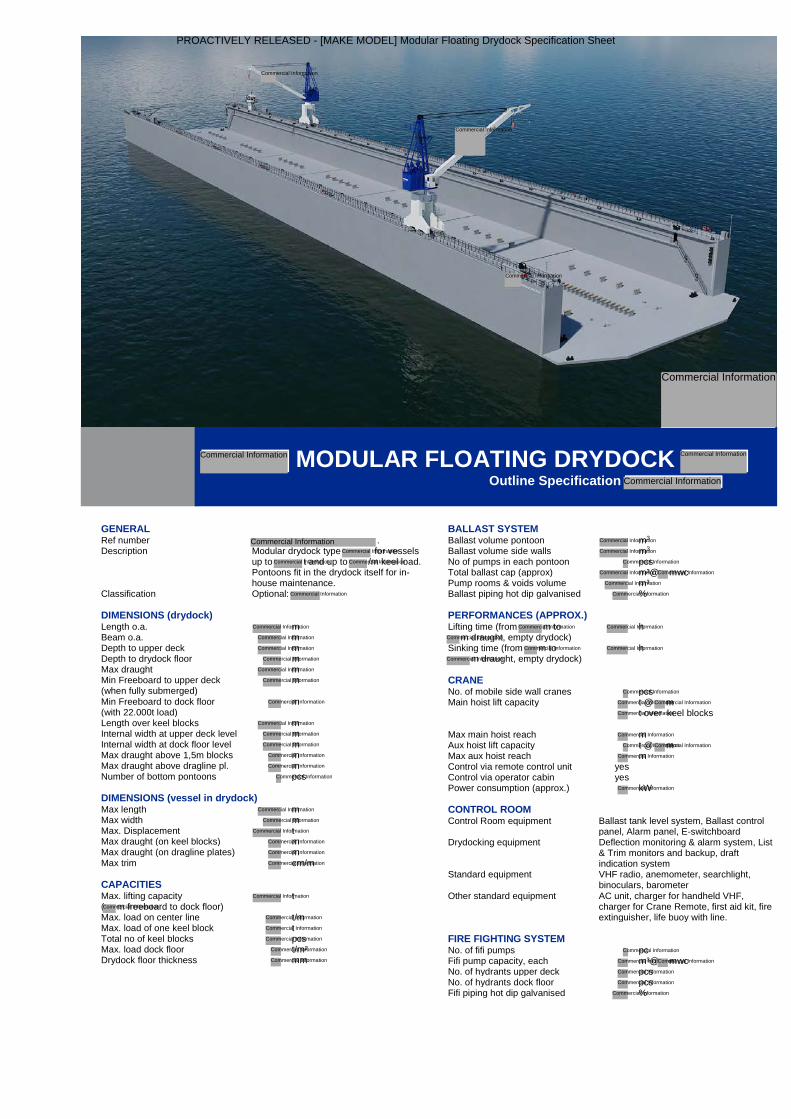
GENERAL Ref number .Description Modular drydock type for vessels
up to t and up to /m keel load.Pontoons fit in the drydock itself for in-house maintenance.
Classification Optional:
DIMENSIONS (drydock) Length o.a. m Beam o.a. m Depth to upper deck m Depth to drydock floor m Max draught m Min Freeboard to upper deck (when fully submerged)
m
Min Freeboard to dock floor (with 22.000t load)
m
Length over keel blocks m Internal width at upper deck level m Internal width at dock floor level m Max draught above 1,5m blocks m Max draught above dragline pl. m Number of bottom pontoons pcs
DIMENSIONS (vessel in drydock) Max length m Max width m Max. Displacement t Max draught (on keel blocks) m Max draught (on dragline plates) m Max trim cm/m
CAPACITIES Max. lifting capacity ( m freeboard to dock floor)
t
Max. load on center line t/m Max. load of one keel block t Total no of keel blocks pcs Max. load dock floor t/m² Drydock floor thickness mm
BALLAST SYSTEM Ballast volume pontoon m3 Ballast volume side walls m3 No of pumps in each pontoon pcs Total ballast cap (approx) m³@ mwc Pump rooms & voids volume m³ Ballast piping hot dip galvanised %
PERFORMANCES (APPROX.) Lifting time (from m to
m draught, empty drydock) h
Sinking time (from m to m draught, empty drydock)
h
CRANE No. of mobile side wall cranes pcs Main hoist lift capacity t @ m
t over keel blocks
Max main hoist reach m Aux hoist lift capacity t @ m Max aux hoist reach m Control via remote control unit yes Control via operator cabin yes Power consumption (approx.) kW
CONTROL ROOM Control Room equipment Ballast tank level system, Ballast control
panel, Alarm panel, E-switchboard Drydocking equipment Deflection monitoring & alarm system, List
& Trim monitors and backup, draft indication system
Standard equipment VHF radio, anemometer, searchlight, binoculars, barometer
Other standard equipment AC unit, charger for handheld VHF, charger for Crane Remote, first aid kit, fire extinguisher, life buoy with line.
FIRE FIGHTING SYSTEM No. of fifi pumps pc Fifi pump capacity, each m³@ mwc No. of hydrants upper deck pcs No. of hydrants dock floor pcs Fifi piping hot dip galvanised %
MODULAR FLOATING DRYDOCK Outline Specification
PROACTIVELY RELEASED - [MAKE MODEL] Modular Floating Drydock Specification Sheet
Commercial Information
Commercial Information
Commercial Information
Commercial Information
Commercial Information
Commercial Information
Commercial Information
Commercial Information
Commercial Information
Commercial Information
Commercial Information
Commercial Information
Commercial Information
Commercial Information
Commercial Information
Commercial Information
Commercial Information
Commercial Information
Commercial Information
Commercial Information
Commercial Information
Commercial Information
Commercial Information
Commercial Information
Commercial Information
Commercial Information
Commercial Information
Commercial Information
Commercial Information
Commercial InformationCommercial Information
Commercial Information Commercial Information
Commercial Information
Commercial Information
Commercial Information
Commercial Information
Commercial Information
Commercial Information
Commercial Information
Commercial InformationCommercial Information
Commercial Information
Commercial Information
Commercial Information
Commercial Information
Commercial Information
Commercial Information
Commercial Information
Commercial Information
Commercial InformationCommercial Information
Commercial Information
Commercial Information
Commercial Information
Commercial Information
Commercial Information
Commercial Information
Commercial Information
Commercial Information
Commercial Information
Commercial Information
Commercial Information
Commercial Information
Commercial Information
Commercial Information
© No part of the leaflet may be reproduced in any form, by print, photo print, microfilm, or any other means, without the written permission from
MODULAR FLOATING DRYDOCK Outline Specification
PROACTIVELY RELEASED - [MAKE MODEL] Modular Floating Drydock Specification Sheet
Commercial Information
Commercial Information
Commercial Information
Commercial Information
Commercial Information
Commercial Information
Commercial Information
Commercial Information
Commercial Information
Commercial Information
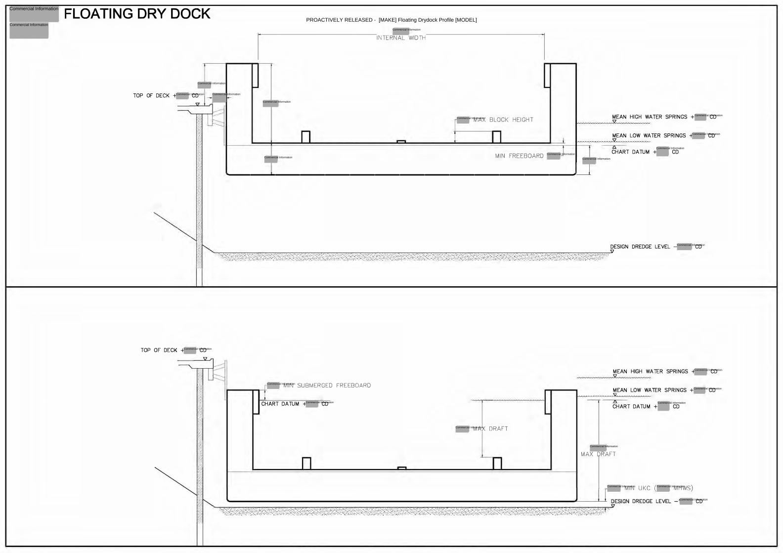
FLOATING DRY DOCK
TOP OF DECK + CD
TOP OF DECK + CD
INTERNAL WIDTH
MAX BLOCK HEIGHT
MIN FREEBOARD
MEAN HIGH WATER SPRINGS + CD
MEAN LOW WATER SPRINGS + CD
CHART DATUM + CD
----�����������--�
MIN SUBMERGED FREEBOARD
CHART DATUM + CD
MAX DRAFT
DESIGN DREDGE LEVEL - CD
MEAN HIGH WATER SPRINGS + CD :sz
MEAN LOW WATER SPRINGS + CD
CHART DATUM + CD
MAX DRAFT
MIN UKC ( MHWS)
DREDGE LEVEL -1 CD
PROACTIVELY RELEASED - [MAKE] Floating Drydock Profile [MODEL]
Commercial Information
Commercial Information
Commercial Information
Commercial Information
Commercial Information
Commercial Information
Commercial InformationCommercial Information
Commercial Information
Commercial Information
Commercial Information
Commercial Information
Commercial Information
Commercial Information
Commercial Information
Commercial Information
Commercial Information
Commercial Information
Commercial Information
Commercial Information
Commercial Information
Commercial Information Commercial Information
Commercial Information
Commercial Information
Commercial Information
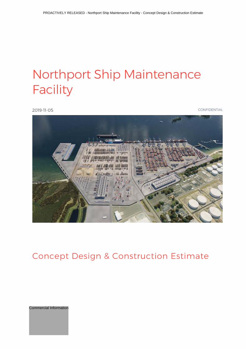
Northport Ship Maintenance Facility
Concept Design & Construction Estimate
2019-11-05
CONFIDENTIAL
PROACTIVELY RELEASED - Northport Ship Maintenance Facility - Concept Design & Construction Estimate
Commercial Information

i
Contact Details
Document Details: Date: 05 November 2019 Reference: Status: Final Revision: 01
Prepared by
Reviewed by
Approved for release by
ELY RELEASED - Northport Ship Maintenance Facility - Concept Design & Construction Estimate Commercial Information
Privacy of Natural Persons
Privacy of Natural Persons
Privacy of Natural Persons
Privacy of Natural Persons
Commercial Information
ii
Contents Executive Summary ..................................................................................................................................................................................................... 1
1 Introduction ........................................................................................................................................................................................................ 3
2 Scope of Engineering Workstream ................................................................................................................................................. 4
3 User Requirements ....................................................................................................................................................................................... 5
3.1 High-level overview of reclamation .................................................................................................................................. 5
3.2 High-level overview of the dry dock operation ...................................................................................................... 5
3.3 Berth (and immediate surroundings) requirements ....................................................................................... 6
3.4 Dolphin requirements ................................................................................................................................................................ 6
3.5 Maintenance facilities & hard standing (away from berth faces) requirements ....................... 7
3.6 Geotechnical and associated construction aspects .......................................................................................... 7
3.7 Consenting / Environmental ................................................................................................................................................. 8
3.8 Material preferences .................................................................................................................................................................... 8
3.9 Agreed assumptions .................................................................................................................................................................... 8
4 Project Constraints and Key Issues ............................................................................................................................................... 10
5 Inputs from other Sources ..................................................................................................................................................................... 11
6 Design Methodology ................................................................................................................................................................................. 12
7 Importance Level and Seismic Issues ......................................................................................................................................... 13
7.1 Importance Level ........................................................................................................................................................................... 13
7.2 Seismic Issues ................................................................................................................................................................................... 13
8 Preliminary Geotechnical Analysis ................................................................................................................................................. 14
9 Options and Proposed Concept ...................................................................................................................................................... 15
9.1 Options Considered ..................................................................................................................................................................... 15
9.2 Selection Criteria ............................................................................................................................................................................ 15
9.3 Initially Proposed Concept Design ................................................................................................................................. 15
10 Proposed Construction Methodology ........................................................................................................................................ 17
11 Proposed Construction Programme ............................................................................................................................................ 19
12 Construction Cost Estimate ............................................................................................................................................................... 20
13 Opportunities & Risks Summary ...................................................................................................................................................... 21
14 Recommendations .................................................................................................................................................................................... 24
Appendix A Proposed Concept Drawings .......................................................................................................................................... 25
ELY RELEASED - Northport Ship Maintenance Facility - Concept Design & Construction Estimate
Commercial Information
Commercial Information

iii
Appendix B Proposed Concept - Estimate ....................................................................................................................................... 26
VELY RELEASED - Northport Ship Maintenance Facility - Concept Design & Construction Estimate
Commercial Information
Commercial Information
Northport Ship Maintenance Yard Design & Construction Estimate
1
Executive Summary Northport has excellent recent technical and construction management experience. The port is less than 20 years old, with the most recent berth extension in 2007, and the hardstanding area doubled over the past decade. Northport has proven their capability in technical, construction, and maintenance management. Northport is a modern port design that meets high environmental standards. The proposed ship maintenance facility adopts Northport’s proven construction and operational experience of sheet piling, drainage, lighting, pavement, cathodic protection of steel, fenders and bollards, etc.
This report contains the findings from of intensive investigation to establish a concept design and cost estimate for the civil infrastructure to enable a ship maintenance facility at Northport to be constructed. The objective of this report is to support a funding application for the consenting, detailed design and construction phase.
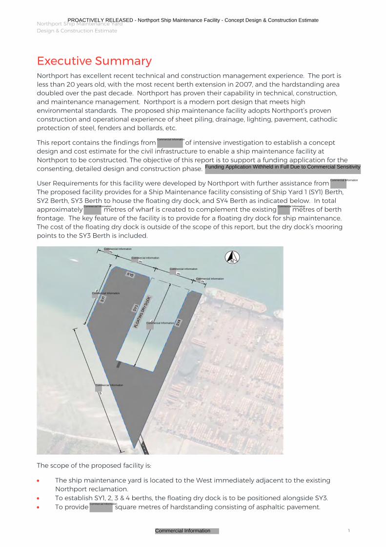
User Requirements for this facility were developed by Northport with further assistance from The proposed facility provides for a Ship Maintenance facility consisting of Ship Yard 1 (SY1) Berth, SY2 Berth, SY3 Berth to house the floating dry dock, and SY4 Berth as indicated below. In total approximately metres of wharf is created to complement the existing metres of berth frontage. The key feature of the facility is to provide for a floating dry dock for ship maintenance. The cost of the floating dry dock is outside of the scope of this report, but the dry dock’s mooring points to the SY3 Berth is included.
The scope of the proposed facility is:
The ship maintenance yard is located to the West immediately adjacent to the existing Northport reclamation.
To establish SY1, 2, 3 & 4 berths, the floating dry dock is to be positioned alongside SY3. To provide square metres of hardstanding consisting of asphaltic pavement.
PROACTIVELY RELEASED - Northport Ship Maintenance Facility - Concept Design & Construction Estimate
Commercial Information
Commercial Information
Commercial Information Commercial Information
Commercial Information
Commercial Information
Commercial Information
Commercial Information
Commercial Information
Commercial Information
Commercial Information
Commercial Information
Commercial Information
Funding Application Withheld in Full Due to Commercial Sensitivity
Northport Ship Maintenance Yard Design & Construction Estimate
2
Approximately metres in length of a king-pile sheet-pile wall to contain the hardstanding and provide wharf frontage including bollards and fenders.
The berth frontage is retained by king-pile and sheet-pile combined wall (combi-pile wall) that is tied back by anchors into the hardstanding area.
There are 3 mooring points to accommodate the floating dry dock, a vehicle entrance ramp is also included to provide access to the floating dry dock from the south.
Along the southern side diagonal of the site is a rock revetment retaining wall including a metre high visual and noise mitigation wall.
All stormwater is retained within the ship maintenance facility, mechanically treated, and then discharged into the existing Northport stormwater management system.
To extend the existing ship turning basin requires approximately cubic metres of dredging, approximately % is utilised in the construction, the other % is surplus to the project.
Services such as waste water, potable water, fire protection, power, general yard lighting are included, there are no buildings.
On the southern tip of SY1 there is a public fishing jetty with foot traffic access for the public. A metre long access road from the port boundary to Marsden Bay Drive through
Marsden Maritimes Holding property.
From a Building Code perspective, an Importance Level 2 has been adopted for the facility, meaning it does not have a guaranteed post disaster function.
From the geotechnical information available the key differences compared to the existing reclamation are that this area has a higher level of variability, with clay layers present at critical depths. Also, the density of the upper layers and reclaimed sand fill require ground improvement.
different concepts were considered. The proposed concept based on the selection criteria adopted was a steel combi-pile wall with one level of tie backs above low tide level with as much length as possible constructed in the dry. Where this is not possible,
, a more expensive construction sequence utilising floating platforms is proposed.
The construction period is approximately years. prior to construction allows for detailed design, early
procurement of steel, Whangarei District Council Building Consent and any additional Resource Consent processing, and contractor mobilisation.
The second most significant risk is the ground conditions.
Refer to Section 13 for further detail.
In summary:
1. The proposed ship maintenance facility construction cost estimate is $ + GST. The additional allowance for Escalation and Resource Consent costs, which are not included in the construction cost estimate.
2. For a project of this nature it is recommended to allow the Contractor sufficient flexibility to redesign the works to match their skills and resources and thus provide added value.
3.
4.
5. The greatest opportunity is the ability to obtain a Resource Consents to allow construction of most of the works in the dry.
PROACTIVELY RELEASED - Northport Ship Maintenance Facility - Concept Design & Construction Estimate
Commercial Information
Commercial Information
Commercial Information
Commercial Information
Commercial Information Commercial Information
Commercial Information
Commercial Information
Commercial Information
Commercial Information
Commercial Information
Commercial Information
Commercial Information
Commercial InformationCommercial Information
Commercial Information

Northport Ship Maintenance Yard Design & Construction Estimate
3
1 Introduction Northport, working in conjunction with stakeholders, has successfully applied to the Provincial Growth Fund for funding to develop a concept for a Ship Maintenance Facility together with the completion of associated studies, investigations, construction cost estimates, business case and other relevant documentation.
This work is being undertaken as a series of workstreams coordinated and managed by Northport, one of which is this engineering workstream including concept design and cost estimate for the facility. The cost estimate excludes the floating dry dock.
Stakeholder User Requirements for the facility have been provided to by Northport through a workshop, Skype sessions and a series of questions and answers.
PROACTIVELY RELEASED - Northport Ship Maintenance Facility - Concept Design & Construction Estimate
Commercial Information
Commercial Information
Northport Ship Maintenance Yard Design & Construction Estimate
4
2 Scope of Engineering Workstream The Ship Maintenance Facility concept development has a number of workstreams that are being undertaken by several different parties. These are set out in the application to the Provincial Growth Fund (PGF) dated 30 November 2018 and are not repeated here.
The funding provided is to complete an in-depth operational feasibility study of the preferred location for the ship repair/ dry dock facility which will require a full risk assessment, design and capability review as set out in question 15 (under Part B: Project Description) of the PGF application.
The workstream undertaken by is:
Concept design of the civils/ marine infrastructure needed for the facilitation and operation of the proposed floating dry dock (Note the selection and procurement of the floating dry dock is outside this scope of work, as is the operational layout which has been developed by Northport and other stakeholders)
Concept construction methodology, works programme, and construction cost estimate
Project memorandum PM01 provides further detail on:
Outputs required Programme for delivery Proposed Methodology Discussion on technical aspects relating to the outputs, and Highlights some of the risks as seen at the start of the concept development
It should be noted that this phase of the work only covers the development of a proposed concept for this ship maintenance facility, and an estimate based on the proposed concept. It does not constitute a preliminary design for the ship maintenance facility.
PROACTIVELY RELEASED - Northport Ship Maintenance Facility - Concept Design & Construction Estimate
Commercial Information
Commercial Information
Funding Application Withheld in Full Due to Commercial Sensitivity
Funding Application Withheld in Full Due to Commercial Sensitivity
Northport Ship Maintenance Yard Design & Construction Estimate
5
3 User Requirements Stakeholder User Requirements for the ship maintenance facility have been provided to by Northport through a number of engagement means, namely:
Workshop on site (12/09/2019) Interactive Skype sessions Emails and phone calls containing a series of questions from with answers from
Northport have not held any discussions with any other stakeholder other than Northport
The record of user requirements serves as a written record of key discussions and decisions made, to enable the successful completion of the concept design stage.
The record also provides transparency concerning the reasoning at the time of the discussion, allowing for the opportunity to revisit decisions made, should there be a need to do so in the subsequent stages.
The key user requirements summarised below demonstrate the final decisions captured as part of completing the abovementioned stakeholder engagements.
3.1 High-level overview of reclamation
The proposed reclamation which forms the ship maintenance facility, is to have a design life of at least years, which is in line with the design life of the drydock.
Additional durability interventions can be undertaken at years to enable the ship maintenance facility to achieve -year design life.
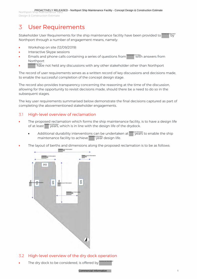
The layout of berths and dimensions along the proposed reclamation is to be as follows:
3.2 High-level overview of the dry dock operation
The dry dock to be considered, is offered by
PROACTIVELY RELEASED - Northport Ship Maintenance Facility - Concept Design & Construction Estimate
Commercial Information
Commercial Information
Commercial Information
Commercial Information
Commercial Information
Commercial Information
Commercial Information
Commercial Information
Commercial InformationCommercial Information
Commercial Information Commercial Information
Commercial Information
Commercial Information
Northport Ship Maintenance Yard Design & Construction Estimate
6
Dimensions are x m Maximum displacement that can be handled by the dry dock is tonnes The dry dock has a submerged draft of m Keel blocks will sit on the deck of the dry dock by means of gravity only – they will not
be fixed to the structure
The drydock is to be located along SY3, connected at 3 points
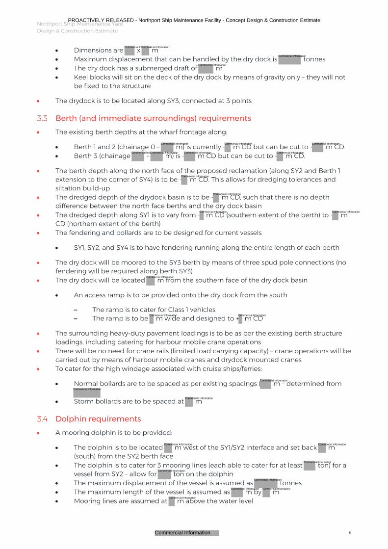
3.3 Berth (and immediate surroundings) requirements
The existing berth depths at the wharf frontage along:
Berth 1 and 2 (chainage 0 – m) is currently - m CD but can be cut to - m CD. Berth 3 (chainage – m) is - m CD but can be cut to - m CD.
The berth depth along the north face of the proposed reclamation (along SY2 and Berth 1 extension to the corner of SY4) is to be - m CD. This allows for dredging tolerances and siltation build-up
The dredged depth of the drydock basin is to be - m CD, such that there is no depth difference between the north face berths and the dry dock basin
The dredged depth along SY1 is to vary from - m CD (southern extent of the berth) to - m CD (northern extent of the berth)
The fendering and bollards are to be designed for current vessels
SY1, SY2, and SY4 is to have fendering running along the entire length of each berth
The dry dock will be moored to the SY3 berth by means of three spud pole connections (no fendering will be required along berth SY3)
The dry dock will be located m from the southern face of the dry dock basin
An access ramp is to be provided onto the dry dock from the south
– The ramp is to cater for Class 1 vehicles – The ramp is to be m wide and designed to + m CD
The surrounding heavy-duty pavement loadings is to be as per the existing berth structure loadings, including catering for harbour mobile crane operations
There will be no need for crane rails (limited load carrying capacity) – crane operations will be carried out by means of harbour mobile cranes and drydock mounted cranes
To cater for the high windage associated with cruise ships/ferries:
Normal bollards are to be spaced as per existing spacings ( m – determined from
Storm bollards are to be spaced at m
3.4 Dolphin requirements
A mooring dolphin is to be provided:
The dolphin is to be located m west of the SY1/SY2 interface and set back m (south) from the SY2 berth face
The dolphin is to cater for 3 mooring lines (each able to cater for at least ton) for a vessel from SY2 – allow for ton on the dolphin
The maximum displacement of the vessel is assumed as tonnes The maximum length of the vessel is assumed as m by m Mooring lines are assumed at m above the water level
PROACTIVELY RELEASED - Northport Ship Maintenance Facility - Concept Design & Construction Estimate
Commercial Information
Commercial InformationCommercial Information
Commercial Information
Commercial Information
Commercial Information Commercial Information Commercial Information
Commercial InformationCommercial Information Commercial Information Commercial Information
Commercial Information
Commercial Information
Commercial Information Commercial Information
Commercial Information
Commercial InformationCommercial Information
Commercial Information
Commercial Information
Commercial Information
Commercial Information Commercial Information
Commercial Information
Commercial Information
Commercial Information
Commercial Information Commercial Information
Commercial Information
Northport Ship Maintenance Yard Design & Construction Estimate
©WSP New Zealand Limited 2019 7
No mooring study has been undertaken at this stage for the dolphin to ascertain horizontal arcs and vertical inclinations
3.5 Maintenance facilities & hard standing (away from berth faces) requirements
The proposed facility operator will require basic buildings such as offices, ablutions, small workshops, lunch rooms, etc.
The following services will need to be supplied:
Water:
– Stormwater infrastructure (subsurface) – which can flow into the existing stormwater management system that is designed for a -year Annual Reoccurrence Interval (ARI)
– The stormwater infrastructure will need to cater for treatment prior to being discharged into the existing stormwater management system
– Sewer infrastructure (including infrastructure to cater for waste water contained within the floating dry dock)
– Potable water and Firefighting infrastructure
Power:
– kVA power supply; Hz power supply for vessels – Substation, which should be located in the vicinity of SY1, SY2, and SY3
Lighting:
– The existing Port grid layout for lights is to be extended along the proposed reclamation
– It is assumed that the dry dock is self-contained for lighting – Lights to be m high – It is assumed that any additional lighting required by the shipyard operator will
need to be supplied on a case-by-case basis
All services need to be located away from crane operation locations – the harbour mobile cranes will operate within m of the berth face
The finished level of the reclamation is to be + m CD, which ties into the existing berth finish levels (along the perimeter)
Allowance is to be made for surface water drainage falls at and (where appropriate) – the reclamation is required to be as flat as possible
The existing pavement design is deemed appropriate, given the good track record of the existing pavements, consisting of :
mm AC mm stabilised Basecourse A concrete beam will run along the perimeter of the proposed combi pile wall
The existing noise wall will remain in its current location The proposed reclamation will require an additional visual and noise wall and security fence
along the southwestern border of the reclamation
3.6 Geotechnical and associated construction aspects
There is an expectation that the structure will still be serviceable after an earthquake with an annual probability of exceedance greater that
The structure is to be designed as an Importance Level 2 structure
PROACTIVELY RELEASED - Northport Ship Maintenance Facility - Concept Design & Construction Estimate
Commercial Information Commercial Information
Commercial Information
Commercial Information
Commercial Information
Commercial Information
Commercial Information Commercial Information
Commercial Information
Commercial Information
Commercial Information
Northport Ship Maintenance Yard Design & Construction Estimate
8
The construction sequence proposed must be constructible, with the primary objective to obtain a construction cost estimate and an associated high-level construction programme
3.7 Consenting / Environmental
Dredge/sediment plumage during construction will needed to be managed and acceptable limits will be determined by the Resource Consent
The proposed construction technique limits the dredge/sediment plumage A public fishing jetty and access route is to be provided at the southern extent of SY1, similar
to the existing jetty
3.8 Material preferences
Northport has indicated that they prefer the following berth structures along the proposed western expansion:
SY1 – Sheet piles and fendered (same structures as Berth 3) SY2 and Berth 1 extension to the interface with SY4 – open piled structure (same
structures as Berth 1 and 2) SY3 and SY4 - combi pile wall and tied back deadman is acceptable
The sheet piles to be painted in the tidal and splash zones and have cathodic protection ICCP to be installed (sheet piles and concrete reinforcing will therefore need to be
electrically continuous) The proposed concept design has been based on a technique that allows for a large portion
of the construction work to be completed off of land (in the form of reclamation) while still (at this concept design stage) demonstrating confidence in construction costs, constructability, and long-term performance
3.9 Agreed assumptions
Following the completion of preliminary vessel handling simulations, the following assumptions for the concept design were made in order to inform the engineering design:
It is assumed that the dry dock and its connections will perform winching Breasting dolphins are provided at the entry points to the dry dock basin to avoid damage;
the concept fendering system is to cater for the following:
Maximum vessel displacement of a vessel entering the drydock is tonnes Maximum approach velocity is knots Impact angle is degrees
It is assumed that the SY1/SY2 corner is bevelled and contains fenders (i.e. roller fenders)
This allows vessels the ability to lean on the fendering and be rotated around the fendering
Vessel velocities are assumed to be knots in this instance Impact angle is degrees Maximum vessel displacement is assumed to be tonnes
Cost rates for dredging were provided by Northport It is assumed that the mobile dredging operation will fit around the construction
requirements. Examples of hopper dredger vessels are as follows:
The Albatross dredge has a - m draught with - m3 capacity The Fairway dredge has a m draught with m3 capacity
PROACTIVELY RELEASED - Northport Ship Maintenance Facility - Concept Design & Construction Estimate
Commercial Information
Commercial Information
Commercial Information
Commercial Information
Commercial Information
Commercial Information
Commercial Information
Commercial InformationCommercial Information
Commercial InformationCommercial InformationCommercial InformationCommercial Information

Northport Ship Maintenance Yard Design & Construction Estimate
9
For cost estimating purposes, the worst case scenario was assumed, where excess dredging would be dumped offshore
ICCP installations will be needed. Cost information was provided by Northport
Need to include for the dry dock within the overall cathodic protection system In addition to ICCP, painting of the tidal and splash zones is also required
The estimate is to assume current rates – do not allow for escalation
PROACTIVELY RELEASED - Northport Ship Maintenance Facility - Concept Design & Construction Estimate
Commercial Information
Northport Ship Maintenance Yard Design & Construction Estimate
10
4 Project Constraints and Key Issues There are a number of project constraints. The key constraints are briefly discussed below.
Northport’s “Vision for Growth” includes a ha expansion to the west of the existing Port, the ship maintenance facility is to fit within this area.
The approximately ha footprint requires about m3 of fill to create the reclamation. It is cost effective to obtain the fill material from the nearby dredging required to create the berth pockets/ turning basin and floating dry dock basin.
An operational constraint is the existing berths, and more critically Berth 1, which must remain operational at all times both during construction and during operation of the dry dock.
The dimensions and operational requirements of a range of possible floating dry docks has been assessed by Northport and advised that the design is to be based on a floating dry dock. We have utilised what information the manufacturer was prepared to provide at the time of undertaking the concept design.
Vessel simulations have been provided by Northport’s in-house simulator, the geometry and detailed layout of the facility is based on preliminary simulation runs undertaken. These simulations are based on selected vessels likely to be maintained in the dry dock.
Vessel information on existing Navy vessels has been provided, and the concept design of the berths primarily used by Navy is based on this information.
The mooring of the floating dry dock in the basin is based on knot wind speed provided by but Northport have asked that this be increased. A figure of knots has been used.
The preliminary design phase was to be weeks, however to meet funding requirements timeframe of for an updated construction cost estimate a concept design and cost estimate has been provided. To provide confidence in the updated construction cost estimate, the development of a proposed concept design (including geotechnical testing completed by Northport utilising ) together with an associated construction methodology and programme was completed within a period, this necessitated parallel workstreams and the inclusion of risks and opportunities (see Section 13).
PROACTIVELY RELEASED - Northport Ship Maintenance Facility - Concept Design & Construction Estimate
Commercial Information
Commercial InformationCommercial Information
Commercial Information
Commercial InformationCommercial Information
Commercial Information
Commercial Information
Commercial Information
Commercial Information
Commercial InformationCommercial Information
Commercial Information
Northport Ship Maintenance Yard Design & Construction Estimate
11
5 Inputs from other Sources Ideally, at the start of the concept design phase, inputs would be available from other Northport suppliers working on their respective workstreams, however, this was not possible due to the
time frame in which the concept design and construction estimate needed to be completed. Therefore, should the project progress, like all projects, there will be review and refinement of the cost estimate. Other sources are:-
Hydrodynamic study including sediment transport in the dry dock
Geotech investigations and laboratory testing results, the final report was available as at 25th October at the end of concept design. Further testing of the unexpected clay layers is recommended
Additional vessel simulations continue to be undertaken by Northport, this may further optimise the dredging
Consenting strategy may require design or construction method refinements
Ship maintenance yard users may also require design refinements, to date these have been provided by Northport
PROACTIVELY RELEASED - Northport Ship Maintenance Facility - Concept Design & Construction Estimate
Commercial Information
Commercial Information
Final Report Withheld in Full Due to Commercial Sensitivity
Northport Ship Maintenance Yard Design & Construction Estimate
12
6 Design Methodology The concept design methodology adopted was:
1. Collect and assess the Stakeholder User Requirements and the proposed layout. The more important user requirements needed to advance this workstream were provided by Northport at the workshop on 12 September 2019 and implications discussed; the remainder were provided via Skype sessions, and specific requests for information.
2. Develop views on issues of the status of the facility in terms of the coastal and marine requirements.
3. Gain Northport agreement to the adoption of Importance Levels used to develop design loadings.
4. Incorporate the Stakeholder User Requirements provided by Northport into the design.
5. Assimilate the existing geotechnical information and where possible include results from the investigations being undertaken in parallel with the engineering design.
6. Review and where appropriate incorporate previous Northport wharf designs for re-use within the new wharf and floating dry dock basin; this includes an assessment of the seismic liquefaction, and any construction issues specific to this site.
7. Develop a proposed concept design to satisfy the Stakeholder User Requirements, and comment on buildability/construction issues.
8. Identify where further work may be required in the following stages.
9. Develop the Functional Requirements for the final concept design.
10. Develop an updated construction cost estimate.
11. Comment on cost opportunities and risks.
PROACTIVELY RELEASED - Northport Ship Maintenance Facility - Concept Design & Construction Estimate
Commercial Information
Commercial Information
Northport Ship Maintenance Yard Design & Construction Estimate
13
7 Importance Level and Seismic Issues
7.1 Importance Level
Project Memorandum PM02 discusses the impact on the concept design for the adoption of various Importance Levels (as set out in AS/NZS1170.0 2002), asset life, and any implications of the CDEMA on this facility.
It was agreed with Northport that the development of the concept design is to be based on:
The facility does not have a post disaster function
An Importance Level 2 is to be adopted
Asset life is to be at least years
7.2 Seismic Issues
The seismic issues at the site are dictated by the prevailing seismic hazard at this location, and the ability of the reclamation to sustain the design levels of shaking with an acceptable level of damage.
The design levels of shaking are such that liquefaction of the upper layers of the sea bed and reclamation fill that is deposited through a water column cannot be discounted and some densification of these layers will be required.
Around the perimeter of the reclamation the level of densification of the sand layers down to approximately RL - m is variable, and vibro-compaction is considered the most cost-effective means of improving this. However, due to the variability of the materials encountered in the September/October geotechnical investigation drilling, it may be necessary to also use other methods, such as stone columns in selected areas.
The proposed design of the reclamation bund and waterfront structures are sufficiently strong to contain the liquefied reclamation materials post-earthquake and prevent excessive lateral deformations.
PROACTIVELY RELEASED - Northport Ship Maintenance Facility - Concept Design & Construction Estimate
Commercial Information
Commercial Information
Commercial Information
Northport Ship Maintenance Yard Design & Construction Estimate
14
8 Preliminary Geotechnical Analysis Work on the concept design initially utilised the results of investigations undertaken for Berths 1, 2, and 3 with the assumption that ground conditions in the area of the floating dry dock basin would be similar. Results of the drilling work in October 2019 undertaken concurrently to this engineering workstream was to be utilised if it became available in time.
The investigations for Berths 1, 2, and 3 indicated that sands would be the predominate material encountered with isolated silty sand and clayey sand layers. Analytical work for the preferred combi-pile wall with tie backs proceeded on this basis utilising the vibro-compaction improved properties of the sand layers.
When the results of the concurrent geotechnical investigation drilling work became available, it was apparent that the site was much more variable than first assumed, and there are clay layers extending across the site at the level of the base of the dry dock basin. The upper section of the clay layer was relatively soft, becoming firmer with depth. The presence of weak clay extending in front of the combi-pile wall and into the basin required further assessment and analysis and was found to place higher bending demands into the combi-pile wall.
The concept design and analyses are based on some limited soil property data. The proposed CPT testing from floating plant failed to achieve significant penetration of the sea floor. Therefore, we relied on the available correlations between soil properties and the SPT tests performed down the bore holes.
The preferred design is sensitive to the undrained shear strength of the clay layer. It is expected that further sampling and testing to derive the undrained shear strength of these silt/clay layers will be undertaken in the following design phase to confirm these material properties and refine the design.
PROACTIVELY RELEASED - Northport Ship Maintenance Facility - Concept Design & Construction Estimate
Commercial Information
Free and frank opinions
Northport Ship Maintenance Yard Design & Construction Estimate
15
9 Options and Proposed Concept
9.1 Options Considered
A number of options for the wharves and the floating dry dock basin were considered prior to arriving at a proposed concept. These were as follows:
Wharves similar to Berths 1 and 2 Twin combi-pile wall structure similar to Berth 3 Diaphragm wall with tieback anchors Interlocking circular caissons gravel or sand filled Single combi-pile wall with tieback anchors Typical marginal wharf
9.2 Selection Criteria
A number of criteria were considered when arriving at a proposed concept. These included:-
Targeting optimal cost Workable construction sequencing considering floating platforms and the use of divers The possibility for the need for ground improvement Ability to take advantage of the shallow water depth over the site (when compared to Berths
1, 2 & 3) and the opportunity to construct in the dry rather than over water The cost benefits of construction in the dry rather than over water Optimising materials required Consideration of contractor capability including labour and plant required The benefits of dredged fill from the vessel turning area into the reclamation The relatively low cost of rock/gravel from nearby quarries An acceptable programme and a limited period of exposure to construction noise The ability to modify the construction methodology without major changes to the concept
to address environmental constraints A robust approach to seismicity and liquefaction
9.3 Initially Proposed Concept Design
The initially proposed concept adopted was to create a temporary reclamation up to RL + m CD outside the western and norther berth faces, protect this from wave action during construction, and except for a small section in the northeast corner, after filling, construct the works in the dry. The temporary platform would then be removed as part of the dredging of the floating dry dock basin. The small section in the northeast corner would then be the only section that required the use of floating plant, and divers.
The benefits of this concept (excluding the northeast corner) are as follows:
Can be constructed in the dry Has very simple construction procedure, meaning construction will be cheaper No diving is required, and the tie backs constructed in the dry Requires dredging campaigns but this is considered acceptable given mismatch in cut
( cubic metres) to fill volumes ( cubic metres) Uses less concrete and steel materials, and hence reduced labour to install/ construct There is no need for a concrete deck, so none is provided The combi pile capping beam can accommodate both bollards and fender systems, with
storm bollards being located as separate elements further back from the berth face Ground improvement is expected to be economical and straight forward The concept can accommodate other ground improvement techniques
PROACTIVELY RELEASED - Northport Ship Maintenance Facility - Concept Design & Construction Estimate
Commercial Information
Commercial Information
Commercial InformationCommercial Information
Commercial Information

Northport Ship Maintenance Yard Design & Construction Estimate
16
The concept can be adjusted in geometry to cater for minor changes in User Requirements without necessitating a change in concept
Durability requirements can be readily addressed using proven technologies A separate mooring structure for the floating dry dock can be accommodated within the
basin in a straight forward manner
The initially proposed concept was then revised to take into account the likely requirements for a Resource Consent with the main factors being The revised concept allows for enclosing the reclamation area with either a combi-pile wall, or rock revetment, or a combination of the two, prior to commencement of reclamation. Drawings of the final preferred concept is contained in Appendix A.
PROACTIVELY RELEASED - Northport Ship Maintenance Facility - Concept Design & Construction Estimate
Commercial Information
Commercial Information
Commercial Information
Northport Ship Maintenance Yard Design & Construction Estimate
17
10 Proposed Construction Methodology Northport has excellent recent construction management experience including proven capability in technical, construction, and maintenance management. Northport is a modern port design that meets high environmental standards. The ship maintenance facility adopts Northport’s proven techniques of sheet piling, drainage, lighting, pavement, cathodic protection of steel, etc.
The construction summary methodology is:
1. Enclosing the hard-standing area including the dry dock basin. This requires the diagonal rock revetment to the south, the combi-pile walls for SY1, SY2 and temporary sheet piling across the entrance to the dry dock basin and sealing off against the existing Berth 1
2. Filling the site with dredged material from the turning basin
3. Install the dry dock basin perimeter combi-pile wall from on dry reclaimed land
4. Removal of the material within the dry dock basin to create the basin, followed by the removal of the entrance temporary sheet pile wall
5. In excess of approximately cubic metres of dredged sand is at this stage costed for disposal to waste (location to be determined), while approximately cubic metres is used in the reclamation
6. Hard standing and services are similar in nature to Northport’s proven existing infrastructure
The following is a more detailed description of activities:
Sea Wall - this is constructed with traditional earthworks plant ( m3 delivery trucks, ton digger) working forward from dry land at the southern end. Geotextile will be laid over the wet areas prior to the core being placed. The seawall will be built m wide to allow trucks to pass each other. The core will be constructed from greywacke ( ) formed to final level with trucks progressively driving over it to deliver rock to the digger at the advancing workface. Geotextile, filter rock, and rip rap will be placed immediately as the seawall advances.
Removal of Soft Clays along Combi-pile Wall – these will be pre-dredged by a cutter-suction dredger to spoil, possibly offshore.
Temporary Floating Breakwater – this will be constructed in m lengths on site in the form of - m vertical timber boards secured by a light steel framework to no. diameter mm steel tubes with closed ends. The floating breakwater sections will be tied to heavy duty temporary steel H-section piles driven into the seabed at approximately m centres. The purpose of the breakwater is to control the height/size of waves impacting the unsecured combi-pile wall during installation, in high winds/weather, preventing undue deflections/damage to the combi-pile wall.
Combi-pile Wall and Dead Man – this will be installed from water with a ton crane, vibro hammer, and hydraulic impact hammer working off a ton Jack Up Barge (JUB). The combi-pile wall king piles and intermediate sheet piles are m and m long, respectively. They will be procured and delivered to site by ship in full lengths with the sheet piles pre-clutched into pairs. Corrosion protection painting will be done prior to driving, with touch-ups to damaged areas being done after driving. A long purpose-built trailer will transfer the units from the storage yard to a loading area with a wharf face, where a ton crawler crane will load the units onto the service barge with a long lifting beam to control deflections. no. suitably sized service barges will be utilised to ensure that the JUB has a continuous supply of units moored to it.
The combi-pile wall units will be placed on the service barge on a purpose-made tilting cradle which will enable the units to be lifted at one end and transferred into a vertical position slung by the crane on the JUB. From there the unit will be placed into a “double-decker” piling gate welded to the JUB in the correct position and alignment of the combi-pile wall. Once in the gate, the
PROACTIVELY RELEASED - Northport Ship Maintenance Facility - Concept Design & Construction Estimate
Commercial Information
Commercial Information
Commercial Information
Commercial Information Commercial Information
Commercial Information
Commercial Information
Commercial Information Commercial InformationCommercial Information
Commercial Information Commercial Information
Commercial Information
Commercial Information
Commercial Information
Commercial Information Commercial Information
Commercial Information
Commercial Information
Northport Ship Maintenance Yard Design & Construction Estimate
18
crane will place a - ton vibro hammer onto the unit and vibrate it down to refusal (which may be on intermediate hard layers or it may go down to full design depth immediately). If necessary, a
- ton hydraulic impact hammer will be used to drive the units through any hard layers down to final design depth.
The dead man sheet pile wall will be installed in the same manner from the JUB, m from the combi-pile wall.
Whalers and tieback anchors to the dead man wall will be installed with assistance of the crane on the JUB and men working from workboats attaching ties to the connections.
Dredged sand will then be pumped directly into the m wide core between the dead man sheet pile wall and combi-pile wall. Working from the seawall end, access will be gained to the sand-filled combi-pile wall at level + m CD with a 150 ton crane, vibro hammer, and heavy duty H- section steel “lance” which will be used to vibro-compact the sand within the combi-pile wall core. The crane will progressively work forward over the stable compacted core.
Reclamation – once the combi-pile wall, temporary steel bulkhead, and seawall have sealed off the reclaimed area, the reclamation will be completed by pumping dredged sand directly into progressive “settlement ponds” formed by a dozer and digger, allowing surplus water to decant off at controlled positions on slightly lowered weirs on the pond walls. The sand will self-compact as it dries out.
Partial temporary reclamation into the dry dock basin berth area will be done sufficiently to allow the dry dock basin combi-pile wall to be installed from the reclaimed area.
Potential clay/silt layers will be separately pumped into “reserved” ponds from where it will be carted to spoil on land at approved tip sites after it has sufficiently dried to be handled.
Dry Dock Basin Combi-pile Wall – once the reclamation and vibro-compaction has been completed this wall will be installed from the reclamation by traditional land-based means.
When the dry dock basin combi-pile wall is installed the dry dock basin will be dredged out to spoil. A cutter suction dredger (CSD) will be assembled by crane in water in the dry dock basin , where after it will pump the sand into settlement ponds behind the south end of the seawall, from where it will be carted to spoil once dried.
Once the dry dock basin is fully dredged out the temporary bulkhead is then removed with crane and vibro hammer from the JUB onto a service barge and then transported back to land storage where it can be resold. The CSD can then travel out of the drydock basin to its next deployment.
Completion works – services, drainage, pavement layer works, and finishings can then be installed in the traditional manner.
Dolphin – the entire dolphin (piles, table top deck, furniture) will be constructed from the JUB. Concrete can be pumped along a pump-line supported on temporary piles from the northwest corner of the reclamation or delivered to the dolphin in a ready-mix truck driven onto a service barge.
PROACTIVELY RELEASED - Northport Ship Maintenance Facility - Concept Design & Construction Estimate
Commercial Information
Commercial InformationCommercial Information
Commercial InformationCommercial Information
Commercial Information
Commercial Information
Commercial Information
Northport Ship Maintenance Yard Design & Construction Estimate
19
11 Proposed Construction Programme It is likely that procurement in the Construction phase will allow the Contractor sufficient flexibility to optimise the design to suit their construction skills and resources, and thus cost. Therefore, it is assumed the Contractor would apply to the Whangarei District Council for a Building Consent and any modification to Resource Consents and as such will undertake the detailed design to support the Consents. The Design phase is likely to be to , followed by to Council approval of the Consents. This methodology assumes that Northport has already obtained a Resource Consent from the , and that this is not at this stage a critical path matter. The are not expected to require Development Contributions.
The Construction activity programme is approximately in duration.
1. In order to achieve a programme, based upon the proposed concept combi-pile wall design, two floating jack-up barges have been assumed. There are only two suitable jack-up barges in NZ. The estimate assumes a second barge will come from overseas, most likely from Australia.
2. Steel procurement may be a critical path item and will need to be considered early in the process and possibly procured during the preceding detailed design process.
3.
4. There are several factors that impact the programme, not the least being the actual methodology and design the appointed Contractor derives to suit his operations.
PROACTIVELY RELEASED - Northport Ship Maintenance Facility - Concept Design & Construction Estimate
Commercial Information
Commercial Information
Commercial InformationCommercial Information Commercial InformationCommercial Information
Commercial InformationCommercial Information
Commercial Information
Commercial Information
Northport Ship Maintenance Yard Design & Construction Estimate
20
12 Construction Cost Estimate The construction cost estimate has been prepared by of with inputs from Northport and has reviewed the estimate. Key assumptions are:
1. The construction cost estimate has been completed largely using first principle costing. Different contractors may select slightly differing methodologies, labour and plant rates, productivities and margins – resulting in different construction costs to varying degrees. As such this construction cost estimate must be viewed as a figure “for which the project can be constructed” in today’s market. It does not represent what the construction tender prices will be, but rather a figure for the determination of a construction cost estimate.
2. The costing is as at the last quarter of 2019.. Escalation of the estimate to reflect the actual cash flow timing of the activity has been excluded, but this will obviously be a cost to consider. Escalation could be in the order of - % (+$ ) to match the proposed construction programme timing.
3. FOREX for items such as steel supply, assumes last quarter 2019 existing rate.
4. Disposal of surplus dredged material assumes the cost of disposal offshore, this is a cost of approximately $ However, this material may be useful for
5. The Regional Council Resource Consent cost is outside the engineering scope, this is Northport’s responsibility. At this stage the Resource Consent pathway contains uncertainty and could cost of the order of $ to $
6. There are opportunities for improvement and thus may reduce cost, and also risks that have yet to be mitigated that may increase cost. This is normal for a project of this size and complexity at the concept design stage. The following section explains this more extensively.
and have been through a number of iterations and changes in scope of the estimate, however, typically the outcome of the construction cost estimate has remained consistent at $ to $ excluding GST for the project.
PROACTIVELY RELEASED - Northport Ship Maintenance Facility - Concept Design & Construction Estimate
Commercial Information
Commercial InformationCommercial Information
Commercial Information
Commercial Information
Commercial InformationCommercial InformationCommercial Information
Commercial Information Commercial Information
Commercial Information Commercial Information
Commercial InformationCommercial Information
Privacy of natural persons Commercial Information
Commercial Information
Northport Ship Maintenance Yard Design & Construction Estimate
21
13 Opportunities & Risks Summary During the concept design process a number of opportunities and risks have been identified. These relate to the ability to execute the works, the design scope and the construction cost estimate. Construction estimates should have allowance for risk. There are many methods for adjusting estimates to allow for risk.
Many government agencies have very detailed procedures for this including use of AtRisk Software, Monte Carlo analysis, etc, many of these processes are conservative. A weakness of many risk processes is the fact that they do not often consider cost savings, it is also unrealistic for all risks to actually occur, and likewise for all potential cost savings to be achieved.
The total of the identified risks is +$ and the total of the potential savings is $ The cost estimate allows for +$ of risk. The following are the risks and opportunities, together with the dollar figure included in the construction cost estimate for mitigation where appropriate.
1. A change in the geotechnical conditions in the area of the works from that encountered at Berths 1, 2 and 3 was identified as a risk prior to starting work. The results from the drilling work undertook by Northport in October 2019 was provided during the concept design period and confirmed the presence of clay layers that may require mitigation.
The results identified the presence of clay layers and clay lenses that were not present in Berth 1, 2 & 3 construction. The investigation did not test the clay layers sufficiently for results to be fully utilised in the concept design. Clay is notoriously variable in strength. This risk still exists and will need to be managed by further drilling and testing the clay. The variability of conditions across the site in respect of compactness of the sand
means there is a risk that additional ground improvement works to those included in the scope of work may well be required in some areas. This cannot be identified at this time because additional investigations are required to quantify material properties and variations in stratigraphy across the site. Allowance has been made for stone columns and vibro-compaction of sand in the construction cost estimate. (A possible $
risk).
2.
3.
4.
5.
PROACTIVELY RELEASED - Northport Ship Maintenance Facility - Concept Design & Construction Estimate
Commercial Information
Commercial Information Commercial Information
Commercial Information
Commercial Information
Commercial Information
Commercial Information
Commercial Information
Commercial Information
Commercial Information
Northport Ship Maintenance Yard Design & Construction Estimate
22
6.
7.
8.
9. Mooring of the dry dock, three major connections have been allowed for in the estimate,
however this has not be confirmed . (A possible $ risk). 10.
11.
12.
13.
14.
15.
16.
17.
PROACTIVELY RELEASED - Northport Ship Maintenance Facility - Concept Design & Construction Estimate
Commercial Information
Commercial Information
Commercial Information
Commercial Information
Commercial Information
Commercial Information
Commercial Information
Commercial Information
Commercial Information
Commercial Information
Commercial Information
Commercial Information
Commercial Information

Northport Ship Maintenance Yard Design & Construction Estimate
23
18. It is assumed the Development Contributions will not be required and that will support the development.
PROACTIVELY RELEASED - Northport Ship Maintenance Facility - Concept Design & Construction Estimate
Commercial Information
Commercial InformationCommercial Information
Northport Ship Maintenance Yard Design & Construction Estimate
24
14 Recommendations The following is recommended:
1. A construction cost estimate of $ + GST (which includes $ for risk) should be adopted for the proposed concept design. In addition to this Northport will make allowances for escalation and Resource Consent costs.
Initial high-level construction cost estimates for the development were $ + GST. Over the September/October period a number of scenarios for different construction techniques and structural forms confirmed a range between $ and $ for the construction estimate. This provides for a high level of confidence in the estimate.
2. For a project of this size it is recommended to allow the Contractor sufficient flexibility to design/redesign the works to match their skills and resources, and thus provide added value.
3. The highest and critical risk to the project is recognised as the
PROACTIVELY RELEASED - Northport Ship Maintenance Facility - Concept Design & Construction Estimate
Commercial Information
Commercial Information Commercial Information
Commercial Information
Commercial Information Commercial Information
Commercial Information

Appendix A Proposed Concept Drawings
PROACTIVELY RELEASED - Northport Ship Maintenance Facility - Concept Design & Construction Estimate
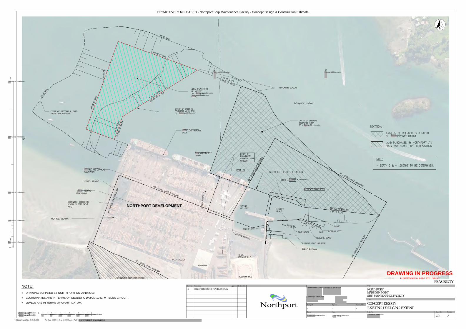
NORTHPORT DEVELOPMENT
0mm
mm
Scales Project No. Sheet. No.
Project
Sheet
Revision
Original Sheet Size A1 [841x594] Plot Date 2019-11-01 at 11:30:33 a.m. Path U:
Drawn
Approved Approved Date
DRAWING IN PROGRESS
PLOTTED ON 2019-11-1 AT 11:30 a.m.
Northport
NORTHPORTMARSDEN POINTSHIP MAINTENANCE FACILITY
CONCEPT DESIGNEXISTING DREDGING EXTENT
FEASIBILITY
C01 A
- - -
1: AT A1
Designed
1
0
m
@ A1
@ A31
Approved Revision DateRevision Amendment
A CONCEPT DESIGN FOR FEASIBILITY STUDYNOTE:
· DRAWING SUPPLIED BY NORTHPORT ON 20/10/2019.
· COORDINATES ARE IN TERMS OF GEODETIC DATUM 1949, MT EDEN CIRCUIT.
· LEVELS ARE IN TERMS OF CHART DATUM.
N
PROACTIVELY RELEASED - Northport Ship Maintenance Facility - Concept Design & Construction Estimate
Commercial Information
Commercial Information
Commercial Information
Commercial Information
Commercial Information
Commercial Information
Commercial Information
Commercial Information
Commercial Information
Commercial Information
Commercial Information
Commercial Information
Commercial Information
Commercial Information
Commercial Information
Commercial Information
Commercial Information
Commercial InformationCommercial InformationCommercial InformationCommercial InformationCommercial InformationCommercial Information
Commercial Information
Commercial InformationCommercial Information
Commercial Information
Privacy of natural persons Commercial InformationCommercial Information
Commercial InformationCommercial Information
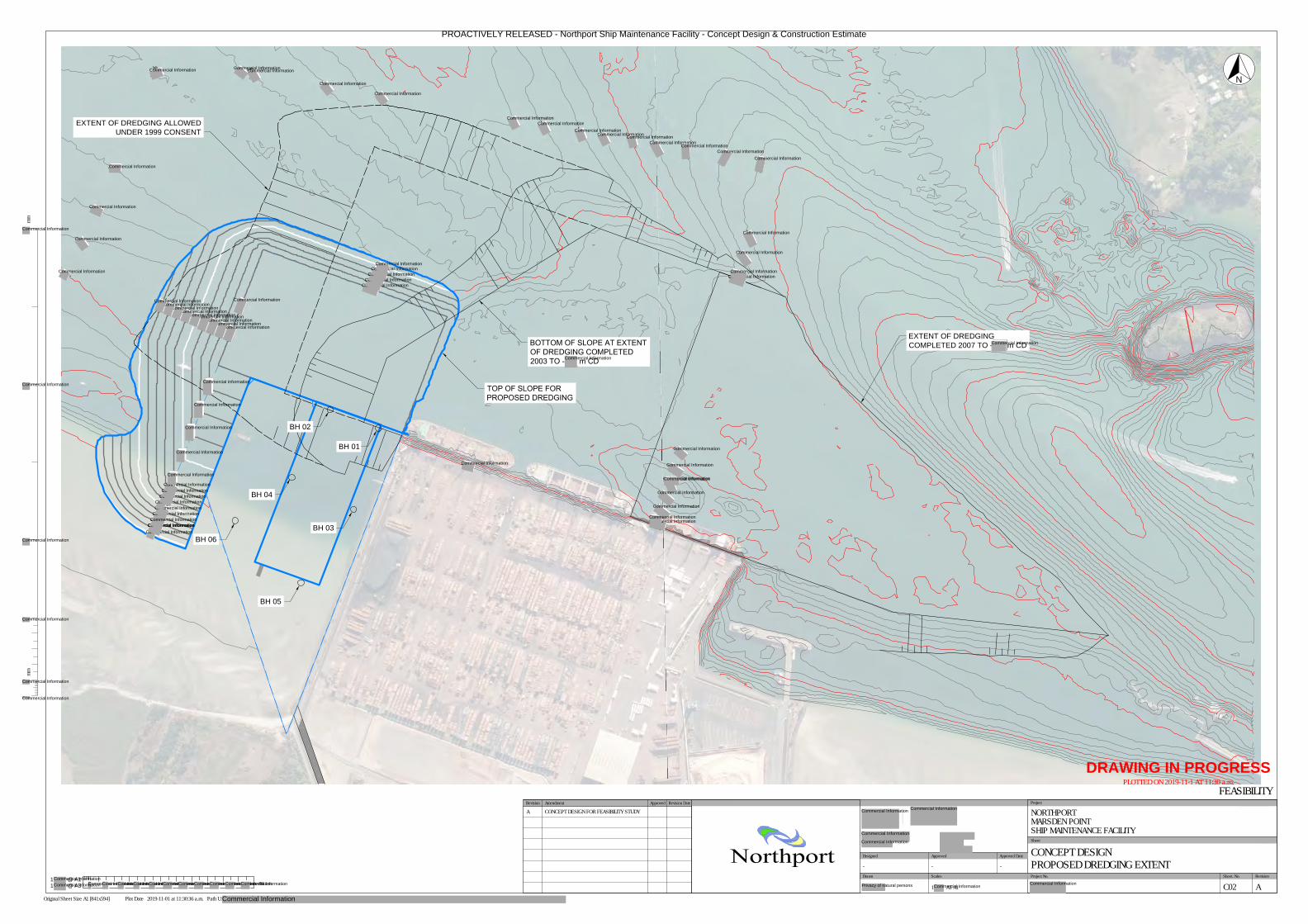
-
-
-
-
-
-
-
-
BH 05
BH 06
BH 04
BH 02
BH 01
BH 03
EXTENT OF DREDGING ALLOWED
UNDER 1999 CONSENT
EXTENT OF DREDGING
COMPLETED 2007 TO - m CD
BOTTOM OF SLOPE AT EXTENT
OF DREDGING COMPLETED
2003 TO .0m CD
TOP OF SLOPE FOR
PROPOSED DREDGING
mmmm
Scales Project No. Sheet. No.
Project
Sheet
Revision
Original Sheet Size A1 [841x594] Plot Date 2019-11-01 at 11:30:36 a.m. Path U:\
Drawn
Approved Approved Date
DRAWING IN PROGRESS
PLOTTED ON 2019-11-1 AT 11:30 a.m.
Northport
NORTHPORTMARSDEN POINTSHIP MAINTENANCE FACILITY
CONCEPT DESIGNPROPOSED DREDGING EXTENT
FEASIBILITY
C02 A
- - -
1: AT A1
Designed
1
m
@ A1
@ A31
N
Approved Revision DateRevision Amendment
A CONCEPT DESIGN FOR FEASIBILITY STUDY
PROACTIVELY RELEASED - Northport Ship Maintenance Facility - Concept Design & Construction Estimate
Commercial Information
Commercial InformationCommercial Information
Commercial InformationCommercial Information
Commercial InformationCommercial Information
Commercial Information
Commercial Information
Commercial Information
Commercial InformationCommercial Information
Commercial Information
Commercial Information
Commercial Information
Commercial Information
Commercial InformationCommercial Information
Commercial Information
Commercial Information
Commercial InformationCommercial Information
Commercial Information
Commercial InformationCommercial InformationCommercial Information
Commercial InformationCommercial Information
Commercial InformationCommercial Information
Commercial InformationCommercial InformationCommercial Information
Commercial Information
Commercial Information
Commercial Information
Commercial Information
Commercial Information
Commercial Information
Commercial Information
Commercial Information
Commercial Information
Commercial Information
Commercial Information
Commercial Information
Commercial InformationCommercial Information
Commercial Information
Commercial InformationCommercial Information
Commercial InformationCommercial InformationCommercial Information
Commercial InformationCommercial Information
Commercial InformationCommercial Information Commercial Information
Commercial InformationCommercial Information
Commercial InformationCommercial Information
Commercial Information
Commercial Information
Commercial Information
Commercial Information
Commercial Information
Commercial Information
Commercial Information
Commercial Information
Commercial InformationCommercial InformationCommercial InformationCommercial InformationCommercial InformationCommercial InformationCommercial InformationCommercial InformationCommercial InformationCommercial InformationCommercial Information
Commercial Information
Commercial InformationCommercial Information
Commercial Information
Commercial Information
Privacy of natural persons Commercial InformationCommercial Information
Commercial InformationCommercial Information
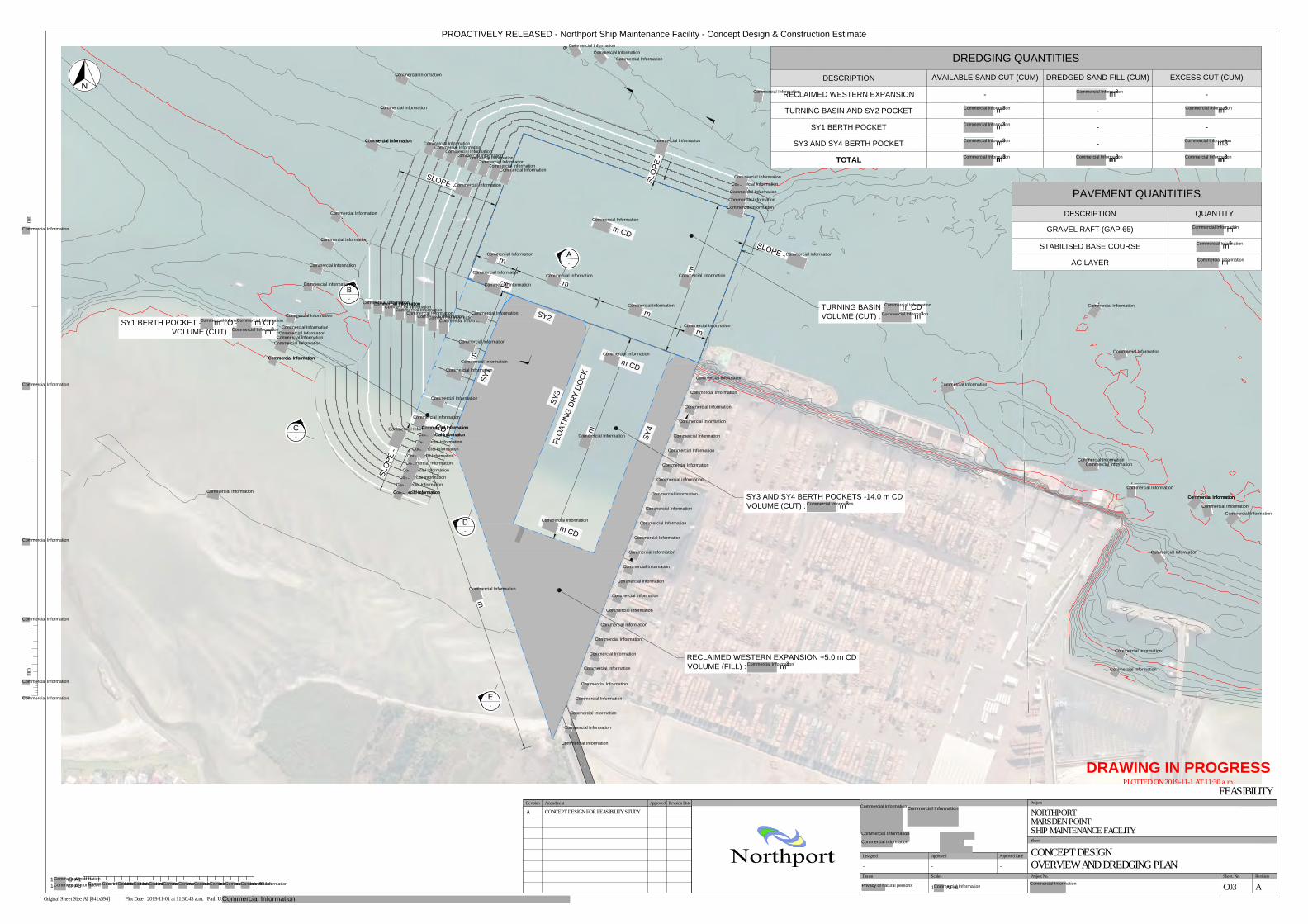
E
-
D
-
B
-
C
-
A
-
5
1
9
m
m
m
m
m
m
m
S
L
O
P
E
-
S
L
O
P
E
S
L
O
P
E
-
S
L
O
P
E
TURNING BASIN - m CD
VOLUME (CUT) : m
3
SY3 AND SY4 BERTH POCKETS -14.0 m CD
VOLUME (CUT) : m
3
SY1 BERTH POCKET - m TO - m CD
VOLUME (CUT) : m
3
RECLAIMED WESTERN EXPANSION +5.0 m CD
VOLUME (FILL) : m
3
C
D
C
D
m
C
D
m
C
D
m
C
D
S
Y
1
S
Y
3
S
Y
4
F
L
O
A
T
I
N
G
D
R
Y
D
O
C
K
S
Y
2
m
-
-
-
-
-
-
-
-
-10.0
-
-
-14.00
-
1
3
.0
0
.0
-
1
1
.
0
0
-
9
.0
0
-9.00
-
-8.00
-
7
.
0
0
-7.00
-
mmmm
Scales Project No. Sheet. No.
Project
Sheet
Revision
Original Sheet Size A1 [841x594] Plot Date 2019-11-01 at 11:30:43 a.m. Path U:\
Drawn
Approved Approved Date
DRAWING IN PROGRESS
PLOTTED ON 2019-11-1 AT 11:30 a.m.
Northport
NORTHPORTMARSDEN POINTSHIP MAINTENANCE FACILITY
CONCEPT DESIGNOVERVIEW AND DREDGING PLAN
FEASIBILITY
C03 A
- - -
1: AT A1
Designed
1
m
@ A1
@ A31
DREDGING QUANTITIES
DESCRIPTION
AVAILABLE SAND CUT (CUM) DREDGED SAND FILL (CUM) EXCESS CUT (CUM)
RECLAIMED WESTERN EXPANSION - m
3
-
TURNING BASIN AND SY2 POCKET m
3
- m
3
SY1 BERTH POCKET m
3
- -
SY3 AND SY4 BERTH POCKET m
3
- m3
TOTAL m
3
m
3
m
3
PAVEMENT QUANTITIES
DESCRIPTION QUANTITY
GRAVEL RAFT (GAP 65) m
3
STABILISED BASE COURSE m
3
AC LAYER m
3
N
Approved Revision DateRevision Amendment
A CONCEPT DESIGN FOR FEASIBILITY STUDY
PROACTIVELY RELEASED - Northport Ship Maintenance Facility - Concept Design & Construction Estimate
Commercial Information
Commercial Information
Commercial InformationCommercial Information
Commercial Information
Commercial Information
Commercial Information
Commercial Information
Commercial Information
Commercial InformationCommercial Information
Commercial InformationCommercial Information
Commercial Information
Commercial InformationCommercial Information
Commercial Information
Commercial Information
Commercial InformationCommercial InformationCommercial InformationCommercial Information
Commercial InformationCommercial Information
Commercial InformationCommercial InformationCommercial Information
Commercial InformationCommercial Information
Commercial InformationCommercial Information
Commercial Information
Commercial Information
Commercial Information
Commercial Information
Commercial Information
Commercial Information
Commercial Information
Commercial Information
Commercial Information
Commercial Information
Commercial Information
Commercial Information
Commercial Information
Commercial Information
Commercial Information
Commercial Information
Commercial Information
Commercial Information
Commercial Information
Commercial Information
Commercial Information
Commercial Information
Commercial Information
Commercial InformationCommercial Information
Commercial Information
Commercial Information
Commercial Information
Commercial Information
Commercial Information
Commercial Information
Commercial Information
Commercial InformationCommercial Information
Commercial Information
Commercial Information
Commercial Information
Commercial Information
Commercial InformationCommercial Information
Commercial InformationCommercial Information
Commercial Information
Commercial Information
Commercial Information
Commercial Information
Commercial Information
Commercial InformationCommercial Information
Commercial Information
Commercial Information
Commercial Information
Commercial Information
Commercial Information Commercial Information
Commercial Information
Commercial Information
Commercial Information
Commercial Information
Commercial Information
Commercial Information
Commercial Information
Commercial Information
Commercial Information
Commercial Information
Commercial Information
Commercial Information
Commercial InformationCommercial Information
Commercial Information
Commercial Information
Commercial Information
Commercial Information
Commercial Information
Commercial Information
Commercial Information
Commercial Information
Commercial Information
Commercial Information
Commercial Information
Commercial Information
Commercial Information
Commercial Information
Commercial Information
Commercial Information
Commercial Information
Commercial Information
Commercial Information
Commercial Information
Commercial Information
Commercial Information
Commercial Information
Commercial Information
Commercial Information
Commercial Information
Commercial Information
Commercial Information
Commercial Information
Commercial Information
Commercial Information
Commercial Information
Commercial Information
Commercial Information
Commercial InformationCommercial InformationCommercial InformationCommercial InformationCommercial InformationCommercial InformationCommercial InformationCommercial InformationCommercial InformationCommercial InformationCommercial Information
Commercial Information
Commercial Information
Commercial Information
Commercial Information
Commercial Information
Commercial Information
Commercial Information
Commercial InformationCommercial Information
Commercial Information
Commercial Information
Privacy of natural persons Commercial Information
Commercial Information
Commercial Information
Commercial InformationCommercial Information
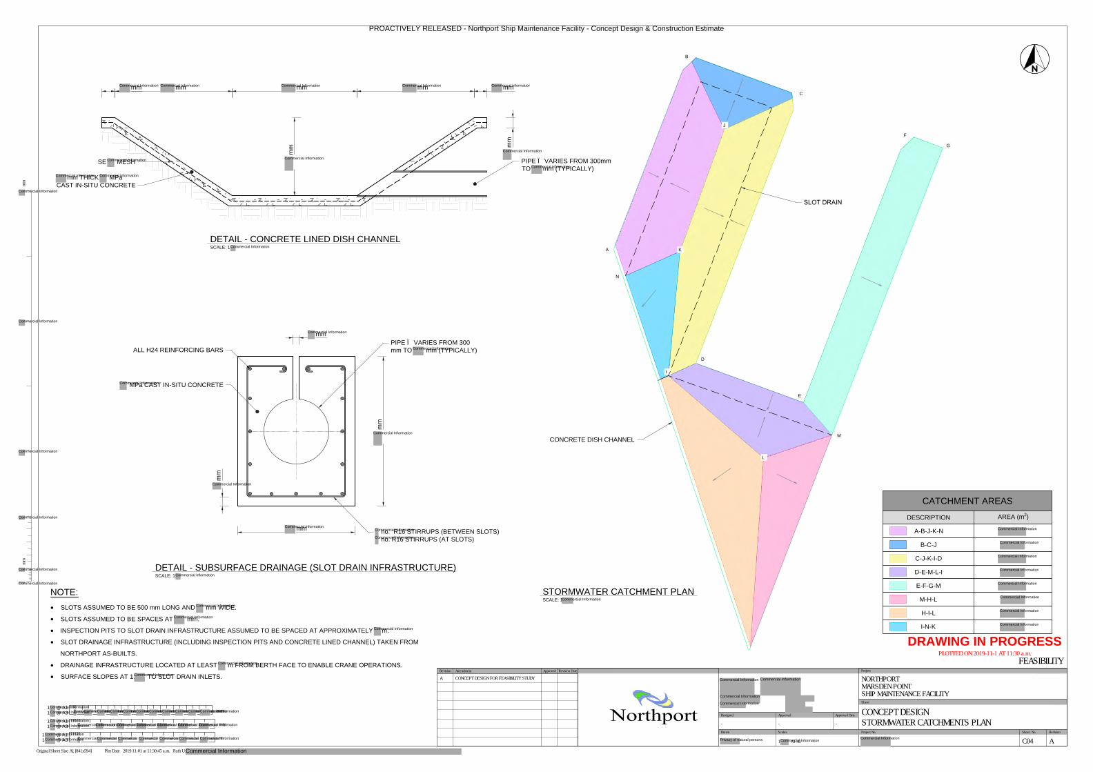
A
B
C
D
E
F
G
M
I
N
K
J
L
SLOT DRAIN
CONCRETE DISH CHANNEL
SCALE: 1
STORMWATER CATCHMENT PLAN
SE MESH
mm THICK MPa
CAST IN-SITU CONCRETE
mm mm mm mm mm
mm
PIPE Ø VARIES FROM 300mm
TO mm (TYPICALLY)
mm
SCALE: 1:
DETAIL - CONCRETE LINED DISH CHANNEL
mm
mm
mm
mm
no. R16 STIRRUPS (BETWEEN SLOTS)
no. R16 STIRRUPS (AT SLOTS)
PIPE Ø VARIES FROM 300
mm TO mm (TYPICALLY)ALL H24 REINFORCING BARS
MPa CAST IN-SITU CONCRETE
SCALE: 1:
DETAIL - SUBSURFACE DRAINAGE (SLOT DRAIN INFRASTRUCTURE)
CATCHMENT AREAS
DESCRIPTION
AREA (m
2
)
A-B-J-K-N
B-C-J
C-J-K-I-D
D-E-M-L-I
E-F-G-M
M-H-L
H-I-L
I-N-K
m
@ A11
@ A31
mmmm
Scales Project No. Sheet. No.
Project
Sheet
Revision
Original Sheet Size A1 [841x594] Plot Date 2019-11-01 at 11:30:45 a.m. Path U:\
Drawn
Approved Approved Date
DRAWING IN PROGRESS
PLOTTED ON 2019-11-1 AT 11:30 a.m.
Northport
NORTHPORTMARSDEN POINTSHIP MAINTENANCE FACILITY
CONCEPT DESIGNSTORMWATER CATCHMENTS PLAN
FEASIBILITY
C04 A
- - -
1: AT A1
Designed
1:
mm
@ A1
@ A31:
1:
mm
@ A1
@ A31:
NOTE:
· SLOTS ASSUMED TO BE 500 mm LONG AND mm WIDE.
· SLOTS ASSUMED TO BE SPACES AT mm.
· INSPECTION PITS TO SLOT DRAIN INFRASTRUCTURE ASSUMED TO BE SPACED AT APPROXIMATELY m.
· SLOT DRAINAGE INFRASTRUCTURE (INCLUDING INSPECTION PITS AND CONCRETE LINED CHANNEL) TAKEN FROM
NORTHPORT AS-BUILTS.
· DRAINAGE INFRASTRUCTURE LOCATED AT LEAST m FROM BERTH FACE TO ENABLE CRANE OPERATIONS.
· SURFACE SLOPES AT 1: TO SLOT DRAIN INLETS.
Approved Revision DateRevision Amendment
A CONCEPT DESIGN FOR FEASIBILITY STUDY
PROACTIVELY RELEASED - Northport Ship Maintenance Facility - Concept Design & Construction Estimate
Commercial Information Commercial Information Commercial Information Commercial Information Commercial Information
Commercial Information
Commercial Information
Commercial Information
Commercial Information Commercial Information
Commercial Information
Commercial Information
Commercial Information
Commercial Information
Commercial Information
Commercial Information
Commercial Information
Commercial Information
Commercial Information
Commercial Information
Commercial InformationCommercial InformationCommercial InformationCommercial InformationCommercial InformationCommercial InformationCommercial InformationCommercial InformationCommercial InformationCommercial InformationCommercial Information
Commercial InformationCommercial InformationCommercial InformationCommercial InformationCommercial InformationCommercial InformationCommercial Information
Commercial InformationCommercial InformationCommercial InformationCommercial InformationCommercial InformationCommercial InformationCommercial Information
Commercial Information
Commercial Information
Commercial Information
Commercial Information
Commercial Information
Commercial Information
Commercial Information
Commercial Information
Commercial Information
Commercial Information
Commercial Information
Commercial Information
Commercial Information
Commercial Information
Commercial Information
Commercial Information Commercial Information
Commercial Information
Commercial Information
Privacy of natural persons Commercial Information
Commercial Information
Commercial Information
Commercial Information
Commercial Information
Commercial Information
Commercial Information
Commercial Information
Commercial InformationCommercial Information
Commercial InformationCommercial Information
Commercial InformationCommercial Information Commercial Information
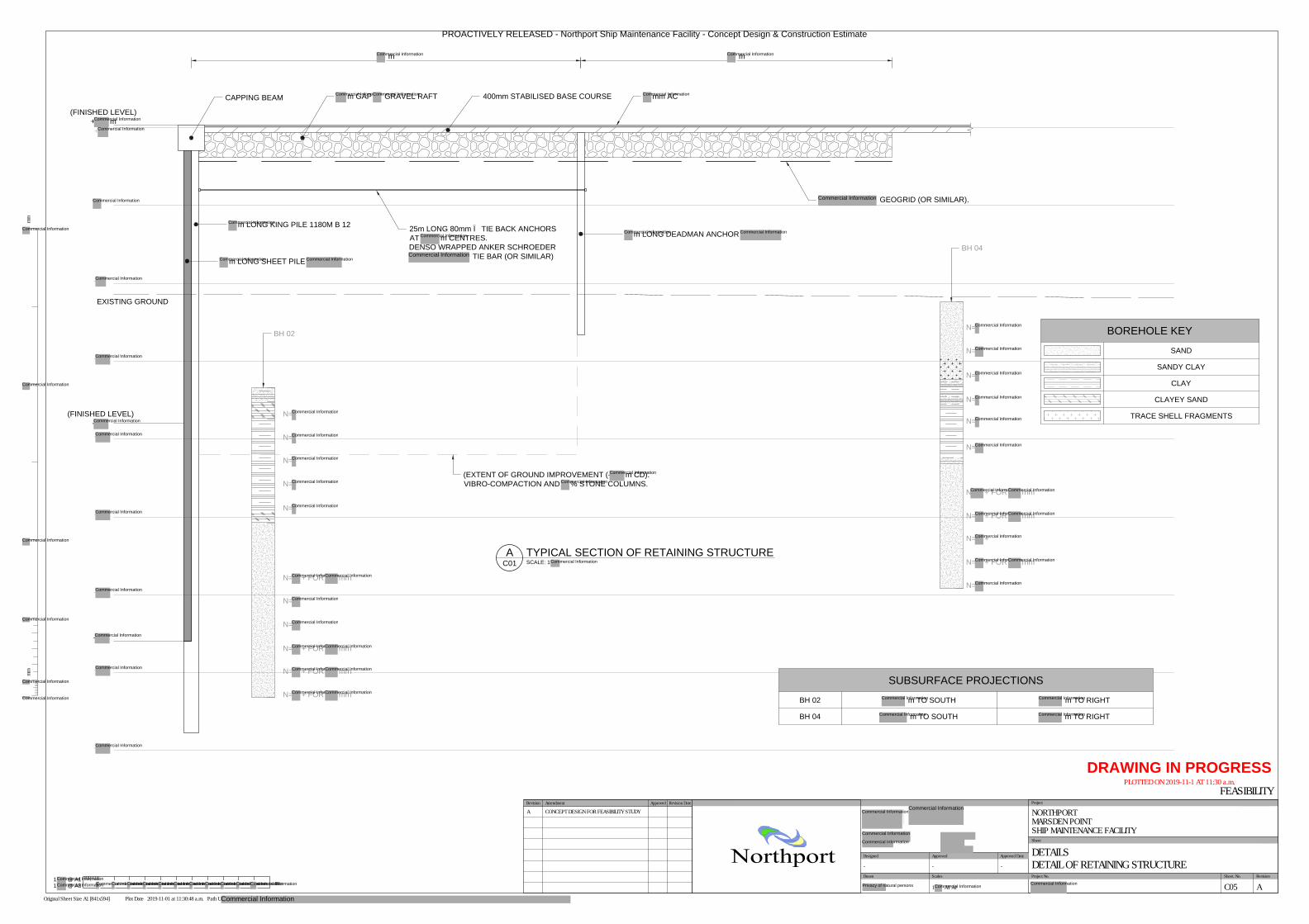
SCALE: 1
TYPICAL SECTION OF RETAINING STRUCTUREA
C01
N=
N=
N=
N=
N=
N=
N=
N= + FOR mm
N= + FOR mm
N= + FOR mm
N= + FOR mm
N=
N=
N=
N=
N=
N=
N + FOR mm
N= + FOR mm
N= +
N= + FOR mm
N=
-
-
-
-
-
-
-
+
EXISTING GROUND
(FINISHED LEVEL)
-
(EXTENT OF GROUND IMPROVEMENT (- m CD).
VIBRO-COMPACTION AND % STONE COLUMNS.
25m LONG 80mm Ø TIE BACK ANCHORS
AT m CENTRES.
DENSO WRAPPED ANKER SCHROEDER
TIE BAR (OR SIMILAR)
CAPPING BEAM
m GAP GRAVEL RAFT
m LONG DEADMAN ANCHOR
m LONG KING PILE 1180M B 12
m m
400mm STABILISED BASE COURSE mm AC
BH 02
BH 04
-
m LONG SHEET PILE
GEOGRID (OR SIMILAR).
(FINISHED LEVEL)
+ m
1:
m
@ A1
@ A31:
mmmm
Scales Project No. Sheet. No.
Project
Sheet
Revision
Original Sheet Size A1 [841x594] Plot Date 2019-11-01 at 11:30:48 a.m. Path U:
Drawn
Approved Approved Date
DRAWING IN PROGRESS
PLOTTED ON 2019-11-1 AT 11:30 a.m.
Northport
NORTHPORTMARSDEN POINTSHIP MAINTENANCE FACILITY
DETAILSDETAIL OF RETAINING STRUCTURE
FEASIBILITY
C05 A
- - -
1: AT A1
Designed
SUBSURFACE PROJECTIONS
BH 02 m TO SOUTH m TO RIGHT
BH 04 m TO SOUTH m TO RIGHT
BOREHOLE KEY
SAND
SANDY CLAY
CLAY
CLAYEY SAND
TRACE SHELL FRAGMENTS
Approved Revision DateRevision Amendment
A CONCEPT DESIGN FOR FEASIBILITY STUDY
PROACTIVELY RELEASED - Northport Ship Maintenance Facility - Concept Design & Construction Estimate
Commercial Information Commercial Information
Commercial InformationCommercial Information Commercial Information
Commercial Information
Commercial Information
Commercial InformationCommercial Information
Commercial Information
Commercial Information
Commercial Information
Commercial Information
Commercial Information
Commercial Information
Commercial Information
Commercial Information
Commercial Information
Commercial Information
Commercial Information
Commercial Information
Commercial Information
Commercial Information
Commercial Information
Commercial Information
Commercial Information
Commercial InformationCommercial Information
Commercial Information
Commercial Information
Commercial InformationCommercial Information
Commercial InformationCommercial Information
Commercial InformationCommercial Information
Commercial Information
Commercial Information
Commercial Information
Commercial Information
Commercial Information
Commercial Information
Commercial Information
Commercial Information
Commercial Information
Commercial Information
Commercial Information
Commercial InformationCommercial Information
Commercial InformationCommercial Information
Commercial Information
Commercial InformationCommercial Information
Commercial Information
Commercial Information
Commercial Information
Commercial Information
Commercial Information
Commercial Information
Commercial Information
Commercial Information
Commercial Information
Commercial Information
Commercial Information
Commercial Information
Commercial InformationCommercial InformationCommercial InformationCommercial InformationCommercial InformationCommercial InformationCommercial InformationCommercial InformationCommercial InformationCommercial InformationCommercial Information
Commercial Information
Commercial InformationCommercial Information
Commercial Information
Commercial Information
Privacy of natural persons Commercial InformationCommercial InformationCommercial Information
Commercial Information
Commercial Information
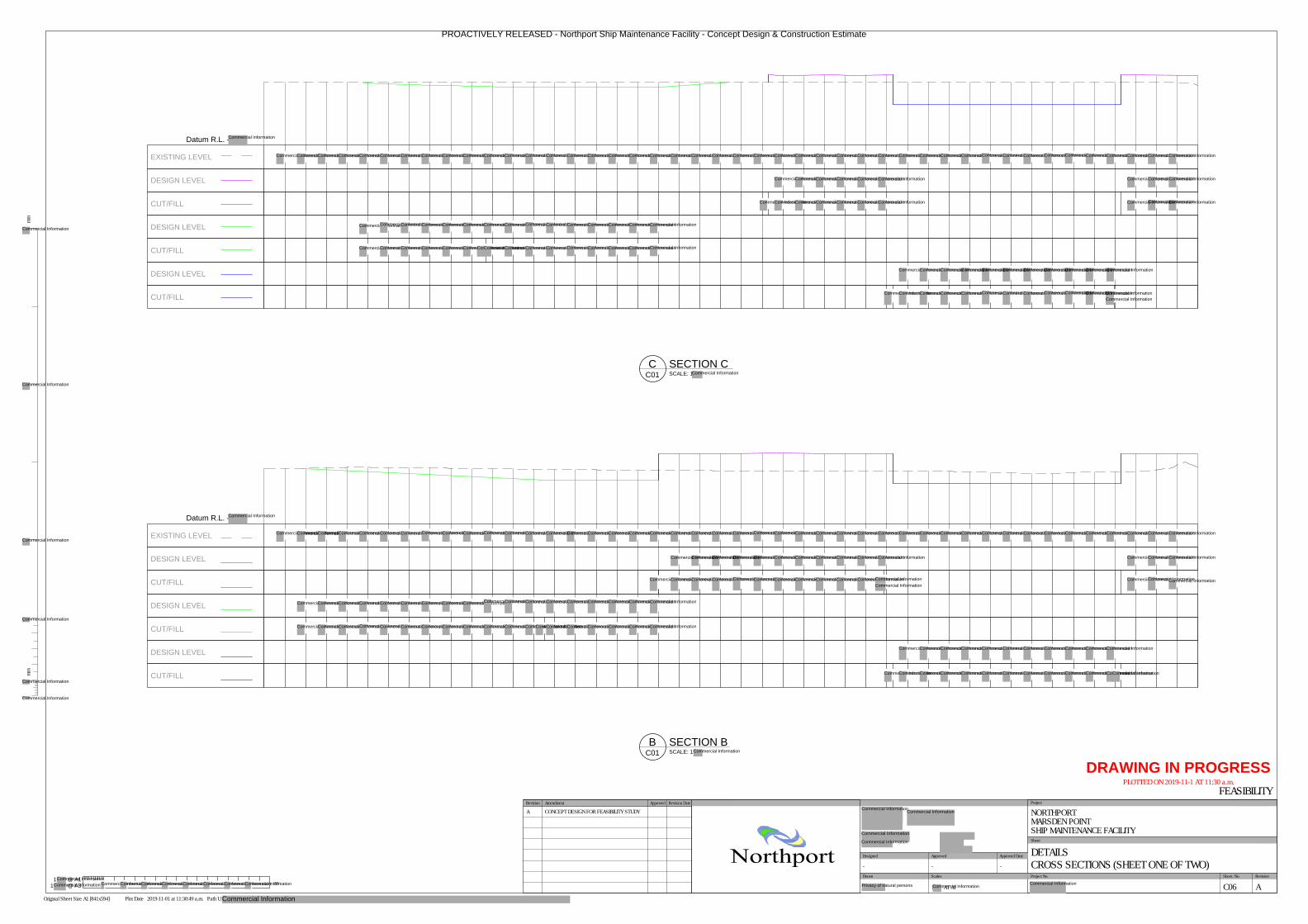
Datum R.L. -
EXISTING LEVEL
DESIGN LEVEL
CUT/FILL
DESIGN LEVEL
CUT/FILL
DESIGN LEVEL
CUT/FILL
Datum R.L. -
EXISTING LEVEL
DESIGN LEVEL
CUT/FILL
DESIGN LEVEL
CUT/FILL
DESIGN LEVEL
CUT/FILL
SCALE: 1
SECTION CC
C01
SCALE: 1:
SECTION BB
C01
-
- - - - - -
-
- - - - - -
- - - - - - - - - - -
-
- - -
-
- - - - - - - - - - -
- - - - -
-
- -
- -
- - -
- - - - - - -
-
- -
-
- - - - - - - - - - - -
-
- - - - - - - - - - - - - - - - - - - -
- - - - - - - - -
-
- - - - - - - -
- - -
-
- - - - - - - - - - - - - - -
- - - - - - - - - - -
- - - - - - - - - - - - -
@ A11:
m
@ A31
mmmm
Scales Project No. Sheet. No.
Project
Sheet
Revision
Original Sheet Size A1 [841x594] Plot Date 2019-11-01 at 11:30:49 a.m. Path U:\
Drawn
Approved Approved Date
DRAWING IN PROGRESS
PLOTTED ON 2019-11-1 AT 11:30 a.m.
Northport
NORTHPORTMARSDEN POINTSHIP MAINTENANCE FACILITY
DETAILSCROSS SECTIONS (SHEET ONE OF TWO)
FEASIBILITY
C06 A
- - -
1 AT A1
Designed
Approved Revision DateRevision Amendment
A CONCEPT DESIGN FOR FEASIBILITY STUDY
PROACTIVELY RELEASED - Northport Ship Maintenance Facility - Concept Design & Construction Estimate
Commercial Information
Commercial Information
Commercial Information
Commercial Information
Commercial Information
Commercial Information
Commercial Information
Commercial InformationCommercial InformationCommercial InformationCommercial InformationCommercial InformationCommercial InformationCommercial InformationCommercial InformationCommercial InformationCommercial InformationCommercial InformationCommercial InformationCommercial InformationCommercial InformationCommercial InformationCommercial InformationCommercial InformationCommercial InformationCommercial InformationCommercial InformationCommercial InformationCommercial InformationCommercial InformationCommercial InformationCommercial InformationCommercial InformationCommercial InformationCommercial Information
Commercial InformationCommercial InformationCommercial InformationCommercial Information
Commercial InformationCommercial InformationCommercial InformationCommercial InformationCommercial Information
Commercial InformationCommercial InformationCommercial InformationCommercial InformationCommercial InformationCommercial InformationCommercial InformationCommercial InformationCommercial InformationCommercial InformationCommercial InformationCommercial InformationCommercial InformationCommercial InformationCommercial Information
Commercial InformationCommercial InformationCommercial InformationCommercial InformationCommercial InformationCommercial InformationCommercial InformationCommercial InformationCommercial InformationCommercial InformationCommercial InformationCommercial InformationCommercial InformationCommercial InformationCommercial InformationCommercial Information
Commercial InformationCommercial Information
Commercial Information
Commercial InformationCommercial Information
Commercial Information
Commercial Information
Commercial Information
Commercial InformationCommercial InformationCommercial Information
Commercial Information
Commercial InformationCommercial InformationCommercial InformationCommercial InformationCommercial InformationCommercial InformationCommercial InformationCommercial InformationCommercial InformationCommercial InformationCommercial InformationCommercial InformationCommercial Information
Commercial InformationCommercial InformationCommercial Information
Commercial InformationCommercial InformationCommercial Information
Commercial Information
Commercial InformationCommercial InformationCommercial Information
Commercial InformationCommercial InformationCommercial InformationCommercial InformationCommercial InformationCommercial InformationCommercial InformationCommercial Information
Commercial InformationCommercial InformationCommercial InformationCommercial InformationCommercial InformationCommercial InformationCommercial Information
Commercial Information
Commercial Information
Commercial InformationCommercial Information
Commercial Information
Commercial InformationCommercial Information
Commercial Information
Commercial InformationCommercial Information
Commercial Information
Commercial InformationCommercial Information
Commercial Information
Commercial InformationCommercial Information
Commercial Information
Commercial InformationCommercial Information
Commercial Information
Commercial InformationCommercial Information
Commercial Information
Commercial InformationCommercial Information
Commercial Information
Commercial InformationCommercial Information
Commercial Information
Commercial InformationCommercial Information
Commercial Information
Commercial InformationCommercial InformationCommercial InformationCommercial InformationCommercial InformationCommercial InformationCommercial InformationCommercial InformationCommercial InformationCommercial InformationCommercial InformationCommercial InformationCommercial InformationCommercial Information
Commercial InformationCommercial InformationCommercial InformationCommercial InformationCommercial Information
Commercial InformationCommercial InformationCommercial InformationCommercial InformationCommercial InformationCommercial Information
Commercial Information
Commercial InformationCommercial Information
Commercial InformationCommercial Information
Commercial InformationCommercial InformationCommercial Information
Commercial InformationCommercial Information
Commercial InformationCommercial Information
Commercial InformationCommercial Information
Commercial InformationCommercial Information
Commercial Information
Commercial Information
Commercial Information
Commercial InformationCommercial Information
Commercial Information
Commercial InformationCommercial Information
Commercial Information
Commercial InformationCommercial Information
Commercial Information
Commercial InformationCommercial Information
Commercial Information
Commercial InformationCommercial Information
Commercial Information
Commercial Information
Commercial InformationCommercial InformationCommercial InformationCommercial InformationCommercial InformationCommercial InformationCommercial InformationCommercial InformationCommercial InformationCommercial InformationCommercial InformationCommercial InformationCommercial InformationCommercial InformationCommercial Information
Commercial InformationCommercial InformationCommercial Information
Commercial InformationCommercial InformationCommercial Information
Commercial InformationCommercial InformationCommercial InformationCommercial InformationCommercial InformationCommercial InformationCommercial InformationCommercial InformationCommercial InformationCommercial InformationCommercial Information
Commercial InformationCommercial InformationCommercial InformationCommercial InformationCommercial InformationCommercial InformationCommercial InformationCommercial InformationCommercial InformationCommercial InformationCommercial InformationCommercial InformationCommercial Information
Commercial InformationCommercial Information Commercial InformationCommercial InformationCommercial InformationCommercial InformationCommercial InformationCommercial InformationCommercial InformationCommercial Information
Commercial Information
Commercial InformationCommercial Information
Commercial Information
Commercial Information
Privacy of natural persons Commercial InformationCommercial Information
Commercial Information
Commercial Information
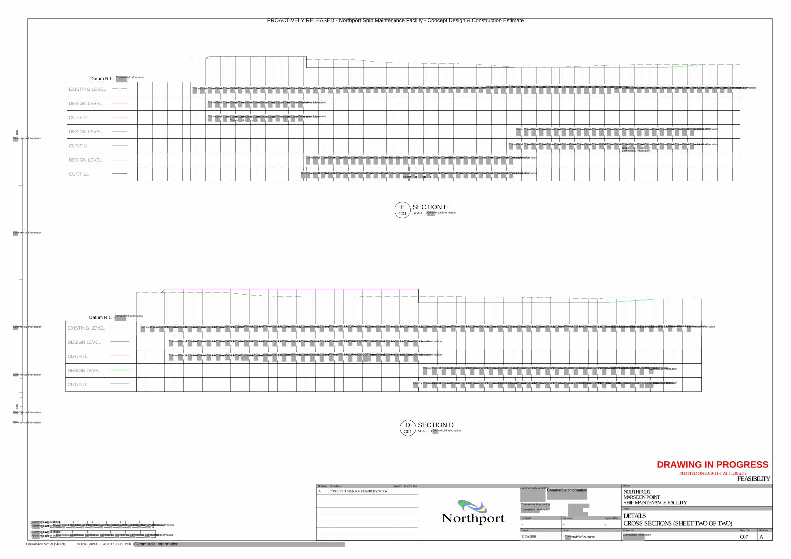
Datum R.L. -
EXISTING LEVEL
DESIGN LEVEL
CUT/FILL
DESIGN LEVEL
CUT/FILL
SCALE: 1:
SECTION DD
C01
- -
-
-
-
- - - - - -
- -
- - - -
-
- - - - - -
-
- - - - - - - - - - -
-
- - - - - - - - -
- - -
-
- - - - - - - - - - - - - - - - - - - -
- - - -
-
- - - - - - - - - - - - - - - - - -
-
-
-
- -
-
- -
- -
Datum R.L. -
EXISTING LEVEL
DESIGN LEVEL
CUT/FILL
DESIGN LEVEL
CUT/FILL
DESIGN LEVEL
CUT/FILL
SCALE: 1:
SECTION EE
C01
- - - - - - - - - -
-
- - - - - - - -
- - -
-
- - - - - - - - - - - - -
- - - - - - - - - - - - - - - -
- - - - - - - - - - - - - - - - - - - -
- - - -
- - - - - - - - - - - - - - - - - - - - - - - - - - - -- - - - - - - - - - - -
-
- - - - - - - - - - -
m
@ A11
@ A31
mmmm
Scales Project No. Sheet. No.
Project
Sheet
Revision
Original Sheet Size A1 [841x594] Plot Date 2019-11-01 at 11:30:51 a.m. Path U:\
Drawn
Approved Approved Date
DRAWING IN PROGRESS
PLOTTED ON 2019-11-1 AT 11:30 a.m.
Northport
NORTHPORTMARSDEN POINTSHIP MAINTENANCE FACILITY
DETAILSCROSS SECTIONS (SHEET TWO OF TWO)
FEASIBILITY
C07 A
- - -
T. CARTER 1: AND A:1250 AT A1
Designed
1
m
@ A1
@ A31
Approved Revision DateRevision Amendment
A CONCEPT DESIGN FOR FEASIBILITY STUDY
PROACTIVELY RELEASED - Northport Ship Maintenance Facility - Concept Design & Construction Estimate
Commercial Information
Commercial Information
Commercial InformationCommercial Information
Commercial InformationCommercial Information Commercial Information
Commercial Information
Commercial InformationCommercial InformationCommercial InformationCommercial InformationCommercial InformationCommercial InformationCommercial InformationCommercial InformationCommercial InformationCommercial InformationCommercial InformationCommercial InformationCommercial InformationCommercial InformationCommercial InformationCommercial InformationCommercial Information
Commercial InformationCommercial InformationCommercial InformationCommercial InformationCommercial InformationCommercial InformationCommercial InformationCommercial InformationCommercial InformationCommercial InformationCommercial InformationCommercial InformationCommercial Information
Commercial InformationCommercial InformationCommercial InformationCommercial InformationCommercial InformationCommercial InformationCommercial InformationCommercial InformationCommercial InformationCommercial InformationCommercial InformationCommercial InformationCommercial InformationCommercial Information
Commercial InformationCommercial InformationCommercial InformationCommercial InformationCommercial InformationCommercial InformationCommercial InformationCommercial InformationCommercial InformationCommercial InformationCommercial InformationCommercial InformationCommercial InformationCommercial InformationCommercial InformationCommercial InformationCommercial InformationCommercial InformationCommercial InformationCommercial InformationCommercial InformationCommercial InformationCommercial InformationCommercial InformationCommercial InformationCommercial InformationCommercial InformationCommercial InformationCommercial InformationCommercial InformationCommercial InformationCommercial InformationCommercial InformationCommercial InformationCommercial InformationCommercial InformationCommercial InformationCommercial InformationCommercial InformationCommercial InformationCommercial InformationCommercial InformationCommercial InformationCommercial InformationCommercial InformationCommercial InformationCommercial InformationCommercial InformationCommercial InformationCommercial InformationCommercial InformationCommercial InformationCommercial InformationCommercial InformationCommercial Information
Commercial InformationCommercial InformationCommercial InformationCommercial InformationCommercial InformationCommercial InformationCommercial InformationCommercial InformationCommercial InformationCommercial InformationCommercial InformationCommercial InformationCommercial InformationCommercial InformationCommercial InformationCommercial InformationCommercial InformationCommercial InformationCommercial InformationCommercial InformationCommercial InformationCommercial InformationCommercial InformationCommercial Information
Commercial InformationCommercial InformationCommercial InformationCommercial InformationCommercial InformationCommercial InformationCommercial InformationCommercial InformationCommercial InformationCommercial InformationCommercial InformationCommercial InformationCommercial InformationCommercial InformationCommercial InformationCommercial Information
Commercial InformationCommercial Information
Commercial InformationCommercial InformationCommercial InformationCommercial InformationCommercial InformationCommercial InformationCommercial InformationCommercial InformationCommercial Information
Commercial InformationCommercial InformationCommercial InformationCommercial InformationCommercial InformationCommercial InformationCommercial InformationCommercial InformationCommercial InformationCommercial InformationCommercial InformationCommercial InformationCommercial InformationCommercial InformationCommercial InformationCommercial InformationCommercial InformationCommercial InformationCommercial InformationCommercial InformationCommercial InformationCommercial InformationCommercial InformationCommercial InformationCommercial InformationCommercial InformationCommercial InformationCommercial Information
Commercial InformationCommercial InformationCommercial InformationCommercial InformationCommercial InformationCommercial InformationCommercial InformationCommercial InformationCommercial InformationCommercial InformationCommercial InformationCommercial InformationCommercial InformationCommercial InformationCommercial InformationCommercial InformationCommercial InformationCommercial InformationCommercial InformationCommercial InformationCommercial InformationCommercial InformationCommercial InformationCommercial InformationCommercial InformationCommercial InformationCommercial InformationCommercial InformationCommercial InformationCommercial InformationCommercial InformationCommercial Information
Commercial Information
Commercial Information
Commercial Information
Commercial Information
Commercial Information
Commercial Information
Commercial Information
Commercial InformationCommercial InformationCommercial InformationCommercial InformationCommercial InformationCommercial InformationCommercial InformationCommercial InformationCommercial InformationCommercial InformationCommercial InformationCommercial InformationCommercial InformationCommercial InformationCommercial InformationCommercial InformationCommercial InformationCommercial InformationCommercial InformationCommercial InformationCommercial InformationCommercial Information
Commercial InformationCommercial InformationCommercial InformationCommercial InformationCommercial InformationCommercial InformationCommercial InformationCommercial InformationCommercial InformationCommercial InformationCommercial InformationCommercial InformationCommercial InformationCommercial InformationCommercial InformationCommercial InformationCommercial InformationCommercial InformationCommercial Information
Commercial InformationCommercial InformationCommercial InformationCommercial InformationCommercial InformationCommercial InformationCommercial InformationCommercial InformationCommercial InformationCommercial InformationCommercial InformationCommercial InformationCommercial InformationCommercial InformationCommercial InformationCommercial InformationCommercial InformationCommercial InformationCommercial InformationCommercial Information
Commercial Information
Commercial Information
Commercial Information
Commercial InformationCommercial InformationCommercial InformationCommercial InformationCommercial InformationCommercial InformationCommercial InformationCommercial InformationCommercial InformationCommercial InformationCommercial InformationCommercial InformationCommercial InformationCommercial InformationCommercial InformationCommercial InformationCommercial InformationCommercial InformationCommercial InformationCommercial InformationCommercial InformationCommercial InformationCommercial InformationCommercial InformationCommercial Information
Commercial InformationCommercial InformationCommercial InformationCommercial InformationCommercial InformationCommercial InformationCommercial Information
Commercial InformationCommercial InformationCommercial InformationCommercial InformationCommercial InformationCommercial InformationCommercial InformationCommercial Information
Commercial Information
Commercial InformationCommercial Information
Commercial InformationCommercial Information
Commercial InformationCommercial InformationCommercial Information
Commercial InformationCommercial InformationCommercial InformationCommercial InformationCommercial InformationCommercial InformationCommercial InformationCommercial InformationCommercial InformationCommercial InformationCommercial InformationCommercial InformationCommercial InformationCommercial InformationCommercial Information
Commercial InformationCommercial InformationCommercial InformationCommercial InformationCommercial InformationCommercial InformationCommercial InformationCommercial InformationCommercial InformationCommercial InformationCommercial InformationCommercial InformationCommercial InformationCommercial InformationCommercial InformationCommercial InformationCommercial InformationCommercial InformationCommercial InformationCommercial Information
Commercial InformationCommercial Information
Commercial Information
Commercial Information
Commercial InformationCommercial InformationCommercial Information
Commercial InformationCommercial InformationCommercial InformationCommercial Information
Commercial InformationCommercial InformationCommercial InformationCommercial InformationCommercial InformationCommercial InformationCommercial InformationCommercial InformationCommercial InformationCommercial InformationCommercial Information
Commercial InformationCommercial Information
Commercial Information
Commercial Information
Commercial Information
Commercial Information
Commercial InformationCommercial InformationCommercial InformationCommercial InformationCommercial InformationCommercial InformationCommercial InformationCommercial InformationCommercial InformationCommercial InformationCommercial Information
Commercial InformationCommercial InformationCommercial InformationCommercial InformationCommercial InformationCommercial InformationCommercial Information
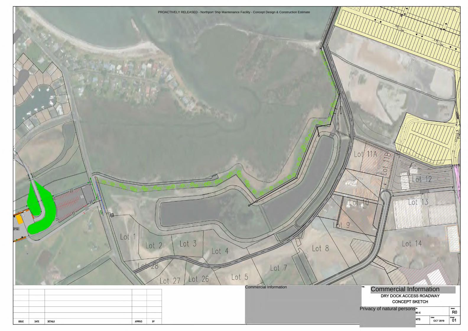
PROACTIVELY RELEASED - Northport Ship Maintenance Facility - Concept Design & Construction Estimate
Commercial Information
Privacy of natural persons
Commercial Information
Lot 1 Lot 2
Lot 4 Lot 3 Lot 8
Lot 7 Lot 26 Lot 5
.. ,
ISSUE DATE DETAILS APPRVD BY
I L -- - __ _J
Lot 14 ~
DRY DOCK ACCESS ROADWAY
CONCEPT SKETCH
No
60-X
NTS OCT 2019
Issue:
RO Shoot
01
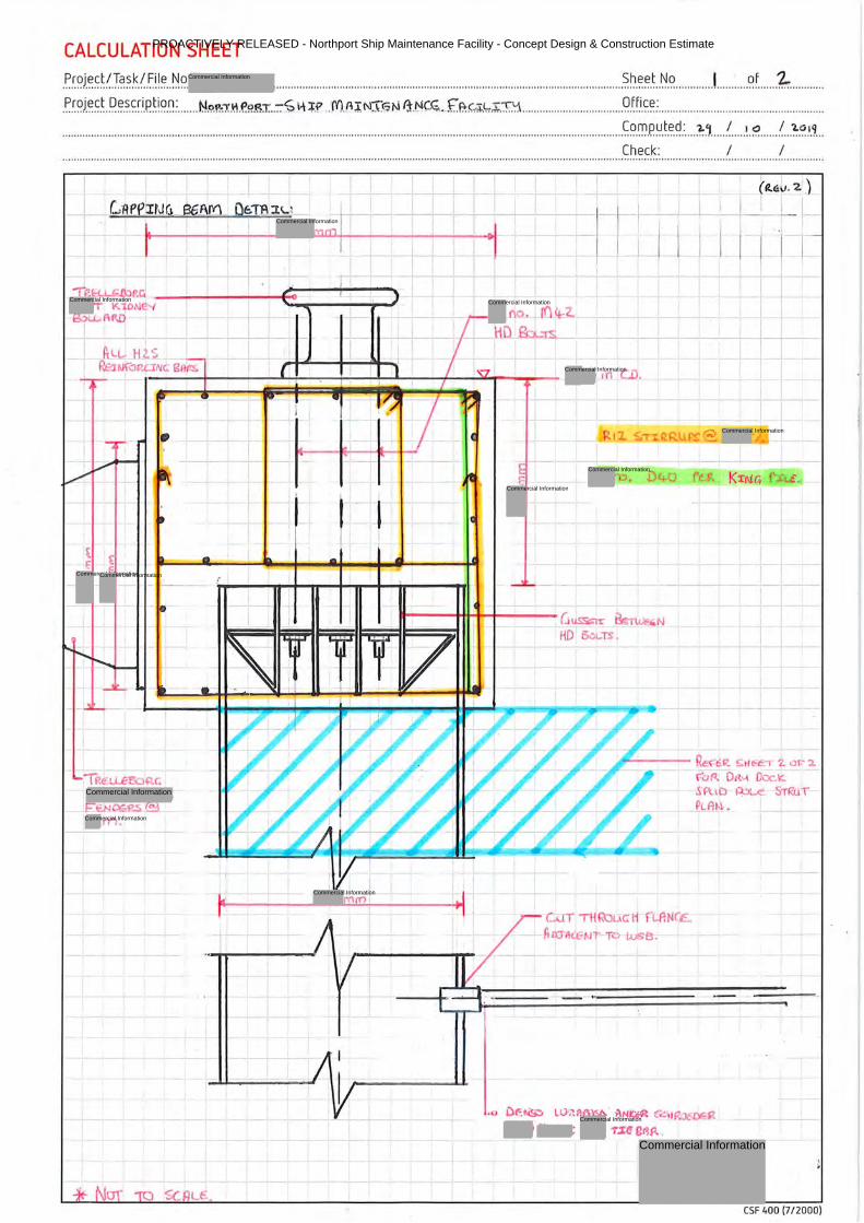
CALCULATION SHEET
_P,_r~J.~~_t!_Ta,~_k_(_F,il ~--~-~-: .......... .. .... ..... ...... ... ... ...... .... .. .. .... ... ... .. ..... .. .................................... ...... .. .. ...... S.~.~~-t .. N..°. ............. ! ........... °.f. .... .. 4: ........... . . P.r.~J.~~-t . .O.~.s-~r_ip_ti~-~: ..... .. NP.!1:-:-n\.f'-<?.~I..::-£ 1~ ~.f. _.f()_A I NT~ N IJ~~.f.f.+:(,,;_t,,~.':t;.'::\ .. .. .. .... ...... .. ... ....... ..... .. 9.ff_i_c_~.: .. ...... ....... ....... .................................. .
....... .. ....... ... ..... .. ... ...... ... ... .. ......... .. ......................................... ... .................................................................... ............................ \=~.~.P.~.t-~-~.:. ... :2:l .... ! .... .'.~ ... ... ! ... l:.°..1.1 .. . Check: I I .... ........ .. ..... ................................. ...... ... .. .... ........ .. ... .. ..... .. ... ... ... .... ..... ..... ... ........ .... .... ...... .. ..... ... .... .... ... .... .. .... .... .. .. .. ....... .. .. .... .... ... .... ..... .. .. .. ... ... .. ............. , ........................ . .
j I I
l I I I_I i
(R..c.u. 2 1.)
I I
-+
~I- t ,----+------1......;.-----1-~i---J.___-....... _ ~ - ........ - - ,n en.
1R€~~r.
£:E.N06f'~ @ .rn .
.I I
ru . D4o rr Kri\lc.
Uu.SSG:Tr ~ - N HD 5.:il..TS •
.---- Re: e:.lt S tf C'.e, '2. or 1
(..:UT Ti t uc:H r LP.NCE. fillJ'A~NT T'-' Lu5B.
(.'u P.. - Ott'-\ Doc.le .SPuD ~ STRi.lT Pt. At-I. .
,o i)t<:~ ll)·;:1 ~ · i\N~ !"..;',I F: QF.$'.
-n~ E)r{p.
CSF 400 (7 / 2000)
PROACTIVELY RELEASED - Northport Ship Maintenance Facility - Concept Design & Construction Estimate
Commercial Information
Commercial Information
Commercial Information
Commercial Information
Commercial Information
Commercial Information
Commercial Information
Commercial InformationCommercial Information
Commercial Information
Commercial Information
Commercial Information
Commercial Information
Commercial Information
Commercial Information
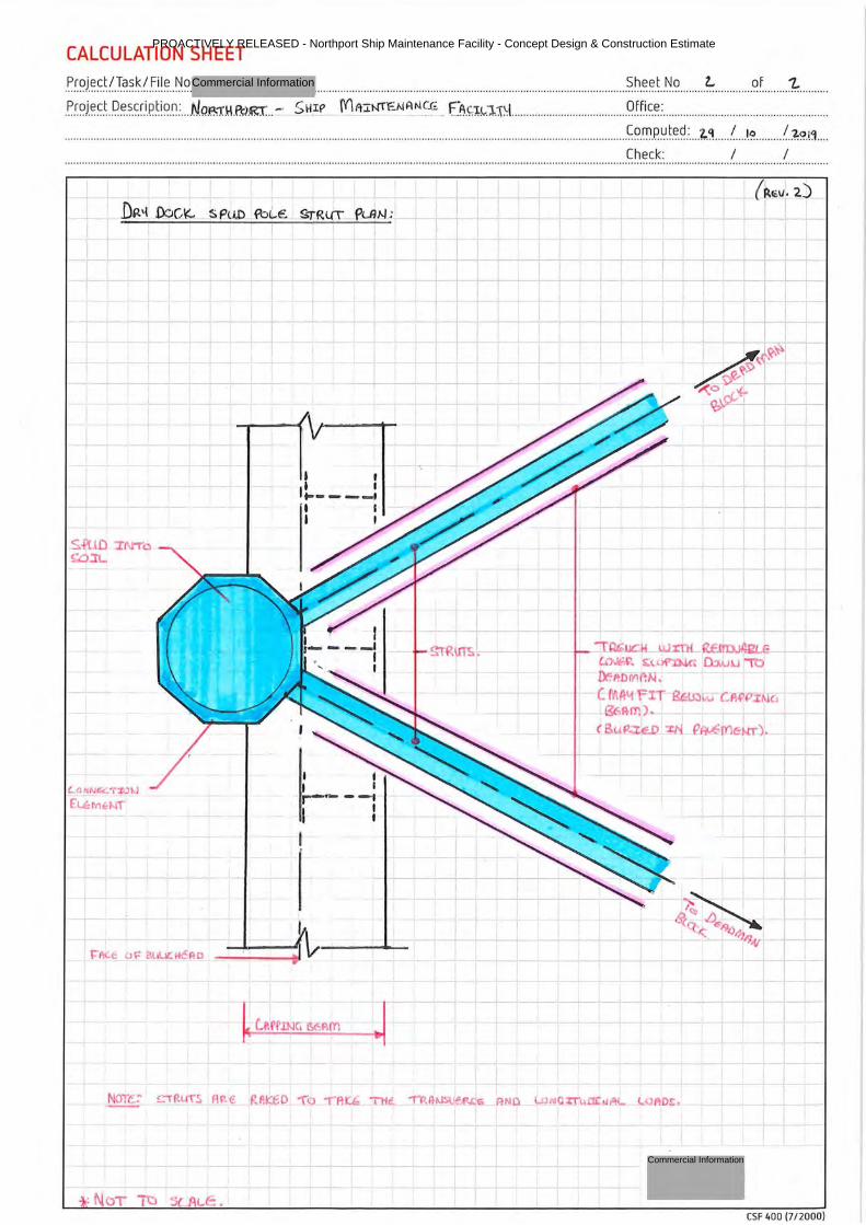
PROACTIVELY RELEASED - Northport Ship Maintenance Facility - Concept Design & Construction Estimate
Commercial Information
Commercial Information
CALCULATION SHEET Sheet No Z... of '1..
P.r.?J.~~.t.P.~.s-~ ~-i_p_ti?_~: .. .. N.o.,:1,,: \1 .&>.gr __ - SHif> Mr-r:r~NANCG fJ:\ . .'.t!..'lJ\l. ... ... .. .. ..... ..... ......... ......... . qtf.i_c_~_: ....................................... ...... ...... .... . .
..................................................... ... ......................... ...... .. .... .......... .................................... ... .... ........ .... .. ...... ... ................. .. ...... ~?.n.1.P.~.t.e.~.: ... . t.<\ .. .. . ! ... .l.? ......... !.?:~.tj ___ _
L.o NNC:C: , :f.J
E'~IVIH-!T'
: NOT TC S{ AL.C-: '
I t I I ,~ ___ _, I I I I
I i I I ~--t
I l I
T
-1
Check: I I
--+
,aGucM u..J..rrH. f(E.l'tOJ4ae C.0.Jf;r. ~, >i'DJ.C. [b.u LI it,
DF P. o 1Y1 AN-:-C lt'LAl.t FIT 8£:~ J C:A~ Ii\l(1
I 1=1
L
IY,Ptrn), C -
' B"e <'.D-"'l'i Pl'M'!l'l•n " -i +-----
I
l
CSF 400 (7 /2000)
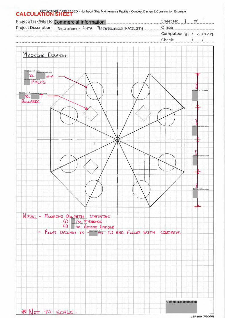
CALCULATION SHEET
.P. r.<?JE:?!::~(Tci?.~l.~!.1.~ .. ~.<?:. .. ........... .. .............. .. .. .... ... ....................... .. .... .... ~.~-~~-t .. ~.<? .... ; .... l. .......... <?.f. ....... .l. .. .... ..... .
. P.r.<?JE:?!::~ . .l?.~~-~.r!.P~!?.t1.: ........ N.QJ?,.:r.1:1~g:r._:..~ _wJf ___ fi\A-z~~N._G.N.C~- FI\Gl~"J.:-N .. ... ...... .... .. ...... . .C?.ft!.~~: ..................... .. ... .............. .... ... ..... ..
....... .. ..................... ...... ... .. ....... ... ... ... ... .................. ............. .. .......... .. ............. .... .... .. ............................................ .. .............. .... .. ~<?~.P..~.~~.9. : ... ~J .... / .. .t.9. ... /. .~9..L':1. Check: I I .. .. .......................................... .... ........... ...... .................. ... ... .......... ... .......................... ..... .. ...... ... .. ........................... ........ .. ................ ... .... .. .. ... .. .. ...... .. ... .................................
+--+--+-+--t--+--t- i
--- ...---- I---- --- - -I-- - --i--- r- - - . ----
·-f- -- --- - t--- - - --,----- - ~ +---;-+-----'-~
1- ---f- - -r-- -- f--1----- 1-- -4-l---+---1
- --i-- --- - - +----i--i ----- -- 1-t---
r~r---- · ---t--
--- -f-- -t----r- ---- -- - r-----;---;--1- --r-----1--+--t----------
,_ -- -f-
~ --- - ---t----- t----i----t---t-
- ->-- ---t-· ----t-- ;...--- ---- ------+-t---t - ---+-t----+ ---- ,-+.-----,-1
~-----t-- -!----- t- t- -- . --- - --- ----- r-- -r--- - _.___...____
----i---
CSF 400 (7/2000)
PROACTIVELY RELEASED - Northport Ship Maintenance Facility - Concept Design & Construction Estimate
Commercial Information
Commercial Information
Commercial InformationCommercial Information
Commercial Information
Commercial Information
Commercial Information
Commercial Information
Commercial Information
Commercial Information
Commercial Information
Commercial Information
Commercial Information
Commercial Information

Appendix B Proposed Concept - Estimate
PROACTIVELY RELEASED - Northport Ship Maintenance Facility - Concept Design & Construction Estimate
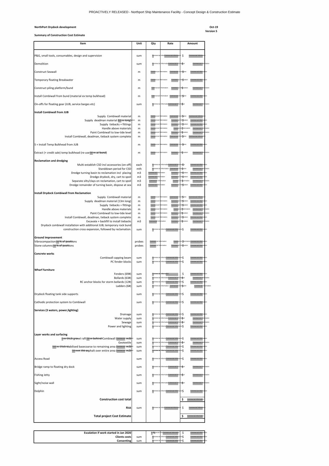
NorthPort Drydock development Oct-19
Version 5
Summary of Construction Cost Estimate
Item Unit Qty Rate Amount
P&G, small tools, consumables, design and supervision sum $
Demolition sum $
Construct Seawall m $
Temporary floating Breakwater m $
Construct piling platform/bund m $
Install Combiwall from bund (material ex temp bulkhead) m $
On-offs for floating gear (JUB, service barges etc) sum $
Install Combiwall from JUB
Supply Combiwall material m $
Supply deadman material ( m long) m $
Supply tiebacks + fittings m $
Handle above materials m $
Paint Combiwall to low-tide level m $
Install Combiwall, deadman, tieback system complete m $
S + Install Temp Bulkhead from JUB m $
Extract (+ credit sale) temp bulkhead (re-use m at bund) m $
Reclamation and dredging
Multi-establish CSD incl accessories (on-off) each $
Standdown period for CSD mth $
Dredge turning basin to reclamation incl placing m3 $
Dredge drydock, dry, cart to spoil m3 $
Separate silts/clays on reclamation, cart to spoil m3 $
Dredge remainder of turning basin, dispose at sea m3 $
Install Drydock Combiwall from Reclamation
Supply Combiwall material m $
Supply deadman material (13m long) m $
Supply tiebacks + fittings m $
Handle above materials m $
Paint Combiwall to low-tide level m $
Install Combiwall, deadman, tieback system complete m $
Excavate + backfill to install tiebacks m3 $
Drydock combiwall installation with additional JUB; temporary rock bund
construction cross expansion, followed by reclamation. sum $
Ground Improvement
Vibrocompaction % of positions probes $
Stone columns % of positions probes $
Concrete works
Combiwall capping beam sum $
PC fender blocks sum $
Wharf furniture
Fenders (69#) sum $
Bollards (63#) sum $
RC anchor blocks for storm bollards (12#) sum $
Ladders (6#) sum $
Drydock floating tank side supports sum $
Cathodic protection system to Combiwall sum $
Services (3 waters, power,lighting)
Drainage sum $
Water supply sum $
Sewage sum $
Power and lighting sum $
Layer works and surfacing
m thick gravel raft m behind Combiwall ( m3) sum $
Geotextile sum $
m thick stabilised basecoarse to remaining area ( m3) sum $
mm thk asphalt over entire area ( m2) sum $
Access Road sum $
Bridge ramp to floating dry dock sum $
Fishing Jetty sum $
Sight/noise wall sum $
Dolphin sum $
Construction cost total $
Risk sum $
Total project Cost Estimate $
Escalation if work started in Jan 2020 % $
Clients costs sum $
Consenting sum $
PROACTIVELY RELEASED - Northport Ship Maintenance Facility - Concept Design & Construction Estimate
Commercial Information
Commercial Information
Commercial Information
Commercial Information
Commercial Information
Commercial Information
Commercial Information
Commercial Information
Commercial Information
Commercial Information
Commercial Information
Commercial Information
Commercial Information
Commercial Information
Commercial Information
Commercial InformationCommercial Information
Commercial Information
Commercial Information
Commercial Information
Commercial Information
Commercial Information
Commercial Information
Commercial Information
Commercial Information
Commercial Information
Commercial Information
Commercial Information
Commercial Information
Commercial Information
Commercial Information
Commercial Information
Commercial Information
Commercial Information
Commercial Information
Commercial Information
Commercial Information
Commercial Information
Commercial Information
Commercial Information
Commercial Information
Commercial Information
Commercial Information
Commercial Information
Commercial Information
Commercial Information
Commercial Information
Commercial Information
Commercial Information
Commercial Information
Commercial InformationCommercial Information
Commercial Information Commercial Information Commercial Information
Commercial Information
Commercial InformationCommercial Information
Commercial Information
Commercial Information
Commercial Information
Commercial Information
Commercial Information
Commercial Information
Commercial Information
Commercial Information
Commercial Information
Commercial Information
Commercial Information
Commercial Information
Commercial Information
Commercial Information
Commercial Information
Commercial Information
Commercial Information
Commercial Information
Commercial Information
Commercial Information
Commercial Information
Commercial Information
Commercial Information
Commercial Information
Commercial Information
Commercial Information
Commercial Information
Commercial Information
Commercial Information
Commercial Information
Commercial Information
Commercial Information
Commercial Information
Commercial Information
Commercial Information
Commercial Information
Commercial Information
Commercial Information
Commercial Information
Commercial Information
Commercial Information
Commercial Information
Commercial Information
Commercial Information
Commercial Information
Commercial Information
Commercial Information
Commercial Information
Commercial Information
Commercial Information
Commercial Information
Commercial Information
Commercial Information
Commercial Information
Commercial Information
Commercial Information
Commercial Information
Commercial Information Commercial Information
Commercial Information
Commercial Information
Commercial Information
Commercial Information
Commercial Information
Commercial Information
Commercial Information
Commercial Information
Commercial Information
Commercial Information
Commercial Information
Commercial Information
Commercial Information
Commercial Information
Commercial Information
Commercial Information
Commercial Information
Commercial Information
Commercial Information
Commercial Information
Commercial Information
Commercial Information
Commercial Information
Commercial Information
Commercial Information
Commercial Information
Commercial Information
Commercial Information
Commercial Information
Commercial Information
Commercial Information
Commercial Information
Commercial Information
Commercial Information
Commercial Information
Commercial Information
Commercial Information
Commercial Information
Commercial Information
Commercial Information
Commercial Information
Commercial Information
Commercial Information
Commercial Information
Commercial Information
Commercial Information
Commercial Information
Commercial Information
Commercial Information
Commercial Information
Commercial Information
Commercial Information
Commercial Information
Commercial Information
Commercial Information
Commercial Information
Commercial InformationCommercial Information
Commercial Information
Commercial Information Commercial Information
Commercial Information
Commercial Information
Commercial Information
Commercial Information

PROACTIVELY RELEASED - Northport Ship Maintenance Facility - Concept Design & Construction Estimate
Commercial Information
N O R T H P O RT L T D
N O R T H P O RT W E S T E R N R E C LA MA TI ON O P TI O N – C O NC E PT D ES I G N S TA G E
P R E L I M I N A R Y G E O T E C H N I C A L R E P O R T
INITIA REF NOVEMBER 2019
PROACTIVELY RELEASED - Initia Preliminary Geotechnical Report
Commercial Information
November 2019 Initia Ref: Northport Western Reclamation Option– Concept Design Stage INITIA
Contents
1. Introduction .......................................................................................................................................................... 3
1.1 Project Overview ...................................................................................................................................... 3
1.2 Scope of Works ........................................................................................................................................ 3
2. Historical Geotechnical Testing ....................................................................................................................... 4
3. Geology ................................................................................................................................................................. 5
3.1 Geological Setting .................................................................................................................................... 5
4. Subsurface Investigations .................................................................................................................................. 6
4.1 General ....................................................................................................................................................... 6
4.2 Cone Penetration Testing (CPT) ............................................................................................................ 6
4.3 Rotary Cored Boreholes .......................................................................................................................... 7
4.4 Ground model ........................................................................................................................................... 7
5. Laboratory Testing .............................................................................................................................................. 9
5.1 Sampling ..................................................................................................................................................... 9
5.2 Laboratory Test Scheduling .................................................................................................................... 9
5.3 Laboratory Testing ................................................................................................................................... 9
5.4 Results ........................................................................................................................................................ 9
6. Geotechnical Considerations ..........................................................................................................................10
6.1 Seismic Assessment ...............................................................................................................................10
6.1.1 Site Subsoil Class .......................................................................................................................10
6.1.2 Liquefaction Potential ..............................................................................................................10
6.2 Consolidation Settlement .....................................................................................................................10
6.3 Reclamation Earthworks .......................................................................................................................10
7. Further works ....................................................................................................................................................11
8. Applicability ........................................................................................................................................................12
APPENDIX SUMMARY ............................................................................................................................................14
Appendix A: Figures ...................................................................................................................................
Appendix B: Borehole Logs and Core Photographs .............................................................................
Appendix C: Cone Penetration Test Results .........................................................................................
Appendix D: Geological Cross Sections ..................................................................................................
Appendix E: Geotechnical Laboratory Test Results .............................................................................
Appendix F: SPT Based Liquefaction Analysis ......................................................................................
Appendix G: Previous Geotechnical Testing and Reports ..................................................................
PROACTIVELY RELEASED - Initia Preliminary Geotechnical Report
Commercial Information
3
November 2019 Initia Ref: Northport Western Reclamation Option– Concept Design Stage INITIA
1. Introduction
1.1 Project Overview
Northport Limited has commenced the Concept Design of a proposed floating dry dock and land
reclamation area at their facility at Marsden Point, South of Whangarei. The new development is to be
located directly west of the existing Northport Wharf structure. The existing dock is located on the
south eastern edge of Whangarei Harbour, immediately north west of Marsden Point Oil Refinery. The
proposed development comprises the construction of a new dry dock to service and maintain ships.
We understand that the facility will service The Royal New Zealand Navy Ships and private vessels.
We also understand that Northport have brought together a team of consultants to undertake early
concept designs for the structure. Initia Limited (Initia) is providing the geotechnical data for these
designs.
Prior to the investigations commencing, the consultant team provided input to the scope of works.
Static Cone Penetration testing (CPT) was added to the original drilling programme in an attempt to
gain comprehensive strength data of the soils.
1.2 Scope of Works
The scope of works is outlined in our ‘Geotechnical Services for a Western Reclamation Option at
Northport, Northland,1’ which included:
• Desk study of previous geotechnical explorations;
• Drilling of deep ground investigations, comprising machine boreholes and CPTs to investigate
the subsurface conditions at the specific target areas;
• Preparation of drilling logs from the field investigations;
• Collection of soil samples and testing in an accredited laboratory;
• Preparation of this Geotechnical Report documenting the geotechnical conditions at the site
and the results of all field and laboratory investigations;
• Geotechnical laboratory testing to assess soil types.
We consider this phase of works to be suitable for concept design only. Further stages of specific
investigations will need to be carried out for developed and detailed design. The Investigations were
scoped for a set budget within a set timeframe due to equipment availability.
1 ‘Geotechnical Services for a Western Reclamation Option at Northport, Northland’ dated 10 September 2019,
prepared by Initia, addressed to for Northport Limited.
PROACTIVELY RELEASED - Initia Preliminary Geotechnical Report
Privacy of natural persons
Commercial Information
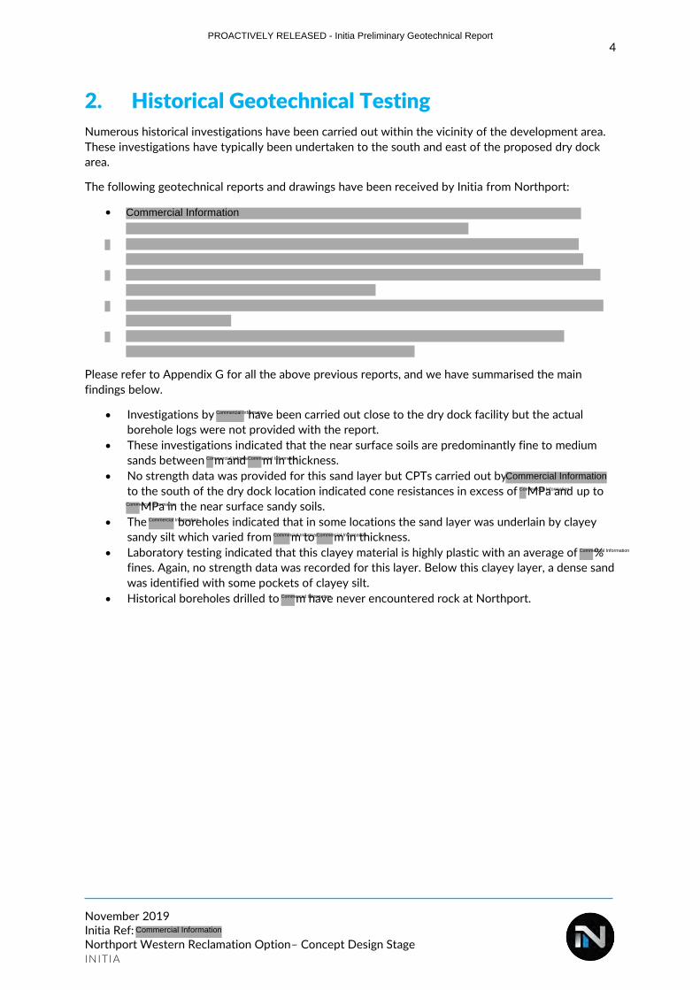
4
November 2019 Initia Ref: Northport Western Reclamation Option– Concept Design Stage INITIA
2. Historical Geotechnical Testing
Numerous historical investigations have been carried out within the vicinity of the development area.
These investigations have typically been undertaken to the south and east of the proposed dry dock
area.
The following geotechnical reports and drawings have been received by Initia from Northport:
•
Please refer to Appendix G for all the above previous reports, and we have summarised the main
findings below.
• Investigations by have been carried out close to the dry dock facility but the actual
borehole logs were not provided with the report.
• These investigations indicated that the near surface soils are predominantly fine to medium
sands between m and m in thickness.
• No strength data was provided for this sand layer but CPTs carried out by
to the south of the dry dock location indicated cone resistances in excess of MPa and up to
MPa in the near surface sandy soils.
• The boreholes indicated that in some locations the sand layer was underlain by clayey
sandy silt which varied from m to m in thickness.
• Laboratory testing indicated that this clayey material is highly plastic with an average of %
fines. Again, no strength data was recorded for this layer. Below this clayey layer, a dense sand
was identified with some pockets of clayey silt.
• Historical boreholes drilled to m have never encountered rock at Northport.
PROACTIVELY RELEASED - Initia Preliminary Geotechnical Report
Commercial Information
Commercial Information
Commercial InformationCommercial Information
Commercial Information
Commercial Information
Commercial Information
Commercial Information
Commercial InformationCommercial Information
Commercial Information
Commercial Information
Commercial Information
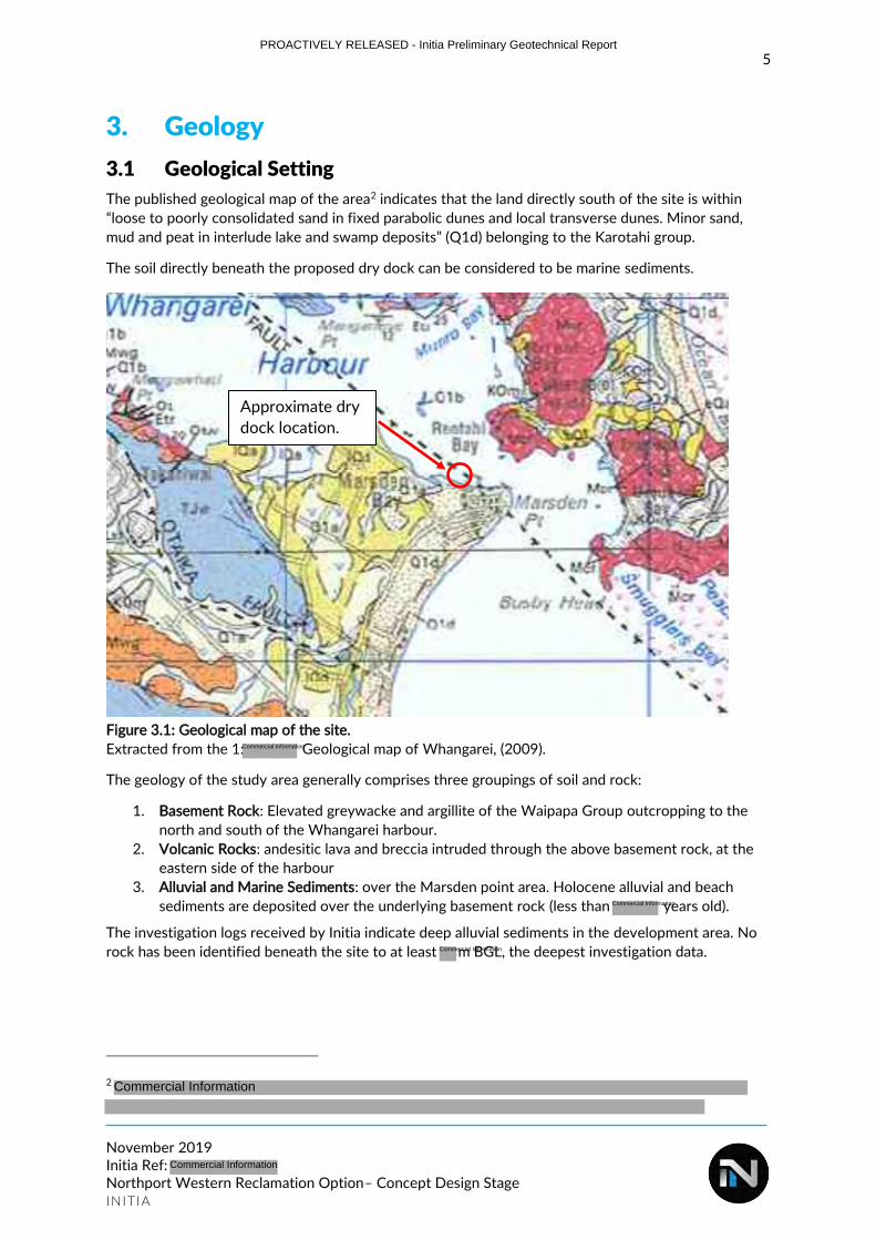
5
November 2019 Initia Ref: Northport Western Reclamation Option– Concept Design Stage INITIA
3. Geology
3.1 Geological Setting
The published geological map of the area2 indicates that the land directly south of the site is within
“loose to poorly consolidated sand in fixed parabolic dunes and local transverse dunes. Minor sand,
mud and peat in interlude lake and swamp deposits” (Q1d) belonging to the Karotahi group.
The soil directly beneath the proposed dry dock can be considered to be marine sediments.
Figure 3.1: Geological map of the site.
Extracted from the 1: Geological map of Whangarei, (2009).
The geology of the study area generally comprises three groupings of soil and rock:
1. Basement Rock: Elevated greywacke and argillite of the Waipapa Group outcropping to the
north and south of the Whangarei harbour.
2. Volcanic Rocks: andesitic lava and breccia intruded through the above basement rock, at the
eastern side of the harbour
3. Alluvial and Marine Sediments: over the Marsden point area. Holocene alluvial and beach
sediments are deposited over the underlying basement rock (less than years old).
The investigation logs received by Initia indicate deep alluvial sediments in the development area. No
rock has been identified beneath the site to at least m BGL, the deepest investigation data.
2
Approximate dry
dock location.
PROACTIVELY RELEASED - Initia Preliminary Geotechnical Report
Commercial Information
Commercial Information
Commercial Information
Commercial Information
Commercial Information
6
November 2019 Initia Ref: Northport Western Reclamation Option– Concept Design Stage INITIA
4. Subsurface Investigations
4.1 General
Subsurface investigations were undertaken between 19 September 2019 and 27 September 2019.
Field investigations comprised of rotary cored boreholes (BHs) with SPT Testing, and CPTs.
The locations of the tests were set out initially by a handheld GPS. Most of the test locations were
then picked up by a Trimble R8 GPS receiver, test location 2 was solely determined using the handheld
GPS.
Geotechnical testing of the seabed strata was made possible by using a barge provided by
. The barge contained 2 moon holes in the deck to allow access to the seabed below.
Geotech Drilling Ltd provided a tractor mounted sonic drilling rig for machine boreholes as well as a
tractor mounted CPT rig; which were both positioned over the moon holes.
Generally, the height of which the barge’s deck was set up at each test location was determined by the
height of the incoming tide. This was to ensure the base and deck of the barge was set higher than the
water level at high tide. Therefore, the deck of the barge would not flood during the drilling works and
cause a safety risk.
Boreholes and CPT tests were conducted under the supervision of an Initia engineering geologist with
soil from the boreholes logged in accordance with the NZ Geotechnical Society (NZGS) guidelines3.
4.2 Cone Penetration Testing (CPT)
Because of the depth to the seabed beneath test locations, tests were unable to penetrate to
considerable depths as expected and met practical refusal due to inclination of the CPT rods (created
by the lack of confinement above the seabed and the relatively high density of the near surface
deposits). These high density sands were observed on the CPT data.
Because of the depths to the seabed at test locations 1 & 2, CPT’s were unable to be undertaken.
Due to high winds and strong currents experienced due to bad weather during the 23 and
27 September, CPTs were unable to be attempted at test locations.
A total of 2 No. CPTs were completed (CPT-03 and CPT-04) during fine weather conditions. CPT
results and the cone calibration certificate are presented in Appendix B.
Refer to Table 1 below for a summary of the CPT tests:
3
PROACTIVELY RELEASED - Initia Preliminary Geotechnical Report
Commercial Information
Commercial Information
Commercial Information
Commercial Information
Commercial Information
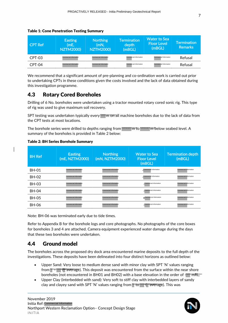
7
November 2019 Initia Ref: Northport Western Reclamation Option– Concept Design Stage INITIA
Table 1: Cone Penetration Testing Summary
CPT Ref Easting
(mE, NZTM2000)
Northing (mN,
NZTM2000)
Termination depth
(mBGL)
Water to Sea Floor Level
(mBGL)
Termination Remarks
CPT-03 Refusal
CPT-04 Refusal
We recommend that a significant amount of pre-planning and co-ordination work is carried out prior
to undertaking CPTs in these conditions given the costs involved and the lack of data obtained during
this investigation programme.
4.3 Rotary Cored Boreholes
Drilling of 6 No. boreholes were undertaken using a tractor mounted rotary cored sonic rig. This type
of rig was used to give maximum soil recovery.
SPT testing was undertaken typically every m on all machine boreholes due to the lack of data from
the CPT tests at most locations.
The borehole series were drilled to depths ranging from m to m below seabed level. A
summary of the boreholes is provided in Table 2 below:
Table 2: BH Series Borehole Summary
BH Ref Easting
(mE, NZTM2000) Northing
(mN, NZTM2000)
Water to Sea Floor Level
(mBGL)
Termination depth (mBGL)
BH-01 -
BH-02 -
BH-03 -
BH-04 -
BH-05 +
BH-06 -
Note: BH-06 was terminated early due to tide times.
Refer to Appendix B for the borehole logs and core photographs. No photographs of the core boxes
for boreholes 3 and 4 are attached. Camera equipment experienced water damage during the days
that these two boreholes were undertaken.
4.4 Ground model
The boreholes across the proposed dry dock area encountered marine deposits to the full depth of the
investigations. These deposits have been delineated into four distinct horizons as outlined below:
• Upper Sand: Very loose to medium dense sand with minor clay with SPT ‘N’ values ranging
from – ( average). This deposit was encountered from the surface within the near shore
boreholes (not encountered in BH01 and BH02) with a base elevation in the order of - mRL.
• Upper Clay (interbedded with sand): Very soft to stiff clay with interbedded layers of sandy
clay and clayey sand with SPT ‘N’ values ranging from to ( average). This was
PROACTIVELY RELEASED - Initia Preliminary Geotechnical Report
Commercial Information
Commercial Information
Commercial Information
Commercial Information
Commercial Information
Commercial Information Commercial Information
Commercial Information
Commercial Information
Commercial Information Commercial Information
Commercial Information
Commercial Information
Commercial Information
Commercial Information
Commercial Information
Commercial Information Commercial Information
Commercial Information
Commercial Information
Commercial Information
Commercial Information
Commercial Information Commercial Information
Commercial Information
Commercial Information
Commercial Information
Commercial Information
Commercial Information Commercial Information
Commercial Information
Commercial Information
Commercial Information
Commercial Information
Commercial Information
Commercial InformationCommercial InformationCommercial Information
Commercial Information
Commercial InformationCommercial InformationCommercial Information
Commercial Information

8
November 2019 Initia Ref: Northport Western Reclamation Option– Concept Design Stage INITIA
encountered below the ‘Upper sand’ (or from surface within BH01 and BH02) to a base
elevation ranging between - m and - mRL.
• Lower Sand: Medium dense to very dense sand was found across the site from RL - to -
m with SPT ‘N’ values ranging from – + (typically with a base elevation ranging
between - m and - mRL.
• Lower Clay (interbedded with sand): Very soft to very stiff clay with SPT ‘N’ values ranging
from – (18 average). This material was only encountered in BH01 below the medium
dense to very dense lower sand from RL – m to - mRL.
The geotechnical ground model, based on the data at discrete locations, is presented on the cross
sections, Figure 683-002 and 683-003 (Appendix D).
Given the thickness of the upper sand and upper clay, the ground conditions identified appear very
similar to those described in the Report – note we do not have borehole logs for the report.
PROACTIVELY RELEASED - Initia Preliminary Geotechnical Report
Commercial Information Commercial Information
Commercial Information
Commercial Information Commercial InformationCommercial Information Commercial Information
Commercial Information Commercial Information
Commercial InformationCommercial Information
Commercial Information Commercial Information
Commercial Information Commercial Information
Commercial Information
9
November 2019 Initia Ref: Northport Western Reclamation Option– Concept Design Stage INITIA
5. Laboratory Testing
5.1 Sampling
Soil samples were extracted from the Raymond split spoon from the SPT tests during the sonic
borehole testing. Generally, 4 to 5 No. samples were taken per borehole.
5.2 Laboratory Test Scheduling
A total of 32 laboratory tests were chosen to be undertaken over the 6 No. machine boreholes. These
tests included:
• A total of 25 No. samples to test for Particle Size Distribution (PSD) (14 No. wet sieve PSD,
9 No. wet sieve PSD FC only and 1 Hydrometer) were scheduled in layers of loose to very
dense clayey sands and sands identified in the boreholes over a range of depths. This
information was intended to support liquefaction susceptibility analyses.
• 7 No. samples to test for the Atterberg Limit to test the soils for their Liquid Limit, Plastic
Limit, and Plasticity Index of characteristics.
Input to the geotechnical laboratory testing schedule was also provided by the consultant team.
5.3 Laboratory Testing
Geotechnical testing of soil samples was undertaken by . A summary
table of the scheduled laboratory testing is presented in Appendix E.
Testing was carried out in accordance with the following specifications:
• Particle Size Distribution
NZS4402: 1986: Test: 2.8.1: Particle Size Distribution – standard method by wet sieving 2.8.4: Particle Size Distribution – standard method for fine soils (hydrometer method)
• Atterberg Limits
ASTM D4318 – 10e1: Standard Test Methods for Liquid Limit, Plastic Limit, and Plasticity Index of Soils
5.4 Results
Copies of all the geotechnical laboratory test results are attached in Appendix E. The borehole records
have been updated to reflect the laboratory classification.
PROACTIVELY RELEASED - Initia Preliminary Geotechnical Report
Commercial Information
Commercial Information
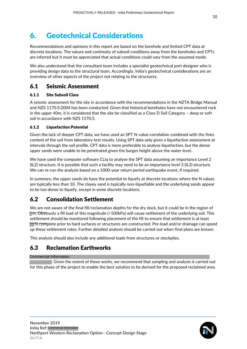
10
November 2019 Initia Ref: Northport Western Reclamation Option– Concept Design Stage INITIA
6. Geotechnical Considerations
Recommendations and opinions in this report are based on the borehole and limited CPT data at
discrete locations. The nature and continuity of subsoil conditions away from the boreholes and CPTs
are inferred but it must be appreciated that actual conditions could vary from the assumed mode.
We also understand that the consultant team includes a specialist geotechnical port designer who is
providing design data to the structural team. Accordingly, Initia’s geotechnical considerations are an
overview of other aspects of the project not relating to the structures.
6.1 Seismic Assessment
6.1.1 Site Subsoil Class
A seismic assessment for the site in accordance with the recommendations in the NZTA Bridge Manual
and NZS 1170.5:2004 has been conducted. Given that historical boreholes have not encountered rock
in the upper 40m, it is considered that the site be classified as a Class D Soil Category – deep or soft
soil in accordance with NZS 1170.5.
6.1.2 Liquefaction Potential
Given the lack of deeper CPT data, we have used an SPT N-value correlation combined with the fines
content of the soil from laboratory test results. Using SPT data only gives a liquefaction assessment at
intervals through the soil profile. CPT data is more preferable to analyse liquefaction, but the dense
upper sands were unable to be penetrated given the barges height above the water level.
We have used the computer software CLiq to analyse the SPT data assuming an importance Level 2
(IL2) structure. It is possible that such a facility may need to be an importance level 3 (IL3) structure.
We can re-run the analysis based on a 1000-year return period earthquake event, if required.
In summary, the upper sands do have the potential to liquefy at discrete locations where the N values
are typically less than 10. The clayey sand is typically non-liquefiable and the underlying sands appear
to be too dense to liquefy, except in some discrete locations.
6.2 Consolidation Settlement
We are not aware of the final fill/reclamation depths for the dry dock, but it could be in the region of
m. Obviously a fill load of this magnitude (>100kPa) will cause settlement of the underlying soil. This
settlement should be monitored following placement of the fill to ensure that settlement is at least
% complete prior to hard surfaces or structures are constructed. Pre-load and/or drainage can speed
up these settlement rates. Further detailed analysis should be carried out when final plans are known.
This analysis should also include any additional loads from structures or stockpiles.
6.3 Reclamation Earthworks
Given the extent of these works, we recommend that sampling and analysis is carried out
for this phase of the project to enable the best solution to be derived for the proposed reclaimed area.
PROACTIVELY RELEASED - Initia Preliminary Geotechnical Report
Commercial Information
Commercial Information
Commercial Information
Commercial Information
11
November 2019 Initia Ref: Northport Western Reclamation Option– Concept Design Stage INITIA
7. Further works
The work recently carried out was to provide preliminary data for a concept plan to be devised for high
level costings. The work was undertaken in a set time period for a set budget.
We consider that a more detailed geotechnical investigation is necessary to fully develop the
underlying geological model of the site.
We recommend that the second stage of investigations are only undertaken when final detailed plans
have been developed given the high costs associated with over-water investigations.
Consideration should be given to the type of investigation/equipment techniques to be used given the
lack of data obtained by the CPT due to the water depth and dense nature of the near subsurface
sands.
A targeted investigation would confirm the ground conditions across the proposed development and
would provide confidence that the design is applicable to site in terms of geotechnical considerations.
This should be investigated to confirm soils that are to be
dredged are appropriate for the extensive reclamation earthworks required for this project.
PROACTIVELY RELEASED - Initia Preliminary Geotechnical Report
Commercial Information
Commercial Information

12
November 2019 Initia Ref: Northport Western Reclamation Option– Concept Design Stage INITIA
8. Applicability
This report has been prepared for our client, Northport Ltd, with respect to the brief provided to us.
The advice and recommendations presented in this report should not be applied to any other project
or used in any other context without prior written approval from Initia Limited.
Report prepared by: Report reviewed by:
Geotechnical Engineer
Senior Geotechnical Engineer
PROACTIVELY RELEASED - Initia Preliminary Geotechnical Report
Privacy of natural persons Privacy of natural persons
Commercial Information

13
November 2019 Initia Ref: Northport Western Reclamation Option– Concept Design Stage INITIA
Document control record
Report Title Northport Western Reclamation Option– Concept Design Stage Preliminary Geotechnical Report
Initia Project Reference
Client Northport Limited
Revision Date Revision detail Author Reviewer Approved by
A 06/11/2019 Final
Current Revision A
PROACTIVELY RELEASED - Initia Preliminary Geotechnical Report
Commercial Information
Privacy of natural persons Privacy of natural persons Privacy of natural persons
Commercial Information

14
November 2019 Initia Ref: Northport Western Reclamation Option– Concept Design Stage INITIA
APPENDIX SUMMARY
PROACTIVELY RELEASED - Initia Preliminary Geotechnical Report
Commercial Information
Withheld in Full Due to Commercial Sensitivity
FLOATING DRY DOCK SIMULATION STUDY PHASE 1
PROACTIVELY RELEASED - Be-Software Phase 1 Ship Simulation Dry-docking Report
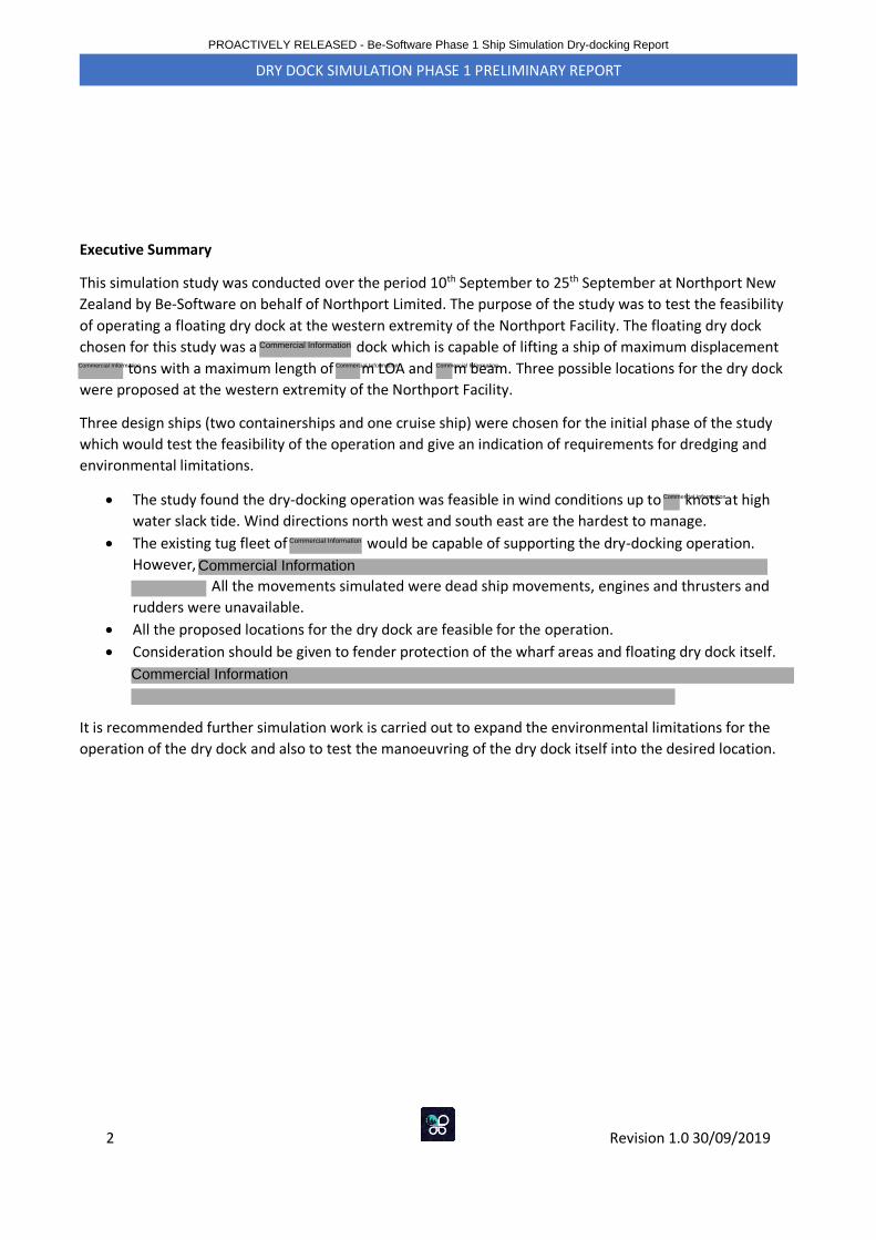
2 Revision 1.0 30/09/2019
DRY DOCK SIMULATION PHASE 1 PRELIMINARY REPORT
Executive Summary
This simulation study was conducted over the period 10th September to 25th September at Northport New
Zealand by Be-Software on behalf of Northport Limited. The purpose of the study was to test the feasibility
of operating a floating dry dock at the western extremity of the Northport Facility. The floating dry dock
chosen for this study was a dock which is capable of lifting a ship of maximum displacement
tons with a maximum length of m LOA and m beam. Three possible locations for the dry dock
were proposed at the western extremity of the Northport Facility.
Three design ships (two containerships and one cruise ship) were chosen for the initial phase of the study
which would test the feasibility of the operation and give an indication of requirements for dredging and
environmental limitations.
• The study found the dry-docking operation was feasible in wind conditions up to knots at high
water slack tide. Wind directions north west and south east are the hardest to manage.
• The existing tug fleet of would be capable of supporting the dry-docking operation.
However,
All the movements simulated were dead ship movements, engines and thrusters and
rudders were unavailable.
• All the proposed locations for the dry dock are feasible for the operation.
• Consideration should be given to fender protection of the wharf areas and floating dry dock itself.
It is recommended further simulation work is carried out to expand the environmental limitations for the
operation of the dry dock and also to test the manoeuvring of the dry dock itself into the desired location.
PROACTIVELY RELEASED - Be-Software Phase 1 Ship Simulation Dry-docking Report
Commercial Information
Commercial Information Commercial Information
Commercial Information
Commercial Information
Commercial Information
Commercial Information
Commercial Information
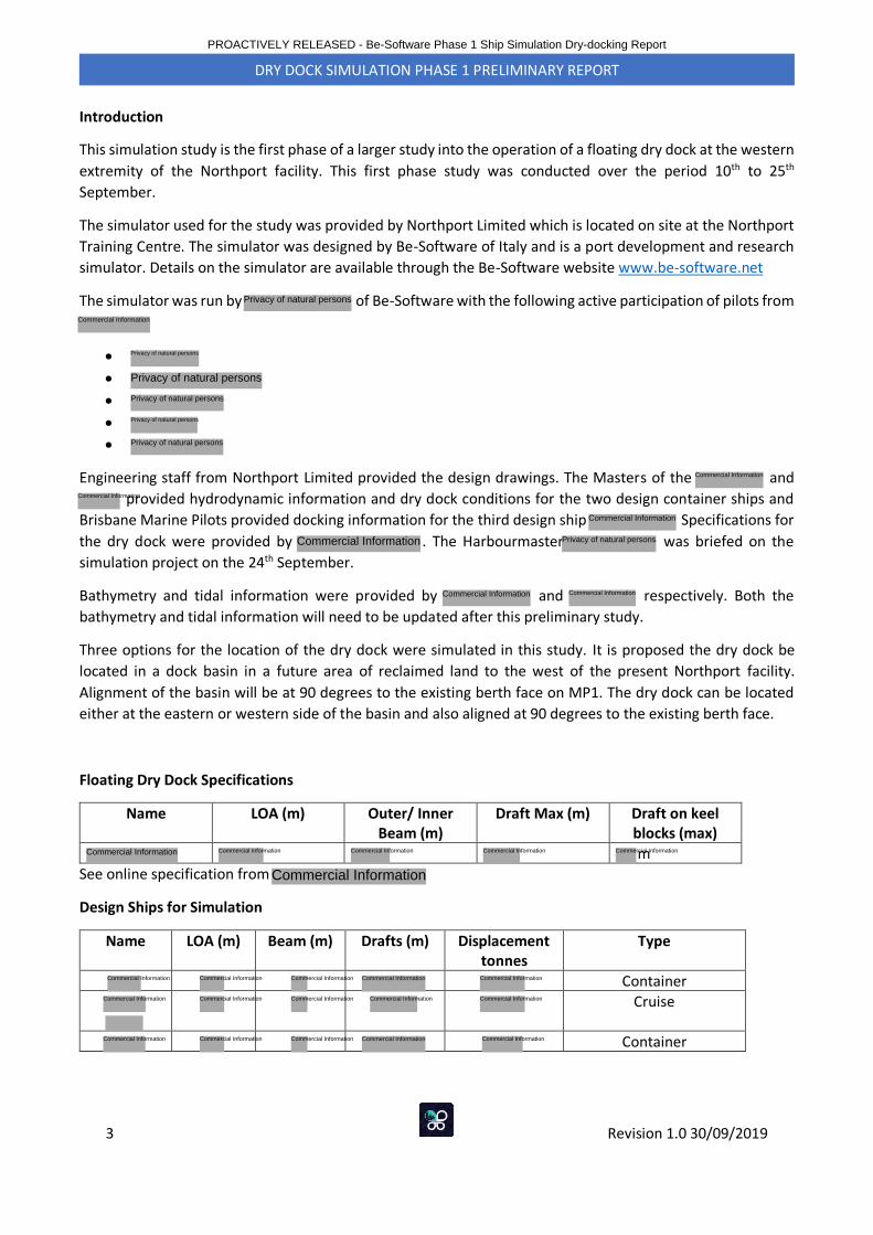
3 Revision 1.0 30/09/2019
DRY DOCK SIMULATION PHASE 1 PRELIMINARY REPORT
Introduction
This simulation study is the first phase of a larger study into the operation of a floating dry dock at the western
extremity of the Northport facility. This first phase study was conducted over the period 10th to 25th
September.
The simulator used for the study was provided by Northport Limited which is located on site at the Northport
Training Centre. The simulator was designed by Be-Software of Italy and is a port development and research
simulator. Details on the simulator are available through the Be-Software website www.be-software.net
The simulator was run by of Be-Software with the following active participation of pilots from
•••••
Engineering staff from Northport Limited provided the design drawings. The Masters of the and
provided hydrodynamic information and dry dock conditions for the two design container ships and
Brisbane Marine Pilots provided docking information for the third design ship Specifications for
the dry dock were provided by . The Harbourmaster was briefed on the
simulation project on the 24th September.
Bathymetry and tidal information were provided by and respectively. Both the
bathymetry and tidal information will need to be updated after this preliminary study.
Three options for the location of the dry dock were simulated in this study. It is proposed the dry dock be
located in a dock basin in a future area of reclaimed land to the west of the present Northport facility.
Alignment of the basin will be at 90 degrees to the existing berth face on MP1. The dry dock can be located
either at the eastern or western side of the basin and also aligned at 90 degrees to the existing berth face.
Floating Dry Dock Specifications
Name LOA (m) Outer/ Inner Beam (m)
Draft Max (m) Draft on keel blocks (max)
m
See online specification from
Design Ships for Simulation
Name LOA (m) Beam (m) Drafts (m) Displacement tonnes
Type
Container
Cruise
Container
PROACTIVELY RELEASED - Be-Software Phase 1 Ship Simulation Dry-docking Report
Privacy of natural persons
Commercial Information
Privacy of natural persons
Privacy of natural persons
Privacy of natural persons
Privacy of natural persons
Privacy of natural persons
Commercial Information
Commercial Information
Commercial Information
Privacy of natural persons
Commercial Information Commercial Information
Commercial Information Commercial Information Commercial Information Commercial Information Commercial Information
Commercial Information
Commercial Information
Commercial Information
Commercial Information Commercial Information
Commercial Information
Commercial Information Commercial Information
Commercial Information
Commercial Information
Commercial Information
Commercial Information
Commercial Information Commercial Information
Commercial Information
Commercial Information
Commercial Information
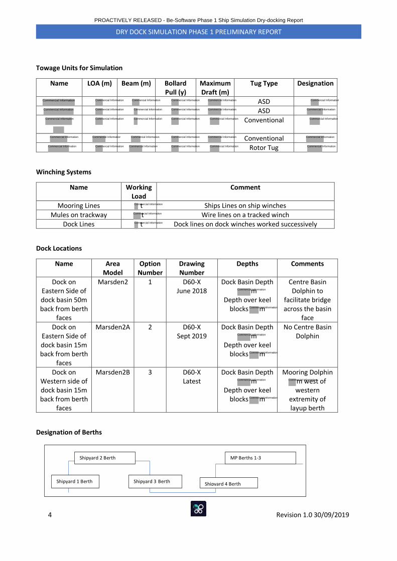
4 Revision 1.0 30/09/2019
DRY DOCK SIMULATION PHASE 1 PRELIMINARY REPORT
Towage Units for Simulation
Name LOA (m) Beam (m) Bollard Pull (y)
Maximum Draft (m)
Tug Type Designation
ASD
ASD
Conventional
Conventional
Rotor Tug
Winching Systems
Name Working Load
Comment
Mooring Lines t Ships Lines on ship winches
Mules on trackway t Wire lines on a tracked winch
Dock Lines t Dock lines on dock winches worked successively
Dock Locations
Name Area Model
Option Number
Drawing Number
Depths Comments
Dock on Eastern Side of dock basin 50m back from berth
faces
Marsden2 1 D60-X June 2018
Dock Basin Depth m
Depth over keel blocks m
Centre Basin Dolphin to
facilitate bridge across the basin
face
Dock on Eastern Side of dock basin 15m back from berth
faces
Marsden2A 2 D60-X Sept 2019
Dock Basin Depth m
Depth over keel blocks m
No Centre Basin Dolphin
Dock on Western side of dock basin 15m back from berth
faces
Marsden2B 3 D60-X Latest
Dock Basin Depth m
Depth over keel blocks m
Mooring Dolphin m west of western
extremity of layup berth
Designation of Berths
Shipyard 1 Berth
Shipyard 2 Berth
Shipyard 3 Berth Shipyard 4 Berth
MP Berths 1-3
PROACTIVELY RELEASED - Be-Software Phase 1 Ship Simulation Dry-docking Report
Commercial Information
Commercial Information
Commercial Information
Commercial Information
Commercial Information Commercial Information
Commercial Information
Commercial Information
Commercial Information
Commercial Information Commercial Information
Commercial Information
Commercial Information
Commercial Information
Commercial Information Commercial Information
Commercial Information
Commercial Information
Commercial Information
Commercial Information
Commercial Information
Commercial Information
Commercial Information
Commercial Information
Commercial Information
Commercial Information
Commercial Information
Commercial Information
Commercial Information
Commercial Information
Commercial Information
Commercial Information
Commercial Information
Commercial Information
Commercial Information
Commercial Information
Commercial Information
Commercial Information
Commercial Information
Commercial Information
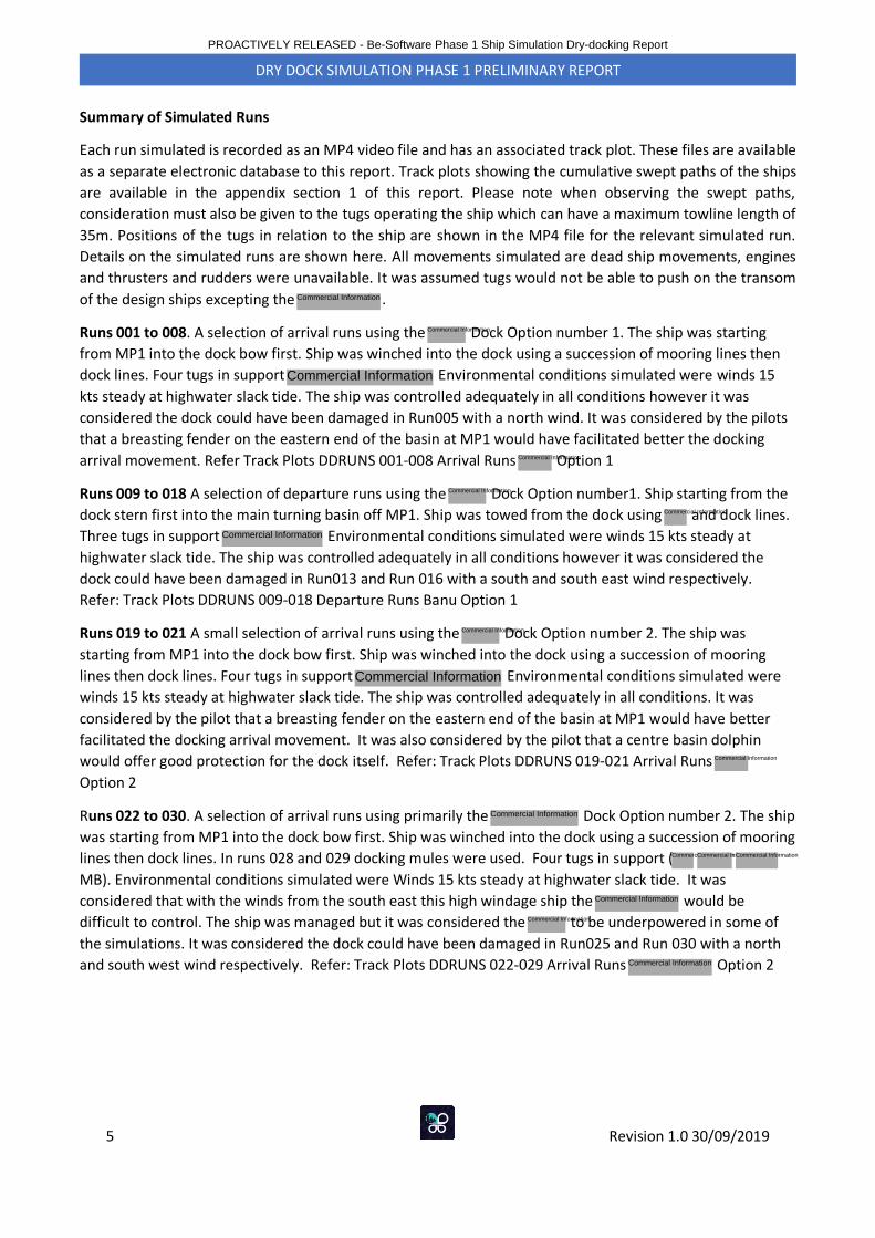
5 Revision 1.0 30/09/2019
DRY DOCK SIMULATION PHASE 1 PRELIMINARY REPORT
Summary of Simulated Runs
Each run simulated is recorded as an MP4 video file and has an associated track plot. These files are available
as a separate electronic database to this report. Track plots showing the cumulative swept paths of the ships
are available in the appendix section 1 of this report. Please note when observing the swept paths,
consideration must also be given to the tugs operating the ship which can have a maximum towline length of
35m. Positions of the tugs in relation to the ship are shown in the MP4 file for the relevant simulated run.
Details on the simulated runs are shown here. All movements simulated are dead ship movements, engines
and thrusters and rudders were unavailable. It was assumed tugs would not be able to push on the transom
of the design ships excepting the .
Runs 001 to 008. A selection of arrival runs using the Dock Option number 1. The ship was starting
from MP1 into the dock bow first. Ship was winched into the dock using a succession of mooring lines then
dock lines. Four tugs in support Environmental conditions simulated were winds 15
kts steady at highwater slack tide. The ship was controlled adequately in all conditions however it was
considered the dock could have been damaged in Run005 with a north wind. It was considered by the pilots
that a breasting fender on the eastern end of the basin at MP1 would have facilitated better the docking
arrival movement. Refer Track Plots DDRUNS 001-008 Arrival Runs Option 1
Runs 009 to 018 A selection of departure runs using the Dock Option number1. Ship starting from the
dock stern first into the main turning basin off MP1. Ship was towed from the dock using and dock lines.
Three tugs in support Environmental conditions simulated were winds 15 kts steady at
highwater slack tide. The ship was controlled adequately in all conditions however it was considered the
dock could have been damaged in Run013 and Run 016 with a south and south east wind respectively.
Refer: Track Plots DDRUNS 009-018 Departure Runs Banu Option 1
Runs 019 to 021 A small selection of arrival runs using the Dock Option number 2. The ship was
starting from MP1 into the dock bow first. Ship was winched into the dock using a succession of mooring
lines then dock lines. Four tugs in support Environmental conditions simulated were
winds 15 kts steady at highwater slack tide. The ship was controlled adequately in all conditions. It was
considered by the pilot that a breasting fender on the eastern end of the basin at MP1 would have better
facilitated the docking arrival movement. It was also considered by the pilot that a centre basin dolphin
would offer good protection for the dock itself. Refer: Track Plots DDRUNS 019-021 Arrival Runs
Option 2
Runs 022 to 030. A selection of arrival runs using primarily the Dock Option number 2. The ship
was starting from MP1 into the dock bow first. Ship was winched into the dock using a succession of mooring
lines then dock lines. In runs 028 and 029 docking mules were used. Four tugs in support (
MB). Environmental conditions simulated were Winds 15 kts steady at highwater slack tide. It was
considered that with the winds from the south east this high windage ship the would be
difficult to control. The ship was managed but it was considered the to be underpowered in some of
the simulations. It was considered the dock could have been damaged in Run025 and Run 030 with a north
and south west wind respectively. Refer: Track Plots DDRUNS 022-029 Arrival Runs Option 2
PROACTIVELY RELEASED - Be-Software Phase 1 Ship Simulation Dry-docking Report
Commercial Information
Commercial Information
Commercial Information
Commercial Information
Commercial Information
Commercial Information
Commercial InformationCommercial InformationCommercial Information
Commercial Information
Commercial Information
Commercial Information
Commercial Information
Commercial Information
Commercial Information
Commercial Information
Commercial Information
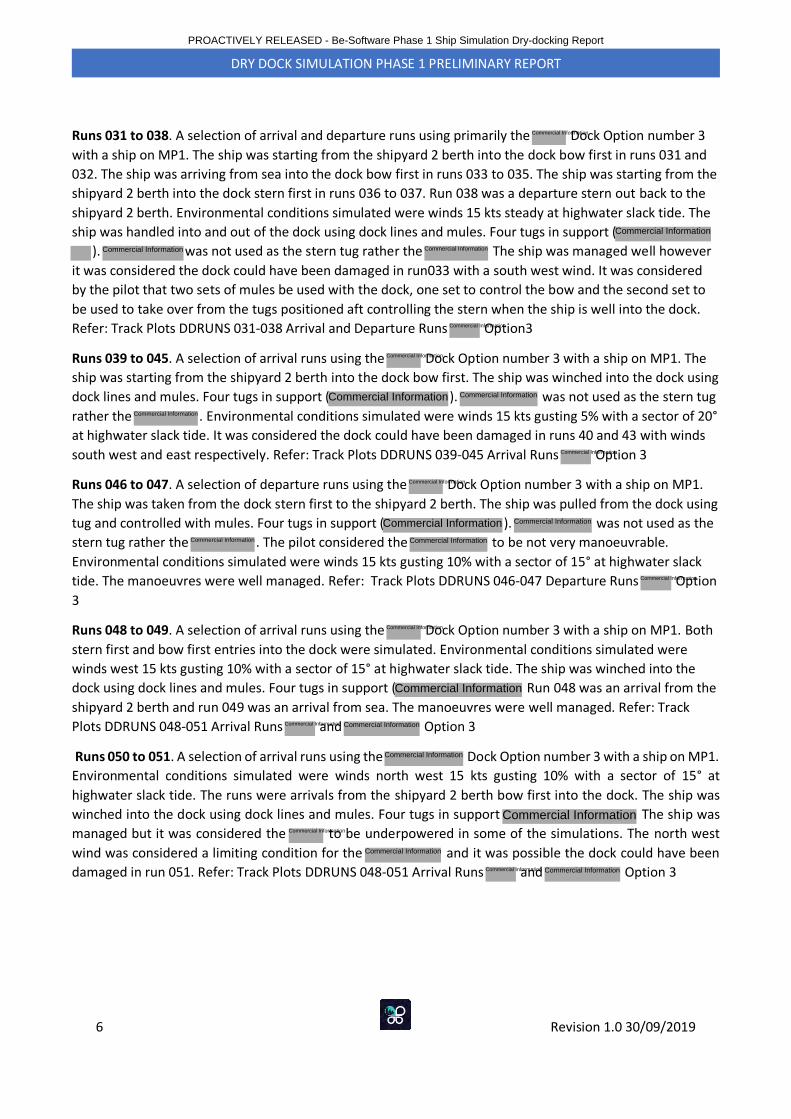
6 Revision 1.0 30/09/2019
DRY DOCK SIMULATION PHASE 1 PRELIMINARY REPORT
Runs 031 to 038. A selection of arrival and departure runs using primarily the Dock Option number 3
with a ship on MP1. The ship was starting from the shipyard 2 berth into the dock bow first in runs 031 and
032. The ship was arriving from sea into the dock bow first in runs 033 to 035. The ship was starting from the
shipyard 2 berth into the dock stern first in runs 036 to 037. Run 038 was a departure stern out back to the
shipyard 2 berth. Environmental conditions simulated were winds 15 kts steady at highwater slack tide. The
ship was handled into and out of the dock using dock lines and mules. Four tugs in support (
). was not used as the stern tug rather the The ship was managed well however
it was considered the dock could have been damaged in run033 with a south west wind. It was considered
by the pilot that two sets of mules be used with the dock, one set to control the bow and the second set to
be used to take over from the tugs positioned aft controlling the stern when the ship is well into the dock.
Refer: Track Plots DDRUNS 031-038 Arrival and Departure Runs Option3
Runs 039 to 045. A selection of arrival runs using the Dock Option number 3 with a ship on MP1. The
ship was starting from the shipyard 2 berth into the dock bow first. The ship was winched into the dock using
dock lines and mules. Four tugs in support ( ). was not used as the stern tug
rather the . Environmental conditions simulated were winds 15 kts gusting 5% with a sector of 20°
at highwater slack tide. It was considered the dock could have been damaged in runs 40 and 43 with winds
south west and east respectively. Refer: Track Plots DDRUNS 039-045 Arrival Runs Option 3
Runs 046 to 047. A selection of departure runs using the Dock Option number 3 with a ship on MP1.
The ship was taken from the dock stern first to the shipyard 2 berth. The ship was pulled from the dock using
tug and controlled with mules. Four tugs in support ( ). was not used as the
stern tug rather the . The pilot considered the to be not very manoeuvrable.
Environmental conditions simulated were winds 15 kts gusting 10% with a sector of 15° at highwater slack
tide. The manoeuvres were well managed. Refer: Track Plots DDRUNS 046-047 Departure Runs Option
3
Runs 048 to 049. A selection of arrival runs using the Dock Option number 3 with a ship on MP1. Both
stern first and bow first entries into the dock were simulated. Environmental conditions simulated were
winds west 15 kts gusting 10% with a sector of 15° at highwater slack tide. The ship was winched into the
dock using dock lines and mules. Four tugs in support ( Run 048 was an arrival from the
shipyard 2 berth and run 049 was an arrival from sea. The manoeuvres were well managed. Refer: Track
Plots DDRUNS 048-051 Arrival Runs and Option 3
Runs 050 to 051. A selection of arrival runs using the Dock Option number 3 with a ship on MP1.
Environmental conditions simulated were winds north west 15 kts gusting 10% with a sector of 15° at
highwater slack tide. The runs were arrivals from the shipyard 2 berth bow first into the dock. The ship was
winched into the dock using dock lines and mules. Four tugs in support The ship was
managed but it was considered the to be underpowered in some of the simulations. The north west
wind was considered a limiting condition for the and it was possible the dock could have been
damaged in run 051. Refer: Track Plots DDRUNS 048-051 Arrival Runs and Option 3
PROACTIVELY RELEASED - Be-Software Phase 1 Ship Simulation Dry-docking Report
Commercial Information
Commercial Information
Commercial Information Commercial Information
Commercial Information
Commercial Information
Commercial Information Commercial Information
Commercial Information
Commercial Information
Commercial Information
Commercial Information
Commercial Information
Commercial Information
Commercial Information Commercial Information
Commercial Information
Commercial Information
Commercial Information Commercial Information
Commercial Information
Commercial InformationCommercial Information
Commercial Information
Commercial Information Commercial Information
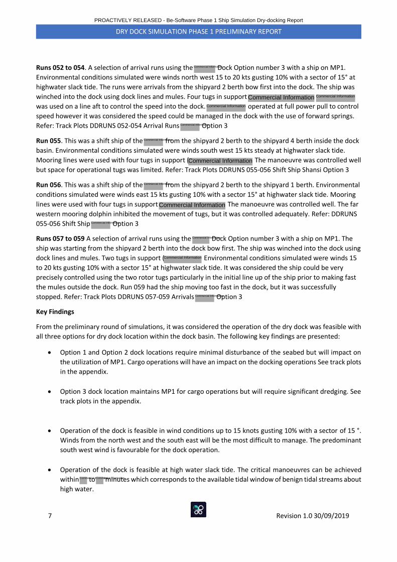
7 Revision 1.0 30/09/2019
DRY DOCK SIMULATION PHASE 1 PRELIMINARY REPORT
Runs 052 to 054. A selection of arrival runs using the Dock Option number 3 with a ship on MP1.
Environmental conditions simulated were winds north west 15 to 20 kts gusting 10% with a sector of 15° at
highwater slack tide. The runs were arrivals from the shipyard 2 berth bow first into the dock. The ship was
winched into the dock using dock lines and mules. Four tugs in support
was used on a line aft to control the speed into the dock. operated at full power pull to control
speed however it was considered the speed could be managed in the dock with the use of forward springs.
Refer: Track Plots DDRUNS 052-054 Arrival Runs Option 3
Run 055. This was a shift ship of the from the shipyard 2 berth to the shipyard 4 berth inside the dock
basin. Environmental conditions simulated were winds south west 15 kts steady at highwater slack tide.
Mooring lines were used with four tugs in support ( The manoeuvre was controlled well
but space for operational tugs was limited. Refer: Track Plots DDRUNS 055-056 Shift Ship Shansi Option 3
Run 056. This was a shift ship of the from the shipyard 2 berth to the shipyard 1 berth. Environmental
conditions simulated were winds east 15 kts gusting 10% with a sector 15° at highwater slack tide. Mooring
lines were used with four tugs in support The manoeuvre was controlled well. The far
western mooring dolphin inhibited the movement of tugs, but it was controlled adequately. Refer: DDRUNS
055-056 Shift Ship Option 3
Runs 057 to 059 A selection of arrival runs using the Dock Option number 3 with a ship on MP1. The
ship was starting from the shipyard 2 berth into the dock bow first. The ship was winched into the dock using
dock lines and mules. Two tugs in support ( Environmental conditions simulated were winds 15
to 20 kts gusting 10% with a sector 15° at highwater slack tide. It was considered the ship could be very
precisely controlled using the two rotor tugs particularly in the initial line up of the ship prior to making fast
the mules outside the dock. Run 059 had the ship moving too fast in the dock, but it was successfully
stopped. Refer: Track Plots DDRUNS 057-059 Arrivals Option 3
Key Findings
From the preliminary round of simulations, it was considered the operation of the dry dock was feasible with
all three options for dry dock location within the dock basin. The following key findings are presented:
• Option 1 and Option 2 dock locations require minimal disturbance of the seabed but will impact on
the utilization of MP1. Cargo operations will have an impact on the docking operations See track plots
in the appendix.
• Option 3 dock location maintains MP1 for cargo operations but will require significant dredging. See
track plots in the appendix.
• Operation of the dock is feasible in wind conditions up to 15 knots gusting 10% with a sector of 15 °.
Winds from the north west and the south east will be the most difficult to manage. The predominant
south west wind is favourable for the dock operation.
• Operation of the dock is feasible at high water slack tide. The critical manoeuvres can be achieved
within to minutes which corresponds to the available tidal window of benign tidal streams about
high water.
PROACTIVELY RELEASED - Be-Software Phase 1 Ship Simulation Dry-docking Report
Commercial Information
Commercial Information Commercial Information
Commercial Information
Commercial Information
Commercial Information
Commercial Information
Commercial Information
Commercial Information
Commercial Information
Commercial Information
Commercial Information
Commercial Information
Commercial InformationCommercial Information
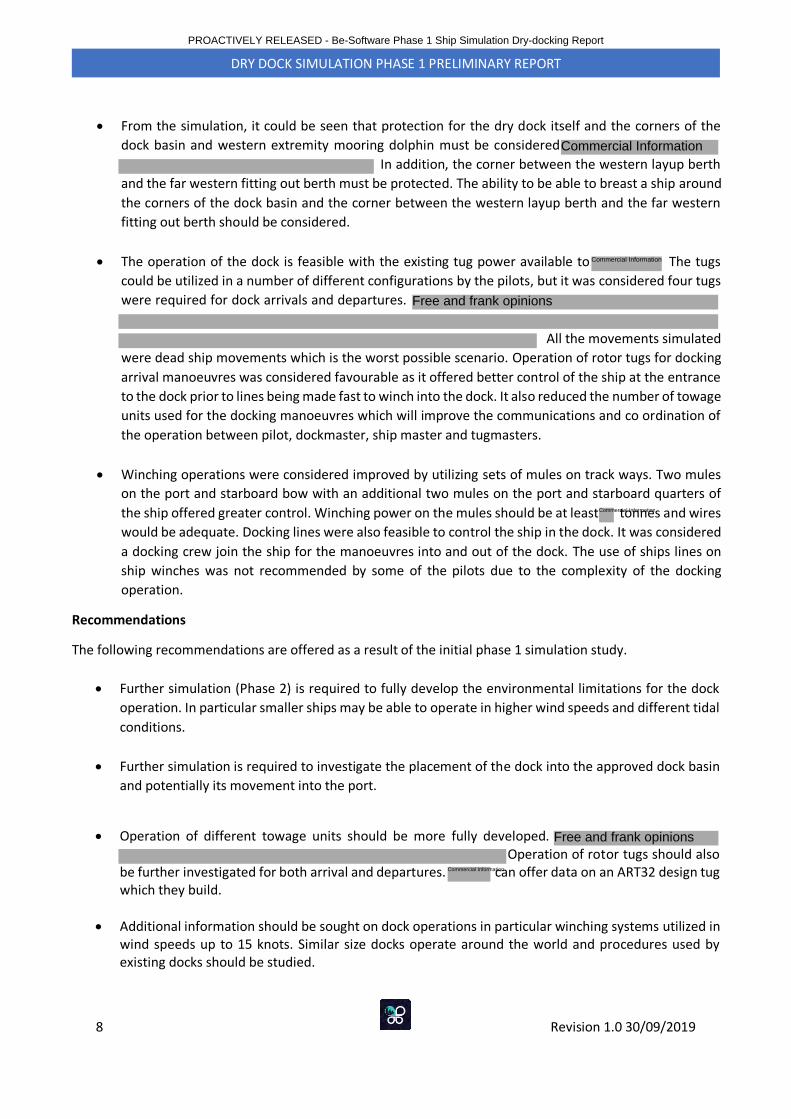
8 Revision 1.0 30/09/2019
DRY DOCK SIMULATION PHASE 1 PRELIMINARY REPORT
• From the simulation, it could be seen that protection for the dry dock itself and the corners of the
dock basin and western extremity mooring dolphin must be considered
In addition, the corner between the western layup berth
and the far western fitting out berth must be protected. The ability to be able to breast a ship around
the corners of the dock basin and the corner between the western layup berth and the far western
fitting out berth should be considered.
• The operation of the dock is feasible with the existing tug power available to The tugs
could be utilized in a number of different configurations by the pilots, but it was considered four tugs
were required for dock arrivals and departures.
All the movements simulated
were dead ship movements which is the worst possible scenario. Operation of rotor tugs for docking
arrival manoeuvres was considered favourable as it offered better control of the ship at the entrance
to the dock prior to lines being made fast to winch into the dock. It also reduced the number of towage
units used for the docking manoeuvres which will improve the communications and co ordination of
the operation between pilot, dockmaster, ship master and tugmasters.
• Winching operations were considered improved by utilizing sets of mules on track ways. Two mules
on the port and starboard bow with an additional two mules on the port and starboard quarters of
the ship offered greater control. Winching power on the mules should be at least tonnes and wires
would be adequate. Docking lines were also feasible to control the ship in the dock. It was considered
a docking crew join the ship for the manoeuvres into and out of the dock. The use of ships lines on
ship winches was not recommended by some of the pilots due to the complexity of the docking
operation.
Recommendations
The following recommendations are offered as a result of the initial phase 1 simulation study.
• Further simulation (Phase 2) is required to fully develop the environmental limitations for the dock
operation. In particular smaller ships may be able to operate in higher wind speeds and different tidal
conditions.
• Further simulation is required to investigate the placement of the dock into the approved dock basin
and potentially its movement into the port.
• Operation of different towage units should be more fully developed. Operation of rotor tugs should also
be further investigated for both arrival and departures. can offer data on an ART32 design tugwhich they build.
• Additional information should be sought on dock operations in particular winching systems utilized inwind speeds up to 15 knots. Similar size docks operate around the world and procedures used byexisting docks should be studied.
PROACTIVELY RELEASED - Be-Software Phase 1 Ship Simulation Dry-docking Report
Commercial Information
Commercial Information
Free and frank opinions
Commercial Information
Free and frank opinions
Commercial Information
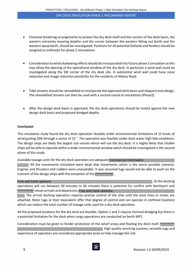
9 Revision 1.0 30/09/2019
DRY DOCK SIMULATION PHASE 1 PRELIMINARY REPORT
• Potential fendering arrangements to protect the dry dock itself and the corners of the dock basin, thewestern extremity mooring dolphin and the corner between the western fitting out berth and thewestern layup berth, should be investigated. Positions for all potential bollards and fenders should beassigned co ordinates for phase 2 simulations.
• Consideration to wind shadowing effects should be incorporated into future phase 2 simulation as thismay allow the opening of the operational window of the dry dock. In particular a wind wall could beinvestigated along the SW corner of the dry dock site. A substantial wind wall could have noisereduction and image reduction possibility for the residents of Albany Road.
• Tidal streams should be remodelled to incorporate the approved dock basin and shipyard area design.The remodelled streams can then be used with a second round of simulations (Phase2)
• After the design dock basin is approved, the dry dock operations should be tested against the newdesign dock basin and proposed dredged depths.
Conclusion
This simulation study found the dry dock operation feasible under environmental limitations of 15 knots of
wind gusting 10% through a sector of 15 °. The operation was feasible under slack water high tide conditions.
The design ships are likely the largest size vessels which will use the dry dock. It is highly likely that smaller
ships will be able to operate within a wider environmental window which should be investigated in the second
phase of this study.
Available towage units for the dry dock operation are adequate
All the movements simulated were dead ship movements which is the worst possible scenario.
Engines and thrusters and rudders were unavailable. It was assumed tugs would not be able to push on the
transom of the design ships with the exception of the .
. As the docking
operations will run between 30 minutes to 60 minutes there is potential for conflict with Northport and
vessel arrivals and departures.
The arrival docking operation requires precise control of the ship until the dock lines or mules are
attached. Rotor tugs or their equivalent offer that degree of control and can operate in confined locations
which can reduce the total number of towage units used for a dry dock operation.
All the proposed locations for the dry dock are feasible. Option 1 and 2 require minimal dredging but there is
a potential limitation for the dock when cargo operations are conducted on berth MP1.
Consideration must be given to fender protection of the wharf areas and floating dry dock itself.
High quality winching systems, versatile tugs and
experience of operators are considered appropriate tools to help manage this risk.
PROACTIVELY RELEASED - Be-Software Phase 1 Ship Simulation Dry-docking Report
Commercial Information
Free and frank opinions
Commercial Information Free and frank opinions
Commercial Information
Commercial Information
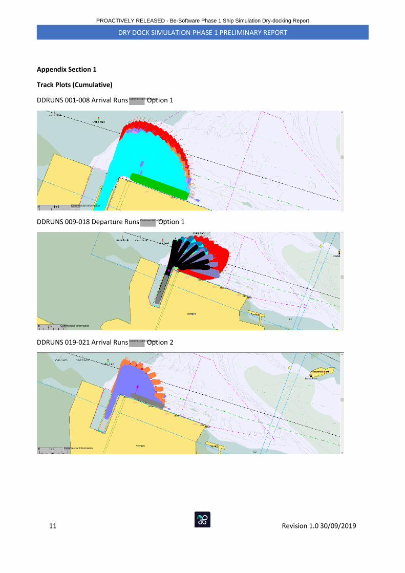
11 Revision 1.0 30/09/2019
DRY DOCK SIMULATION PHASE 1 PRELIMINARY REPORT
Appendix Section 1
Track Plots (Cumulative)
DDRUNS 001-008 Arrival Runs Option 1
DDRUNS 009-018 Departure Runs Option 1
DDRUNS 019-021 Arrival Runs Option 2
PROACTIVELY RELEASED - Be-Software Phase 1 Ship Simulation Dry-docking Report
Commercial Information
Commercial Information
Commercial Information
Commercial Information
Commercial Information
Commercial Information
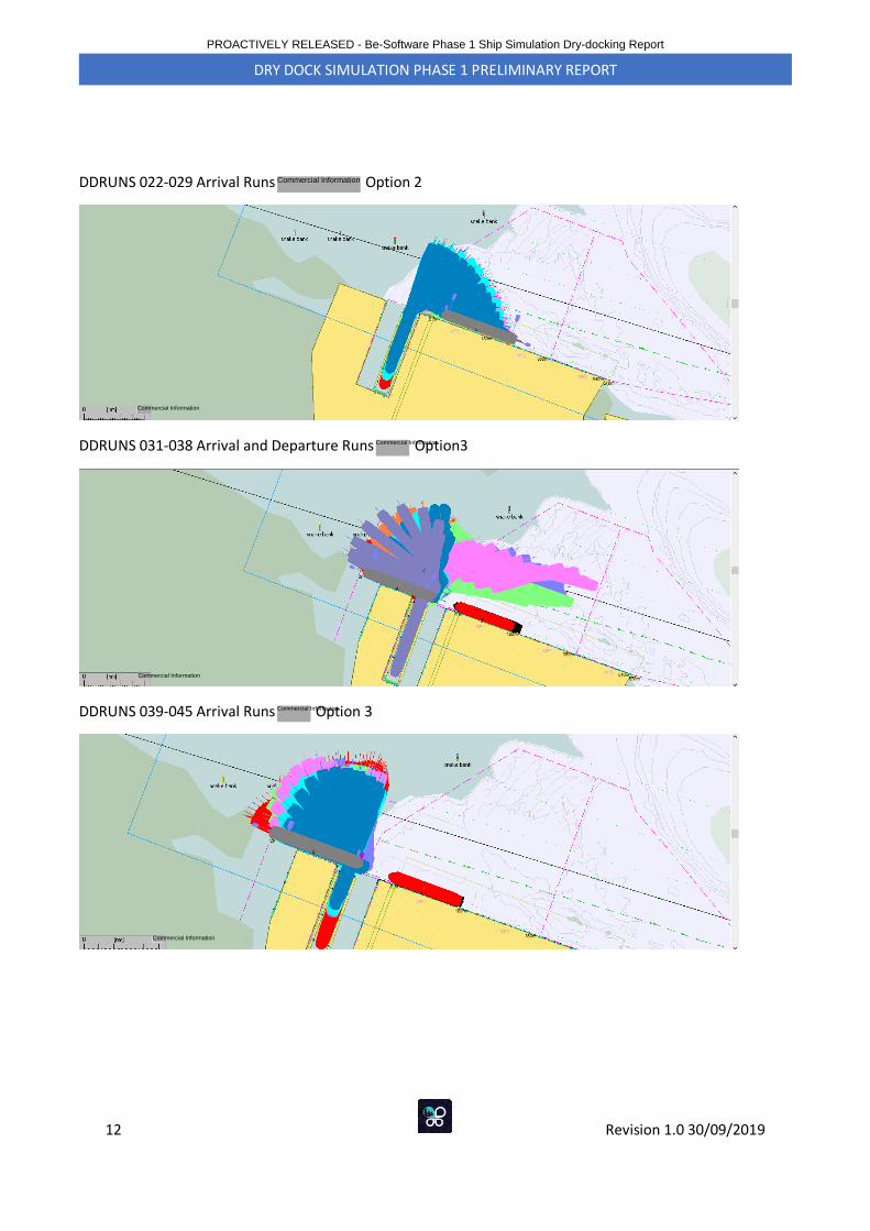
12 Revision 1.0 30/09/2019
DRY DOCK SIMULATION PHASE 1 PRELIMINARY REPORT
DDRUNS 022-029 Arrival Runs Option 2
DDRUNS 031-038 Arrival and Departure Runs Option3
DDRUNS 039-045 Arrival Runs Option 3
PROACTIVELY RELEASED - Be-Software Phase 1 Ship Simulation Dry-docking Report
Commercial Information
Commercial Information
Commercial Information
Commercial Information
Commercial Information
Commercial Information
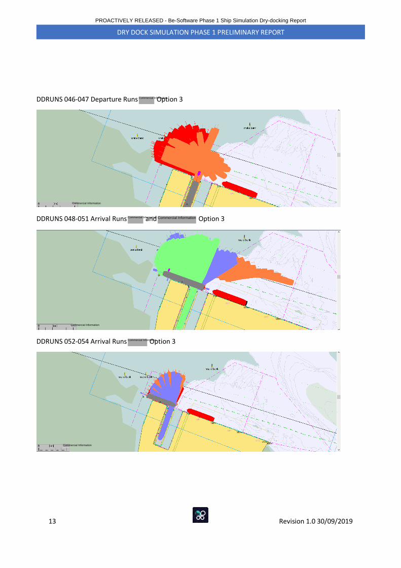
13 Revision 1.0 30/09/2019
DRY DOCK SIMULATION PHASE 1 PRELIMINARY REPORT
DDRUNS 046-047 Departure Runs Option 3
DDRUNS 048-051 Arrival Runs and Option 3
DDRUNS 052-054 Arrival Runs Option 3
PROACTIVELY RELEASED - Be-Software Phase 1 Ship Simulation Dry-docking Report
Commercial Information
Commercial Information
Commercial Information
Commercial Information
Commercial Information
Commercial Information
Commercial Information
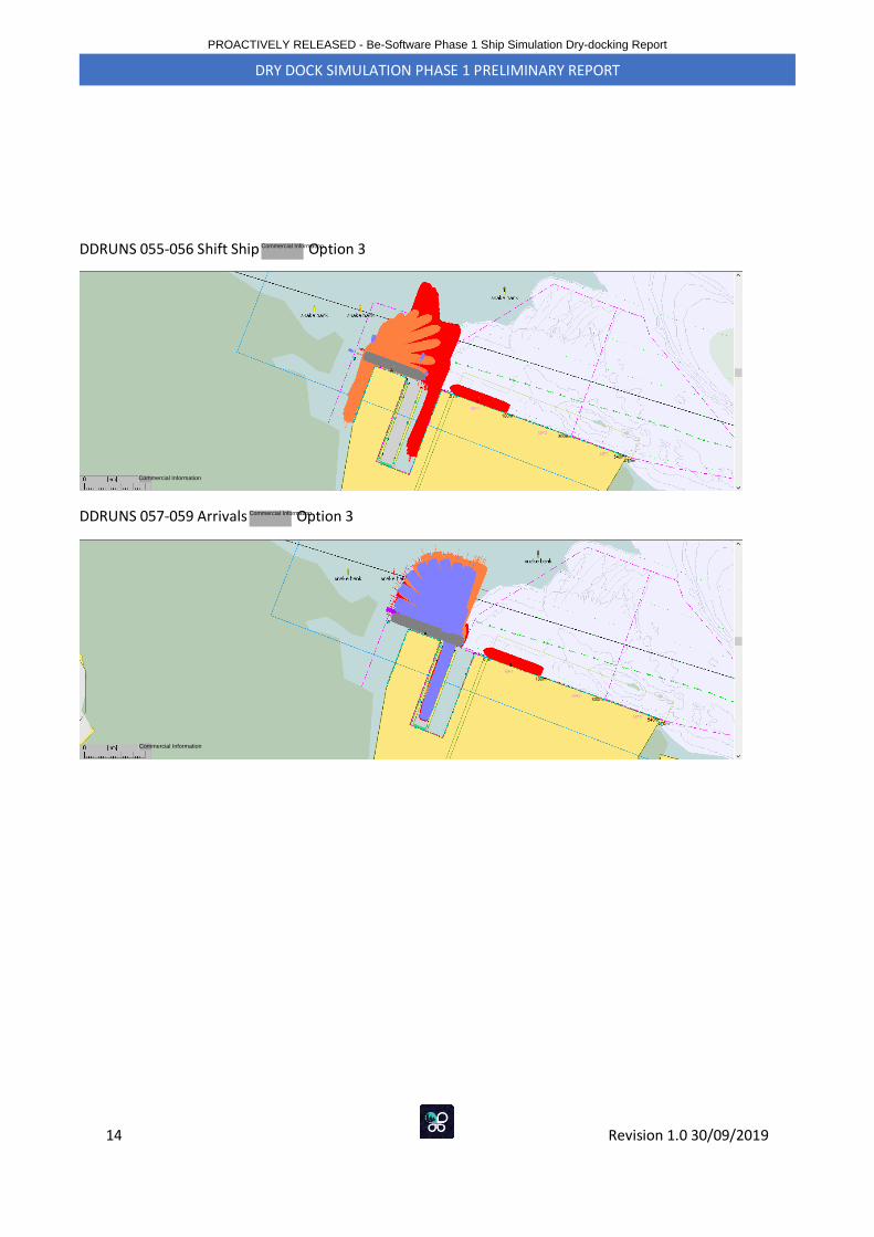
14 Revision 1.0 30/09/2019
DRY DOCK SIMULATION PHASE 1 PRELIMINARY REPORT
DDRUNS 055-056 Shift Ship Option 3
DDRUNS 057-059 Arrivals Option 3
PROACTIVELY RELEASED - Be-Software Phase 1 Ship Simulation Dry-docking Report
Commercial Information
Commercial Information
Commercial Information
Commercial Information
Northland Shipyard & Floating Drydock Project
CONSENTING PROCESS
1. Consenting Process:
There are three resource consent processes which may be followed in relation to the required resource consents for the reclamation:
1. The default process under the RMA
2. Direct referral to the Environment Court
3. Referral to the Environmental Protection Agency (EPA)
2. Consents Required:
Resource consents will be required in respect to the following matters:
• Reclamation
• Structures occupying space in the CMA
• Structures in the CMA
• Earthworks in the coastal marine area (construction)
• Stormwater discharge (during construction)
• Stormwater discharge (post construction)
• Capital dredging (including turning basin)
• Maintenance dredging
• Disposal of dredge material to land and/or into CMA
• Land use post construction (i.e. port related activities)
3. Supporting Information:
The application for the resource consents will require the following supporting technical information/reports:
• Visual/Landscape assessment
• Noise assessment; including noise predictions and modelling
• Air quality
• Economic effects
• Recreational effects
• Transport assessment
• Archaeological assessment
• Cultural assessment (Patuharakeke): Cultural Values & Cultural Effects
• Ecological assessment (shellfish, birds, marine ecology)
PROACTIVELY RELEASED - Consenting Process Report
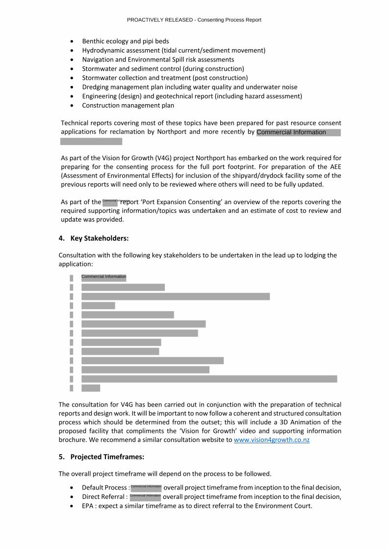
• Benthic ecology and pipi beds
• Hydrodynamic assessment (tidal current/sediment movement)
• Navigation and Environmental Spill risk assessments
• Stormwater and sediment control (during construction)
• Stormwater collection and treatment (post construction)
• Dredging management plan including water quality and underwater noise
• Engineering (design) and geotechnical report (including hazard assessment)
• Construction management plan Technical reports covering most of these topics have been prepared for past resource consent applications for reclamation by Northport and more recently by
As part of the Vision for Growth (V4G) project Northport has embarked on the work required for preparing for the consenting process for the full port footprint. For preparation of the AEE (Assessment of Environmental Effects) for inclusion of the shipyard/drydock facility some of the previous reports will need only to be reviewed where others will need to be fully updated. As part of the report ‘Port Expansion Consenting’ an overview of the reports covering the required supporting information/topics was undertaken and an estimate of cost to review and update was provided.
4. Key Stakeholders:
Consultation with the following key stakeholders to be undertaken in the lead up to lodging the application:
The consultation for V4G has been carried out in conjunction with the preparation of technical reports and design work. It will be important to now follow a coherent and structured consultation process which should be determined from the outset; this will include a 3D Animation of the proposed facility that compliments the ‘Vision for Growth’ video and supporting information brochure. We recommend a similar consultation website to www.vision4growth.co.nz
5. Projected Timeframes:
The overall project timeframe will depend on the process to be followed.
• Default Process : overall project timeframe from inception to the final decision,
• Direct Referral : overall project timeframe from inception to the final decision,
• EPA : expect a similar timeframe as to direct referral to the Environment Court.
PROACTIVELY RELEASED - Consenting Process Report
Commercial Information
Commercial Information
Commercial Information
Commercial Information
Commercial Information
6. Projected Costs:
The potential costs associated with obtaining the necessary resource consents depends on the process to be followed and to a certain extent, the strength of any opposition to the project. While the direct referral and EPA processes avoid the duplication associated with attendance at both a Council and Environment Court hearing, the costs associated with these processes are significant.
The overall cost of obtaining consent has been based on the Stage 2 consenting project and is
expected to range between $ and $ depending on which process is followed.
7. Proposal:
• Undertake a full review of the technical reports available from previous consent applications and reports available from identify the reports that can be updated and the areas where new reports are required,
• Update existing reports and use for technical investigations to assess the environmental effects of the proposed reclamation(s) and activities,
• Undertake new technical investigations where required and provide reports for assessment of environmental effects,
• Structure and commence consultation process,
• Pre-lodgement meetings with Northland Regional Council / Whangarei District Council,
• Prepare consent applications,
• Pre-lodgement meetings with Northport Directors and confirmation to move forward,
• Default process under RMA – application to NRC,
• Concurrent applications to be made but as separate consents.
8. Potential consenting issues: • Historically, the ability to obtain consents for work of this nature has become more
difficult and therefore more expensive as time passes.
• Current status of the Regional Plan; the proposed Regional Plan has legal effect, but several aspects of the plan are under appeal that potentially affect this project;
• Areas mapped as SEA (Significant Ecological Areas) are under appeal; of significance to this project is the area directly to the west of the port facility – i.e. proposed site for shipyard;
• Forest & Bird have made an appeal to have the status of SBA (Significant Bird Areas) elevated in the Regional Plan, if this is successful it will create additional consenting issues for this project;
• Implications going forward of the customary marine title claims made under the Marine & Coastal Area (Takutai Moana) Act 2011;
• The difficulties encountered by Ports of Auckland in trying to expand their current operation by lack of consultation and stakeholder awareness.
9. External Advice:
Regarding the direct referral/EPA process v the default process; the feedback is that the direct
referral is astronomically expensive, primarily because the Court costs are also incurred. Most
importantly, the default process gives the applicant the opportunity to have a “dry run” where
they can test the strengths/weaknesses of their evidence, they also get to see the strength and
resolve of any opposition, and an opportunity to potentially address many of the issues before it
gets in front of a judge.
PROACTIVELY RELEASED - Consenting Process Report
Commercial Information Commercial Information
Commercial Information