NORKOOLand UCARTHERM Heat Transfer Fluids
28
NORKOOL ™ and UCARTHERM ™ Heat Transfer Fluids Engineering guide
Transcript of NORKOOLand UCARTHERM Heat Transfer Fluids
NORKOOL™ and UCARTHERM™ Heat Transfer Fluids
Engineering guide

2
NORKOOL™ and UCARTHERM™ Heat Transfer Fluids Engineering guide
™Trademark of The Dow Chemical Company (“Dow”) or an affiliated company of Dow
ContentsHeat transfer fluids ������������������������������������������������������������ 2
End-use applications �������������������������������������������������� 2
Product profiles ����������������������������������������������������������������� 3
Ethylene glycol-based fluids ���������������������������������������� 3
Fluid selection and use ������������������������������������������������ 3
Maintaining maximum performance ����������������������������������� 4
Typical properties of UCARTHERM™ and NORKOOL™ Heat Transfer Fluids �������������������������������� 6
Storage and handling ���������������������������������������������������������7
Product safety��������������������������������������������������������������7
Emergency service �������������������������������������������������������7
Typical physical properties data������������������������������������������ 8
Engineering data ��������������������������������������������������������������21
Heat transfer calculations �������������������������������������������21
Example problem ������������������������������������������������������ 22
Dow’s heat transfer fluids, coolants, corrosion inhibitors, and three-part cleaning system set the standard in quality and performance� Dow has a long history of meeting customer demands through global technical expertise and service� Our products are endorsed by equipment manufacturers because of our continued dedication to solving coolant and cleaning needs in the field�
This is a general guide providing engineering data on our ethylene glycol-based heat transfer fluids� The graphs, equations, tables, and technical data are provided to help your technical representatives choose the correct fluid for your application�
Proper specification of the heat transfer fluid is important� Alternative fluids may be ineffective and also may jeopardize the performance of the heating/cooling system, resulting in major equipment damage� If you need help selecting a fluid or would like more information on our products, call our toll-free customer service center or the sales office nearest you�
End-use applicationsDow’s heat transfer fluids and coolants find use in a variety of industrial applications, including:
Oil and gas industries
• Natural gas compressor station coolants
• Natural gas well-head and pipeline heaters
• Liquid-cooled cogeneration and industrial engines
• Drilling equipment
• Heat tracing systems
• Crude oil/battery heaters
• LNG vaporizers
Generators and engines
• Standby generators and engines
• Marine engines
• High-speed stationary engines
• Air compressor engines
Heat transfer fluids

3Note: Not all products are available in every geography. Note: Do not add inhibitors without first submitting a sample for analysis to The Dow Coolant Lab. If adjustments are needed, specific products and add rates will be recommended to prevent damage. ™Trademark of The Dow Chemical Company (“Dow”) or an affiliated company of Dow
Product profilesEthylene glycol-based fluidsIn general, the maximum use temperature for Dow’s ethylene glycol-based coolants is 275°F (135°C)� Additional products are available for high-temperature uses and applications where there is a potential for food contact�
UCARTHERM™ Heat Transfer Fluids
UCARTHERM™ Heat Transfer Fluids (HTFs) are biodegradable ethylene glycol (EG)-based fluids that provide outstanding freeze and burst protection� Formulated with an extensive and synergistic inhibitor package, they also provide corrosion protection – meeting or surpassing all ASTM requirements for glycol-based engine coolants� UCARTHERM™ HTFs are shipped in concentrated form or in water dilutions of 25, 30, 40, 50, 55, and 65 percent ethylene glycol� Designed for boosting UCARTHERM™ HTFs:
• Dow iron inhibitor – Used to boost phosphate inhibitor levels for the protection of ferrous metals�
• Dow copper inhibitor – Boost tolyltriazole levels for the protection of soft metals including copper and brass�
• Dow pH booster – Used to increase the pH of acidic fluids that may result in corrosion and metal loss�
NORKOOL™ Coolants
NORKOOL™ Industrial Coolants include patented formulas providing excellent protection against ferrous metal corrosion, including cavitation and crevice corrosion� These inhibited ethylene glycol-based fluids have been shown to be effective in mitigating liner cavitation corrosion in both high-speed and low-speed engines�
NORKOOL™ Inhibitors
Complementing the coolant product line are various inhibitor packages, which serve to reinhibit the fluid/coolant over time as the initial inhibitors deplete� Proper selection and maintenance of the inhibitors through the sample analysis program are important to maintain corrosion protection and the buffering capacity of the fluid� Designed specifically to help maintain the integrety and long term performance of NORKOOL™ Coolants, NORKOOL™ Inhibitors include:
• NORKOOL™ Inhibitor 231 – Used to boost all inhibitor levels, including phosphate, tolyltriazole, and nitirte�
• NORKOOL™ Inhibitor 234 – Used to primarily boost the nitrite inhibitor�
NORKOOL™ HTF Systems Cleaner, Degreaser, and Surface Modifier
NORKOOL™ Industrial Cleaners and Degreasers can clean rust, scale, and hydrocarbon foulants from dirty cooling system pipes, manifolds and passages, without damage to piping or gaskets� Clean heat transfer surfaces are important in maintaining the integrity of the heating/cooling system�
NORKOOL™ Inhibitor 244 Surface Modifier passivates the cleaned metal surfaces and helps to prevent flash rusting so the inhibitor package in the new coolant is not depleted�
Fluid selection and useProper specification of the heat transfer fluid is important so that ineffective alternatives are not substituted during any stage of system construction or installation� Such substitutes can jeopardize the performance of the heating/cooling system and result in major equipment damage� Maximum use temperature for ethylene glycol-based coolants is 275°F (135°C)�
System preparation
System cleanliness is critical to help prevent corrosion and obtain optimum performance from industrial coolants� When industrial coolant is being added to a system for the first time, the system should be inspected for cleanliness�
Older systems need to be inspected for rust, scale, oil, hydrocarbons, and other contaminants� Systems using water-based fluids as the heat transfer medium are prone to the formation of mineral and corrosion scales� These deposits can build up on the walls of the system, acting like an insulator and reducing heat transfer performance and increasing the rate of corrosion� Scale buildup may crack cylinder heads due to lack of cooling capacity: A 1" piece of steel coated with 1/16" of scale has the same heat transfer characteristics as a 4" piece of steel�
A sample of the coolant or water previously used should be sent to our laboratory to help identify the chemical composition of any system scales or contaminants� If the heat transfer fluid has been temporarily stored, it may require filtering before being reinstalled� A clean older system can be flushed with high-quality dilution water�
NORKOOL™ HTF System Cleaner is effective in cleaning scales and deposits from dirty systems and restoring heat transfer performance� NORKOOL™ HTF System Degreaser is a water-based liquid containing surfactants that when used properly can effectively remove hydrocarbon-based foulants such as oils, greases, waxes, gums, tars, and coke� The combined use of these cleaning products offers the advantage of cleaning and degreasing in a single step�
New systems may contain dirt, debris, metal filings, minor grease, oil, and pipe dope� They may also have flash rusting due to atmospheric corrosion� A preliminary chemical cleaning is recommended, using a single application of the cleaner� A water flush may be adequate� Following cleaning, thoroughly flush using high-quality dilution water (See the recommended dilution water quality in Table 2)�

4
NORKOOL™ and UCARTHERM™ Heat Transfer Fluids Engineering guide
Note: Not all products are available in every geography� Note: Do not add inhibitors without first submitting a sample for analysis to The Dow Coolant Lab� If adjustments are needed, specific products and add rates will be recommended to prevent damage� ™Trademark of The Dow Chemical Company (“Dow”) or an affiliated company of Dow
Maintaining maximum performanceSelecting coolant concentration
Coolant concentration is determined by first deciding what freeze and/or burst protection is appropriate for your application, considering your operating temperatures and/or ambient temperatures�
Ethylene glycol HTF can give added protection against system damage from bursting� On freezing, water expands about nine percent� This volume change may rupture piping and cause catastrophic system failure� The addition of ethylene glycol can significantly reduce the expansion the solution undergoes on freezing, reducing the likelihood of system pipes bursting� The higher the ethylene glycol concentration, the less the expansion� Pure ethylene glycol does not expand at all upon freezing� Table 6 provides guidelines for freeze and burst protection�
In systems not operational in winter, it may be sufficient to choose a lower fluid concentration, one that merely protects against bursting, since some crystal formation in the fluid will not be harmful�
It may be necessary to make concentration adjustments when decreasing or increasing the freeze point� Table 1 will help you to calculate adjustment amounts�
Dilution water quality
To ensure corrosion protection, the dilution water must be of high quality (as outlined in Table 2)� Poor-quality water contains too many ions that make the fluid “hard” and corrosive� Calcium and magnesium hardness ions build up as scale on the walls of the system and reduce heat transfer� These ions may also react with the corrosion inhibitors in the heat transfer fluid, causing them to precipitate out of solution and rendering them ineffective in protecting against corrosion�
These effects are magnified at higher temperatures; therefore, higher dilution water quality is required at higher temperatures� In addition, high concentrations of corrosive ions, such as chloride and sulfate, will eat through any protective layer that the corrosion inhibitors form on the walls of the system�
Ideally, deionized water should be used for dilution, since deionizing removes both corrosive and hardness ions� Distilled water and zeolite-softened water are also often acceptable� Softened water, although free of hardness ions, may actually have increased concentrations of corrosive ions and, therefore, its quality must be monitored�
For systems where high-quality dilution water is not available, Dow offers prediluted mixtures� UCARTHERM™ Fluids are available in 25, 30, 40, 50, 55 and 65 volume percent, using only the highest quality water� NORKOOL™ Industrial Coolants are offered with water dilutions from Dow or an authorized NORKOOL™ Coolant distributor�
Table 1: Heat transfer fluid concentration adjustment
Decrease freeze point (increase HTF concentrate)
Increase freeze point (add water)
Remove/add
Vs x (CD-Cl)100-Cl
GC ≈Vs x (CI-CD)
ClGW ≈
Add onlyV1 x (CD-Cl)
100-CDGC ≈
VI x (CI-CD)CD
GW ≈
GC = volume of concentrate (100%) CI = initial concentration (%) VS = system volumeGW = volume of water CD = desired concentration (%) VI = initial volume
Table 2: Recommended dilution water quality
For Use below 125°F For use above 125°F
pH at 25°C 5.0 - 8.0 5.0 - 8.0
Total hardness as CaCO3
< 100 ppm < 10 ppm
Calcium < 25 ppm < 1 ppm
Magnesium < 25 ppm < 1 ppm
Iron < 1 ppm < 1 ppm
Copper < 1 ppm < 1 ppm
Silica, SiO2 < 25 ppm < 25 ppm
Chloride < 25 ppm < 25 ppm
Sulfate < 25 ppm < 25 ppm

5Note: Not all products are available in every geography. Note: Do not add inhibitors without first submitting a sample for analysis to The Dow Coolant Lab. If adjustments are needed, specific products and add rates will be recommended to prevent damage. ™Trademark of The Dow Chemical Company (“Dow”) or an affiliated company of Dow
Optimum corrosion protection
UCARTHERM™ and NORKOOL™ products have been specially formulated with corrosion inhibitors to provide corrosion protection and to buffer the fluid, which helps to prevent glycol degradation and promote long-lasting fluids� In addition, NORKOOL™ SLH Coolants have a unique patented inhibitor package to help prevent liner cavitation corrosion for stationary engines� Typical corrosion rates are shown in Table 3�
Materials compatibility
When installing heat transfer fluids, it is important to check the system to ensure that all components are compatible� Dow industrial coolants are compatible with many plastics, rubbers, elastomers, and other non-metallic materials used in engines and other heat transfer equipment, including polyethylene, polypropylene, polyvinyl chloride (PVC), acrylonitrile-butadiene-styrene (ABS), and many types of fiberglass-reinforced plastic� However, as with any material, it is important to adhere to the manufacturer’s guidelines for maximum and minimum recommended use temperatures�
The coolants are also compatible with most metals but not with galvanized steel� In general, our industrial coolants are compatible with most elastomers and seals used for water service as demonstrated in Table 4�
Nevertheless, although both water and glycol may be compatible with a seal material, switching a system from water service to glycol service sometimes requires replacement of the seals� During service the elastomer will swell a characteristic amount, depending on the fluid in the system; if the fluid is replaced with another, the elastomer may fail� Therefore, to prevent failure, it is recommended that if the fluid is changed, a seal change also take place�
Optimal system maintenance
Monitoring the condition of your coolant is critical� Dow has developed an analytical service program to provide systematic technical service contact with users of NORKOOL™ and UCARTHERM™ products�
Providing both analysis and interpretation of the chemistry of coolants and inhibitors in use, the laboratory relies on over 25 analyses on each sample measured using advanced analytical equipment� It integrates these into a customer database containing analytical data from previous samples and other information about the mechanical system� The resulting recommendations are designed to help maximize the useful life of both the equipment and the heat transfer fluid, and to maintain optimum heat transfer efficiency�
A pre-fill analysis includes an analysis of the system’s previous fill and the dilution water� Inspection of the system interior is also recommended to check for scale buildup and the need for cleaning� Therefore, an annual analysis is encouraged – and provided free of charge�
Table 3: Typical heat transfer fluid corrosion rates
Material of construction
Corrosion rate, mils per year (mpy)
UCARTHERM™ Heat Transfer
Fluid
NORKOOL™ SLH
Coolant
Uninhibited ethylene
glycol
ASTM maximum
Copper 0.140 0.12 0.2 0.45
Brass 0.097 0.19 0.3 0.47
Solder 0.160 0.01 6.0 1.17
Steel 0.020 0.02 15.0 0.51
Cast iron 0.020 0.00 7.0 0.56
Aluminum 2.200 1.30 4.2 4.40
Table 4: Compatibility of various materials with UCARTHERM™ and NORKOOL™ Heat Transfer Fluids
Temperature
20°F (-7°C) 77°F (25°C) 176°F (80°C)
“Adriprene” L-100 Good Good Poor
Black rubber 3773 Good Good Poor
Buna N Good Good Good
Buna S Good Good Fair
Butyl rubber Good Good Good
EPDM Good Good Good
EPR rubber Good Good Good
“Hycar,” D-24 Good Good Fair
“Hypalon” Good Good Poor
“Kalrez” Good Good Good
Natural rubber gum Good Good Poor
Neoprene 7797 Good Good Fair
Red rubber #107 Good Good Poor
“Saraloy” 300 Good Good Poor
Silicone no. 65 Good Good Good
“Viton” A Good Good Good
Good Good resistance of the material to UCARTHERM™ HTF�Fair Some limited service may be achieved with the material� However, the elastomer may
undergo moderate softening and swelling, or, conversely, some moderate hardening and shrinkage�
Poor The material is not suitable because of severe softening and swelling or deterioration and brittleness�
Note: The use temperature is very significant in determining the suitability of the material�

6
NORKOOL™ and UCARTHERM™ Heat Transfer Fluids Engineering guide
Note: Not all products are available in every geography� Note: Do not add inhibitors without first submitting a sample for analysis to The Dow Coolant Lab� If adjustments are needed, specific products and add rates will be recommended to prevent damage� ™Trademark of The Dow Chemical Company (“Dow”) or an affiliated company of Dow
Typical properties of UCARTHERM™ and NORKOOL™ Heat Transfer FluidsThe typical specifications for UCARTHERM™ Fluids and NORKOOL™ Coolants are shown below� Automotive antifreeze, uninhibited glycol, and field-inhibited glycol do not meet these specifications� NOTE: The values shown are representative only for a typical fluid� Each product has its own set of specifications that must be consulted before selecting a heat tranfer fluid�
Base fluid – The industrial grade ethylene glycol fluid base contains less than 0�5% by weight of diethylene glycol or other glycols�
Biodegradable – UCARTHERM™ and NORKOOL™ HTFs are biodegradable in tests simulating river conditions� And in waste-water treatment plants, where concentrations of microorganisms are far higher, biodegradation can take place in a matter of hours�
Corrosion inhibitors – Glycol-compatible corrosion inhibitors protect ferrous and copper-based metals and work synergistically to prevent corrosion of metal surfaces�
Buffers – Buffers can extend the life of the ethylene glycol component by resisting fluid oxidation� The buffering capacity, as measured by the reserve alkalinity, has a minimum value of 22 for the concentrated HTF� The reserve alkalinity of prediluted blends of the fluid concentrate is 22 times the HTF concentration (for example, for a 40% solution, the reserve alkalinity is 22 times 0�4, or 8�8)�
pH – The pH of the industrial heat transfer fluid concentrate is 8�5 to 9�2 and 8�0 to 9�2 for prediluted blends�
Antifoams – Antifoaming agents minimize foaming and air entrainment in the system�
Dyes – Dyes are incorporated to distinguish the heat transfer fluid from other fluids, and a fluorescing agent is added to facilitate leak detection�
Corrosion rates – Corrosion rates are less than 0�02 mils per year for steel and iron, and less than 0�2 mils per year for copper and brass, as measured by ASTM D1384�
Specific gravity – The specific gravity of the concentrate at 68/68°F (20/20°C) is 1�133�
Flash point – There is no flash point when diluted for use�
Impurities – Fluids contain no silicates, nitrates, or molybdates�
Chloride content – The industrial heat transfer fluid concentrate and its factory-supplied dilutions have a chloride content of less than 5 ppm�
Coolant analysis program – UCARTHERM™ HTFs and NORKOOL™ Coolants are able to be analyzed through samples submitted by customers� This analysis is able to monitor the following fluid properties and chemistries:
• Glycol content/freezing point: Makes a calculation of concentration range� Calculations for glycol concentration adjustments are available in Table 1�
• pH/reserve alkalinity: Analyzes the buffering capacity of fluid�
• Inhibitor levels: Indicates whether levels are high enough to optimize corrosion protection�
• Solids: Analyzes the presence of corrosion products or contaminants that could cause sandblasting-like erosion�
• Corrosion products: Indicates past or ongoing�
• Contaminants: Identifies certain substances that can shorten the life of the fluid and may undermine the benefits of the inhibitors�
Table 5: Heat transfer properties
Fluid concentration
Specific heat at 50°F, Btu/lb°F
Thermal conductivity at 50°F, Btu/hr ft°F
50-volume % 0.800 0.221
25-volume % 0.914 0.272
Table 6: Freeze and burst protection
Fluid Freeze protection Burst protection
Concentrate -12°F (-24.5°C) —
50-volume % solution -36°F (-37.8°C) -100°F (-75°C)
25-volume % solution 10°F (-12.2°C) -5°F (-20°C)

7Note: Not all products are available in every geography. Note: Do not add inhibitors without first submitting a sample for analysis to The Dow Coolant Lab. If adjustments are needed, specific products and add rates will be recommended to prevent damage. ™Trademark of The Dow Chemical Company (“Dow”) or an affiliated company of Dow
Storage and handlingBecause Dow’s ethylene glycol-based coolants have a comprehensive corrosion inhibitor package, they can be stored in carbon steel, epoxy/phenolic-lined, and polyethylene or polypropylene storage tanks� For drum storage, the drums should be well-sealed to prevent fluid contamination� Under ambient storage conditions above the fluid’s freezing point, the fluid is designed not to separate, precipitate or undergo any non-reversible change in properties� If appropriately handled, these ethylene glycol-based coolants are expected to be able to be stored for two years� Unused fluid more than two years old should be tested before use for compliance with specifications�
The fluids have a low viscosity and are able to be pumped at low temperatures� A centrifugal pump is generally suitable for pumping the fluids�
Product safetyWhen considering the use of any Dow products in a particular application, you should review our latest Material Safety Data Sheets and ensure that the use you intend can be accomplished safely� For Material Safety Data Sheets and other product safety information, contact the Dow sales office nearest you�
Before handling any other products mentioned in the text, you should obtain available product safety information and take necessary steps to ensure safety of use�
No chemical should be used as or in a food, drug, medical device, or cosmetic, or in a product or process in which it may contact a food, drug, medical device, or cosmetic until the user has determined the suitability and legality of the use� Since government regulations and use conditions are subject to change, it is the user’s responsibility to determine that this information is appropriate and suitable under current, applicable laws and regulations�
Dow requests that the customer read, understand, and comply with the information contained in this publication and the current Material Safety Data Sheet(s)� The customer should furnish the information in this publication to its employees, contractors, and customers, or any other users of the product(s), and request that they do the same�
Emergency serviceDow maintains an around-the-clock emergency service for its products� Furthermore, the Chemical Manufacturers Association (CHEMTREC) provides a 24-hour emergency service for all chemical products� These numbers are listed below�
Emergency telephone number:
24-hour emergency contact: CHEMTREC +1-800-424-9300
Local emergency contact: 800-424-9300

8
NORKOOL™ and UCARTHERM™ Heat Transfer Fluids Engineering guide
Note: Not all products are available in every geography� Note: Do not add inhibitors without first submitting a sample for analysis to The Dow Coolant Lab� If adjustments are needed, specific products and add rates will be recommended to prevent damage� ™Trademark of The Dow Chemical Company (“Dow”) or an affiliated company of Dow
Typical physical properties dataThe following section provides information on a number of important physical properties of heat transfer fluids� The values were determined using typical commercial material and are not intended to be used for specification purposes� For information on the specifications of individual products, contact a Dow representative�
Table 7: Typical physical properties of heat transfer fluids
Volume % Weight %Freezing point Burst protection Boiling point Refractive
index°F °C °F °C °F °C
0 0 32 0 32 0 212.0 100.0 1.3322
10 11.1 24.2 -4.3 20 -5.0 212.6 100.2 1.3433
20 22.0 14.9 -9.5 5 -15.0 215.1 101.7 1.3542
25 27.3 9.3 -12.6 -5 -20.0 216.7 102.5 1.3595
26 28.4 8.1 -13.3 -10 -20.0 217.0 102.7 1.3605
27 29.5 6.9 -13.9 -10 -20.0 217.3 102.9 1.3616
28 30.5 5.7 -14.6 -10 -25.0 217.6 103.1 1.3626
29 31.6 4.4 -15.4 -15 -25.0 217.9 103.2 1.3637
30 32.6 3.0 -16.1 -15 -25.0 218.2 103.4 1.3647
31 33.7 1.6 -16.9 -20 -25.0 218.5 103.6 1.3657
32 34.7 0.2 -17.7 -20 -25.0 218.9 103.8 1.3668
33 35.8 -1.2 -18.5 -20 -30.0 219.2 103.9 1.3678
34 36.8 -2.8 -19.3 -25 -30.0 219.5 104.1 1.3688
35 37.8 -4.3 -20.2 -30 -30.0 219.8 104.3 1.3699
36 38.9 -6.0 -21.1 -35 -35.0 220.1 104.5 1.3709
37 39.9 -7.6 -22.0 -40 -40.0 220.4 104.6 1.3719
38 40.9 -9.4 -23.0 -45 -40.0 220.8 104.8 1.3729
39 42.0 -11.2 -24.0 -55 -45.0 221.1 105.0 1.3739
40 43.0 -13.1 -25.0 -65 -55.0 221.4 105.2 1.3749
41 44.0 -15.0 -26.1 -75 -60.0 221.7 105.4 1.3760
42 45.0 -17.0 -27.2 -90 -65.0 222.1 105.5 1.3770
43 46.1 -19.1 -28.4 -100 -75.0 222.4 105.7 1.3780
44 47.1 -21.3 -29.6 < -100 < -75 222.8 105.9 1.3790
45 48.1 -23.5 -30.9 < -100 < -75 223.1 106.1 1.3800
46 49.1 -25.9 -32.2 < -100 < -75 223.5 106.3 1.3810
47 50.1 -28.3 -33.5 < -100 < -75 223.9 106.5 1.3819
48 51.1 -30.8 -34.9 < -100 < -75 224.2 106.7 1.3829
49 52.1 -33.5 -36.4 < -100 < -75 224.6 106.9 1.3839
50 53.1 -36.2 -37.9 < -100 < -75 225.1 107.2 1.3849
51 54.1 -39.1 -39.5 < -100 < -75 225.5 107.4 1.3859
52 55.1 -42.0 -41.1 < -100 < -75 226.0 107.6 1.3869
53 56.1 -45.1 -42.8 < -100 < -75 226.4 107.9 1.3878
54 57.1 -48.3 -44.6 < -100 < -75 226.9 108.1 1.3888
55 58.1 -51.6 -46.5 < -100 < -75 227.4 108.4 1.3898
56 59.1 -55.1 -48.4 < -100 < -75 228.0 108.7 1.3907
57 60.1 -58.7 -50.4 < -100 < -75 228.6 109.0 1.3917
58 61.0 -62.4 -52.4 < -100 < -75 229.2 109.4 1.3927
59 62.0 -66.3 -54.6 < -100 < -75 229.8 109.7 1.3936
60 63.0 -70.3 -56.8 < -100 < -75 230.5 110.1 1.3946
61 64.0 < -70 < -60 < -100 < -75 231.2 110.4 1.3955
62 64.9 < -70 < -60 < -100 < -75 232.0 110.9 1.3965
63 65.9 < -70 < -60 < -100 < -75 232.8 111.3 1.3974
64 66.9 < -70 < -60 < -100 < -75 233.6 111.8 1.3983
65 67.8 < -70 < -60 < -100 < -75 234.5 112.2 1.3993
70 72.6 NA NA NA NA 239.9 115.2 1.4039
80 82.0 NA NA NA NA 256.4 124.2 1.4130
90 91.1 NA NA NA NA 284.0 139.6 1.4218
100 100.0 -12.3 -24.6 NA NA 327.7 164.0 1.4303
Conversions: Weight % = 0�010258 + 1�12476 x (volume %) - 0�00125 x (volume %)2 Volume % = 0�041050 + 0�87482 x (weight %) + 0�001244 x (weight %)2

9Note: Not all products are available in every geography. Note: Do not add inhibitors without first submitting a sample for analysis to The Dow Coolant Lab. If adjustments are needed, specific products and add rates will be recommended to prevent damage. ™Trademark of The Dow Chemical Company (“Dow”) or an affiliated company of Dow
0
40
20
0
-20
-40
-60
-80
-10
-20
-30
-40
-50
-60
Heat transfer fluid, percent by volume
0 10 20 30 40 50 60
Freezing point = A + Bx + Cx2 + Dx3 + Ex4, where x = vol % HTF
Tem
pera
ture
, °F
Temperature, °C Te
mpe
ratu
re, °
F
Temperature, °C
Heat transfer fluid, percent by volume
0 10 20 30 40 50 60 70 80 90 100
160
150
140
130
120
110
100
170
Freezing point = A + Bx + Cx2 + Dx3 + Ex4, where x = vol % HTF
340
330
320
310
300
290
280
270
260
250
240
230
220
210
Figure 1: Freezing points of heat transfer fluids Figure 2: Boiling points of heat transfer fluids
A B C D E
°F 31.97 -0.693 -0.00884 -0.000119 -4.21E-6
°C 0.00 -0.387 -0.00484 -0.000065 -2.33E-6
A B C D E
°F 212.00 -0.111950 0.021090 -0.000461 3.77E-6
°C 100.00 -0.000664 -0.011717 -0.000256 -2.09E-6
Figure 3: Refractive indices of heat transfer fluids Figure 4: Expansion of aqueous heat transfer fluids on freezing
Ref
ract
ive
inde
x at
25°
C (7
7°F)
Heat transfer fluid, percent by volume
Refractive index at 25°C (77°F) = 1.3322 + 0.001127x - 1.46E-6x2, where x = vol % HTFVol % HTF = 1,582 - 3,239 (refractive index) + 1,540 (refractive index)2
0 10 20 30 40 50 60 70 80 90 100
1.44
1.42
1.40
1.38
1.36
1.34
1.32
Note: For pure water, volume at 0°C x 100 = 108.76volume at 25°C
(Vol
ume/
volu
me
at 2
5°C
) x 1
00
25 wt % HTF
104
102
100
98
96
94
40 wt % HTF
50 wt % HTF
60 wt % HTF
Temperature, °C
0 20 0 -20 -40 -60 -80 -100
10
NORKOOL™ and UCARTHERM™ Heat Transfer Fluids Engineering guide
Note: Not all products are available in every geography� Note: Do not add inhibitors without first submitting a sample for analysis to The Dow Coolant Lab� If adjustments are needed, specific products and add rates will be recommended to prevent damage� ™Trademark of The Dow Chemical Company (“Dow”) or an affiliated company of Dow
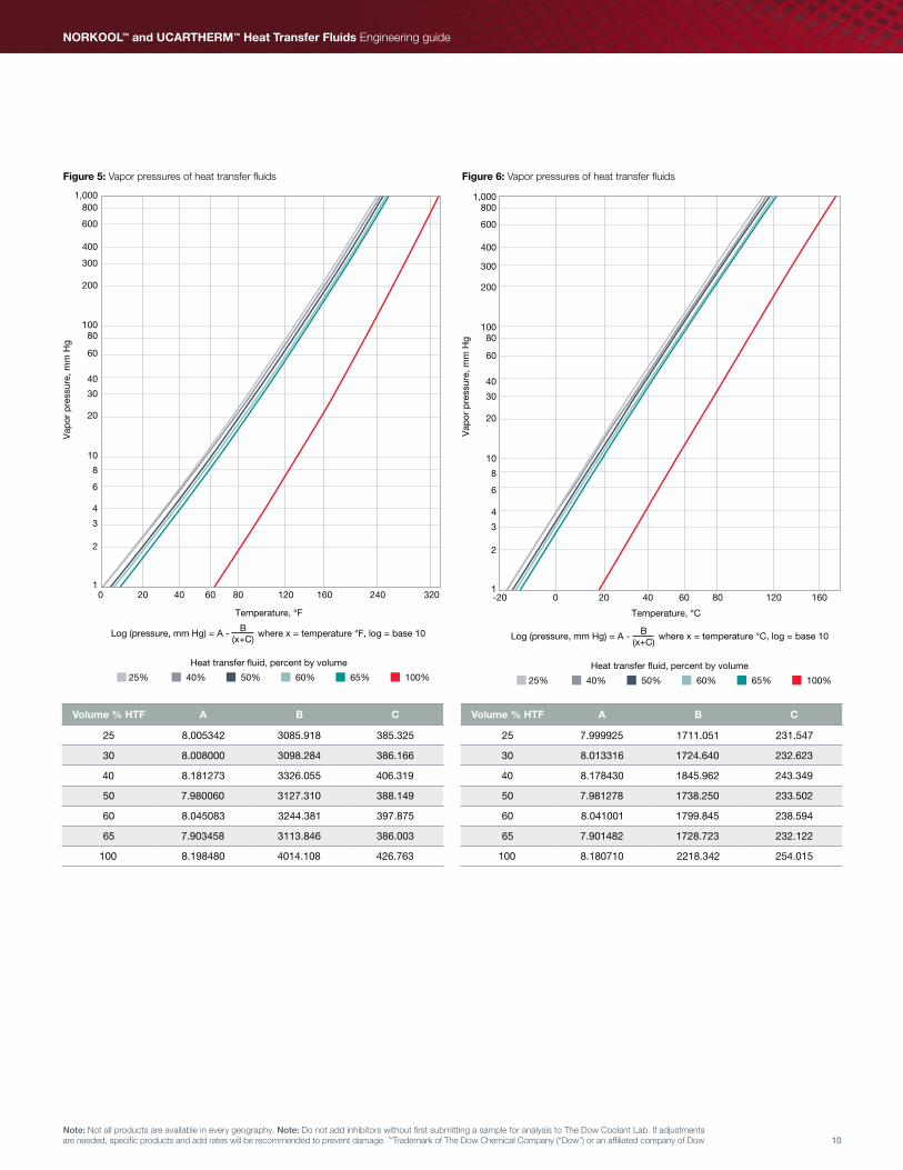
Figure 5: Vapor pressures of heat transfer fluids Figure 6: Vapor pressures of heat transfer fluids
Volume % HTF A B C
25 8.005342 3085.918 385.325
30 8.008000 3098.284 386.166
40 8.181273 3326.055 406.319
50 7.980060 3127.310 388.149
60 8.045083 3244.381 397.875
65 7.903458 3113.846 386.003
100 8.198480 4014.108 426.763
Volume % HTF A B C
25 7.999925 1711.051 231.547
30 8.013316 1724.640 232.623
40 8.178430 1845.962 243.349
50 7.981278 1738.250 233.502
60 8.041001 1799.845 238.594
65 7.901482 1728.723 232.122
100 8.180710 2218.342 254.015
B(x+C)
Log (pressure, mm Hg) = A - where x = temperature °F, log = base 10
Vap
or p
ress
ure,
mm
Hg
1,000800
600
400
300
200
10080
60
40
30
20
10
8
6
4
3
2
10 20 40 60 80 120 160 240 320
Temperature, °F
Heat transfer fluid, percent by volume
25% 40% 50% 60% 65% 100%
B(x+C)
Log (pressure, mm Hg) = A - where x = temperature °C, log = base 10
Heat transfer fluid, percent by volume
25% 40% 50% 60% 65% 100%
Vap
or p
ress
ure,
mm
Hg
1,000800
600
400
300
200
10080
60
40
30
20
10
8
6
4
3
2
1-20 0 20 40 60 80 120 160
Temperature, °C

11Note: Not all products are available in every geography. Note: Do not add inhibitors without first submitting a sample for analysis to The Dow Coolant Lab. If adjustments are needed, specific products and add rates will be recommended to prevent damage. ™Trademark of The Dow Chemical Company (“Dow”) or an affiliated company of Dow
Table 8: Vapor pressures of heat transfer fluids
Temperature °F
Volume % heat transfer fluid Temperature °C25 30 40 50 60 65 100
0 NA NA 0.990 0.838 0.778 0.686 0.062 -18
10 NA 1.539 1.556 1.335 1.232 1.097 0.102 -12
14 1.895 1.843 1.854 1.598 1.472 1.315 0.123 -10
20 2.465 2.398 2.396 2.079 1.910 1.714 0.164 -7
30 3.760 3.657 3.616 3.170 2.901 2.620 0.257 -1
32 4.082 3.970 3.918 3.441 3.146 2.845 0.281 0
40 5.622 5.468 5.359 4.740 4.322 3.927 0.397 4
50 8.252 8.027 7.805 6.958 6.326 5.776 0.601 10
60 11.906 11.581 11.187 10.041 9.106 8.352 0.895 16
68 15.778 15.349 14.757 13.310 12.051 11.087 1.217 20
70 16.902 16.443 15.792 14.259 12.906 11.882 1.312 21
80 23.637 22.998 21.980 19.948 18.026 16.651 1.894 27
86 28.709 27.935 26.630 24.234 21.882 20.247 2.345 30
90 32.592 31.715 30.187 27.518 24.835 23.004 2.696 32
100 44.349 43.163 40.943 37.462 33.777 31.362 3.786 38
104 49.988 48.653 46.097 42.234 38.068 35.376 4.321 40
110 59.601 58.016 54.880 50.373 45.387 42.226 5.250 43
120 79.167 77.076 72.746 66.949 60.296 56.189 7.193 49
122 83.679 81.472 76.865 70.773 63.737 59.412 7.650 50
130 104.003 101.276 95.420 88.007 79.244 73.945 9.744 54
140 135.220 131.700 123.924 114.497 103.094 96.301 13.061 60
150 174.090 169.593 159.437 147.511 132.840 124.187 17.329 66
158 211.666 206.235 193.797 179.452 161.642 151.185 21.576 70
160 222.066 216.377 203.311 188.296 169.620 158.633 22.771 71
170 280.791 273.659 257.080 238.264 214.727 200.930 29.649 77
176 321.945 313.810 294.803 273.306 246.388 230.588 34.591 80
180 352.111 343.246 322.474 299.004 269.621 252.344 38.271 82
190 438.086 427.154 401.448 372.292 335.935 314.415 48.993 88
194 477.084 465.221 437.314 405.556 366.060 342.599 53.960 90
200 541.000 527.622 496.159 460.101 415.492 388.826 62.226 93
210 663.371 647.119 609.015 564.608 510.308 477.431 78.443 99
212 690.419 673.536 633.992 587.720 531.295 497.031 82.090 100
220 807.960 788.352 742.664 688.206 622.606 582.269 98.180 104
230 977.776 954.274 900.012 833.504 754.819 705.566 122.046 110
240 1,176.087 1,148.092 1,084.232 1,003.340 909.599 849.742 150.726 116
248 1,357.612 1,325.549 1,253.261 1,158.931 1,051.597 981.866 177.650 120
250 1,406.419 1,373.268 1,298.768 1,200.783 1,089.824 1,017.412 184.989 121
260 1,672.563 1,633.529 1,547.346 1,429.137 1,298.602 1,211.394 225.690 127
266 1,851.117 1,808.174 1,714.489 1,582.449 1,438.954 1,341.660 253.592 130
270 1,978.579 1,932.862 1,833.978 1,691.941 1,539.275 1,434.707 273.778 132
275 2,147.880 2,098.500 1,992.897 1,837.434 1,672.682 1,558.362 300.917 135
Vapor pressures are reported in millimeters of mercury (mm Hg)Conversions: Atmosphere (atm) = mm Hg / 760 lb/in2 (psi) = (mm Hg / 760) x 14�7

12
NORKOOL™ and UCARTHERM™ Heat Transfer Fluids Engineering guide
Note: Not all products are available in every geography� Note: Do not add inhibitors without first submitting a sample for analysis to The Dow Coolant Lab� If adjustments are needed, specific products and add rates will be recommended to prevent damage� ™Trademark of The Dow Chemical Company (“Dow”) or an affiliated company of Dow
Table 9: Specific gravities of heat transfer fluids
Temperature °F
Volume % heat transfer fluid Temperature °C25 30 40 50 60 65 100
0 NA NA 1.080 1.098 1.114 1.121 1.159 -18
10 NA 1.059 1.078 1.095 1.111 1.118 1.156 -12
14 1.049 1.058 1.077 1.094 1.109 1.117 1.154 -10
20 1.048 1.057 1.075 1.092 1.108 1.115 1.152 -7
30 1.047 1.056 1.073 1.089 1.105 1.111 1.148 -1
32 1.046 1.055 1.073 1.089 1.104 1.111 1.148 0
40 1.045 1.054 1.071 1.087 1.102 1.108 1.145 4
50 1.043 1.052 1.068 1.084 1.098 1.105 1.141 10
60 1.041 1.049 1.065 1.081 1.095 1.101 1.137 16
68 1.040 1.047 1.063 1.078 1.093 1.098 1.134 20
70 1.039 1.047 1.063 1.077 1.092 1.098 1.133 21
80 1.037 1.044 1.060 1.074 1.089 1.094 1.130 27
86 1.035 1.043 1.058 1.072 1.087 1.092 1.127 30
90 1.034 1.042 1.057 1.071 1.086 1.090 1.126 32
100 1.032 1.039 1.054 1.068 1.083 1.087 1.122 38
104 1.031 1.038 1.052 1.066 1.081 1.085 1.120 40
110 1.029 1.036 1.050 1.064 1.079 1.083 1.118 43
120 1.026 1.033 1.047 1.061 1.076 1.079 1.114 49
122 1.026 1.033 1.046 1.060 1.075 1.078 1.113 50
130 1.023 1.030 1.044 1.057 1.073 1.075 1.110 54
140 1.020 1.027 1.040 1.053 1.069 1.071 1.106 60
150 1.016 1.023 1.037 1.050 1.066 1.068 1.102 66
158 1.014 1.020 1.034 1.046 1.063 1.064 1.099 70
160 1.013 1.020 1.033 1.046 1.063 1.064 1.098 71
170 1.009 1.016 1.029 1.042 1.059 1.059 1.094 77
176 1.007 1.014 1.027 1.039 1.057 1.057 1.092 80
180 1.005 1.012 1.025 1.038 1.056 1.055 1.090 82
190 1.001 1.008 1.021 1.034 1.052 1.051 1.086 88
194 1.000 1.007 1.020 1.032 1.051 1.049 1.084 90
200 0.997 1.004 1.017 1.029 1.049 1.047 1.082 93
210 0.993 1.000 1.013 1.025 1.045 1.043 1.078 99
212 0.992 0.999 1.012 1.024 1.044 1.042 1.077 100
220 0.988 0.996 1.009 1.021 1.041 1.038 1.073 104
230 0.984 0.991 1.004 1.016 1.038 1.034 1.069 110
240 0.979 0.987 1.000 1.012 1.034 1.030 1.065 116
248 0.975 0.983 0.996 1.008 1.031 1.026 1.062 120
250 0.974 0.982 0.995 1.007 1.031 1.025 1.061 121
260 0.969 0.977 0.991 1.002 1.027 1.020 1.056 127
266 0.966 0.974 0.988 1.000 1.025 1.018 1.054 130
270 0.963 0.972 0.986 0.998 1.023 1.016 1.052 132
275 0.961 0.969 0.984 0.995 1.021 1.014 1.050 135
Conversions: Density, t(°F) = specific gravity, t/68°F x water density, 68°F density, t(°C) = specific gravity, t/20°C x water density, 20°C g/cm3 = specific gravity x 0�99823 g/cm3 lb/gal = specific gravity x 8�32 lb/gal lb/ft3 = specific gravity x 62�32 lb/ft3 kg/m = specific gravity x 998�23 kg/m
13Note: Not all products are available in every geography. Note: Do not add inhibitors without first submitting a sample for analysis to The Dow Coolant Lab. If adjustments are needed, specific products and add rates will be recommended to prevent damage. ™Trademark of The Dow Chemical Company (“Dow”) or an affiliated company of Dow
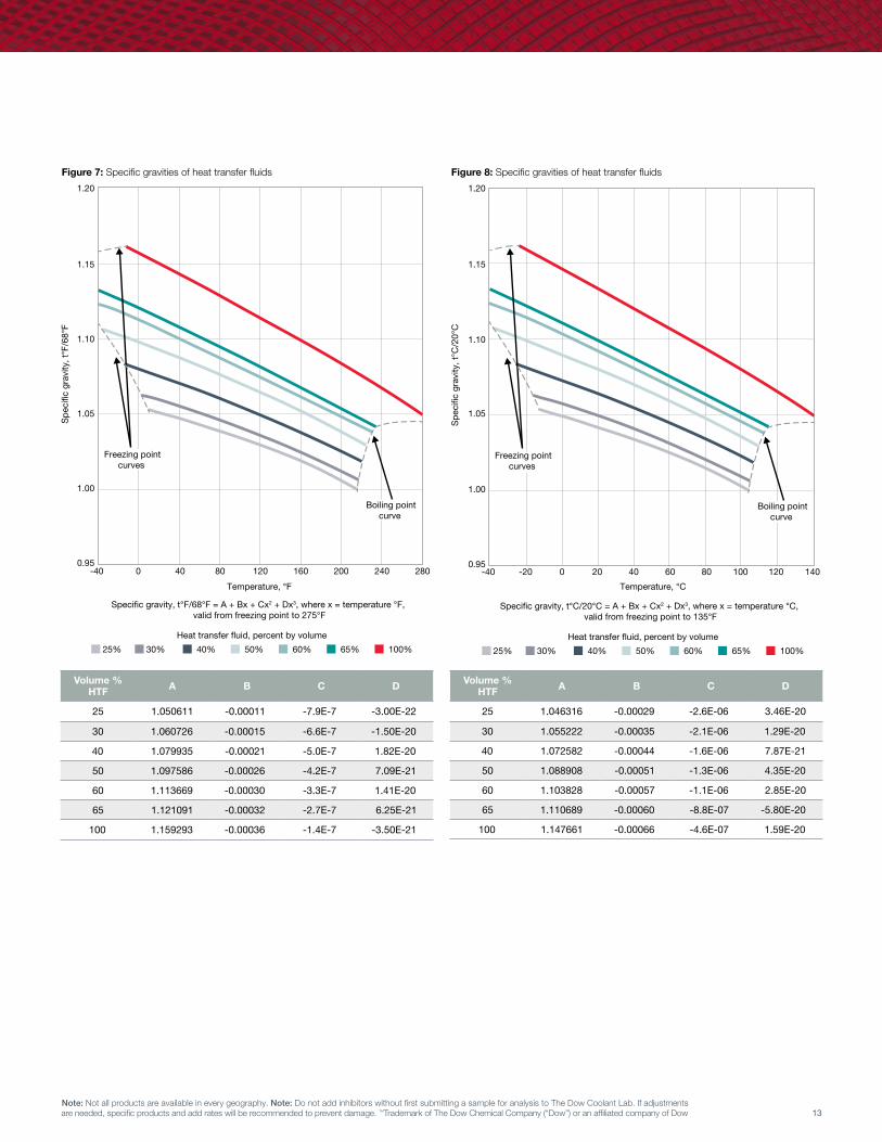
Figure 7: Specific gravities of heat transfer fluids
Volume % HTF A B C D
25 1.050611 -0.00011 -7.9E-7 -3.00E-22
30 1.060726 -0.00015 -6.6E-7 -1.50E-20
40 1.079935 -0.00021 -5.0E-7 1.82E-20
50 1.097586 -0.00026 -4.2E-7 7.09E-21
60 1.113669 -0.00030 -3.3E-7 1.41E-20
65 1.121091 -0.00032 -2.7E-7 6.25E-21
100 1.159293 -0.00036 -1.4E-7 -3.50E-21
30% 25% 40% 50% 60% 65% 100%
Temperature, °F
Specific gravity, t°F/68°F = A + Bx + Cx2 + Dx3, where x = temperature °F, valid from freezing point to 275°F
Spe
cific
gra
vity
, t°F
/68°
F
-40 0 40 80 120 160 200 240 280
1.20
1.15
1.10
1.05
1.00
0.95
Boiling pointcurve
Freezing pointcurves
Heat transfer fluid, percent by volume
Spe
cific
gra
vity
, t°C
/20°
C
1.20
1.15
1.10
1.05
1.00
0.95
Temperature, °C
-40 -20 0 20 40 60 80 100 120 140
30% 25% 40% 50% 60% 65% 100%
Specific gravity, t°C/20°C = A + Bx + Cx2 + Dx3, where x = temperature °C, valid from freezing point to 135°F
Heat transfer fluid, percent by volume
Boiling pointcurve
Freezing pointcurves
Figure 8: Specific gravities of heat transfer fluids
Volume % HTF A B C D
25 1.046316 -0.00029 -2.6E-06 3.46E-20
30 1.055222 -0.00035 -2.1E-06 1.29E-20
40 1.072582 -0.00044 -1.6E-06 7.87E-21
50 1.088908 -0.00051 -1.3E-06 4.35E-20
60 1.103828 -0.00057 -1.1E-06 2.85E-20
65 1.110689 -0.00060 -8.8E-07 -5.80E-20
100 1.147661 -0.00066 -4.6E-07 1.59E-20
14
NORKOOL™ and UCARTHERM™ Heat Transfer Fluids Engineering guide
Note: Not all products are available in every geography� Note: Do not add inhibitors without first submitting a sample for analysis to The Dow Coolant Lab� If adjustments are needed, specific products and add rates will be recommended to prevent damage� ™Trademark of The Dow Chemical Company (“Dow”) or an affiliated company of Dow
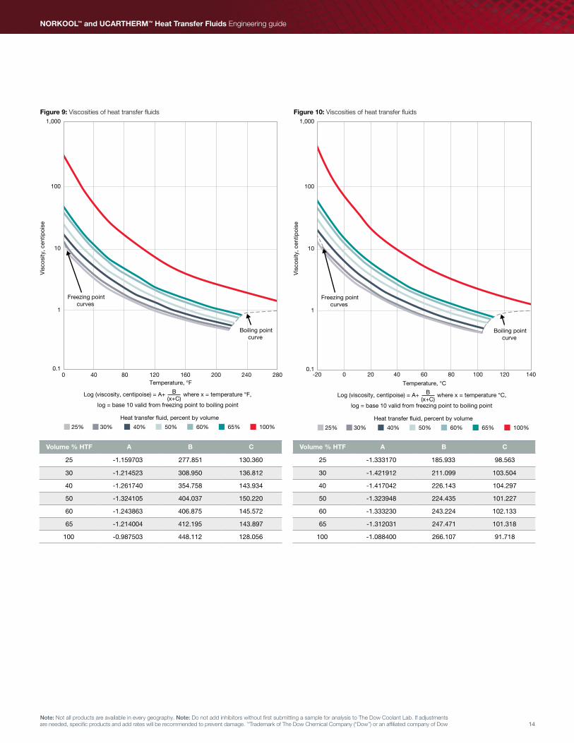
Figure 9: Viscosities of heat transfer fluids
Volume % HTF A B C
25 -1.159703 277.851 130.360
30 -1.214523 308.950 136.812
40 -1.261740 354.758 143.934
50 -1.324105 404.037 150.220
60 -1.243863 406.875 145.572
65 -1.214004 412.195 143.897
100 -0.987503 448.112 128.056
Volume % HTF A B C
25 -1.333170 185.933 98.563
30 -1.421912 211.099 103.504
40 -1.417042 226.143 104.297
50 -1.323948 224.435 101.227
60 -1.333230 243.224 102.133
65 -1.312031 247.471 101.318
100 -1.088400 266.107 91.718
30% 25% 40% 50% 60% 65% 100%
Log (viscosity, centipoise) = A+ where x = temperature °F, B(x+C)
Heat transfer fluid, percent by volume
Boiling pointcurve
Freezing pointcurves
0 40 80 120 160 200 240 280Temperature, °F
1,000
100
10
1
0.1
Vis
cosi
ty, c
entip
oise
log = base 10 valid from freezing point to boiling point
30% 25% 40% 50% 60% 65% 100%
Log (viscosity, centipoise) = A+ where x = temperature °C, B(x+C)
Heat transfer fluid, percent by volume
Boiling pointcurve
Freezing pointcurves
-20 0 20 40 8060 100 120 140
Temperature, °C
1,000
100
10
1
0.1
Vis
cosi
ty, c
entip
oise
log = base 10 valid from freezing point to boiling point
Figure 10: Viscosities of heat transfer fluids

15Note: Not all products are available in every geography. Note: Do not add inhibitors without first submitting a sample for analysis to The Dow Coolant Lab. If adjustments are needed, specific products and add rates will be recommended to prevent damage. ™Trademark of The Dow Chemical Company (“Dow”) or an affiliated company of Dow
Table 10: Viscosities of heat transfer fluids
Temperature °F
Volume % heat transfer fluid Temperature °C25 30 40 50 60 65 100
0 NA NA 15.958 23.202 35.575 44.721 324.965 -18
10 NA 7.760 11.037 15.764 23.523 29.133 181.286 -12
14 5.821 6.824 9.649 13.685 20.227 24.919 146.882 -10
20 4.878 5.697 7.985 11.208 16.350 19.997 109.429 -7
30 3.741 4.341 5.996 8.276 11.846 14.333 70.411 -1
32 3.561 4.127 5.684 7.820 11.155 13.471 64.895 0
40 2.960 3.410 4.645 6.309 8.885 10.652 47.746 4
50 2.403 2.750 3.694 4.942 6.864 8.163 33.821 10
60 1.995 2.266 3.005 3.962 5.437 6.421 24.852 16
68 1.742 1.968 2.583 3.368 4.584 5.386 19.867 20
70 1.687 1.903 2.492 3.240 4.401 5.165 18.839 21
80 1.449 1.623 2.101 2.697 3.630 4.236 14.666 27
86 1.332 1.486 1.910 2.434 3.259 3.793 12.762 30
90 1.262 1.405 1.798 2.280 3.043 3.534 11.682 32
100 1.113 1.231 1.558 1.953 2.588 2.993 9.493 38
104 1.061 1.171 1.476 1.842 2.435 2.810 8.781 40
110 0.991 1.090 1.366 1.693 2.229 2.567 7.850 43
120 0.891 0.974 1.209 1.483 1.942 2.228 6.592 49
122 0.874 0.953 1.181 1.446 1.891 2.169 6.376 50
130 0.808 0.878 1.080 1.311 1.708 1.954 5.610 54
140 0.738 0.797 0.972 1.170 1.517 1.729 4.833 60
150 0.678 0.729 0.881 1.051 1.357 1.544 4.208 66
158 0.637 0.681 0.819 0.970 1.249 1.417 3.793 70
160 0.627 0.670 0.804 0.951 1.224 1.388 3.699 71
170 0.583 0.620 0.738 0.866 1.110 1.256 3.281 77
176 0.559 0.593 0.703 0.821 1.051 1.187 3.064 80
180 0.544 0.576 0.681 0.793 1.014 1.144 2.932 82
190 0.510 0.538 0.632 0.730 0.930 1.048 2.639 88
194 0.498 0.524 0.614 0.707 0.900 1.014 2.535 90
200 0.480 0.504 0.588 0.675 0.858 0.965 2.390 93
210 0.454 0.475 0.550 0.627 0.795 0.893 2.178 99
212 0.449 0.469 0.543 0.619 0.783 0.879 2.139 100
220 0.430 0.448 0.516 0.585 0.740 0.829 1.995 104
230 0.409 0.424 0.486 0.548 0.691 0.773 1.837 110
240 0.390 0.403 0.459 0.514 0.648 0.724 1.698 116
248 0.376 0.388 0.440 0.490 0.617 0.688 1.600 120
250 0.372 0.384 0.435 0.485 0.609 0.680 1.577 121
260 0.357 0.366 0.414 0.458 0.575 0.641 1.470 127
266 0.348 0.357 0.401 0.443 0.556 0.619 1.411 130
270 0.342 0.351 0.394 0.434 0.544 0.605 1.375 132
275 0.336 0.343 0.385 0.423 0.529 0.589 1.331 135
Viscosity values are reported in centipoise (cP)Conversions: kg/m - sec = cP x 0�001 lb/ft - hr = cP x 2�4191 centistokes (cSt) = cP g/m - density (g/cm3)

16
NORKOOL™ and UCARTHERM™ Heat Transfer Fluids Engineering guide
Note: Not all products are available in every geography� Note: Do not add inhibitors without first submitting a sample for analysis to The Dow Coolant Lab� If adjustments are needed, specific products and add rates will be recommended to prevent damage� ™Trademark of The Dow Chemical Company (“Dow”) or an affiliated company of Dow
Table 11: Specific heats of heat transfer fluids
Temperature °F
Volume % heat transfer fluid Temperature °C25 30 40 50 60 65 100
0 NA NA 0.805 0.757 0.710 0.687 0.533 -18
10 NA 0.857 0.810 0.763 0.716 0.693 0.539 -12
14 0.883 0.859 0.812 0.765 0.719 0.696 0.542 -10
20 0.885 0.862 0.815 0.768 0.722 0.700 0.546 -7
30 0.889 0.866 0.820 0.774 0.729 0.706 0.552 -1
32 0.890 0.866 0.821 0.775 0.730 0.708 0.553 0
40 0.892 0.870 0.825 0.780 0.735 0.713 0.559 4
50 0.896 0.874 0.830 0.785 0.741 0.719 0.565 10
60 0.900 0.878 0.835 0.791 0.747 0.725 0.571 16
68 0.903 0.881 0.839 0.769 0.752 0.730 0.576 20
70 0.903 0.882 0.840 0.797 0.753 0.732 0.578 21
80 0.907 0.886 0.845 0.802 0.760 0.738 0.584 27
86 0.909 0.889 0.848 0.806 0.763 0.742 0.588 30
90 0.911 0.890 0.850 0.808 0.766 0.745 0.590 32
100 0.914 0.895 0.855 0.814 0.772 0.751 0.597 38
104 0.916 0.896 0.857 0.816 0.775 0.753 0.599 40
110 0.918 0.899 0.860 0.819 0.778 0.757 0.603 43
120 0.921 0.903 0.865 0.825 0.784 0.764 0.609 49
122 0.922 0.904 0.866 0.826 0.786 0.765 0.611 50
130 0.925 0.907 0.870 0.831 0.791 0.770 0.616 54
140 0.929 0.911 0.875 0.837 0.797 0.776 0.622 60
150 0.932 0.915 0.880 0.842 0.803 0.783 0.629 66
158 0.935 0.918 0.884 0.847 0.808 0.788 0.634 70
160 0.936 0.919 0.885 0.848 0.809 0.789 0.635 71
170 0.939 0.923 0.890 0.854 0.815 0.796 0.641 77
176 0.942 0.926 0.893 0.857 0.819 0.799 0.645 80
180 0.943 0.927 0.895 0.859 0.822 0.802 0.648 82
190 0.947 0.932 0.900 0.865 0.828 0.808 0.654 88
194 0.948 0.933 0.902 0.867 0.830 0.811 0.657 90
200 0.950 0.936 0.905 0.871 0.834 0.815 0.660 93
210 0.954 0.940 0.910 0.876 0.840 0.821 0.667 99
212 0.955 0.941 0.911 0.878 0.842 0.822 0.668 100
220 0.958 0.944 0.915 0.882 0.846 0.828 0.673 104
230 0.961 0.948 0.920 0.888 0.853 0.834 0.679 110
240 0.965 0.952 0.925 0.893 0.859 0.840 0.686 116
248 0.968 0.956 0.929 0.898 0.864 0.845 0.691 120
250 0.968 0.956 0.930 0.899 0.865 0.847 0.692 121
260 0.972 0.960 0.935 0.905 0.871 0.853 0.699 127
266 0.974 0.963 0.938 0.908 0.875 0.857 0.702 130
270 0.976 0.965 0.940 0.911 0.877 0.859 0.705 132
275 0.977 0.967 0.942 0.913 0.881 0.863 0.708 135
Specific heat values are reported in Btu/lb-°F = cal/g-°CJoule/kg-°C = 4,184 x cal/g-°C
17Note: Not all products are available in every geography. Note: Do not add inhibitors without first submitting a sample for analysis to The Dow Coolant Lab. If adjustments are needed, specific products and add rates will be recommended to prevent damage. ™Trademark of The Dow Chemical Company (“Dow”) or an affiliated company of Dow
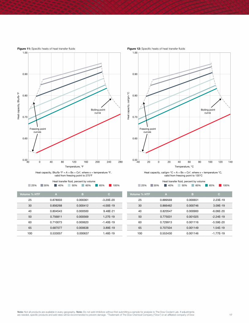
Figure 11: Specific heats of heat transfer fluids
Volume % HTF A B C
25 0.878003 0.000361 -3.20E-20
30 0.856268 0.000412 -4.00E-19
40 0.804543 0.000500 9.48E-21
50 0.756811 0.000569 1.27E-19
60 0.710073 0.000620 -1.40E-19
65 0.687077 0.000638 3.89E-19
100 0.533057 0.000637 1.46E-19
Volume % HTF A B C
25 0.889569 0.000651 2.23E-19
30 0.866462 0.000746 3.09E-19
40 0.820547 0.000900 -6.06E-20
50 0.775031 0.001025 -2.24E-19
60 0.729913 0.001116 -5.59E-20
65 0.707504 0.001149 1.54E-19
100 0.553430 0.001146 -1.77E-19
Figure 12: Specific heats of heat transfer fluids
30% 25% 40% 50% 60% 65% 100%
Heat transfer fluid, percent by volume
Boiling pointcurve
Freezing pointcurves
40 0 40 80 160120 200 240 280
Temperature, °F
Hea
t ca
pac
ity, B
tu/lb
-°F
1.00
0.90
0.80
0.70
0.60
0.50
Heat capacity, Btu/lb-°F = A + Bx + Cx2, where x = temperature °F,valid from freezing point to 275°F
30% 25% 40% 50% 60% 65% 100%
Heat transfer fluid, percent by volume
Boiling pointcurve
Freezing pointcurves
-40 20 0 20 806040 100 120 140
Temperature, °C
Hea
t cap
acity
, cal
/gm
-°C
1.00
0.90
0.80
0.70
0.60
0.50
Heat capacity, cal/gm-°C = A + Bx + Cx2, where x = temperature °C, valid from freezing point to 135°C

18
NORKOOL™ and UCARTHERM™ Heat Transfer Fluids Engineering guide
Note: Not all products are available in every geography� Note: Do not add inhibitors without first submitting a sample for analysis to The Dow Coolant Lab� If adjustments are needed, specific products and add rates will be recommended to prevent damage� ™Trademark of The Dow Chemical Company (“Dow”) or an affiliated company of Dow
Volume % HTF A B
25 0.25559571 3.32E-4
30 0.24583404 3.04E-4
40 0.22750438 2.51E-4
50 0.21076690 2.04E-4
60 0.19561980 1.61E-4
65 0.18864510 1.42E-4
100 0.15094955 4.26E-5
Volume % HTF A B
25 0.00110045 2.74E-6
30 0.00105638 2.26E-6
40 0.00097367 1.87E-6
50 0.00089822 1.52E-6
60 0.00083000 1.20E-6
65 0.00079862 1.06E-6
100 0.00062963 3.17E-6
Figure 13: Thermal conductivities of heat transfer fluids Figure 14: Thermal conductivities of heat transfer fluids
Boiling pointcurve Freezing point
curves
40 0 40 80 160120 200 240 280
Temperature, °F
Ther
mal
con
duct
ivity
, Btu
/hr-
ft-°
F
0.40
0.35
0.30
0.25
0.20
0.15
0.10
30% 25% 40% 50% 60% 65% 100%
Heat transfer fluid, percent by volume
Thermal conductivity, Btu/hr-ft-°F = A + Bx, where x = temperature °F, valid from freezing point to 275°F
30% 25% 40% 50% 60% 65% 100%
Heat transfer fluid, percent by volume
Boiling pointcurve
Freezing pointcurves
-40 20 0 20 806040 100 120 140
Temperature, °C
Ther
mal
con
duct
ivity
x 1
04 , c
al/s
ec-c
m-°
C
Thermal conductivity, cal/sec-cm-°C = A + Bx, where x = temperature °C, valid from freezing point to 135°C
16.0
15.0
14.0
13.0
12.0
11.0
10.0
9.0
8.0
7.0
6.0

19Note: Not all products are available in every geography. Note: Do not add inhibitors without first submitting a sample for analysis to The Dow Coolant Lab. If adjustments are needed, specific products and add rates will be recommended to prevent damage. ™Trademark of The Dow Chemical Company (“Dow”) or an affiliated company of Dow
Table 12: Thermal conductivities of heat transfer fluids
Temperature °F
Volume % heat transfer fluid Temperature °C25 30 40 50 60 65 100
0 NA NA 0.2275 0.2108 0.1956 0.1886 0.1509 -18
10 NA 0.2489 0.2300 0.2128 0.1977 0.1901 0.1514 -12
14 0.2602 0.2501 0.2310 0.2136 0.1985 0.1906 0.1515 -10
20 0.2622 0.2519 0.2325 0.2148 0.1997 0.1915 0.1518 -7
30 0.2656 0.2550 0.2350 0.2169 0.2017 0.1929 0.1522 -1
32 0.2662 0.2556 0.2355 0.2173 0.2021 0.1932 0.1523 0
40 0.2689 0.2580 0.2375 0.2189 0.2038 0.1943 0.1527 4
50 0.2722 0.2610 0.2401 0.2210 0.2058 0.1957 0.1531 10
60 0.2755 0.2641 0.2426 0.2230 0.2079 0.1972 0.1535 16
68 0.2782 0.2665 0.2446 0.2246 0.2095 0.1983 0.1538 20
70 0.2788 0.2671 0.2451 0.2250 0.2099 0.1986 0.1539 21
80 0.2822 0.2702 0.2476 0.2271 0.2119 0.2000 0.1544 27
86 0.2841 0.2720 0.2491 0.2283 0.2132 0.2009 0.1546 30
90 0.2855 0.2732 0.2501 0.2291 0.2140 0.2014 0.1548 32
100 0.2888 0.2762 0.2526 0.2312 0.2160 0.2028 0.1552 38
104 0.2901 0.2775 0.2536 0.2320 0.2168 0.2034 0.1554 40
110 0.2921 0.2793 0.2551 0.2332 0.2181 0.2043 0.1556 43
120 0.2954 0.2823 0.2576 0.2352 0.2201 0.2057 0.1561 49
122 0.2961 0.2829 0.2581 0.2357 0.2205 0.2060 0.1561 50
130 0.2988 0.2854 0.2601 0.2373 0.2221 0.2071 0.1565 54
140 0.3021 0.2884 0.2626 0.2393 0.2242 0.2085 0.1569 60
150 0.3054 0.2914 0.2652 0.2414 0.2262 0.2099 0.1573 66
158 0.3081 0.2939 0.2672 0.2430 0.2279 0.2111 0.1577 70
160 0.3087 0.2945 0.2677 0.2434 0.2283 0.2114 0.1578 71
170 0.3120 0.2975 0.2702 0.2454 0.2303 0.2128 0.1582 77
176 0.3140 0.2993 0.2717 0.2467 0.2315 0.2136 0.1584 80
180 0.3154 0.3006 0.2727 0.2475 0.2323 0.2142 0.1586 82
190 0.3187 0.3036 0.2752 0.2495 0.2344 0.2156 0.1590 88
194 0.3200 0.3048 0.2762 0.2503 0.2352 0.2162 0.1592 90
200 0.3220 0.3066 0.2777 0.2516 0.2364 0.2170 0.1595 93
210 0.3253 0.3097 0.2802 0.2536 0.2385 0.2185 0.1599 99
212 0.3260 0.3103 0.2807 0.2540 0.2389 0.2187 0.1600 100
220 0.3286 0.3127 0.2827 0.2556 0.2405 0.2199 0.1603 104
230 0.3320 0.3158 0.2852 0.2577 0.2425 0.2213 0.1607 110
240 0.3353 0.3188 0.2877 0.2597 0.2446 0.2227 0.1612 116
248 0.3379 0.3212 0.2898 0.2614 0.2462 0.2239 0.1615 120
250 0.3386 0.3218 0.2903 0.2618 0.2466 0.2241 0.1616 121
260 0.3419 0.3249 0.2928 0.2638 0.2487 0.2256 0.1620 127
266 0.3439 0.3267 0.2943 0.2650 0.2499 0.2264 0.1623 130
270 0.3452 0.3279 0.2953 0.2658 0.2507 0.2270 0.1625 132
275 0.3469 0.3294 0.2965 0.2669 0.2517 0.2277 0.1627 135
Thermal conductivities are reported in Btu/hr-ft - °FConversions: cal/sec cm °C = 0�00413 x Btu/hr-ft - °F J/sec cm °C = 0�0173 x Btu/hr-ft - °F

20
NORKOOL™ and UCARTHERM™ Heat Transfer Fluids Engineering guide
Note: Not all products are available in every geography� Note: Do not add inhibitors without first submitting a sample for analysis to The Dow Coolant Lab� If adjustments are needed, specific products and add rates will be recommended to prevent damage� ™Trademark of The Dow Chemical Company (“Dow”) or an affiliated company of Dow
Figure 15: Electrical conductivities of heat transfer fluids
A B C D
25°C (77°F) 2.027 0.1902 -0.003606 1.633E-5
65°C (150°F) 4.519 0.3168 -0.004901 1.698E-5
Note: The quality of the water used for dilution can significantly affect electrical conductivity�
Electrical conductivity, millimhos/cm = A + Bx + Cx2 + Dx3, where x = vol% HTF;equation is valid for 25 to 100% HTF, in solution with deionized water
Heat transfer fluid, percent by volume
Ele
ctric
al c
ondu
ctiv
ity, m
illim
hos/
cm
0 10 20 30 40 50 60 70 80 90 100
65°C
25°C
100
60
40
20
10
1
21Note: Not all products are available in every geography. Note: Do not add inhibitors without first submitting a sample for analysis to The Dow Coolant Lab. If adjustments are needed, specific products and add rates will be recommended to prevent damage. ™Trademark of The Dow Chemical Company (“Dow”) or an affiliated company of Dow
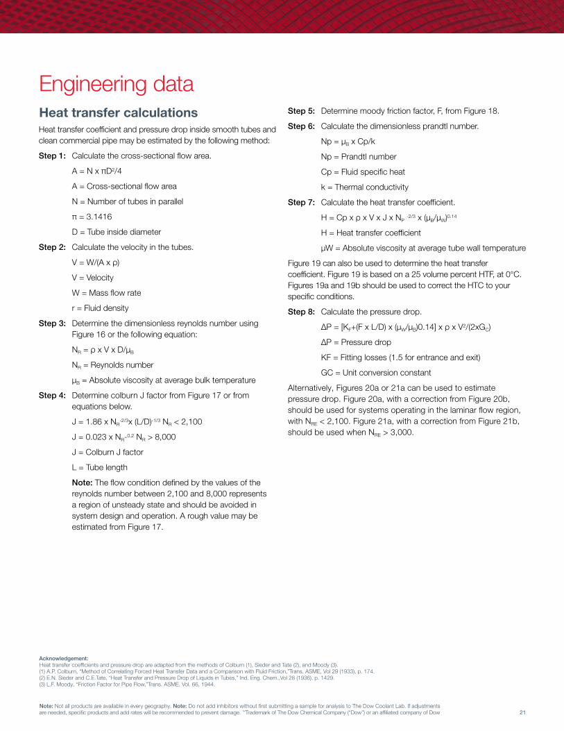
Engineering dataStep 5: Determine moody friction factor, F, from Figure 18�
Step 6: Calculate the dimensionless prandtl number�
Np = μB x Cp/k
Np = Prandtl number
Cp = Fluid specific heat
k = Thermal conductivity
Step 7: Calculate the heat transfer coefficient�
H = Cp x ρ x V x J x NP -2/3 x (μB/μW)0�14
H = Heat transfer coefficient
μW = Absolute viscosity at average tube wall temperature
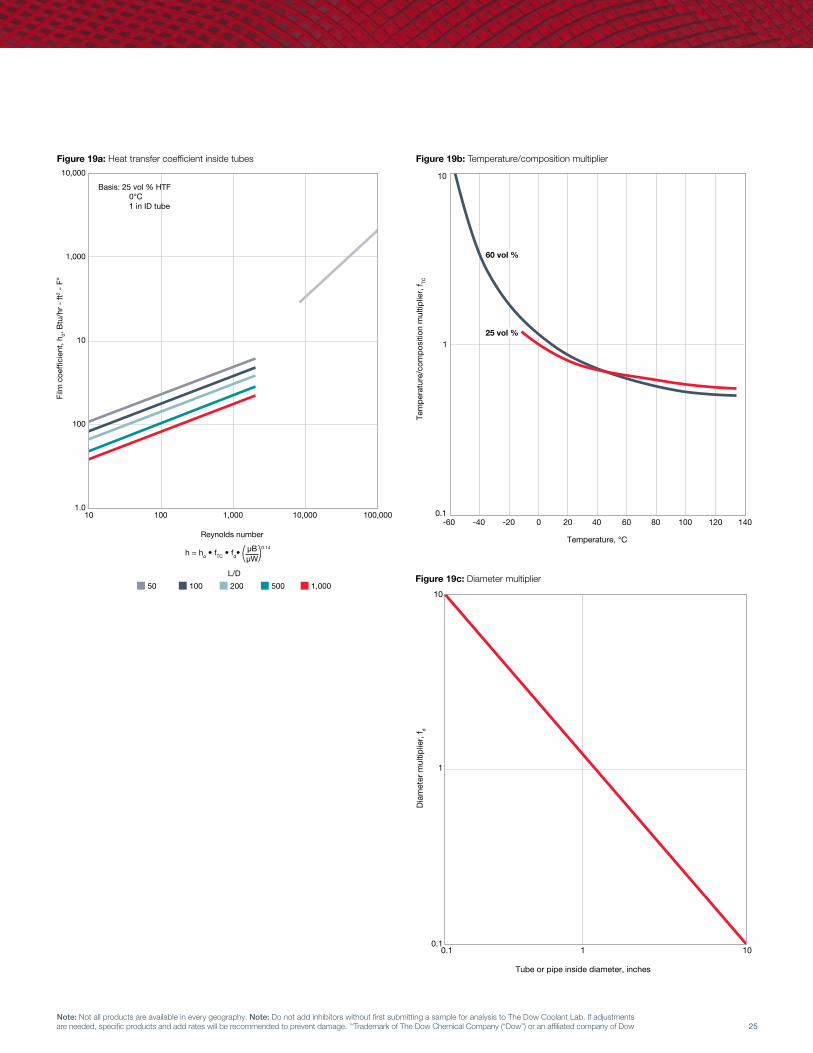
Figure 19 can also be used to determine the heat transfer coefficient� Figure 19 is based on a 25 volume percent HTF, at 0°C� Figures 19a and 19b should be used to correct the HTC to your specific conditions�
Step 8: Calculate the pressure drop�
ΔP = [KF+(F x L/D) x (μW/μB)0�14] x ρ x V2/(2xGC)
ΔP = Pressure drop
KF = Fitting losses (1�5 for entrance and exit)
GC = Unit conversion constant
Alternatively, Figures 20a or 21a can be used to estimate pressure drop� Figure 20a, with a correction from Figure 20b, should be used for systems operating in the laminar flow region, with NRE < 2,100� Figure 21a, with a correction from Figure 21b, should be used when NRE > 3,000�
Acknowledgement:Heat transfer coefficients and pressure drop are adapted from the methods of Colburn (1), Sieder and Tate (2), and Moody (3)� (1) A�P� Colburn, “Method of Correlating Forced Heat Transfer Data and a Comparison with Fluid Friction,”Trans� ASME, Vol 29 (1933), p� 174�(2) E�N� Sieder and C�E�Tate, “Heat Transfer and Pressure Drop of Liquids in Tubes,” Ind� Eng� Chem�,Vol 28 (1936), p� 1429�(3) L�F� Moody, “Friction Factor for Pipe Flow,”Trans� ASME, Vol� 66, 1944�
Heat transfer calculationsHeat transfer coefficient and pressure drop inside smooth tubes and clean commercial pipe may be estimated by the following method:
Step 1: Calculate the cross-sectional flow area�
A = N x πD2/4
A = Cross-sectional flow area
N = Number of tubes in parallel
π = 3�1416
D = Tube inside diameter
Step 2: Calculate the velocity in the tubes�
V = W/(A x ρ)
V = Velocity
W = Mass flow rate
r = Fluid density
Step 3: Determine the dimensionless reynolds number using Figure 16 or the following equation:
NR = ρ x V x D/μB
NR = Reynolds number
μB = Absolute viscosity at average bulk temperature
Step 4: Determine colburn J factor from Figure 17 or from equations below�
J = 1�86 x NR-2/3x (L/D)-1/3 NR < 2,100
J = 0�023 x NR-0�2 NR > 8,000
J = Colburn J factor
L = Tube length
Note: The flow condition defined by the values of the reynolds number between 2,100 and 8,000 represents a region of unsteady state and should be avoided in system design and operation� A rough value may be estimated from Figure 17�

22
NORKOOL™ and UCARTHERM™ Heat Transfer Fluids Engineering guide
Note: Not all products are available in every geography� Note: Do not add inhibitors without first submitting a sample for analysis to The Dow Coolant Lab� If adjustments are needed, specific products and add rates will be recommended to prevent damage� ™Trademark of The Dow Chemical Company (“Dow”) or an affiliated company of Dow
30°F 25°F
Organics @180°F200,000 lb/hr30% UCARTHEM™ HTF @15°F
Step 1: Area for flow
A =
N x πD2 =
357 x π x 0�4952 4 4
A =
68�7 =
in2 • ft2 = 0�477 ft2
144 in2
Step 2: Velocity
ρ = 1�057 x 62�32 = 66�1 lb
(Table 8: 20°F, 30%)
ft3
V =
W =
200,000 lb/hr Axρ 0�477ft2 x 66�1 lb/ft3
V = 6,343 ft/hr x
1 hr = 1�76 ft/sec
3,600 sec
Step 3: Reynolds number
μB = 5�697cP x 2�4191 lb/(ft • hr • cP) (Table 9: 20°F, 30%)
= 13�78 lb/(ft • hr)
D = 0�495 in = 0�04125 ft
NR =
ρVD =
66�1 lb/ft2 x 6,343 ft/hr x 0�04125 ft μB 13�78 lb/(ft • hr)
NR =1,255
Step 4: J-factor
Because NR < 2,100, use J = 1�86NR
-2/3 L -1/3
D
J = 1�86 x (1255)-2/3 x
16 -1/3
= 0�0022
�04125
Step 5: Moody friction factor
From Figure 18 @ NR = 1,248ρ F = 0�051
( ) ( )
Step 6: Prandtl number
k = 0�2519 Btu/(hr • ft • °F) (Table 11: 20°F, 30%)
Cp = 0�862 Btu/(lb • °F) (Table 10: 20°F, 30%)
Np =
13�78 lb/(hr • ft) x 0�884 Btu/(lb • °F) 0�2519 Btu/(hr • ft • °F)
= 48�36
Step 7: Heat transfer coefficient: Assume average tube wall temperature equals average process temperature�
TW =
180 + 30 = 105°F
2
μW = 1�156 cP (Table 9: 105°F, 30%)
H = Cp x ρ x V x J x Np
-2/3 x μB 0�14
μW
H = 0�862
Btu x 66�1
lb x 6,343
ft lb • °F ft2 hr
x 0�0022 x (48�36)-2/3 x
5�697 0�14 1�156
H = 79�3
Btu (hr • ft2 • °F)
Step 8: Pressure drop
KF = 1�5 for entrance and exit losses
gC = 32�2
lbmass • ft lbforce • sec2
ΔP = KF +
F x L x μW 0�14
x ρ x V2
D μB 2gc
ΔP = 1�5 +
0�051 x 16 ft 1�156 0�14 0�04125 ft 5�697
x 66�1 lbmass /ft3 x (1�76 ft/sec)2
2 x 32�2 lbmass • ft/(lbforce • sec2)
ΔP = 55�0
lbforce = 0�38
lbforce = 0�38 psi
ft2 in2
( )
( )
( ) [ ] ( ) ( )
Example problem200,000 lb/hr of 30% UCARTHERM™ HTF by volume is used to cool an organic liquid from 180°F to 30°F� The UCARTHERM™ HTF enters the tube heat exchanger at 15°F and exits at 25°F� The single pass tubeside heat exchanger contains 357, 5⁄8 inch, 16 BWG (ID = 0�495 inches) tubes, 16 feet long� Calculate the heat transfer coefficient and the pressure drop inside the tubes�

23Note: Not all products are available in every geography. Note: Do not add inhibitors without first submitting a sample for analysis to The Dow Coolant Lab. If adjustments are needed, specific products and add rates will be recommended to prevent damage. ™Trademark of The Dow Chemical Company (“Dow”) or an affiliated company of Dow
Figure 16a: Reynolds number Figure 16b: Temperature/composition multiplier
0.5 inch ID 1.0 inch ID 2.0 inch ID 5.0 inch ID 10.0 inch ID
Heat transfer fluid, percent by volume
Flow rate, gallons per minute To calculate, see HTF calculations page 21, step 3
Rey
nold
s nu
mbe
r
0.1 1 10 100 1000 10000
1,000,000
100,000
10,000
1,000
100
10
Temperature, °C
-60 -40 -20 0 20 40 60 80 100 120 140
100
10
1
0.1
0.01
0.001
0.0001
Tem
pera
ture
/com
posi
tion
mul
tiplie
r, f TC
25% volume 40% volume 60% volume
Heat transfer fluid, percent by volume

24
NORKOOL™ and UCARTHERM™ Heat Transfer Fluids Engineering guide
Note: Not all products are available in every geography� Note: Do not add inhibitors without first submitting a sample for analysis to The Dow Coolant Lab� If adjustments are needed, specific products and add rates will be recommended to prevent damage� ™Trademark of The Dow Chemical Company (“Dow”) or an affiliated company of Dow
Figure 17: Colburn J factor: Transfer inside tubes Figure 18: Moody friction factor: Pressure drop inside tubes
50 100 200 500 1,000
L/D
Col
burn
J fa
ctor
, dim
ensi
onle
ss
10 100 1,000 10,000 100,000
Reynolds number, dimensionless
0.1
0.01
0.00110 100 1,000 10,000 100,000
Reynolds number, dimensionless
Moo
dy fr
ictio
n fa
ctor
, dim
ensi
onle
ss
10
1
0.1
0.01
Pipe
Tube
25Note: Not all products are available in every geography. Note: Do not add inhibitors without first submitting a sample for analysis to The Dow Coolant Lab. If adjustments are needed, specific products and add rates will be recommended to prevent damage. ™Trademark of The Dow Chemical Company (“Dow”) or an affiliated company of Dow
Figure 19a: Heat transfer coefficient inside tubes
50 100 200 500 1,000
L/D
10 100 1,000 10,000 100,000
Film
coe
ffici
ent,
h 0, B
tu/h
r -
ft2
- F°
10,000
1,000
10
100
1.0
Reynolds number
h = ho • fTC • fd•μB 0.14
μW
Basis: 25 vol % HTF 0°C 1 in ID tube
Tem
pera
ture
/com
posi
tion
mul
tiplie
r, f TC
Temperature, °C
10
1
0.1-60 -40 -20 0 20 40 60 80 100 120 140
60 vol %
25 vol %
10
1
0.10.1 1 10
Tube or pipe inside diameter, inches
Dia
met
er m
ultip
lier,
f d
Figure 19b: Temperature/composition multiplier
Figure 19c: Diameter multiplier

26
NORKOOL™ and UCARTHERM™ Heat Transfer Fluids Engineering guide
Note: Not all products are available in every geography� Note: Do not add inhibitors without first submitting a sample for analysis to The Dow Coolant Lab� If adjustments are needed, specific products and add rates will be recommended to prevent damage� ™Trademark of The Dow Chemical Company (“Dow”) or an affiliated company of Dow
Figure 20a: Pressure drop for re < 2,100: Laminar flow Figure 20b: Temperature/composition multiplier
ΔP = ΔPO• fTC • μWμB
N
Lam
inar
flow
pre
ssur
e dr
op, Δ
P O p
si p
er 1
00 ft
0.1 1 10 100 1,000 10,000
100
10
1
0.1
0.01
0.001
Flow rate, gallons per minute
Basis: 25 vol % HTF 0°C Sch 40 pipe 16 BWG tube
N = 0.14 for heat exchangers N = 0 for pipe
5/8"
Tub
e
3/4"
Tub
e &
1/2"
Pip
e3/
4" P
ipe
1" T
ube
1" P
ipe
1 1/
2" P
ipe
2" P
ipe
4" P
ipe3" P
ipe
6" P
ipe
8" P
ipe
10" P
ipe
Temperature, °C
Tem
pera
ture
/com
posi
tion
mul
tiplie
r, f TC
10,000
1,000
100
10
0.1
0.01
60 vol %
40 vol %
25 vol %
-60 -40 -20 0 20 40 60 80 100 120 140

27Note: Not all products are available in every geography. Note: Do not add inhibitors without first submitting a sample for analysis to The Dow Coolant Lab. If adjustments are needed, specific products and add rates will be recommended to prevent damage. ™Trademark of The Dow Chemical Company (“Dow”) or an affiliated company of Dow
Figure 21a: Pressure drop for re > 3,000: Transition and turbulent flow Figure 21b: Temperature/composition multiplier
ΔP = ΔPO• fTC • μWμB
N
Lam
inar
flow
pre
ssur
e dr
op, Δ
P O p
si p
er 1
00 ft
0.1 1 10 100 1,000 10,000
100
10
1
0.1
0.01
0.001
Flow rate, gallons per minute
Basis: 25 vol % HTF 0°C Sch 40 pipe 16 BWG tube
N = 0.14 for heat exchangers N = 0 for pipe
5/8"
Tub
e3/
4" T
ube
& 1/
2" P
ipe
3/4"
Pip
e
1" T
ube
1" P
ipe
1 1/
2" P
ipe
2" P
ipe
4" P
ipe
3" P
ipe
6" P
ipe
8" P
ipe
10"
Pipe
Temperature, °C
Tem
pera
ture
/com
posi
tion
mul
tiplie
r, f TC
60 vol %
40 vol %
25 vol %
-60 -40 -20 0 20 40 60 80 100 120 140
10
1
0

Form No� 812-00054-01 1019 WL SMGSMG 13716
®™Trademark of The Dow Chemical Company (“Dow”) or an affiliated company of Dow
dow.comNorth America + 800-258-2436
Latin AmericaArgentina + 0800-266-0569Brazil + 0800-047-4714Chile + 1230-020-1124Colombia + 01800-518-2475Mexico + 01800-083-4913Venezuela + 0800-100-2557
Europe, Africa + 00800-369-4636-7Italy + 800-783-825South Africa + 0800-995-078
Asia Pacific + 800-7776-7776 China + 400-889-0789
This document is intended for global use.© 2019 The Dow Chemical Company
NOTICE: No freedom from infringement of any patent owned by Dow or others is to be inferred. Because use conditions and applicable laws may differ from one location to another and may change with time, Customer is responsible for determining whether products and the information in this document are appropriate for Customer’s use and for ensuring that Customer’s workplace and disposal practices are in compliance with applicable laws and other government enactments. The product shown in this literature may not be available for sale and/or available in all geographies where Dow is represented. The claims made may not have been approved for use in all countries. Dow assumes no obligation or liability for the information in this document. References to “Dow” or the “Company” mean the Dow legal entity selling the products to Customer unless otherwise expressly noted. NO WARRANTIES ARE GIVEN; ALL IMPLIED WARRANTIES OF MERCHANTABILITY OR FITNESS FOR A PARTICULAR PURPOSE ARE EXPRESSLY EXCLUDED.
NOTICE: Any photographs of end-use applications in this document represent potential end-use applications but do not necessarily represent current commercial applications, nor do they represent an endorsement by Dow of the actual products. Further, these photographs are for illustration purposes only and do not reflect either an endorsement or sponsorship of any other manufacturer for a specific potential end-use product or application, or for Dow, or specific products manufactured by Dow.