NH-EL Series - Nortec Humidity Series Engineering Manual Includes technical specifications,...
59
NH-EL Series Engineering Manual Includes technical specifications, guidelines, and options for selection and application of NH-EL electrode humidifiers. 2577597_A | MAY 2014 Your guide to selecting and specifying Nortec Electrode Humidifiers.
Transcript of NH-EL Series - Nortec Humidity Series Engineering Manual Includes technical specifications,...

NH-EL Series Engineering Manual Includes technical specifications,
guidelines, and options for selection
and application of NH-EL electrode
humidifiers.
2577597_A | MAY 2014
Your guide to selecting and specifying Nortec Electrode Humidifiers.

Thank you for choosing Nortec.
Proprietary Notice
This document and the information disclosed herein are proprietary data of Nortec Humidity Ltd. Neither this document nor the information contained herein shall be reproduced, used, or disclosed to others without the written authorization of Nortec Humidity Ltd., except to the extent required for installation or maintenance of recipient’s equipment.
Liability Notice
Nortec does not accept any liability for installations of humidity equipment installed by unqualified personnel or the use of parts/components/equipment that are not authorized or approved by Nortec.
Copyright Notice
Copyright 2014, Nortec Humidity Ltd. All rights reserved.

Table of Contents | 3
Contents
4 Humidifier
Components
6 Operation
7 Sequence Of Operation
8 Drain Cycles
10 Cylinders
12 User Interface
13 NH-EL Humidifier
Models
14 Double Unit (150-200 lb/hr)
15 Humidifier Features
17 Options
18 Accessories
20 Humidifier
Specification
20 Checklist
24 Dimensions
29 Model Specifications
32 Sample Specification
35 Total Humidification
Load
35 Base Humidification Load
Calculating
38 Moisture Content
Equilibrium
38 Condensate Loss
40 Humidifier
Installation
Requirements
40 Mounting with Keyholes
41 Location
43 Plumbing
44 Electrical
45 Steam Distribution Systems
45 Steam Distributors
45 Duct Distributors
47 Blower Packs
48 Atmospheric Steam
Distribution Lines
48 Condensate
51 Control System
Design
50 NH-EL Control Inputs
50 Multi-Mode
51 Analog Controls
55 Digital Control
56 Duct Distribution Control
Design
57 Space Distribution Control
Design
57 Nortec Online
59 Remote Fault Option
59 Warranty

4 | Humidifier Components
Humidifier Components
Figure 1: NH-EL Humidifier Components
Steam Outlet
Condensate Return
Fill Cup
Drain Valve
Drain Canal
Fill Valve
Cylinder
Cylinder Strap
Cylinder Plug
High Water Sensor Plug
Touch Screen Display
On/Off Switch
Auxiliary Drain Switch
Door Interlock Switch
Driver Board
Remote Relay Board
Contactor
High VoltageTerminal Block
Transformer
Integrated Controller
Control TerminalStrip
NOTE:NH-EL 005-030shown, component location may vary
slightly for other models.
TEST
TEST

Humidifier Components | 5
Description of Components
Table 1: Humidifier Components
Component Function of Component
Plu
mb
ing C
ab
ine
t
Auxiliary Drain Switch Drains water from cylinder by activating drain valve without software.
Condensate Return Provides a connection to return condensate to the humidifier.
Cylinder Plug Power connectors to the electrodes in the cylinder.
Cylinder strap Reusable strap that securely holds the cylinder in place.
Cylinder Water reservoir that supports the electrodes in the water.
Door Interlock Switch Prevents contactor from engaging when door is removed (pull out to override
this safety feature while troubleshooting).
Drain Canal Combines cylinder drain water and fill cup overflow into a single drain outlet.
Drain Valve Supports the cylinder, drains water from humidifier, and provides a port for
filling the cylinder from the fill cup.
Fill Cup Provides an air gap for backflow prevention and provides a gravity feed hose
connection to the cylinder via the drain valve.
Fill Valve Controls flow of water into the humidifier.
High Water Sensor Plug Used to detect max water level in cylinder.
Steam Outlet Connects to atmospheric steam distribution system.
Ele
ctr
ica
l C
ab
ine
t
Contactor Activated/Deactivates power to cylinder electrodes.
Control Terminal Strip Terminal strip for connecting external controls and blower pack to the
humidifier.
Driver Board Provides input and output connections to humidifier components.
High Voltage Terminal Block Primary power connection from the disconnect to the humidifier.
Integrated Controller Controls all functions of the humidifier operation, provides a user interface for
configuration of the humidifier.
On/Off Switch Switches power On/Off to the humidifier electronics. Note: Turn off humidifier
disconnect to shut off primary power to the humidifier.
Remote Relay Board (option) Provides wiring connections to dry contacts which switch to indicate that the
humidifier is on, humidifying, needs service, or is in a fault condition.
Touch Screen Display User interface for configuring the humidifier.
Transformer Steps primary voltage down to 24 VAC to power the low voltage electronics.

6 | Operation
Control Board
Contactor
Steam Distributor
Steam Line
Cylinder
Drain Canal
Fill Valve
Condensate Return
Fill Cup
Overflow
Electrodes
Internal AirGap
Drain Valve
High WaterSensor
External AirGap
Air Gap
Current Sensor
Control Board
Contactor
Steam Distributor
Steam Line
Cylinder
Drain Canal
Fill Valve
Condensate Return
Fill Cup
Overflow
Electrodes
Internal AirGap
Drain Valve
High WaterSensor
External AirGap
Air Gap
Current Sensor
Control Board
Contactor
Steam Distributor
Steam Line
Cylinder
Drain Canal
Fill Valve
Condensate Return
Fill Cup
Overflow
Electrodes
Internal AirGap
Drain Valve
High WaterSensor
External AirGap
Air Gap
Current Sensor
Operation
The NH-EL is an atmospheric steam humidifier that generates steam with heat created from
resistance to an electrical charge between multiple electrodes immersed in water. The NH-
EL is designed for air humidification with an atmospheric steam distribution system that
vents the generated steam into the conditioned environment.
The electrode steam system produces pure uncontaminated steam with variable output of
25% to 100% (inclusive) of the units rated capacity with a stability of +/-5%. Water borne
minerals remain in the cylinder as water evaporates. Minerals are periodically flushed out
through the adaptive cylinder drains. The adaptive drains operate based upon trending unit
boil down cycles. This allows for better adaption to various water conditions and ensures
that system drains are only carried out when necessary, creating minimum waste water in
order to maintain optimum operating conditions. If not operated for three days the NH-EL
models drain automatically, this empties the steam cylinder as a preventative measure to
organic growth. Solid mineral scale electrically insulates the electrodes, any excess scale
sinks to the bottom of the cylinder. When the electrodes are completely insulated the
cylinder is easily removed and replaced.
Figure 2: Humidifier Schematic

Operation | 7
Sequence Of Operation
Automated machinery may operate differently depending upon the various inputs and user
configurable parameters. The sequence of operation detailed below may vary from
observations depending upon the unique operating conditions of each humidifier.
1. When the humidifier receives electric input from external controls to produce steam, the
humidifier will display the “Filling” status and power the contactor(s), passing electricity
to the cylinder(s). The current transformer on the Driver Board monitors the flow of
current (amps) to the cylinder for 60 seconds. As the current draw between the cylinder
electrodes equates to the amount of heat and therefore steam produced, the current
draw must be regulated to control steam production.
2. Active monitoring of the current draw will result in one of several possible outcomes, the
two most common are detailed here:
If the measured current draw is lower than the current draw that equates to the
system demand and the high water sensor is not made, the system operation will
continue to step 3. If the high water sensor is made system operation will skip to step
4.
If the measured current draw is higher than the current draw that equates to the
system demand but does not exceed 115% of the Full Load Amps, the system
operation will skip ahead to step 5.
3. The humidifier will display the “Filling” status. The fill valve will activate and water will
flow into the fill cup. Water from the fill cup flows into the bottom of the cylinder through
a hose connected to the drain valve housing. The humidifier will continue to fill until the
current draw matches the current draw that equates to system demand (100% demand
equates to Full Load Amps) or the high water sensor detects that the cylinder is full.
4. Once the filling/draining cycles have stopped, the humidifier will display the
“Humidifying” status. Water will continue to evaporate reducing the surface area of the
electrodes exposed to the conductive water and therefore the current draw. If the filling
cycle in step 3 was interrupted by the high water sensor activating, system operation will
return to step 2 once the water evaporates below the high water sensor pin. Otherwise
continue onto step 5.
Note: When water in the cylinder makes contact with the energized electrodes, current flows between
the electrodes through the water. The resistance of the water to the electrical current heats the water
and turns it to steam.
Note: Two factors affect the current draw of the cylinder. (1) The surface area of the electrode exposed
to water, greater exposure will increase current draw. (2) The total dissolved solids (TDS) of the supply
water, higher TDS will result in increased conductivity of the water. Low TDS may prevent unit operation.

8 | Operation
5. As evaporation of the water continues and the current draw decreases accordingly, the
control software measures the time for the current to decrease across a predetermined
threshold (For further details see Drain Cycles on page 8). One of two outcomes will
result from this measurement. The most common outcomes are detailed here:
If the time for the boil down cycle is shorter than optimal, the Auto Adaptive Control
System will initiate a drain cycle to replace the high conductivity water in the cylinder
with fresh supply water. The fill valve will be active during these drain cycles to
reduce waste water below 140°F/60°C.
If the time for this boil down cycle is optimal or longer, the humidifier will not perform
a mineral dilution drain.
6. To maintain steam production, system operation will loop back to step 2.
Drain Cycles
Concentrations of minerals will adhere to the cylinder electrodes, electrically insulating them and preventing efficient operation and shortening cylinder life. To minimize this while maintaining efficiency, the humidifier will initiate a draining process that will dilute the mineral content in the cylinder only when required and only the minimum volume to maintain optimal operation.
Drain Activation
Once the humidifier has achieved the desired current draw, the water in the cylinder will
evaporate reducing the water level and therefore the current draw. This reduction in current
draw will happen at different speeds depending upon the conductivity and volume of the
water. More dissolved minerals will reduce the resistance of the water and allow for a
smaller volume of water to maintain the same heat production/evaporation rate as a larger
volume of lower conductivity water. The water level change associated to evaporating the
smaller volume of more conductive water will have a greater impact on current draw and
therefore reduce the current draw faster with higher conductivity water. The control board
monitors the time required for the current draw to cross a pre-determined threshold.
If the Actual Time (Ta) for the boil down across the predetermined thresholds is longer
than the predetermined Optimal Time (To), this indicates that the water has not yet
concentrated excessive amounts of minerals and a mineral dilution drain is not yet
required.
If the Actual Time (Ta) is shorter than a predetermined Optimal Time (To) it is indicative
of water that has concentrated an excessive amount of dissolved minerals and a
demineralization drain is initiated (see Figure 2).

Operation | 9
Drain Volume
The volume of water that must be drained is calculated by the Auto Adaptive Control System.
This algorithm establishes a proportional drain component based on the difference between
the actual time of the latest boil down cycle (Ta) minus an optimal time (To). It then adds an
integral drain component accumulated from previous drain cycles that will increase or
decrease subsequent drain cycles ensuring more stable prolonged operation.
In cases where a long drain is required the Control System breaks the drain time down into
several small drains to prevent a reduction in the humidifier output capacity that would
otherwise result from a long drain. During multi drains the system maintains the fill valve
operation to assist in reducing the drain water temperature below 140°F/60°C and pulses
the drain valve on for each partial drain (see figure 3).
Figure 3: Multiple Short Drains
Figure 2: Conductivity Measurement

10 | Operation
Cylinders
A cylinder is the water reservoir for the humidifier. It consists of a plastic canister with a
steam outlet, water inlet/outlet with strainer, separators and mounts for various electrodes
to be immersed into the water. The NH-EL humidifiers ship with the standard cylinder
indicated in Table 8 and Table 9 on page 29. The standard cylinder has been developed for
optimum performance in the conductivity range of most potable water systems 330 – 670
µSiemens(µS). If required, the humidifier is easily adapted to operate with water
conductivities outside this ideal range. This allows for operation with a total range of 150-
1250 µS.
Consult with factory for details on adapting the humidifiers operation to accommodate water
conductivities outside the standard operating range.
Low Conductivity Cylinder - For improved operation on potable water between 150 and 330
µS, select a lower conductivity cylinder. (Alternative not available for 208-277v units with
exception for 200 series cylinders)
High Conductivity Cylinder - For improved operation on potable water between 670 and
1250 µS, select a higher conductivity cylinder. (Alternative not available for 480-600v units)
Water Conditions Versus Cylinder Life
The atmospheric steam output of the humidifier is pure and clean steam. During operation
the dissolved minerals from the water supply are left behind in the cylinder. Many of these
minerals will be removed during periodic flush cycles of the cylinder (for drain frequencies
see Drain Cycles on page 8). Figure 4: Water Condition Versus Cylinder Life and Drains -
generalizes the effect of water hardness, and demand on cylinder life. Cylinder life is
ultimately determined by the water chemistry, the unit running time, and output capacity
setting.
Figure 4: Water Condition Versus Cylinder Life and Drains
0
200
400
600
800
1000
1200
0% 20% 40% 60% 80% 100%0
100
200
300
400
500
600
700
800
900
Nortec Electrode Drain Rates vs Water Conductivitywith Auto-Adaptive Control
Drain Rate as a Percentage of Steam Output
Co
nd
uctivity o
f W
ate
r (µ
S/c
m)
To
tal D
isso
lve
d S
olid
s (
ppm
)
Gra
ins
ofH
ard
ne
ss
Capacity Adjustment Setting
CaC
Om
g/L
(ppm
)
Cylinder Life Expectancy
Average Operating Hours
30
20
10
5
100% 50% 25%
500
400
200
100
500 1000 2000 4000 8000
Note: Other parameters may affect cylinder life.

Operation | 11
Output Versus Cylinder Life
The NH-EL series humidifier maintains full output capacity for the full life of the cylinder.
Figure 5: Output Versus Cylinder Life illustrates the expected end of cylinder life
performance. As minerals build-up on the electrodes in the cylinder, the patented Auto-
Adaptive Control System automatically raises the water level slightly in the cylinder. This
exposes fresh electrode surface to water and maintains peak output and efficiency from the
humidifier. Once the electrode surface is completely electrically insulated the user is alerted
to change the cylinder. Other humidifiers’ performance may degrade gradually as the
minerals adhere to the cylinder. By increasing the water level to expose fresh electrode
surface, the NH Series will maintain maximum output throughout cylinder life.
Figure 5: Output Versus Cylinder Life
100%
80%
60%
40%
20%
0%
Pe
rce
nt O
f F
ull
Ste
am
Ou
tpu
t
NEW 3/4 1/2 1/4 REPLACE
Cylinder Life
The nortec humidifiers maintain
full output throughout its life.
Typical output of other types of
humidifiers. Ability to produce steam decreases throughout its life.

12 | Operation
Touch Screen Display Provides status information as well
as a user interfacefor configuring the humidifier.
Status LEDSingle LED changescolor to indicate status.
Door Interlock Switch
NOTE:
(prevents contactor fromengaging when door is open)
Pull out with door off to override.
On/Off Switch(Turns humidifier On/Off)
Auxiliary Drain Switch(Can be used to drain
cylinder without software)
User Interface
The NH-EL controller provides a large interactive touchscreen display, integrated digital
communication protocols for building management system connectivity (BACnet, Modbus),
and Internet monitoring via Nortec Online (NortecOnline.com). See Nortec Online on page
55 for more information.
Figure 6: User Interface
The Touch Screen Display - Allows for easy configuration of all features of the NH-EL
humidifier and provides information indicating operating status, configurations, trend graphs
and data of recent operation, service and fault messages, and troubleshooting information.
One of the key features of the NH-EL controller is tracking operation and providing
information about service requirements to make the humidifier easy to service and
maintain.

Humidifier Models | 13
NH-EL Humidifier Models
The NH-EL is available in two different models; The standard model with distributor sold
separately, and the “Space” model which comes with a blower pack distributor system
attached directly to the top of the humidifier that facilitates direct humidification of the
conditioned environment (See Figure 7: NH-EL Models). The NH-EL models come in
capacities ranging from 5 lb/hr (2 kg/hr) to 200 lb/hr (90 kg/hr). For capacities exceeding
200lb/hr, up to 16 humidifiers can be linked together to operate from one set of control
signals. NH-EL humidifiers are packaged in three different cabinets depending upon
capacity. Table 8 on page 29 provides specifications for the NH-EL product line.
Figure 7: NH-EL Models
NH-EL 010-050
NH-EL Space 050-100 NH-EL Space 010-050
NH-EL 050-100 NH-EL 150-200

14 | Humidifier Models
Double Unit (150-200 lb/hr)
NH-EL double units have two cylinders. The construction and installation of double units is
identical to units with a single cylinder with the following exceptions:
Two Cylinder units have two fill/drain connects and two driver boards (designated A and
B). One driver board controls each cylinder (see Figure 7: NH-EL Models).
Double units can operate both cylinders in sequence or parallel from a single set of
control signals or independently based on two sets of control signals.
Independent Operation – Each cylinder will operate independent of the other. Two sets of
controls must be provided, one for each cylinder. Control wiring for each cylinder must be
connected to the cylinder’s corresponding driver board/terminal strip.
Parallel Operation – Both cylinders will respond equally to one set of controls. The control
wiring must be connected to the A driver board/terminal strip.
Sequence Operation –Both cylinders will respond in a staged fashion to one set of controls.
Cylinder A’s output range is 0-100% of demand and Cylinder B’s output range is 50-100% of
demand. The advantage of this configuration is that it allows the unit to achieve the lowest
steam output of single control configurations by disabling one cylinder entirely and ramping
down to the minimum 25% output capacity of the other cylinder.

Humidifier Models | 15
Humidifier Features
The NH-EL includes many advanced features that set it apart from other humidifiers. The
following list outlines some of the NH-EL series features. For help in determining selection
options use the Specification Checklist on page 20.
Table 2: NH-EL Features
Feature Description NH-EL
Standard Option
Co
ntr
ol a
nd
Use
r In
terf
ace
Fe
atu
res
Touch screen interface Provides intuitive interface for configuring
system features and settings. See page 12.
Digital graphic display
Displays visual feedback on the humidifier
inputs (conditioned environment humidity
and set-points). See page 12.
On/Off control
Provides the capability of regulating system
operation with simple on/off controls. See
page 50.
Up to two modulating control
inputs per cylinder.
Allows modulating humidifier output to
improve accuracy of supply humidity. See
page 54.
Integrated PI controller
Provides direct compatibility with humidity
transducers ( RH sensor) with adjustable set
points and P/I parameters. See page 50.
Demand signal acceptance Provides direct compatibility with modulating
demand signals. See page 50.
Digital communication protocols
Allows for BMS interface with integrated
BACnet IP/MSTP and Modbus protocols. See
page 55.
BTL certified Provides BTL certified BACnet IP/MSTP &
enables use of Lonworks. See page 55.
Remote Fault Indication Allows dry contact feedback on unit
operation. See page 59.
Nortec Online
Complimentary access to the Nortec Online
systems which allow remote access to view
the operational status and history of the
humidifier. See page 57.
Independent circuits on multi-
cylinder humidifiers
Allows for independent control of multiple
humidifier cylinders through a common
control system. See page 50.
Status indicator LED Provides quick reference feedback on system
performance. See page 12.
Adjustable units of measure Display settings in Metric or Imperial units of
measure.
Manual output adjustment Provides the ability to limit the maximum
steam production of the humidifier.

16 | Humidifier Models
Table 2: NH-EL Features (Continued)
Feature Description NH-EL
Standard Option
Op
era
tio
n a
nd
Ma
inte
na
nce
Auto pulse drain valve Clears potential drain obstructions.
Full system drain Anti-fungal cylinder drain after three days
with no demand. Time period is adjustable.
Disposable cylinder Allows for fast, clean, simple service of the
humidifier. See page 10.
Auto Adaptive control system Efficient water consumption and humidifier
performance. See page 88.
Drain water cooling 140°F/60°C tempered drain during normal
and manual operation. See page 88.
Extreme drain water cooling 120°F/49°C tempered drain during normal
and manual operation.
Potable water operation Compatible with standard potable water
supplies.
Foam detection Standard foam detection and correction
capability.
Advanced foam detection Advanced foam detection and correction
capability.
Backflow prevention Integrated air gap in fill cup provides
protection for supply water systems.
Extended fill cup Allows for operation in excess of 5.5 in. W.C.
See page 47.
Safety door interlock switch Reduces hazards to service personnel.
Keep Warm Function Provides improved humidifier response time.
Short cycling detection and
correction
Prevents operational problems associated to
seasonal shifts in humidity load
Oth
er
C-UL-US Listed Certified to meet product standards as
detailed by Underwriters Laboratories.
Warranty Provides guarantee against manufacturer
defects. See Warranty on page 60.
Choice of steam distribution*
Allows for distribution to the conditioned
environment directly with the Space model or
indirectly via duct distributors.
Wall Mounting Provides convenient means of integrating
humidification needs.
*NH-EL Space model includes distributor.

Humidifier Models | 17
Options
Table 3: NH-EL Options
Name
Availability
Application Factory
Installed
Field
Install Kit
Built-On
Blower Packs
Blower packs are a distribution system capable of dispersing the
steam created by the NH-EL directly into the conditioned
environment. NH-EL Space models have these blower packs pre-
installed with steam lines and condensate drainage. Remotely
mounted blower packs are also available. See page 46 for more
information.
Remote Fault
Indication
Provides a PCB with four low voltage relays that operate
depending upon the humidifier status. Status indicators include;
Power Indication, Humidifying, Service, and Error relays. See
Remote Fault Option on page 59 for more information.
Control Setting
at Factory
Provides a humidifier pre-configured for the requested control
signal acceptances prior to leaving the factory. The humidifiers
can be field reconfigured as needed. See page 21.
Lonworks
Digital
Communication
Allows for digital communication via Lonworks communication
protocol. Digital communication allows for detailed operational
feedback and direct humidifier control. See page 55.
BTL Certified
BACnet Digital
Communication
For networks that require BTL certified BACnet digital
communication instead of the integrated non BTL certified
BACnet communication. Digital communication allows for detailed
operational feedback and direct humidifier control. See page 55.
Aux. Internal
Fusing
Provides extra internal protection to the humidifier, must always
be used in conjunction with an external fused disconnect. See
Table 5 on page 20 for part number information.
Advanced
Foam
Detection
Provides an advanced level sensing control system for monitoring
water levels inside the cylinder. Used to correct/prevent
operational concerns associated with Foaming.
Extreme Drain
Water Cooling
For installations where waste water must be cooler than the
standard 140°F/60°C, this option reduces temperatures below
120°F/49°C.
Fill Cup
Extension
For installations where duct static pressure exceeds 5.5 inches
W.C (1.37 kPa). a fill cup extension kit can increase the maximum
potential operating pressure of the humidifier to 10 inches W.C
(2.49 kPa).
Spare Cylinders Cylinders are the primary service component. Advisable to keep
spare cylinders on site to ensure minimal down time.
Note: Installation instructions are provided with each option and accessory.

18 | Humidifier Models
Accessories
Table 4: Common Humidification Accessories
Name Related
Documentation Application
External
Condensate
Cooling
See pg. 47.
Self-actuated and Electric condensate waste water coolers are
available to reduce waste water temperatures below 140°F/60°C to
meet regulations restricting the temperature of hot water that can be
fed to drains.
Steam
Distributor
Tubes
2556592
Steam
Distributor
Installation
Manual
Steam Distributor Tubes are used for adding steam into ventilation
ducts. Available in three different steam capacities and various
lengths to suit duct dimensions.
SAM-e/Mini
SAM-e
Distributor
Manifolds
1503529 SAM-
e Engineering
Manual
The SAM-e Steam Distribution Manifolds are used for adding steam
into ventilation ducts larger than 24 in (61 cm) where either higher
steam capacity or short absorption is required. The Mini SAM-e is
available in dimensions under 24 in (61 cm).
Available in a range of sizes and steam capacities to match duct and
humidifier requirements.
Remote Blower
Pack
2572641 and
pg. 46.
Blower packs are used for direct humidification of the conditioned
environment. Capable of dispersing up to 100lb/hr each, blower packs
should be selected to match or exceed humidifier capacity.
On/Off
Humidistats See pg. 50.
Nortec offers a range of digital and mechanical on/off duct and wall
mounted humidistats for use with control and high limit applications.
Modulating
Humidistats See pg. 52.
Nortec offers a range of digital modulating duct and wall mounted
humidistats for use with control and high limit applications.
Outdoor
Temperature
Sensors
See pg. 52.
Provides automatic humidistat set point reduction to prevent
humidification that would cause condensation on windows/surfaces
adjacent to outdoor air.
2520263 Duct Mount Temperature Sensor
2553858 Outdoor Mount Temperature Sensor
Humidity
Transducers See pg. 52.
Nortec offers a range of digital humidity sensors for duct and wall
mounting for use with control and high limit applications.
Air Proving
Switch See pg. 52.
Provides a mechanical differential pressure switch to enable humidifier
operation when ventilation ducts are operational. Adjustable for
pressures 0.05 - 12” W.C (12.5-2989.1 Pa).
Steam Line
Reducers See pg. 47.
Provides a means of adapting steam line diameters to accommodate
longer length steam lines from humidifier outlets to distributor inlet
adapters.
1507846 – Steam Line Reducer 1.75” to 7/8 in. Copper
1508165 – Steam Line Reducer 1.75" to 7/8 in. S.S.

Humidifier Models | 19
Nortec Flexible
Steam Hose
See pg. 47.
Steam hoses are used as steam distribution lines or as couplers to
copper or stainless steel steam distribution lines. When used for
steam distribution the maximum recommended hose length is 10 ft (3
m). Steam hose is available in two sizes.
Condensate hose can be used for draining condensate or coupling to
copper or stainless steel condensate lines.
1328810 – Steam Supply Hose7/8 in. ID. per foot (30 cm)
1328820 - Steam Supply Hose 1 3/4 in.ID. per foot (30 cm)
1328840 – Condensate Hose 3/8 in. ID per foot (30 cm)
Large / Small
Condensate
Trap
See pg. 47.
Condensate traps must be used to remove condensate that forms in
steam distribution lines. Nortec offers copper adapters to the
condensate traps to match its large and small steam hose.
1329634 – Condensate Trap Small 7/8 x 7/8 x 3/8
1329635 – Condensate Trap Large 1 3/4 x 1 3/4 x 3/8
In-Line Water
Filter and
Replacement
Filters
N/A
Inline water filter for supply water which contains sediment that could
obstruct the fill valve strainer or drain fittings.
1329505 - In-Line Water Filter 5 Micron Filter
1329561 - Replacement Water Filters 1 Micron
1329506 - Replacement Water Filters 5 Micron
Condensate
Pump N/A
High temperature condensate pump for pumping waste water from the
NH-EL or condensate from the distributor systems.
1429527 - Drain Water Sump Pump, low flow
Drain Air Gap
Reducer See pg. 43
All NH-EL humidifiers require an air gap on the drain line as close as
possible to the humidifier. This air gap reducer is a copper 2:3/4 in.
(19.05:50.8mm) OD fitting that can provide the drain air gap.
2522172 - External Drain Air-Gap Reducer
Pocket Hygro-
Thermometer
digital display
N/A
The pocket hygro thermometer provides a means for easily checking
the humidity and temperature in a space. Useful tool for
troubleshooting humidity problems.
1469595 - Pocket Hygro-Thermometer Digital Display
Transformer,
Plug In, 120
VAC to 24 VAC
N/A
“Wall Wart” AC adapter 120 VAC to 24 VAC 40VA for providing power
to remote electronics/controls.
1603032 - Transformer, Plug In, 120 VAC to 24 VAC

20 | Humidifier Specification
Humidifier Specification
Checklist
The following checklist can be used to specify the NH-EL Series Humidifier. It is strongly advised
to use the free Nortec H.E.L.P. software (www.NortecHELP.com) to assist in humidifier sizing
and accessory selection.
Humidifier
Humidifier Capacity - See Total Humidification Load on page 35. Select a humidifier, or
combination of humidifiers that exceeds the total humidification load.
005 lb/hr Quantity:
010 lb/hr Quantity:
020 lb/hr Quantity:
030 lb/hr Quantity:
050 lb/hr Quantity:
075 lb/hr Quantity:
100 lb/hr Quantity:
150 lb/hr Quantity:
200 lb/hr Quantity:
Humidifier Electrical - See on Table 3 on page 17.
Voltage:
Phase:
Disconnect:
Humidifier Part Number:
Cylinder - Optimise performance with the correct cylinder for supply water conductivity.
Standard (330-670µS)
Low Conductivity (150-330µS)(alternative not available for 208-277v units)
High Conductivity (670-1250µS)(alternative not available for 480-600v units)
Optional Aux. Internal Fusing – Supplemental overcurrent protection.
(Not a substitute for an external disconnect).
Part Number:
Table 5: Aux. Internal Fusing Part Numbers
Capacity 110-120V 208V 220-240V 277V 380V 440-480V 550-600V
1 P
ha
se
005 2574100
010
2574101 2574101 2574101 2574102 2574102 2574102
020 2574104 2574105 2574105 2574106 2574106 2574106
3 P
ha
se
020 2574103 2574103
2574107 2574107 2574107
030 2574108 2574108 2574109 2574109 2574109
050 2574110 2574110 2574111 2574112 2574112
075 2574113 2574113 2574114 2574115 2574116
100 2574117 2574117 2574118 2574118 2574119
150 2574120 2574120 2574121 2574122 2574123
200 2574124 2574124 2574125 2574125 2574126
Humidifier Specification | 21
Extreme Drain Water Cooler – Used to reduces waste water to below 120°F/49°C
2574078 – Factory installed for NH-EL 005-020lb/hr
2574080 – Factory installed for NH-EL 030 lb/hr
2574082 – Factory installed for NH-EL 050-075 lb/hr
2574084 – Factory installed for NH-EL 100 lb/hr
2574086 – Factory installed for NH-EL 150 lb/hr
2574088 – Factory installed for NH-EL 200 lb/hr
Other Options - For more NH-EL options see Table 3 on page 17.
Remote Fault Indicator (see page 59) – to provide remote operational feedback
Advanced foam detection – for use with softened water.
In-line water filters (see Table 4 on page 18)
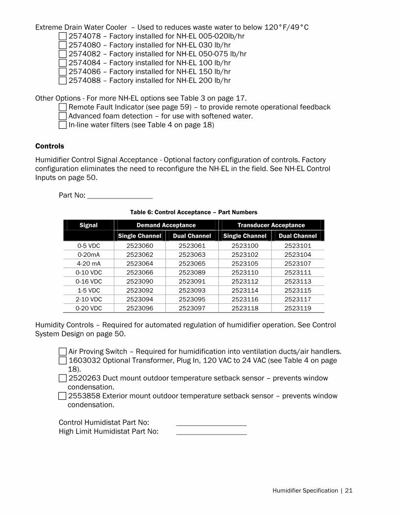
Controls
Humidifier Control Signal Acceptance - Optional factory configuration of controls. Factory
configuration eliminates the need to reconfigure the NH-EL in the field. See NH-EL Control
Inputs on page 50.
Part No:
Table 6: Control Acceptance – Part Numbers
Signal Demand Acceptance Transducer Acceptance
Single Channel Dual Channel Single Channel Dual Channel
0-5 VDC 2523060 2523061 2523100 2523101
0-20mA 2523062 2523063 2523102 2523104
4-20 mA 2523064 2523065 2523105 2523107
0-10 VDC 2523066 2523089 2523110 2523111
0-16 VDC 2523090 2523091 2523112 2523113
1-5 VDC 2523092 2523093 2523114 2523115
2-10 VDC 2523094 2523095 2523116 2523117
0-20 VDC 2523096 2523097 2523118 2523119
Humidity Controls – Required for automated regulation of humidifier operation. See Control
System Design on page 50.
Air Proving Switch – Required for humidification into ventilation ducts/air handlers.
1603032 Optional Transformer, Plug In, 120 VAC to 24 VAC (see Table 4 on page
18).
2520263 Duct mount outdoor temperature setback sensor – prevents window
condensation.
2553858 Exterior mount outdoor temperature setback sensor – prevents window
condensation.
Control Humidistat Part No:
High Limit Humidistat Part No:

22 | Humidifier Specification
Table 7: Nortec Humidistats
Part Num.
Demand Transducer
Digital Mech. 0-10
VDC
2-10
VDC On/Off
Fan
Start Duct
Mount
Wall
Mount
Duct
Mount
Wall
Mount
2548732
2548731
2520273*
1510142
2520266*
1329102
1329108
1509858
1509857
*Remotely mounted digital controller included to provide ease of access.
Digital Communication Protocol – For interface with building automation systems(see Digital
Control on page 55 or Nortec document 2574199 BACnet/Lonworks Supplemental manual).
BACnet IP/MSTP (Standard)
Modbus (Standard)
Nortec Online (Standard)
2574194 BACnet Tested Laboratories certified BACnet IP – For BTL certified networks
2574193 BACnet Tested Laboratories certified BACnet MS/TP – For BTL certified
networks
2574194 Lonworks
Steam Distribution
Select a distributor that exceeds the production capacity of the humidifier(s), fits the duct/air
handler size (if applicable), and accommodates the steam outlet connections to the humidifier.
Options - See Steam Distribution Systems on page 45.
1710010 –140°F/60°C Self-Actuated Condensate Cooler.
1710020 – 140°F/60°C 24V Electric Condensate Cooler.
2572615 – Remote blower pack 005-100lb/hr, 110-120V, 1 Phase.
(see Blower Packs on page 46)
SAM-e (See 1503529 SAM-e Engineering manual for selection information)
Steam Inlet Adapter:
SAM-e Header:
Steam Tubes: Quantity:
Insulation (Improves energy efficiency by as much as 70%)
Mounting Frame (required for vertical duct installation)
Steam Distributor (See 1506117 Steam Distributor Installation manual)
Part Number: Quantity:

Humidifier Specification | 23
Steam Hose (See Atmospheric Steam Distribution Lines on page 47.)
1328810 Hose 7/8 in. ID. Steam Tube Length:
1328820 Hose 1 3/4 in. ID. Steam Tube Length:
1328834 Hose 3/8 in. ID. Condensate Tube Length:
Steam Line Reducers (For adapting the steam line diameter to various fittings)
1507846 –1¾ to 7/8 in. Copper Quantity:
1508165 - 1¾"o 7/8 in. Stainless Steel Quantity:
Steam Line Tee (For steam line condensate drainage)
1329634 – Small Tee adapter 7/8 x 7/8 x 3/8 Quantity:
1329635 – Large Tee adapter 1 3/4 x 1 3/4 x 3/8 Quantity:

24 | Humidifier Specification
Dimensions
Figure 8: NH-EL 005-030 Physical Data & Dimensions

Humidifier Specifications | 25
Figure 9: NH-EL 050-100 Physical Data & Dimensions

26 | Humidifier Specification
Figure 10: NH-EL 150-200 Physical Data & Dimensions

Humidifier Specifications | 27
Figure 11: NH-EL Space 005-030 Physical Data & Dimensions
Empty Weight 83lbs (38kg)
Full Weight
005-010 93 lbs (42kg)
020 103lbs (47kg)
030 118lbs (54kg)
Water Inlet Pressure 30-80 PSI (2.07 – 5.52 BAR)
Blower Pack Speed Setting
LOW HIGH
Clearance Front 132in.
(355.3cm)
120in.
(305cm)
Clearance Left and Right 12in.
(30.5cm)
12in.
(30.5cm)
Clearance Floor 12in.
(30.5cm)
12in.
(30.5cm)
Clearance Ceiling 24in.
(61cm)
24in.
(61cm)
Clearances based upon 72°F (22.2°C), 43% RH with
blower on High speed setting. See Location on page 41.

28 | Humidifier Specification
Figure 12: NH-EL Space 050-100 Physical Data & Dimensions
Empty Weight 123lbs (56kg)
Full Weight 188 lbs (85kg)
Water Inlet Pressure 30-80 PSI
(2.07 – 5.52 BAR)
Blower Pack Speed Setting
LOW HIGH
Clearance Front Not
recommended
248in.
(630cm)
Clearance Left and Right Not
recommended
30in.
(76cm)
Clearance Floor Not
recommended
24in.
(61cm)
Clearance Ceiling Not
recommended
36in.
(91cm)
Clearances based upon 72°F (22.2°C), 43% RH with
blower on High speed setting. See Location on page 41.

Humidifier Specifications | 29
Model Specifications
Table 8: NH-EL Specifications
Phase Capacity
lb (kg) Voltage
NH-EL
Part No. Amps
Max Ext
Fuse KW
Standard
Cylinder
Fill
gal (l)
per min
Net/Full
Weight
lb (kg)
1
5 (2.3) 110-120 2573379 15.9 20 1.9 202 0.13 (0.5)
45/55
(21/25) 10 (4.5)
208 2573380 18.3 25 3.8 202
0.13
(0.5)
220-240 2573382 15.9 20 3.8 202
277 2573383 13.7 20 3.8 202
380* 2573384 9.8 15 3.8 203
440-480 2573385 7.9 15 3.8 204
550-600 2573386 6.3 15 3.8 204
20 (9)
208 2573388 36.6 45 7.6 321
0.13
(0.5)
45/65
(21/30)
220-240 2573389 31.7 40 7.6 321
277 2573390 27.5 35 7.6 321
380* 2573391 19.7 25 7.6 305
440-480 2573392 15.9 20 7.6 309
550-600 2573393 12.7 20 7.6 309
3
20 (9)
208 2573394 21.1 30 7.6 303
0.13
(0.5)
220-240 2573395 18.3 25 7.6 303
380* 2573396 11.4 15 7.6 311
440-480 2573397 9.2 15 7.6 311
550-600 2573398 7.3 15 7.6 311
30
(13.5)
208 2573399 31.7 40 11.4 421
0.3
(1.2)
45/80
(21/37)
220-240 2573400 27.5 35 11. 4 421
380* 2573401 17.1 25 11.4 407
440-480 2573402 13.7 20 11.4 411
550-600 2573403 11.0 15 11.4 411
50
(22.5)
208 2573404 51.9 70 18.7 621
0.5
(2.0)
85/150
(39/68)
220-240 2573405 45.0 60 18.7 621
380* 2573406 28.4 40 18.7 603
440-480 2573407 22.4 30 18.7 605
550-600 2573408 18.0 25 18.7 605
75 (34)
208 2573409 77.9 100 28.1 621
0.5
(2.0)
220-240 2573410 67.4 90 28.1 621
380* 2573411 42.6 60 28.1 603
440-480 2573412 33.8 45 28.1 605
550-600 2573413 27.0 35 28.1 605
100 (45)
208 2573414 94.4 125 34.0 621
0.9
(3.3)
220-240 2573415 90.0 125 37.4 621
380* 2573416 56.8 80 37.4 603
440-480 2573417 45.0 60 37.4 605
550-600 2573418 36.0 45 37.4 605
* 50 Hertz, not UL listed ** Per cylinder basis.

30 | Humidifier Specification
Table 8: NH-EL Specifications Continued
Phase Capacity
lb (kg) Voltage
NH-EL
Part No. Amps
Max Ext
Fuse KW
Standard
Cylinder
Fill
gal (l)
per min
Net/Full Weight
lb (kg)
3
150 (68)
208 2573419 155.8 200 56.1 621
0.5**
(2.0**)
120/245
(55/112)
220-240 2573420 135.0 175 56.1 621
380* 2573421 85.2 110 56.1 603
440-480 2573422 67.4 90 56.1 605
550-600 2573423 54.0 70 56.1 605
200 (90)
208 2573424 188.7 250 68.0 621
0.9**
(3.3**)
220-240 2573425 180.0 225 74.8 621
380* 2573426 113.7 150 74.8 603
440-480 2573427 90.0 125 74.8 605
550-600 2573428 72.0 90 74.8 605
* 50 Hertz, not UL listed ** Per cylinder basis.
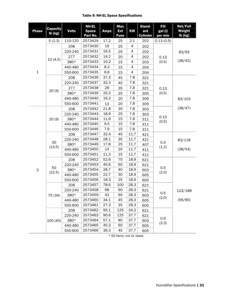
Humidifier Specifications | 31
Table 9: NH-EL Space Specifications
Phase Capacity
lb (kg) Volts
NH-EL
Space
Part No.
Amps
Max
Ext
Fuse
KW
Stand-
ard
Cylinder
Fill
gal (l)
per min
Net/Full
Weight
lb (kg)
1
5 (2.3) 110-120 2573429 17.2 25 2.1 202 0.13 (0.5)
83/93
(38/42) 10 (4.5)
208 2573430 19 25 4 202
0.13
(0.5)
220-240 2573431 16.5 25 4 202
277 2573432 14.2 20 4 202
380* 2573433 10.2 15 4 203
440-480 2573434 8.2 15 4 204
550-600 2573435 6.6 15 4 204
20 (9)
208 2573436 37.3 45 7.8 321
0.13
(0.5)
83/103
(38/47)
220-240 2573437 32.3 40 7.8 321
277 2573438 28 35 7.8 321
380* 2573439 20.3 25 7.8 305
440-480 2573440 16.2 20 7.8 309
550-600 2573441 13 20 7.8 309
3
20 (9)
208 2573442 21.8 30 7.8 303
0.13
(0.5)
220-240 2573443 18.9 25 7.8 303
380* 2573444 11.9 15 7.8 311
440-480 2573445 9.5 15 7.8 311
550-600 2573446 7.6 15 7.8 311
30
(13.5)
208 2573447 32.4 40 11.7 421
0.3
(1.2)
83/118
(38/54)
220-240 2573448 28.1 35 11.7 421
380* 2573449 17.8 25 11.7 407
440-480 2573450 14 20 11.7 411
550-600 2573451 11.3 15 11.7 411
50
(22.5)
208 2573452 52.6 70 18.9 621
0.5
(2.0)
123/188
(56/85)
220-240 2573453 45.6 60 18.9 621
380* 2573454 28.7 40 18.9 603
440-480 2573455 22.7 30 18.9 605
550-600 2573456 18.3 25 18.9 605
75 (34)
208 2573457 78.6 100 28.3 621
0.5
(2.0)
220-240 2573458 68 90 28.3 621
380* 2573459 43 60 28.3 603
440-480 2573460 34.1 45 28.3 605
550-600 2573461 27.3 35 28.3 605
100 (45)
208 2573462 95.1 125 34.2 621
0.9
(3.3)
220-240 2573463 90.6 125 37.7 621
380* 2573464 57.1 80 37.7 603
440-480 2573465 45.3 60 37.7 605
550-600 2573466 36.3 45 37.7 605
* 50 Hertz, not UL listed

32 | Humidifier Specification
Sample Specification
PART 1 - GENERAL
1.1 Work Included:
a. Nortec NH-EL Series electrode steam humidifier[s] as indicated on drawing[s] and as
indicated on schedule[s].
b. Complete and operable humidification system [which meets applicable building codes]
c. Equipment start-up and project inspection by qualified factory trained representative.
1.2 Quality Assurance:
a. Certifications, C-UL US Listed.
b. ISO 9001-2008.
c. ANSI/NFPA 70 - National Electrical Code.
d. ARI 640, "Standard for Commercial and Industrial Humidifiers.
e. ASHRAE SSPC 135 BACnet
1.3 Related Sections:
a. 23 Mechanical General
b. 23[ ] Piping Installation
c. 23[ ] Control System
1.4 Submittals:
a. Submit product data under provisions of Section 23. Include product description, model,
dimensions, component sizes, rough-in requirements, service sizes, and finishes. Include
rated capacities, operating weights, furnished specialties, and accessories.
b. Submit manufacturer's installation instructions.
c. Submit operation and maintenance data.
d. Submit coordination drawings. Detail fabrication and installation of humidifiers. Include
piping details, plans, elevations, sections, details of components, and dispersion tubes.
Detail humidifiers and adjacent equipment. Show support locations, type of support,
weight on each support, and required clearances.
e. Submit wiring diagrams including power, signal, and control wiring. Differentiate between
manufacturer-installed and field-installed wiring.
f. Submit minimum water quality requirements and water pressure requirements.
1.5 Schedules:
a. Refer to information contained in schedule[s] attached to this specification.
b. Humidifiers to be of type, capacity, and arrangement as listed in schedule[s].
c. Include accessories listed in schedule[s] and those accessories required for type of unit.
ELECTRODE STEAM HUMIDIFICATION SYSTEM - NORTEC MODEL NH-EL
PART 2 - PRODUCTS
2.1 Provide Nortec NH-EL electrode humidifier generating mineral-free, sterile steam from a
potable water supply Packaged unit, wall mounted, atmospheric steam generation using an
electrode steam cylinder[s]. Resistive element technology and boiler steam (pressure
steam) technology not acceptable.

Humidifier Specifications | 33
2.2 Unit[s] to be complete with:
a. Touchscreen controller with standard building automation and Online connectivity:
i. Intuitive touchscreen control with color graphic user interface.
ii. Standard building automation communication protocols BACnet IP, BACnet MSTP
and Modbus. Additional hardware required for building automation
communication not acceptable.
iii. Standard Nortec Online connectivity for remote monitoring and factory diagnostic.
iv. Embedded web interface for easy configuration and remote monitoring from any
computer with a web browser over a local area network (LAN) connection.
v. USB interface for new software/feature upload and download of operational
information.
vi. Single or dual channel analog signal acceptance, supporting both demand and
transducer control. Ability to control set point from humidifier control when using
transducer controls.
b. Standard remote monitoring with Nortec Online
i. Integrated hardware and software allows for remote end-user and factory
diagnostic of humidifier(s) via the internet.
ii. Humidifier parameter data and performance trending data can be exported
remotely using the internet.
iii. Humidifier will be accessed via the internet by registering humidifier to
www.norteconline.com. Controls contractor to provide internet access to
humidifier through Ethernet cable with RJ-45 connection.
c. Packaged system with Nortec electrode cylinder technology:
i. Nortec cylinder optimized for humidifier capacity and supply voltage. Cylinder
must have welded seam to ensure watertight and have high water sensor to
prevent overfilling.
ii. Durable powder coated steel cabinet with zero side clearance requirement for
minimal footprint (excluding distribution attachments).
iii. Insulating air gap between plumbing and electrical compartment for increased
electronic reliability.
iv. Standard internal drain water tempering to ensure maximum 140°F [60°C] drain
water. External drain water cooler not acceptable.
v. Integral fill cup with minimum 1-inch [25 mm] air gap to prevent back siphoning.
vi. Full cylinder indication and pre-notification of automatic shutdown at end of
cylinder life.
vii. Automatic pulse feature to clean any obstruction from the drain solenoid valve if
required.
viii. Automatic off-season shut-down [after 3 days of "no call"] will completely drain the
cylinder[s] and automatically restart on call for humidity. Adjustable on/off and
time sequence. Provides extended cylinder life, while ensuring stagnant water
does not remain in the system.
ix. Plumbing door interlock safety switch to allow power interruption when installing
or servicing the humidifier.
d. Nortec Auto-Adaptive Control water management:
i. Advanced water management utilizing the patented Proportional plus Integral
Auto-Adaptive Control system for optimal energy efficiency, water usage and
cylinder life.
ii. 98% thermal efficiency from startup until end of cylinder life.
iii. Drains automatically optimized to water conditions to maximize cylinder and
reduce water usage.

34 | Humidifier Specification
iv. Modulating output between 20% and 100% of rated capacity.
2.3 Optional Accessories
a. Refer to 'Option schedule'
PART 3 - EXCECUTION
3.1 Installation:
a. Install humidifiers per manufacturers' instructions.
b. Install with required clearance for service and maintenance.
3.2 Accessories:
a. Install accessories in accordance with manufacturer's recommendations.
3.3 Commissioning:
a. Start-up of humidifier to be by factory trained technician.

Humidification Load | 35
Total Humidification Load The total humidification load is the sum of three primary considerations:
Base Humidification Load - The humidification load required to increase unconditioned supply
air, from the worst case scenario, to meet the design requirements for the conditioned
environment. This is typically the largest contributing factor to the total humidification load. See
page 35.
Moisture Content Equilibrium - Materials stored in a conditioned environments may retain
moisture content out of equilibrium with the moisture content of that environment. Depending
upon the hygroscopic principals of the material it may have an equalizing effect on the
environment, thereby increasing or decreasing the relative humidity. See page 38.
Condensate Losses – Convection heat transfer from steam in the steam distribution system will
revert the steam to a liquid state, detracting from the gross humidifier output. See page 38.
Safety Margin –Once all other considerations have been made, it may be prudent to
increase the capacity of the humidifier if the design conditions are going to regularly
keep the unit operating at or near or maximum operational capacity.
Base Humidification Load Calculating
Total Unconditioned Air Supply Volume
The total volume of incoming unconditioned air per hour, forced and naturally ventilated, must
be determined. The incoming volume depends on the construction of the conditioned
environment and the type of air circulation system used.
Forced Ventilation – Typically, an air handler system will exchange a fixed percentage of
conditioned air for unconditioned air. This unconditioned air is the volume of air that requires
humidification.
Air handler systems vary by design but will rely upon adding or removing volumes of air from a
controlled environment. Air handling systems that add air to the conditioned environment will
have a total forced air volume equivalent to the unconditioned supply air volume. Air handling
systems that exhaust air from the conditioned environment must have at least an equal volume
of unconditioned air reintroduced; That equal volume of unconditioned air will be the total
forced air volume.
Nortec provides a convenient method to calculate the humidification load for any application
with our online program - Humidifier Engineering and Load-sizing Program (H.E.L.P.).
Additionally this program can also assist with absorption distance calculations, selection of
humidifiers, distributors, controls, and accessories. For access to this program please go to:
www.NortecHelp.com
There are tutorials on the use of this program available from the Literature & Media section of
the Nortec website www.Humidity.com. Additional information on the effects of humidity,
calculating relative humidity, load calculations and recommended design conditions can be
found in the Nortec Humidification Load Calculation manual (2553856).

36 | Humidification Load
Accounting for Economizer Cycles - Under normal heating conditions the unconditioned supply
air volume is usually relatively small to avoid large heating and conditioning treatments.
However when the economizer cycle is in operation, the unconditioned air volume may be as
high as 100% of the total ventilation. To calculate the humidification load for a system with an
economizer cycle the air ventilation and thermal load must be calculated for each month in
which the economizer mode may operate to determine the highest humidification load.
Natural Ventilation – A system that does not rely upon direct mechanical means to provide air
ventilation to the conditioned environment. Air will ventilate through openings in the building
envelope. The amount of makeup air is calculated based on the volume of the conditioned
space and an estimate of air changes per hour.
Unconditioned Supply Air Moisture
Once the total volume of unconditioned supply air is known, the moisture content of this air
must be determined. To ensure the humidifier capacity will be able to satisfy design conditions,
we must base our calculations off the lowest unconditioned supply air temperatures and
humidity that can be expected on a yearly basis. In applications where the unconditioned supply
air will be drawn from the local atmosphere, Nortec advises utilizing the weather data compiled
by geographic location published by the ASHRAE Climate Data Centre.
Once the lowest temperature for the given geographic location is known, use Table 10 (IP units)
or Table 11 (SI units) on page 37 to determine the moisture (lb) per cubic foot of air at 100%
humidity. Multiply the 100% moisture content by the lowest humidity levels for the geographic
location.
Max Supply Moisture(lb/cu.ft) = The 100% RH moisture content obtained from the tables on
page 37 for the lowest anticipated supply air temperature for the unconditioned air source.
Low Humidity(%) = The lowest anticipated humidity (percentage of Relative Humidity) for the
unconditioned supply air source.
Conditioned Air Moisture
The moisture content for the designed air conditions must be determined. To ensure the
humidifier capacity will be able to satisfy design conditions, we must base our calculations off
the highest desired design air temperatures and humidity.
Once the highest design temperature and highest humidity have been determined for the
application, use Table 10 (IP units) or Table 11 (SI units) on page 37 to determine the moisture
(lb) per cubic foot of air at 100% humidity. Multiply the 100% moisture content by the highest
required humidity levels for the conditioned environment.
Max Supply Moisture(lb/cu.ft) = The 100% RH moisture content obtained from the tables on
page 37 for the highest design air temperature.
Design Humidity(%) = The highest required humidity (percentage of RH) for the design
conditions.

Humidification Load | 37
Base Humidification Load
The base humidification load equates to the difference between the Conditioned Air
Moisture(lb/cu.ft) and Supply Air Moisture(lb/cu.ft) multiplied by the hourly Unconditioned Air
Supply Volume (CFM).
Base Load Base humidification load as determined by calculating the moisture required to bring
the unconditioned supply air to meet the conditioned air requirements.
Supply Air Unconditioned Air Supply Volume in cubic feet of air per hour as obtained from Total
Unconditioned Air Supply Volume on page 35.
Conditioned Air Moisture Conditioned Air Moisture in pounds per cubic foot as obtained from
page36.
Supply Moisture Unconditioned Supply Air Moisture in pounds per cubic foot as obtained on
page 36.
Table 10: Moisture Content of Air at 100% RH (IP units)
°F lb/cu.ft °F lb/cu.ft °F lb/cu.ft °F lb/cu.ft °F lb/cu.ft
-20 0.0000343 41 0.000424 61 0.000857 81 0.00163 101 0.00293
-10 0.0000414 42 0.000440 62 0.000886 82 0.00168 102 0.00302
-5 0.0000500 43 0.000457 63 0.000916 83 0.00173 103 0.00310
0 0.0000686 44 0.000474 64 0.000946 84 0.00178 104 0.00319
5 0.0000871 45 0.000491 65 0.000979 85 0.00184 105 0.00328
10 0.000111 46 0.000509 66 0.00101 86 0.00190 106 0.00337
15 0.000141 47 0.000527 67 0.00104 87 0.00195 107 0.00347
20 0.000177 48 0.000547 68 0.00108 88 0.00201 108 0.00356
25 0.000223 49 0.000567 69 0.00111 89 0.00207 109 0.00366
30 0.000279 50 0.000587 70 0.00116 90 0.00213 110 0.00376
31 0.000291 51 0.000609 71 0.00119 91 0.00220 111 0.00387
32 0.000304 52 0.000630 72 0.00123 92 0.00226 112 0.00397
33 0.000316 53 0.000651 73 0.00127 93 0.00233 113 0.00408
34 0.000327 54 0.000674 74 0.00131 94 0.00240 114 0.00419
35 0.000340 55 0.000699 75 0.00135 95 0.00247 115 0.00430
36 0.000353 56 0.000723 76 0.00139 96 0.00254 120 0.00491
37 0.000366 57 0.000747 77 0.00144 97 0.00262 125 0.00559
38 0.000380 58 0.000773 78 0.00149 98 0.00269 130 0.00634
39 0.000394 59 0.000800 79 0.00154 99 0.00277 135 0.00719
40 0.000409 60 0.000829 80 0.00158 100 0.00285 140 0.00812

38 | Humidification Load
Table 11: Moisture Content of Air at 100% RH (SI units)
°C kg/cu.m °C kg/cu.m °C kg/cu.m °C kg/cu.m °C kg/cu.m
-30 0.000578 -10 0.00218 10 0.00943 30 0.0303 50 0.0828
-29 0.000553 -9 0.00238 11 0.0100 31 0.0320 51 0.0867
-28 0.000540 -8 0.00259 12 0.0107 32 0.0337 52 0.0908
-27 0.000540 -7 0.00281 13 0.0114 33 0.0356 53 0.0951
-26 0.000551 -6 0.00305 14 0.0121 34 0.0375 54 0.0995
-25 0.000573 -5 0.00330 15 0.0129 35 0.0395 55 0.104
-24 0.000606 -4 0.00357 16 0.0137 36 0.0416 56 0.109
-23 0.000650 -3 0.00385 17 0.0145 37 0.0438 57 0.114
-22 0.000704 -2 0.00415 18 0.0154 38 0.0461 58 0.119
-21 0.000769 -1 0.00447 19 0.0163 39 0.0485 59 0.124
-20 0.000845 0 0.00481 20 0.0173 40 0.0510 60 0.130
-19 0.000931 1 0.00516 21 0.0183 41 0.0536 61 0.136
-18 0.00103 2 0.00554 22 0.0194 42 0.0563 62 0.142
-17 0.00113 3 0.00594 23 0.0206 43 0.0592 63 0.148
-16 0.00125 4 0.00636 24 0.0218 44 0.0621 64 0.154
-15 0.00138 5 0.00680 25 0.0230 45 0.0652 65 0.161
-14 0.00152 6 0.00727 26 0.0243 46 0.0685 66 0.168
-13 0.00167 7 0.00777 27 0.0257 47 0.0718 67 0.175
-12 0.00183 8 0.00829 28 0.0272 48 0.0753 68 0.182
-11 0.00200 9 0.00884 29 0.0287 49 0.0790 69 0.190
Moisture Content Equilibrium
Materials stored in conditioned environments may retain moisture content out of equilibrium
with the moisture content of that environment. Depending upon the hygroscopic principals of
the material it may have an equalizing effect on the environment, thereby increasing
(desorption) or decreasing (absorption) the Relative Humidity (RH) of the surrounding
environment. Any materials stored in the conditioned environment that may emit or absorb
significant moisture from the atmosphere should have the hygroscopic principals of that
material assessed with the manufacturer. Once the severity of this influence is known it should
be incorporated into the total humidification load.
Condensate Loss
Convection heat transfer from steam in the steam distribution system will revert the steam to a
liquid state, detracting from the gross humidifier output. An estimate of the condensate losses
throughout the distribution system should be done to ensure the total humidifier capacity, less
this condensation loss, will still satisfy the total load requirement.
Hygroscopic Regain – is defined as the amount of water a completely dry material will absorb from the air through desorption or adsorption. Any hygroscopic product that is purchased and sold by weight must have a carefully controlled environment.

Humidification Load | 39
Distributor Losses - The distributor system is often the largest contributor to condensate losses
in a properly designed distributor system. These losses can be minimized by installing insulation
kits available for most advanced distributors.
The amount of humidification lost to condensation is dependent upon the design of the
distributor system. Reference the engineering guide of the distributor for specific condensation
loss information. Additional information on calculating condensate loss and the savings of
insulating distributors can be found in Nortec white paper “Nortec Stainless Steel Air Gap
Insulation R Value”.
Supply Line Losses – Condensate losses per linear foot can be roughly estimated in a system
with properly designed atmospheric steam lines. Total length of the atmospheric steam line
must be taken into account, that is the sum of linear length of the tube and equivalent length of
every fitting. For equivalent lengths of common fittings see Table 12. Once total equivalent
linear length is determined, Table 13 can be used to estimate the humidifier capacity lost to
supply line losses. For design information on steam lines see Atmospheric Steam Distribution
Lines on page 47.
Table 12: Approximate Equivalent Length of Atmospheric Steam Line Fittings
Nominal tube
size
Standard
90° elbow
Standard
45° elbow
Side-outlet
tee
Full Bore Gate
valve* Globe valve*
0.75” - 0.875” 2 ft 1 ft 4 ft 0.4 ft 18 ft
1.5” - 1.75” 3.5 ft 1.75 ft 7 ft 0.8 ft 34 ft
3” 5 ft 2.5 ft 11 ft 1.1 ft 54 ft
4” 8 ft 4 ft 15 ft 1.6 ft 80 ft
*Valve in full open position.
Table 13: Approximate Condensate per Foot of Atmospheric Steam Line
Steam
capacity
(lbs/hr)*
MED-L copper tube
nominal steam line
size
Stainless steel
tube (thickness
0.065”)
Steam loss per
foot in
condensation
4-30 0.75” 0.875” 0.06 lbs/ft
30-100 1.5” 1.75” 0.11 lbs/ft
200-300 3” 3” 0.16 lbs/ft
400-660 4” 4” 0.22 lbs/ft
Note: Based on 1” pipe insulation at 3” W.C. duct static pressure.
*Inclusive.
Note: Nortec stainless steel air-gap insulation provides one method for reducing a distributor losses and conserving energy. See Nortec publication 1503529 – SAM-e Engineering Manual for more information on specifying SAM-e insulation.
40 | Humidifier Installation
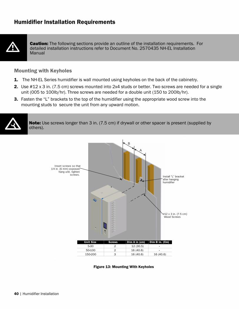
Humidifier Installation Requirements
Mounting with Keyholes
1. The NH-EL Series humidifier is wall mounted using keyholes on the back of the cabinetry.
2. Use #12 x 3 in. (7.5 cm) screws mounted into 2x4 studs or better. Two screws are needed for a single
unit (005 to 100lb/hr). Three screws are needed for a double unit (150 to 200lb/hr).
3. Fasten the “L” brackets to the top of the humidifier using the appropriate wood screw into the
mounting studs to secure the unit from any upward motion.
B
A
Install “L” bracketafter hanging humidifier
#12 x 3 in. (7.5 cm) Wood Screws
Insert screws so that1/4 in. (6 mm) exposed,
hang unit, tighten screws.
Unit Size Screws Dim A in (cm). Dim B in. (Cm)
5-30 2 12 (30.5) -
50-100 2 16 (40.6) -
150-200 3 16 (40.6) 16 (40.6)
SPACESPACE
SPACESPACE
Caution: The following sections provide an outline of the installation requirements. For detailed installation instructions refer to Document No. 2570435 NH-EL Installation Manual
Note: Use screws longer than 3 in. (7.5 cm) if drywall or other spacer is present (supplied by others).
Figure 13: Mounting With Keyholes

Humidifier Installation | 41
Location
Mount on a suitable wall or vertical surface. Do not sit the unit on the floor. Allow clearances required
for plumbing and electrical connections.
Install only in areas with ambient temperature 41-104°F (5–40°C), relative humidity 5 - 95% RH (non-
condensing). Blower packs should not be installed near cold surfaces or where dew point may be
reached.
The humidifier cannot be used as a structural member. All piping connected to the unit must be
supported independently.
Ensure mounting surface can support the full weight of the humidifier and accessories. Specific
humidifier weights are detailed in Table 8 on page 29 and Table 9 on page 29.
Install in a location that facilitates regular maintenance and where; electrical, water, drain (with proper
slope), connections can be made to the humidifier.
When possible, install below the steam distributor. Take care to provide proper steam line routing and
proper condensate traps as per the Steam Distribution section on page 22.
DO NOT locate the humidifier any further then absolutely necessary from the steam distributor. Net
output will be reduced as a result of efficiency loss of steam lines.
Clearance dimensions shown are for reference only and are the minimum required for maintenance of
the humidifier. Consult local and national codes before final location and installation. Nortec does not
accept responsibility for installation code violations.
*Side clearance not required, only recommended for ease of service access.
Figure 14: Installation Location/Clearance
6 in. (15 cm)
RecommendedSide
Clearance
36 in. (91.5 cm)
Min. Front Clearance
24 in.(61 cm)Min Height
Mount HumidifierLevel
5-95%
(See Table for
Blowerpack clearances)
(See Table for Blowerpack clearances)
(See Table for Blowerpackclearances)
If Blowerpack is used,mount so that the steam
outlet is at least 96 in. (244 cm)
above ground level.

42 | Humidifier Installation
Table 14: Minimum Clearances for Blower Packs
Supply steam
lbs(kg) per hour
Speed
setting
Frontal
Clearance
Inch (cm)
Overhead
Clearance
Inch (cm)
Left side
Clearance
Inch (cm)
Right side
Clearance
Inch (cm)
5-30 (2.3-13.6) Low 132 (336) 12(31) 12 (31) 12 (31)
5-30 (2.3-13.6) High 120 (305) 12(31) 12 (31) 12 (31)
50-100 (22.7-45.4) High* 248 (630) 36 (91) 30 (76) 30 (76)
Based upon Nominal Conditions 72˚F (22.2˚C), 43% RH.
*Low speed not advised for 100lb/hr.

Humidifier Installation | 43
Min. 7/8 in. OD drain line. Keep as short as possible.
Slope down to floor drain or main drain.Increase size if combiningmultiple drains as in double unit.
1.2 in. (30 mm). OD
un-threaded outlet with factory supplied bent hose and clamp.
Air gap required. 2 1/2 in. to 7/8 in. copper reducer is ideal. (NORTEC option P/N 2522172)
Hose must not touch the bottom of the funnel.
Always install a watershut-off valve.
1/2 in. NPTUse union to connect
supply pipe to unit.
*Pipe and water shut-off valve not supplied by NORTEC.
Plumbing
Figure 15: NH-EL Water Supply and Drain Connection
Table 15: NH-EL Supply Water Requirements
Conductivity
(µSiemens)
Hardness Range
(GPG)
Silica Range
(ppm)
Alkalinity Range
(pH)
150-1250* 0-10 0-4
7-7.5 0-3 0-14
*Default humidifier configuration supports approximately 330-670µS

44 | Humidifier Installation
All water supply and drain line connections should be installed in accordance with local
plumbing codes.
Supply cold potable water, not purified water such as reverse osmosis or demineralized. See
Table 8 and Table 9 for supply water flow rates.
Use material suitable for 212°F (100°C) for drain and condensate lines.
The drain line should not end in a sink used frequently by personnel, or where plumbing
codes prohibit. Route to a floor drain or equivalent for safety reasons.
Ensure drain line is adequately sized to provide free and easy draining, an air gap must be
installed as shown. A restricted drain can cause cylinder water to over concentrate and
result in poor operation or result in water backing up at the air gap.
Electrical
Caution: Wiring to be performed by a licensed electrician.
L1L2
Ground
L1L2
Ground .
L1L2L3
Neutral
Ground
L1L2L3
Neutral
Ground
L1L2
Ground
L1Neutral
Ground
L1L2L3
Neutral
Ground
L1
L2L3
Ground
Three Phase NH-EL
Single Phase NH-EL
Single Phase Supply
Three Phase Supply(Note: Load will be unbalanced)
Three Phase Supply
DedicatedCircuit Breaker
or Fused Disconect
Note:1
2
3
4
5
Install a disconnect within view of the humidifier.
Optional internal fuses are not a substitute for external fuses.
Dedicated external fused disconnect must be installed. Fusing must not exceed max circuit protection as indicated on the specification label.
Ensure that adequate power is available to carry full humidifier amp draw as indicated on the specification label.
All wiring to be in accordance with national and local electrical codes.
EXT
INT
EXT
INT
E
XT
I
NT
EXT
INT
.
Three Phase Supply(Note: Load will be unbalanced)
Figure 16: NH-EL Primary Power Connections
Humidifier Installation | 45
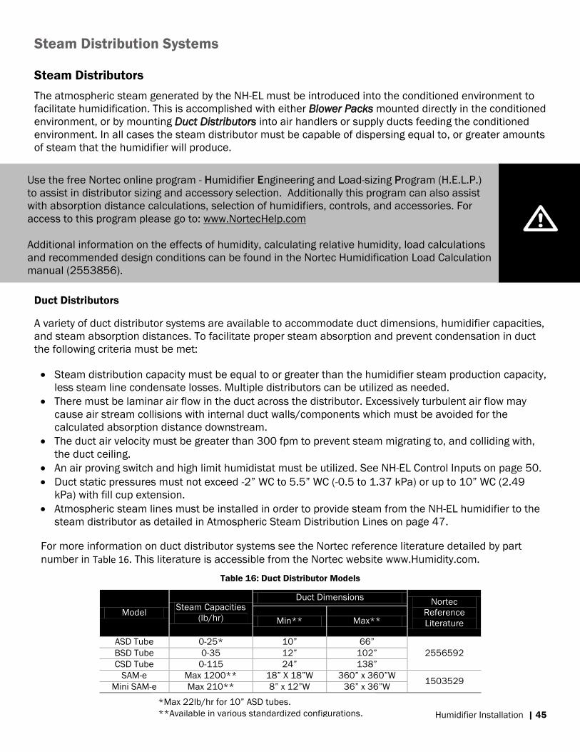
Steam Distribution Systems
Steam Distributors
The atmospheric steam generated by the NH-EL must be introduced into the conditioned environment to
facilitate humidification. This is accomplished with either Blower Packs mounted directly in the conditioned
environment, or by mounting Duct Distributors into air handlers or supply ducts feeding the conditioned
environment. In all cases the steam distributor must be capable of dispersing equal to, or greater amounts
of steam that the humidifier will produce.
Duct Distributors
A variety of duct distributor systems are available to accommodate duct dimensions, humidifier capacities,
and steam absorption distances. To facilitate proper steam absorption and prevent condensation in duct
the following criteria must be met:
Steam distribution capacity must be equal to or greater than the humidifier steam production capacity,
less steam line condensate losses. Multiple distributors can be utilized as needed.
There must be laminar air flow in the duct across the distributor. Excessively turbulent air flow may
cause air stream collisions with internal duct walls/components which must be avoided for the
calculated absorption distance downstream.
The duct air velocity must be greater than 300 fpm to prevent steam migrating to, and colliding with,
the duct ceiling.
An air proving switch and high limit humidistat must be utilized. See NH-EL Control Inputs on page 50.
Duct static pressures must not exceed -2” WC to 5.5” WC (-0.5 to 1.37 kPa) or up to 10” WC (2.49
kPa) with fill cup extension.
Atmospheric steam lines must be installed in order to provide steam from the NH-EL humidifier to the
steam distributor as detailed in Atmospheric Steam Distribution Lines on page 47.
For more information on duct distributor systems see the Nortec reference literature detailed by part
number in Table 16. This literature is accessible from the Nortec website www.Humidity.com.
Table 16: Duct Distributor Models
Model Steam Capacities
(lb/hr)
Duct Dimensions Nortec
Reference
Literature Min** Max**
ASD Tube 0-25* 10” 66”
2556592 BSD Tube 0-35 12” 102”
CSD Tube 0-115 24” 138”
SAM-e Max 1200** 18” X 18”W 360” x 360”W 1503529
Mini SAM-e Max 210** 8” x 12”W 36” x 36”W
Use the free Nortec online program - Humidifier Engineering and Load-sizing Program (H.E.L.P.)
to assist in distributor sizing and accessory selection. Additionally this program can also assist
with absorption distance calculations, selection of humidifiers, controls, and accessories. For
access to this program please go to: www.NortecHelp.com
Additional information on the effects of humidity, calculating relative humidity, load calculations
and recommended design conditions can be found in the Nortec Humidification Load Calculation
manual (2553856).
*Max 22lb/hr for 10” ASD tubes.
**Available in various standardized configurations.

46 | Humidifier Installation
Blower Packs
Nortec Blower Packs create an air stream to facilitate absorption of the atmospheric steam in the
conditioned environment. Once the steam is absorbed the humidity will disperse evenly throughout most
conditioned environments without the need of further mechanical assistance with exception to;
mechanical obstructions, localized variances in temperature, infiltrating air, or materials that have
equalizing moisture effects on the surrounding atmosphere. See Space Distribution Control Design on
page 57.
Blower Packs are available in two configurations: Remotely Mounted (RM-BP) or Built-On (Space). Each has
two speed settings, High speed provides shorter absorption distances, low speed offers quitter operation
with longer absorption distance. The NH-EL Space model comes preassembled with the Blower Pack with
steam line, condensate drainage, and wiring. This increases the standard installation tolerances of the
humidifier as detailed on page 40.
Each Remote Mounted Blower Pack (RM-BP) is capable of supporting 5-100lb/hr. These distribution
methods will require; 120VAC 15 amp power supply, atmospheric steam lines, condensate drainage (See
Atmospheric Steam Distribution Line on page 47). For more information on Blower Packs see Nortec
document 2572641.
*Not to scale Figure 18: Remote Mounted Blower Pack
Figure 17: Blower Pack Configurations

Humidifier Installation | 47
Atmospheric Steam Distribution Lines
Atmospheric steam generated by the NH-EL must be introduced from the humidifier to the steam
distribution system to facilitate humidification of the conditioned environment. If the atmospheric
distribution system creates steam pressures outside -2” WC to 5.5” WC (-0.5 to 1.37 kPa), or up to 10” WC
(2.49 kPa) with fill cup extension when combined with duct static pressures, operation of the humidifier
will be impaired. To prevent this, ensure duct static pressures are within range and all steam line designs
utilize the correct; steam line material, diameter, length, slope, insulation, and condensate drainage. For
more steam line design information see the “Steam Lines and Condensate Returns” section of the
2570435 NH-EL Installation Manual.
Material
Only use Notec steam hose, MED-L copper tube, or stainless steel tube that meets the ID requirements
based on humidifier capacity as detailed in Table 17 on page 48. Consult with the manufacturers of the
steam line materials for information on applications with atmospheric steam.
Length
Maximum recommended steam line lengths are detailed in Table 17 on page 48. Minimize the length of
steam lines to reduce efficiency losses to condensate. Table 12 on page 39 provides equivalent length of
some common fittings that can be used when determining the total equivalent length of steam lines. See
Condensate Loss starting on page 38 for information on calculating efficiency losses based on total
equivalent steam line length.
Condensate
Condensate is formed in the steam line and steam distributor systems. Steam lines must be designed to
minimize the condensate created, and to remove any condensate that will otherwise obstruct the free
venting of the atmospheric steam.
Insulation – a minimum 1 in. pipe insulation is recommended to reduce the condensate created as per
Figure 19.
Minimum Slope – Slope the steam line towards condensate drainage traps as per Figure 20. The minimum
slope with the flow of steam is 2°, against the flow of steam the minimum slope is 10°.
Condensate Traps – The distribution line must be drained at all low points and every 15 ft (4.5m) of linear
steam line. Drainage from the steam line is accomplished with full size Tee fittings as per Figure 20.
MAIN RULES FOR ATMOSPHERIC STEAM LINES
Steam lines must not have any restrictions which could cause back pressure or more than 5.5 in.
W.C. when combined with duct static pressure.
Follow recommended materials, size and length (see Figure 17 on page 46).
Only use Nortec steam hose for short steam runs, (<10 ft./3 m) and adapting to the cylinder
steam outlet.
Slope the steam lines and insulate with 1.0 in. (2.5 cm) pipe insulation minimum as indicated in
Figure 19.
Trap condensate using full size ‘T’ for Traps (see Figure 20).
Operate units/tanks in parallel when installing multiple units or double unit to single steam
distributor (See Double Unit (150-200 lb/hr) on page 14).
Flush steam lines and supply water lines after construction.

48 | Humidifier Installation
Figure 19: Steam Line Slope and Insulation
Condensate Returns
Route condensate back to humidifier fill cup where possible. Clean condensate can be returned to cylinder from the fill cup.
Condensate should not be routed to a sink used frequently by personnel. Route to a floor drain or equivalent. Condensate normally cools in traps but is still hot. A SAM-e or larger steam line generates more condensate and water may not cool in the trap. A drain water cooler option may be installed if required by code.
Large volumes of condensate from multiple humidifiers or SAM-e systems should never be returned to a single humidifier.
Multiple condensate drain points must be trapped individually prior to coupling
Steam DirectionSteam Direction
Steam Direction2 in.(5 cm)
1 ft (30 cm)
1ft (30 cm)0.5 in.(12 mm)
10 Degrees
2 Degrees
Use Appropriate Slope Insulate Pipe
1 in. (2.5 cm) pipe insulation
Minimal Slope (up)
Minimal Slope (down)
12 in. (30 cm) min drop to
top of ‘P’ Trap
P Trap min 6 in. (15 cm)
or duct static
pressure + 2 inwhichever is
greater
Tee is same size as steam line
Use a full size tee, not a 90degree elbow for verticalto horizontal transitions.
‘P’ Traps Use:- NORTEC 0.375 in condensate hose- 1/4 in Med-L copper tubing, or
- 0.375 in stainless steel tubing
Condensate drains must be sloped down.
1 ft (30 cm)0.25 in(0.6 cm)
Minimum Slope.
Figure 20: Condensate Traps

Humidifier Installation | 49
Table 17: Recommended Steam Line Material*, Maximum Length, Losses
NH-EL Maximum Steam MED-L Stainless Possible Steam Losses
Model Line Length Copper Steel (based on 1” insulated copper pipe)
ft (m) Tube Tube lb/hr/ft (kg/hr/m)
5 7 (2)
0.75 0.875 X 0.049W 0.06 (0.09) 10 12 (3.5)
20 17 (5)
30 22 (6.5)
50 43 (13)
1.5 1.75 X 0.065W 0.11 (0.16) 75/150** 47 (14)
100/200** 50 (15)
Oversized Steam Line (Use for longer steam runs)***
5 14 (4)
1 1.125 X 0.049W 0.06 (0.09) 10 24 (7)
20 34 (10)
30 44 (13)
50 86 (26)
2 2.0 X 0.065W 0.11 (0.16) 75/150** 94 (28)
100/200** 100 (30)
Nortec Steam Hose
5-30 5 (1.5) Pt No 1328810 (7/8”) 0.1 (0.15)
50-200** 5 (1.5) Pt No. 1328820 (1 3/4”) 0.15 (0.22) Note: * The use of steam line other than copper, stainless steel tube or Nortec supplied steam line will void the warranty and may adversely affect
the operation of the humidifier
** Use one steam line per cylinder for NH-EL150-200 humidifiers. Do not combine lines except at distributor using a Nortec adapter designed
for that purpose and only if humidifiers are operated in parallel.
*** These diameters require a reducer at humidifier and steam distributor connection
Combining Steam Lines
To combine multiple steam lines from a double unit or from multiple units, always use a Nortec supplied
adapters at the steam distributor. Do not use common steam lines for double units or from multiple
humidifiers. Always operate units or double tank units in parallel. See Double Unit (150-200 lb/hr) on
page 14.
Combine multiplesteam lines at steam
distributor using a
Nortec Adapter
Units must be controlled in parallel.Also applies for double tank models 150/200.
Figure 21: Combining Multiple Steam Lines

50 | Humidifier Installation
Control System Design
The NH-EL is designed to be regulated by an automated control system interfaced to the humidifier’s
control terminal strip, but operation may also be regulated with a computer or building management
system with a compatible digital communication protocol. See Digital Control on page 55 for more
information. Regardless the interface, control components for the conditioned environment will vary
primarily depending upon Duct or Space distribution method. All modulating input signals to the humidifier
must be of a matching type, either transducers (RH Sensor), or humidistats (demand signals). For wiring
use a minimum of 18 AWG and keep as short as possible.
NH-EL Control Inputs
The NH-EL operation can be regulated with Analog Controls supporting up to two modulating inputs and
multiple on/off devices for each cylinder, or with Digital Control using computer or building management
system interface using standard digital communication protocols. For control system designs for the
conditioned environment see Control System Design on page 50.
Multi-Mode
The Multi-Mode function allows connection of up to 16 humidifiers to one control signal (Analog or Digital)
to a designated Master unit. Humidifiers can be configured to operate in parallel or to come on in stages
to match demand. Staged configuration of the units will allow for a lower turn down ratio by using the
smallest capacity humidifier as the master. Parallel configuration allows for connections to common
distributor systems and offers more even wear on all units. For more information see Double Unit (150-
200 lb/hr) on page 14.
Connect up to 16 units (equivalent of 1600 lb/hr) using 18-24 AWG multi-strand, twisted pair,
shielded cable.
Connect humidistats/transducers and security loop to master unit only.
Jump the security loops on slave units.
When connecting double units connect only to driver board A.
Note: Regardless of selecting Analog or Digital controls, Nortec humidifiers must have a closed circuit across the on/off security loop(s) to operate. Nortec highly recommends the use of a High Limit humidistat and an Air Proving switch for duct installations.
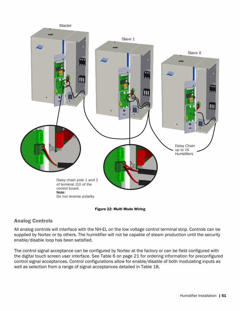
Humidifier Installation | 51
Daisy chain pole 1 and 2
of terminal J10 of the control board.
Do not reverse polarity. Note:
Slave X
Daisy Chain up to 16 Humidifiers
Master
Slave 1
Figure 22: Multi Mode Wiring
Analog Controls
All analog controls will interface with the NH-EL on the low voltage control terminal strip. Controls can be
supplied by Nortec or by others. The humidifier will not be capable of steam production until the security
enable/disable loop has been satisfied.
The control signal acceptance can be configured by Nortec at the factory or can be field configured with
the digital touch screen user interface. See Table 6 on page 21 for ordering information for preconfigured
control signal acceptances. Control configurations allow for enable/disable of both modulating inputs as
well as selection from a range of signal acceptances detailed in Table 18.

52 | Humidifier Installation
Table 18: NH-EL Viable Control Signals
Control Type Control Signal NH-EL
Modulating
Control/High-Limit
Signals
Demand or Transducer 0-5 V, 0-10 V, 1-5 V, 2-10 V,
0-20 V, 0-16 V, 3.2-16 V,
0-20mA, 4-20mA
On/Off
Control/High-Limit
Signals
On/Off Dry Contact
24 VAC or 10 VDC
Security Loop Dry Contact
24 VAC
Double Units - Double humidifiers have two terminal strips and differentiate the controls for each cylinder
with A/B designations as per Figure 7: NH-EL Models on page 13. If controlling double units in Series or
Parallel configuration, only one set of controls will be required to terminal strip A. If controlling with
Independent mode, one set of controls will be required for each terminal strip and each cylinder will
operate independent of the other.
Modulating Control
The NH-EL can be operated with one or two modulating inputs per cylinder. If using two modulating inputs
both signals must be of the same type: Demand signals as provided by an external controller, or
Transducer (RH sensor) signals as provided by an external humidity sensor. In both cases, the humidifier
will not start to produce steam until the calculated system demand exceeds 26%.
Demand Signals When the humidifier receives a demand signal it will calculate the desired steam
production as a percentage of total humidifier capacity proportional to the incoming demand signal as a
percentage of the signal range. When two demand signal inputs are used, the humidifier will respond to
the lowest of the two demand signals.
Transducer Signals When using modulating transducers (RH Sensor), the humidifier will use an internal PI
controller to calculate system demand for each channel input. The calculated system demand for each
input channel will vary depending upon the configurable humidity set points, as well as proportional and
integral functions of the internal controller. If using two transducer signals, two demand signals will be
calculated and the humidifier will respond to the lowest of the two calculated demand signals. Transducers
with a possible zero input are not recommended. The humidifier also supports an optional low and high
humidity alarm warning with reconfigurable humidity triggers.
Safety Control
The NH-EL can be enabled for operation by closing the 24VAC safety loop (pin 1 to pin 2) on the low
voltage control terminal strip. This loop also facilitates on/off control of the humidifier. This security loop
can be used for safety feedbacks that indicate the functional status of the humidification system
components critical to the correct and safe operation of the humidifier.
Humidifier Installation | 53
Digital Control
The digital interface can be configured to control the humidifiers output or can be used to monitor
operation, and change system configurations. Digital communication can be used in conjunction with
Analog controls to regulate the humidifiers operation. With NH-EL humidifiers utilizing the digital
communication features, it is recommended to use transducers for the control and high limit signals.
The NH-EL supports standard communication protocols BACnet IP, MS/TP and Modbus RTU. The desired
integrated communication protocol can be selected and configured using the digital touch screen
interface. With optional hardware kits the humidifier can be adapted to communicate with Lonworks, or
BTL certified BACnet IP/MSTP. See page Table 3: NH-EL Options on page 17 for optional communication
packages and Nortec document 2574199 BACnet/Lonworks Supplemental manual.
BACnet
The NH-EL uses a standard RJ-45 connector and Category (CAT) 5,5E ,or 6 provided by others to connect
to the Integrated Controller board to facilitate BACnet Internet Protocol (IP) and Master Slave Token
Passing (MS/TP) communications. Refer to the Building Management System (BMS) supplier for maximum
recommended communication line lengths. See Nortec document 2574199 – BACnet, LonWorks
supplemental Installation and Operation Manual for control points and connection information.
Modbus RTU
The NH-EL uses a three pole terminal to the Integrated Controller board to facilitate the Modbus EIA-485,
2-wire communications. Connections can be made directly to the provided terminal with the recommended
18-24 AWG Shielded, twisted pair with 120 Ω impedance. Cables of superior quality are also considered
acceptable. To minimize signal loss, a wire run should not exceed 2200 feet (670m). To ensure
communication reliability, it is recommended that no more than 8 nodes are connected to a single
chain/bus. See Nortec document 2560599 – Using Modbus with Nortec Humidifiers for a listing of
Modbus parameters and connection/configuration information available with the NH-EL.
Lonworks and BTL Certified BACnet IP/MSTP
LonWorks and BTL certified BACnet systems require additional optional hardware. See Nortec document
2574199 – BACnet, LonWorks supplemental Installation and Operation Manual for required kits, control
points and connection information.

54 | Humidifier Installation
Duct Distribution Control Design
When distributing into a supply air duct the humidifier system will require an Air Proving Switch, Duct High
Limit, and a Humidity Controller. Environments with outdoor walls should consider the Outdoor
Temperature Setback Sensor.
Figure 23: Duct Control Location
1. Air Proving Device Steam vented from a duct distributor will require air flow over the distributor in order to be absorbed.
Nortec air proving switches provide normally open dry contact feedback to the humidifiers security loop
that will prevent humidification should the air handler not be operational.
2. High Limit Safety The high limit will allow for limiting supply air humidity in order to prevent the air from reaching
saturated conditions that lead to water damage. Typically On/Off duct or wall humidistats suffice for this
application, but there are several applications where modulating transducers or humidistats should be
used:
When using a variable air volume (VAV) air handling system.
When installing the high limit after a bend or obstruction in the supply duct.
With very high, or 100% outdoor air applications.
Installations with short clearances for steam absorption.
Nortec duct humidistats or transducers should be installed 10 ft / 3 m downstream of the duct
distributor system or outside of the calculated absorption distance. Wall mount high limits should be
used for space distribution and should be installed in the conditioned environment avoiding discharge
diffusers, infiltrating air, and localized variations in temperatures.
3. Humidity Control The Humidity Control will detect the relative humidity in the conditioned environment and provide
feedback to the humidifier. Must be installed in a location representative of the conditioned
environment. Duct controls installed in exhaust or return ducts are preferred. Wall mount controls can
also be installed in the conditioned environment avoiding discharge diffusers, infiltrating air, and
localized variations in temperatures.
The NH-EL is compatible with On/Off or modulating humidistats, and transducers (RH sensors), but
there are several applications where modulating transducers or humidistats should be used:

Humidifier Installation | 55
With very high, or 100% outdoor air applications.
When using economizers or variable air volume air handling systems.
Where narrow humidity tolerances are required.
4. Outdoor Temperature Setback
This should be used to prevent condensation on windows or other surfaces that are adjacent to outdoor
air. Must be installed in an area representative of the outdoor air temperatures such as a fresh air
intake duct or directly outside. For use with Nortec humidistat humidity controller that limits set points
based upon outdoor temperatures. Automatic setback is reconfigurable depending upon insulation
quality of windows, default setback as per Figure 24. See Table 4 on page 20 for more information.
Space Distribution Control Design
When distributing directly into the conditioned environment the humidification system will require a Control
Humidistat, and a High Limit is recommended. Environments with outdoor walls should use the Outdoor
Temperature Setback Sensor to prevent window sill/wall water damage.
Figure 25: Space Control Location
Figure 24: Default Set Point Setback
1
Humidity Control(in location representativeof the space)

56 | Humidifier Installation
Nortec Online
Nortec Online provides the ability to monitor the humidification system remotely. All Nortec NH-EL
humidifiers ship ready to connect to Nortec Online over the internet without the need for additional
gateways or factory installed options. Nortec Online provides humidifier operational status, system
configuration information, fault history, trended steam production, trended control inputs, and trended
humidity readings (with transducers) in addition to e-mail notification of any fault with the humidifier.
Nortec Online also enables factory service technicians to assist facility staff with troubleshooting,
diagnostics, and tuning of the system.
Network Connections
To take advantage of Nortec Online, the humidifier must be physically connected to the internet through a
network (by others). The Nortec Online connection must then be enabled and the humidifier registered to
a user account on NortecOnline.com. Multiple humidifiers can be connected to the same network,
although each must be configured with an individual IP address.
Figure 26: Nortec Online
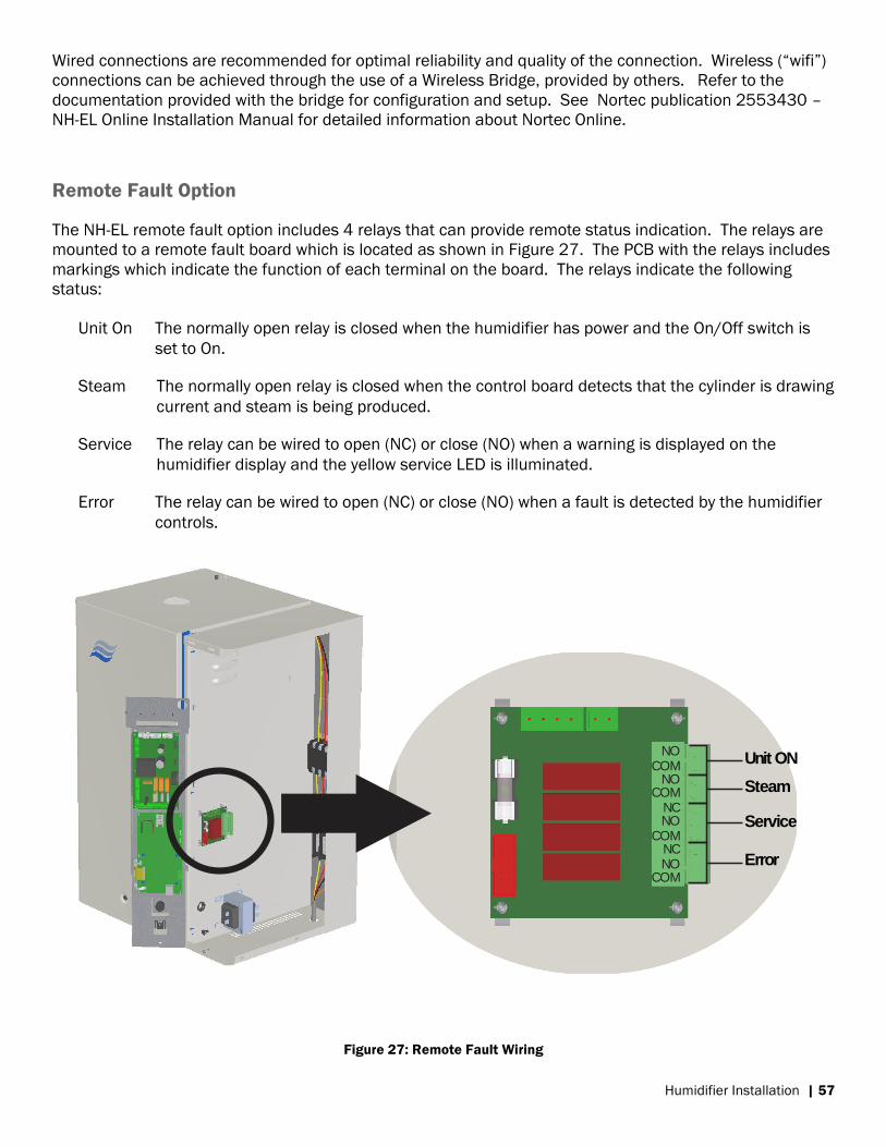
Humidifier Installation | 57
Wired connections are recommended for optimal reliability and quality of the connection. Wireless (“wifi”)
connections can be achieved through the use of a Wireless Bridge, provided by others. Refer to the
documentation provided with the bridge for configuration and setup. See Nortec publication 2553430 –
NH-EL Online Installation Manual for detailed information about Nortec Online.
Remote Fault Option
The NH-EL remote fault option includes 4 relays that can provide remote status indication. The relays are
mounted to a remote fault board which is located as shown in Figure 27. The PCB with the relays includes
markings which indicate the function of each terminal on the board. The relays indicate the following
status:
Unit On The normally open relay is closed when the humidifier has power and the On/Off switch is
set to On.
Steam The normally open relay is closed when the control board detects that the cylinder is drawing
current and steam is being produced.
Service The relay can be wired to open (NC) or close (NO) when a warning is displayed on the
humidifier display and the yellow service LED is illuminated.
Error The relay can be wired to open (NC) or close (NO) when a fault is detected by the humidifier
controls.
Figure 27: Remote Fault Wiring
Steam
Unit ON
Error
Service
NOCOM
NOCOM
NCNO
COMNCNO
COM

58 | Warranty
Warranty
Nortec Humidity Inc. and/or Nortec Humidity Ltd. (hereinafter collectively referred to as THE
COMPANY), warrant for a period of two years after installation or 30 months from
manufacturer’s ship date, whichever date is earlier, that THE COMPANY’s manufactured and
assembled products, not otherwise expressly warranted (with the exception of the cylinder), are
free from defects in material and workmanship. No warranty is made against corrosion,
deterioration, or suitability of substituted materials used as a result of compliance with
government regulations.
THE COMPANY’s obligations and liabilities under this warranty are limited to furnishing
replacement parts to the customer, F.O.B. THE COMPANY’s factory, providing the defective
part(s) is returned freight prepaid by the customer. Parts used for repairs are warranted for the
balance of the term of the warranty on the original humidifier or 90 days, whichever is longer.
The warranties set forth herein are in lieu of all other warranties expressed or implied by law. No
liability whatsoever shall be attached to THE COMPANY until said products have been paid for in
full and then said liability shall be limited to the original purchase price for the product. Any
further warranty must be in writing, signed by an officer of THE COMPANY.
THE COMPANY’s limited warranty on accessories, not of the companies manufacture, such as
controls, humidistats, pumps, etc. is limited to the warranty of the original equipment
manufacturer from date of original shipment of humidifier.
THE COMPANY makes no warranty and assumes no liability unless the equipment is installed in
strict accordance with a copy of the catalog and installation manual in effect at the date of
purchase and by a contractor approved by THE COMPANY to install such equipment.
THE COMPANY makes no warranty and assumes no liability whatsoever for consequential
damage or damage resulting directly from misapplication, incorrect sizing or lack of proper
maintenance of the equipment.
THE COMPANY makes no warranty and assumes no liability whatsoever for damage resulting
from freezing of the humidifier, supply lines, drain lines, or steam distribution systems.
THE COMPANY retains the right to change the design, specification and performance criteria of its
products without notice or obligation

U.S.A 826 Proctor Avenue
Ogdensburg, NY 13669 CANADA
2740 Fenton Road Ottawa, Ontario K1T 3T7
TEL: 1.866.NORTEC1 FAX: 613.822.7964
EMAIL: [email protected] WEBSITE: www.humidity.com