Nessun titolo diapositiva - sarmap – your information ... · to SAR clutter, it is now well...
58
SARscape ® www.sarmap.ch February 2012
Transcript of Nessun titolo diapositiva - sarmap – your information ... · to SAR clutter, it is now well...

SARscape®
www.sarmap.ch February 2012

SARscape®
www.sarmap.ch February 2012
About Synthetic Aperture Radar
SAR systems mainly acquire data in different ways, such as i) single or dual channel mode (for instance
HH or HH/HV or VV/VH), ii) interferometric (single- or repeat-pass) mode, iii) polarimetric mode
(HH,HV,VH,VV), and finally, iv) by combining interferometric and polarimetric acquisition modes.
Obviously, different acquisition modes are subject to different processing techniques. They are:
• Processing of SAR Intensity
The product generation is limited to the intensity processing.
• Interferometric SAR (InSAR/DInSAR) Processing
The product generation includes intensity, and interferometric phase processing.
• Polarimetric SAR (PolSAR) Processing
The product generation includes intensity, and polarimetric phase processing.
• Polarimetric-Interferometric SAR (PolInSAR) Processing
The product generation includes intensity, polarimetric, and interferometric phase processing.

SARscape®
www.sarmap.ch February 2012
Supported spaceborne SAR systems
ERS-1/2 ESA C-band
JERS-1 SAR JAXA L-band
RADARSAT-1/2 CSA & MDA C-band
ENVISAT ASAR ESA C-band
ALOS PALSAR-1 JAXA L-band
TerraSAR-X Germany X-band
SAR Lupe Germany X-band
COSMO-SkyMed ASI X-band
RISAT-1 ISA C-band
Sentinel-1 ESA C-band
ALOS-2 JAXA L-band

SARscape®
www.sarmap.ch February 2012
Supported airborne SAR systems
OrbiSAR-1 up to 0.5 m X, P-band 1-4 pol
TELAER up to 0.5 m X-band 1 pol
E-SAR up to 1 m P,L,C,X-band 1-4 pol
RAMSES up to 0.25 m P,L,S,C,X,Ku,Ka,W-band 1-4 pol
UAV SAR in Stanag format

SARscape®
www.sarmap.ch February 2012
- Modules
• Basic
It includes a set of processing steps for the generation of SAR products based on intensity. This
module is complemented by a multi-purpose tool and by:
• Focusing
It supports the focusing of ERS-1/2 SAR, JERS-1 SAR, ENVISAT ASAR (including Wide Swath
developed by Aresys) and ALOS PALSAR-1 data.
• Gamma & Gaussian Filter
It includes a whole family of SAR specific filters. They are particularly efficient to reduce
speckle, while preserving the radar reflectivity, the textural properties and the spatial
resolution, especially in strongly textured SAR images. Developed in collaboration with
Privateers.

SARscape®
www.sarmap.ch February 2012
• Interferometry
It supports the processing of Interferometric SAR (2-pass interferometry, InSAR) and Differential
Interferometric SAR (n-pass interfereometry, DInSAR) data for the generation of Digital Elevation
Model, Coherence, and Land Displacement/ Deformation maps.
This module is complemented by:
• ScanSAR Interferometry
It offers the capabilities to process InSAR and DInSAR data over large areas (400 by 400 km).
Developed in collaboration with Aresys.
• Interferometric Stacking
Based on Small Baseline Subset (SBAS) and Persistent Scatterers (PS) techniques this module
enables to determine displacements of individual features.
• SAR Polarimetry / Polarimetric Interferometry
It supports the processing of polarimetric and polarimetric interferometric SAR data.
- Modules

SARscape®
www.sarmap.ch February 2012
- Modules
• Quality Assessment Tool
In order to quantitatively assess the geometric, radiometric, and polarimetric quality of SAR
products, a Quality Assessment Tool (QAT) based on a solid methodology is proposed. The overall
architecture of the QAT system supports the quality assessment for ENVISAT ASAR (IM,AP,WS) and
RADARSAT-1 and -2 (FB,SB,WB,EB,ScanSAR) data.
SARscape®
www.sarmap.ch February 2012
- Modules
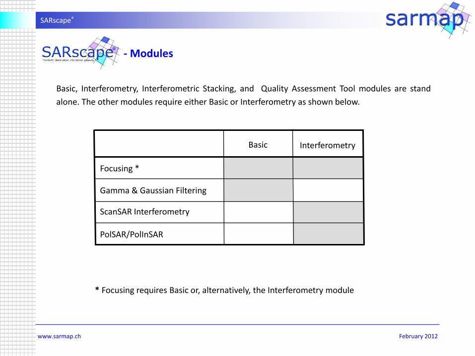
* Focusing requires Basic or, alternatively, the Interferometry module
Basic, Interferometry, Interferometric Stacking, and Quality Assessment Tool modules are stand
alone. The other modules require either Basic or Interferometry as shown below.
PolSAR/PolInSAR
ScanSAR Interferometry
Gamma & Gaussian Filtering
Focusing *
Basic Interferometry

SARscape®
www.sarmap.ch February 2012
Basic Module
Following processing capabilities are supported:
• Multilooking
Generation of multi-looking image from Single Look Complex data.
• Co-registration
In cases where multiple image data sets cover the same region, it is necessary that pixels in different
images correspond so that pixel-by-pixel comparisons can be carried out. Spatial registration may be
necessary, and also resampling, in cases where pixel sizes vary. Coregistration is carried out automatically.
The Basic module includes a set of processing steps for the generation of spaceborne and airborne SAR
products based on intensity and coherence. This is complemented by a multi-purpose tool, which includes a
wide range of functions - from image visualisation, to Digital Elevation Model import and interpolation, to
cartographic and geodetic transforms.

SARscape®
www.sarmap.ch February 2012
• Filtering
It supports a number of conventional single-image filters based on the classical minimum mean square
error and on the anisotropic non-linear diffusion theory. These set of filters is complemented by two
advanced multi-temporal multi-sensor despeckling filters.
• Feature Extraction
Different feature parameters, which are generally used as inputs for classification or quantitative analysis,
can be extracted from intensity and coherence. These are based on first order and time-series statistics.
• Geocoding, Radiometric Calibration and Normalisation
Ellipsoidal or terrain geocoding, using nominal parameters or Ground Control Points, enables the
transformation from radar co-ordinates (either ground or slant range) into a given cartographic reference
system using a rigorous range-Doppler approach. The radiometric calibration, which is performed during
the geocoding, is based on the exploitation of the radar equation. In addition, the radiometric
normalisation enables to empirically correct the effects of the incidence angle on sigma nought by
applying a modified cosine correction.
Basic Module

SARscape®
www.sarmap.ch February 2012
• Mosaicing
It often occurs that the area of interest is covered by several images. In this case SAR images (amplitude
and/or coherence) or products (classification results) can be combined in order to obtain an entire
coverage of the area. When mapping large areas using SAR data, individual image frames have to be
seamlessly joined together to create a consistent mosaic across the region. This method refines the
radiometric variations by comparing the images to be mosaiced in the overlapping areas.
Basic Module

SARscape®
www.sarmap.ch February 2012
• Tools
- Reading and automatic mosaicing of SRTM, RAMP, GTOPO30, ACE DEM data
- Multi-source Digital Elevation Model combination
- Shape, image and DEM cartographic and geodetic transformation
- Slope image generation
- Point target analysis (SAR data)
- Image statistics calculation
- Multi-image operations
- Image resampling
- Images and DEMs interpolation
- Sample selection
- Raster to shape data conversion
- Raster data slicing
- Complex interferogram to phase and module conversion and backward-transformation
- Cartographic to slant geometry conversion
- File transformations
Basic Module

SARscape®
www.sarmap.ch February 2012
Basic – Fully automated JERS-1 SAR Mosaic
© JERS-1 Data JAXA
Mosaic of 1250 JERS-1 SAR ellipsoidal
geocoded images.The mosaicing procedure
has been completely automatic.

SARscape®
www.sarmap.ch February 2012
Basic – Multi-temporal Mosaic, ENVISAT ASAR Data
This product includes around 180
multi-temporal ENVISAT ASAR
images (3 dates, acquired between
May and August 2007) processed
in a fully automated way.
© ASAR Data ESA Senegal

SARscape®
www.sarmap.ch February 2012
Basic – Multi-temporal Multi-sensor Mosaic, ASAR and PALSAR data
This product includes around 160
multi-temporal ENVISAT ASAR and
ALOS PALSAR-1 images (15 meters)
processed in a fully automated way.
© ASAR Data ESA; PALSAR-1 Data JAXA Malawi
ASAR
PALSAR-1
ASAR

SARscape®
www.sarmap.ch February 2012
© COSMO-SkyMed-1 & -2 StripMap Data ASI
Basic – Precise Terrain Geocoding of COSMO-SkyMed-1/2 Products
Coherence
Mean Intensity
Intensity Difference
Time interval 8 days Intensity date 1
Intensity date 2
Intensity Difference

SARscape®
www.sarmap.ch February 2012
Basic – Multi-temporal Speckle Filtering
Original Multi-temporal De Grandi Multi-temporal Anisotropic non-linear Diffusion
© PALSAR-1 Data JAXA

SARscape®
www.sarmap.ch February 2012
Basic – Terrain Geocoded Airborne SAR Data - Quality and Level of Detail
© OrbiSAR-1 Data Orbisat

SARscape®
www.sarmap.ch February 2012
This module provides Single Look Complex (SLC) frame and strip based products starting from the
following raw data:
• ERS-1/2 SAR
• JERS-1 SAR
• ENVISAT ASAR Image Mode
• ENVISAT ASAR Alternating Polarization
• ENVISAT ASAR Wide Swath (based on an algorithm developed by POLIBA)
• ALOS PALSAR-1 Single Polarization
• ALOS PALSAR-1 Dual Polarization
• ALOS PALSAR-1 Full Polarization
Note that:
• The mosaicing of ERS-1/2 SAR and ENVISAT ASAR raw data is supported;
• SLC data generated with this module are not appropriate to derive absolutely radiometric calibrated
values.
Focusing Module

SARscape®
www.sarmap.ch February 2012
Focusing Module – Strip Data Processing
© ASAR Data ESA Ethiopia
ENVISAT ASAR Image Mode

SARscape®
www.sarmap.ch February 2012
Gamma & Gaussian Filtering Module
This module, which is dedicated to the speckle removal in SAR images, includes a whole family of SAR
specific filters. The algorithms are based on Gamma and Gaussian-distributed scene models. They are
particularly efficient to reduce speckle noise, while preserving the radar reflectivity, the textural properties
and the spatial resolution, especially in strongly textured SAR images.
In presence of scene texture, to preserve the useful spatial resolution, e.g. to restore the spatial
fluctuations of the radar reflectivity (texture), an A Priori first order statistical model is needed. With regard
to SAR clutter, it is now well accepted that the Gamma-distributed scene model is the most appropriate.
The Gamma-distributed scene model, modulated by, either an independent complex-Gaussian speckle
model (for SAR SLC images), or by a Gamma speckle model (for multilook detected SAR images), gives rise
to a K-distributed clutter. Nevertheless, the Gaussian-distributed scene model remains still popular, mainly
for mathematical tractability of the inverse problem in case of multi-channel SAR images (multivariate A
Priori scene distributions).

SARscape®
www.sarmap.ch February 2012
Supported SAR filtering methods:
• Single Channel Detected SAR data
- Gamma-Gamma Maximum A Posteriori (MAP)
- Gamma-Distribution-Entropy MAP (DE MAP)
- Gamma A Posteriori Mean
• Multi Channel Detected SAR data
- Gamma-Gaussian MAP filter for uncorrelated speckle
- Gaussian-Gaussian MAP filter for correlated speckle
- Gaussian-DE MAP filter for correlated speckle
• Complex SAR data
- Single Look Complex: Complex Gaussian-DE MAP
- Separate complex looks or interferometric series: Complex Gaussian-Gamma MAP
• Polarimetric SAR data
- Complex Wishart-Gamma MAP
- Complex Wishart-DE MAP
Gamma & Gaussian Filtering Module

SARscape®
www.sarmap.ch February 2012
Gamma & Gaussian Filtering – ALOS PALSAR-1 FBS
Original
Gamma-Gamma MAP
© PALSAR-1 Data JAXA

SARscape®
www.sarmap.ch February 2012
Gamma & Gaussian Filtering – RADARSAT-2 Polarimetric
Original
Complex Wishart-Gamma MAP
© RADARSAT-2 Data MDA

SARscape®
www.sarmap.ch February 2012
The processing includes the following steps:
• Co-registration using Digital Elevation Model provide the proper parameters in order to align the same
points in the two images.
• Common Doppler bandwidth filtering - If there is a difference in the Doppler Centroids, this step allows
minimisation of the decorrelation.
• Interferogram generation - Spectral shift filtering is performed on the image pair, and the Hermitian
product is calculated.
• DEM flattening - Synthetic fringes are generated from a coarser resolution DEM or ellipsoidal height,
using a backward geocoding approach, and then cross-multiplied by the SAR interferogram. This step
allows removal of most of the low frequency components of the wrapped phase, to ease the following
phase unwrapping.
Interferometry Module
This module supports the processing of Interferometric SAR (2-pass interferometry, InSAR) and Differential
Interferometric SAR (n-pass interferometry, DInSAR) data for the generation of Digital Elevation Model,
Coherence, and Land Displacement maps.

SARscape®
www.sarmap.ch February 2012
• Adaptive filtering - The flattened complex interferogram is filtered to improve the phase SNR, improving
the height accuracy of the final DEM.
• Phase unwrapping - The filtered interferogram is unwrapped by using a region growing approach.
• Phase editing – Unwrapping errors can be corrected in a semi-automatic or completely manual way.
• Geometry optimisation, based on Ground Control Points - The orbits are refined in order to obtain an
accurate conversion of the phase information to height and a proper geo-location. Both manual and
automatic procedures for the identification of the most suitable image pixels to be used as GCPs are
implemented.
Interferometry Module

SARscape®
www.sarmap.ch February 2012
• Phase to map conversion – A rigorous approach is implemented, that takes into account the range-
Doppler nature of the SAR acquisition. The final product is obtained in the desired cartographic
reference system, by taking into account all the necessary geodetic and cartographic parameters and
transformations.
• Phase to displacement – The phase values are converted to displacement and geocoded onto a map
projection. The user can enter a specific direction (azimuth angle) and inclination angle along which he
assumes that the main deformation occurred, or even enter an a-priori known deformation field as
input. For the generation of displacement maps it is mandatory to run a second iteration of the
processing, from the interferogram flattening to the phase unwrapping, after the execution of the
baseline fit step (which is aimed at correcting orbital inaccuracies).
Interferometry Module

SARscape®
www.sarmap.ch February 2012
Interferometry – Digital Elevation Model, ERS-Tandem
Switzerland© ERS Data ESA

SARscape®
www.sarmap.ch February 2012
Bolivia
Interferometry – Digital Elevation Model, TerraSAR-X-1
© TSX-1 Data Infoterra

SARscape®
www.sarmap.ch February 2012
Interferometry – Digital Surface and Terrain Mode, OrbiSAR-1 data
Digital Surface Model
X-band
Digital Terrain Model
P-band
Brazil© OrbiSAR-1 Data Orbisat

SARscape®
www.sarmap.ch February 2012
Differential Interferometry, ENVISAT ASAR Image
Bam, Iran
Differential interferogram generated from an ASAR pair
acquired on 3 December 2003 (pre-earthquake) and 11
February 2004 (post-earthquake).
Deformation map obtained considering a strike slip fault
(horizontal movement) with a N-S oriented fault plane. Red
and green tones represent the areas of largest deformation,
while yellowish areas correspond to smaller deformation
zones.
© ASAR Data ESA

SARscape®
www.sarmap.ch February 2012
Differential Interferometry and Atmospheric Effects
ASAR WS
interferometric
phase including
atmospheric
artifacts
ASAR WS
interferometric phase
after reduction
of atmospheric
artifacts and orbital
refinement
MERIS water vapour
for master image
ASAR WS
interferometric
phase after
reduction of
atmospheric
artifacts
© ASAR and MERIS Data ESA

SARscape®
www.sarmap.ch February 2012
ASAR intensity of sea ice ERS-2 - ASAR 28’ phase
Differential Interferometry - Fast Moving Glaciers
Greenland© ASAR and ERS Data ESA

SARscape®
www.sarmap.ch February 2012
Differential Interferometry, TerraSAR-X-1
1 colour cycle ~= 1.55 cm of displacement1 pixel = 3 meter
11 days
44 days
22 days 33 days
55 days 66 days
© TSX-1 Data Infoterra Barcelona

SARscape®
www.sarmap.ch February 2012
Differential Interferometry, Dual Pair Interferometry – Urban
Barcelona
Top Left - Non-linear Displacement Map(dark grey -2.3 cm; bright grey +2.2 cm)
Top Right - Residual Height Map(dark grey -15 m; bright grey +18 m)
Bottom Right - Reference DEM, SRTM-4
© TSX-1 Data Infoterra

SARscape®
www.sarmap.ch February 2012
Differential Interferometry – Interferogram vs. Modeling
COSMO-SkyMed StripMap
differential phase
Synthetic interferogram based on
Okada (direct) model
© INGV

SARscape®
www.sarmap.ch February 2012
The main processing capabilities are:
• ScanSAR Single Look Complex (SLC) Pair Overlap Estimation
ScanSAR data alignment, and burst overlapping, is estimated using sensor orbit descriptions.
• Doppler Common Band Filtering
Common azimuth bandwidth is selected on the master and slave bursts, minimising the signal
decorrelation.
• Burst Coregistration
Coregistration coefficients are computed using sensor orbit descriptions. The slave burst is then
resampled over the master burst grid.
ScanSAR Interferometry Module
This module extends the Interferometry one to the ScanSAR mode, offering the capabilities to generate
interferograms over large areas (400 x 400 km). This module enables also the generation of Digital
Elevation Model, Coherence and Land Displacement maps based on ENVISAT ASAR Wide Swath data. In
addition this module provides also hybrid interferometric products, by combining StripMode (ASAR Image
Mode) data with ScanSAR (ASAR Wide Swath) ones.

SARscape®
www.sarmap.ch February 2012
• Interferogram Generation
Coregistered bursts are filtered along the range direction in order to minimise the geometrical
decorrelation; either Synthetic fringes or a flat Earth interferogram can be used for this purpose. The
interferogram is subsequently generated as an Hermitian product between masterand coregistered
slave bursts.
• Single Swath Interferogram and Single Swath Detected Image Generation
Single burst interferograms are collected and coherently summed providing a multilooked interferogram
image for each ScanSAR swath. In the same step the single bursts absolute value data are collected,
weighted with a de-scalloping window, and incoherently summed, providing two (master and slave)
single swath, coregistered detected images.
• Swaths Recomposing
Single swath data (interferogram and detected data) are composed into multi swath images.
ScanSAR Interferometry Module

SARscape®
www.sarmap.ch February 2012
ScanSAR Interferometry – ENVISAT ASAR Wide Swath
May - June 2005
CoherenceMean Intensity Intensity Change
Senegal © ASAR Data ESA

SARscape®
www.sarmap.ch February 2012
Bam, Iran
ScanSAR Differential Interferometry – ENVISAT ASAR Wide Swath
400 km
100 km
Image Mode
© ASAR Data ESA
SARscape®
www.sarmap.ch February 2012
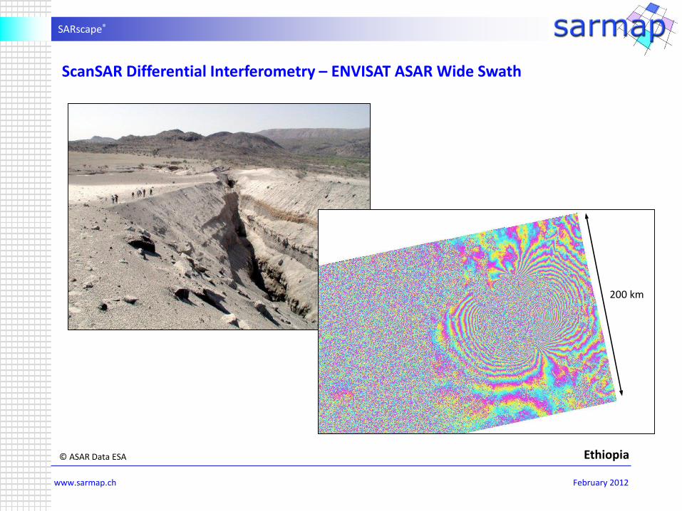
Ethiopia
200 km
ScanSAR Differential Interferometry – ENVISAT ASAR Wide Swath
© ASAR Data ESA

SARscape®
www.sarmap.ch February 2012
Interferometric Stacking Module
The Interferometric Stacking module integrates point-based (PS-like) and area-based (SBAS-like) techniques
for the processing of interferometric stacks. This combined approach allows analyzing deformation
phenomena affecting both extended area (e. g. natural features) and localized structures (e. g. man made
features), related to natural or man-induced phenomena (e. g. volcanic or seismic activity, landslides,
subsidence, building failures, etc.).
• Small Baseline Subset (SBAS)
Is a complementary method that exploits differential SAR interferometry techniques to analyse stacks of
SAR acquisitions to extract small deformations over large areas, where no point targets might be
identified but large, correlated displacements occur over natural targets.
• Persistent Scatterers (PS)
Enables to detect very small displacements (mm scale) and to infer the deformation velocity - and its
variation over the time - in particular for very stable (man-made) reflectors that might have independent
displacements respect to the surrounding areas.

SARscape®
www.sarmap.ch February 2012
PS - Point-based SBAS - Area-based
Independent, incorrelated motions At best spatially correlated motions
Pixelwise continuous time seriesPossibility of handling time seriers with
temporal holes
Time interval between two acquisitions limited by displacement rate
Time interval between two acquisitions limited by temporal decorrelation
Very accurate on PS Slightly less accurate
Linear displacements favouredParametric models possible
Non-parametric modeling possible
Interferometric Stacking Module

SARscape®
www.sarmap.ch February 2012
SBAS based on 30 ENVISAT ASAR Image Mode data
© ASAR Data ESA Middle East

SARscape®
www.sarmap.ch February 2012
SBAS based on ALOS PALSAR-1 data
Average displacement rate (color scale between -15 and +5 mm/year) of an area around the cities of Tokyo and Chiba, Japan,derived from ALOS PALSAR-1 data in the period 2006-2010. Whole area (left), a region of terrain compaction over landfill(center), uplift due to too much water injection after natural gas extraction (right).
Location time series of groups of terrain points in a same area showing different temporal behaviors, as obtained fromInterferometric Stacking techniques . Points showing linear trends (left), and points with significant non-linearities (right);vertical scale in [mm].

SARscape®
www.sarmap.ch February 2012
PS based on 25 ENVISAT ASAR Image Mode data
© ASAR Data ESA Beijing

SARscape®
www.sarmap.ch February 2012
Polarimetry and Polarimetric Interferometry Module
The processing capabilities of SAR Polarimetry are:
• Polarimetric Calibration Matrix
Polarimetric calibration allows to minimize the impact of non ideal behaviours of a full polarimetric SAR
acquisition system, to obtain an estimate of the scattering matrix of the imaged objects as accurate as
possible from their available measurement. Polarimetric calibration is performed based on defined
calibration matrixes.
• Polarimetric Signature
This function provides an estimate of the polarimetric signature of a point-target-like object, whose
location is specified either in terms of its range and azimuth indexes within a slant-range acquisition, or
through its known cartographic coordinates.
• Polarimetric Synthesis
The availability of a full polarimetric acquisition, for example based on a linearly polarized base, allows
to synthesize any desired elliptical polarization. Starting from a set of full polarimetric linearly polarized
Single Look Complex (SLC) data, this module allows to synthesize a new set of SLC data in a desired
orthogonal basis, either circular, linear rotated of 45 degrees or generic elliptical of user defined
orientation and ellipticity.

SARscape®
www.sarmap.ch February 2012
Polarimetry and Polarimetric Interferometry Module
• Polarimetric Features
This function performs the computation of conventional polarimetric features - among others the Linear
Depolarization Ratio, the Polarimetric Phase Difference, and the Polarization HH-VV Ratio - based on the
scattering matrix.
• Pauli Decomposition
The Pauli coherent decomposition provides an interpretation of a full polarimetric SLC data set in terms
of elementary scattering mechanisms: sphere/plate/trihedral (single- or odd-bounce scattering),
dihedral oriented at 0o (double- or even-bounce) and diplane oriented at 45o (qualitatively related also
to volume scattering).
• Entropy-Anisotropy-Alfa Decomposition
The Entropy-Anisotropy-Alpha decomposition performs an eigen-decomposition of the coherency
matrix of a full polarimetric SLC data set. The output aree:
- Entropy - it is related to degree of randomness of the scattering process
- Anisotropy - it measures the relative importance of 2nd and 3rd eigenvalue
- Alpha - it relates the type of scattering mechanism

SARscape®
www.sarmap.ch February 2012
Polarimetry and Polarimetric Interferometry Module
• Entropy-Anisotropy-Alfa Classification
It performs an unsupervised classification of the results of a previous Entropy-Anisotropy-Alpha
decomposition step, identifying the main scattering type of every pixel in the target area.
Entropy-Anisotropy-Alfa Decomposition based on ALOS PALSAR-1 PLR data
© PALSAR-1 Data JAXA

SARscape®
www.sarmap.ch February 2012
Polarimetry and Polarimetric Interferometry Module
The processing capabilities of Polarimetric SAR Interferometry are:
• Single Look Complex Coregistration
This function performs an unsupervised classification of the results of a previous Entropy-Anisotropy-
Alpha decomposition step, identifying the main scattering type of every pixel in the target area.
• Polarimetric Phase Difference / Interferogram Generation
This function performes i) the Polarimetric Phase Difference using the HH and VV polarization of the
same acquisition, and ii) it generates interferograms using the same polarization of the PolInSAR pair.
• Polarimetric / Interferometric Coherence
This function generates correlation/coherence images based on Polarimetric Phase Difference /
Interferogram products.
• Coherence Optimization
This function estimates the main scattering mechanisms of a full polarimetric pair of linear acquisitions,
identifying those mechanisms that correspond to the highest value of interferometric coherence. The
corresponding interferograms and coherence maps are provided as result.

SARscape®
www.sarmap.ch February 2012
Quality Assessment Tool
In order to quantitatively assess the geometric, radiometric, and polarimetric quality of SAR products, a
Quality Assessment Tool (QAT) based on a solid methodology is proposed. The overall architecture of the
QAT system supports the quality assessment for ENVISAT ASAR (IM,AP,WS) and RADARSAT-1 and -2
(FB,SB,WB,EB,ScanSAR) data.

SARscape®
www.sarmap.ch February 2012
Following quality parameters and assessment procedures are supported:
- Background removal and image interpolation
- Impulse Response Function measurements
- Spatial resolution in range and azimuth
- Peak Side Lobe ratio
- Range and azimuth Peak Side Lobe ratio
- Spurious sidelobe ratio
- Integrated Side Lobe Ratio
- Derivation of sigma nought and radiometric calibration
- Sigma nought derivation for ASAR ground range projected products
- Sigma nought derivation for ASAR single complex slant range projected products
- Beta nought for derivation or RADARSAT-1 detected products
- Beta nought derivation for RADARSAT-1 single look complex products
- Conversion from beta nought to sigma nought
- Calibration constant determination
- Radiometric analysis
- Radiometric accuracy
- Radiometric resolution
- Equivalent Number of Looks
- Radiometric stability
- Noise equivalent sigma nought
Quality Assessment Tool

SARscape®
www.sarmap.ch February 2012
- Ambiguity analysis
- Azimuth ambiguity location offset
- Range ambiguity location offset
- Point target ambiguity ratio
- Geometric analysis
- Level 1 products geocoding
- Absolute location accuracy
- Sampling Window Start Time bias
- Ground Control Point geocoding and residual analysis
- Swath width and position
- Channel co-registration
- Multi-temporal co-registration
- Ratio
- Polarimetric analysis
- Polarimetric Phase Difference and polarimetric coherence
- Polarimetric signature
Quality Assessment Tool

SARscape®
www.sarmap.ch February 2012
The Quality Assessment Tool is composed by three logical parts:
• All what concerns Graphical User Interface (GUI), data, and information display is integrated within the ENVI® environment
(Window® and Linux®). This solution allows to obtain professional tools for data visualisation both for raster and vector
data in standard formats, and it enables to exploit the existing basic analysis tools already available within ENVI®. This
layer has the purpose of driving the execution of the different Quality Assessment funcions in an interactive way as well as
displaying their results, in terms of images, textual data and plots.
• All modules related to initial data import and assessment are available as executable modules, originally written in C++
and that may be invoked both through the mentioned GUI and as command-line modules. Data import, in particular, has
the purpose of interfacing the QAT system with SAR data originating from different platforms, and hence stored and
delivered in different formats. The data stored in these formats are analysed during import phase, all the necessary
parameters are extracted and stored in a XML file with common syntax (documented in the delivered documentation).
The binary data (image products) are stored in a plain matrix (BIL) file, and a correspondent .hdr file is generated,
consistent with ENVI® specifications, to allow the direct display of the binary data within the ENVI® environment. All
Quality Assessment functions deal directly with the data imported into a common meta-format.
• The third layer of database has the purpose of intercepting all the results of the Quality Assessment functions and storing
them within a history database, as well as storing reference and nominal values for important parameters. A part of the
database is dedicated to storing information concerning Ground Control Points to be reused during a long-time
assessment of SAR data quality over a same reference test-site.
Quality Assessment Tool

SARscape®
www.sarmap.ch February 2012
• Airborne SAR
» Proper handling of motion compensated data
» Height dependent coregistration
» Proper handling of azimuth-varying Doppler spectrum
• Spotlight
TerraSAR-X, COSMO-Skymed, SAR-Lupe
» Height dependent coregistration
» Proper handling of azimuth-varying Doppler spectrum
• ScanSAR interferometry
ASAR WS
» Proper handling of azimuth-varying Doppler spectrum
• Cross-mode
PALSAR FBS – FBD – PLR, ASAR WS – IM, ERS-2 – ASAR
» Processing optimised for all different cases
- Key Features

SARscape®
www.sarmap.ch February 2012
- Key Features
• Phase-preserving SAR focussing: high precision SLC data can be obtained from SAR raw data, starting
from either Image mode or ScanSAR products, using an w-k algorithm.
• Automatic coregistration of multi-temporal SAR or optical image stacks: using cross-corrrelation
techniques, pixel-accuracy is obtained without need of manual selection of corresponding points.
• Multi-temporal speckle filter: when several SAR acquisitions are available over a same area, this
additional unique filtering functionality allows to obtain high speckle reduction while conserving all
spatial and temporal information.
• A dedicate SAR filtering module, based on the most advanced Gamma and Gaussian distributed scene
models, is suitable for products such as SLC, PRI, Multitemporal data sets, etc.
• One-step coherence maps computation: all processing steps necessary to generate such products can be
performed as just one operation.
• Rigorous geocoding of SAR data based on Range-Doppler equations. Accurate terrain correction can be
performed when a DEM is available; radiometric correction is performed by rigorously considering the
radar equation.

SARscape®
www.sarmap.ch February 2012
• Identification of Ground Control Points in the SAR image is supported by an archive.
• Radiometric and geometric calibration of optical data can be performed during geocoding, based on
DEM information when available.
• A wide number of cartographic reference systems is available for the geocoded products; the user can
extend it by providing all necessary parameters in easily accessible ASCII files.
• Batch processing: long sequences of processing steps can be collected in one batch command and run as
a single operation. Script programming is available as well.
• The interferometric processing chain can be applied to both medium resolution (e.g. ASAR Wide Swath
products) and high resolution (e.g. ASAR Image mode products) data.
• Tailored and dedicated data mosaicing routines are developed to join at the best amplitude as well as
DEM images.
• High accuracy DEMs can be generated using the interferometric module.
• Differential interferograms can be generated using the interferometric module to estimate small terrain
movements (in the order of few millimetres).
- Key Features

SARscape®
www.sarmap.ch February 2012
• External DEMs can be imported; USGS GTOPO-30 and SRTM-3 world-wide DEMs can be automatically
extracted and mosaiced over the area of interest by simply inputting the reference slant range or
geocoded image.
• Both Windows and Linux operating systems are supported.
• Integration in well-known GIS or image processing environments, allowing the user to exploit a wide
base of tools together with the specific capabilities of SARscape®. The user can select the preferred
environment suiting at best with his applications, accessing the same processing routines and even
sharing the same data between the two platforms.
• Standard open formats are used for all generated products.
- Key Features